US8179604B1 - Wearable marker for passive interaction - Google Patents
Wearable marker for passive interactionDownload PDFInfo
- Publication number
- US8179604B1 US8179604B1US13/249,555US201113249555AUS8179604B1US 8179604 B1US8179604 B1US 8179604B1US 201113249555 AUS201113249555 AUS 201113249555AUS 8179604 B1US8179604 B1US 8179604B1
- Authority
- US
- United States
- Prior art keywords
- wearable
- hmd
- item
- pattern
- hand
- Prior art date
- Legal status (The legal status is an assumption and is not a legal conclusion. Google has not performed a legal analysis and makes no representation as to the accuracy of the status listed.)
- Expired - Fee Related
Links
Images


Classifications
- G—PHYSICS
- G02—OPTICS
- G02B—OPTICAL ELEMENTS, SYSTEMS OR APPARATUS
- G02B27/00—Optical systems or apparatus not provided for by any of the groups G02B1/00 - G02B26/00, G02B30/00
- G02B27/0093—Optical systems or apparatus not provided for by any of the groups G02B1/00 - G02B26/00, G02B30/00 with means for monitoring data relating to the user, e.g. head-tracking, eye-tracking
- G—PHYSICS
- G02—OPTICS
- G02B—OPTICAL ELEMENTS, SYSTEMS OR APPARATUS
- G02B27/00—Optical systems or apparatus not provided for by any of the groups G02B1/00 - G02B26/00, G02B30/00
- G02B27/01—Head-up displays
- G02B27/017—Head mounted
- G02B27/0172—Head mounted characterised by optical features
- G—PHYSICS
- G06—COMPUTING OR CALCULATING; COUNTING
- G06F—ELECTRIC DIGITAL DATA PROCESSING
- G06F1/00—Details not covered by groups G06F3/00 - G06F13/00 and G06F21/00
- G06F1/16—Constructional details or arrangements
- G06F1/1613—Constructional details or arrangements for portable computers
- G06F1/163—Wearable computers, e.g. on a belt
- G—PHYSICS
- G06—COMPUTING OR CALCULATING; COUNTING
- G06F—ELECTRIC DIGITAL DATA PROCESSING
- G06F3/00—Input arrangements for transferring data to be processed into a form capable of being handled by the computer; Output arrangements for transferring data from processing unit to output unit, e.g. interface arrangements
- G06F3/01—Input arrangements or combined input and output arrangements for interaction between user and computer
- G06F3/017—Gesture based interaction, e.g. based on a set of recognized hand gestures
- G—PHYSICS
- G06—COMPUTING OR CALCULATING; COUNTING
- G06F—ELECTRIC DIGITAL DATA PROCESSING
- G06F3/00—Input arrangements for transferring data to be processed into a form capable of being handled by the computer; Output arrangements for transferring data from processing unit to output unit, e.g. interface arrangements
- G06F3/01—Input arrangements or combined input and output arrangements for interaction between user and computer
- G06F3/03—Arrangements for converting the position or the displacement of a member into a coded form
- G06F3/0304—Detection arrangements using opto-electronic means
- G—PHYSICS
- G03—PHOTOGRAPHY; CINEMATOGRAPHY; ANALOGOUS TECHNIQUES USING WAVES OTHER THAN OPTICAL WAVES; ELECTROGRAPHY; HOLOGRAPHY
- G03H—HOLOGRAPHIC PROCESSES OR APPARATUS
- G03H1/00—Holographic processes or apparatus using light, infrared or ultraviolet waves for obtaining holograms or for obtaining an image from them; Details peculiar thereto
- G03H1/22—Processes or apparatus for obtaining an optical image from holograms
- G03H1/2294—Addressing the hologram to an active spatial light modulator
- G—PHYSICS
- G03—PHOTOGRAPHY; CINEMATOGRAPHY; ANALOGOUS TECHNIQUES USING WAVES OTHER THAN OPTICAL WAVES; ELECTROGRAPHY; HOLOGRAPHY
- G03H—HOLOGRAPHIC PROCESSES OR APPARATUS
- G03H1/00—Holographic processes or apparatus using light, infrared or ultraviolet waves for obtaining holograms or for obtaining an image from them; Details peculiar thereto
- G03H1/0005—Adaptation of holography to specific applications
- G03H2001/0061—Adaptation of holography to specific applications in haptic applications when the observer interacts with the holobject
- G—PHYSICS
- G03—PHOTOGRAPHY; CINEMATOGRAPHY; ANALOGOUS TECHNIQUES USING WAVES OTHER THAN OPTICAL WAVES; ELECTROGRAPHY; HOLOGRAPHY
- G03H—HOLOGRAPHIC PROCESSES OR APPARATUS
- G03H2225/00—Active addressable light modulator
- G03H2225/60—Multiple SLMs
- G—PHYSICS
- G06—COMPUTING OR CALCULATING; COUNTING
- G06F—ELECTRIC DIGITAL DATA PROCESSING
- G06F2203/00—Indexing scheme relating to G06F3/00 - G06F3/048
- G06F2203/033—Indexing scheme relating to G06F3/033
- G06F2203/0331—Finger worn pointing device
Definitions
- Various technologiescan be utilized to provide users with electronic access to data and services in communication networks, as well as to support communication between users.
- devicessuch as computers, telephones, and personal digital assistants (PDAs) can be used to exchange information over communication networks including the Internet.
- Communication networksmay in turn provide communication paths and links to servers, which can host applications, content, and services that may be accessed or utilized by users via communication devices.
- the contentcan include text, video data, audio data and/or other types of data.
- an example embodiment presented hereinprovides a computer-implemented method comprising: at a wearable head-mount display (HMD), detecting infrared (IR) radiation reflected from an IR reflective surface on a hand-wearable item, the IR reflective surface being in the form of a particular surface pattern and being substantially optically invisible; decoding the particular surface pattern from the detected IR radiation to obtain an item identifier; determining that the item identifier matches a predetermined identifier associated with the wearable HMD; and responsive to determining that the item identifier matches the predetermined identifier, tracking position and motion of the hand-wearable item relative to the wearable HMD by measuring position and motion of the particular surface pattern relative to the wearable HMD via the detected IR radiation.
- HMDwearable head-mount display
- IRinfrared
- an example embodiment presented hereinprovides a wearable head-mounted display (HMD) comprising: means for detecting infrared (IR) radiation reflected from an IR reflective surface on a hand-wearable item, wherein the IR reflective surface is in the form of a particular surface pattern and is substantially optically invisible; means for decoding the particular surface pattern from the detected IR radiation to obtain an item identifier; means for determining that the item identifier matches a predetermined identifier associated with the wearable HMD; and means for responding to determining that the item identifier matches the predetermined identifier by measuring position and motion of the particular surface pattern relative to the wearable HMD via the detected IR radiation, in order to track position and motion of the hand-wearable item relative to the wearable HMD.
- IRinfrared
- an example embodiment presented hereinprovides a nontransitory computer-readable medium having instructions stored thereon that, upon execution by one or more processors of a wearable head-mounted display HMD, cause the wearable HMD to carry out functions comprising: detecting infrared (IR) radiation reflected from an IR reflective surface on a hand-wearable item, wherein the IR reflective surface is in the form of a particular surface pattern and is substantially optically invisible; decoding the particular surface pattern from the detected IR radiation to obtain an item identifier; determining that the item identifier matches a predetermined identifier associated with the wearable HMD; and responsive to determining that the item identifier matches the predetermined identifier, tracking position and motion of the hand-wearable item relative to the wearable HMD by measuring position and motion of the particular surface pattern relative to the wearable HMD via the detected IR radiation.
- IRinfrared
- FIG. 1 ais a first view of an example wearable head-mounted display for receiving, transmitting and displaying data, in accordance with an example embodiment.
- FIG. 1 bis a second view of an example wearable head-mounted display of FIG. 1 a , in accordance with an example embodiment.
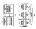
- FIG. 2is block diagram of a wearable head-mounted display, in accordance with an example embodiment.
- FIG. 3is a simplified block diagram of a communication network, in accordance with an example embodiment.
- FIG. 4 ais a block diagram of a computing device, in accordance with an example embodiment.
- FIG. 4 bdepicts a network with clusters of computing devices of the type shown in FIG. 4 a , in accordance with an example embodiment.
- FIG. 5illustrates a wearable marker for passive interaction with a wearable computing device, according to an example embodiment.
- FIG. 6illustrates triangulation of a wearable marker by a wearable computing device, according to an example embodiment.
- FIG. 7illustrates tracking of a wearable marker by a wearable computing device, according to an example embodiment.
- FIG. 8is illustrates example wearable markers, according to an example embodiment.
- FIG. 9is a flowchart illustrating an example embodiment of a method in a wearable computing device for passively interacting with a wearable marker.
- a wearable markermay be used for passive interaction with a wearable computing device.
- a wearable markermay take the form of a ring, a bracelet, an artificial fingernail configured to be affixed to a fingernail, a decal configured to be affixed to a fingernail, or a glove, among other possible wearable items.
- a wearable markermay further include an infrared (IR) reflective surface in the form of a surface pattern, the IR reflective surface being substantially optically invisible.
- the surface patterncould include a number, a pattern of lines, a pattern of shapes, an image, or other pictorial design rendering, for example. Being part of the IR reflective surface, the surface pattern may also be substantially optically invisible.
- Both the IR reflective surface and the included surface patternmay be configured to be visible to (or detectable by) an IR detection device, such as an IR camera or other IR detector via reflected IR radiation.
- a wearable computing devicemay include a head-mounted display (HMD) having eyeglasses or goggles that can combine computer-generated images displayed on the eye-facing surfaces of lens elements with an actual field of view observable through the lens elements.
- HMDhead-mounted display
- the capability presenting the combination of the actual, observed field-of-view (FOV) with the displayed, computer-generated imagescan be complemented or supplemented with various functions and applications, as well as with various forms of user input and sensory data from ancillary wearable computing components, to provide rich and varied experiences and utility for a user or wearer of the HMD.
- a HMDcan be further equipped with an IR camera device capable of detecting IR radiation, and in particular, capable of detecting and recognizing the IR reflective surface pattern on a hand-wearable item (such as a ring) via reflected IR radiation.
- the HMD and the IR camera devicecan function together to track position and motion of the hand-wearable item within a FOV of the HMD, and by doing so can recognize known patterns of motion that correspond to known hand gestures. Recognition of a known pattern of motion can accordingly be used to identify a known hand gesture, which in turn can form a basis for user input to the HMD. For example, a particular gesture could be associated with a particular command, application, or other invokable action on the HMD.
- an HMDcan be communicatively connected with a communication network, and can exchange data with a server or server system (other device) in the network.
- applications and/or commands invoked by hand gesturescould involve communication with a server or server system in the communication network.
- a hand gesturecould cause a program running on the wearable HMD to upload and/or download content (e.g., media data) to/from the server.
- the hand-wearable item bearing the IR reflective surface patterncould be configured as multiple items bearing multiple, corresponding pattern components.
- the hand-wearable itemcould include multiple rings, multiple artificial fingernails, or multiple fingernail decals. Multiple pattern components could be used support complex gestures, for example ones involving two or more fingers and associated motion.
- the hand-wearable itemcould take the form of a fashionable or stylish adornment having potential marketing value beyond its function in passive interaction.
- a wearable computing systemmay comprise various components, including one or more processors, one or more forms of memory, one or more sensor devices, one or more I/O devices, one or more communication devices and interfaces, and a head-mounted display (HMD), all collectively arranged in a manner to make the system wearable by a user.
- the wearable computing systemmay also include machine-language logic (e.g., software, firmware, and/or hardware instructions) stored in one or another form of memory and executable by one or another processor of the system in order to implement one or more programs, tasks, applications, or the like.
- machine-language logice.g., software, firmware, and/or hardware instructions
- the wearable computing systemmay be configured in various form factors, including, without limitation, integrated in the HMD as a unified package, or distributed, with one or more elements integrated in the HMD and one or more others separately wearable (e.g., as a garment, in a garment pocket, as jewelry, etc.).
- wearable head-mounted displayor “wearable HMD”
- head-mounted displayor just “head-mounted display” (or “HMD”) will be used herein to refer to a wearable computing system, in either an integrated (unified package) form, a distributed (or partially distributed) form, or other wearable form.
- FIG. 1 aillustrates an example wearable computing system 100 for receiving, transmitting, and displaying data.
- the wearable computing system 100is depicted as a wearable HMD taking the form of eyeglasses 102 .
- eyeglasses 102the wearable computing system 100
- FIG. 1 aillustrates an example wearable computing system 100 for receiving, transmitting, and displaying data.
- the wearable computing system 100is depicted as a wearable HMD taking the form of eyeglasses 102 .
- eyeglasses 102the wearable computing system 100 is depicted as a wearable HMD taking the form of eyeglasses 102 .
- other types of wearable computing devicescould additionally or alternatively be used.
- the eyeglasses 102comprise frame elements including lens-frames 104 and 106 and a center frame support 108 , lens elements 110 and 112 , and extending side-arms 114 and 116 .
- the center frame support 108 and the extending side-arms 114 and 116are configured to secure the eyeglasses 102 to a user's face via a user's nose and ears, respectively.
- Each of the frame elements 104 , 106 , and 108 and the extending side-arms 114 and 116may be formed of a solid structure of plastic or metal, or may be formed of a hollow structure of similar material so as to allow wiring and component interconnects to be internally routed through the eyeglasses 102 .
- Each of the lens elements 110 and 112may include a material on which an image or graphic can be displayed. In addition, at least a portion of each lens elements 110 and 112 may be sufficiently transparent to allow a user to see through the lens element. These two features of the lens elements could be combined; for example, to provide an augmented reality or heads-up display where the projected image or graphic can be superimposed over or provided in conjunction with a real-world view as perceived by the user through the lens elements.
- the extending side-arms 114 and 116are each projections that extend away from the frame elements 104 and 106 , respectively, and are positioned behind a user's ears to secure the eyeglasses 102 to the user.
- the extending side-arms 114 and 116may further secure the eyeglasses 102 to the user by extending around a rear portion of the user's head.
- the wearable computing system 100may be connected to or be integral to a head-mounted helmet structure. Other possibilities exist as well.
- the wearable computing system 100may also include an on-board computing system 118 , a video camera 120 , a sensor 122 , a finger-operable touch pad 124 , and a communication interface 126 .
- the on-board computing system 118is shown to be positioned on the extending side-arm 114 of the eyeglasses 102 ; however, the on-board computing system 118 may be provided on other parts of the eyeglasses 102 .
- the on-board computing system 118may include, for example, a one or more processors and one or more forms of memory.
- the on-board computing system 118may be configured to receive and analyze data from the video camera 120 , the sensor 122 , the finger-operable touch pad 124 , and the wireless communication interface 126 (and possibly from other sensory devices and/or user interfaces) and generate images for output to the lens elements 110 and 112 .
- the video camera 120is shown to be positioned on the extending side-arm 114 of the eyeglasses 102 ; however, the video camera 120 may be provided on other parts of the eyeglasses 102 .
- the video camera 120may be configured to capture images at various resolutions or at different frame rates. Video cameras with a small form factor, such as those used in cell phones or webcams, for example, may be incorporated into an example of the wearable system 100 .
- FIG. 1 aillustrates one video camera 120 , more video cameras may be used, and each may be configured to capture the same view, or to capture different views.
- the video camera 120may be forward facing to capture at least a portion of a real-world view perceived by the user. This forward facing image captured by the video camera 120 may then be used to generate an augmented reality where computer generated images appear to interact with the real-world view perceived by the user.
- the video camera 120may also include IR detection capability, such that it may functionality within an IR region of the electromagnetic spectrum.
- IR detection capabilitysuch that it may functionality within an IR region of the electromagnetic spectrum.
- the operational properties of the video camera 120 described abovecould apply to IR as well as optical light.
- the video camera 120could detect IR radiation reflected from an IR reflective surface pattern on a hand-wearable item (such as ring, or fingernail decal), for example, and track the position and motion of the hand-wearable item in FOV of the video camera 120 via IR radiation reflected from the hand-wearable item.
- an IR camera devicecould be included on the wearable HMD as a separate component or separate device from the video camera 120 . Other configurations are possible as well.
- the sensor 122is shown mounted on the extending side-arm 116 of the eyeglasses 102 ; however, the sensor 122 may be provided on other parts of the eyeglasses 102 . Although depicted as a single component, the sensor 122 in FIG. 1 a could include more than one type of sensor device or element.
- the sensor 122could include one or more of a motion detector (e.g., a gyroscope and/or an accelerometer), a location determination device (e.g., a GPS device), a magnetometer, and an orientation sensor (e.g., a theodolite).
- a motion detectore.g., a gyroscope and/or an accelerometer
- a location determination devicee.g., a GPS device
- magnetometere.g., a magnetometer
- an orientation sensore.g., a theodolite
- the finger-operable touch pad 124shown mounted on the extending side-arm 114 of the eyeglasses 102 , may be used by a user to input commands.
- the finger-operable touch pad 124may sense at least one of a position and a movement of a finger via capacitive sensing, resistance sensing, or a surface acoustic wave process, among other possibilities.
- the finger-operable touch pad 124may be capable of sensing finger movement in a direction parallel to the pad surface, in a direction normal to the pad surface, or both, and may also be capable of sensing a level of pressure applied.
- the finger-operable touch pad 124may be formed of one or more translucent or transparent insulating layers and one or more translucent or transparent conducting layers.
- Edges of the finger-operable touch pad 124may be formed to have a raised, indented, or roughened surface, so as to provide tactile feedback to a user when the user's finger reaches the edge of the finger-operable touch pad 124 .
- the eyeglasses 102could include one more additional finger-operable touch pads, for example attached to the extending side-arm 316 , which could be operated independently of the finger-operable touch pad 124 to provide a duplicate and/or different function.
- the communication interface 126could include an antenna and transceiver device for support of wireline and/or wireless communications between the wearable computing system 100 and a remote device or communication network.
- the communication interface 126could support wireless communications with any or all of 3G and/or 4G cellular radio technologies (e.g., CDMA, EVDO, GSM, UMTS, LTE, WiMAX), as well as wireless local or personal area network technologies such as a Bluetooth, Zigbee, and WiFi (e.g., 802.11a, 802.11b, 802.11g).
- 3G and/or 4G cellular radio technologiese.g., CDMA, EVDO, GSM, UMTS, LTE, WiMAX
- wireless local or personal area network technologiessuch as a Bluetooth, Zigbee, and WiFi (e.g., 802.11a, 802.11b, 802.11g).
- Other types of wireless access technologiescould be supported as well.
- the communication interface 126could enable communications between the wearable computing system 100 and one or more end devices, such as another wireless communication device (e.g., a cellular phone or another wearable computing device), a user at a computer in a communication network, or a server or server system in a communication network.
- the communication interface 126could also support wired access communications with Ethernet or USB connections, for example.
- FIG. 1 billustrates another view of the wearable computing system 100 of FIG. 1 a .
- the lens elements 110 and 112may act as display elements.
- the eyeglasses 102may include a first projector 128 coupled to an inside surface of the extending side-arm 116 and configured to project a display image 132 onto an inside surface of the lens element 112 .
- a second projector 130may be coupled to an inside surface of the extending side-arm 114 and configured to project a display image 134 onto an inside surface of the lens element 110 .
- the lens elements 110 and 112may act as a combiner in a light projection system and may include a coating that reflects the light projected onto them from the projectors 128 and 130 .
- the projectors 128 and 130could be scanning laser devices that interact directly with the user's retinas.
- a forward viewing fieldmay be seen concurrently through lens elements 110 and 112 with projected or displayed images (such as display images 132 and 134 ). This is represented in FIG. 1 b by the field of view (FOV) object 136 -L in the left lens element 112 and the same FOV object 136 -R in the right lens element 110 .
- FOVfield of view
- the combination of displayed images and real objects observed in the FOVmay be one aspect of augmented reality, referenced above.
- lens elements 110 , 112may include: a transparent or semi-transparent matrix display, such as an electroluminescent display or a liquid crystal display; one or more waveguides for delivering an image to the user's eyes; and/or other optical elements capable of delivering an in focus near-to-eye image to the user.
- a corresponding display drivermay be disposed within the frame elements 104 and 106 for driving such a matrix display.
- a scanning laser devicesuch as low-power laser or LED source and accompanying scanning system, can draw a raster display directly onto the retina of one or more of the user's eyes. The user can then perceive the raster display based on the light reaching the retina.
- the wearable system 100can also include one or more components for audio output.
- wearable computing system 100can be equipped with speaker(s), earphone(s), and/or earphone jack(s). Other possibilities exist as well.
- the wearable computing system 100 of the example embodiment illustrated in FIGS. 1 a and 1 bis configured as a unified package, integrated in the HMD component
- the wearable computing system 100could be implemented in a distributed architecture in which all or part of the on-board computing system 118 is configured remotely from the eyeglasses 102 .
- some or all of the on-board computing system 118could be made wearable in or on clothing as an accessory, such as in a garment pocket or on a belt clip.
- other components depicted in FIGS. 1 a and/or 1 b as integrated in the eyeglasses 102could also be configured remotely from the HMD component.
- certain componentsmight still be integrated in HMD component.
- one or more sensorse.g., an accelerometer and/or an orientation sensor
- eyeglasses 102could be integrated in eyeglasses 102 .
- the HMD component(including other integrated components) could communicate with remote components via the communication interface 126 (or via a dedicated connection, distinct from the communication interface 126 ).
- a wired (e.g. USB or Ethernet) or wireless (e.g., WiFi or Bluetooth) connectioncould support communications between a remote computing system and a HMD component.
- a communication linkcould be implemented between a HMD component and other remote devices, such as a laptop computer or a mobile telephone, for instance.
- FIG. 2is a block diagram depicting functional components of an example wearable computing system 202 in accordance with an example embodiment.
- the example wearable computing system 202includes one or more processing units 204 , data storage 206 , transceivers 212 , communication interfaces 214 , user input/output (I/O) devices 216 , and sensor devices 228 , all of which may be coupled together by a system bus 238 or other communicative interconnection means.
- These componentsmay be arranged to support operation in accordance with an example embodiment of a wearable computing system, such as system 100 shown in FIGS. 1 a and 1 b , or other a wearable HMD.
- the one or more processing units 204could include one or more general-purpose processors (e.g., INTEL microprocessors) and/or one or more special-purpose processors (e.g., dedicated digital signal processor, application specific integrated circuit, etc.).
- the data storage 206could include one or more volatile and/or non-volatile storage components, such as magnetic or optical memory or disk storage. Data storage 206 can be integrated in whole or in part with processing unit 204 , as cache memory or registers for instance. As further shown, data storage 206 is equipped to hold program logic 208 and program data 210 .
- Program logic 208could include machine language instructions (e.g., software code, firmware code, etc.) that define routines executable by the one or more processing units 204 to carry out various functions described herein.
- Program data 210could contain data used or manipulated by one or more applications or programs executable by the one or more processors. Such data can include, among other forms of data, program-specific data, user data, input/output data, sensor data, or other data and information received, stored, retrieved, transmitted, analyzed, or modified in the course of execution of one or more programs or applications.
- the transceivers 212 and communication interfaces 214may be configured to support communication between the wearable computing system 202 and one or more end devices, such as another wireless communication device (e.g., a cellular phone or another wearable computing device), a user at a computer in a communication network, or a server or server system in a communication network.
- the transceivers 212may be coupled with one or more antennas to enable wireless communications, for example, as describe above for the wireless communication interface 126 shown in FIG. 1 a .
- the transceivers 212may also be coupled with one or more and wireline connectors for wireline communications such as Ethernet or USB.
- the transceivers 212 and communication interfaces 214could also be used support communications within a distributed-architecture in which various components of the wearable computing system 202 are located remotely from one another.
- the system bus 238could include elements and/or segments that support communication between such distributed components.
- the user I/O devices 216include a camera 218 , a display 220 , a speaker 222 , a microphone 224 , and a touchpad 226 .
- the camera 218could correspond to the video camera 120 , and include IR detection capability, as described in the discussion of FIG. 1 a above. Additionally or alternatively, the camera 218 could represent both the video camera 120 and a separate IR camera device, also as described above.
- the display 220could correspond to an image processing and display system for making images viewable to a user (wearer) of an HMD.
- the display 220could include, among other elements, the first and second projectors 128 and 130 coupled with lens elements 112 and 110 , respectively, for generating image displays as described above for FIG.
- the touchpad 226could correspond to the finger-operable touch pad 124 , as described for FIG. 1 a .
- the speaker 422 and microphone 224could similarly correspond to components referenced in the discussion above of FIGS. 1 a and 1 b .
- Each of the user I/O devices 216could also include a device controller and stored, executable logic instructions, as well as an interface for communication via the system bus 238 .
- the sensor devices 228which could correspond to the sensor 122 described above for FIG. 1 a , include a location sensor 230 , a motion sensor 232 , a magnetometer 234 , and an orientation sensor 236 .
- the location sensor 230could correspond to a Global Positioning System (GPS) device, or other location-determination device (e.g. mobile phone system triangulation device, etc.).
- the motion sensor 232could correspond to an accelerometer or one or more gyroscopes.
- the orientation sensor 236could include a theodolite for determining an angular orientation of a reference pointing direction of the HMD with respect to a local terrestrial coordinate system. For instance, the orientation sensor could determine an altitude angle with respect to horizontal and an azimuth angle with respect to geographic (or geodetic) North of a forward pointing direction of the HMD. Other angles and coordinate systems could be used as well for determining orientation.
- the magnetometer 234could be used to determine the strength and direction of the Earth's magnetic (geomagnetic) field as measured at a current location of the HMD.
- the magnetometercould be used as a compass, possibly in conjunction with the orientation sensor for determining the azimuth angle.
- Each of the sensor devices 228could also include a device controller and stored, executable logic instructions, as well as an interface for communication via the system bus 238 .
- an HMDcan support communications with a network and with devices in or communicatively connected with a network. Such communications can include exchange of information between the HMD and another device, such as another connected HMD, a mobile computing device (e.g., mobile phone or smart phone), or a server. Information exchange can support or be part of services and/or applications, including, without limitation, uploading and/or downloading content (e.g., music, video, etc.), and client-server communications, among others.
- contente.g., music, video, etc.
- FIG. 3illustrates one view of a network 300 in which one or more HMDs could engage in communications.
- the network 300includes a data network 302 that is connected to each of a radio access network (RAN) 304 , a wireless access network 306 , and a wired access network 308 .
- the data network 302could represent the one or more interconnected communication networks, such as or including the Internet.
- the radio access network 304could represent a service provider's cellular radio network supporting, for instance, 3G and/or 4G cellular radio technologies (e.g., CDMA, EVDO, GSM, UMTS, LTE, WiMAX).
- the wireless access network 306could represent a residential or hot-spot wireless area network supporting, such as, Bluetooth, ZigBee, and WiFi (e.g., 802.11a, 802.11b, 802.11g).
- the wired access network 308could represent a residential or commercial local area network supporting, for instance, Ethernet.
- the network 300also includes a server system 310 connected to the data network 302 .
- the server system 310could represent a website or other network-based facility for providing one or another type of service to users.
- the server system 310could host an online social networking service or website.
- the server system 310could provide a network-based information search service.
- FIG. 3also shows various end-user and/or client devices connected to the network 300 via one of the three access networks.
- an HMD 312is connected to the RAN 304 via an air interface 313 (e.g., a 3G or 4G technology)
- an HMD 314is connected to the RAN 304 via an air interface 315 (e.g., a 3G or 4G technology).
- an HMD 316is connected to the wireless access network 306 via an air interface 317 (e.g., a WiFi technology).
- a mobile phone 318is shown connected to the RAN 304 via an air interface 319
- a smart phone 320is shown connected to the wireless access network 306 via an air interface 321
- a laptop computer 322is shown connected to the wired access network 308 via a wired interface 323 .
- Each of the end-user devicescould communicate with one or another network-connected device via its respective connection with the network. It could be possible as well for some of these end-user devices to communicate directly with each other (or other end-user devices not shown).
- Each of the HMDs 312 , 314 , and 316is depicted as being worn by different user (each user being represented by a cartoon face) in order to signify possible user-related variables, circumstances, and applications that may be associated with each HMD.
- the HMD 312could at one time upload content to an online social networking service
- the HMD 314could at the same or another time send a request to a network-based information search service.
- Other examplesare possible as well.
- FIGS. 4 a and 4 billustrate two example embodiments of a server system: an integrated system including a representative computing device ( FIG. 4 a ), and a distributed system ( FIG. 4 b ) including multiple representative computing devices, as well as additional system elements, communicatively connected together.
- FIG. 4 ais a block diagram of a computing device 400 in accordance with an example embodiment.
- the computing device 400can include a user interface module 401 , a network-communication interface module 402 , one or more processors 403 , and data storage 404 , all of which can be linked together via a system bus, network, or other connection mechanism 405 .
- the user interface module 401can be operable to send data to and/or receive data from external user input/output devices.
- the user interface module 401can be configured to send/receive data to/from user input devices such as a keyboard, a keypad, a touch screen, a computer mouse, a track ball, a joystick, and/or other similar devices, now known or later developed.
- the user interface module 401can also be configured to provide output to user display devices, such as one or more cathode ray tubes (CRT), liquid crystal displays (LCD), light emitting diodes (LEDs), displays using digital light processing (DLP) technology, printers, light bulbs, and/or other similar devices, now known or later developed.
- the user interface module 401can also be configured to generate audible output(s), such as a speaker, speaker jack, audio output port, audio output device, earphones, and/or other similar devices, now known or later developed.
- the network-communications interface module 402can include one or more wireless interfaces 407 and/or wireline interfaces 408 that are configurable to communicate via a network, such as the network 302 shown in FIG. 3 .
- the wireless interfaces 407can include one or more wireless transceivers, such as a Bluetooth transceiver, a Wi-Fi transceiver perhaps operating in accordance with an IEEE 802.11 standard (e.g., 802.11a, 802.11b, 802.11g), a WiMAX transceiver perhaps operating in accordance with an IEEE 802.16 standard, and/or other types of wireless transceivers configurable to communicate via a wireless network.
- IEEE 802.11 standarde.g., 802.11a, 802.11b, 802.11g
- WiMAX transceiverperhaps operating in accordance with an IEEE 802.16 standard
- other types of wireless transceiversconfigurable to communicate via a wireless network.
- the wireline interfaces 408can include one or more wireline transceivers, such as an Ethernet transceiver, a Universal Serial Bus (USB) transceiver, or similar transceiver configurable to communicate via a wire, a twisted pair of wires, a coaxial cable, an optical link, a fiber-optic link, or other physical connection to a wireline network.
- wireline transceiverssuch as an Ethernet transceiver, a Universal Serial Bus (USB) transceiver, or similar transceiver configurable to communicate via a wire, a twisted pair of wires, a coaxial cable, an optical link, a fiber-optic link, or other physical connection to a wireline network.
- the network communications interface module 402can be configured to provide reliable, secured, compressed, and/or authenticated communications.
- information for ensuring reliable communicationse.g., guaranteed message delivery
- a message header and/or footere.g., packet/message sequencing information, encapsulation header(s) and/or footer(s), size/time information, and transmission verification information such as cyclic redundancy check (CRC) and/or parity check values.
- Communicationscan be compressed and decompressed using one or more compression and/or decompression algorithms and/or protocols such as, but not limited to, one or more lossless data compression algorithms and/or one or more lossy data compression algorithms.
- Communicationscan be made secure (e.g., be encoded or encrypted) and/or decrypted/decoded using one or more cryptographic protocols and/or algorithms, such as, but not limited to, DES, AES, RSA, Diffie-Hellman, and/or DSA.
- cryptographic protocols and/or algorithmssuch as, but not limited to, DES, AES, RSA, Diffie-Hellman, and/or DSA.
- Other cryptographic protocols and/or algorithmscan be used as well or in addition to those listed herein to secure (and then decrypt/decode) communications.
- the one or more processors 403can include one or more general purpose processors and/or one or more special purpose processors (e.g., digital signal processors, application specific integrated circuits, etc.).
- the one or more processors 403can be configured to execute computer-readable program instructions 406 that are contained in the data storage 404 and/or other instructions as described herein.
- the data storage 404can include one or more computer-readable storage media that can be read or accessed by at least one of the processors 403 .
- the one or more computer-readable storage mediacan include volatile and/or non-volatile storage components, such as optical, magnetic, organic or other memory or disc storage, which can be integrated in whole or in part with at least one of the one or more processors 403 .
- the data storage 404can be implemented using a single physical device (e.g., one optical, magnetic, organic or other memory or disc storage unit), while in other embodiments, the data storage 404 can be implemented using two or more physical devices.
- Computer-readable storage media associated with data storage 404 and/or other computer-readable media described hereincan also include non-transitory computer-readable media such as computer-readable media that stores data for short periods of time like register memory, processor cache, and random access memory (RAM).
- Computer-readable storage media associated with data storage 404 and/or other computer-readable media described hereincan also include non-transitory computer readable media that stores program code and/or data for longer periods of time, such as secondary or persistent long term storage, like read only memory (ROM), optical or magnetic disks, compact-disc read only memory (CD-ROM), for example.
- Computer-readable storage media associated with data storage 404 and/or other computer-readable media described hereincan also be any other volatile or non-volatile storage systems.
- Computer-readable storage media associated with data storage 404 and/or other computer-readable media described hereincan be considered computer readable storage media for example, or a tangible storage device.
- the data storage 404can include computer-readable program instructions 406 and perhaps additional data. In some embodiments, the data storage 404 can additionally include storage required to perform at least part of the herein-described techniques, methods, and/or at least part of the functionality of the herein-described devices and networks.
- FIG. 4 bdepicts a network 406 with computing clusters 409 a , 409 b , and 409 c in accordance with an example embodiment.
- functions of a network serversuch as the server system 310 in FIG. 3 , can be distributed among three computing clusters 409 a , 409 b , and 408 c .
- the computing cluster 409 acan include one or more computing devices 400 a , cluster storage arrays 410 a , and cluster routers 411 a , connected together by local cluster network 412 a .
- computing cluster 409 bcan include one or more computing devices 400 b , cluster storage arrays 410 b , and cluster routers 411 b , connected together by local cluster network 412 b .
- computing cluster 409 ccan include one or more computing devices 400 c , cluster storage arrays 410 c , and cluster routers 411 c , connected together by a local cluster network 412 c.
- each of computing clusters 409 a , 409 b , and 409 ccan have an equal number of computing devices, an equal number of cluster storage arrays, and an equal number of cluster routers. In other embodiments, however, some or all of computing clusters 409 a , 409 b , and 409 c can have different numbers of computing devices, different numbers of cluster storage arrays, and/or different numbers of cluster routers. The number of computing devices, cluster storage arrays, and cluster routers in each computing cluster can depend on the computing task or tasks assigned to each computing cluster.
- Cluster storage arrays 410 a , 410 b , and 410 c of computing clusters 409 a , 409 b , and 409 ccan be data storage arrays that include disk array controllers configured to manage read and write access to groups of hard disk drives.
- the disk array controllersalone or in conjunction with their respective computing devices, can also be configured to manage backup or redundant copies of the data stored in the cluster storage arrays to protect against disk drive or other cluster storage array failures and/or network failures that prevent one or more computing devices from accessing one or more cluster storage arrays.
- the cluster routers 411 a , 411 b , and 411 c in the computing clusters 409 a , 409 b , and 409 ccan include networking equipment configured to provide internal and external communications for the computing clusters.
- the cluster routers 411 a in the computing cluster 409 acan include one or more internet switching and/or routing devices configured to provide (i) local area network communications between the computing devices 400 a and the cluster storage arrays 401 a via the local cluster network 412 a , and/or (ii) wide area network communications between the computing cluster 409 a and the computing clusters 409 b and 409 c via the wide area network connection 413 a to the network 406 .
- the cluster routers 411 b and 411 ccan include network equipment similar to the cluster routers 411 a , and the cluster routers 411 b and 411 c can perform similar networking functions for the computing clusters 409 b and 409 b that the cluster routers 411 a perform for the computing cluster 409 a.
- Example embodiments of a wearable marker for passive interaction with a HMDmay be described in terms of operation by considering example use of a wearable marker.
- a HMDsuch as the wearable computing device 100 of FIG. 1 , as well as a hand-wearable item bearing a marker, may be taken as being worn by an example user.
- the hand-wearable itemmay be taken to be a ring.
- the ring bearing the markercan be used by the example user to facilitate passive interaction with the HMD, as described below. It will be appreciated that other forms of hand-wearable items bearing markers may also be used for passive interaction.
- a marker on the hand-wearable itemmay be detectable in IR radiation, and is therefore referred to herein as an “IR marker.”
- IR markerIn the context of the present illustrative description, the example user may be taken as wearing a ring bearing an IR marker.
- an IR markermay have physical properties that make it visible in IR radiation to an IR-sensitive device, such as an IR camera or other IR detector.
- the IR markermay be detectable via reflected IR radiation.
- IR radiationmay be reflected from the IR marker; the reflected IR radiation may then be detectable by the IR camera or other IR detector.
- an optical detectorsuch as an optical camera or a human eye, the reflected IR radiation would be substantially invisible.
- the IR marker itself, or at least those characteristics of the IR marker that may be detectable only in IR radiation,would be substantially optically invisible.
- a wearable HMDmay include and/or be equipped with an IR camera device that is capable of detecting an IR marker.
- an IR camera devicecapable of detecting an IR marker.
- An IR camera devicemay contain components capable of detecting IR radiation, such as a charge-coupled device (CCD) with sensitivity in the IR range of the electromagnetic spectrum.
- an IR camera devicemay include optical elements, such as lenses, for focusing, and electronics for converting detected IR radiation into a form (or forms) suitable for capture, processing, and storage as data, including capture and processing of IR image data and IR video data.
- the IR camera devicecould correspond to the video camera 120 of the wearable computing device 100 in FIG. 1 above, wherein the video camera 120 is taken to include IR detection capabilities.
- the wearable HMDcould include a separate IR camera device.
- the wearable HMDcould also include and/or be equipped with an IR illumination source (note that such a configuration is not necessarily explicitly depicted in the illustrations of the example wearable computing devices 100 or 202 of FIGS. 1 and 2 above).
- the IR illumination sourcecould be an IR beam emitter, similar, for instance, to ones used on TV remote control devices.
- the IR beam emittercould produce a forward-directed IR beam that could spread open (e.g., in a conical fashion) with distance from the HMD, thereby providing IR illumination in the region covered by the beam.
- the IR beam emittercould thus serve to illuminate the IR marker when the IR marker is positioned in front of the HMD (i.e., in the FOV of the HMD). This arrangement could be used to ensure sufficient IR illumination (or augment ambient IR illumination) of the IR marker, and correspondingly sufficient reflected IR radiation to be detected by the IR camera device.
- IR beamcould be controlled in order to introduce characteristics and properties that could be detected and/or recognized by the IR camera device in the reflected radiation.
- the beamcould be pulsed with a particular temporal pattern that could then be detected by the IR camera device.
- characteristics of the IR spectrum of the beamcould be fashioned to be recognizable by the IR camera device in the radiation reflected by the IR marker.
- the IR markermay take the form of an IR reflective surface pattern on a hand-wearable item.
- the patterncould include, without limitation, one or more alphanumeric characters (e.g., letters, numbers, etc.), a pattern of lines, a pattern of shapes, or an image.
- the ring worn by the example usermay be taken as bearing an IR reflective surface pattern.
- an IR reflective surface and/or the surface patterncould be formed from an IR reflective material, an IR absorptive material, or a combination of both.
- an IR reflective materialcould be composed of an IR reflective paint
- an IR absorptive materialcould be composed of an IR absorptive paint.
- the IR reflective surface and/or the surface patterncould be formed, created, or manufactured in such a manner as to be visible, detectable, or recognizable in IR light by an IR detector (such as an IR camera device).
- the surface patterncould be a pattern of highly IR reflective and highly IR absorptive regions painted or layered onto a surface of a ring (or other hand-wearable item). Additionally or alternatively, the pattern could include regions of varying degrees of IR reflectivity and IR absorptivity.
- the patterncould be visible to an IR camera (or other IR detection device) viewing radiation reflected from the surface. However, the pattern would be substantially or totally invisible as viewed in visible light, for example by a human eye.
- FIG. 5depicts the context for the illustrative description above of operation of an example embodiment of a wearable marker for passive interaction.
- an example user 501is wearing a HMD 502 that includes an IR camera device 504 .
- the example user 501is also shown to be wearing a ring 506 on his hand, as indicated within the circle 508 .
- the ring 506is depicted as bearing an IR marker.
- illuminating radiation 507is incident on the ring 506 , resulting in reflected IR radiation 509 .
- the source of the illuminating radiation 507could be ambient radiation and/or an IR illumination source on the HMD 502 .
- the reflected radiation 509is directed toward and detected by the IR camera device 504 . It will be appreciated that, in practice, some of the IR radiation reflected by the ring 506 may not be directed toward the camera device 504 , and may therefore go undetected by the device. However, the reflected IR radiation that is directed toward the camera device 504 , as represented by the reflected IR radiation 509 , may be detected.
- a magnified view of the example user's handis shown in the upper right portion of FIG. 5 , as indicated by the curved arrow pointing from the circle 508 and the icon of a magnifying glass.
- the magnified viewalso more clearly shows the IR marker to be in the form of an IR reflective surface pattern.
- the IR camera device 504can detect and/or image the IR surface pattern via the reflected IR radiation 509 .
- the HMD 502may process the image of the IR surface pattern, so as to identify and/or decode the image. More particularly, the image could be decoded in order to obtain an item identifier of the ring (or, more generally, a hand-wearable item bearing an IR marker).
- the IR reflective patterncould be in the form of a string of letters, numbers, and/or other alphanumeric characters that correspond to an encoded item identifier. The HMD 502 could decode the character string to obtain the item identifier.
- the IR reflective patterncould be in the form a two-dimension shape pattern, such as a “quick response” (QR) code, which consists of black modules arranged in a square pattern on a white background.
- QRquick response
- the information encodedcan be text or encoded data, including, for example, an item identifier.
- Other forms of a pattern-based markercould include, without limitation, a bar code or an image.
- the HMD 502Upon detecting the QR (or other form of code) in the IR surface pattern, the HMD 502 could decode the character string to obtain the item identifier.
- An additional or alternative aspect of decoding of the detected IR surface pattern to obtain an item identifiercould be based on a use of controlled IR illumination source, such as an IR beam, by the HMD 502 .
- an IR beamcould be controlled by the wearable HMD 502 in order to introduce known temporal and/or spectral characteristics that could be detected and/or recognized by the IR camera device in the reflected radiation.
- Including illumination of the IR marker by such a controlled beam in the decoding schemecould introduce additional levels of security and/or privacy into the encode/decoding process and the obtained item identifier.
- the HMD 502could then determine if the obtained item identifier matches a predetermined identifier associated with the HMD 502 . For example, by matching the obtained identifier with the predetermined identifier, the HMD 502 could be able to determine or establish the existence of an association between the ring 506 and the HMD 502 .
- Establishing the existence of an association between the ring 506 and the HMD 502could signal the HMD 502 to carry out specific actions based upon detection of the ring 506 (e.g., via reflected IR radiation 509 ). Establishing the existence of the association between the ring 506 and the HMD 502 could also enable the HMD 502 to distinguish detection of the ring 506 from detection of a different ring or hand-wearable item that might also bear a detectable, but different, IR marker. In the context of the present illustration, for example, establishing the existence of such an association could indicate that both the HMD 502 and the ring 506 are being worn by the same example user 501 .
- specific actionscould be carried out by the HMD 502 upon determining that item identifier obtained by decoding the surface pattern on the ring 506 (or other hand-wearable item) matches the predetermined identifier of the HMD 502 .
- Examples of specific actions that might be carried out by the HMD 502 upon determining that item identifier obtained by decoding the surface pattern on the ring 506 (or other hand-wearable item) matches the predetermined identifier of the HMD 502include, without limitation, executing an authentication or authorization application that enables and/or permits additional programs or applications to run on the HMD 502 (e.g., on a processor of the HMD 502 ), executing a specific program or application command triggered by determining the match, and processing video and/or image data of the detected IR marker in order to track position and motion of the IR marker.
- Additional programs or applications that are enabled and/or permitted by the authentication or authorization applicationcould be ones for which security and/or privacy is required or desired.
- Specific commands triggered by determining the matchcould invoke applications related to passive interaction with the wearable IR marker, for example. Tracking position and motion of the IR marker could, in particular, be related to recognition of, and response to, hand gestures, as described in more detail below.
- the example specific actions described above, as well as others,could also be triggered or invoked based on identifying the decoded obtained item identifier, or some portion thereof, directly with a predetermined command or function on the HMD 502 .
- the decoded obtained item identifiercould contain information that is used by the HMD 502 both to determine a match with a predetermined identifier of the HMD 502 (e.g. for the purpose of establishing the existence of an association), as well as to identify a predetermined command pattern (e.g., an authentication command pattern).
- the HMD 502in response to determining that the item identifier obtained by decoding the surface pattern on the ring 506 (or other hand-wearable item) matches the predetermined identifier of the HMD 502 , the HMD 502 could begin tracking the position and motion of the of the ring 506 with the IR camera device via reflected IR radiation (e.g., the reflected IR radiation 509 ).
- determining the matchcould signal that both the HMD 502 and the ring 506 are being worn by the same example user 501 , and that tracking the position and motion of the of the ring 506 would correspond to tracking a hand gesture of the example user 501 .
- the tracked position and motioncould be measured as a two-dimensional projection of the ring's spatial motion in an image plane of the IR camera device.
- the image planecould correspond to a CCD array of IR-sensitive pixels.
- a projection of the motion of the IR markere.g. on the ring 506
- a spiral motion in three-dimensional spacecould correspond to a circle, ellipse, or open loop when project onto a two-dimensional plane perpendicular to the axis of the spiral.
- Other three-dimensional trajectoriescould have more or less complicated two-dimensional projections.
- the track of motion of the wearable marker across the image plane of the IR camera devicecould be captured and/or measured by the HMD 502 to generate a quantitative description or record of the in-plane motion.
- the motion observed in-plane motioncould be rendered as a sequence of pixel locations.
- the motion observed in-plane motioncould be rendered as in the form of a mathematical function.
- Other quantitative descriptionscould be generated as well.
- the quantitative descriptioncould then be compared with a library or list of hand gestures, also represented in a similar, quantitative form, and stored in one or another form of memory of the HMD 502 (or other wearable computing device). Such a comparison could thereby be used to identify a hand gesture corresponding to the observed motion of the ring 506 .
- each hand gesture of a library of hand gesturescould be stored in a data structure record including a gesture identifier (e.g., a name or description) and an associated a sequence of pixel locations (or other form of quantitative description).
- the hand gesture librarycould include a collection of such records, each containing a different hand gesture and associated pixel-location sequence.
- the HMD 502Upon determination of a track of motion for observed motion of an IR marker on a wearable item (e.g., the ring 506 ), the HMD 502 could do a table look-up or other form of search in the hand gesture library in order to identify a closest match with one of the stored pixel sequences. In this way, the observed motion could be identified with a known, stored gesture identifier.
- the identified hand gesturecould, in turn, be used to signal or trigger an associated action or application on the HMD 502 , for example.
- each associated with an action, application, or an aspect of control thereoffor example, tracking the position and motion of a wearable marker by an IR camera device of the HMD can be used to enable passive interaction with the HMD (or other wearable computing device).
- the larger the library of hand gesturesthe more expansive the scope of control via passive interaction available to a user of an HMD using a wearable marker.
- a library of hand gesturescould be created by generating each hand gesture through a “learning” or recording process. More particularly, a wearable HMD could be placed into a recording mode during which a wearable IR marker is moved in a desired pattern of motion in the FOV of the IR camera device. The tracked motion in the image plane of the IR camera could thereby be recorded as a pre-defined pixel sequence, and an associated gesture identifier could be assigned. The wearable HMD could then exit the recording mode. The newly-recorded pixel sequence and the assigned gesture identifier could thus be stored as an entry in the gesture library. This process could be repeated to increase the inventory of hand gestures in the library. Thereafter, the recorded hand gestures could be available for passive interaction as described above.
- the hand gesture librarycould be created externally to the wearable HMD, and loaded during system configuration or manufacture, for example.
- the tracked position and motioncould be measured as a three-dimensional trajectory of the three-dimensional spatial motion of a wearable marker by combining information from each image plane of two or more IR cameras.
- an IR device having two IR cameras separated by a baselinecould be used to triangulate the distance between each IR camera and the wearable marker (e.g., the ring 506 ) at discrete and/or continuous phases of motion of the wearable marker in the respective FOVs of the two IR cameras.
- FIG. 6illustrates the principles of triangulation with two IR cameras.
- the top portion of the figure, labeled “(a),”shows an example HMD 602 having two IR cameras 604 - 1 and 604 - 2 situated at opposite ends of a lens frame, both pointing toward a forward FOV of the HMD 602 .
- a distance Sseparates the two IR cameras, as indicated. This separation distance is referred to as a baseline.
- a ring 606is also shown in the top portion (a) of the FIG. 6 .
- the ring 602is located, by way of example, at a distance D 1 from the IR camera 604 - 1 , and at a distance D 2 from the IR camera 604 - 2 .
- the baseline Ssubtends an angle ⁇ at the example distances D 1 and D 2 .
- the values of D 1 and D 2can be computed from elementary trigonometry. Accordingly, a spatial location of the ring 606 with respect to the HMD 602 can be determined by triangulation.
- Determination of a respective line-of-sight direction from each IR camera to the ring 606is illustrated in the bottom portion of FIG. 6 .
- the HMD 602 and the IR cameras 604 - 1 and 604 - 2are replaced with two planes 608 - 1 and 608 - 2 representing respective image planes of the IR cameras 604 - 1 and 604 - 2 .
- a local rectangular reference frameis shown for each of the planes: axes x 1 and y 1 lie in the plane 608 - 1 , with axis z 1 normal to the plane 608 - 1 ; axes x 2 and y 2 lie in the plane 608 - 2 , with axis z 2 normal to the plane 608 - 2 .
- the origin of each reference systemis located at the center of the respective image plane ( 608 - 1 or 608 - 2 ), and the baseline S is taken to be the distance between the two origins.
- the distance between the ring 606 and the origin of image plane 608 - 1is taken to be D 1
- the distance between the ring 606 and the origin of image plane 608 - 2is taken to be D 2 , as indicated.
- the angle subtended by the baseline Sis taken to be a.
- the lines D 1 , D 2 , and baseline Sform a triangle, the plane of which is displayed in gray.
- the line-of-sight direction from the origin of the image plane 608 - 1 to the ring 606is measured as the angle ⁇ 1 between D 1 and the z 1 axis. Note that the angle ⁇ 1 does not necessarily line in the plane of the gray triangle.
- the line-of-sight direction from the origin of the image plane 608 - 2 to the ring 606is measured as the angle ⁇ 2 between D 2 and the z 2 axis.
- the angle ⁇ 2does not necessarily line in the plane of the gray triangle.
- the baseline Smay be taken as fixed by the geometry of the HMD 602 , and more particularly by the placement of the IR cameras 604 - 1 and 604 - 2 on the HMD 602 .
- the angles ⁇ 1 and ⁇ 2can be determined in variety of ways. For example, the particular pixels in a given image frame at which an image of the ring 606 (or other object) is detected can be used to measure an offset from a reference pixel (e.g., at an origin). This, in turn, can be used to compute a line-of-sight angle to the ring 606 . Other algorithms can be used to determine the line-of-sight angles as well. Once the angles are determined, the distances D 1 and D 2 , as well as the angle ⁇ can be computed from elementary trigonometry, as noted above.
- the observed motioncan be measured quantitatively as a spatial trajectory. Triangulation, as described by way of example above, is one way to do this.
- FIG. 7illustrates an example of three-dimensional spatial tracking of a ring 706 with an IR marker by a wearable HMD 702 .
- the HMD 702is depicted as being worn by an example user 701 .
- the HMD 702has two IR cameras 704 - 1 and 704 - 2 situated at opposite ends of a lens frame, both pointing toward a forward FOV of the HMD 702 .
- the ring 706is shown at two positions of path 710 , which may be taken in this illustration as a three-dimensional trajectory of the motion of ring 706 .
- the ring 706is illuminated with IR radiation 707 , which is reflected as reflected IR 709 - 1 directed towards the IR camera 704 - 1 , and as reflected IR 709 - 2 directed towards the IR camera 704 - 2 .
- the spatial location of the ring 706 at the first position (a)can be determined by triangulation, for example, as described above.
- the ring 706is illuminated with IR radiation 711 , which is reflected as reflected IR 713 - 1 directed towards the IR camera 704 - 1 , and as reflected IR 713 - 2 directed towards the IR camera 704 - 2 .
- the spatial location of the ring 706 at the second position (b)again can be determined by triangulation. Similar measurements of the spatial location of the ring 706 as it traverses from the first position to the second can be used to determine the path 710 .
- a three-dimensional trajectory of a wearable markerdetermined by triangulation (as illustrated in FIG. 7 , for example) can be matched against stored, predetermined trajectories associated with known gestures.
- the principles of matching three-dimensional trajectoriescan be the same as (or substantially similar to) those described above for the two-dimensional approach. Namely, a library of three-dimensional trajectories may be generated and stored in one or another form of memory of a wearable HMD.
- the HMDcan use a table look-up to make a match and thereby determine a gesture identifier.
- the gesture identifiercould be associated with an action, application, or an aspect of control thereof, thus enabling passive interaction with the HMD (or other wearable computing device) via tracking of the wearable marker.
- Tracking the motion of a wearable marker in three dimensionscould introduce an increased level of detail and/or nuance in the range or scope of the utility and/or number of gestures that can support passive interaction.
- motion of a wearable marker measured along the line-of-sight from the HMDcould be used to supplement motion measured in the plane of the forward FOV, and thereby modify the interpreted meaning of a recognized gesture.
- the wearable markercould include multiple wearable-marker elements, each bearing a respective IR marker component.
- multiple-element wearable markerscould include multiple rings, artificial fingernails, and fingernail decals.
- FIG. 8illustrates examples of each, in the form of hand-wearable marker elements. The figure is arranged in two columns, one (column (a)) showing the example hand-wearable markers as viewed by an optical sensor or detector (e.g., an optical camera or a human eye), and the other (column (b)) showing the same hand-wearable markers, but as viewed by an IR sensor or detector (e.g., an IR camera device).
- an optical sensor or detectore.g., an optical camera or a human eye
- IR sensor or detectore.g., an IR camera device
- example 802 - adepicts hand-wearable markers in the form of rings worn the fingers of a hand and viewed in visible light, for example by a human eye.
- Each ringis shown without a pattern or adornment, representing the invisibility to an optical detector (e.g., a human eye) of the IR marker on each ring.
- Example 802 - bshows the same example rings on the same hand, but as viewed by an IR sensor or detector (e.g., an IR camera device).
- an IR sensor or detectore.g., an IR camera device
- example 804 - adepicts hand-wearable markers in the form of artificial fingernails worn the fingers of a hand and viewed in visible light, for example by a human eye.
- Each artificial fingernailis shown without a pattern or adornment, representing the invisibility to an optical detector (e.g., a human eye) of the IR marker on each artificial fingernail.
- Example 804 - bshows the same example artificial fingernails on the same hand, but as viewed by an IR sensor or detector (e.g., an IR camera device). As illustrated by way of example, in the IR-sensitive view (b), each artificial fingernail is seen to bear a marker.
- example 806 - adepicts hand-wearable markers in the form of fingernail decals worn the fingernails of a hand and viewed in visible light, for example by a human eye.
- Each fingernail decalis shown without a pattern or adornment, representing the invisibility to an optical detector (e.g., a human eye) of the IR marker on each fingernail decal.
- Example 806 - bshows the same example fingernail decals on the same hand, but as viewed by an IR sensor or detector (e.g., an IR camera device).
- an IR sensor or detectore.g., an IR camera device
- each ring of the example 802 - a,bcould convey a different meaning in a gesture.
- a similar descriptioncould apply to the examples 804 - a,b and 806 - a,b .
- the motions of the different wearable-marker elementscould be combined in multiple ways to convey multiple, different gestures.
- holding up two particular marked fingernails of a handcould signify a different gesture from that of holding two different marked fingernails, or from holding up a different number (e.g., one, three, or four) of fingernails.
- a different numbere.g., one, three, or four
- a wearable marker or multiple-element markercould take the form of a fashionable or stylish adornment.
- the wearable markers of FIG. 8provide just a few examples. Rendering the marker itself invisible to an optical detector (such as a human eye) could further enhance the fashionable or stylish aspects of the markers, imbuing them with marketable value beyond the functional properties and roles described above.
- the example embodiments for using a wearable marker for passive interaction described above in operational terms ofcan be implemented as a method on a wearable HMD. An example embodiment of such a method is described below.
- FIG. 9is a flowchart illustrating an example embodiment of a method in a wearable computing system, such as a wearable HMD, for using a wearable marker for passive interaction.
- the illustrated steps of the flowchartcould be implemented in the wearable head-mounted display as executable instructions stored in one or another form of memory, and executed by one or more processors of the wearable head-mounted display.
- Examples of a wearable HMDinclude the wearable computing system 100 in FIG. 1 and the wearable computing system 202 in FIG. 2 .
- the executable instructionscould also be stored on some form of non-transitory tangible computer readable storage medium, such as magnetic or optical disk, or the like, and provided for transfer to the wearable head-mounted display's memory during configuration or other procedure(s) for preparing the wearable head-mounted display for operation.
- non-transitory tangible computer readable storage mediumsuch as magnetic or optical disk, or the like
- infrared (IR) radiation reflected from an IR reflective surface on a particular hand-wearable itemis detected at a wearable HMD.
- the IR reflective surfacecould be in the form of a particular surface pattern that is substantially optically invisible.
- the particular surface patterncould be or include a particular number, a particular pattern of lines, a particular pattern of shapes, or a particular image.
- the wearable HMDcould include or be equipped with an IR camera device, which could be used to detect the reflected IR radiation.
- the wearable HMDdecodes the particular surface pattern from the detected IR radiation to obtain an item identifier.
- this action by the wearable HMDcould include recognizing the particular number, particular pattern of lines, particular pattern of shapes, or particular image of the particular surface pattern. The recognized number, line pattern, shape pattern, or image could correspond to the item identifier, or be used to determine the item identifier.
- the wearable HMDdetermines that the item identifier matches a predetermined identifier associated with the wearable HMD.
- this matching stepsignifies to the HMD that there is an association between the wearable marker itself and the wearable HMD.
- the wearable HMDcan distinguish the particular hand-wearable item from a different hand-wearable item, such as one not associated with the wearable HMD.
- the wearable HMDtracks the position and motion of the hand-wearable item relative to the wearable HMD in response to having determined the association.
- the wearable HMDcarries out the tracking by measuring position and motion of the particular surface pattern relative to the wearable HMD via the detected IR radiation reflected from the IR reflective surface.
- the IR camera devicecould include two IR cameras (or other IR detection components) separated by a baseline distance, and the position and motion of the particular surface pattern relative to the wearable HMD could be measured by triangulating a distance between the wearable HMD and the particular surface pattern using the two IR cameras.
- the two IR camerascould correspond to the IR cameras 604 - 1 and 604 - 2 on the wearable HMD 602 shown in FIG. 6 .
- the baseline distancewould be the linear distance separating the two cameras, corresponding approximately to the width of the eyeglasses component of the wearable HMD 604 .
- Tracking the position and motion of the particular hand-wearable itemmay in particular facilitate recognition of hand gestures. Accordingly, the position and motion of the particular surface pattern relative to the wearable HMD could be measured contemporaneously with detection of the IR radiation from the IR reflective surface on the hand-wearable item. For example, once an association between the wearable marker and the wearable HMD is established, continued detection of the reflected IR radiation could include triangulating the distance between the wearable HMD and the particular surface pattern. Alternatively, detection could be recorded (e.g., in one or another form of memory of the wearable HMD), and the measurement (e.g., triangulation) carried out thereafter. In practice, the time between recording and measurement could be made sufficiently short as to be effectively or nearly contemporaneous.
- the tracked position and motion of the hand-wearable itemcould be matched with a pre-determined trajectory in free space, thereby facilitating recognition of hand gestures.
- a catalog or list of pre-determined trajectoriescould be stored at the wearable HMD (e.g., in one or another form of memory).
- Each stored pre-determined trajectorycould be a table of sequential spatial coordinates (e.g., x, y, and z values) relative to a reference origin at the wearable HMD.
- Matching the tracked position and motion of the hand-wearable item with a pre-determined trajectorycould then correspond to determining a closest match (e.g. through interpolation or other mathematical algorithm) between a sequence of measured positions and one of the stored sequences.
- the HMDcould invoke an executable command based on the pre-determined trajectory of the match. For example, each pre-determined trajectory in the stored catalog or list could have an associated command, also stored in the catalog or list. Upon making the match between the measured position and motion of the hand-wearable item and a particular pre-determined trajectory, the HMD could invoke the command associated with the particular pre-determined trajectory.
- the wearable HMDcould invoke one or more commands based on identifying the decoded surface patterns with pre-determined patterns respectively associated with executable commands. For example, a catalog or list of executable commands, each having a pre-determined command pattern, could be stored at the wearable HMD (e.g., in one or another form of memory). The wearable HMD could match a given decoded surface pattern with one of the pre-determined command patterns, and thereby identify and execute the associated command.
- a pre-determined command patterncould be associated with an authentication function of the wearable HMD.
- the wearable HMDUpon identification of the decoded particular surface pattern as a pre-determined authentication pattern associated with the authentication function, the wearable HMD could invoke the authentication function, which could in turn grant permission to carry out or run additional applications or programs on the wearable HMD.
- the authentication functioninvoked in response to recognizing the decoded particular surface pattern, could serve to authorize the wearable HMD (e.g., a processor of the wearable HMD) to engage in other applications, including other gesture-based and non-gesture-based commands.
- the hand-wearable itemcould be a ring, a bracelet, an artificial fingernail configured to be affixed to a fingernail, a decal configured to be affixed to a fingernail, or a glove, among other possible wearable items (e.g., jewelry, adornments, etc.).
- the particular surface patterncould then be painted or layered on the item using one or another type of IR and/or IR-reflective paint or marking material.
- the wearable itemcould be created to be commercially and/or aesthetically fashionable or stylish, so as to reduce or eliminate undesirable, subjective and/or aesthetic perceptions that could possibly be associated with the hand-wearable item. In such a form, the hand-wearable item could accrue fashion or style value independent and/or above that in connection with its utility in facilitating passive interaction.
- the hand-wearable itemcould include a plurality of item elements, whereby the particular surface pattern could take the form of a corresponding plurality of different pattern components.
- Each of the plurality of item elementscould in turn bear a different one of the plurality of different pattern components, and decoding the particular surface pattern could be accomplished by decoding two or more of the different pattern components.
- IR radiation reflected from the two or more different pattern componentscould be detected concurrently, and decoding the two or more of the different pattern components could also be carried out concurrently.
- the wearable HMDcould identify each of the two or more decoded different pattern components as a respective pre-determined command pattern associated with a respective executable command, and responsively invoke each respective executable command on a processor of the wearable HMD.
- the plurality of item elementscould be a plurality of fingernail decals, each configured to be affixed to a fingernail. Additionally or alternatively, at least one of the plurality of fingernail decals could be an artificial fingernail. It will be appreciated that other multi-item hand-wearable items could be devised.
Landscapes
- Engineering & Computer Science (AREA)
- Physics & Mathematics (AREA)
- Theoretical Computer Science (AREA)
- General Physics & Mathematics (AREA)
- General Engineering & Computer Science (AREA)
- Human Computer Interaction (AREA)
- Optics & Photonics (AREA)
- Computer Hardware Design (AREA)
- User Interface Of Digital Computer (AREA)
Abstract
Description
Claims (19)
Priority Applications (1)
| Application Number | Priority Date | Filing Date | Title |
|---|---|---|---|
| US13/249,555US8179604B1 (en) | 2011-07-13 | 2011-09-30 | Wearable marker for passive interaction |
Applications Claiming Priority (2)
| Application Number | Priority Date | Filing Date | Title |
|---|---|---|---|
| US201161507184P | 2011-07-13 | 2011-07-13 | |
| US13/249,555US8179604B1 (en) | 2011-07-13 | 2011-09-30 | Wearable marker for passive interaction |
Publications (1)
| Publication Number | Publication Date |
|---|---|
| US8179604B1true US8179604B1 (en) | 2012-05-15 |
Family
ID=46033237
Family Applications (1)
| Application Number | Title | Priority Date | Filing Date |
|---|---|---|---|
| US13/249,555Expired - Fee RelatedUS8179604B1 (en) | 2011-07-13 | 2011-09-30 | Wearable marker for passive interaction |
Country Status (1)
| Country | Link |
|---|---|
| US (1) | US8179604B1 (en) |
Cited By (223)
| Publication number | Priority date | Publication date | Assignee | Title |
|---|---|---|---|---|
| US20110221672A1 (en)* | 2010-02-28 | 2011-09-15 | Osterhout Group, Inc. | Hand-worn control device in an augmented reality eyepiece |
| US20110316778A1 (en)* | 2010-06-25 | 2011-12-29 | Samsung Electronics Co., Ltd. | Pointing device, controlling method of the same, glasses for 3d image, and display apparatus |
| US20120206323A1 (en)* | 2010-02-28 | 2012-08-16 | Osterhout Group, Inc. | Ar glasses with event and sensor triggered ar eyepiece interface to external devices |
| US20120212414A1 (en)* | 2010-02-28 | 2012-08-23 | Osterhout Group, Inc. | Ar glasses with event and sensor triggered control of ar eyepiece applications |
| US20120280903A1 (en)* | 2011-12-16 | 2012-11-08 | Ryan Fink | Motion Sensing Display Apparatuses |
| US20130002538A1 (en)* | 2008-12-22 | 2013-01-03 | Mooring David J | Gesture-based user interface for a wearable portable device |
| US20130151339A1 (en)* | 2011-12-13 | 2013-06-13 | Microsoft Corporation | Gesture-based tagging to view related content |
| US8467133B2 (en) | 2010-02-28 | 2013-06-18 | Osterhout Group, Inc. | See-through display with an optical assembly including a wedge-shaped illumination system |
| US8472120B2 (en) | 2010-02-28 | 2013-06-25 | Osterhout Group, Inc. | See-through near-eye display glasses with a small scale image source |
| US8477425B2 (en) | 2010-02-28 | 2013-07-02 | Osterhout Group, Inc. | See-through near-eye display glasses including a partially reflective, partially transmitting optical element |
| US8482859B2 (en) | 2010-02-28 | 2013-07-09 | Osterhout Group, Inc. | See-through near-eye display glasses wherein image light is transmitted to and reflected from an optically flat film |
| US8488246B2 (en) | 2010-02-28 | 2013-07-16 | Osterhout Group, Inc. | See-through near-eye display glasses including a curved polarizing film in the image source, a partially reflective, partially transmitting optical element and an optically flat film |
| US8531526B1 (en)* | 2009-08-25 | 2013-09-10 | Clinton A. Spence | Wearable video recorder and monitor system and associated method |
| EP2679326A1 (en) | 2012-06-29 | 2014-01-01 | Black & Decker Inc. | System for enhancing operation of power tools |
| US20140009623A1 (en)* | 2012-07-06 | 2014-01-09 | Pixart Imaging Inc. | Gesture recognition system and glasses with gesture recognition function |
| US20140214597A1 (en)* | 2013-01-30 | 2014-07-31 | Wal-Mart Stores, Inc. | Method And System For Managing An Electronic Shopping List With Gestures |
| US20140285416A1 (en)* | 2013-03-20 | 2014-09-25 | Microsoft Corporation | Short Range Wireless Powered Ring for User Interaction and Sensing |
| US20140292636A1 (en)* | 2013-03-29 | 2014-10-02 | Plantronics, Inc. | Head-Worn Infrared-Based Mobile User-Interface |
| WO2014168900A1 (en)* | 2013-04-12 | 2014-10-16 | Microsoft Corporation | Near-plane segmentation using pulsed light source |
| US20140325457A1 (en)* | 2013-04-24 | 2014-10-30 | Microsoft Corporation | Searching of line pattern representations using gestures |
| US20150026814A1 (en)* | 2013-07-22 | 2015-01-22 | International Business Machines Corporation | Invisible interface for managing secured data transactions |
| GB2517008A (en)* | 2013-06-11 | 2015-02-11 | Sony Comp Entertainment Europe | Head-mountable apparatus and systems |
| US20150054850A1 (en)* | 2013-08-22 | 2015-02-26 | Seiko Epson Corporation | Rehabilitation device and assistive device for phantom limb pain treatment |
| US20150063776A1 (en)* | 2013-08-14 | 2015-03-05 | Digital Ally, Inc. | Dual lens camera unit |
| US8989835B2 (en) | 2012-08-17 | 2015-03-24 | The Nielsen Company (Us), Llc | Systems and methods to gather and analyze electroencephalographic data |
| US8994827B2 (en) | 2012-11-20 | 2015-03-31 | Samsung Electronics Co., Ltd | Wearable electronic device |
| US9001006B2 (en) | 2012-11-21 | 2015-04-07 | Industrial Technology Research Institute | Optical-see-through head mounted display system and interactive operation |
| JP2015069480A (en)* | 2013-09-30 | 2015-04-13 | ブラザー工業株式会社 | Head mounted display and control program |
| US20150116204A1 (en)* | 2012-04-23 | 2015-04-30 | VTouch Co., Ltd. | Transparent display virtual touch apparatus not displaying pointer |
| CN104597971A (en)* | 2014-12-06 | 2015-05-06 | 许昌学院 | Wearable computer |
| US9030446B2 (en) | 2012-11-20 | 2015-05-12 | Samsung Electronics Co., Ltd. | Placement of optical sensor on wearable electronic device |
| EP2843510A3 (en)* | 2013-09-03 | 2015-05-20 | Samsung Electronics Co., Ltd | Method and computer-readable recording medium for recognizing an object using captured images |
| US20150146008A1 (en)* | 2013-11-26 | 2015-05-28 | Honeywell International Inc. | Maintenance assistant system |
| DE102013019574A1 (en) | 2013-11-22 | 2015-05-28 | Audi Ag | Method for operating electronic data glasses and electronic data glasses |
| US20150153950A1 (en)* | 2013-12-02 | 2015-06-04 | Industrial Technology Research Institute | System and method for receiving user input and program storage medium thereof |
| WO2015092129A1 (en)* | 2013-12-20 | 2015-06-25 | Nokia Technologies Oy | Causation of display of information on a see through display |
| US20150186039A1 (en)* | 2012-08-27 | 2015-07-02 | Citizen Holdings Co., Ltd. | Information input device |
| US9076212B2 (en) | 2006-05-19 | 2015-07-07 | The Queen's Medical Center | Motion tracking system for real time adaptive imaging and spectroscopy |
| US9091851B2 (en) | 2010-02-28 | 2015-07-28 | Microsoft Technology Licensing, Llc | Light control in head mounted displays |
| US9092665B2 (en) | 2013-01-30 | 2015-07-28 | Aquifi, Inc | Systems and methods for initializing motion tracking of human hands |
| US9097891B2 (en) | 2010-02-28 | 2015-08-04 | Microsoft Technology Licensing, Llc | See-through near-eye display glasses including an auto-brightness control for the display brightness based on the brightness in the environment |
| US9098739B2 (en) | 2012-06-25 | 2015-08-04 | Aquifi, Inc. | Systems and methods for tracking human hands using parts based template matching |
| US9097890B2 (en) | 2010-02-28 | 2015-08-04 | Microsoft Technology Licensing, Llc | Grating in a light transmissive illumination system for see-through near-eye display glasses |
| US9111135B2 (en) | 2012-06-25 | 2015-08-18 | Aquifi, Inc. | Systems and methods for tracking human hands using parts based template matching using corresponding pixels in bounded regions of a sequence of frames that are a specified distance interval from a reference camera |
| US20150241998A1 (en)* | 2014-02-26 | 2015-08-27 | Lenovo (Singapore) Pte, Ltd. | Wearable device authentication and operation |
| US20150243105A1 (en)* | 2013-07-12 | 2015-08-27 | Magic Leap, Inc. | Method and system for interacting with user interfaces |
| US9129155B2 (en) | 2013-01-30 | 2015-09-08 | Aquifi, Inc. | Systems and methods for initializing motion tracking of human hands using template matching within bounded regions determined using a depth map |
| US9129295B2 (en) | 2010-02-28 | 2015-09-08 | Microsoft Technology Licensing, Llc | See-through near-eye display glasses with a fast response photochromic film system for quick transition from dark to clear |
| US9128281B2 (en) | 2010-09-14 | 2015-09-08 | Microsoft Technology Licensing, Llc | Eyepiece with uniformly illuminated reflective display |
| US9134534B2 (en) | 2010-02-28 | 2015-09-15 | Microsoft Technology Licensing, Llc | See-through near-eye display glasses including a modular image source |
| US9182596B2 (en) | 2010-02-28 | 2015-11-10 | Microsoft Technology Licensing, Llc | See-through near-eye display glasses with the optical assembly including absorptive polarizers or anti-reflective coatings to reduce stray light |
| US20150325202A1 (en)* | 2014-05-07 | 2015-11-12 | Thalmic Labs Inc. | Systems, devices, and methods for wearable computers with heads-up displays |
| US9223134B2 (en) | 2010-02-28 | 2015-12-29 | Microsoft Technology Licensing, Llc | Optical imperfections in a light transmissive illumination system for see-through near-eye display glasses |
| US9229227B2 (en) | 2010-02-28 | 2016-01-05 | Microsoft Technology Licensing, Llc | See-through near-eye display glasses with a light transmissive wedge shaped illumination system |
| US20160005174A1 (en)* | 2014-07-01 | 2016-01-07 | Technical Illusions, Inc. | System and method for synchronizing fiducial markers |
| US20160054803A1 (en)* | 2014-08-22 | 2016-02-25 | Google Inc. | Occluded Gesture Recognition |
| US9275480B2 (en) | 2013-04-24 | 2016-03-01 | Microsoft Technology Licensing, Llc | Encoding of line pattern representation |
| US9298266B2 (en) | 2013-04-02 | 2016-03-29 | Aquifi, Inc. | Systems and methods for implementing three-dimensional (3D) gesture based graphical user interfaces (GUI) that incorporate gesture reactive interface objects |
| US20160091717A1 (en)* | 2014-09-25 | 2016-03-31 | Coretronic Corporation | Head-mounted display system and operation method thereof |
| US9305365B2 (en) | 2013-01-24 | 2016-04-05 | Kineticor, Inc. | Systems, devices, and methods for tracking moving targets |
| US9310891B2 (en) | 2012-09-04 | 2016-04-12 | Aquifi, Inc. | Method and system enabling natural user interface gestures with user wearable glasses |
| US9323059B2 (en) | 2012-12-21 | 2016-04-26 | Industrial Technology Research Institute | Virtual image display apparatus |
| US9320450B2 (en) | 2013-03-14 | 2016-04-26 | The Nielsen Company (Us), Llc | Methods and apparatus to gather and analyze electroencephalographic data |
| US9336535B2 (en) | 2010-05-12 | 2016-05-10 | The Nielsen Company (Us), Llc | Neuro-response data synchronization |
| US9341843B2 (en) | 2010-02-28 | 2016-05-17 | Microsoft Technology Licensing, Llc | See-through near-eye display glasses with a small scale image source |
| US9360935B2 (en) | 2013-12-20 | 2016-06-07 | Hong Kong Applied Science And Technology Research Institute Co. Ltd. | Integrated bi-sensing optical structure for head mounted display |
| US20160163036A1 (en)* | 2014-12-05 | 2016-06-09 | Samsung Electronics Co., Ltd. | Method and apparatus for determining region of interest of image |
| US9366862B2 (en) | 2010-02-28 | 2016-06-14 | Microsoft Technology Licensing, Llc | System and method for delivering content to a group of see-through near eye display eyepieces |
| WO2016106481A1 (en)* | 2014-12-29 | 2016-07-07 | Empire Technology Development Llc | Quick command entry for wearable devices |
| US9423880B2 (en) | 2013-08-21 | 2016-08-23 | Sony Computer Entertainment Europe Limited | Head-mountable apparatus and systems |
| GB2535725A (en)* | 2015-02-25 | 2016-08-31 | Bae Systems Plc | Apparatus and method for effecting a control action in respect of system functions |
| US9477313B2 (en) | 2012-11-20 | 2016-10-25 | Samsung Electronics Co., Ltd. | User gesture input to wearable electronic device involving outward-facing sensor of device |
| US9504920B2 (en) | 2011-04-25 | 2016-11-29 | Aquifi, Inc. | Method and system to create three-dimensional mapping in a two-dimensional game |
| US9507417B2 (en) | 2014-01-07 | 2016-11-29 | Aquifi, Inc. | Systems and methods for implementing head tracking based graphical user interfaces (GUI) that incorporate gesture reactive interface objects |
| US9524028B2 (en) | 2013-03-08 | 2016-12-20 | Fastvdo Llc | Visual language for human computer interfaces |
| US9569986B2 (en) | 2012-02-27 | 2017-02-14 | The Nielsen Company (Us), Llc | System and method for gathering and analyzing biometric user feedback for use in social media and advertising applications |
| US9582076B2 (en) | 2014-09-17 | 2017-02-28 | Microsoft Technology Licensing, Llc | Smart ring |
| US9594427B2 (en) | 2014-05-23 | 2017-03-14 | Microsoft Technology Licensing, Llc | Finger tracking |
| US9600078B2 (en) | 2012-02-03 | 2017-03-21 | Aquifi, Inc. | Method and system enabling natural user interface gestures with an electronic system |
| US9600030B2 (en) | 2014-02-14 | 2017-03-21 | Thalmic Labs Inc. | Systems, articles, and methods for elastic electrical cables and wearable electronic devices employing same |
| US9606209B2 (en) | 2011-08-26 | 2017-03-28 | Kineticor, Inc. | Methods, systems, and devices for intra-scan motion correction |
| US9612403B2 (en) | 2013-06-11 | 2017-04-04 | Magic Leap, Inc. | Planar waveguide apparatus with diffraction element(s) and system employing same |
| US9619105B1 (en) | 2014-01-30 | 2017-04-11 | Aquifi, Inc. | Systems and methods for gesture based interaction with viewpoint dependent user interfaces |
| US9622702B2 (en) | 2014-04-03 | 2017-04-18 | The Nielsen Company (Us), Llc | Methods and apparatus to gather and analyze electroencephalographic data |
| CN106681510A (en)* | 2016-12-30 | 2017-05-17 | 光速视觉(北京)科技有限公司 | Posture identification device, virtual reality display device and virtual reality system |
| US9671566B2 (en) | 2012-06-11 | 2017-06-06 | Magic Leap, Inc. | Planar waveguide apparatus with diffraction element(s) and system employing same |
| DE102015015695A1 (en) | 2015-12-04 | 2017-06-08 | Audi Ag | A display system and method for operating a display system |
| US9717461B2 (en) | 2013-01-24 | 2017-08-01 | Kineticor, Inc. | Systems, devices, and methods for tracking and compensating for patient motion during a medical imaging scan |
| US9721362B2 (en) | 2013-04-24 | 2017-08-01 | Microsoft Technology Licensing, Llc | Auto-completion of partial line pattern |
| US9734589B2 (en) | 2014-07-23 | 2017-08-15 | Kineticor, Inc. | Systems, devices, and methods for tracking and compensating for patient motion during a medical imaging scan |
| US9766449B2 (en) | 2014-06-25 | 2017-09-19 | Thalmic Labs Inc. | Systems, devices, and methods for wearable heads-up displays |
| US9782141B2 (en) | 2013-02-01 | 2017-10-10 | Kineticor, Inc. | Motion tracking system for real time adaptive motion compensation in biomedical imaging |
| US9788789B2 (en) | 2013-08-30 | 2017-10-17 | Thalmic Labs Inc. | Systems, articles, and methods for stretchable printed circuit boards |
| US9798388B1 (en) | 2013-07-31 | 2017-10-24 | Aquifi, Inc. | Vibrotactile system to augment 3D input systems |
| US9807221B2 (en) | 2014-11-28 | 2017-10-31 | Thalmic Labs Inc. | Systems, devices, and methods effected in response to establishing and/or terminating a physical communications link |
| US9811164B2 (en) | 2014-08-07 | 2017-11-07 | Google Inc. | Radar-based gesture sensing and data transmission |
| US9830894B1 (en)* | 2016-05-25 | 2017-11-28 | Fuji Xerox Co., Ltd. | Systems and methods for playing virtual music instrument through tracking of fingers with coded light |
| US9837760B2 (en) | 2015-11-04 | 2017-12-05 | Google Inc. | Connectors for connecting electronics embedded in garments to external devices |
| US9848780B1 (en) | 2015-04-08 | 2017-12-26 | Google Inc. | Assessing cardiovascular function using an optical sensor |
| US9857868B2 (en) | 2011-03-19 | 2018-01-02 | The Board Of Trustees Of The Leland Stanford Junior University | Method and system for ergonomic touch-free interface |
| US9857589B2 (en)* | 2013-02-19 | 2018-01-02 | Mirama Service Inc. | Gesture registration device, gesture registration program, and gesture registration method |
| US9880632B2 (en) | 2014-06-19 | 2018-01-30 | Thalmic Labs Inc. | Systems, devices, and methods for gesture identification |
| US9904051B2 (en) | 2015-10-23 | 2018-02-27 | Thalmic Labs Inc. | Systems, devices, and methods for laser eye tracking |
| US20180074582A1 (en)* | 2015-12-01 | 2018-03-15 | Thalmic Labs Inc. | Systems, devices, and methods for wearable heads-up displays as wireless controllers |
| US9921660B2 (en) | 2014-08-07 | 2018-03-20 | Google Llc | Radar-based gesture recognition |
| US9933908B2 (en) | 2014-08-15 | 2018-04-03 | Google Llc | Interactive textiles |
| US9936250B2 (en) | 2015-05-19 | 2018-04-03 | The Nielsen Company (Us), Llc | Methods and apparatus to adjust content presented to an individual |
| US9943247B2 (en) | 2015-07-28 | 2018-04-17 | The University Of Hawai'i | Systems, devices, and methods for detecting false movements for motion correction during a medical imaging scan |
| DE102017107357A1 (en)* | 2016-10-21 | 2018-04-26 | Trumpf Werkzeugmaschinen Gmbh + Co. Kg | Absortierunterstützungsverfahren, Absortiersystem and flatbed machine tool |
| US9958682B1 (en) | 2015-02-17 | 2018-05-01 | Thalmic Labs Inc. | Systems, devices, and methods for splitter optics in wearable heads-up displays |
| US20180120936A1 (en)* | 2016-11-01 | 2018-05-03 | Oculus Vr, Llc | Fiducial rings in virtual reality |
| US9971415B2 (en) | 2014-06-03 | 2018-05-15 | Google Llc | Radar-based gesture-recognition through a wearable device |
| US9983747B2 (en) | 2015-03-26 | 2018-05-29 | Google Llc | Two-layer interactive textiles |
| US20180150131A1 (en)* | 2016-11-25 | 2018-05-31 | Sensoryx AG | Wearable motion tracking system |
| US9989764B2 (en) | 2015-02-17 | 2018-06-05 | Thalmic Labs Inc. | Systems, devices, and methods for eyebox expansion in wearable heads-up displays |
| US10004462B2 (en) | 2014-03-24 | 2018-06-26 | Kineticor, Inc. | Systems, methods, and devices for removing prospective motion correction from medical imaging scans |
| US20180180712A1 (en)* | 2016-12-26 | 2018-06-28 | Htc Corporation | Tracking system and tracking method |
| US20180188353A1 (en)* | 2016-12-29 | 2018-07-05 | Htc Corporation | Tracking system, tracking device and tracking method |
| US10016162B1 (en) | 2015-03-23 | 2018-07-10 | Google Llc | In-ear health monitoring |
| US10016315B2 (en) | 2016-01-27 | 2018-07-10 | Undercover Colors, Inc. | Wearable apparatus for detecting a target substance in a liquid |
| US10042422B2 (en) | 2013-11-12 | 2018-08-07 | Thalmic Labs Inc. | Systems, articles, and methods for capacitive electromyography sensors |
| US10067341B1 (en) | 2014-02-04 | 2018-09-04 | Intelligent Technologies International, Inc. | Enhanced heads-up display system |
| US10073268B2 (en) | 2015-05-28 | 2018-09-11 | Thalmic Labs Inc. | Display with integrated visible light eye tracking |
| US10078435B2 (en) | 2015-04-24 | 2018-09-18 | Thalmic Labs Inc. | Systems, methods, and computer program products for interacting with electronically displayed presentation materials |
| US10080528B2 (en) | 2015-05-19 | 2018-09-25 | Google Llc | Optical central venous pressure measurement |
| US20180271382A1 (en)* | 2014-12-15 | 2018-09-27 | Koninklijke Philips N.V. | Approach for measuring capillary refill time |
| US10088908B1 (en) | 2015-05-27 | 2018-10-02 | Google Llc | Gesture detection and interactions |
| US10096166B2 (en) | 2014-11-19 | 2018-10-09 | Bae Systems Plc | Apparatus and method for selectively displaying an operational environment |
| US20180314346A1 (en)* | 2017-05-01 | 2018-11-01 | Google Llc | Tracking of position and orientation of objects in virtual reality systems |
| US10126815B2 (en) | 2016-01-20 | 2018-11-13 | Thalmic Labs Inc. | Systems, devices, and methods for proximity-based eye tracking |
| US10133075B2 (en) | 2015-05-04 | 2018-11-20 | Thalmic Labs Inc. | Systems, devices, and methods for angle- and wavelength-multiplexed holographic optical elements |
| CN108885487A (en)* | 2016-02-29 | 2018-11-23 | 华为技术有限公司 | A kind of gestural control method of wearable system and wearable system |
| US10139916B2 (en) | 2015-04-30 | 2018-11-27 | Google Llc | Wide-field radar-based gesture recognition |
| US20180349837A1 (en)* | 2017-05-19 | 2018-12-06 | Hcl Technologies Limited | System and method for inventory management within a warehouse |
| US10152082B2 (en) | 2013-05-13 | 2018-12-11 | North Inc. | Systems, articles and methods for wearable electronic devices that accommodate different user forms |
| US10151926B2 (en) | 2016-01-29 | 2018-12-11 | North Inc. | Systems, devices, and methods for preventing eyebox degradation in a wearable heads-up display |
| US10155274B2 (en) | 2015-05-27 | 2018-12-18 | Google Llc | Attaching electronic components to interactive textiles |
| US10175781B2 (en) | 2016-05-16 | 2019-01-08 | Google Llc | Interactive object with multiple electronics modules |
| US10180572B2 (en) | 2010-02-28 | 2019-01-15 | Microsoft Technology Licensing, Llc | AR glasses with event and user action control of external applications |
| US10185416B2 (en) | 2012-11-20 | 2019-01-22 | Samsung Electronics Co., Ltd. | User gesture input to wearable electronic device involving movement of device |
| US10188309B2 (en) | 2013-11-27 | 2019-01-29 | North Inc. | Systems, articles, and methods for electromyography sensors |
| US10199008B2 (en) | 2014-03-27 | 2019-02-05 | North Inc. | Systems, devices, and methods for wearable electronic devices as state machines |
| US10216273B2 (en) | 2015-02-25 | 2019-02-26 | Bae Systems Plc | Apparatus and method for effecting a control action in respect of system functions |
| US10215987B2 (en) | 2016-11-10 | 2019-02-26 | North Inc. | Systems, devices, and methods for astigmatism compensation in a wearable heads-up display |
| US10222469B1 (en) | 2015-10-06 | 2019-03-05 | Google Llc | Radar-based contextual sensing |
| US10230929B2 (en) | 2016-07-27 | 2019-03-12 | North Inc. | Systems, devices, and methods for laser projectors |
| CN109491087A (en)* | 2017-09-11 | 2019-03-19 | 杜比实验室特许公司 | Modular detachable wearable device for AR/VR/MR |
| US10241581B2 (en) | 2015-04-30 | 2019-03-26 | Google Llc | RF-based micro-motion tracking for gesture tracking and recognition |
| US10249090B2 (en) | 2016-06-09 | 2019-04-02 | Microsoft Technology Licensing, Llc | Robust optical disambiguation and tracking of two or more hand-held controllers with passive optical and inertial tracking |
| US10262465B2 (en) | 2014-11-19 | 2019-04-16 | Bae Systems Plc | Interactive control station |
| US10268321B2 (en) | 2014-08-15 | 2019-04-23 | Google Llc | Interactive textiles within hard objects |
| US10282696B1 (en)* | 2014-06-06 | 2019-05-07 | Amazon Technologies, Inc. | Augmented reality enhanced interaction system |
| US10285456B2 (en) | 2016-05-16 | 2019-05-14 | Google Llc | Interactive fabric |
| US10310620B2 (en) | 2015-04-30 | 2019-06-04 | Google Llc | Type-agnostic RF signal representations |
| US10327708B2 (en) | 2013-01-24 | 2019-06-25 | Kineticor, Inc. | Systems, devices, and methods for tracking and compensating for patient motion during a medical imaging scan |
| US10328717B2 (en)* | 2017-04-17 | 2019-06-25 | Boe Technology Group Co., Ltd. | Marking method and device, and repair system for display panel |
| US10365549B2 (en) | 2016-04-13 | 2019-07-30 | North Inc. | Systems, devices, and methods for focusing laser projectors |
| US10365492B2 (en) | 2016-12-23 | 2019-07-30 | North Inc. | Systems, devices, and methods for beam combining in wearable heads-up displays |
| US10376195B1 (en) | 2015-06-04 | 2019-08-13 | Google Llc | Automated nursing assessment |
| US10409057B2 (en) | 2016-11-30 | 2019-09-10 | North Inc. | Systems, devices, and methods for laser eye tracking in wearable heads-up displays |
| CN110275603A (en)* | 2018-03-13 | 2019-09-24 | 脸谱科技有限责任公司 | Distributed artificial reality system, bracelet equipment and head-mounted display |
| US10423214B2 (en) | 2012-11-20 | 2019-09-24 | Samsung Electronics Company, Ltd | Delegating processing from wearable electronic device |
| US10437073B2 (en) | 2017-01-25 | 2019-10-08 | North Inc. | Systems, devices, and methods for beam combining in laser projectors |
| US10459221B2 (en) | 2016-08-12 | 2019-10-29 | North Inc. | Systems, devices, and methods for variable luminance in wearable heads-up displays |
| US10488662B2 (en) | 2015-09-04 | 2019-11-26 | North Inc. | Systems, articles, and methods for integrating holographic optical elements with eyeglass lenses |
| US10492302B2 (en) | 2016-05-03 | 2019-11-26 | Google Llc | Connecting an electronic component to an interactive textile |
| US10528135B2 (en) | 2013-01-14 | 2020-01-07 | Ctrl-Labs Corporation | Wearable muscle interface systems, devices and methods that interact with content displayed on an electronic display |
| US10539787B2 (en) | 2010-02-28 | 2020-01-21 | Microsoft Technology Licensing, Llc | Head-worn adaptive display |
| US10551928B2 (en) | 2012-11-20 | 2020-02-04 | Samsung Electronics Company, Ltd. | GUI transitions on wearable electronic device |
| US10579150B2 (en) | 2016-12-05 | 2020-03-03 | Google Llc | Concurrent detection of absolute distance and relative movement for sensing action gestures |
| US10656822B2 (en) | 2015-10-01 | 2020-05-19 | North Inc. | Systems, devices, and methods for interacting with content displayed on head-mounted displays |
| US10664059B2 (en) | 2014-10-02 | 2020-05-26 | Google Llc | Non-line-of-sight radar-based gesture recognition |
| US10671163B2 (en)* | 2018-07-24 | 2020-06-02 | Microsoft Technology Licensing, Llc | Refining virtual mesh models through physical contacts |
| US10691332B2 (en) | 2014-02-28 | 2020-06-23 | Samsung Electronics Company, Ltd. | Text input on an interactive display |
| US10716515B2 (en) | 2015-11-23 | 2020-07-21 | Kineticor, Inc. | Systems, devices, and methods for tracking and compensating for patient motion during a medical imaging scan |
| US10739820B2 (en)* | 2018-04-30 | 2020-08-11 | Apple Inc. | Expandable ring device |
| US10802190B2 (en) | 2015-12-17 | 2020-10-13 | Covestro Llc | Systems, devices, and methods for curved holographic optical elements |
| US10842407B2 (en) | 2018-08-31 | 2020-11-24 | Facebook Technologies, Llc | Camera-guided interpretation of neuromuscular signals |
| US10855978B2 (en)* | 2018-09-14 | 2020-12-01 | The Toronto-Dominion Bank | System and method for receiving user input in virtual/augmented reality |
| US10860100B2 (en) | 2010-02-28 | 2020-12-08 | Microsoft Technology Licensing, Llc | AR glasses with predictive control of external device based on event input |
| US10860090B2 (en) | 2018-03-07 | 2020-12-08 | Magic Leap, Inc. | Visual tracking of peripheral devices |
| US10885819B1 (en)* | 2019-08-02 | 2021-01-05 | Harman International Industries, Incorporated | In-vehicle augmented reality system |
| CN112219396A (en)* | 2018-06-01 | 2021-01-12 | P·卡里 | System and method for distributing musical performances |
| US10901216B2 (en) | 2017-10-23 | 2021-01-26 | Google Llc | Free space multiple laser diode modules |
| US10937414B2 (en) | 2018-05-08 | 2021-03-02 | Facebook Technologies, Llc | Systems and methods for text input using neuromuscular information |
| US10990174B2 (en) | 2016-07-25 | 2021-04-27 | Facebook Technologies, Llc | Methods and apparatus for predicting musculo-skeletal position information using wearable autonomous sensors |
| US11036302B1 (en) | 2018-05-08 | 2021-06-15 | Facebook Technologies, Llc | Wearable devices and methods for improved speech recognition |
| CN113014929A (en)* | 2019-12-19 | 2021-06-22 | 深圳云英谷科技有限公司 | Apparatus and method for displaying codes |
| US11059076B2 (en) | 2016-10-21 | 2021-07-13 | Trumpf Werkzeugmaschinen Gmbh + Co. Kg | Sorting support methods, sorting systems, and flatbed machine tools |
| US11112932B2 (en) | 2017-04-27 | 2021-09-07 | Magic Leap, Inc. | Light-emitting user input device |
| USD930614S1 (en) | 2018-07-24 | 2021-09-14 | Magic Leap, Inc. | Totem controller having an illumination region |
| US11157436B2 (en) | 2012-11-20 | 2021-10-26 | Samsung Electronics Company, Ltd. | Services associated with wearable electronic device |
| US11169988B2 (en) | 2014-08-22 | 2021-11-09 | Google Llc | Radar recognition-aided search |
| US11175734B1 (en)* | 2019-09-26 | 2021-11-16 | Apple Inc | Wrist tracking devices |
| US11216069B2 (en) | 2018-05-08 | 2022-01-04 | Facebook Technologies, Llc | Systems and methods for improved speech recognition using neuromuscular information |
| US11224799B2 (en)* | 2014-03-14 | 2022-01-18 | Sony Interactive Entertainment Inc. | Gaming device with rotatably placed cameras |
| US11237719B2 (en) | 2012-11-20 | 2022-02-01 | Samsung Electronics Company, Ltd. | Controlling remote electronic device with wearable electronic device |
| CN114035651A (en)* | 2015-06-16 | 2022-02-11 | 英特尔公司 | Rotary sensing system to enhance wearable device user experience via HMI extensions |
| US11340460B2 (en)* | 2020-05-18 | 2022-05-24 | Google Llc | Low-power semi-passive relative six-degree-of- freedom tracking |
| US11372536B2 (en) | 2012-11-20 | 2022-06-28 | Samsung Electronics Company, Ltd. | Transition and interaction model for wearable electronic device |
| US11426123B2 (en) | 2013-08-16 | 2022-08-30 | Meta Platforms Technologies, Llc | Systems, articles and methods for signal routing in wearable electronic devices that detect muscle activity of a user using a set of discrete and separately enclosed pod structures |
| US11432602B2 (en)* | 2018-06-14 | 2022-09-06 | David M. CAVENDER | Nighttime hand signal system and methods of use thereof |
| US11481030B2 (en) | 2019-03-29 | 2022-10-25 | Meta Platforms Technologies, Llc | Methods and apparatus for gesture detection and classification |
| US11481031B1 (en) | 2019-04-30 | 2022-10-25 | Meta Platforms Technologies, Llc | Devices, systems, and methods for controlling computing devices via neuromuscular signals of users |
| US11486961B2 (en)* | 2019-06-14 | 2022-11-01 | Chirp Microsystems | Object-localization and tracking using ultrasonic pulses with reflection rejection |
| US11493993B2 (en) | 2019-09-04 | 2022-11-08 | Meta Platforms Technologies, Llc | Systems, methods, and interfaces for performing inputs based on neuromuscular control |
| US11567573B2 (en) | 2018-09-20 | 2023-01-31 | Meta Platforms Technologies, Llc | Neuromuscular text entry, writing and drawing in augmented reality systems |
| US11580300B1 (en) | 2019-09-29 | 2023-02-14 | Snap Inc. | Ring motion capture and message composition system |
| US11635736B2 (en) | 2017-10-19 | 2023-04-25 | Meta Platforms Technologies, Llc | Systems and methods for identifying biological structures associated with neuromuscular source signals |
| USD984982S1 (en) | 2018-07-24 | 2023-05-02 | Magic Leap, Inc. | Totem controller having an illumination region |
| US11644799B2 (en) | 2013-10-04 | 2023-05-09 | Meta Platforms Technologies, Llc | Systems, articles and methods for wearable electronic devices employing contact sensors |
| US20230195215A1 (en)* | 2019-12-06 | 2023-06-22 | Ilteris Canberk | Virtual object display interface between a wearable device and a mobile device |
| US11797087B2 (en) | 2018-11-27 | 2023-10-24 | Meta Platforms Technologies, Llc | Methods and apparatus for autocalibration of a wearable electrode sensor system |
| US11868531B1 (en) | 2021-04-08 | 2024-01-09 | Meta Platforms Technologies, Llc | Wearable device providing for thumb-to-finger-based input gestures detected based on neuromuscular signals, and systems and methods of use thereof |
| US11907423B2 (en) | 2019-11-25 | 2024-02-20 | Meta Platforms Technologies, Llc | Systems and methods for contextualized interactions with an environment |
| US11921471B2 (en) | 2013-08-16 | 2024-03-05 | Meta Platforms Technologies, Llc | Systems, articles, and methods for wearable devices having secondary power sources in links of a band for providing secondary power in addition to a primary power source |
| US11961494B1 (en) | 2019-03-29 | 2024-04-16 | Meta Platforms Technologies, Llc | Electromagnetic interference reduction in extended reality environments |
| US12013725B2 (en) | 2013-11-29 | 2024-06-18 | Ouraring, Inc. | Wearable computing device |
| US12051214B2 (en) | 2020-05-12 | 2024-07-30 | Proprio, Inc. | Methods and systems for imaging a scene, such as a medical scene, and tracking objects within the scene |
| US20240289975A1 (en)* | 2023-02-24 | 2024-08-29 | Qualcomm Incorporated | Pose prediction of objects for extended reality systems |
| US12126916B2 (en) | 2018-09-27 | 2024-10-22 | Proprio, Inc. | Camera array for a mediated-reality system |
| US12261988B2 (en) | 2021-11-08 | 2025-03-25 | Proprio, Inc. | Methods for generating stereoscopic views in multicamera systems, and associated devices and systems |
| US12443231B2 (en) | 2025-03-07 | 2025-10-14 | Ouraring Inc. | Wearable computing device |
Citations (20)
| Publication number | Priority date | Publication date | Assignee | Title |
|---|---|---|---|---|
| US6101038A (en) | 1999-05-03 | 2000-08-08 | Optimize, Incorporated | Infrared audio/video interface for head-mounted display |
| US6172657B1 (en) | 1996-02-26 | 2001-01-09 | Seiko Epson Corporation | Body mount-type information display apparatus and display method using the same |
| US6236037B1 (en)* | 1998-02-20 | 2001-05-22 | Massachusetts Institute Of Technology | Finger touch sensors and virtual switch panels |
| US6363160B1 (en) | 1999-01-22 | 2002-03-26 | Intel Corporation | Interface using pattern recognition and tracking |
| US6625299B1 (en) | 1998-04-08 | 2003-09-23 | Jeffrey Meisner | Augmented reality technology |
| US6757068B2 (en) | 2000-01-28 | 2004-06-29 | Intersense, Inc. | Self-referenced tracking |
| US6771294B1 (en) | 1999-12-29 | 2004-08-03 | Petri Pulli | User interface |
| US20040193413A1 (en) | 2003-03-25 | 2004-09-30 | Wilson Andrew D. | Architecture for controlling a computer using hand gestures |
| US20050061890A1 (en) | 2003-09-10 | 2005-03-24 | Hinckley C. Martin | Apparatus, system, and method for identification and tracking |
| US20070273610A1 (en) | 2006-05-26 | 2007-11-29 | Itt Manufacturing Enterprises, Inc. | System and method to display maintenance and operational instructions of an apparatus using augmented reality |
| US20080266323A1 (en) | 2007-04-25 | 2008-10-30 | Board Of Trustees Of Michigan State University | Augmented reality user interaction system |
| US20090300535A1 (en) | 2003-12-31 | 2009-12-03 | Charlotte Skourup | Virtual control panel |
| US20100066676A1 (en) | 2006-02-08 | 2010-03-18 | Oblong Industries, Inc. | Gestural Control of Autonomous and Semi-Autonomous Systems |
| US20100182340A1 (en) | 2009-01-19 | 2010-07-22 | Bachelder Edward N | Systems and methods for combining virtual and real-time physical environments |
| US7787992B2 (en) | 2004-12-22 | 2010-08-31 | Abb Research Ltd. | Method to generate a human machine interface |
| WO2010129599A1 (en) | 2009-05-04 | 2010-11-11 | Oblong Industries, Inc. | Gesture-based control systems including the representation, manipulation, and exchange of data |
| US20110007081A1 (en) | 2003-03-13 | 2011-01-13 | Sony Corporation | Mobile motion capture cameras |
| US20110007035A1 (en) | 2007-08-19 | 2011-01-13 | Saar Shai | Finger-worn devices and related methods of use |
| US20110035684A1 (en) | 2007-04-17 | 2011-02-10 | Bell Helicoper Textron Inc. | Collaborative Virtual Reality System Using Multiple Motion Capture Systems and Multiple Interactive Clients |
| US7920102B2 (en) | 1999-12-15 | 2011-04-05 | Automotive Technologies International, Inc. | Vehicular heads-up display system |
- 2011
- 2011-09-30USUS13/249,555patent/US8179604B1/ennot_activeExpired - Fee Related
Patent Citations (21)
| Publication number | Priority date | Publication date | Assignee | Title |
|---|---|---|---|---|
| US6172657B1 (en) | 1996-02-26 | 2001-01-09 | Seiko Epson Corporation | Body mount-type information display apparatus and display method using the same |
| US6236037B1 (en)* | 1998-02-20 | 2001-05-22 | Massachusetts Institute Of Technology | Finger touch sensors and virtual switch panels |
| US6625299B1 (en) | 1998-04-08 | 2003-09-23 | Jeffrey Meisner | Augmented reality technology |
| US6363160B1 (en) | 1999-01-22 | 2002-03-26 | Intel Corporation | Interface using pattern recognition and tracking |
| US6101038A (en) | 1999-05-03 | 2000-08-08 | Optimize, Incorporated | Infrared audio/video interface for head-mounted display |
| US7920102B2 (en) | 1999-12-15 | 2011-04-05 | Automotive Technologies International, Inc. | Vehicular heads-up display system |
| US6771294B1 (en) | 1999-12-29 | 2004-08-03 | Petri Pulli | User interface |
| US7301648B2 (en) | 2000-01-28 | 2007-11-27 | Intersense, Inc. | Self-referenced tracking |
| US6757068B2 (en) | 2000-01-28 | 2004-06-29 | Intersense, Inc. | Self-referenced tracking |
| US20110007081A1 (en) | 2003-03-13 | 2011-01-13 | Sony Corporation | Mobile motion capture cameras |
| US20040193413A1 (en) | 2003-03-25 | 2004-09-30 | Wilson Andrew D. | Architecture for controlling a computer using hand gestures |
| US20050061890A1 (en) | 2003-09-10 | 2005-03-24 | Hinckley C. Martin | Apparatus, system, and method for identification and tracking |
| US20090300535A1 (en) | 2003-12-31 | 2009-12-03 | Charlotte Skourup | Virtual control panel |
| US7787992B2 (en) | 2004-12-22 | 2010-08-31 | Abb Research Ltd. | Method to generate a human machine interface |
| US20100066676A1 (en) | 2006-02-08 | 2010-03-18 | Oblong Industries, Inc. | Gestural Control of Autonomous and Semi-Autonomous Systems |
| US20070273610A1 (en) | 2006-05-26 | 2007-11-29 | Itt Manufacturing Enterprises, Inc. | System and method to display maintenance and operational instructions of an apparatus using augmented reality |
| US20110035684A1 (en) | 2007-04-17 | 2011-02-10 | Bell Helicoper Textron Inc. | Collaborative Virtual Reality System Using Multiple Motion Capture Systems and Multiple Interactive Clients |
| US20080266323A1 (en) | 2007-04-25 | 2008-10-30 | Board Of Trustees Of Michigan State University | Augmented reality user interaction system |
| US20110007035A1 (en) | 2007-08-19 | 2011-01-13 | Saar Shai | Finger-worn devices and related methods of use |
| US20100182340A1 (en) | 2009-01-19 | 2010-07-22 | Bachelder Edward N | Systems and methods for combining virtual and real-time physical environments |
| WO2010129599A1 (en) | 2009-05-04 | 2010-11-11 | Oblong Industries, Inc. | Gesture-based control systems including the representation, manipulation, and exchange of data |
Non-Patent Citations (16)
| Title |
|---|
| "A robust hand tracking for gesture-based interaction of wearable computers," Yang Liu, Yunde Jia, Wearable Computers, 2004. ISWC 2004. Eighth International Symposium on, vol. 1, pp. 22-29, Oct. 31-Nov. 3, 2004, retrieved from the internet May 12, 2011 from URL http://ieeexplore.ieee.org/stamp/stamp.jsp?tp=&arnumber=1364685&isnumber=29895. |
| "Augmented Reality Through Wearable Computing" Thad Starner, Steve Mann, Bradley Rhodes, Jeffrey Levine, 1997, retrieved from the internet May 11, 2011 from URL http://citeseerx.ist.psu.edu/viewdoc/download?doi=10.1.1.84.1682&rep=rep1&type=pdf. |
| "Augmented Reality Through Wearable Computing" Thad Starner, Steve Mann, Bradley Rhodes, Jeffrey Levine, 1997, retrieved from the internet May 11, 2011 from URL http://citeseerx.ist.psu.edu/viewdoc/download?doi=10.1.84.1682&rep=rep1&type=pdf. |
| "Computer Vision-Based Gesture Recognition for an Augmented Reality Interface" Moritz Störring, Thomas B. Moeslund, Yong Liu, and Erik Granum, In 4th IASTED International Conference on Visualization, Imaging, and Image Processing, Sep. 2004, retrieved from the Internet May 11, 2011 from URL [http://citeseerx.ist.psu.edu/viewdoc/summary?doi=10.1.1.73.104]. |
| "Constellation: a wide-range wireless motion-tracking system for augmented reality and virtual set applications" Eric Foxlin, Michael Harrington, George Pfeifer, Proceedings of the 25th annual conference on Computer graphics and interactive techniques, 1998, retrieved from the internet May 12, 2011 from URL http://portal.acm.org/citation.cfm?id=280937. |
| "Finger tracking for interaction in augmented environments," Dorfmuller-Ulhaas, K.; Schmalstieg, D.; Augmented Reality, 2001. Proceedings. IEEE and ACM International Symposium on, pp. 55-64, 2001, retrieved from the internet May 12, Oct. 30, 2011 from URL http://ieeexplore.ieee.org/stamp/jsp?tp=&arnumber=970515&isnumber=20930. |
| "Finger tracking for interaction in augmented environments," Dorfmuller-Ulhaas, K.; Schmalstieg, D.; Augmented Reality, 2001. Proceedings. IEEE and ACM International Symposium on, pp. 55-64, 2001, retrieved from the internet May 12, Oct. 30, 2011 from URL http://ieeexplore.ieee.org/stamp/stamp.jsp?tp=&arnumber=970515&isnumber=20930. |
| "Real-Time American Sign Language Recognition Using Desk and Wearable Computer based Video" Starner, T.; Weaver, J.; pentland, A., Pattern Analysis and Machine Intelligence, IEEE Transactions on , vol. 20, No. 12, pp. 1371-1375, Dec. 1998, retrieved from the internet May 11, 2011 from URL http://ieeexplore.ieee.org//xpls/abs-all.jsp?arnumber=735811. |
| "Real-Time American Sign Language Recognition Using Desk and Wearable Computer Based Video" Starner, T.; Weaver, J.; Pentland, A., Pattern Analysis and Machine Intelligence, IEEE Transactions on, vol. 20, No. 12, pp. 1371-1375, Dec. 1998, retrieved from the internet May 11, 2011 from URL http://ieeexplore.ieee.org//xpls/abs-all.jsp?arnumber=735811. |
| "The perceptive workbench: Computer-vision-based gesture tracking, object tracking, and 3D reconstruction for augmented desks" Thad Starner, Bastian Leibe, David Minnen, Tracy Westyn, Amy Hurst and Justin Weeks, Machine Vision and Applications, 2003, vol. 14, No. 1, pp. 59-71, retrieved from the interbet May 11, 2011 from URL http://www.springerlink.com/content/ld76dwkhnntq81pl/. |
| "The perceptive workbench: Computer-vision-based gesture tracking, object tracking, and 3D reconstruction for augmented desks" Thad Starner, Bastian Leibe, David Minnen, Tracy Westyn, Amy Hurst and Justin Weeks, Machine Vision and Applications, 2003, vol. 14, No. 1, pp. 59-71, retrieved from the internet May 11, 2011 from URL http://www.springerlink.com/content/ld76dwkhnntq81pl/. |
| "Tracking of User Position and Orientation by Stereo Measurement of Infrared Markers and Orientation Sensing," Masaki Maeda, Takefumi Ogawa, Kisyoshi Kiyokawa, Haruo Takemura, iswc, pp. 77-84, Eighth IEEE International Symposium on Wearable Computers, Oct. 31-Nov. 3, 2004, retrieved from the internet May 12, 2011 from URL http://www.computer.org/portal/web/csdl/doi/10.1109/ISWC.2004.46. |
| "Tracking of User Position and Orientation by Stereo Measurement of Infrared Markers and Orientation Sensing," Masaki Maeda, Takefumi Ogawa, Kisyoshi Kiyokawa, Haruo Takemura, iswc, pp. 77-84, Eighth IEEE International Symposium on Wearable Computers. Oct. 31-Nov. 3, 2004, retrieved from the internet May 12, 2011 from URL http://www.computer.org/portal/web/csdl/doi/10.1109/ISWC.2004.46. |
| "Vision-Based Gesture Recognition: A Review" Ying Wu, Thomas S. Huang, Jan. 1, 1999, retrieved from the internet May 11, 2011 from URL http://www.springerlink.com/content/vp89kq62x5qg96lf/. |
| "Wearable Virtual Tablet: Fingertip Drawing on a Portable Plane-object using an Active-Infrared Camera" Norimichi Ukita and Masatsuga Kidode, 2004, retrieved from the internet May 11, 2011 from URL http://portal.acm.org/citation. |
| "Wearable Virtual Tablet: Fingertip Drawing on a Portable Plane-object using an Active-Infrared Camera" Norimichi Ukita and Masatsugu Kidode, 2004, retrieved from the internet May 11, 2011 from URL http://portal.acm.org/citation. |
Cited By (465)
| Publication number | Priority date | Publication date | Assignee | Title |
|---|---|---|---|---|
| US9867549B2 (en) | 2006-05-19 | 2018-01-16 | The Queen's Medical Center | Motion tracking system for real time adaptive imaging and spectroscopy |
| US9138175B2 (en) | 2006-05-19 | 2015-09-22 | The Queen's Medical Center | Motion tracking system for real time adaptive imaging and spectroscopy |
| US9076212B2 (en) | 2006-05-19 | 2015-07-07 | The Queen's Medical Center | Motion tracking system for real time adaptive imaging and spectroscopy |
| US10869611B2 (en) | 2006-05-19 | 2020-12-22 | The Queen's Medical Center | Motion tracking system for real time adaptive imaging and spectroscopy |
| US20130002538A1 (en)* | 2008-12-22 | 2013-01-03 | Mooring David J | Gesture-based user interface for a wearable portable device |
| US8576073B2 (en)* | 2008-12-22 | 2013-11-05 | Wimm Labs, Inc. | Gesture-based user interface for a wearable portable device |
| US8531526B1 (en)* | 2009-08-25 | 2013-09-10 | Clinton A. Spence | Wearable video recorder and monitor system and associated method |
| US9229227B2 (en) | 2010-02-28 | 2016-01-05 | Microsoft Technology Licensing, Llc | See-through near-eye display glasses with a light transmissive wedge shaped illumination system |
| US10180572B2 (en) | 2010-02-28 | 2019-01-15 | Microsoft Technology Licensing, Llc | AR glasses with event and user action control of external applications |
| US8477425B2 (en) | 2010-02-28 | 2013-07-02 | Osterhout Group, Inc. | See-through near-eye display glasses including a partially reflective, partially transmitting optical element |
| US8482859B2 (en) | 2010-02-28 | 2013-07-09 | Osterhout Group, Inc. | See-through near-eye display glasses wherein image light is transmitted to and reflected from an optically flat film |
| US8488246B2 (en) | 2010-02-28 | 2013-07-16 | Osterhout Group, Inc. | See-through near-eye display glasses including a curved polarizing film in the image source, a partially reflective, partially transmitting optical element and an optically flat film |
| US8467133B2 (en) | 2010-02-28 | 2013-06-18 | Osterhout Group, Inc. | See-through display with an optical assembly including a wedge-shaped illumination system |
| US9366862B2 (en) | 2010-02-28 | 2016-06-14 | Microsoft Technology Licensing, Llc | System and method for delivering content to a group of see-through near eye display eyepieces |
| US9341843B2 (en) | 2010-02-28 | 2016-05-17 | Microsoft Technology Licensing, Llc | See-through near-eye display glasses with a small scale image source |
| US10860100B2 (en) | 2010-02-28 | 2020-12-08 | Microsoft Technology Licensing, Llc | AR glasses with predictive control of external device based on event input |
| US9097890B2 (en) | 2010-02-28 | 2015-08-04 | Microsoft Technology Licensing, Llc | Grating in a light transmissive illumination system for see-through near-eye display glasses |
| US8814691B2 (en) | 2010-02-28 | 2014-08-26 | Microsoft Corporation | System and method for social networking gaming with an augmented reality |
| US9329689B2 (en) | 2010-02-28 | 2016-05-03 | Microsoft Technology Licensing, Llc | Method and apparatus for biometric data capture |
| US9759917B2 (en)* | 2010-02-28 | 2017-09-12 | Microsoft Technology Licensing, Llc | AR glasses with event and sensor triggered AR eyepiece interface to external devices |
| US20120212414A1 (en)* | 2010-02-28 | 2012-08-23 | Osterhout Group, Inc. | Ar glasses with event and sensor triggered control of ar eyepiece applications |
| US20110221672A1 (en)* | 2010-02-28 | 2011-09-15 | Osterhout Group, Inc. | Hand-worn control device in an augmented reality eyepiece |
| US9285589B2 (en)* | 2010-02-28 | 2016-03-15 | Microsoft Technology Licensing, Llc | AR glasses with event and sensor triggered control of AR eyepiece applications |
| US10539787B2 (en) | 2010-02-28 | 2020-01-21 | Microsoft Technology Licensing, Llc | Head-worn adaptive display |
| US9097891B2 (en) | 2010-02-28 | 2015-08-04 | Microsoft Technology Licensing, Llc | See-through near-eye display glasses including an auto-brightness control for the display brightness based on the brightness in the environment |
| US9875406B2 (en) | 2010-02-28 | 2018-01-23 | Microsoft Technology Licensing, Llc | Adjustable extension for temple arm |
| US9223134B2 (en) | 2010-02-28 | 2015-12-29 | Microsoft Technology Licensing, Llc | Optical imperfections in a light transmissive illumination system for see-through near-eye display glasses |
| US9182596B2 (en) | 2010-02-28 | 2015-11-10 | Microsoft Technology Licensing, Llc | See-through near-eye display glasses with the optical assembly including absorptive polarizers or anti-reflective coatings to reduce stray light |
| US20120206323A1 (en)* | 2010-02-28 | 2012-08-16 | Osterhout Group, Inc. | Ar glasses with event and sensor triggered ar eyepiece interface to external devices |
| US9134534B2 (en) | 2010-02-28 | 2015-09-15 | Microsoft Technology Licensing, Llc | See-through near-eye display glasses including a modular image source |
| US9129295B2 (en) | 2010-02-28 | 2015-09-08 | Microsoft Technology Licensing, Llc | See-through near-eye display glasses with a fast response photochromic film system for quick transition from dark to clear |
| US10268888B2 (en) | 2010-02-28 | 2019-04-23 | Microsoft Technology Licensing, Llc | Method and apparatus for biometric data capture |
| US8472120B2 (en) | 2010-02-28 | 2013-06-25 | Osterhout Group, Inc. | See-through near-eye display glasses with a small scale image source |
| US9091851B2 (en) | 2010-02-28 | 2015-07-28 | Microsoft Technology Licensing, Llc | Light control in head mounted displays |
| US9336535B2 (en) | 2010-05-12 | 2016-05-10 | The Nielsen Company (Us), Llc | Neuro-response data synchronization |
| US20110316778A1 (en)* | 2010-06-25 | 2011-12-29 | Samsung Electronics Co., Ltd. | Pointing device, controlling method of the same, glasses for 3d image, and display apparatus |
| US9128281B2 (en) | 2010-09-14 | 2015-09-08 | Microsoft Technology Licensing, Llc | Eyepiece with uniformly illuminated reflective display |
| US9857868B2 (en) | 2011-03-19 | 2018-01-02 | The Board Of Trustees Of The Leland Stanford Junior University | Method and system for ergonomic touch-free interface |
| US9504920B2 (en) | 2011-04-25 | 2016-11-29 | Aquifi, Inc. | Method and system to create three-dimensional mapping in a two-dimensional game |
| US9606209B2 (en) | 2011-08-26 | 2017-03-28 | Kineticor, Inc. | Methods, systems, and devices for intra-scan motion correction |
| US10663553B2 (en) | 2011-08-26 | 2020-05-26 | Kineticor, Inc. | Methods, systems, and devices for intra-scan motion correction |
| US9646313B2 (en)* | 2011-12-13 | 2017-05-09 | Microsoft Technology Licensing, Llc | Gesture-based tagging to view related content |
| US20130151339A1 (en)* | 2011-12-13 | 2013-06-13 | Microsoft Corporation | Gesture-based tagging to view related content |
| US20120280903A1 (en)* | 2011-12-16 | 2012-11-08 | Ryan Fink | Motion Sensing Display Apparatuses |
| US9110502B2 (en)* | 2011-12-16 | 2015-08-18 | Ryan Fink | Motion sensing display apparatuses |
| US9600078B2 (en) | 2012-02-03 | 2017-03-21 | Aquifi, Inc. | Method and system enabling natural user interface gestures with an electronic system |
| US9569986B2 (en) | 2012-02-27 | 2017-02-14 | The Nielsen Company (Us), Llc | System and method for gathering and analyzing biometric user feedback for use in social media and advertising applications |
| US10881348B2 (en) | 2012-02-27 | 2021-01-05 | The Nielsen Company (Us), Llc | System and method for gathering and analyzing biometric user feedback for use in social media and advertising applications |
| US20150116204A1 (en)* | 2012-04-23 | 2015-04-30 | VTouch Co., Ltd. | Transparent display virtual touch apparatus not displaying pointer |
| US9671566B2 (en) | 2012-06-11 | 2017-06-06 | Magic Leap, Inc. | Planar waveguide apparatus with diffraction element(s) and system employing same |
| US9111135B2 (en) | 2012-06-25 | 2015-08-18 | Aquifi, Inc. | Systems and methods for tracking human hands using parts based template matching using corresponding pixels in bounded regions of a sequence of frames that are a specified distance interval from a reference camera |
| US9098739B2 (en) | 2012-06-25 | 2015-08-04 | Aquifi, Inc. | Systems and methods for tracking human hands using parts based template matching |
| EP2679326A1 (en) | 2012-06-29 | 2014-01-01 | Black & Decker Inc. | System for enhancing operation of power tools |
| US10592003B2 (en)* | 2012-07-06 | 2020-03-17 | Pixart Imaging Inc. | Interactive system and device with gesture recognition function |
| US10976831B2 (en)* | 2012-07-06 | 2021-04-13 | Pixart Imaging Inc. | Interactive system and device with gesture recognition function |
| US20140009623A1 (en)* | 2012-07-06 | 2014-01-09 | Pixart Imaging Inc. | Gesture recognition system and glasses with gesture recognition function |
| US20190087014A1 (en)* | 2012-07-06 | 2019-03-21 | Pixart Imaging Inc. | Interactive system and device with gesture recognition function |
| US9904369B2 (en)* | 2012-07-06 | 2018-02-27 | Pixart Imaging Inc. | Gesture recognition system and glasses with gesture recognition function |
| US10175769B2 (en)* | 2012-07-06 | 2019-01-08 | Pixart Imaging Inc. | Interactive system and glasses with gesture recognition function |
| US11980469B2 (en) | 2012-08-17 | 2024-05-14 | Nielsen Company | Systems and methods to gather and analyze electroencephalographic data |
| US8989835B2 (en) | 2012-08-17 | 2015-03-24 | The Nielsen Company (Us), Llc | Systems and methods to gather and analyze electroencephalographic data |
| US9060671B2 (en) | 2012-08-17 | 2015-06-23 | The Nielsen Company (Us), Llc | Systems and methods to gather and analyze electroencephalographic data |
| US9215978B2 (en) | 2012-08-17 | 2015-12-22 | The Nielsen Company (Us), Llc | Systems and methods to gather and analyze electroencephalographic data |
| US10779745B2 (en) | 2012-08-17 | 2020-09-22 | The Nielsen Company (Us), Llc | Systems and methods to gather and analyze electroencephalographic data |
| US9907482B2 (en) | 2012-08-17 | 2018-03-06 | The Nielsen Company (Us), Llc | Systems and methods to gather and analyze electroencephalographic data |
| US10842403B2 (en) | 2012-08-17 | 2020-11-24 | The Nielsen Company (Us), Llc | Systems and methods to gather and analyze electroencephalographic data |
| US20150186039A1 (en)* | 2012-08-27 | 2015-07-02 | Citizen Holdings Co., Ltd. | Information input device |
| US9310891B2 (en) | 2012-09-04 | 2016-04-12 | Aquifi, Inc. | Method and system enabling natural user interface gestures with user wearable glasses |
| US8994827B2 (en) | 2012-11-20 | 2015-03-31 | Samsung Electronics Co., Ltd | Wearable electronic device |
| US9030446B2 (en) | 2012-11-20 | 2015-05-12 | Samsung Electronics Co., Ltd. | Placement of optical sensor on wearable electronic device |
| US10185416B2 (en) | 2012-11-20 | 2019-01-22 | Samsung Electronics Co., Ltd. | User gesture input to wearable electronic device involving movement of device |
| US10423214B2 (en) | 2012-11-20 | 2019-09-24 | Samsung Electronics Company, Ltd | Delegating processing from wearable electronic device |
| US10194060B2 (en) | 2012-11-20 | 2019-01-29 | Samsung Electronics Company, Ltd. | Wearable electronic device |
| US11157436B2 (en) | 2012-11-20 | 2021-10-26 | Samsung Electronics Company, Ltd. | Services associated with wearable electronic device |
| US11237719B2 (en) | 2012-11-20 | 2022-02-01 | Samsung Electronics Company, Ltd. | Controlling remote electronic device with wearable electronic device |
| US10551928B2 (en) | 2012-11-20 | 2020-02-04 | Samsung Electronics Company, Ltd. | GUI transitions on wearable electronic device |
| US11372536B2 (en) | 2012-11-20 | 2022-06-28 | Samsung Electronics Company, Ltd. | Transition and interaction model for wearable electronic device |
| US9477313B2 (en) | 2012-11-20 | 2016-10-25 | Samsung Electronics Co., Ltd. | User gesture input to wearable electronic device involving outward-facing sensor of device |
| US9001006B2 (en) | 2012-11-21 | 2015-04-07 | Industrial Technology Research Institute | Optical-see-through head mounted display system and interactive operation |
| US9323059B2 (en) | 2012-12-21 | 2016-04-26 | Industrial Technology Research Institute | Virtual image display apparatus |
| US11009951B2 (en) | 2013-01-14 | 2021-05-18 | Facebook Technologies, Llc | Wearable muscle interface systems, devices and methods that interact with content displayed on an electronic display |
| US10528135B2 (en) | 2013-01-14 | 2020-01-07 | Ctrl-Labs Corporation | Wearable muscle interface systems, devices and methods that interact with content displayed on an electronic display |
| US9717461B2 (en) | 2013-01-24 | 2017-08-01 | Kineticor, Inc. | Systems, devices, and methods for tracking and compensating for patient motion during a medical imaging scan |
| US10327708B2 (en) | 2013-01-24 | 2019-06-25 | Kineticor, Inc. | Systems, devices, and methods for tracking and compensating for patient motion during a medical imaging scan |
| US9779502B1 (en) | 2013-01-24 | 2017-10-03 | Kineticor, Inc. | Systems, devices, and methods for tracking moving targets |
| US10339654B2 (en) | 2013-01-24 | 2019-07-02 | Kineticor, Inc. | Systems, devices, and methods for tracking moving targets |
| US9305365B2 (en) | 2013-01-24 | 2016-04-05 | Kineticor, Inc. | Systems, devices, and methods for tracking moving targets |
| US9607377B2 (en) | 2013-01-24 | 2017-03-28 | Kineticor, Inc. | Systems, devices, and methods for tracking moving targets |
| US9092665B2 (en) | 2013-01-30 | 2015-07-28 | Aquifi, Inc | Systems and methods for initializing motion tracking of human hands |
| US9129155B2 (en) | 2013-01-30 | 2015-09-08 | Aquifi, Inc. | Systems and methods for initializing motion tracking of human hands using template matching within bounded regions determined using a depth map |
| US20140214597A1 (en)* | 2013-01-30 | 2014-07-31 | Wal-Mart Stores, Inc. | Method And System For Managing An Electronic Shopping List With Gestures |
| US9449340B2 (en)* | 2013-01-30 | 2016-09-20 | Wal-Mart Stores, Inc. | Method and system for managing an electronic shopping list with gestures |
| US9782141B2 (en) | 2013-02-01 | 2017-10-10 | Kineticor, Inc. | Motion tracking system for real time adaptive motion compensation in biomedical imaging |
| US10653381B2 (en) | 2013-02-01 | 2020-05-19 | Kineticor, Inc. | Motion tracking system for real time adaptive motion compensation in biomedical imaging |
| US9857589B2 (en)* | 2013-02-19 | 2018-01-02 | Mirama Service Inc. | Gesture registration device, gesture registration program, and gesture registration method |
| US10372226B2 (en) | 2013-03-08 | 2019-08-06 | Fastvdo Llc | Visual language for human computer interfaces |
| US9524028B2 (en) | 2013-03-08 | 2016-12-20 | Fastvdo Llc | Visual language for human computer interfaces |
| US9320450B2 (en) | 2013-03-14 | 2016-04-26 | The Nielsen Company (Us), Llc | Methods and apparatus to gather and analyze electroencephalographic data |
| US9668694B2 (en) | 2013-03-14 | 2017-06-06 | The Nielsen Company (Us), Llc | Methods and apparatus to gather and analyze electroencephalographic data |
| US11076807B2 (en) | 2013-03-14 | 2021-08-03 | Nielsen Consumer Llc | Methods and apparatus to gather and analyze electroencephalographic data |
| US9696802B2 (en)* | 2013-03-20 | 2017-07-04 | Microsoft Technology Licensing, Llc | Short range wireless powered ring for user interaction and sensing |
| US20140285416A1 (en)* | 2013-03-20 | 2014-09-25 | Microsoft Corporation | Short Range Wireless Powered Ring for User Interaction and Sensing |
| US20140292636A1 (en)* | 2013-03-29 | 2014-10-02 | Plantronics, Inc. | Head-Worn Infrared-Based Mobile User-Interface |
| US9298266B2 (en) | 2013-04-02 | 2016-03-29 | Aquifi, Inc. | Systems and methods for implementing three-dimensional (3D) gesture based graphical user interfaces (GUI) that incorporate gesture reactive interface objects |
| CN105164612A (en)* | 2013-04-12 | 2015-12-16 | 微软技术许可有限责任公司 | Near-plane segmentation using pulsed light source |
| WO2014168900A1 (en)* | 2013-04-12 | 2014-10-16 | Microsoft Corporation | Near-plane segmentation using pulsed light source |
| US9304594B2 (en) | 2013-04-12 | 2016-04-05 | Microsoft Technology Licensing, Llc | Near-plane segmentation using pulsed light source |
| US9275480B2 (en) | 2013-04-24 | 2016-03-01 | Microsoft Technology Licensing, Llc | Encoding of line pattern representation |
| US9317125B2 (en)* | 2013-04-24 | 2016-04-19 | Microsoft Technology Licensing, Llc | Searching of line pattern representations using gestures |
| US20140325457A1 (en)* | 2013-04-24 | 2014-10-30 | Microsoft Corporation | Searching of line pattern representations using gestures |
| US9721362B2 (en) | 2013-04-24 | 2017-08-01 | Microsoft Technology Licensing, Llc | Auto-completion of partial line pattern |
| US10152082B2 (en) | 2013-05-13 | 2018-12-11 | North Inc. | Systems, articles and methods for wearable electronic devices that accommodate different user forms |
| US9612403B2 (en) | 2013-06-11 | 2017-04-04 | Magic Leap, Inc. | Planar waveguide apparatus with diffraction element(s) and system employing same |
| GB2517008A (en)* | 2013-06-11 | 2015-02-11 | Sony Comp Entertainment Europe | Head-mountable apparatus and systems |
| US9952042B2 (en) | 2013-07-12 | 2018-04-24 | Magic Leap, Inc. | Method and system for identifying a user location |
| US10352693B2 (en) | 2013-07-12 | 2019-07-16 | Magic Leap, Inc. | Method and system for obtaining texture data of a space |
| US10533850B2 (en) | 2013-07-12 | 2020-01-14 | Magic Leap, Inc. | Method and system for inserting recognized object data into a virtual world |
| US10495453B2 (en) | 2013-07-12 | 2019-12-03 | Magic Leap, Inc. | Augmented reality system totems and methods of using same |
| US10571263B2 (en) | 2013-07-12 | 2020-02-25 | Magic Leap, Inc. | User and object interaction with an augmented reality scenario |
| US10591286B2 (en) | 2013-07-12 | 2020-03-17 | Magic Leap, Inc. | Method and system for generating virtual rooms |
| US10641603B2 (en) | 2013-07-12 | 2020-05-05 | Magic Leap, Inc. | Method and system for updating a virtual world |
| US10288419B2 (en)* | 2013-07-12 | 2019-05-14 | Magic Leap, Inc. | Method and system for generating a virtual user interface related to a totem |
| US10473459B2 (en) | 2013-07-12 | 2019-11-12 | Magic Leap, Inc. | Method and system for determining user input based on totem |
| US20150248170A1 (en)* | 2013-07-12 | 2015-09-03 | Magic Leap, Inc. | Method and system for generating a virtual user interface related to a totem |
| US9541383B2 (en) | 2013-07-12 | 2017-01-10 | Magic Leap, Inc. | Optical system having a return planar waveguide |
| US10767986B2 (en)* | 2013-07-12 | 2020-09-08 | Magic Leap, Inc. | Method and system for interacting with user interfaces |
| US12436601B2 (en) | 2013-07-12 | 2025-10-07 | Magic Leap, Inc. | Method for generating a virtual user interface |
| US10408613B2 (en) | 2013-07-12 | 2019-09-10 | Magic Leap, Inc. | Method and system for rendering virtual content |
| US9857170B2 (en) | 2013-07-12 | 2018-01-02 | Magic Leap, Inc. | Planar waveguide apparatus having a plurality of diffractive optical elements |
| US9651368B2 (en) | 2013-07-12 | 2017-05-16 | Magic Leap, Inc. | Planar waveguide apparatus configured to return light therethrough |
| US10866093B2 (en) | 2013-07-12 | 2020-12-15 | Magic Leap, Inc. | Method and system for retrieving data in response to user input |
| US11029147B2 (en) | 2013-07-12 | 2021-06-08 | Magic Leap, Inc. | Method and system for facilitating surgery using an augmented reality system |
| US11060858B2 (en) | 2013-07-12 | 2021-07-13 | Magic Leap, Inc. | Method and system for generating a virtual user interface related to a totem |
| US11656677B2 (en) | 2013-07-12 | 2023-05-23 | Magic Leap, Inc. | Planar waveguide apparatus with diffraction element(s) and system employing same |
| US11221213B2 (en) | 2013-07-12 | 2022-01-11 | Magic Leap, Inc. | Method and system for generating a retail experience using an augmented reality system |
| US10228242B2 (en) | 2013-07-12 | 2019-03-12 | Magic Leap, Inc. | Method and system for determining user input based on gesture |
| US10295338B2 (en) | 2013-07-12 | 2019-05-21 | Magic Leap, Inc. | Method and system for generating map data from an image |
| US20150243105A1 (en)* | 2013-07-12 | 2015-08-27 | Magic Leap, Inc. | Method and system for interacting with user interfaces |
| US20150026814A1 (en)* | 2013-07-22 | 2015-01-22 | International Business Machines Corporation | Invisible interface for managing secured data transactions |
| US9798388B1 (en) | 2013-07-31 | 2017-10-24 | Aquifi, Inc. | Vibrotactile system to augment 3D input systems |
| US10075681B2 (en)* | 2013-08-14 | 2018-09-11 | Digital Ally, Inc. | Dual lens camera unit |
| US20150063776A1 (en)* | 2013-08-14 | 2015-03-05 | Digital Ally, Inc. | Dual lens camera unit |
| US11921471B2 (en) | 2013-08-16 | 2024-03-05 | Meta Platforms Technologies, Llc | Systems, articles, and methods for wearable devices having secondary power sources in links of a band for providing secondary power in addition to a primary power source |
| US11426123B2 (en) | 2013-08-16 | 2022-08-30 | Meta Platforms Technologies, Llc | Systems, articles and methods for signal routing in wearable electronic devices that detect muscle activity of a user using a set of discrete and separately enclosed pod structures |
| US9423880B2 (en) | 2013-08-21 | 2016-08-23 | Sony Computer Entertainment Europe Limited | Head-mountable apparatus and systems |
| US20150054850A1 (en)* | 2013-08-22 | 2015-02-26 | Seiko Epson Corporation | Rehabilitation device and assistive device for phantom limb pain treatment |
| US9788789B2 (en) | 2013-08-30 | 2017-10-17 | Thalmic Labs Inc. | Systems, articles, and methods for stretchable printed circuit boards |
| EP2843510A3 (en)* | 2013-09-03 | 2015-05-20 | Samsung Electronics Co., Ltd | Method and computer-readable recording medium for recognizing an object using captured images |
| US9412001B2 (en) | 2013-09-03 | 2016-08-09 | Samsung Electronics Co., Ltd. | Method and computer-readable recording medium for recognizing object using captured image |
| JP2015069480A (en)* | 2013-09-30 | 2015-04-13 | ブラザー工業株式会社 | Head mounted display and control program |
| US11644799B2 (en) | 2013-10-04 | 2023-05-09 | Meta Platforms Technologies, Llc | Systems, articles and methods for wearable electronic devices employing contact sensors |
| US10310601B2 (en) | 2013-11-12 | 2019-06-04 | North Inc. | Systems, articles, and methods for capacitive electromyography sensors |
| US10331210B2 (en) | 2013-11-12 | 2019-06-25 | North Inc. | Systems, articles, and methods for capacitive electromyography sensors |
| US10042422B2 (en) | 2013-11-12 | 2018-08-07 | Thalmic Labs Inc. | Systems, articles, and methods for capacitive electromyography sensors |
| US10101809B2 (en) | 2013-11-12 | 2018-10-16 | Thalmic Labs Inc. | Systems, articles, and methods for capacitive electromyography sensors |
| US11079846B2 (en) | 2013-11-12 | 2021-08-03 | Facebook Technologies, Llc | Systems, articles, and methods for capacitive electromyography sensors |
| DE102013019574A1 (en) | 2013-11-22 | 2015-05-28 | Audi Ag | Method for operating electronic data glasses and electronic data glasses |
| US20150146008A1 (en)* | 2013-11-26 | 2015-05-28 | Honeywell International Inc. | Maintenance assistant system |
| US9530057B2 (en)* | 2013-11-26 | 2016-12-27 | Honeywell International Inc. | Maintenance assistant system |
| US10362958B2 (en) | 2013-11-27 | 2019-07-30 | Ctrl-Labs Corporation | Systems, articles, and methods for electromyography sensors |
| US10188309B2 (en) | 2013-11-27 | 2019-01-29 | North Inc. | Systems, articles, and methods for electromyography sensors |
| US10251577B2 (en) | 2013-11-27 | 2019-04-09 | North Inc. | Systems, articles, and methods for electromyography sensors |
| US10898101B2 (en) | 2013-11-27 | 2021-01-26 | Facebook Technologies, Llc | Systems, articles, and methods for electromyography sensors |
| US11666264B1 (en) | 2013-11-27 | 2023-06-06 | Meta Platforms Technologies, Llc | Systems, articles, and methods for electromyography sensors |
| US12422889B2 (en) | 2013-11-29 | 2025-09-23 | Ouraring Inc. | Wearable computing device |
| US12013725B2 (en) | 2013-11-29 | 2024-06-18 | Ouraring, Inc. | Wearable computing device |
| US12429909B2 (en) | 2013-11-29 | 2025-09-30 | Ouraring Inc. | Wearable computing device |
| US12429911B2 (en) | 2013-11-29 | 2025-09-30 | Ouraring Inc. | Wearable computing device |
| US12222759B2 (en) | 2013-11-29 | 2025-02-11 | Ouraring, Inc. | Wearable computing device |
| US12429910B2 (en) | 2013-11-29 | 2025-09-30 | Ouraring Inc. | Wearable computing device |
| US12399531B2 (en) | 2013-11-29 | 2025-08-26 | Ouraring Inc. | Wearable computing device |
| US12222758B2 (en) | 2013-11-29 | 2025-02-11 | Ouraring, Inc. | Wearable computing device |
| US12228968B2 (en) | 2013-11-29 | 2025-02-18 | Ouraring, Inc. | Wearable computing device |
| US12235679B2 (en) | 2013-11-29 | 2025-02-25 | Ouraring, Inc. | Wearable computing device |
| US12332688B2 (en) | 2013-11-29 | 2025-06-17 | Ouraring, Inc. | Wearable computing device |
| US12429908B2 (en) | 2013-11-29 | 2025-09-30 | Ouraring Inc. | Wearable computing device |
| US12332689B1 (en) | 2013-11-29 | 2025-06-17 | Ouraring Inc. | Wearable computing device |
| US12210381B2 (en) | 2013-11-29 | 2025-01-28 | Ouraring, Inc. | Wearable computing device |
| US12436566B2 (en) | 2013-11-29 | 2025-10-07 | Ouraring Inc. | Wearable computing device |
| US12393227B2 (en) | 2013-11-29 | 2025-08-19 | Ouraring, Inc. | Wearable computing device |
| US12393229B2 (en) | 2013-11-29 | 2025-08-19 | Ouraring Inc. | Wearable computing device |
| US12393228B2 (en) | 2013-11-29 | 2025-08-19 | Ouraring Inc. | Wearable computing device |
| US12399530B2 (en) | 2013-11-29 | 2025-08-26 | Ouraring Inc. | Wearable computing device |
| US12346160B2 (en) | 2013-11-29 | 2025-07-01 | Ouraring, Inc. | Wearable computing device |
| US20150153950A1 (en)* | 2013-12-02 | 2015-06-04 | Industrial Technology Research Institute | System and method for receiving user input and program storage medium thereof |
| US9857971B2 (en)* | 2013-12-02 | 2018-01-02 | Industrial Technology Research Institute | System and method for receiving user input and program storage medium thereof |
| US9360935B2 (en) | 2013-12-20 | 2016-06-07 | Hong Kong Applied Science And Technology Research Institute Co. Ltd. | Integrated bi-sensing optical structure for head mounted display |
| US9448621B2 (en) | 2013-12-20 | 2016-09-20 | Nokia Technologies Oy | Causation of display of information on a see through display |
| WO2015092129A1 (en)* | 2013-12-20 | 2015-06-25 | Nokia Technologies Oy | Causation of display of information on a see through display |
| US9507417B2 (en) | 2014-01-07 | 2016-11-29 | Aquifi, Inc. | Systems and methods for implementing head tracking based graphical user interfaces (GUI) that incorporate gesture reactive interface objects |
| US9619105B1 (en) | 2014-01-30 | 2017-04-11 | Aquifi, Inc. | Systems and methods for gesture based interaction with viewpoint dependent user interfaces |
| US10067341B1 (en) | 2014-02-04 | 2018-09-04 | Intelligent Technologies International, Inc. | Enhanced heads-up display system |
| US9600030B2 (en) | 2014-02-14 | 2017-03-21 | Thalmic Labs Inc. | Systems, articles, and methods for elastic electrical cables and wearable electronic devices employing same |
| US20150241998A1 (en)* | 2014-02-26 | 2015-08-27 | Lenovo (Singapore) Pte, Ltd. | Wearable device authentication and operation |
| US9594443B2 (en)* | 2014-02-26 | 2017-03-14 | Lenovo (Singapore) Pte. Ltd. | Wearable device authentication and operation |
| US10691332B2 (en) | 2014-02-28 | 2020-06-23 | Samsung Electronics Company, Ltd. | Text input on an interactive display |
| US11224799B2 (en)* | 2014-03-14 | 2022-01-18 | Sony Interactive Entertainment Inc. | Gaming device with rotatably placed cameras |
| US10004462B2 (en) | 2014-03-24 | 2018-06-26 | Kineticor, Inc. | Systems, methods, and devices for removing prospective motion correction from medical imaging scans |
| US10199008B2 (en) | 2014-03-27 | 2019-02-05 | North Inc. | Systems, devices, and methods for wearable electronic devices as state machines |
| US11141108B2 (en) | 2014-04-03 | 2021-10-12 | Nielsen Consumer Llc | Methods and apparatus to gather and analyze electroencephalographic data |
| US9622703B2 (en) | 2014-04-03 | 2017-04-18 | The Nielsen Company (Us), Llc | Methods and apparatus to gather and analyze electroencephalographic data |
| US9622702B2 (en) | 2014-04-03 | 2017-04-18 | The Nielsen Company (Us), Llc | Methods and apparatus to gather and analyze electroencephalographic data |
| US20150325202A1 (en)* | 2014-05-07 | 2015-11-12 | Thalmic Labs Inc. | Systems, devices, and methods for wearable computers with heads-up displays |
| US9594427B2 (en) | 2014-05-23 | 2017-03-14 | Microsoft Technology Licensing, Llc | Finger tracking |
| US10191543B2 (en) | 2014-05-23 | 2019-01-29 | Microsoft Technology Licensing, Llc | Wearable device touch detection |
| US9971415B2 (en) | 2014-06-03 | 2018-05-15 | Google Llc | Radar-based gesture-recognition through a wearable device |
| US10509478B2 (en) | 2014-06-03 | 2019-12-17 | Google Llc | Radar-based gesture-recognition from a surface radar field on which an interaction is sensed |
| US10948996B2 (en) | 2014-06-03 | 2021-03-16 | Google Llc | Radar-based gesture-recognition at a surface of an object |
| US10867280B1 (en) | 2014-06-06 | 2020-12-15 | Amazon Technologies, Inc. | Interaction system using a wearable device |
| US10282696B1 (en)* | 2014-06-06 | 2019-05-07 | Amazon Technologies, Inc. | Augmented reality enhanced interaction system |
| US10684692B2 (en) | 2014-06-19 | 2020-06-16 | Facebook Technologies, Llc | Systems, devices, and methods for gesture identification |
| US9880632B2 (en) | 2014-06-19 | 2018-01-30 | Thalmic Labs Inc. | Systems, devices, and methods for gesture identification |
| US9766449B2 (en) | 2014-06-25 | 2017-09-19 | Thalmic Labs Inc. | Systems, devices, and methods for wearable heads-up displays |
| US10012829B2 (en) | 2014-06-25 | 2018-07-03 | Thalmic Labs Inc. | Systems, devices, and methods for wearable heads-up displays |
| US9874744B2 (en) | 2014-06-25 | 2018-01-23 | Thalmic Labs Inc. | Systems, devices, and methods for wearable heads-up displays |
| US10054788B2 (en) | 2014-06-25 | 2018-08-21 | Thalmic Labs Inc. | Systems, devices, and methods for wearable heads-up displays |
| US10067337B2 (en) | 2014-06-25 | 2018-09-04 | Thalmic Labs Inc. | Systems, devices, and methods for wearable heads-up displays |
| US9626764B2 (en)* | 2014-07-01 | 2017-04-18 | Castar, Inc. | System and method for synchronizing fiducial markers |
| US20160005174A1 (en)* | 2014-07-01 | 2016-01-07 | Technical Illusions, Inc. | System and method for synchronizing fiducial markers |
| US11100636B2 (en) | 2014-07-23 | 2021-08-24 | Kineticor, Inc. | Systems, devices, and methods for tracking and compensating for patient motion during a medical imaging scan |
| US10438349B2 (en) | 2014-07-23 | 2019-10-08 | Kineticor, Inc. | Systems, devices, and methods for tracking and compensating for patient motion during a medical imaging scan |
| US9734589B2 (en) | 2014-07-23 | 2017-08-15 | Kineticor, Inc. | Systems, devices, and methods for tracking and compensating for patient motion during a medical imaging scan |
| US10642367B2 (en) | 2014-08-07 | 2020-05-05 | Google Llc | Radar-based gesture sensing and data transmission |
| US9811164B2 (en) | 2014-08-07 | 2017-11-07 | Google Inc. | Radar-based gesture sensing and data transmission |
| US9921660B2 (en) | 2014-08-07 | 2018-03-20 | Google Llc | Radar-based gesture recognition |
| US9933908B2 (en) | 2014-08-15 | 2018-04-03 | Google Llc | Interactive textiles |
| US10268321B2 (en) | 2014-08-15 | 2019-04-23 | Google Llc | Interactive textiles within hard objects |
| US12153571B2 (en) | 2014-08-22 | 2024-11-26 | Google Llc | Radar recognition-aided search |
| US10409385B2 (en)* | 2014-08-22 | 2019-09-10 | Google Llc | Occluded gesture recognition |
| US11221682B2 (en) | 2014-08-22 | 2022-01-11 | Google Llc | Occluded gesture recognition |
| US9778749B2 (en)* | 2014-08-22 | 2017-10-03 | Google Inc. | Occluded gesture recognition |
| US11169988B2 (en) | 2014-08-22 | 2021-11-09 | Google Llc | Radar recognition-aided search |
| US10936081B2 (en) | 2014-08-22 | 2021-03-02 | Google Llc | Occluded gesture recognition |
| US11816101B2 (en) | 2014-08-22 | 2023-11-14 | Google Llc | Radar recognition-aided search |
| US20160054803A1 (en)* | 2014-08-22 | 2016-02-25 | Google Inc. | Occluded Gesture Recognition |
| US9582076B2 (en) | 2014-09-17 | 2017-02-28 | Microsoft Technology Licensing, Llc | Smart ring |
| US9880620B2 (en) | 2014-09-17 | 2018-01-30 | Microsoft Technology Licensing, Llc | Smart ring |
| US20160091717A1 (en)* | 2014-09-25 | 2016-03-31 | Coretronic Corporation | Head-mounted display system and operation method thereof |
| US11163371B2 (en) | 2014-10-02 | 2021-11-02 | Google Llc | Non-line-of-sight radar-based gesture recognition |
| US10664059B2 (en) | 2014-10-02 | 2020-05-26 | Google Llc | Non-line-of-sight radar-based gesture recognition |
| US10262465B2 (en) | 2014-11-19 | 2019-04-16 | Bae Systems Plc | Interactive control station |
| US10096166B2 (en) | 2014-11-19 | 2018-10-09 | Bae Systems Plc | Apparatus and method for selectively displaying an operational environment |
| US9807221B2 (en) | 2014-11-28 | 2017-10-31 | Thalmic Labs Inc. | Systems, devices, and methods effected in response to establishing and/or terminating a physical communications link |
| US9965859B2 (en)* | 2014-12-05 | 2018-05-08 | Samsung Electronics Co., Ltd | Method and apparatus for determining region of interest of image |
| US20160163036A1 (en)* | 2014-12-05 | 2016-06-09 | Samsung Electronics Co., Ltd. | Method and apparatus for determining region of interest of image |
| CN104597971A (en)* | 2014-12-06 | 2015-05-06 | 许昌学院 | Wearable computer |
| CN104597971B (en)* | 2014-12-06 | 2018-04-03 | 许昌学院 | A kind of wearable computer |
| US20180271382A1 (en)* | 2014-12-15 | 2018-09-27 | Koninklijke Philips N.V. | Approach for measuring capillary refill time |
| US11622690B2 (en) | 2014-12-15 | 2023-04-11 | Koninklijke Philips N.V. | Approach for measuring capillary refill time |
| WO2016106481A1 (en)* | 2014-12-29 | 2016-07-07 | Empire Technology Development Llc | Quick command entry for wearable devices |
| US9958682B1 (en) | 2015-02-17 | 2018-05-01 | Thalmic Labs Inc. | Systems, devices, and methods for splitter optics in wearable heads-up displays |
| US9989764B2 (en) | 2015-02-17 | 2018-06-05 | Thalmic Labs Inc. | Systems, devices, and methods for eyebox expansion in wearable heads-up displays |
| US10613331B2 (en) | 2015-02-17 | 2020-04-07 | North Inc. | Systems, devices, and methods for splitter optics in wearable heads-up displays |
| US10031338B2 (en) | 2015-02-17 | 2018-07-24 | Thalmic Labs Inc. | Systems, devices, and methods for eyebox expansion in wearable heads-up displays |
| US10191283B2 (en) | 2015-02-17 | 2019-01-29 | North Inc. | Systems, devices, and methods for eyebox expansion displays in wearable heads-up displays |
| GB2535725A (en)* | 2015-02-25 | 2016-08-31 | Bae Systems Plc | Apparatus and method for effecting a control action in respect of system functions |
| US10216273B2 (en) | 2015-02-25 | 2019-02-26 | Bae Systems Plc | Apparatus and method for effecting a control action in respect of system functions |
| GB2535725B (en)* | 2015-02-25 | 2021-12-08 | Bae Systems Plc | Apparatus and method for effecting a control action in respect of system functions |
| US11219412B2 (en) | 2015-03-23 | 2022-01-11 | Google Llc | In-ear health monitoring |
| US10016162B1 (en) | 2015-03-23 | 2018-07-10 | Google Llc | In-ear health monitoring |
| US9983747B2 (en) | 2015-03-26 | 2018-05-29 | Google Llc | Two-layer interactive textiles |
| US9848780B1 (en) | 2015-04-08 | 2017-12-26 | Google Inc. | Assessing cardiovascular function using an optical sensor |
| US10078435B2 (en) | 2015-04-24 | 2018-09-18 | Thalmic Labs Inc. | Systems, methods, and computer program products for interacting with electronically displayed presentation materials |
| US10139916B2 (en) | 2015-04-30 | 2018-11-27 | Google Llc | Wide-field radar-based gesture recognition |
| US10241581B2 (en) | 2015-04-30 | 2019-03-26 | Google Llc | RF-based micro-motion tracking for gesture tracking and recognition |
| US11709552B2 (en) | 2015-04-30 | 2023-07-25 | Google Llc | RF-based micro-motion tracking for gesture tracking and recognition |
| US10817070B2 (en) | 2015-04-30 | 2020-10-27 | Google Llc | RF-based micro-motion tracking for gesture tracking and recognition |
| US10310620B2 (en) | 2015-04-30 | 2019-06-04 | Google Llc | Type-agnostic RF signal representations |
| US10496182B2 (en) | 2015-04-30 | 2019-12-03 | Google Llc | Type-agnostic RF signal representations |
| US10664061B2 (en) | 2015-04-30 | 2020-05-26 | Google Llc | Wide-field radar-based gesture recognition |
| US12340028B2 (en) | 2015-04-30 | 2025-06-24 | Google Llc | RF-based micro-motion tracking for gesture tracking and recognition |
| US10197805B2 (en) | 2015-05-04 | 2019-02-05 | North Inc. | Systems, devices, and methods for eyeboxes with heterogeneous exit pupils |
| US10175488B2 (en) | 2015-05-04 | 2019-01-08 | North Inc. | Systems, devices, and methods for spatially-multiplexed holographic optical elements |
| US10133075B2 (en) | 2015-05-04 | 2018-11-20 | Thalmic Labs Inc. | Systems, devices, and methods for angle- and wavelength-multiplexed holographic optical elements |
| US10771844B2 (en) | 2015-05-19 | 2020-09-08 | The Nielsen Company (Us), Llc | Methods and apparatus to adjust content presented to an individual |
| US11290779B2 (en) | 2015-05-19 | 2022-03-29 | Nielsen Consumer Llc | Methods and apparatus to adjust content presented to an individual |
| US9936250B2 (en) | 2015-05-19 | 2018-04-03 | The Nielsen Company (Us), Llc | Methods and apparatus to adjust content presented to an individual |
| US10080528B2 (en) | 2015-05-19 | 2018-09-25 | Google Llc | Optical central venous pressure measurement |
| US10936085B2 (en) | 2015-05-27 | 2021-03-02 | Google Llc | Gesture detection and interactions |
| US10155274B2 (en) | 2015-05-27 | 2018-12-18 | Google Llc | Attaching electronic components to interactive textiles |
| US10088908B1 (en) | 2015-05-27 | 2018-10-02 | Google Llc | Gesture detection and interactions |
| US10572027B2 (en) | 2015-05-27 | 2020-02-25 | Google Llc | Gesture detection and interactions |
| US10203763B1 (en) | 2015-05-27 | 2019-02-12 | Google Inc. | Gesture detection and interactions |
| US10073268B2 (en) | 2015-05-28 | 2018-09-11 | Thalmic Labs Inc. | Display with integrated visible light eye tracking |
| US10488661B2 (en) | 2015-05-28 | 2019-11-26 | North Inc. | Systems, devices, and methods that integrate eye tracking and scanning laser projection in wearable heads-up displays |
| US10180578B2 (en) | 2015-05-28 | 2019-01-15 | North Inc. | Methods that integrate visible light eye tracking in scanning laser projection displays |
| US10114222B2 (en) | 2015-05-28 | 2018-10-30 | Thalmic Labs Inc. | Integrated eye tracking and laser projection methods with holographic elements of varying optical powers |
| US10139633B2 (en) | 2015-05-28 | 2018-11-27 | Thalmic Labs Inc. | Eyebox expansion and exit pupil replication in wearable heads-up display having integrated eye tracking and laser projection |
| US10078220B2 (en) | 2015-05-28 | 2018-09-18 | Thalmic Labs Inc. | Wearable heads-up display with integrated eye tracker |
| US10078219B2 (en) | 2015-05-28 | 2018-09-18 | Thalmic Labs Inc. | Wearable heads-up display with integrated eye tracker and different optical power holograms |
| US10376195B1 (en) | 2015-06-04 | 2019-08-13 | Google Llc | Automated nursing assessment |
| CN114035651A (en)* | 2015-06-16 | 2022-02-11 | 英特尔公司 | Rotary sensing system to enhance wearable device user experience via HMI extensions |
| US10660541B2 (en) | 2015-07-28 | 2020-05-26 | The University Of Hawai'i | Systems, devices, and methods for detecting false movements for motion correction during a medical imaging scan |
| US9943247B2 (en) | 2015-07-28 | 2018-04-17 | The University Of Hawai'i | Systems, devices, and methods for detecting false movements for motion correction during a medical imaging scan |
| US10877272B2 (en) | 2015-09-04 | 2020-12-29 | Google Llc | Systems, articles, and methods for integrating holographic optical elements with eyeglass lenses |
| US10890765B2 (en) | 2015-09-04 | 2021-01-12 | Google Llc | Systems, articles, and methods for integrating holographic optical elements with eyeglass lenses |
| US10718945B2 (en) | 2015-09-04 | 2020-07-21 | North Inc. | Systems, articles, and methods for integrating holographic optical elements with eyeglass lenses |
| US10488662B2 (en) | 2015-09-04 | 2019-11-26 | North Inc. | Systems, articles, and methods for integrating holographic optical elements with eyeglass lenses |
| US10705342B2 (en) | 2015-09-04 | 2020-07-07 | North Inc. | Systems, articles, and methods for integrating holographic optical elements with eyeglass lenses |
| US10656822B2 (en) | 2015-10-01 | 2020-05-19 | North Inc. | Systems, devices, and methods for interacting with content displayed on head-mounted displays |
| US11656336B2 (en) | 2015-10-06 | 2023-05-23 | Google Llc | Advanced gaming and virtual reality control using radar |
| US11698438B2 (en) | 2015-10-06 | 2023-07-11 | Google Llc | Gesture recognition using multiple antenna |
| US12117560B2 (en) | 2015-10-06 | 2024-10-15 | Google Llc | Radar-enabled sensor fusion |
| US12085670B2 (en) | 2015-10-06 | 2024-09-10 | Google Llc | Advanced gaming and virtual reality control using radar |
| US11385721B2 (en) | 2015-10-06 | 2022-07-12 | Google Llc | Application-based signal processing parameters in radar-based detection |
| US11481040B2 (en) | 2015-10-06 | 2022-10-25 | Google Llc | User-customizable machine-learning in radar-based gesture detection |
| US10705185B1 (en) | 2015-10-06 | 2020-07-07 | Google Llc | Application-based signal processing parameters in radar-based detection |
| US11592909B2 (en) | 2015-10-06 | 2023-02-28 | Google Llc | Fine-motion virtual-reality or augmented-reality control using radar |
| US10768712B2 (en) | 2015-10-06 | 2020-09-08 | Google Llc | Gesture component with gesture library |
| US10503883B1 (en) | 2015-10-06 | 2019-12-10 | Google Llc | Radar-based authentication |
| US11256335B2 (en) | 2015-10-06 | 2022-02-22 | Google Llc | Fine-motion virtual-reality or augmented-reality control using radar |
| US10908696B2 (en) | 2015-10-06 | 2021-02-02 | Google Llc | Advanced gaming and virtual reality control using radar |
| US10401490B2 (en) | 2015-10-06 | 2019-09-03 | Google Llc | Radar-enabled sensor fusion |
| US10817065B1 (en) | 2015-10-06 | 2020-10-27 | Google Llc | Gesture recognition using multiple antenna |
| US10823841B1 (en) | 2015-10-06 | 2020-11-03 | Google Llc | Radar imaging on a mobile computing device |
| US10379621B2 (en) | 2015-10-06 | 2019-08-13 | Google Llc | Gesture component with gesture library |
| US11693092B2 (en) | 2015-10-06 | 2023-07-04 | Google Llc | Gesture recognition using multiple antenna |
| US11175743B2 (en) | 2015-10-06 | 2021-11-16 | Google Llc | Gesture recognition using multiple antenna |
| US11080556B1 (en) | 2015-10-06 | 2021-08-03 | Google Llc | User-customizable machine-learning in radar-based gesture detection |
| US11132065B2 (en) | 2015-10-06 | 2021-09-28 | Google Llc | Radar-enabled sensor fusion |
| US10222469B1 (en) | 2015-10-06 | 2019-03-05 | Google Llc | Radar-based contextual sensing |
| US10310621B1 (en) | 2015-10-06 | 2019-06-04 | Google Llc | Radar gesture sensing using existing data protocols |
| US10300370B1 (en) | 2015-10-06 | 2019-05-28 | Google Llc | Advanced gaming and virtual reality control using radar |
| US11698439B2 (en) | 2015-10-06 | 2023-07-11 | Google Llc | Gesture recognition using multiple antenna |
| US10540001B1 (en) | 2015-10-06 | 2020-01-21 | Google Llc | Fine-motion virtual-reality or augmented-reality control using radar |
| US10459080B1 (en) | 2015-10-06 | 2019-10-29 | Google Llc | Radar-based object detection for vehicles |
| US10606072B2 (en) | 2015-10-23 | 2020-03-31 | North Inc. | Systems, devices, and methods for laser eye tracking |
| US9904051B2 (en) | 2015-10-23 | 2018-02-27 | Thalmic Labs Inc. | Systems, devices, and methods for laser eye tracking |
| US10228558B2 (en) | 2015-10-23 | 2019-03-12 | North Inc. | Systems, devices, and methods for laser eye tracking |
| US9837760B2 (en) | 2015-11-04 | 2017-12-05 | Google Inc. | Connectors for connecting electronics embedded in garments to external devices |
| US10716515B2 (en) | 2015-11-23 | 2020-07-21 | Kineticor, Inc. | Systems, devices, and methods for tracking and compensating for patient motion during a medical imaging scan |
| US20180074582A1 (en)* | 2015-12-01 | 2018-03-15 | Thalmic Labs Inc. | Systems, devices, and methods for wearable heads-up displays as wireless controllers |
| DE102015015695B4 (en) | 2015-12-04 | 2024-10-24 | Audi Ag | Display system and method for operating a display system |
| DE102015015695A1 (en) | 2015-12-04 | 2017-06-08 | Audi Ag | A display system and method for operating a display system |
| US10802190B2 (en) | 2015-12-17 | 2020-10-13 | Covestro Llc | Systems, devices, and methods for curved holographic optical elements |
| US10303246B2 (en) | 2016-01-20 | 2019-05-28 | North Inc. | Systems, devices, and methods for proximity-based eye tracking |
| US10126815B2 (en) | 2016-01-20 | 2018-11-13 | Thalmic Labs Inc. | Systems, devices, and methods for proximity-based eye tracking |
| US10241572B2 (en) | 2016-01-20 | 2019-03-26 | North Inc. | Systems, devices, and methods for proximity-based eye tracking |
| US10016315B2 (en) | 2016-01-27 | 2018-07-10 | Undercover Colors, Inc. | Wearable apparatus for detecting a target substance in a liquid |
| US10024873B2 (en) | 2016-01-27 | 2018-07-17 | Undercover Colors, Inc. | Methods and apparatus for detecting compounds in liquids |
| US10151926B2 (en) | 2016-01-29 | 2018-12-11 | North Inc. | Systems, devices, and methods for preventing eyebox degradation in a wearable heads-up display |
| US10437067B2 (en) | 2016-01-29 | 2019-10-08 | North Inc. | Systems, devices, and methods for preventing eyebox degradation in a wearable heads-up display |
| US10451881B2 (en) | 2016-01-29 | 2019-10-22 | North Inc. | Systems, devices, and methods for preventing eyebox degradation in a wearable heads-up display |
| CN108885487B (en)* | 2016-02-29 | 2021-01-29 | 华为技术有限公司 | Gesture control method of wearable system and wearable system |
| US10948994B2 (en)* | 2016-02-29 | 2021-03-16 | Huawei Technologies Co., Ltd. | Gesture control method for wearable system and wearable system |
| CN108885487A (en)* | 2016-02-29 | 2018-11-23 | 华为技术有限公司 | A kind of gestural control method of wearable system and wearable system |
| EP3413165A4 (en)* | 2016-02-29 | 2019-02-06 | Huawei Technologies Co., Ltd. | GESTURE CONTROL METHOD FOR DRESSING SYSTEM AND DRESSING SYSTEM |
| US20190073041A1 (en)* | 2016-02-29 | 2019-03-07 | Huawei Technologies Co., Ltd. | Gesture Control Method for Wearable System and Wearable System |
| US10365549B2 (en) | 2016-04-13 | 2019-07-30 | North Inc. | Systems, devices, and methods for focusing laser projectors |
| US10365548B2 (en) | 2016-04-13 | 2019-07-30 | North Inc. | Systems, devices, and methods for focusing laser projectors |
| US10365550B2 (en) | 2016-04-13 | 2019-07-30 | North Inc. | Systems, devices, and methods for focusing laser projectors |
| US10492302B2 (en) | 2016-05-03 | 2019-11-26 | Google Llc | Connecting an electronic component to an interactive textile |
| US11140787B2 (en) | 2016-05-03 | 2021-10-05 | Google Llc | Connecting an electronic component to an interactive textile |
| US10285456B2 (en) | 2016-05-16 | 2019-05-14 | Google Llc | Interactive fabric |
| US10175781B2 (en) | 2016-05-16 | 2019-01-08 | Google Llc | Interactive object with multiple electronics modules |
| US20170345403A1 (en)* | 2016-05-25 | 2017-11-30 | Fuji Xerox Co., Ltd. | Systems and methods for playing virtual music instrument through tracking of fingers with coded light |
| US9830894B1 (en)* | 2016-05-25 | 2017-11-28 | Fuji Xerox Co., Ltd. | Systems and methods for playing virtual music instrument through tracking of fingers with coded light |
| US10249090B2 (en) | 2016-06-09 | 2019-04-02 | Microsoft Technology Licensing, Llc | Robust optical disambiguation and tracking of two or more hand-held controllers with passive optical and inertial tracking |
| US10990174B2 (en) | 2016-07-25 | 2021-04-27 | Facebook Technologies, Llc | Methods and apparatus for predicting musculo-skeletal position information using wearable autonomous sensors |
| US10250856B2 (en) | 2016-07-27 | 2019-04-02 | North Inc. | Systems, devices, and methods for laser projectors |
| US10277874B2 (en) | 2016-07-27 | 2019-04-30 | North Inc. | Systems, devices, and methods for laser projectors |
| US10230929B2 (en) | 2016-07-27 | 2019-03-12 | North Inc. | Systems, devices, and methods for laser projectors |
| US10459221B2 (en) | 2016-08-12 | 2019-10-29 | North Inc. | Systems, devices, and methods for variable luminance in wearable heads-up displays |
| US10459222B2 (en) | 2016-08-12 | 2019-10-29 | North Inc. | Systems, devices, and methods for variable luminance in wearable heads-up displays |
| US10459223B2 (en) | 2016-08-12 | 2019-10-29 | North Inc. | Systems, devices, and methods for variable luminance in wearable heads-up displays |
| DE102017107357A1 (en)* | 2016-10-21 | 2018-04-26 | Trumpf Werkzeugmaschinen Gmbh + Co. Kg | Absortierunterstützungsverfahren, Absortiersystem and flatbed machine tool |
| US11059076B2 (en) | 2016-10-21 | 2021-07-13 | Trumpf Werkzeugmaschinen Gmbh + Co. Kg | Sorting support methods, sorting systems, and flatbed machine tools |
| US10712818B2 (en)* | 2016-11-01 | 2020-07-14 | Facebook Technologies, Llc | Fiducial rings in virtual reality |
| US20180373332A1 (en)* | 2016-11-01 | 2018-12-27 | Oculus Vr, Llc | Fiducial rings in virtual reality |
| US20180120936A1 (en)* | 2016-11-01 | 2018-05-03 | Oculus Vr, Llc | Fiducial rings in virtual reality |
| US11068057B1 (en) | 2016-11-01 | 2021-07-20 | Facebook Technologies, Llc | Wearable device with fiducial markers in virtual reality |
| US10088902B2 (en)* | 2016-11-01 | 2018-10-02 | Oculus Vr, Llc | Fiducial rings in virtual reality |
| US11402903B1 (en) | 2016-11-01 | 2022-08-02 | Meta Platforms Technologies, Llc | Fiducial rings in virtual reality |
| US11747901B1 (en) | 2016-11-01 | 2023-09-05 | Meta Platforms Technologies, Llc | Fiducial rings in virtual reality |
| US10345596B2 (en) | 2016-11-10 | 2019-07-09 | North Inc. | Systems, devices, and methods for astigmatism compensation in a wearable heads-up display |
| US10215987B2 (en) | 2016-11-10 | 2019-02-26 | North Inc. | Systems, devices, and methods for astigmatism compensation in a wearable heads-up display |
| US20180150131A1 (en)* | 2016-11-25 | 2018-05-31 | Sensoryx AG | Wearable motion tracking system |
| US10768691B2 (en)* | 2016-11-25 | 2020-09-08 | Sensoryx AG | Wearable motion tracking system |
| KR20190087473A (en)* | 2016-11-25 | 2019-07-24 | 센소릭스 아게 | Wearable motion tracking system |
| AU2017365223B2 (en)* | 2016-11-25 | 2022-07-07 | Sensoryx AG | Wearable motion tracking system |
| US10409057B2 (en) | 2016-11-30 | 2019-09-10 | North Inc. | Systems, devices, and methods for laser eye tracking in wearable heads-up displays |
| US10459220B2 (en) | 2016-11-30 | 2019-10-29 | North Inc. | Systems, devices, and methods for laser eye tracking in wearable heads-up displays |
| US10579150B2 (en) | 2016-12-05 | 2020-03-03 | Google Llc | Concurrent detection of absolute distance and relative movement for sensing action gestures |
| US10663732B2 (en) | 2016-12-23 | 2020-05-26 | North Inc. | Systems, devices, and methods for beam combining in wearable heads-up displays |
| US10365492B2 (en) | 2016-12-23 | 2019-07-30 | North Inc. | Systems, devices, and methods for beam combining in wearable heads-up displays |
| US10942252B2 (en)* | 2016-12-26 | 2021-03-09 | Htc Corporation | Tracking system and tracking method |
| US20180180712A1 (en)* | 2016-12-26 | 2018-06-28 | Htc Corporation | Tracking system and tracking method |
| US10895628B2 (en)* | 2016-12-29 | 2021-01-19 | Htc Corporation | Tracking system, tracking device and tracking method |
| US20180188353A1 (en)* | 2016-12-29 | 2018-07-05 | Htc Corporation | Tracking system, tracking device and tracking method |
| CN106681510B (en)* | 2016-12-30 | 2020-06-05 | 光速视觉(北京)科技有限公司 | Pose recognition device, virtual reality display device and virtual reality system |
| CN106681510A (en)* | 2016-12-30 | 2017-05-17 | 光速视觉(北京)科技有限公司 | Posture identification device, virtual reality display device and virtual reality system |
| US10718951B2 (en) | 2017-01-25 | 2020-07-21 | North Inc. | Systems, devices, and methods for beam combining in laser projectors |
| US10437074B2 (en) | 2017-01-25 | 2019-10-08 | North Inc. | Systems, devices, and methods for beam combining in laser projectors |
| US10437073B2 (en) | 2017-01-25 | 2019-10-08 | North Inc. | Systems, devices, and methods for beam combining in laser projectors |
| US10328717B2 (en)* | 2017-04-17 | 2019-06-25 | Boe Technology Group Co., Ltd. | Marking method and device, and repair system for display panel |
| US11112932B2 (en) | 2017-04-27 | 2021-09-07 | Magic Leap, Inc. | Light-emitting user input device |
| US11573677B2 (en) | 2017-04-27 | 2023-02-07 | Magic Leap, Inc. | Light-emitting user input device for calibration or pairing |
| US12333122B2 (en) | 2017-04-27 | 2025-06-17 | Magic Leap, Inc. | Light-emitting user input device for calibration or pairing |
| US12067209B2 (en) | 2017-04-27 | 2024-08-20 | Magic Leap, Inc. | Light-emitting user input device for calibration or pairing |
| US11163416B2 (en) | 2017-04-27 | 2021-11-02 | Magic Leap, Inc. | Light-emitting user input device for calibration or pairing |
| US20180314346A1 (en)* | 2017-05-01 | 2018-11-01 | Google Llc | Tracking of position and orientation of objects in virtual reality systems |
| CN110494827B (en)* | 2017-05-01 | 2023-09-22 | 谷歌有限责任公司 | Tracking of position and orientation of objects in a virtual reality system |
| KR20190136057A (en)* | 2017-05-01 | 2019-12-09 | 구글 엘엘씨 | Location and Orientation Tracking of Objects in Virtual Reality Systems |
| CN110494827A (en)* | 2017-05-01 | 2019-11-22 | 谷歌有限责任公司 | The tracking of position and orientation to the object in virtual reality system |
| US10444865B2 (en)* | 2017-05-01 | 2019-10-15 | Google Llc | Tracking of position and orientation of objects in virtual reality systems |
| TWI706291B (en)* | 2017-05-01 | 2020-10-01 | 美商谷歌有限責任公司 | Method and computer program product for tracking of position and orientation of objects in virtual reality systems |
| US20180349837A1 (en)* | 2017-05-19 | 2018-12-06 | Hcl Technologies Limited | System and method for inventory management within a warehouse |
| CN115327780A (en)* | 2017-09-11 | 2022-11-11 | 杜比实验室特许公司 | Modular detachable wearable device for AR/VR/MR |
| CN115327780B (en)* | 2017-09-11 | 2025-08-26 | 杜比实验室特许公司 | Modular detachable wearable device for AR/VR/MR |
| US11409115B2 (en) | 2017-09-11 | 2022-08-09 | Dolby Laboratories Licensing Corporation | Modular and detachable wearable devices for AR/VR/MR |
| CN109491087A (en)* | 2017-09-11 | 2019-03-19 | 杜比实验室特许公司 | Modular detachable wearable device for AR/VR/MR |
| US11762209B2 (en) | 2017-09-11 | 2023-09-19 | Dolby Laboratories Licensing Corporation | Modular and detachable wearable devices for AR/VR/MR |
| US11635736B2 (en) | 2017-10-19 | 2023-04-25 | Meta Platforms Technologies, Llc | Systems and methods for identifying biological structures associated with neuromuscular source signals |
| US11300788B2 (en) | 2017-10-23 | 2022-04-12 | Google Llc | Free space multiple laser diode modules |
| US10901216B2 (en) | 2017-10-23 | 2021-01-26 | Google Llc | Free space multiple laser diode modules |
| US10860090B2 (en) | 2018-03-07 | 2020-12-08 | Magic Leap, Inc. | Visual tracking of peripheral devices |
| US11625090B2 (en) | 2018-03-07 | 2023-04-11 | Magic Leap, Inc. | Visual tracking of peripheral devices |
| US11181974B2 (en) | 2018-03-07 | 2021-11-23 | Magic Leap, Inc. | Visual tracking of peripheral devices |
| US11989339B2 (en) | 2018-03-07 | 2024-05-21 | Magic Leap, Inc. | Visual tracking of peripheral devices |
| CN110275603A (en)* | 2018-03-13 | 2019-09-24 | 脸谱科技有限责任公司 | Distributed artificial reality system, bracelet equipment and head-mounted display |
| CN110275603B (en)* | 2018-03-13 | 2023-05-05 | 元平台技术有限公司 | Distributed artificial reality system, bracelet device and head-mounted display |
| US11971746B2 (en)* | 2018-04-30 | 2024-04-30 | Apple Inc. | Expandable ring device |
| US10739820B2 (en)* | 2018-04-30 | 2020-08-11 | Apple Inc. | Expandable ring device |
| US11036302B1 (en) | 2018-05-08 | 2021-06-15 | Facebook Technologies, Llc | Wearable devices and methods for improved speech recognition |
| US11216069B2 (en) | 2018-05-08 | 2022-01-04 | Facebook Technologies, Llc | Systems and methods for improved speech recognition using neuromuscular information |
| US10937414B2 (en) | 2018-05-08 | 2021-03-02 | Facebook Technologies, Llc | Systems and methods for text input using neuromuscular information |
| EP3804305A4 (en)* | 2018-06-01 | 2022-04-13 | Pauli Kari | VOICE OUTPUT SYSTEM AND METHOD |
| US12432391B2 (en) | 2018-06-01 | 2025-09-30 | Pauli KARI | System and method for distributing musical performance |
| CN112219396A (en)* | 2018-06-01 | 2021-01-12 | P·卡里 | System and method for distributing musical performances |
| US11432602B2 (en)* | 2018-06-14 | 2022-09-06 | David M. CAVENDER | Nighttime hand signal system and methods of use thereof |
| USD930614S1 (en) | 2018-07-24 | 2021-09-14 | Magic Leap, Inc. | Totem controller having an illumination region |
| US10671163B2 (en)* | 2018-07-24 | 2020-06-02 | Microsoft Technology Licensing, Llc | Refining virtual mesh models through physical contacts |
| USD984982S1 (en) | 2018-07-24 | 2023-05-02 | Magic Leap, Inc. | Totem controller having an illumination region |
| US10842407B2 (en) | 2018-08-31 | 2020-11-24 | Facebook Technologies, Llc | Camera-guided interpretation of neuromuscular signals |
| US10905350B2 (en) | 2018-08-31 | 2021-02-02 | Facebook Technologies, Llc | Camera-guided interpretation of neuromuscular signals |
| US10855978B2 (en)* | 2018-09-14 | 2020-12-01 | The Toronto-Dominion Bank | System and method for receiving user input in virtual/augmented reality |
| US11567573B2 (en) | 2018-09-20 | 2023-01-31 | Meta Platforms Technologies, Llc | Neuromuscular text entry, writing and drawing in augmented reality systems |
| US12126916B2 (en) | 2018-09-27 | 2024-10-22 | Proprio, Inc. | Camera array for a mediated-reality system |
| US11941176B1 (en) | 2018-11-27 | 2024-03-26 | Meta Platforms Technologies, Llc | Methods and apparatus for autocalibration of a wearable electrode sensor system |
| US11797087B2 (en) | 2018-11-27 | 2023-10-24 | Meta Platforms Technologies, Llc | Methods and apparatus for autocalibration of a wearable electrode sensor system |
| US11961494B1 (en) | 2019-03-29 | 2024-04-16 | Meta Platforms Technologies, Llc | Electromagnetic interference reduction in extended reality environments |
| US11481030B2 (en) | 2019-03-29 | 2022-10-25 | Meta Platforms Technologies, Llc | Methods and apparatus for gesture detection and classification |
| US11481031B1 (en) | 2019-04-30 | 2022-10-25 | Meta Platforms Technologies, Llc | Devices, systems, and methods for controlling computing devices via neuromuscular signals of users |
| US11486961B2 (en)* | 2019-06-14 | 2022-11-01 | Chirp Microsystems | Object-localization and tracking using ultrasonic pulses with reflection rejection |
| US10885819B1 (en)* | 2019-08-02 | 2021-01-05 | Harman International Industries, Incorporated | In-vehicle augmented reality system |
| US11493993B2 (en) | 2019-09-04 | 2022-11-08 | Meta Platforms Technologies, Llc | Systems, methods, and interfaces for performing inputs based on neuromuscular control |
| US11175734B1 (en)* | 2019-09-26 | 2021-11-16 | Apple Inc | Wrist tracking devices |
| US11900058B2 (en) | 2019-09-29 | 2024-02-13 | Snap Inc. | Ring motion capture and message composition system |
| US11580300B1 (en) | 2019-09-29 | 2023-02-14 | Snap Inc. | Ring motion capture and message composition system |
| US11907423B2 (en) | 2019-11-25 | 2024-02-20 | Meta Platforms Technologies, Llc | Systems and methods for contextualized interactions with an environment |
| US11886633B2 (en)* | 2019-12-06 | 2024-01-30 | Snap Inc. | Virtual object display interface between a wearable device and a mobile device |
| US20230195215A1 (en)* | 2019-12-06 | 2023-06-22 | Ilteris Canberk | Virtual object display interface between a wearable device and a mobile device |
| CN113014929A (en)* | 2019-12-19 | 2021-06-22 | 深圳云英谷科技有限公司 | Apparatus and method for displaying codes |
| US11184601B2 (en)* | 2019-12-19 | 2021-11-23 | Shenzhen Yunyinggu Technology Co., Ltd. | Apparatus and method for display encoding |
| US12051214B2 (en) | 2020-05-12 | 2024-07-30 | Proprio, Inc. | Methods and systems for imaging a scene, such as a medical scene, and tracking objects within the scene |
| US12299907B2 (en) | 2020-05-12 | 2025-05-13 | Proprio, Inc. | Methods and systems for imaging a scene, such as a medical scene, and tracking objects within the scene |
| US11567329B2 (en) | 2020-05-18 | 2023-01-31 | Google Llc | Low-power semi-passive relative six-degree-of-freedom tracking |
| US11340460B2 (en)* | 2020-05-18 | 2022-05-24 | Google Llc | Low-power semi-passive relative six-degree-of- freedom tracking |
| US11868531B1 (en) | 2021-04-08 | 2024-01-09 | Meta Platforms Technologies, Llc | Wearable device providing for thumb-to-finger-based input gestures detected based on neuromuscular signals, and systems and methods of use thereof |
| US12261988B2 (en) | 2021-11-08 | 2025-03-25 | Proprio, Inc. | Methods for generating stereoscopic views in multicamera systems, and associated devices and systems |
| US20240289975A1 (en)* | 2023-02-24 | 2024-08-29 | Qualcomm Incorporated | Pose prediction of objects for extended reality systems |
| US12443229B2 (en) | 2025-02-26 | 2025-10-14 | Ouraring Inc. | Wearable computing device |
| US12443228B2 (en) | 2025-02-26 | 2025-10-14 | Ouraring Inc. | Wearable computing device |
| US12443230B2 (en) | 2025-02-28 | 2025-10-14 | Ouraring Inc. | Wearable computing device |
| US12443231B2 (en) | 2025-03-07 | 2025-10-14 | Ouraring Inc. | Wearable computing device |
Similar Documents
| Publication | Publication Date | Title |
|---|---|---|
| US8179604B1 (en) | Wearable marker for passive interaction | |
| US8558759B1 (en) | Hand gestures to signify what is important | |
| US10591731B2 (en) | Ocular video stabilization | |
| US20230013680A1 (en) | Neural network system for gesture, wear, activity, or carry detection on a wearable or mobile device | |
| US10146323B1 (en) | Magnetometer-based gesture sensing with a wearable device | |
| US9262780B2 (en) | Method and apparatus for enabling real-time product and vendor identification | |
| US20150097772A1 (en) | Gaze Signal Based on Physical Characteristics of the Eye | |
| US9798383B2 (en) | Facilitating dynamic eye torsion-based eye tracking on computing devices | |
| US20180053352A1 (en) | Occluding augmented reality content or thermal imagery for simultaneous display | |
| US20180053055A1 (en) | Integrating augmented reality content and thermal imagery | |
| US11006048B2 (en) | Method and apparatus for acquiring omnidirectional video | |
| US11580300B1 (en) | Ring motion capture and message composition system | |
| US20220374505A1 (en) | Bending estimation as a biometric signal | |
| US9265415B1 (en) | Input detection | |
| US20240176428A1 (en) | Dynamic initialization of 3dof ar tracking system | |
| US10216276B2 (en) | Terminal and operating method thereof | |
| US12353627B2 (en) | Head-wearable electronic, method, and non-transitory computer readable storage medium for executing function based on identification of contact point and gaze point | |
| US12131221B2 (en) | Fast data accessing system using optical beacons | |
| US20180267615A1 (en) | Gesture-based graphical keyboard for computing devices | |
| CN107665041A (en) | Information processing system, operating method and operation sequence | |
| US11941184B2 (en) | Dynamic initialization of 3DOF AR tracking system | |
| US20170178380A1 (en) | Real-Time Visualization Mechanism | |
| KR20250017083A (en) | Electronic device, method, and computer readable medium for displaying avatar | |
| KR20240028874A (en) | An augmented reality device controlled by an external device and a method for operating the same |
Legal Events
| Date | Code | Title | Description |
|---|---|---|---|
| AS | Assignment | Owner name:GOOGLE INC., CALIFORNIA Free format text:ASSIGNMENT OF ASSIGNORS INTEREST;ASSIGNORS:PRADA GOMEZ, LUIS RICARDO;CHI, LIANG-YU;REEL/FRAME:026996/0804 Effective date:20110928 | |
| ZAAA | Notice of allowance and fees due | Free format text:ORIGINAL CODE: NOA | |
| ZAAB | Notice of allowance mailed | Free format text:ORIGINAL CODE: MN/=. | |
| STCF | Information on status: patent grant | Free format text:PATENTED CASE | |
| FPAY | Fee payment | Year of fee payment:4 | |
| AS | Assignment | Owner name:GOOGLE LLC, CALIFORNIA Free format text:CHANGE OF NAME;ASSIGNOR:GOOGLE INC.;REEL/FRAME:044101/0405 Effective date:20170929 | |
| MAFP | Maintenance fee payment | Free format text:PAYMENT OF MAINTENANCE FEE, 8TH YEAR, LARGE ENTITY (ORIGINAL EVENT CODE: M1552); ENTITY STATUS OF PATENT OWNER: LARGE ENTITY Year of fee payment:8 | |
| FEPP | Fee payment procedure | Free format text:MAINTENANCE FEE REMINDER MAILED (ORIGINAL EVENT CODE: REM.); ENTITY STATUS OF PATENT OWNER: LARGE ENTITY | |
| LAPS | Lapse for failure to pay maintenance fees | Free format text:PATENT EXPIRED FOR FAILURE TO PAY MAINTENANCE FEES (ORIGINAL EVENT CODE: EXP.); ENTITY STATUS OF PATENT OWNER: LARGE ENTITY | |
| STCH | Information on status: patent discontinuation | Free format text:PATENT EXPIRED DUE TO NONPAYMENT OF MAINTENANCE FEES UNDER 37 CFR 1.362 | |
| FP | Lapsed due to failure to pay maintenance fee | Effective date:20240515 |