US8179375B2 - User interface system and method - Google Patents
User interface system and methodDownload PDFInfo
- Publication number
- US8179375B2 US8179375B2US12/497,622US49762209AUS8179375B2US 8179375 B2US8179375 B2US 8179375B2US 49762209 AUS49762209 AUS 49762209AUS 8179375 B2US8179375 B2US 8179375B2
- Authority
- US
- United States
- Prior art keywords
- region
- user interface
- interface system
- sensor
- user
- Prior art date
- Legal status (The legal status is an assumption and is not a legal conclusion. Google has not performed a legal analysis and makes no representation as to the accuracy of the status listed.)
- Expired - Fee Related
Links
Images


Classifications
- G—PHYSICS
- G06—COMPUTING OR CALCULATING; COUNTING
- G06F—ELECTRIC DIGITAL DATA PROCESSING
- G06F3/00—Input arrangements for transferring data to be processed into a form capable of being handled by the computer; Output arrangements for transferring data from processing unit to output unit, e.g. interface arrangements
- G06F3/01—Input arrangements or combined input and output arrangements for interaction between user and computer
- G06F3/02—Input arrangements using manually operated switches, e.g. using keyboards or dials
- G06F3/0202—Constructional details or processes of manufacture of the input device
- G—PHYSICS
- G06—COMPUTING OR CALCULATING; COUNTING
- G06F—ELECTRIC DIGITAL DATA PROCESSING
- G06F3/00—Input arrangements for transferring data to be processed into a form capable of being handled by the computer; Output arrangements for transferring data from processing unit to output unit, e.g. interface arrangements
- G06F3/01—Input arrangements or combined input and output arrangements for interaction between user and computer
- G06F3/03—Arrangements for converting the position or the displacement of a member into a coded form
- G06F3/033—Pointing devices displaced or positioned by the user, e.g. mice, trackballs, pens or joysticks; Accessories therefor
- G06F3/0354—Pointing devices displaced or positioned by the user, e.g. mice, trackballs, pens or joysticks; Accessories therefor with detection of 2D relative movements between the device, or an operating part thereof, and a plane or surface, e.g. 2D mice, trackballs, pens or pucks
- G06F3/03547—Touch pads, in which fingers can move on a surface
- G—PHYSICS
- G06—COMPUTING OR CALCULATING; COUNTING
- G06F—ELECTRIC DIGITAL DATA PROCESSING
- G06F3/00—Input arrangements for transferring data to be processed into a form capable of being handled by the computer; Output arrangements for transferring data from processing unit to output unit, e.g. interface arrangements
- G06F3/01—Input arrangements or combined input and output arrangements for interaction between user and computer
- G06F3/048—Interaction techniques based on graphical user interfaces [GUI]
- G06F3/0487—Interaction techniques based on graphical user interfaces [GUI] using specific features provided by the input device, e.g. functions controlled by the rotation of a mouse with dual sensing arrangements, or of the nature of the input device, e.g. tap gestures based on pressure sensed by a digitiser
- G06F3/0488—Interaction techniques based on graphical user interfaces [GUI] using specific features provided by the input device, e.g. functions controlled by the rotation of a mouse with dual sensing arrangements, or of the nature of the input device, e.g. tap gestures based on pressure sensed by a digitiser using a touch-screen or digitiser, e.g. input of commands through traced gestures
- G06F3/04886—Interaction techniques based on graphical user interfaces [GUI] using specific features provided by the input device, e.g. functions controlled by the rotation of a mouse with dual sensing arrangements, or of the nature of the input device, e.g. tap gestures based on pressure sensed by a digitiser using a touch-screen or digitiser, e.g. input of commands through traced gestures by partitioning the display area of the touch-screen or the surface of the digitising tablet into independently controllable areas, e.g. virtual keyboards or menus
- G—PHYSICS
- G06—COMPUTING OR CALCULATING; COUNTING
- G06F—ELECTRIC DIGITAL DATA PROCESSING
- G06F3/00—Input arrangements for transferring data to be processed into a form capable of being handled by the computer; Output arrangements for transferring data from processing unit to output unit, e.g. interface arrangements
- G06F3/01—Input arrangements or combined input and output arrangements for interaction between user and computer
- G06F3/048—Interaction techniques based on graphical user interfaces [GUI]
- G06F3/0487—Interaction techniques based on graphical user interfaces [GUI] using specific features provided by the input device, e.g. functions controlled by the rotation of a mouse with dual sensing arrangements, or of the nature of the input device, e.g. tap gestures based on pressure sensed by a digitiser
- G06F3/0489—Interaction techniques based on graphical user interfaces [GUI] using specific features provided by the input device, e.g. functions controlled by the rotation of a mouse with dual sensing arrangements, or of the nature of the input device, e.g. tap gestures based on pressure sensed by a digitiser using dedicated keyboard keys or combinations thereof
- G06F3/04895—Guidance during keyboard input operation, e.g. prompting
- G—PHYSICS
- G06—COMPUTING OR CALCULATING; COUNTING
- G06F—ELECTRIC DIGITAL DATA PROCESSING
- G06F2203/00—Indexing scheme relating to G06F3/00 - G06F3/048
- G06F2203/048—Indexing scheme relating to G06F3/048
- G06F2203/04809—Textured surface identifying touch areas, e.g. overlay structure for a virtual keyboard
Definitions
- Static user input interfacessuch as those on a typical television remote control or on a mobile phone, provide users with one user interface that locks the interaction modes available between the device and the user.
- Devices with a static user input interface that may be used with a variety of applicationsalso become very complicated because the static user input interface must be compatible with each application.
- user interactionmay become very confusing for the user because of the abundance of buttons available that may either provide dual functionality between devices or are extraneous for any one particular device.
- mobile devicessuch as a cellular phone with multiple functionalities that uses a static user input interface
- adapting the available static user input interface to the plurality of functionalities of the deviceis also challenging. Additionally, as mobile devices become smaller and more powerful, functionality of the device may be severely hindered by a static user input interface.
- Touch sensitive displayse.g., touch screens
- touch screensare able to provide a dynamic user input interface and are very useful in applications where the user interface is applied to a variety of uses, for example, in a universal remote where the user interface may change to adapt to the device that is being controlled by the user or in a cellular phone with multiple functionalities.
- a static user input interface with a dedicated input devicesuch as a keypad with discrete well-defined keys
- most touch sensitive displaysare generally flat. As a result, touch sensitive displays do not provide any of the tactile guidance that may be seen in static user interfaces.
- the reliance on the change in capacitance due to the presence of a finger at a location as the occurrence of a user inputresults in the inability for the touch sensitive display to detect user inputs when the user is wearing a glove or when other barriers between a finger and the screen are present.
- This inventionprovides a new and useful user interface that combines many of the advantages of the benefits of a static user input interface and many of the advantages of a dynamic user input interface.
- FIGS. 1 a and 1 bare a top view of the user interface system of a preferred embodiments and a cross-sectional view illustrating the operation of a button array in accordance to the preferred embodiments, respectively.
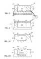
- FIGS. 2 a , 2 b , and 2 care cross-sectional views of the retracted, extended, and user input modes of the preferred embodiments, respectively.
- FIG. 3is a cross-sectional view of the sheet, the cavity, the sensor, and the display of the preferred embodiments with a processor.
- FIG. 4is a cross-sectional view of the sheet split into a layer portion and a substrate portion.
- FIGS. 5 a and 5 bare cross-sectional views of the sheet, the cavity, the sensor, and a displacement device that modifies the existing fluid in the cavity, with the cavity in a retracted volume setting and an expanded volume setting, respectively.
- FIG. 6is a schematic view of the sheet, the cavity, the sensor, and a displacement device of a first example that displaces additional fluid into the cavity.
- FIG. 7is a schematic view of the sheet, the cavity, the sensor, and a displacement device of a second example that displaces additional fluid into the cavity.
- FIGS. 8 a and 8 bare schematic views of the sheet, the cavity, the sensor, and a displacement device of a third example that displaces additional fluid into and out of the cavity, with the cavity in a retracted volume setting and an expanded volume setting, respectively.
- FIGS. 9 a , 9 b , 10 a , 10 b , 11 a , 11 b , 12 a , and 12 bare top and side views of a button deformation, a slider deformation, a slider ring deformation, a guide deformation, and a pointing stick deformation, respectively.
- FIG. 13is a cross-sectional view of a variation of the preferred embodiments with a support structure and a sensor that detects user touch through the support structure.
- FIGS. 14 a , 14 b , 14 c , and 14 dare schematic views of a first, second, third, and fourth example of a first variation of the sensor as a capacitive sensor, respectively.
- FIGS. 15 a and 15 bare schematic representations of a first and second method of measuring capacitance of a first variation of the sensor as a capacitive sensor, respectively.
- FIGS. 16 a , 16 b , and 16 care schematic views of a first, second, and third example of the placement of the conductors of the sensor as a capacitive sensor, respectively.
- FIGS. 17 a and 17 bare schematic views of a first and second example of a second variation of the sensor as a capacitive sensor, respectively.
- FIGS. 18 a - 18 eare schematic representations of a variety of geometries for the sensor as a capacitive sensor.
- FIGS. 19 a and 19 bare schematic views of a first and second variation of the sensor as a pressure sensor, respectively.
- FIG. 20is a flow chart of the different operation modes of the preferred embodiments.
- FIGS. 21 a - 21 dis a schematic of the different input graphics, different cavity settings, and different user touches of the preferred embodiments.
- FIGS. 22 and 23are schematic representations of variations of conductor arrangements in the variation of the user interface system including a second cavity.
- FIG. 22is a top view of the sensor that is a capacitive sensor with an X-conductor and a Y-conductor per cavity.
- FIG. 23is a top view of the sensor that is a capacitive sensor with fewer than an X-conductor and a Y-conductor per cavity.
- FIGS. 24 a and 24 bare cross-sectional views of a support member between the layer and the substrate, with the cavity in a retracted volume setting and an expanded volume setting, respectively.
- FIG. 24 cis a top view of the support member.
- FIG. 24 dis a cross-sectional view of an alternative support member that partially defines the cavity.
- the user interface system 100 of the preferred embodimentsincludes a sheet 110 that defines a surface 115 and a cavity 125 , a volume of a fluid 120 contained within the cavity 125 , a displacement device 130 that modifies the volume of the fluid 120 to expand the cavity 125 (thereby outwardly deforming a particular region 113 of the surface 115 ), and a sensor 140 that detects a force applied by a user that inwardly deforms the particular region 113 of the surface 115 .
- a sheet 110that defines a surface 115 and a cavity 125
- a volume of a fluid 120 contained within the cavity 125a displacement device 130 that modifies the volume of the fluid 120 to expand the cavity 125 (thereby outwardly deforming a particular region 113 of the surface 115 )
- a sensor 140that detects a force applied by a user that inwardly deforms the particular region 113 of the surface 115 .
- the user interface system toomay also include a display 150 coupled to the sheet 110 and adapted to output images to the user and a processor 160 that is preferably coupled to the sensor 140 to receive signals from the sensor 140 and coupled to the displacement device 130 to send signals to the displacement device 130 .
- the sensor 140may also be located in between the sheet 110 and the display 150 .
- any other suitable arrangement of the components of the system toomay be used.
- the user interface system too of the preferred embodimentshas been specifically designed to be used as the user interface for an electronic device, more preferably in an electronic device that benefits from an adaptive user interface.
- the electronic devicewhich may or may not include a display, may be an automotive console, a desktop computer, a laptop computer, a tablet computer, a television, a radio, a desk phone, a mobile phone, a PDA, a personal navigation device, a personal media player, a camera, a watch, a remote, a mouse, a trackpad, or a keyboard.
- the user interface system toomay, however, be used as the user interface for any suitable device that interfaces with a user in a tactile and/or visual manner. As shown in FIG.
- the surface 115 of the user interface system toopreferably remains flat until a tactile guidance is to be provided at the location of the particular region 113 .
- the surface 115 of the user interface system 100may also be deformed when a user input is required.
- the displacement device 130expands the cavity 125 to deform and/or expand the particular region 113 outward, preferably forming a button-like shape.
- the button-like shapethe user will have tactile guidance when navigating for the expanded particular region 113 and will have tactile feedback when applying force onto the particular region 113 to provide input.
- the sensor 140preferably senses the force that inwardly deforms the particular region 113 .
- any other arrangement of the user interface system 100 suitable to providing tactile guidance and/or detecting user inputmay be used.
- the sheet 110 of the preferred embodimentfunctions to provide the surface 115 that interfaces with a user in a tactile manner and to at least partially define the cavity 125 .
- the surface 115is preferably continuous, such that when swiping a finger across the surface 115 a user would not feel any interruptions or seams. Alternatively, the surface 115 may include features that facilitate the user in distinguishing one region from another.
- the surface 115is also preferably planar.
- the surface 115is preferably arranged in a flat plane, but may alternatively be arranged in a curved or warped plane.
- the surface 115also functions to deform upon an expansion of the cavity 125 , and to preferably “relax” or “un-deform” back to a normal planar state upon retraction of the cavity 125 .
- the sheet 110contains a first portion that is elastic and a second portion that is relatively less elastic.
- sheet 110is relatively more elastic in specific areas and relatively less elastic in other areas and is deformed by the expanded cavity 125 in the relatively more elastic areas.
- the sheet 110is generally of the same elasticity.
- the sheet 110includes or is made of a smart material, such as Nickel Titanium (commonly referred to as “Nitinol”), that has a selective and/or variable elasticity.
- the sheet 110is preferably optically transparent, but may alternatively be translucent or opaque. In addition to the transparency, the sheet 110 preferably has the following properties: a high transmission, a low haze, a wide viewing angle, a minimal amount of back reflectance upon the display (if the display is included with the user interface system too), scratch resistant, chemical resistant, stain resistant, relatively smooth (not tacky) to the touch, no out-gassing, and/or relatively low degradation rate when exposed to ultraviolet light.
- the sheet 110is preferably made from a suitable elastic material, including polymers and silicon-based elastomers such as poly-dimethylsiloxane (PDMS) or RTV Silicon (e.g., RTV Silicon 615).
- PDMSpoly-dimethylsiloxane
- RTV Silicone.g., RTV Silicon 615
- the inelastic portionis preferably made from a material including polymers or glass, for example, elastomers, silicon-based organic polymers such as poly-dimethylsiloxane (PDMS), thermoset plastics such as polymethyl methacrylate (PMMA), photocurable solvent resistant elastomers such as perfluropolyethers, polyethylene terephthalate (PET), or any other suitable material.
- PDMSpoly-dimethylsiloxane
- PMMApolymethyl methacrylate
- PETpolyethylene terephthalate
- the sheet 110may, however, be made of any suitable material that provides the surface 115 that deforms and defines a cavity 125 .
- the sheet 110may be manufactured using well-known techniques for micro-fluid arrays to create one or more cavities and/or micro channels.
- the sheet 110may be constructed using multiple layers from the same material or from different suitable materials, for example, the sheet 110 may include a layer portion 116 of one material that defines the surface 115 and a substrate portion 118 of a second material (as shown in FIG. 4 ).
- the substrate portion 118functions to support the layer portion 118 and to at least partially define the cavity 125 .
- any other suitable arrangement, material, and manufacturing methodmay be used to create sheet no.
- the substrate 120may include a lattice-like support member 112 under the particular region of the surface 115 .
- the support member 112functions to prevent a user from “pressing too far” into the deformation below the plane of the surface 115 .
- the support member 112functions to reduce (or potentially eliminate) the user from feeling “divots” in the surface 115 when swiping a finger across the surface 115 . As shown in FIG.
- the support member 112preferably includes holes or channels that allow for the expansion of the cavity 125 and the deformation of the surface 115 .
- the support member 112is preferably integrally formed with the substrate 124 , but may alternatively be formed with the layer 110 or may be separately formed and later attached to the substrate 120 .
- the support member 112may alternatively partially define the cavity 125 .
- the substrate 120is preferably rigid, but may alternatively be flexible in one or more directions.
- the substrate 120—if located above the display 150 —is preferably optically transparent, but may—if located below the display 150 or if bundled without a display 150 —be translucent or opaque.
- the substrate 120is preferably made from a material including polymers or glass, for example, elastomers, silicon-based organic polymers such as poly-dimethylsiloxane (PDMS), thermoset plastics such as polymethyl methacrylate (PMMA), and photocurable solvent resistant elastomers such as perfluropolyethers.
- the substrate 120may, however, be made of any suitable material that supports the layer 110 and at least partially defines the cavity 125 .
- the substrate 120is a single homogenous layer approximately 1mm to 0.1mm thick and can be manufactured using well-known techniques for micro-fluid arrays to create one or more cavities and/or micro channels.
- the substrate 120may be constructed using multiple layers from the same material or from different suitable materials.
- the cavity 125 of the preferred embodimentfunctions to hold a volume of fluid 120 and to have at least two volumetric settings: a retracted volume setting (shown in FIG. 2 a ) and an extended volume setting (shown in FIG. 2 b ).
- the fluid 120is preferably a substantially incompressible fluid, but may alternatively be a compressible fluid.
- the fluid 120is preferably a liquid (such as water, glycerin, or ethylene glycol), but may alternatively be a gas (such as air, nitrogen, or argon) or any other substance (such as a gel or aerogel) that expands the cavity 125 and deforms the surface 115 .
- the cavity 125deforms the particular region 113 of the surface 115 above the plane of the other regions of the surface 115 .
- the cavity 125preferably has a diameter of 2-10 mm.
- the cavity 125may have any suitable dimension.
- the displacement device 130 of the preferred embodimentfunctions to influence the volume of the fluid 120 to expand the cavity 125 from the retracted volume setting to the extended volume setting and, ultimately, deforming a particular region 113 of the surface 115 .
- the displacement device 130preferably modifies the volume of the fluid 120 by (1) modifying the volume of the existing fluid in the cavity 125 , or (2) adding and removing fluid to and from the cavity 125 .
- the displacement device 130may, however, influence the volume of the fluid 120 by any suitable device or method. Modifying the volume of the existing fluid in the cavity 125 most likely has an advantage of lesser complexity, while adding and removing fluid to and from the cavity 125 most likely has an advantage of maintaining the deformation of the surface 115 without the need for additional energy (if valves or other lockable mechanisms are used).
- the displacement device 130When used with a mobile phone device, the displacement device 130 preferably increases the volume of the fluid 120 within the cavity 125 by approximately 0.003-0.1 ml. When used with this or other applications, however, the volume of the fluid may be increased (or possibly decreased) by any suitable amount.
- the heating elementwhich may be located within, adjacent the cavity 125 , or any other location suitable to providing heat to the fluid, is preferably a resistive heater (made of a material such as TaN or Nichrome).
- the fluidmay include an expandable substance, such as plastic expandable microspheres.
- the fluidmay include paraffin. While these are three examples, the displacement device 130 can be any other suitable device or method that ultimately expands the cavity 125 from the retracted volume setting to the extended volume setting by modifying the existing fluid in the cavity 125 .
- the displacement device 130includes a reservoir 132 to hold additional fluid and a pump 134 to displace fluid from the reservoir 132 to the cavity 125 .
- the reservoir 132is preferably remote from the cavity 125 (and connected by a channel 138 or other suitable device), but may alternatively be located adjacent the cavity 125 and connected directly to the cavity 125 .
- a portion of the channel 138is preferably a micro-fluidic channel (having cross-section dimensions in the range of 1 micrometer to 1000 micrometers), but depending on the size and costs constraints of the user interface system 100 , the channel 138 may have any suitable dimensions.
- the pump 134is preferably a micro-pump (such as pump #MDP2205 from ThinXXS Microtechnology AG of Zweibrucken, Germany or pump #mp5 from Bartels Mikrotechnik GmbH of Dortmund, Germany), but may be any suitable device to pump fluid from one location to another.
- the pump 134is preferably located at a distance from the cavity 125 , and is preferably connected to the cavity 125 by a channel 138 . To extend the cavity 125 from a retracted volume setting to the extended volume setting, the pump 134 displaces fluid from a reservoir 132 , through the channel 138 , and into the cavity 125 .
- the pump 134preferably “vents” or pumps in a reverse direction from the cavity 125 to the reservoir 132 .
- the displacement device 130includes a reservoir 132 to hold additional fluid, a first pump 134 to displace fluid from the reservoir 132 to the cavity 125 , a second pump 136 to displace fluid from the cavity 125 to the reservoir 132 , a first valve located between the first pump 134 and the cavity 125 , and a second valve located between the cavity 125 and the second pump 136 .
- the first valveis opened, the second valve is closed, and the first pump 134 displaces fluid from the reservoir 132 , through the channel 138 , and into the cavity 125 .
- the first valveis closed, the second valve is opened, and the second pump 136 displaces fluid from the cavity 125 , through the channel 138 , and into the reservoir 132 .
- the second exampleis similar to the first example above.
- the user interface system 100may omit the second pump 136 and simply retract the cavity 125 from the extended volume setting to the retracted volume setting by opening the second valve and allowing the cavity 125 to vent or “drain” into the reservoir 132 (potentially assisted by the elasticity of the sheet 110 returning to an un-deformed state).
- the displacement device 130includes an actuator, such as a linear actuator, that displaces fluid into and out of the cavity 125 .
- the linear actuatordisplaces fluid through the channel 138 and into the cavity 125 .
- the linear actuatordraws fluid in a reverse direction from the cavity 125 to the reservoir 132 .
- the displacement device 130can be any other suitable device or method that ultimately expands the cavity 125 from the retracted volume setting to the extended volume setting by adding and removing fluid to and from the cavity 125 .
- the cause of the deformation of a particular region 113 of the surface 115has been described as a modification of the volume of the fluid in the cavity 125 , it is possible to describe the cause of the deformation as an increase in the pressure below the surface 115 relative to the pressure above the surface 115 .
- an increase of approximately 0.1-10.0 psi between the pressure below the sheet 110 relative to the pressure above the sheet nois preferably enough to deform a particular region 113 of the surface 115 .
- the modification of the pressuremay be increased (or possibly decreased) by any suitable amount.
- the deformation of the particular region 113functions to provide tactile feedback and tactile guidance on the surface 115 for the user.
- the deformation of the particular region 113also preferably functions to inform the user of the type of input the deformation represents.
- the deformation of the particular region 113may be of a shape that indicates the type of input that the deformation represents.
- a circular deformationmay indicate to the user that they are to select an area along the circular deformation.
- the sheet 110may include tactile instructions, for example, a pattern of beads on the particular region 113 that indicate the type of input the deformation represents, for example, a deformation may have a tactile pattern of beads that indicate an arrow, informing the user that the deformation is for a directional input.
- the tactile instructions on the particular region 113may alternatively be any other type of feature that is able to be felt tactilely by the user.
- the sheet 110 of the user interface 100may also be coupled to a graphic (e.g, a paper insert, a photo, etc.) to indicate to the user the input that is associated with depressing the deformed particular region 113 .
- a graphice.g, a paper insert, a photo, etc.
- the useris preferably shown at least one image that is an image of a visual guide or an input key that is substantially aligned with the particular region 113 .
- the display 150may also display at least two images, with at least one image substantially aligned with the particular region 113 and functioning to visually differentiate the particular region 113 from the rest of the surface 115 and indicating a visual guide or an input key that the deformed particular region 113 represents. From the user's perspective, the device is asking for a user input through the display 150 and the user interface system 110 is providing tactile guidance and tactile feedback when the user indicates the desired input.
- the two imagesmay alternatively include a first image and a second image. The first image is displayed and substantially aligned with the particular region 113 and then the second image is displayed and substantially aligned with the particular region 113 when the first image is removed.
- any other arrangement of the user interface system 100 suitable to interfacing with the usermay be used.
- the deformationpreferably acts as (1) a button that, when pressed by the user, signals an input to the sensor 140 (2) a slider that may be pressed at multiple points along the deformation by the user and that signals the location of multiple inputs on the sensor 140 , and/or (3) a pointing stick that signals the location of multiple inputs on sensor 140 .
- the deformationmay, however, act as any other suitable device or method that signals a user input to the sensor 140 .
- the buttonas shown in FIGS. 9 a and 9 b , preferably has a dome-like shape, but may alternatively have a cylindrical-like shape (with a flat top surface), a pyramid-like shape, a cube-like shape (with a flat top), or any other suitable button shape.
- the sensor 140preferably recognizes any user touch 145 into the button as a user input.
- the slideras shown in FIGS. 10 a , 10 b , 11 a and 11 b , preferably has a ridge like shape (shown in FIGS. 10 a and 10 b ), but may alternatively have a ring like shape (shown in FIGS. 11 a and 11 b ), a plus-like shape, or any other suitable slider shape.
- the sensor 140preferably recognizes user touches 145 at different locations into the slider and distinguishes these user touches as different user inputs.
- the slider with the ring like shapemay act like the “click wheel” of the Apple iPod (second generation).
- the pointing sticklike the button, preferably has a dome-like shape, as shown in FIGS. 12 a and 12 b , but may alternatively have a cylindrical-like shape (with a flat top surface), a pyramid-like shape, a cube-like shape (with a flat top), or any other suitable button shape.
- the sensor 140preferably recognizes user touches 145 at different locations along the pointing stick and distinguishes these user touches as different user inputs.
- a depression from the force applied by the user on a portion of the pointing stickis meant to signal a user input in the location of the depression relative to the geometry of the pointing stick.
- a depression by the user in the upper right quadrantwill be interpreted differently than a depression by the user in the lower right quadrant.
- the usermay depress the pointing stick in a sweeping motion, for example, a “sweep” from the upper right quadrant to the lower right quadrant. This may be interpreted as a moving input, similar to that seen in the “click wheel” of the Apple iPod (second generation).
- the point stickmay act like the pointing stick trademarked by IBM as the TRACKPOINT and by Synaptics as the TOUCHSTYK (which are both informally known as the “nipple”).
- the sensor 140may be located within the cavity 125 and/or adjacent to the cavity 125 , but may alternatively be located in any other suitable location.
- a sensor 140preferably functions to sense a user input through the support element 112 from any location.
- the sensor 140preferably detects the presence of a user touch, an inward depression of the expanded particular region 113 , and/or any other suitable user input.
- the sensor may 140may also function to detect the direction of the user input, the location of the user input, the rate at which the user is inwardly deforming the expanded particular region 113 , the level to which the user is inwardly deforming the expanded particular region 113 , the type of user input (for example, input by finger or by stylus), and/or any other suitable characteristic of the user input.
- the sensor 140is preferably a capacitive sensor that includes at least two conductors that detects a fluctuation in an electric field created by the at least two conductors of the capacitive sensor.
- the fluctuationmay be caused by a user touch, user input through a stylus or any other suitable input assist element, the deformation of the particular region 113 , change in fluid position/volume, or any other event that may cause a fluctuation in the electric field that may result in a change in the measured capacitance.
- the capacitive sensorand is preferably one of several variations. In a first variation, the capacitive sensor includes a first conductor 142 and a second conductor that is a virtual conductor.
- the virtual conductormay be the virtual ground (such as the shielding ground or the case ground) of the device that the user interface system 100 is appended to, a screen ground for the display 150 , or, if the device is a cellular phone, the RF/Signal ground of the device. Fluctuations in the electric field generated between the first conductor 142 and the virtual ground may be used to detect the presence of touch or an input.
- the capacitive sensoris adapted to sense height changes of the fluid 120 within the cavity 125 and/or the presence of a finger on the deformed particular region 113 . As shown in FIG.
- the first conductor 142is preferably placed in a location within or adjacent the cavity wherein the inward deformation of the particular region 113 will change the height of the fluid 120 relative to the first conductor 142 , thereby influencing the measured capacitance of the capacitive sensor.
- the first conductor 142is preferably located on the bottom side of the cavity opposite of the surface 115 , allowing the capacitive sensor to sense height changes of the fluid as the particular region 113 is inwardly deformed, but may alternatively be located at the side of the cavity adjacent to the surface 115 .
- the first conductor 142When placed adjacent to the surface 115 , the first conductor 142 preferably deforms with the particular surface 113 as the user applies force to allow a change in the height of fluid 120 to be sensed.
- the first conductor 142may alternatively be placed in any suitable location to allow changes in the height of fluid 120 due to inward deformation of the particular surface 113 to be sensed.
- the first conductor 142is preferably made of copper, micro or nanowire, or a transparent conductor such as sputtered indium tin oxide (ITO), but may alternatively be of any type of conductive material wherein the measured capacitance of the conductor is sensitive to height changes of the fluid 120 .
- the capacitive sensormay also function to detect a capacitance change relative to the surface 115 due to the presence of the finger of the user.
- capacitive sensor of the first variationmay include a first conductor 142 and a second conductor 144 that is placed within the cavity 125 .
- the second conductor 144may be used measure the change in capacitance in between the first conductor 142 and the second conductor 144 as the user inwardly deforms the particular region 113 .
- the amount of fluid 120 and/or the height of the fluid 120 in between the first conductor 142 and the second conductor 144may change, causing a change in measured capacitance in between the first conductor 142 and the second conductor 144 .
- the gradient of height difference in between the first conductor 142 and the second conductor 144may also yield a measurable change in the capacitance in between the first conductor 142 and the second conductor 144 .
- the capacitance reading between the first conductor 142 and the second conductor 144 when the user inwardly deforms the particular region 113 closer to the first conductor 142may be different from the capacitance reading between the first conductor 142 and the second conductor 144 when the user inwardly deforms the particular region 113 closer to the second conductor 144 .
- This differencemay facilitate determining the location of the user input relative to the geometry of the particular region 113 .
- the second conductor 144may be used to measure height changes of the fluid 120 in the region above the second conductor 144 to work in tandem with the first conductor 142 to provide a more local capacitive measurement of height changes within the cavity 125 . Measuring local capacitive changes within the cavity 125 also allows a relative height difference in the fluid 120 to be measured. For example, as the user inwardly deforms the particular region 113 , the height of the fluid 120 over the first conductor 142 may be different from the height of the fluid over the second conductor 144 , resulting in a difference in the measured capacitance value of the first conductor 142 and the measured capacitance value of the second conductor 144 relative to the surface 115 .
- the capacitance between the first conductor 142 and a first portion of the second conductor 144may also be compared to the capacitance between the first conductor 142 and a second portion of the second conductor 144 to determine the relative difference in the height of the fluid 120 .
- the relative difference in capacitive values between the two conductors 142 and 144may facilitate the determination of the location of the user input relative to the geometry of the particular region 113 .
- the first and second portions of the second conductor 144may be continuous sections along the second conductor 144 , but may alternatively be separated by a third portion of a different material from the first and second portions or a break in the second conductor 144 .
- the second conductor 144may include the first portion and also include a third conductor 146 that contains the second portion. However, any other suitable arrangement and method to determine the occurrence and/or location of a user input through the conductors may be used.
- the second conductor 144is preferably identical to the first conductor 142 in material and manufacturing, but may alternatively be made of any material or method suitable to providing a capacitive relationship with the first conductor 142 .
- the capacitive sensor of the first variationmay also include a third conductor 146 and/or a fourth conductor 148 .
- the addition of a third and/or fourth conductor 146 and 148allows for more accurate determination of the location of user input relative to the geometry of the particular region 113 .
- the particular region 113may be divided into a four quadrant coordinate system through an X and Y axis with the origin substantially in the center of the particular region 113 .
- the location of the user input relative to the geometry of the particular region 113may be measured in a variety of methods. In a first method, as shown in FIG.
- the capacitance and/or the relative capacitance between the first conductor 142 and the third conductor 146may be measured to determine the location of the user input along the X-axis and the capacitance and/or the relative capacitance between the second conductor 144 and the fourth conductor 148 may be measured to determine the location of the user input along the Y-axis.
- the measured location along the X-axis and the measured location along the Y-axisare then used to determine the location of the user input within the four quadrant coordinate system.
- a second methodas shown in FIG.
- three capacitance and/or relative capacitance valuesare measured: between the first conductor 142 and the second conductor 144 , between the first conductor 142 and the third conductor 146 , and between the first conductor 142 and the fourth conductor 148 .
- the three capacitance valuesare then preferably used to determine the location of the user input within a four quadrant coordinate system (which can be superimposed over the “tridrant” coordinate system).
- the same methods and/or relationshipsmay be applied to the case of three conductors or any other suitable number of conductors.
- any suitable number of conductors and any other method or relationship between the conductors suitable to determine the location of the user input relative to the geometry of the particular region 113may be used.
- the third conductor 146 , fourth conductor 148 , and/or any other suitable number of conductorsare preferably identical to the first conductor 142 in material and manufacturing, but may alternatively made of any material or method suitable to providing a capacitive relationship with the first conductor 142 and/or other conductors.
- the first conductor 142is preferably placed at a first level relative to the cavity and the second, third, fourth conductors 144 , 146 , 148 , and/or any other suitable number of conductors are placed at the same level relative to the cavity.
- the first conductor 142may be placed at a first level relative to the cavity and the second conductor 144 may be placed at a second level relative to the cavity.
- the second levelis preferably higher than the first level, but may alternatively be lower than the first level.
- the third, fourth conductors 146 , 148 and/or any other suitable number of conductorsmay also be placed at the second level, but may alternatively be located at a third and/or fourth level relative to the cavity.
- the difference in location placement relative to the height level within the cavitymay facilitate accurate measurement of the location of user input relative to the geometry of the particular region 113 .
- the first conductor 142may be coupled to the substrate portion 118 and the second conductor 144 may be coupled to the layer portion 116 , as shown in FIG. 16 c .
- any other combination of placement of the conductors of the capacitive sensor suitable to determining the location of the user input relative to the geometry of the particular region 113may be used.
- the capacitive sensor of the second variationpreferably senses the change in height in between a first conductor 142 and a second conductor 144 .
- the first conductor 142is preferably placed in a location that moves when the user inwardly deforms the particular region 113 and the second conductor 144 is preferably placed in a location that remains relatively stationary when the user inwardly deforms the particular region 113 .
- the second conductor 144may be placed within the cavity 125 , as shown in FIG. 17 a , but may alternatively be placed in any relatively stationary location within the user interface system 100 , as shown in FIG. 17 b .
- the first conductor 142may also be a flexible conductor such that the inward deformation of the particular region 113 may cause the first conductor 142 to similarly deform. This may allow the location of the user input relative to the geometry of the particular region 113 to be determined.
- the capacitive sensormay also include a third conductor 146 and/or any suitable number of conductors that may facilitate accurately determining the location of the user input relative to the geometry of the particular region 113 .
- the movement of the first conductor 142may be detected by measuring the capacitive value between the first conductor 142 and the second conductor 144 and the capacitive value between the first conductor 142 and the third conductor 146 .
- the difference between the two capacitive valuesmay better indicate the location of the user input relative to the geometry of the particular region 113 .
- the capacitance between the first conductor 142 and a first portion of the second conductor 144may also be compared to the capacitance between the first conductor 142 and a second portion of the second conductor 144 to determine the relative difference in the height of the fluid 120 .
- the relative difference in capacitive values between the two conductors 142 and 144may facilitate the determination of the location of the user input relative to the geometry of the particular region 113 .
- any other suitable arrangement and location of the conductors of the capacitive sensor of the second variation of the sensor 140 suitable to measuring distance differences between conductors due to inward deformation of the particular region 113 by the usermay be used.
- the conductors of the second variationare preferably identical to the first conductor 142 in the first variation in material and manufacturing, but may alternatively made of any material or method suitable to providing a capacitive relationship indicating the distance between conductors.
- the conductors of the capacitive sensor variation of the sensor 140may be any one of a variety of arrangements and geometries.
- both the first and second variations of the capacitive sensormay include at least two conductors (a first conductor and a second conductor).
- the first and second conductorsare preferably of the same shape within the cavity 125 .
- the first conductormay be of a first geometry and the second conductor may be of a second geometry to increase accuracy in measuring changes in capacitance due to inward deformation of the particular region 113 by the user.
- the second geometrymay follow the geometry of the particular region 113 to facilitate the detection of deformations of the particular region 113 , as shown in FIGS. 18 b and 18 c .
- the second conductormay be placed substantially close to the perimeter of the particular region 113 , but may alternatively be placed substantially close to the center of the particular region 113 .
- the second conductormay be placed in any location suitable to detecting the desired user inputs.
- the second conductormay be placed perpendicular to the first conductor to allow deformations to be detected both along the axis of the first conductor and along the axis of the second conductor, expanding the region of sensitivity.
- the second conductormay contain more than one portion wherein the capacitance between the first conductor and a first portion of the second conductor is compared to the capacitance between the first conductor and a second portion of the second conductor.
- any suitable arrangement or geometry of the first and second conductorsmay be used.
- the sensor 140may alternatively be a resistance sensor. Similar to the capacitive sensor, the resistance sensor preferably has at least two conductors and functions to measure the resistance in between the two conductors. In an example, the two conductors may be placed in two different locations within the cavity 125 . The resistance between the two conductors may be of a first value in the retracted state and the resistance between the two conductors may be of a second value in the expanded state. When a user provides a force to inwardly deform the deformed particular region 113 , the resistance between the two conductors may be of a third value that may be in between the first and the second value. This reading may be used to determine the occurrence of inward deformation of the expanded particular region 113 , but may also be used to determine the degree of inward deformation of the expanded particular region 113 caused by the user.
- the sensor 140may alternatively be a pressure sensor, as shown in FIG. 19 a .
- the fluid 120is preferably of a volume that substantially fills the cavity 125 and is also preferably of a substantially incompressible fluid (e.g. water, oil), but may be of any other volume or fluid type wherein inward deformation of the particular region 113 will cause a measurable change in the volume of fluid 120 within the cavity 125 .
- the pressure sensorpreferably measures an increase in the pressure within cavity 125 when there is an inward deformation of the particular region 113 .
- the pressure sensoris preferably an absolute pressure sensor, but may also be a differential pressure sensor or any other suitable type of pressure sensor.
- the pressure sensormay alternatively be a strain gauge mounted within and partially defining the cavity, which deforms when there is an inward deformation of the particular region 113 .
- the pressure sensor of the sensor 140may, however, be of any suitable type to measure pressure change within the cavity 125 due to inward deformation of the particular region 113 .
- the sensor 140may alternatively be a flow sensor.
- the flow sensorpreferably measures backflow of the fluid 120 .
- the cavity 125is preferably coupled to a channel 138 .
- the flow sensorpreferably detects and/or measures the backflow of the fluid 120 through the channel 138 to determine the occurrence of a deformation of the particular region 113 and/or the magnitude of deformation of the particular region 113 .
- the flow sensoris preferably placed in a location in the channel 138 wherein fluid flow is only seen when there is backflow due to the inward deformation of the particular region 113 .
- the channel 138may also include a valve 122 that is normally closed to maintain a constant volume of fluid 120 within the cavity. When there is inward deformation of the particular region 113 , the valve 122 is opened, allowing backflow to the rest of the channel 138 .
- the flow sensormay be a flow rate sensor that measures the flow rate of the fluid.
- the volume of fluid 120 that flows through the channel 138may be calculated from the known cross sectional area of the channel 138 and the flow rate.
- valve 122 and/or sensor 140are shown to be located in relatively close proximity to the cavity 125 in FIG. 19 b .
- the valve 122 and/or sensor 140may be placed in any other suitable location relative to the cavity 125 (for example, in a region not pictured in FIG. 19 b ), that enables contact with fluid flowing through the channel 138 .
- the pressure sensormay alternatively be a Hall effect sensor or any other type of sensor that senses the opening of the valve 122 due to the backflow of the fluid 120 .
- the flow sensormay be any other type of fluid sensor that is able to detect and/or measure backflow of the fluid 120 .
- the sensor 140may alternatively be a strain sensor.
- the strain gage sensorpreferably measures the strain of the particular region 113 of the surface 115 .
- the strain sensoridentify when the particular region of the surface has been depressed in the extended volume setting.
- a plurality of strain sensorsmay facilitate determining the location of the user input relative to the particular region 113 .
- Multiple strain gaugesmay be coupled either on, under, or within the surface, and the difference in deformation of one portion of the surface relative to another may help indicate the location of the user input relative to the particular region 113 .
- the capacitive, the resistance, the pressure, the flow, and the strain sensor variations of the sensor 140may allow the location of a user input or a shift in the location of user input along the deformation of the particular region 113 (e.g., as the user “sweeps” from one location to another) to be detected, the sensor 140 of these variation may be applied to the slide and the pointing stick variations of the deformation of the particular region 113 described above.
- the sensor 140is preferably one of the variations described above, but may be any other sensor suitable to sensing the inward deformation of the particular region 113 .
- the sensor 140may also be of any suitable combination of the variations described above.
- the user interface system 100 of the preferred embodimentmay also include a processor, which is coupled to the displacement device 130 and to the sensor 140 .
- the processor 160functions to operate the user interface system 100 in an Extended Cavity Mode and a Retracted Cavity Mode.
- a force of a first degree or magnitude applied by the user onto the deformed particular region of the surface 113is preferably recognized as a user input of a first type.
- a force of a second degree or magnitude applied by the user onto the deformed particular region 113 of the surface, wherein the second degree is less than the first degree,is preferably recognized as a user input of a second type.
- the processor 160if the force of the second degree is the result of the user resting his or her finger on the particular region 113 , then the processor 160 preferably ignores the user input of the second type. In this manner, the deformation of the particular region 113 additionally functions to distance the user touch from the sensor 140 and to allow the user to rest their fingers on the deformation (the location of an input) without actuating the input.
- the processor 160may interpret the user input of the second type as an input of a lower magnitude than the user input of the first type.
- any other suitable relationship between the user input of the first type and the second typemay be applied.
- the determination of whether the force applied by the user on the particular region 113 is of the first degree or the second degreemay be set or modified by the manufacturer, the processor, and/or the user.
- a user touch at the particular region in the surface 115is preferably not recognized as a user input of the first type or the second type, but rather as a user input of a third type that is distinguishable from a user input of the first type and the second type. The user input of the third type may also be ignored.
- a force applied by the user of a third degreemay be interpreted as a user input of a fourth type.
- any additional degrees of force applied by the user on the particular region 113may be detected and interpreted as any suitable type of user input.
- the processor 160may also function to detect the rate at which the user applies a force to the particular region 160 .
- a force applied at a first rate of change onto the deformed particular region of the surface 113is preferably recognized as a user input of a first type.
- An applied force of a second rate of change onto the deformed particular region 113 of the surface, wherein the second rate is higher than the first rate,is preferably recognized as a user input of a second type.
- the inward deformation of the particular region 113may be interpreted by the processor 160 as an indication of the user to scroll through a webpage.
- the processorWhen the user applies a force at the first rate, the processor will scroll through the webpage at a first speed. When the user applies a force at the second rate, then the processor will scroll through the website at a second speed, wherein the second speed is faster than the first speed. In this manner, the sensor 140 and the processor 160 are able to determine a larger range of user inputs from the inward deformation of the particular region 113 . However, any other suitable relationship between the user input of the first type and the second type may be applied. The question of whether the force applied by the user on the particular region 113 is of the first rate or the second rate may be set or modified by the manufacturer, by the processor, or by the user.
- a user touch at the particular region in the surface 115is preferably not recognized as a user input of the first type or the second type, but rather is recognized as a user input of a third type that is distinguishable from a user input of the first type and the second type.
- the user input of the third typemay also be ignored.
- a force applied by the user of a third rate of changewherein the third rate is higher than the first rate but lower than the second rate, may be interpreted as a user input of a fourth type.
- any additional rate of change of force applied by the user on the particular region 113may be detected and interpreted as any suitable type of user input.
- the processor 160may also function to automatically alter the settings of the user interface system 100 .
- the processor 160may be coupled to a temperature sensor and may disable the displacement device 130 under such conditions.
- the processor 160may be coupled to a pressure sensor and may either disable the displacement device 130 , or may simply adjust the volume of the fluid that is modified under such conditions.
- the processor 160may also be coupled to the display 150 such that different input graphics may be displayed under the particular region 113 , and different inputs may be recognized.
- the display 150may include an input graphic of a first type (such as a letter) and the user input on the deformation, as shown in FIG. 21 b , would be of a first type (such as a letter), and the display 150 may include an input graphic of a second type (such as a number) and the user input on the deformation would be of a second type (such as a number), as shown in FIG. 21 c .
- the display 150may further include an input graphic of a third type (such as an “enter” or “accept” input), and the user input on the sensor 140 would be of a third type (such as an “enter” or “accept” input), as shown in FIG. 21 d .
- the processor 160may also be coupled to the device upon which the display 150 and the user interface system 100 are used and may function to control processes carried out by the device.
- the processor 160may also function to alter the output of the display 150 to correct or adjust for any optical distortion caused by the deformation of the particular region 113 . It is envisioned that, in certain applications, the size of the deformation may cause a “fish eye” effect when viewing the display 150 .
- the processorpreferably through empirical data, may adjust the output to help correct for this distortion.
- the processor 160preferably includes a separate and remote controller for the displacement device 130 , a separate and remote controller for the sensor 140 , and a separate and remote controller for the display 150 .
- the processor 160may, however, integrally include a controller for one or more of these elements.
- the processor 160preferably performs one of the functions described above, but may also perform any combination of the functions described above or any other suitable function.
- the user interface system 100 of the preferred embodimentalso includes a second cavity 125 .
- the additional cavitiesmay be substantially identical to the cavity 125 , but may also be different in construction, geometry, size, and/or any other suitable feature.
- Each of the plurality of cavities 125are preferably able to outwardly deform independently from each other, allowing the user interface system 100 to be adapted to a variety of user input scenarios.
- the plurality of cavities 125may be grouped into a plurality of portions, wherein the cavities 125 within one group will outwardly deform together.
- the processor 160preferably selectively controls the outward deformation of the particular region 113 of each cavity 125 .
- any other suitable method of controlling the cavities 125may be used.
- the processor 160preferably also selectively receives and/or interprets signals representing the presence of a force applied by a user to any cavity 125 .
- the sensor 140 for each cavity 125is preferably arranged in an array network that preferably communicates the location of each sensor 140 to the processor 160 to allow the processor 160 to selectively receive and/or interpret signals coming from each cavity 125 .
- the arrayincludes a first number of X-conductors 142 and a second number of Y-conductors 144 . In a first variation, as shown in FIG.
- the first number of X-conductors 142is preferably equivalent to the number of cavities 125 , wherein each X-first conductor 142 corresponds to one cavity 125
- the second number of Y-conductors 144is preferably equivalent to the number of columns of cavities 125 , wherein each Y-conductor 144 corresponds to all the cavities 125 within one column of cavities 125 .
- the location of a user touchis preferably determined by detecting a change in the measured capacitance value between one X-first conductor 142 and the corresponding Y-conductor 144 for a particular cavity 125 .
- the processor 160is able to detect the location of the cavity 125 over which the user had applied a force.
- the first number of X-conductors 142is preferably equivalent to the number of rows of cavities 125 , wherein each X-first conductor 142 corresponds to all the cavities 125 within one row of cavities 125
- the second number of Y-conductors 144is preferably equivalent to the number of columns of cavities 113 , wherein each Y-conductor 144 corresponds to all the cavities 113 within one column of cavities 144 .
- the location of a user touchis preferably determined by detecting a change in the measured capacitance value between one X-first conductor 142 and one Y-conductor 144 . Because each cavity 125 corresponds to a different intersection of the X-conductors 142 and the Y-conductors 144 , the processor 160 is able to detect the location of the cavity 125 over which the user had applied force.
- the first number of X-conductors 142 and the second number of Y-conductors 144are both preferably equivalent to the number of cavities 125 , one X-first conductor 142 and one Y-conductor 144 correspond to one cavity 125 .
- the location of a user touchis preferably determined by detecting a change in the measured capacitance value between one X-first conductor 142 and one Y-conductor 144 . Because each cavity 125 corresponds to a different pair of the X-conductors 142 and the Y-conductors 144 , the processor 160 is able to detect the location of the cavity 125 over which the user had applied force.
- the array network of sensors 140may include a plurality of sensors 140 , each coupled to a cavity 125 , that each output a signal specific to the cavity 125 .
- the sensor 140 for a first cavity 125may send a signal of 0.5 nF when a user input is detected and a signal of 1 nF when no user input is detected
- the sensor 140 for a second cavity 125may send a signal of 5 nF when a user input is detected and a signal of 10 nF when no user input is detected
- the sensor 140 for a third cavity 125may send a signal of 50 nF when a user input is detected and a signal of 100 nF when no user input is detected
- the sensor 140 for a fourth cavity 125may send a signal of 500 nF when a user input is detected and a signal of 1000 nF when no user input is detected.
- each cavity 125sends a different signal
- the processor 160is able to detect the location of the user input based upon the type and/or value of the signal that is received from the sensors 140 .
- the plurality of sensors 140 for the cavities 125may also be arranged in a parallel relationship (such that the overall capacitive value for a plurality of capacitors in parallel equate to the sum of the individual capacitive values) to facilitate the processor 160 in sensing the location of the user input.
- the processor 160may receive a combined signal of 555.5 nF from the sensors 140 when a user input is detected from all of the first, second, third, and fourth cavities 125 and a signal of 1111 nF from the sensors 140 when no user input is detected from any of the first, second, third, and fourth cavities 125 .
- the combined signal to the processor 160may be 1061 nF.
- the combined signal to the processor 160may be 1056 nF.
- the processor 160is then able to interpret the locations of the user input directly from the value of the signal that is received from a plurality of sensors 140 of the cavities 125 , simplifying electrical routing, mechanical components, and programming in the user interface system 100 .
- the sensors 140may also be arranged in series or in any other suitable electrical arrangement.
- the array arrangements described abovealso provide the advantage of utilizing multiple sensors 140 to more accurately locate the presence of a user input.
- User input onto a first expanded particular region 113may affect the sensor 140 readings for a second expanded particular region 113 .
- the particular region 113 upon which the user provides an inputmay be more accurately determined.
- the sensor 140is a pressure sensor
- the pressure sensed by other sensors 140 within the systemmay be increased when a user provides input at a first particular region 113 .
- the array arrangements described aboveallows for multiple inputs provided at a single time to be detected by the system.
- the sensors 140are preferably located within the cavities 125 , but may alternatively be located adjacent to the cavities 125 or both within and adjacent to the cavities 125 . By placing sensors 140 both within and adjacent to the cavities 125 , user inputs provided to locations other than the particular regions 113 may also be detected, expanding the range of input types and query types for the device. Sensors 140 placed adjacent to the cavities 125 may also be used to more accurately locate the particular region 113 upon which the user provided the input.
- the sensor 140 , cavity 140 , and second cavity 140may are preferably in arranged in one of the variations described above, but may also be any combination of the variations described above. However, any other suitable arrangement or method of controlling the cavities 125 may be used.
- the user interface system 100 of the preferred embodimentsmay also include either a power source or a power harnessing device, which both function to power the displacement device 130 (and possibly other elements of the user interface system, such as the sensor 140 and/or the display 150 ).
- the power sourceis preferably a conventional battery, but may be any suitable device or method that provides power to the displacement device 130 .
- the power-harnessing devicewhich is preferably integrated into the hinge of a flip phone or laptop, functions to harness a portion of the energy involved in the normal use of the electronic device (such as the physical energy provided by the user in the opening of a flip phone or the screen on a laptop).
- the power-harnessing devicemay alternatively be integrated in a separate mechanical input device (such as a button on the side of a mobile phone, or a “self-winding” device found in automatic watches) or any other suitable device or method to harness a portion of the energy involved in the normal use of the electronic device.
- a separate mechanical input devicesuch as a button on the side of a mobile phone, or a “self-winding” device found in automatic watches
Landscapes
- Engineering & Computer Science (AREA)
- General Engineering & Computer Science (AREA)
- Theoretical Computer Science (AREA)
- Human Computer Interaction (AREA)
- Physics & Mathematics (AREA)
- General Physics & Mathematics (AREA)
- Position Input By Displaying (AREA)
Abstract
Description
Claims (44)
Priority Applications (31)
| Application Number | Priority Date | Filing Date | Title |
|---|---|---|---|
| US12/497,622US8179375B2 (en) | 2008-01-04 | 2009-07-03 | User interface system and method |
| US12/975,329US8922502B2 (en) | 2008-01-04 | 2010-12-21 | User interface system |
| US12/975,337US8922503B2 (en) | 2008-01-04 | 2010-12-21 | User interface system |
| US13/090,217US8970403B2 (en) | 2008-01-04 | 2011-04-19 | Method for actuating a tactile interface layer |
| US13/090,213US9013417B2 (en) | 2008-01-04 | 2011-04-19 | User interface system |
| US13/278,138US8928621B2 (en) | 2008-01-04 | 2011-10-20 | User interface system and method |
| US13/456,010US8947383B2 (en) | 2008-01-04 | 2012-04-25 | User interface system and method |
| US13/896,098US9052790B2 (en) | 2008-01-04 | 2013-05-16 | User interface and methods |
| US13/896,090US9063627B2 (en) | 2008-01-04 | 2013-05-16 | User interface and methods |
| US14/196,195US9019228B2 (en) | 2008-01-04 | 2014-03-04 | User interface system |
| US14/242,352US9372539B2 (en) | 2008-01-04 | 2014-04-01 | Method for actuating a tactile interface layer |
| US14/471,889US9298261B2 (en) | 2008-01-04 | 2014-08-28 | Method for actuating a tactile interface layer |
| US14/471,842US9423875B2 (en) | 2008-01-04 | 2014-08-28 | Dynamic tactile interface with exhibiting optical dispersion characteristics |
| US14/514,134US9207795B2 (en) | 2008-01-04 | 2014-10-14 | User interface system |
| US14/567,838US20150091870A1 (en) | 2009-07-03 | 2014-12-11 | User interface system |
| US14/575,826US9619030B2 (en) | 2008-01-04 | 2014-12-18 | User interface system and method |
| US14/597,576US9524025B2 (en) | 2008-01-04 | 2015-01-15 | User interface system and method |
| US14/635,304US9448630B2 (en) | 2008-01-04 | 2015-03-02 | Method for actuating a tactile interface layer |
| US14/691,344US9477308B2 (en) | 2008-01-04 | 2015-04-20 | User interface system |
| US14/697,414US20150253853A1 (en) | 2008-01-04 | 2015-04-27 | User interface system |
| US14/711,558US9495055B2 (en) | 2008-01-04 | 2015-05-13 | User interface and methods |
| US14/815,771US9588684B2 (en) | 2009-01-05 | 2015-07-31 | Tactile interface for a computing device |
| US14/821,526US20160188068A1 (en) | 2009-01-05 | 2015-08-07 | Tactile interface for a computing device |
| US14/927,859US20160054833A1 (en) | 2008-01-04 | 2015-10-30 | User interface system |
| US15/046,123US20160162064A1 (en) | 2008-01-04 | 2016-02-17 | Method for actuating a tactile interface layer |
| US15/161,501US20160266712A1 (en) | 2008-01-04 | 2016-05-23 | Method of actuating a tactile interface layer |
| US15/214,247US20170199571A1 (en) | 2008-01-04 | 2016-07-19 | Method for actuating a tactile interface layer |
| US15/214,201US20160328020A1 (en) | 2008-01-04 | 2016-07-19 | Dynamic tactile interface |
| US15/267,789US20170003745A1 (en) | 2008-01-04 | 2016-09-16 | User interface system |
| US15/348,514US20170060247A1 (en) | 2008-01-04 | 2016-11-10 | User interface system and method |
| US15/470,598US20170235367A1 (en) | 2008-01-04 | 2017-03-27 | Dynamic tactile interface |
Applications Claiming Priority (3)
| Application Number | Priority Date | Filing Date | Title |
|---|---|---|---|
| US11/969,848US8547339B2 (en) | 2008-01-04 | 2008-01-04 | System and methods for raised touch screens |
| US12/319,334US8154527B2 (en) | 2008-01-04 | 2009-01-05 | User interface system |
| US12/497,622US8179375B2 (en) | 2008-01-04 | 2009-07-03 | User interface system and method |
Related Parent Applications (4)
| Application Number | Title | Priority Date | Filing Date |
|---|---|---|---|
| US11/969,848Continuation-In-PartUS8547339B2 (en) | 2008-01-04 | 2008-01-04 | System and methods for raised touch screens |
| US12/319,334Continuation-In-PartUS8154527B2 (en) | 2008-01-04 | 2009-01-05 | User interface system |
| US13/414,589Continuation-In-PartUS9274612B2 (en) | 2008-01-04 | 2012-03-07 | User interface system |
| US13/456,010Continuation-In-PartUS8947383B2 (en) | 2008-01-04 | 2012-04-25 | User interface system and method |
Related Child Applications (4)
| Application Number | Title | Priority Date | Filing Date |
|---|---|---|---|
| US12/975,329Continuation-In-PartUS8922502B2 (en) | 2008-01-04 | 2010-12-21 | User interface system |
| US12/975,337Continuation-In-PartUS8922503B2 (en) | 2008-01-04 | 2010-12-21 | User interface system |
| US13/456,010Continuation-In-PartUS8947383B2 (en) | 2008-01-04 | 2012-04-25 | User interface system and method |
| US13/456,010ContinuationUS8947383B2 (en) | 2008-01-04 | 2012-04-25 | User interface system and method |
Publications (2)
| Publication Number | Publication Date |
|---|---|
| US20100103137A1 US20100103137A1 (en) | 2010-04-29 |
| US8179375B2true US8179375B2 (en) | 2012-05-15 |
Family
ID=42117023
Family Applications (1)
| Application Number | Title | Priority Date | Filing Date |
|---|---|---|---|
| US12/497,622Expired - Fee RelatedUS8179375B2 (en) | 2008-01-04 | 2009-07-03 | User interface system and method |
Country Status (1)
| Country | Link |
|---|---|
| US (1) | US8179375B2 (en) |
Cited By (60)
| Publication number | Priority date | Publication date | Assignee | Title |
|---|---|---|---|---|
| US20090174673A1 (en)* | 2008-01-04 | 2009-07-09 | Ciesla Craig M | System and methods for raised touch screens |
| US20110107958A1 (en)* | 2009-11-12 | 2011-05-12 | Apple Inc. | Input devices and methods of operation |
| US20110148793A1 (en)* | 2008-01-04 | 2011-06-23 | Craig Michael Ciesla | User Interface System |
| US20120070805A1 (en)* | 2010-09-21 | 2012-03-22 | Sony Corporation | Text-to-Touch Techniques |
| US20120200528A1 (en)* | 2008-01-04 | 2012-08-09 | Craig Michael Ciesla | User Interface System |
| US20120223914A1 (en)* | 2008-01-04 | 2012-09-06 | Craig Michael Ciesla | User Interface System |
| US20130112012A1 (en)* | 2010-04-08 | 2013-05-09 | Commissariat A L'energie Atomique Et Aux Energies Alternatives | Device forming a pressure sensor, method for producing such a sensor and application in the production of a touch screen |
| US8456438B2 (en) | 2008-01-04 | 2013-06-04 | Tactus Technology, Inc. | User interface system |
| US20130172052A1 (en)* | 2011-12-28 | 2013-07-04 | Sony Mobile Communications Ab | Receiving user input on a graphical user interface |
| US8570295B2 (en) | 2008-01-04 | 2013-10-29 | Tactus Technology, Inc. | User interface system |
| US8587548B2 (en) | 2009-07-03 | 2013-11-19 | Tactus Technology, Inc. | Method for adjusting the user interface of a device |
| US8704790B2 (en) | 2010-10-20 | 2014-04-22 | Tactus Technology, Inc. | User interface system |
| WO2014134098A1 (en) | 2013-02-28 | 2014-09-04 | Corning Incorporated | Machining of fusion-drawn glass laminate structures containing a photomachinable layer |
| US8922503B2 (en) | 2008-01-04 | 2014-12-30 | Tactus Technology, Inc. | User interface system |
| US8922510B2 (en) | 2008-01-04 | 2014-12-30 | Tactus Technology, Inc. | User interface system |
| US8928621B2 (en) | 2008-01-04 | 2015-01-06 | Tactus Technology, Inc. | User interface system and method |
| US8947383B2 (en) | 2008-01-04 | 2015-02-03 | Tactus Technology, Inc. | User interface system and method |
| US8970403B2 (en) | 2008-01-04 | 2015-03-03 | Tactus Technology, Inc. | Method for actuating a tactile interface layer |
| US9013417B2 (en) | 2008-01-04 | 2015-04-21 | Tactus Technology, Inc. | User interface system |
| US9046961B2 (en) | 2011-11-28 | 2015-06-02 | Corning Incorporated | Robust optical touch—screen systems and methods using a planar transparent sheet |
| US9052790B2 (en) | 2008-01-04 | 2015-06-09 | Tactus Technology, Inc. | User interface and methods |
| US9063627B2 (en) | 2008-01-04 | 2015-06-23 | Tactus Technology, Inc. | User interface and methods |
| US9075525B2 (en) | 2008-01-04 | 2015-07-07 | Tactus Technology, Inc. | User interface system |
| US9104311B2 (en)* | 2008-10-09 | 2015-08-11 | Lenovo (Singapore) Pte. Ltd. | Slate computer with tactile home keys |
| US9116617B2 (en) | 2009-07-03 | 2015-08-25 | Tactus Technology, Inc. | User interface enhancement system |
| US9134842B2 (en) | 2012-10-04 | 2015-09-15 | Corning Incorporated | Pressure sensing touch systems and methods |
| US9213445B2 (en) | 2011-11-28 | 2015-12-15 | Corning Incorporated | Optical touch-screen systems and methods using a planar transparent sheet |
| US9239623B2 (en) | 2010-01-05 | 2016-01-19 | Tactus Technology, Inc. | Dynamic tactile interface |
| US9280224B2 (en) | 2012-09-24 | 2016-03-08 | Tactus Technology, Inc. | Dynamic tactile interface and methods |
| US9285623B2 (en) | 2012-10-04 | 2016-03-15 | Corning Incorporated | Touch screen systems with interface layer |
| US9298261B2 (en) | 2008-01-04 | 2016-03-29 | Tactus Technology, Inc. | Method for actuating a tactile interface layer |
| US9367132B2 (en) | 2008-01-04 | 2016-06-14 | Tactus Technology, Inc. | User interface system |
| US9372565B2 (en) | 2008-01-04 | 2016-06-21 | Tactus Technology, Inc. | Dynamic tactile interface |
| CN105765511A (en)* | 2013-09-26 | 2016-07-13 | 泰克图斯科技公司 | Touch sensor |
| US9405417B2 (en) | 2012-09-24 | 2016-08-02 | Tactus Technology, Inc. | Dynamic tactile interface and methods |
| US9423875B2 (en) | 2008-01-04 | 2016-08-23 | Tactus Technology, Inc. | Dynamic tactile interface with exhibiting optical dispersion characteristics |
| US20160358428A1 (en)* | 2014-02-13 | 2016-12-08 | University Of Utah Research Foundation | Compliance tactile feedback device |
| US9552065B2 (en) | 2008-01-04 | 2017-01-24 | Tactus Technology, Inc. | Dynamic tactile interface |
| US9557846B2 (en) | 2012-10-04 | 2017-01-31 | Corning Incorporated | Pressure-sensing touch system utilizing optical and capacitive systems |
| US9557915B2 (en) | 2008-01-04 | 2017-01-31 | Tactus Technology, Inc. | Dynamic tactile interface |
| US9557813B2 (en) | 2013-06-28 | 2017-01-31 | Tactus Technology, Inc. | Method for reducing perceived optical distortion |
| US20170052073A1 (en)* | 2015-08-19 | 2017-02-23 | Preh Gmbh | Capacitive control element with improved malfunction immunity |
| US9588684B2 (en) | 2009-01-05 | 2017-03-07 | Tactus Technology, Inc. | Tactile interface for a computing device |
| US9589414B2 (en) | 2009-11-16 | 2017-03-07 | Bally Gaming, Inc. | Dynamic palpable controls for a gaming device |
| US9588683B2 (en) | 2008-01-04 | 2017-03-07 | Tactus Technology, Inc. | Dynamic tactile interface |
| US9612659B2 (en) | 2008-01-04 | 2017-04-04 | Tactus Technology, Inc. | User interface system |
| US9619032B1 (en) | 2015-10-16 | 2017-04-11 | International Business Machines Corporation | Accessibility path guiding through microfluidics on a touch screen |
| US9619084B2 (en) | 2012-10-04 | 2017-04-11 | Corning Incorporated | Touch screen systems and methods for sensing touch screen displacement |
| US9720501B2 (en) | 2008-01-04 | 2017-08-01 | Tactus Technology, Inc. | Dynamic tactile interface |
| US9760172B2 (en) | 2008-01-04 | 2017-09-12 | Tactus Technology, Inc. | Dynamic tactile interface |
| US9777753B2 (en) | 2013-04-19 | 2017-10-03 | Massachusetts Institute Of Technology | Methods and apparatus for shape control |
| US9880653B2 (en) | 2012-04-30 | 2018-01-30 | Corning Incorporated | Pressure-sensing touch system utilizing total-internal reflection |
| US9952719B2 (en) | 2012-05-24 | 2018-04-24 | Corning Incorporated | Waveguide-based touch system employing interference effects |
| CN109073484A (en)* | 2016-05-12 | 2018-12-21 | 三重机器人外饰技术研究所股份有限公司 | contact detection device |
| US10228799B2 (en) | 2012-10-04 | 2019-03-12 | Corning Incorporated | Pressure sensing touch systems and methods |
| US10332439B2 (en)* | 2015-09-07 | 2019-06-25 | Lg Electronics Inc. | Display device and method for modifying a display area |
| US10401962B2 (en) | 2016-06-21 | 2019-09-03 | Immersion Corporation | Haptically enabled overlay for a pressure sensitive surface |
| US10585524B2 (en)* | 2017-09-29 | 2020-03-10 | Apple Inc. | Input controls using pressure sensors |
| US10665084B1 (en)* | 2017-04-26 | 2020-05-26 | Swipesense, Inc. | Retrofit compliance apparatus and compliance system for hand hygiene dispensers |
| DE102019108971B4 (en) | 2019-04-05 | 2024-09-26 | Technische Universität Dresden | Display system, touchscreen with display system and method for operating a display system and computer program product |
Families Citing this family (35)
| Publication number | Priority date | Publication date | Assignee | Title |
|---|---|---|---|---|
| US8179377B2 (en)* | 2009-01-05 | 2012-05-15 | Tactus Technology | User interface system |
| US20140152611A1 (en)* | 2012-06-01 | 2014-06-05 | Tactus Technology, Inc. | User interface |
| US8179375B2 (en) | 2008-01-04 | 2012-05-15 | Tactus Technology | User interface system and method |
| US9128525B2 (en) | 2008-01-04 | 2015-09-08 | Tactus Technology, Inc. | Dynamic tactile interface |
| US10289199B2 (en) | 2008-09-29 | 2019-05-14 | Apple Inc. | Haptic feedback system |
| US8436816B2 (en) | 2008-10-24 | 2013-05-07 | Apple Inc. | Disappearing button or slider |
| US9600070B2 (en)* | 2008-12-22 | 2017-03-21 | Apple Inc. | User interface having changeable topography |
| WO2010078596A1 (en)* | 2009-01-05 | 2010-07-08 | Tactus Technology, Inc. | User interface system |
| US8279200B2 (en)* | 2009-05-19 | 2012-10-02 | Microsoft Corporation | Light-induced shape-memory polymer display screen |
| US20110007023A1 (en)* | 2009-07-09 | 2011-01-13 | Sony Ericsson Mobile Communications Ab | Display device, touch screen device comprising the display device, mobile device and method for sensing a force on a display device |
| US8395591B2 (en)* | 2009-07-22 | 2013-03-12 | Empire Technology Development Llc | Electro-osmotic tactile display |
| US8279197B2 (en)* | 2009-08-25 | 2012-10-02 | Pixart Imaging Inc. | Method and apparatus for detecting defective traces in a mutual capacitance touch sensing device |
| US8531485B2 (en)* | 2009-10-29 | 2013-09-10 | Immersion Corporation | Systems and methods for compensating for visual distortion caused by surface features on a display |
| TWI417777B (en)* | 2009-12-24 | 2013-12-01 | Orise Technology Co Ltd | Capacitive touch panel with high touching sensitivity |
| US8619035B2 (en) | 2010-02-10 | 2013-12-31 | Tactus Technology, Inc. | Method for assisting user input to a device |
| US9652696B2 (en) | 2010-07-09 | 2017-05-16 | Temple University-Of The Commonwealth System Of Higher Education | Apparatus and method for surface and subsurface tactile sensation imaging |
| JP2014515147A (en)* | 2011-06-21 | 2014-06-26 | エンパイア テクノロジー ディベロップメント エルエルシー | Gesture-based user interface for augmented reality |
| TWM432086U (en)* | 2011-10-31 | 2012-06-21 | Yi-Ta Chen | Proximity sensing device having keyboard function |
| US9239346B2 (en)* | 2012-01-28 | 2016-01-19 | The Regents Of The University Of California | Systems for providing electro-mechanical sensors |
| JP2015520455A (en)* | 2012-05-16 | 2015-07-16 | タクタス テクノロジー, インコーポレイテッドTactus Technology, Inc. | User interface and method |
| US20140010995A1 (en)* | 2012-07-05 | 2014-01-09 | Empire Technology Development Llc | Deformable dilatant touch panel sheet |
| US20140152581A1 (en)* | 2012-11-30 | 2014-06-05 | Lenovo (Singapore) Pte. Ltd. | Force as a device action modifier |
| TWI482052B (en)* | 2013-02-07 | 2015-04-21 | Wistron Corp | Keyboard device |
| CN104731308B (en)* | 2013-12-20 | 2019-01-15 | 联想(北京)有限公司 | A kind of accessory device and a kind of electronic equipment |
| TWI575444B (en)* | 2014-03-12 | 2017-03-21 | 新益先創科技股份有限公司 | Command input device and command input method |
| WO2016205375A1 (en) | 2015-06-18 | 2016-12-22 | The Regents Of The University Of Michigan | Microfluidic actuators with integrated addressing |
| EP2960754A3 (en)* | 2015-08-06 | 2016-03-09 | Sensirion AG | Sensing device |
| US10321826B2 (en) | 2015-09-10 | 2019-06-18 | Temple University—Of the Commonwealth System of Higher Education | Optical dynamic imaging system |
| US20170285858A1 (en)* | 2016-03-30 | 2017-10-05 | Intel Corporation | Intelligent pressure sensitive display |
| CN105892888A (en)* | 2016-03-31 | 2016-08-24 | 维沃移动通信有限公司 | Input assembly and mobile terminal |
| DE102016223476A1 (en)* | 2016-11-25 | 2018-05-30 | BSH Hausgeräte GmbH | Haptic control for a household appliance |
| JP6831466B2 (en)* | 2016-12-29 | 2021-02-17 | ストラタシス リミテッド | Pressure control system for printheads |
| EP3421947B1 (en) | 2017-06-30 | 2019-08-07 | Sensirion AG | Operation method for flow sensor device |
| CN109782999A (en)* | 2019-01-30 | 2019-05-21 | 上海摩软通讯技术有限公司 | A kind of input method, input equipment and a kind of computer-readable medium |
| US12254176B1 (en)* | 2022-09-23 | 2025-03-18 | Apple Inc. | System and method of tap detection on a three-dimensional image |
Citations (198)
| Publication number | Priority date | Publication date | Assignee | Title |
|---|---|---|---|---|
| US3034628A (en) | 1960-10-31 | 1962-05-15 | Sperry Rand Corp | Pneumatic keyboard |
| US3659354A (en)* | 1970-10-21 | 1972-05-02 | Mitre Corp | Braille display device |
| US3818487A (en)* | 1972-08-24 | 1974-06-18 | W Brody | Soft control materials |
| US4109118A (en) | 1976-09-01 | 1978-08-22 | Victor Kley | Keyswitch pad |
| US4209819A (en) | 1978-03-13 | 1980-06-24 | Key Tronic Corporation | Capacitive keyswitch |
| US4307268A (en) | 1978-11-17 | 1981-12-22 | Rogers Corporation | Tactile element and keyboard including the tactile element |
| US4467321A (en)* | 1982-04-30 | 1984-08-21 | Volnak William M | Chording keyboard for generating binary data |
| US4477700A (en) | 1983-11-14 | 1984-10-16 | Rogers Corporation | Tactile membrane keyboard with elliptical tactile key elements |
| US4517421A (en) | 1980-01-28 | 1985-05-14 | Margolin George D | Resilient deformable keyboard |
| US4543000A (en) | 1981-10-13 | 1985-09-24 | Hasenbalg Ralph D | Latching actuator |
| US4920343A (en)* | 1988-09-30 | 1990-04-24 | Honeywell Inc. | Capacitive keyswitch membrane with self contained sense-to-ground capacitance |
| US5194852A (en) | 1986-12-01 | 1993-03-16 | More Edward S | Electro-optic slate for direct entry and display and/or storage of hand-entered textual and graphic information |
| US5195659A (en)* | 1991-11-04 | 1993-03-23 | Eiskant Ronald E | Discreet amount toothpaste dispenser |
| US5222895A (en)* | 1990-03-13 | 1993-06-29 | Joerg Fricke | Tactile graphic computer screen and input tablet for blind persons using an electrorheological fluid |
| US5286199A (en)* | 1991-10-04 | 1994-02-15 | Siegfried Kipke | Electromechanical transducer |
| US5369228A (en)* | 1991-11-30 | 1994-11-29 | Signagraphics Corporation | Data input device with a pressure-sensitive input surface |
| US5412189A (en) | 1992-12-21 | 1995-05-02 | International Business Machines Corporation | Touch screen apparatus with tactile information |
| US5488204A (en) | 1992-06-08 | 1996-01-30 | Synaptics, Incorporated | Paintbrush stylus for capacitive touch sensor pad |
| US5496174A (en)* | 1994-08-04 | 1996-03-05 | The United States Of America As Represented By The Administrator Of The National Aeronautics And Space Administration | Method and device for producing a tactile display using an electrorheological fluid |
| US5742241A (en) | 1993-07-29 | 1998-04-21 | Crowley; Robert J. | Flexible data entry panel |
| US5754023A (en) | 1995-10-26 | 1998-05-19 | Cybernet Systems Corporation | Gyro-stabilized platforms for force-feedback applications |
| US5766013A (en)* | 1995-03-28 | 1998-06-16 | F.J. Tieman B.V. | Braille cell provided with an actuator comprising a mechanically responding, intrinsic conducting polymer |
| US5835080A (en) | 1989-11-30 | 1998-11-10 | International Business Machines Corporation | Touch sensitive display |
| US5880411A (en) | 1992-06-08 | 1999-03-09 | Synaptics, Incorporated | Object position detector with edge motion feature and gesture recognition |
| US5917906A (en)* | 1997-10-01 | 1999-06-29 | Ericsson Inc. | Touch pad with tactile feature |
| US5943043A (en) | 1995-11-09 | 1999-08-24 | International Business Machines Corporation | Touch panel "double-touch" input method and detection apparatus |
| US5977867A (en) | 1998-05-29 | 1999-11-02 | Nortel Networks Corporation | Touch pad panel with tactile feedback |
| US5982304A (en) | 1997-03-24 | 1999-11-09 | International Business Machines Corporation | Piezoelectric switch with tactile response |
| US6188391B1 (en) | 1998-07-09 | 2001-02-13 | Synaptics, Inc. | Two-layer capacitive touchpad and method of making same |
| US6218966B1 (en) | 1998-11-05 | 2001-04-17 | International Business Machines Corporation | Tactile feedback keyboard |
| US6310614B1 (en)* | 1998-07-15 | 2001-10-30 | Smk Corporation | Touch-panel input device |
| US20010043189A1 (en)* | 1998-06-12 | 2001-11-22 | Michel A. Brisebois | Active edge user interface |
| US6323846B1 (en) | 1998-01-26 | 2001-11-27 | University Of Delaware | Method and apparatus for integrating manual input |
| US6337678B1 (en) | 1999-07-21 | 2002-01-08 | Tactiva Incorporated | Force feedback computer input and output device with coordinated haptic elements |
| US6356259B1 (en) | 1998-07-15 | 2002-03-12 | Smk Corporation | Touch-panel input device |
| US6384743B1 (en)* | 1999-06-14 | 2002-05-07 | Wisconsin Alumni Research Foundation | Touch screen for the vision-impaired |
| US6429846B2 (en) | 1998-06-23 | 2002-08-06 | Immersion Corporation | Haptic feedback for touchpads and other touch controls |
| US20020110237A1 (en) | 1999-04-23 | 2002-08-15 | Krishnan Ravi C. | Cluster key arrangement |
| US6462294B2 (en) | 1998-12-22 | 2002-10-08 | Nokia Mobile Phones Limited | Metallic keys |
| US6498353B2 (en) | 1998-02-24 | 2002-12-24 | Caliper Technologies | Microfluidic devices and systems incorporating integrated optical elements |
| US6501462B1 (en)* | 1999-07-01 | 2002-12-31 | Gateway, Inc. | Ergonomic touch pad |
| US20030179190A1 (en)* | 2000-09-18 | 2003-09-25 | Michael Franzen | Touch-sensitive display with tactile feedback |
| US6636202B2 (en)* | 2001-04-27 | 2003-10-21 | International Business Machines Corporation | Interactive tactile display for computer screen |
| US6655788B1 (en) | 2002-05-17 | 2003-12-02 | Viztec Inc. | Composite structure for enhanced flexibility of electro-optic displays with sliding layers |
| US6657614B1 (en)* | 1999-04-21 | 2003-12-02 | Fuji Xerox Co., Ltd. | Detecting apparatus, input apparatus, pointing device, individual identification apparatus, and recording medium |
| US6667738B2 (en)* | 1998-01-07 | 2003-12-23 | Vtech Communications, Ltd. | Touch screen overlay apparatus |
| US6700556B2 (en) | 2001-07-26 | 2004-03-02 | Xerox Corporation | Display sheet with stacked electrode structure |
| US6703924B2 (en) | 2001-12-20 | 2004-03-09 | Hewlett-Packard Development Company, L.P. | Tactile display apparatus |
| US6743021B2 (en)* | 1998-10-10 | 2004-06-01 | Orbital Research Inc. | Refreshable braille display system with a flexible surface |
| US20040164968A1 (en)* | 2001-08-23 | 2004-08-26 | Isshin Miyamoto | Fingertip tactile-sense input device and personal digital assistant using it |
| US6819316B2 (en) | 2001-04-17 | 2004-11-16 | 3M Innovative Properties Company | Flexible capacitive touch sensor |
| US20050007339A1 (en)* | 2003-06-12 | 2005-01-13 | Tadamitsu Sato | Inputting method and input device |
| US20050007349A1 (en) | 2003-06-30 | 2005-01-13 | Vakil Bharat N. | Touch screen assembly and display for an electronic device |
| US20050020325A1 (en) | 2003-07-24 | 2005-01-27 | Motorola, Inc. | Multi-configuration portable electronic device and method for operating the same |
| US20050030292A1 (en)* | 2001-12-12 | 2005-02-10 | Diederiks Elmo Marcus Attila | Display system with tactile guidance |
| US6861961B2 (en) | 2000-03-30 | 2005-03-01 | Electrotextiles Company Limited | Foldable alpha numeric keyboard |
| US20050057528A1 (en)* | 2003-09-01 | 2005-03-17 | Martin Kleen | Screen having a touch-sensitive user interface for command input |
| US6877986B2 (en)* | 2000-06-21 | 2005-04-12 | Commissariat A L'energie Atomique | Element with expansible relief |
| US6881063B2 (en)* | 2003-02-24 | 2005-04-19 | Peichun Yang | Electroactive polymer actuator braille cell and braille display |
| US20050088417A1 (en)* | 2003-10-24 | 2005-04-28 | Mulligan Roger C. | Tactile touch-sensing system |
| US20050110768A1 (en) | 2003-11-25 | 2005-05-26 | Greg Marriott | Touch pad for handheld device |
| US20050162408A1 (en)* | 2004-01-27 | 2005-07-28 | Elo Touchsystems, Inc. | Capacitive touch sensor |
| US6930234B2 (en) | 2002-06-19 | 2005-08-16 | Lanny Davis | Adjustable keyboard apparatus and method |
| US20050231489A1 (en) | 2004-04-15 | 2005-10-20 | Research In Motion Limited | System and method for providing dynamic tactile feedback on hand-held electronic devices |
| US20050285846A1 (en)* | 2004-06-23 | 2005-12-29 | Pioneer Corporation | Tactile display device and touch panel apparatus with tactile display function |
| US20060026521A1 (en) | 2004-07-30 | 2006-02-02 | Apple Computer, Inc. | Gestures for touch sensitive input devices |
| US20060098148A1 (en)* | 2002-05-15 | 2006-05-11 | Setsuo Kobayashi | Liquid crystal display device |
| US20060097991A1 (en) | 2004-05-06 | 2006-05-11 | Apple Computer, Inc. | Multipoint touchscreen |
| US20060119586A1 (en)* | 2004-10-08 | 2006-06-08 | Immersion Corporation, A Delaware Corporation | Haptic feedback for button and scrolling action simulation in touch input devices |
| US20060118610A1 (en) | 2004-09-21 | 2006-06-08 | Nokia Corporation | General purpose input board for a touch actuation |
| US7064655B2 (en) | 2003-12-31 | 2006-06-20 | Sony Ericsson Mobile Communications Ab | Variable-eccentricity tactile generator |
| US7081888B2 (en)* | 2003-04-24 | 2006-07-25 | Eastman Kodak Company | Flexible resistive touch screen |
| US7096852B2 (en) | 2003-10-30 | 2006-08-29 | Immersion Corporation | Haptic throttle devices and methods |
| US7102541B2 (en) | 1996-11-26 | 2006-09-05 | Immersion Corporation | Isotonic-isometric haptic feedback interface |
| US20060197753A1 (en) | 2005-03-04 | 2006-09-07 | Hotelling Steven P | Multi-functional hand-held device |
| US7106313B2 (en) | 1995-11-17 | 2006-09-12 | Immersion Corporation | Force feedback interface device with force functionality button |
| US7106305B2 (en) | 1999-12-07 | 2006-09-12 | Immersion Corporation | Haptic feedback using a keyboard device |
| US7104152B2 (en) | 2002-04-03 | 2006-09-12 | Immersion Corporation | Haptic shifting devices |
| US7113166B1 (en) | 1995-06-09 | 2006-09-26 | Immersion Corporation | Force feedback devices using fluid braking |
| US7112737B2 (en) | 2003-12-31 | 2006-09-26 | Immersion Corporation | System and method for providing a haptic effect to a musical instrument |
| US20060214923A1 (en)* | 2005-03-28 | 2006-09-28 | Yen-Chang Chiu | Touchpad having capability of inducing sensation of tactile key |
| US7116317B2 (en) | 2003-04-28 | 2006-10-03 | Immersion Corporation | Systems and methods for user interfaces designed for rotary input devices |
| US7124425B1 (en) | 1999-03-08 | 2006-10-17 | Immersion Entertainment, L.L.C. | Audio/video system and method utilizing a head mounted apparatus with noise attenuation |
| US20060238510A1 (en)* | 2005-04-25 | 2006-10-26 | Georgios Panotopoulos | User interface incorporating emulated hard keys |
| US7131073B2 (en) | 1995-12-13 | 2006-10-31 | Immersion Corporation | Force feedback applications based on cursor engagement with graphical targets |
| US7136045B2 (en) | 1998-06-23 | 2006-11-14 | Immersion Corporation | Tactile mouse |
| US20060256075A1 (en) | 2005-05-12 | 2006-11-16 | Immersion Corporation | Method and apparatus for providing haptic effects to a touch panel |
| US7143785B2 (en) | 2002-09-25 | 2006-12-05 | California Institute Of Technology | Microfluidic large scale integration |
| US7144616B1 (en) | 1999-06-28 | 2006-12-05 | California Institute Of Technology | Microfabricated elastomeric valve and pump systems |
| US20060278444A1 (en)* | 2003-06-14 | 2006-12-14 | Binstead Ronald P | Touch technology |
| US7151432B2 (en) | 2001-09-19 | 2006-12-19 | Immersion Corporation | Circuit and method for a switch matrix and switch sensing |
| US7151527B2 (en) | 1997-12-03 | 2006-12-19 | Immersion Corporation | Tactile feedback interface device including display screen |
| US7154470B2 (en) | 2001-07-17 | 2006-12-26 | Immersion Corporation | Envelope modulator for haptic feedback devices |
| US7158112B2 (en) | 1995-12-01 | 2007-01-02 | Immersion Corporation | Interactions between simulated objects with force feedback |
| US7159008B1 (en) | 2000-06-30 | 2007-01-02 | Immersion Corporation | Chat interface with haptic feedback functionality |
| US7161580B2 (en) | 2002-04-25 | 2007-01-09 | Immersion Corporation | Haptic feedback using rotary harmonic moving mass |
| US20070013662A1 (en) | 2005-07-13 | 2007-01-18 | Fauth Richard M | Multi-configurable tactile touch-screen keyboard and associated methods |
| US7168042B2 (en) | 1997-11-14 | 2007-01-23 | Immersion Corporation | Force effects for object types in a graphical user interface |
| US7176903B2 (en) | 2003-10-07 | 2007-02-13 | Fujitsu Limited | Piezoelectric element and touch screen utilizing the same |
| US7182691B1 (en) | 2000-09-28 | 2007-02-27 | Immersion Corporation | Directional inertial tactile feedback using rotating masses |
| US7191191B2 (en) | 1996-05-21 | 2007-03-13 | Immersion Corporation | Haptic authoring |
| US7193607B2 (en) | 1995-11-17 | 2007-03-20 | Immersion Corporation | Flexure mechanism for interface device |
| US7196688B2 (en) | 2000-05-24 | 2007-03-27 | Immersion Corporation | Haptic devices using electroactive polymers |
| US7199790B2 (en) | 1995-12-01 | 2007-04-03 | Immersion Corporation | Providing force feedback to a user of an interface device based on interactions of a user-controlled cursor in a graphical user interface |
| US7198137B2 (en) | 2004-07-29 | 2007-04-03 | Immersion Corporation | Systems and methods for providing haptic feedback with position sensing |
| US7202851B2 (en) | 2001-05-04 | 2007-04-10 | Immersion Medical Inc. | Haptic interface for palpation simulation |
| US7205981B2 (en) | 2004-03-18 | 2007-04-17 | Immersion Corporation | Method and apparatus for providing resistive haptic feedback using a vacuum source |
| US20070085837A1 (en)* | 2005-10-17 | 2007-04-19 | Eastman Kodak Company | Touch input device with display front |
| US7210160B2 (en) | 1999-05-28 | 2007-04-24 | Immersion Entertainment, L.L.C. | Audio/video programming and charging system and method |
| US7209117B2 (en) | 1995-12-01 | 2007-04-24 | Immersion Corporation | Method and apparatus for streaming force values to a force feedback device |
| US7208671B2 (en) | 2001-10-10 | 2007-04-24 | Immersion Corporation | Sound data output and manipulation using haptic feedback |
| US7209028B2 (en) | 2001-06-27 | 2007-04-24 | Immersion Corporation | Position sensor with resistive element |
| US7209118B2 (en) | 1999-09-30 | 2007-04-24 | Immersion Corporation | Increasing force transmissibility for tactile feedback interface devices |
| US7215326B2 (en) | 1994-07-14 | 2007-05-08 | Immersion Corporation | Physically realistic computer simulation of medical procedures |
| US7216671B2 (en) | 1999-06-28 | 2007-05-15 | California Institute Of Technology | Microfabricated elastomeric valve and pump systems |
| US7218310B2 (en) | 1999-09-28 | 2007-05-15 | Immersion Corporation | Providing enhanced haptic feedback effects |
| US20070122314A1 (en)* | 2000-10-06 | 2007-05-31 | Protasis Corporation | Microfluidic substrate assembly and method for making same |
| US7233313B2 (en) | 1996-11-26 | 2007-06-19 | Immersion Corporation | Control knob with multiple degrees of freedom and force feedback |
| US7233315B2 (en) | 2002-11-19 | 2007-06-19 | Immersion Corporation | Haptic feedback devices and methods for simulating an orifice |
| US7233476B2 (en) | 2000-08-11 | 2007-06-19 | Immersion Corporation | Actuator thermal protection in haptic feedback devices |
| US7236157B2 (en) | 1995-06-05 | 2007-06-26 | Immersion Corporation | Method for providing high bandwidth force feedback with improved actuator feel |
| US20070152983A1 (en) | 2005-12-30 | 2007-07-05 | Apple Computer, Inc. | Touch pad with symbols based on mode |
| US7245202B2 (en) | 2004-09-10 | 2007-07-17 | Immersion Corporation | Systems and methods for networked haptic devices |
| US7245292B1 (en)* | 2003-09-16 | 2007-07-17 | United States Of America As Represented By The Secretary Of The Navy | Apparatus and method for incorporating tactile control and tactile feedback into a human-machine interface |
| US20070165004A1 (en)* | 2006-01-17 | 2007-07-19 | World Properties, Inc. | Capacitive touch sensor with integral EL backlight |
| US20070171210A1 (en) | 2004-07-30 | 2007-07-26 | Imran Chaudhri | Virtual input device placement on a touch screen user interface |
| US7250128B2 (en)* | 1999-06-28 | 2007-07-31 | California Institute Of Technology | Method of forming a via in a microfabricated elastomer structure |
| US7249951B2 (en) | 1996-09-06 | 2007-07-31 | Immersion Corporation | Method and apparatus for providing an interface mechanism for a computer simulation |
| US7253803B2 (en) | 1995-11-17 | 2007-08-07 | Immersion Corporation | Force feedback interface device with sensor |
| US20070182718A1 (en)* | 2003-05-30 | 2007-08-09 | Hans-Peter Schoener | Operator control device |
| US7265750B2 (en) | 1998-06-23 | 2007-09-04 | Immersion Corporation | Haptic feedback stylus and other devices |
| US7280095B2 (en) | 2003-04-30 | 2007-10-09 | Immersion Corporation | Hierarchical methods for generating force feedback effects |
| US20070236466A1 (en) | 2006-03-30 | 2007-10-11 | Apple Computer, Inc. | Force and Location Sensitive Display |
| US7283120B2 (en) | 2004-01-16 | 2007-10-16 | Immersion Corporation | Method and apparatus for providing haptic feedback having a position-based component and a predetermined time-based component |
| US7283123B2 (en) | 1997-11-14 | 2007-10-16 | Immersion Corporation | Textures and other spatial sensations for a relative haptic interface device |
| US20070247429A1 (en) | 2006-04-25 | 2007-10-25 | Apple Computer, Inc. | Keystroke tactility arrangement on a smooth touch surface |
| US7289106B2 (en) | 2004-04-01 | 2007-10-30 | Immersion Medical, Inc. | Methods and apparatus for palpation simulation |
| US20070254411A1 (en)* | 2006-05-01 | 2007-11-01 | The Charles Stark Draper Laboratory, Inc. | Systems and methods for high density multi-component modules |
| US20070257634A1 (en) | 2006-05-05 | 2007-11-08 | Leschin Stephen J | Self-powered portable electronic device |
| US20070273561A1 (en) | 2006-05-25 | 2007-11-29 | Harald Philipp | Capacitive Keyboard with Position Dependent Reduced Keying Ambiguity |
| US7308831B2 (en) | 1998-01-28 | 2007-12-18 | Immersion Medical, Inc. | Interface device and method for interfacing instruments to vascular access simulation systems |
| US20070296702A1 (en) | 2006-06-21 | 2007-12-27 | Nokia Corporation | Touch sensitive keypad with tactile feedback |
| US20080010593A1 (en) | 2006-06-30 | 2008-01-10 | Nokia Corporation | User interface input device |
| US7319374B2 (en) | 2004-04-14 | 2008-01-15 | Immersion Corporation | Moving magnet actuator |
| US7336260B2 (en) | 2001-11-01 | 2008-02-26 | Immersion Corporation | Method and apparatus for providing tactile sensations |
| US7336266B2 (en) | 2003-02-20 | 2008-02-26 | Immersion Corproation | Haptic pads for use with user-interface devices |
| US7342573B2 (en) | 2004-07-07 | 2008-03-11 | Nokia Corporation | Electrostrictive polymer as a combined haptic-seal actuator |
| WO2008037275A1 (en) | 2006-09-27 | 2008-04-03 | Nokia Corporation | Tactile touch screen |
| US7369115B2 (en) | 2002-04-25 | 2008-05-06 | Immersion Corporation | Haptic devices having multiple operational modes including at least one resonant mode |
| US20080136791A1 (en) | 2006-12-07 | 2008-06-12 | Sony Ericsson Mobile Communications Ab | Liquid resistive touch panel |
| US20080150911A1 (en) | 2008-01-21 | 2008-06-26 | Sony Computer Entertainment America Inc. | Hand-held device with touchscreen and digital tactile pixels |
| US7397466B2 (en)* | 2004-11-12 | 2008-07-08 | Eastman Kodak Company | Integral spacer dots for touch screen |
| US20080174570A1 (en)* | 2006-09-06 | 2008-07-24 | Apple Inc. | Touch Screen Device, Method, and Graphical User Interface for Determining Commands by Applying Heuristics |
| US20080202251A1 (en)* | 2007-02-27 | 2008-08-28 | Iee International Electronics & Engineering S.A. | Capacitive pressure sensor |
| US20080238448A1 (en)* | 2007-03-30 | 2008-10-02 | Cypress Semiconductor Corporation | Capacitance sensing for percussion instruments and methods therefor |
| US7432910B2 (en) | 1998-06-23 | 2008-10-07 | Immersion Corporation | Haptic interface device and actuator assembly providing linear haptic sensations |
| US7432911B2 (en) | 2004-02-26 | 2008-10-07 | Research In Motion Limited | Keyboard for mobile devices |
| US7433719B2 (en) | 2005-06-03 | 2008-10-07 | Research In Motion Limited | Handheld electronic device and keypad having tactile features |
| US7432912B2 (en)* | 2004-03-16 | 2008-10-07 | Technologies Humanware Canada Inc. | Pocket size computer adapted for use by a visually impaired user |
| US20080252607A1 (en)* | 2004-12-01 | 2008-10-16 | Koninklijke Philips Electronics, N.V. | Image Display That Moves Physical Objects and Causes Tactile Sensation |
| US20080266264A1 (en)* | 1999-11-24 | 2008-10-30 | Nokia Corporation | Electronic device and a method in an electronic device |
| US20080286447A1 (en)* | 2005-08-12 | 2008-11-20 | Cambrios Technologies Corporation | Nanowires-based transparent conductors |
| US20080291169A1 (en)* | 2007-05-21 | 2008-11-27 | Brenner David S | Multimodal Adaptive User Interface for a Portable Electronic Device |
| US20080297475A1 (en)* | 2005-08-02 | 2008-12-04 | Woolf Tod M | Input Device Having Multifunctional Keys |
| US20080303796A1 (en) | 2007-06-08 | 2008-12-11 | Steven Fyke | Shape-changing display for a handheld electronic device |
| US7471280B2 (en)* | 2002-06-19 | 2008-12-30 | Koninklijke Philips Electronics N.V. | Tactile device |
| US20090002205A1 (en)* | 2007-06-28 | 2009-01-01 | Sony Ericsson Mobile Communications Ab | Data input device and portable electronic device |
| US20090002328A1 (en)* | 2007-06-26 | 2009-01-01 | Immersion Corporation, A Delaware Corporation | Method and apparatus for multi-touch tactile touch panel actuator mechanisms |
| US20090002140A1 (en)* | 2007-06-29 | 2009-01-01 | Verizon Data Services, Inc. | Haptic Computer Interface |
| US20090009480A1 (en) | 2007-07-06 | 2009-01-08 | Sony Ericsson Mobile Communications Ab | Keypad with tactile touch glass |
| US20090033617A1 (en) | 2007-08-02 | 2009-02-05 | Nokia Corporation | Haptic User Interface |
| US20090066672A1 (en) | 2007-09-07 | 2009-03-12 | Tadashi Tanabe | User interface device and personal digital assistant |
| US20090085878A1 (en) | 2007-09-28 | 2009-04-02 | Immersion Corporation | Multi-Touch Device Having Dynamic Haptic Effects |
| US7522152B2 (en) | 2004-05-27 | 2009-04-21 | Immersion Corporation | Products and processes for providing haptic feedback in resistive interface devices |
| US20090106655A1 (en) | 2006-10-04 | 2009-04-23 | Immersion Corporation | Haptic Effects With Proximity Sensing |
| US20090115733A1 (en) | 2007-11-02 | 2009-05-07 | Research In Motion Limited | Electronic device and tactile touch screen |
| US20090115734A1 (en) | 2007-11-02 | 2009-05-07 | Sony Ericsson Mobile Communications Ab | Perceivable feedback |
| US20090128503A1 (en)* | 2007-11-21 | 2009-05-21 | Immersion Corp. | Method and Apparatus for Providing A Fixed Relief Touch Screen With Locating Features Using Deformable Haptic Surfaces |
| US20090135145A1 (en) | 2007-11-23 | 2009-05-28 | Research In Motion Limited | Tactile touch screen for electronic device |
| US20090140989A1 (en) | 2007-12-04 | 2009-06-04 | Nokia Corporation | User interface |
| US7545289B2 (en) | 2006-07-17 | 2009-06-09 | Synaptics Incorporated | Capacitive sensing using a repeated pattern of sensing elements |
| US7548232B2 (en) | 2000-01-19 | 2009-06-16 | Immersion Corporation | Haptic interface for laptop computers and other portable devices |
| US20090167677A1 (en) | 2007-12-28 | 2009-07-02 | Immersion Corp. | Method and Apparatus for Providing Communicatons with Haptic Cues |
| US20090167704A1 (en) | 2007-12-31 | 2009-07-02 | Apple Inc. | Multi-touch display screen with localized tactile feedback |
| US20090167509A1 (en) | 2007-12-31 | 2009-07-02 | Apple Inc. | Tactile feedback in an electronic device |
| US20090174687A1 (en) | 2008-01-04 | 2009-07-09 | Craig Michael Ciesla | User Interface System |
| US20090174673A1 (en) | 2008-01-04 | 2009-07-09 | Ciesla Craig M | System and methods for raised touch screens |
| US20090181724A1 (en) | 2008-01-14 | 2009-07-16 | Sony Ericsson Mobile Communications Ab | Touch sensitive display with ultrasonic vibrations for tactile feedback |
| US20090182501A1 (en) | 2008-01-14 | 2009-07-16 | Research In Motion Limited | Using a shape-changing display as an adaptive lens for selectively magnifying information displayed onscreen |
| US7567243B2 (en) | 2003-05-30 | 2009-07-28 | Immersion Corporation | System and method for low power haptic feedback |
| US7567232B2 (en) | 2001-03-09 | 2009-07-28 | Immersion Corporation | Method of using tactile feedback to deliver silent status information to a user of an electronic device |
| US20090195512A1 (en) | 2008-02-05 | 2009-08-06 | Sony Ericsson Mobile Communications Ab | Touch sensitive display with tactile feedback |
| US7659885B2 (en)* | 2002-06-21 | 2010-02-09 | Microsoft Corporation | Method and system for using a keyboard overlay with a touch-sensitive display screen |
| US20100103116A1 (en) | 2008-10-24 | 2010-04-29 | Apple Inc. | Disappearing Button or Slider |
| US20100103137A1 (en) | 2008-01-04 | 2010-04-29 | Craig Michael Ciesla | User interface system and method |
| US20100162109A1 (en) | 2008-12-22 | 2010-06-24 | Shuvo Chatterjee | User interface having changeable topography |
| US20100295820A1 (en) | 2009-05-19 | 2010-11-25 | Microsoft Corporation | Light-induced shape-memory polymer display screen |
| US7989181B2 (en)* | 2006-04-22 | 2011-08-02 | Scarab Genomics, Llc | Methods and compositions for producing recombinant proteins using a gene for TRNA |
Family Cites Families (1)
| Publication number | Priority date | Publication date | Assignee | Title |
|---|---|---|---|---|
| US420819A (en)* | 1890-02-04 | mekceant |
- 2009
- 2009-07-03USUS12/497,622patent/US8179375B2/ennot_activeExpired - Fee Related
Patent Citations (206)
| Publication number | Priority date | Publication date | Assignee | Title |
|---|---|---|---|---|
| US3034628A (en) | 1960-10-31 | 1962-05-15 | Sperry Rand Corp | Pneumatic keyboard |
| US3659354A (en)* | 1970-10-21 | 1972-05-02 | Mitre Corp | Braille display device |
| US3818487A (en)* | 1972-08-24 | 1974-06-18 | W Brody | Soft control materials |
| US4109118A (en) | 1976-09-01 | 1978-08-22 | Victor Kley | Keyswitch pad |
| US4209819A (en) | 1978-03-13 | 1980-06-24 | Key Tronic Corporation | Capacitive keyswitch |
| US4307268A (en) | 1978-11-17 | 1981-12-22 | Rogers Corporation | Tactile element and keyboard including the tactile element |
| US4517421A (en) | 1980-01-28 | 1985-05-14 | Margolin George D | Resilient deformable keyboard |
| US4543000A (en) | 1981-10-13 | 1985-09-24 | Hasenbalg Ralph D | Latching actuator |
| US4467321A (en)* | 1982-04-30 | 1984-08-21 | Volnak William M | Chording keyboard for generating binary data |
| US4477700A (en) | 1983-11-14 | 1984-10-16 | Rogers Corporation | Tactile membrane keyboard with elliptical tactile key elements |
| US5194852A (en) | 1986-12-01 | 1993-03-16 | More Edward S | Electro-optic slate for direct entry and display and/or storage of hand-entered textual and graphic information |
| US4920343A (en)* | 1988-09-30 | 1990-04-24 | Honeywell Inc. | Capacitive keyswitch membrane with self contained sense-to-ground capacitance |
| US5835080A (en) | 1989-11-30 | 1998-11-10 | International Business Machines Corporation | Touch sensitive display |
| US5222895A (en)* | 1990-03-13 | 1993-06-29 | Joerg Fricke | Tactile graphic computer screen and input tablet for blind persons using an electrorheological fluid |
| US5286199A (en)* | 1991-10-04 | 1994-02-15 | Siegfried Kipke | Electromechanical transducer |
| US5195659A (en)* | 1991-11-04 | 1993-03-23 | Eiskant Ronald E | Discreet amount toothpaste dispenser |
| US5369228A (en)* | 1991-11-30 | 1994-11-29 | Signagraphics Corporation | Data input device with a pressure-sensitive input surface |
| US5488204A (en) | 1992-06-08 | 1996-01-30 | Synaptics, Incorporated | Paintbrush stylus for capacitive touch sensor pad |
| US5880411A (en) | 1992-06-08 | 1999-03-09 | Synaptics, Incorporated | Object position detector with edge motion feature and gesture recognition |
| US5412189A (en) | 1992-12-21 | 1995-05-02 | International Business Machines Corporation | Touch screen apparatus with tactile information |
| US5742241A (en) | 1993-07-29 | 1998-04-21 | Crowley; Robert J. | Flexible data entry panel |
| US7215326B2 (en) | 1994-07-14 | 2007-05-08 | Immersion Corporation | Physically realistic computer simulation of medical procedures |
| US5496174A (en)* | 1994-08-04 | 1996-03-05 | The United States Of America As Represented By The Administrator Of The National Aeronautics And Space Administration | Method and device for producing a tactile display using an electrorheological fluid |
| US5766013A (en)* | 1995-03-28 | 1998-06-16 | F.J. Tieman B.V. | Braille cell provided with an actuator comprising a mechanically responding, intrinsic conducting polymer |
| US7236157B2 (en) | 1995-06-05 | 2007-06-26 | Immersion Corporation | Method for providing high bandwidth force feedback with improved actuator feel |
| US7113166B1 (en) | 1995-06-09 | 2006-09-26 | Immersion Corporation | Force feedback devices using fluid braking |
| US5754023A (en) | 1995-10-26 | 1998-05-19 | Cybernet Systems Corporation | Gyro-stabilized platforms for force-feedback applications |
| US5943043A (en) | 1995-11-09 | 1999-08-24 | International Business Machines Corporation | Touch panel "double-touch" input method and detection apparatus |
| US7253803B2 (en) | 1995-11-17 | 2007-08-07 | Immersion Corporation | Force feedback interface device with sensor |
| US7193607B2 (en) | 1995-11-17 | 2007-03-20 | Immersion Corporation | Flexure mechanism for interface device |
| US7106313B2 (en) | 1995-11-17 | 2006-09-12 | Immersion Corporation | Force feedback interface device with force functionality button |
| US7158112B2 (en) | 1995-12-01 | 2007-01-02 | Immersion Corporation | Interactions between simulated objects with force feedback |
| US7209117B2 (en) | 1995-12-01 | 2007-04-24 | Immersion Corporation | Method and apparatus for streaming force values to a force feedback device |
| US7199790B2 (en) | 1995-12-01 | 2007-04-03 | Immersion Corporation | Providing force feedback to a user of an interface device based on interactions of a user-controlled cursor in a graphical user interface |
| US7131073B2 (en) | 1995-12-13 | 2006-10-31 | Immersion Corporation | Force feedback applications based on cursor engagement with graphical targets |
| US7191191B2 (en) | 1996-05-21 | 2007-03-13 | Immersion Corporation | Haptic authoring |
| US7249951B2 (en) | 1996-09-06 | 2007-07-31 | Immersion Corporation | Method and apparatus for providing an interface mechanism for a computer simulation |
| US7102541B2 (en) | 1996-11-26 | 2006-09-05 | Immersion Corporation | Isotonic-isometric haptic feedback interface |
| US7233313B2 (en) | 1996-11-26 | 2007-06-19 | Immersion Corporation | Control knob with multiple degrees of freedom and force feedback |
| US5982304A (en) | 1997-03-24 | 1999-11-09 | International Business Machines Corporation | Piezoelectric switch with tactile response |
| US5917906A (en)* | 1997-10-01 | 1999-06-29 | Ericsson Inc. | Touch pad with tactile feature |
| US7283123B2 (en) | 1997-11-14 | 2007-10-16 | Immersion Corporation | Textures and other spatial sensations for a relative haptic interface device |
| US7168042B2 (en) | 1997-11-14 | 2007-01-23 | Immersion Corporation | Force effects for object types in a graphical user interface |
| US7151527B2 (en) | 1997-12-03 | 2006-12-19 | Immersion Corporation | Tactile feedback interface device including display screen |
| US6667738B2 (en)* | 1998-01-07 | 2003-12-23 | Vtech Communications, Ltd. | Touch screen overlay apparatus |
| US6323846B1 (en) | 1998-01-26 | 2001-11-27 | University Of Delaware | Method and apparatus for integrating manual input |
| US7308831B2 (en) | 1998-01-28 | 2007-12-18 | Immersion Medical, Inc. | Interface device and method for interfacing instruments to vascular access simulation systems |
| US6498353B2 (en) | 1998-02-24 | 2002-12-24 | Caliper Technologies | Microfluidic devices and systems incorporating integrated optical elements |
| US5977867A (en) | 1998-05-29 | 1999-11-02 | Nortel Networks Corporation | Touch pad panel with tactile feedback |
| US20010043189A1 (en)* | 1998-06-12 | 2001-11-22 | Michel A. Brisebois | Active edge user interface |
| US7136045B2 (en) | 1998-06-23 | 2006-11-14 | Immersion Corporation | Tactile mouse |
| US7265750B2 (en) | 1998-06-23 | 2007-09-04 | Immersion Corporation | Haptic feedback stylus and other devices |
| US7432910B2 (en) | 1998-06-23 | 2008-10-07 | Immersion Corporation | Haptic interface device and actuator assembly providing linear haptic sensations |
| US6429846B2 (en) | 1998-06-23 | 2002-08-06 | Immersion Corporation | Haptic feedback for touchpads and other touch controls |
| US7148875B2 (en) | 1998-06-23 | 2006-12-12 | Immersion Corporation | Haptic feedback for touchpads and other touch controls |
| US6188391B1 (en) | 1998-07-09 | 2001-02-13 | Synaptics, Inc. | Two-layer capacitive touchpad and method of making same |
| US6356259B1 (en) | 1998-07-15 | 2002-03-12 | Smk Corporation | Touch-panel input device |
| US6310614B1 (en)* | 1998-07-15 | 2001-10-30 | Smk Corporation | Touch-panel input device |
| US6743021B2 (en)* | 1998-10-10 | 2004-06-01 | Orbital Research Inc. | Refreshable braille display system with a flexible surface |
| US6218966B1 (en) | 1998-11-05 | 2001-04-17 | International Business Machines Corporation | Tactile feedback keyboard |
| US6462294B2 (en) | 1998-12-22 | 2002-10-08 | Nokia Mobile Phones Limited | Metallic keys |
| US7124425B1 (en) | 1999-03-08 | 2006-10-17 | Immersion Entertainment, L.L.C. | Audio/video system and method utilizing a head mounted apparatus with noise attenuation |
| US6657614B1 (en)* | 1999-04-21 | 2003-12-02 | Fuji Xerox Co., Ltd. | Detecting apparatus, input apparatus, pointing device, individual identification apparatus, and recording medium |
| US20020110237A1 (en) | 1999-04-23 | 2002-08-15 | Krishnan Ravi C. | Cluster key arrangement |
| US7210160B2 (en) | 1999-05-28 | 2007-04-24 | Immersion Entertainment, L.L.C. | Audio/video programming and charging system and method |
| US6384743B1 (en)* | 1999-06-14 | 2002-05-07 | Wisconsin Alumni Research Foundation | Touch screen for the vision-impaired |
| US7144616B1 (en) | 1999-06-28 | 2006-12-05 | California Institute Of Technology | Microfabricated elastomeric valve and pump systems |
| US7216671B2 (en) | 1999-06-28 | 2007-05-15 | California Institute Of Technology | Microfabricated elastomeric valve and pump systems |
| US7250128B2 (en)* | 1999-06-28 | 2007-07-31 | California Institute Of Technology | Method of forming a via in a microfabricated elastomer structure |
| US6501462B1 (en)* | 1999-07-01 | 2002-12-31 | Gateway, Inc. | Ergonomic touch pad |
| US6337678B1 (en) | 1999-07-21 | 2002-01-08 | Tactiva Incorporated | Force feedback computer input and output device with coordinated haptic elements |
| US7218310B2 (en) | 1999-09-28 | 2007-05-15 | Immersion Corporation | Providing enhanced haptic feedback effects |
| US7209118B2 (en) | 1999-09-30 | 2007-04-24 | Immersion Corporation | Increasing force transmissibility for tactile feedback interface devices |
| US20080266264A1 (en)* | 1999-11-24 | 2008-10-30 | Nokia Corporation | Electronic device and a method in an electronic device |
| US7106305B2 (en) | 1999-12-07 | 2006-09-12 | Immersion Corporation | Haptic feedback using a keyboard device |
| US7548232B2 (en) | 2000-01-19 | 2009-06-16 | Immersion Corporation | Haptic interface for laptop computers and other portable devices |
| US6861961B2 (en) | 2000-03-30 | 2005-03-01 | Electrotextiles Company Limited | Foldable alpha numeric keyboard |
| US20080143693A1 (en) | 2000-05-24 | 2008-06-19 | Immersion Corporation | Haptic stylus utilizing an electroactive polymer |
| US7339572B2 (en) | 2000-05-24 | 2008-03-04 | Immersion Corporation | Haptic devices using electroactive polymers |
| US7196688B2 (en) | 2000-05-24 | 2007-03-27 | Immersion Corporation | Haptic devices using electroactive polymers |
| US6877986B2 (en)* | 2000-06-21 | 2005-04-12 | Commissariat A L'energie Atomique | Element with expansible relief |
| US7159008B1 (en) | 2000-06-30 | 2007-01-02 | Immersion Corporation | Chat interface with haptic feedback functionality |
| US7233476B2 (en) | 2000-08-11 | 2007-06-19 | Immersion Corporation | Actuator thermal protection in haptic feedback devices |
| US20030179190A1 (en)* | 2000-09-18 | 2003-09-25 | Michael Franzen | Touch-sensitive display with tactile feedback |
| US7182691B1 (en) | 2000-09-28 | 2007-02-27 | Immersion Corporation | Directional inertial tactile feedback using rotating masses |
| US20070122314A1 (en)* | 2000-10-06 | 2007-05-31 | Protasis Corporation | Microfluidic substrate assembly and method for making same |
| US7567232B2 (en) | 2001-03-09 | 2009-07-28 | Immersion Corporation | Method of using tactile feedback to deliver silent status information to a user of an electronic device |
| US6819316B2 (en) | 2001-04-17 | 2004-11-16 | 3M Innovative Properties Company | Flexible capacitive touch sensor |
| US6636202B2 (en)* | 2001-04-27 | 2003-10-21 | International Business Machines Corporation | Interactive tactile display for computer screen |
| US7202851B2 (en) | 2001-05-04 | 2007-04-10 | Immersion Medical Inc. | Haptic interface for palpation simulation |
| US7307619B2 (en) | 2001-05-04 | 2007-12-11 | Immersion Medical, Inc. | Haptic interface for palpation simulation |
| US7209028B2 (en) | 2001-06-27 | 2007-04-24 | Immersion Corporation | Position sensor with resistive element |
| US7154470B2 (en) | 2001-07-17 | 2006-12-26 | Immersion Corporation | Envelope modulator for haptic feedback devices |
| US6700556B2 (en) | 2001-07-26 | 2004-03-02 | Xerox Corporation | Display sheet with stacked electrode structure |
| US20040164968A1 (en)* | 2001-08-23 | 2004-08-26 | Isshin Miyamoto | Fingertip tactile-sense input device and personal digital assistant using it |
| US7151432B2 (en) | 2001-09-19 | 2006-12-19 | Immersion Corporation | Circuit and method for a switch matrix and switch sensing |
| US7208671B2 (en) | 2001-10-10 | 2007-04-24 | Immersion Corporation | Sound data output and manipulation using haptic feedback |
| US7336260B2 (en) | 2001-11-01 | 2008-02-26 | Immersion Corporation | Method and apparatus for providing tactile sensations |
| US20050030292A1 (en)* | 2001-12-12 | 2005-02-10 | Diederiks Elmo Marcus Attila | Display system with tactile guidance |
| US6703924B2 (en) | 2001-12-20 | 2004-03-09 | Hewlett-Packard Development Company, L.P. | Tactile display apparatus |
| US7104152B2 (en) | 2002-04-03 | 2006-09-12 | Immersion Corporation | Haptic shifting devices |
| US7161580B2 (en) | 2002-04-25 | 2007-01-09 | Immersion Corporation | Haptic feedback using rotary harmonic moving mass |
| US7369115B2 (en) | 2002-04-25 | 2008-05-06 | Immersion Corporation | Haptic devices having multiple operational modes including at least one resonant mode |
| US20060098148A1 (en)* | 2002-05-15 | 2006-05-11 | Setsuo Kobayashi | Liquid crystal display device |
| US6655788B1 (en) | 2002-05-17 | 2003-12-02 | Viztec Inc. | Composite structure for enhanced flexibility of electro-optic displays with sliding layers |
| US7471280B2 (en)* | 2002-06-19 | 2008-12-30 | Koninklijke Philips Electronics N.V. | Tactile device |
| US6930234B2 (en) | 2002-06-19 | 2005-08-16 | Lanny Davis | Adjustable keyboard apparatus and method |
| US7659885B2 (en)* | 2002-06-21 | 2010-02-09 | Microsoft Corporation | Method and system for using a keyboard overlay with a touch-sensitive display screen |
| US7143785B2 (en) | 2002-09-25 | 2006-12-05 | California Institute Of Technology | Microfluidic large scale integration |
| US7233315B2 (en) | 2002-11-19 | 2007-06-19 | Immersion Corporation | Haptic feedback devices and methods for simulating an orifice |
| US7336266B2 (en) | 2003-02-20 | 2008-02-26 | Immersion Corproation | Haptic pads for use with user-interface devices |
| US6881063B2 (en)* | 2003-02-24 | 2005-04-19 | Peichun Yang | Electroactive polymer actuator braille cell and braille display |
| US7081888B2 (en)* | 2003-04-24 | 2006-07-25 | Eastman Kodak Company | Flexible resistive touch screen |
| US7116317B2 (en) | 2003-04-28 | 2006-10-03 | Immersion Corporation | Systems and methods for user interfaces designed for rotary input devices |
| US7280095B2 (en) | 2003-04-30 | 2007-10-09 | Immersion Corporation | Hierarchical methods for generating force feedback effects |
| US7567243B2 (en) | 2003-05-30 | 2009-07-28 | Immersion Corporation | System and method for low power haptic feedback |
| US20070182718A1 (en)* | 2003-05-30 | 2007-08-09 | Hans-Peter Schoener | Operator control device |
| US20050007339A1 (en)* | 2003-06-12 | 2005-01-13 | Tadamitsu Sato | Inputting method and input device |
| US20060278444A1 (en)* | 2003-06-14 | 2006-12-14 | Binstead Ronald P | Touch technology |
| US20050007349A1 (en) | 2003-06-30 | 2005-01-13 | Vakil Bharat N. | Touch screen assembly and display for an electronic device |
| US20050020325A1 (en) | 2003-07-24 | 2005-01-27 | Motorola, Inc. | Multi-configuration portable electronic device and method for operating the same |
| US20050057528A1 (en)* | 2003-09-01 | 2005-03-17 | Martin Kleen | Screen having a touch-sensitive user interface for command input |
| US7245292B1 (en)* | 2003-09-16 | 2007-07-17 | United States Of America As Represented By The Secretary Of The Navy | Apparatus and method for incorporating tactile control and tactile feedback into a human-machine interface |
| US7176903B2 (en) | 2003-10-07 | 2007-02-13 | Fujitsu Limited | Piezoelectric element and touch screen utilizing the same |
| US20050088417A1 (en)* | 2003-10-24 | 2005-04-28 | Mulligan Roger C. | Tactile touch-sensing system |
| US7096852B2 (en) | 2003-10-30 | 2006-08-29 | Immersion Corporation | Haptic throttle devices and methods |
| US20050110768A1 (en) | 2003-11-25 | 2005-05-26 | Greg Marriott | Touch pad for handheld device |
| US7112737B2 (en) | 2003-12-31 | 2006-09-26 | Immersion Corporation | System and method for providing a haptic effect to a musical instrument |
| US7064655B2 (en) | 2003-12-31 | 2006-06-20 | Sony Ericsson Mobile Communications Ab | Variable-eccentricity tactile generator |
| US7283120B2 (en) | 2004-01-16 | 2007-10-16 | Immersion Corporation | Method and apparatus for providing haptic feedback having a position-based component and a predetermined time-based component |
| US20050162408A1 (en)* | 2004-01-27 | 2005-07-28 | Elo Touchsystems, Inc. | Capacitive touch sensor |
| US7432911B2 (en) | 2004-02-26 | 2008-10-07 | Research In Motion Limited | Keyboard for mobile devices |
| US7432912B2 (en)* | 2004-03-16 | 2008-10-07 | Technologies Humanware Canada Inc. | Pocket size computer adapted for use by a visually impaired user |
| US7205981B2 (en) | 2004-03-18 | 2007-04-17 | Immersion Corporation | Method and apparatus for providing resistive haptic feedback using a vacuum source |
| US7289106B2 (en) | 2004-04-01 | 2007-10-30 | Immersion Medical, Inc. | Methods and apparatus for palpation simulation |
| US7319374B2 (en) | 2004-04-14 | 2008-01-15 | Immersion Corporation | Moving magnet actuator |
| US20050231489A1 (en) | 2004-04-15 | 2005-10-20 | Research In Motion Limited | System and method for providing dynamic tactile feedback on hand-held electronic devices |
| US20060097991A1 (en) | 2004-05-06 | 2006-05-11 | Apple Computer, Inc. | Multipoint touchscreen |
| US7522152B2 (en) | 2004-05-27 | 2009-04-21 | Immersion Corporation | Products and processes for providing haptic feedback in resistive interface devices |
| US20050285846A1 (en)* | 2004-06-23 | 2005-12-29 | Pioneer Corporation | Tactile display device and touch panel apparatus with tactile display function |
| US7589714B2 (en) | 2004-06-23 | 2009-09-15 | Pioneer Corporation | Tactile display device and touch panel apparatus with tactile display function using electrorheological fluid |
| US7342573B2 (en) | 2004-07-07 | 2008-03-11 | Nokia Corporation | Electrostrictive polymer as a combined haptic-seal actuator |
| US7198137B2 (en) | 2004-07-29 | 2007-04-03 | Immersion Corporation | Systems and methods for providing haptic feedback with position sensing |
| US20070171210A1 (en) | 2004-07-30 | 2007-07-26 | Imran Chaudhri | Virtual input device placement on a touch screen user interface |
| US20060026521A1 (en) | 2004-07-30 | 2006-02-02 | Apple Computer, Inc. | Gestures for touch sensitive input devices |
| US7245202B2 (en) | 2004-09-10 | 2007-07-17 | Immersion Corporation | Systems and methods for networked haptic devices |
| US20060118610A1 (en) | 2004-09-21 | 2006-06-08 | Nokia Corporation | General purpose input board for a touch actuation |
| US20060119586A1 (en)* | 2004-10-08 | 2006-06-08 | Immersion Corporation, A Delaware Corporation | Haptic feedback for button and scrolling action simulation in touch input devices |
| US7397466B2 (en)* | 2004-11-12 | 2008-07-08 | Eastman Kodak Company | Integral spacer dots for touch screen |
| US20080252607A1 (en)* | 2004-12-01 | 2008-10-16 | Koninklijke Philips Electronics, N.V. | Image Display That Moves Physical Objects and Causes Tactile Sensation |
| US20060197753A1 (en) | 2005-03-04 | 2006-09-07 | Hotelling Steven P | Multi-functional hand-held device |
| US20060214923A1 (en)* | 2005-03-28 | 2006-09-28 | Yen-Chang Chiu | Touchpad having capability of inducing sensation of tactile key |
| US7382357B2 (en) | 2005-04-25 | 2008-06-03 | Avago Technologies Ecbu Ip Pte Ltd | User interface incorporating emulated hard keys |
| US20060238510A1 (en)* | 2005-04-25 | 2006-10-26 | Georgios Panotopoulos | User interface incorporating emulated hard keys |
| US20060256075A1 (en) | 2005-05-12 | 2006-11-16 | Immersion Corporation | Method and apparatus for providing haptic effects to a touch panel |
| US7433719B2 (en) | 2005-06-03 | 2008-10-07 | Research In Motion Limited | Handheld electronic device and keypad having tactile features |
| US20070013662A1 (en) | 2005-07-13 | 2007-01-18 | Fauth Richard M | Multi-configurable tactile touch-screen keyboard and associated methods |
| US20080297475A1 (en)* | 2005-08-02 | 2008-12-04 | Woolf Tod M | Input Device Having Multifunctional Keys |
| US20080286447A1 (en)* | 2005-08-12 | 2008-11-20 | Cambrios Technologies Corporation | Nanowires-based transparent conductors |
| US20070085837A1 (en)* | 2005-10-17 | 2007-04-19 | Eastman Kodak Company | Touch input device with display front |
| US20070152983A1 (en) | 2005-12-30 | 2007-07-05 | Apple Computer, Inc. | Touch pad with symbols based on mode |
| US20070165004A1 (en)* | 2006-01-17 | 2007-07-19 | World Properties, Inc. | Capacitive touch sensor with integral EL backlight |
| US20070236466A1 (en) | 2006-03-30 | 2007-10-11 | Apple Computer, Inc. | Force and Location Sensitive Display |
| US7989181B2 (en)* | 2006-04-22 | 2011-08-02 | Scarab Genomics, Llc | Methods and compositions for producing recombinant proteins using a gene for TRNA |
| US7920131B2 (en)* | 2006-04-25 | 2011-04-05 | Apple Inc. | Keystroke tactility arrangement on a smooth touch surface |
| US20070247429A1 (en) | 2006-04-25 | 2007-10-25 | Apple Computer, Inc. | Keystroke tactility arrangement on a smooth touch surface |
| US20070254411A1 (en)* | 2006-05-01 | 2007-11-01 | The Charles Stark Draper Laboratory, Inc. | Systems and methods for high density multi-component modules |
| US20070257634A1 (en) | 2006-05-05 | 2007-11-08 | Leschin Stephen J | Self-powered portable electronic device |
| US20070273561A1 (en) | 2006-05-25 | 2007-11-29 | Harald Philipp | Capacitive Keyboard with Position Dependent Reduced Keying Ambiguity |
| US20070296702A1 (en) | 2006-06-21 | 2007-12-27 | Nokia Corporation | Touch sensitive keypad with tactile feedback |
| US20080010593A1 (en) | 2006-06-30 | 2008-01-10 | Nokia Corporation | User interface input device |
| US7545289B2 (en) | 2006-07-17 | 2009-06-09 | Synaptics Incorporated | Capacitive sensing using a repeated pattern of sensing elements |
| US20080174570A1 (en)* | 2006-09-06 | 2008-07-24 | Apple Inc. | Touch Screen Device, Method, and Graphical User Interface for Determining Commands by Applying Heuristics |
| WO2008037275A1 (en) | 2006-09-27 | 2008-04-03 | Nokia Corporation | Tactile touch screen |
| US20090106655A1 (en) | 2006-10-04 | 2009-04-23 | Immersion Corporation | Haptic Effects With Proximity Sensing |
| US20080136791A1 (en) | 2006-12-07 | 2008-06-12 | Sony Ericsson Mobile Communications Ab | Liquid resistive touch panel |
| US20080202251A1 (en)* | 2007-02-27 | 2008-08-28 | Iee International Electronics & Engineering S.A. | Capacitive pressure sensor |
| US20080238448A1 (en)* | 2007-03-30 | 2008-10-02 | Cypress Semiconductor Corporation | Capacitance sensing for percussion instruments and methods therefor |
| US20080291169A1 (en)* | 2007-05-21 | 2008-11-27 | Brenner David S | Multimodal Adaptive User Interface for a Portable Electronic Device |
| US20080303796A1 (en) | 2007-06-08 | 2008-12-11 | Steven Fyke | Shape-changing display for a handheld electronic device |
| US20090002328A1 (en)* | 2007-06-26 | 2009-01-01 | Immersion Corporation, A Delaware Corporation | Method and apparatus for multi-touch tactile touch panel actuator mechanisms |
| US20090002205A1 (en)* | 2007-06-28 | 2009-01-01 | Sony Ericsson Mobile Communications Ab | Data input device and portable electronic device |
| US20090002140A1 (en)* | 2007-06-29 | 2009-01-01 | Verizon Data Services, Inc. | Haptic Computer Interface |
| US20090009480A1 (en) | 2007-07-06 | 2009-01-08 | Sony Ericsson Mobile Communications Ab | Keypad with tactile touch glass |
| US20090033617A1 (en) | 2007-08-02 | 2009-02-05 | Nokia Corporation | Haptic User Interface |
| US20090066672A1 (en) | 2007-09-07 | 2009-03-12 | Tadashi Tanabe | User interface device and personal digital assistant |
| US20090085878A1 (en) | 2007-09-28 | 2009-04-02 | Immersion Corporation | Multi-Touch Device Having Dynamic Haptic Effects |
| US20090115733A1 (en) | 2007-11-02 | 2009-05-07 | Research In Motion Limited | Electronic device and tactile touch screen |
| US20090115734A1 (en) | 2007-11-02 | 2009-05-07 | Sony Ericsson Mobile Communications Ab | Perceivable feedback |
| US20090128503A1 (en)* | 2007-11-21 | 2009-05-21 | Immersion Corp. | Method and Apparatus for Providing A Fixed Relief Touch Screen With Locating Features Using Deformable Haptic Surfaces |
| US20090135145A1 (en) | 2007-11-23 | 2009-05-28 | Research In Motion Limited | Tactile touch screen for electronic device |
| US20090140989A1 (en) | 2007-12-04 | 2009-06-04 | Nokia Corporation | User interface |
| US20090167677A1 (en) | 2007-12-28 | 2009-07-02 | Immersion Corp. | Method and Apparatus for Providing Communicatons with Haptic Cues |
| US20090167704A1 (en) | 2007-12-31 | 2009-07-02 | Apple Inc. | Multi-touch display screen with localized tactile feedback |
| US20090167509A1 (en) | 2007-12-31 | 2009-07-02 | Apple Inc. | Tactile feedback in an electronic device |
| US20090167508A1 (en) | 2007-12-31 | 2009-07-02 | Apple Inc. | Tactile feedback in an electronic device |
| US20090174687A1 (en) | 2008-01-04 | 2009-07-09 | Craig Michael Ciesla | User Interface System |
| US20100103137A1 (en) | 2008-01-04 | 2010-04-29 | Craig Michael Ciesla | User interface system and method |
| US20090174673A1 (en) | 2008-01-04 | 2009-07-09 | Ciesla Craig M | System and methods for raised touch screens |
| US20090182501A1 (en) | 2008-01-14 | 2009-07-16 | Research In Motion Limited | Using a shape-changing display as an adaptive lens for selectively magnifying information displayed onscreen |
| US20090181724A1 (en) | 2008-01-14 | 2009-07-16 | Sony Ericsson Mobile Communications Ab | Touch sensitive display with ultrasonic vibrations for tactile feedback |
| US20080150911A1 (en) | 2008-01-21 | 2008-06-26 | Sony Computer Entertainment America Inc. | Hand-held device with touchscreen and digital tactile pixels |
| US20090195512A1 (en) | 2008-02-05 | 2009-08-06 | Sony Ericsson Mobile Communications Ab | Touch sensitive display with tactile feedback |
| US20100103116A1 (en) | 2008-10-24 | 2010-04-29 | Apple Inc. | Disappearing Button or Slider |
| US20100162109A1 (en) | 2008-12-22 | 2010-06-24 | Shuvo Chatterjee | User interface having changeable topography |
| US20100295820A1 (en) | 2009-05-19 | 2010-11-25 | Microsoft Corporation | Light-induced shape-memory polymer display screen |
Non-Patent Citations (4)
| Title |
|---|
| http://sharp-world.com/corporate/news/070831.html, Sharp Press Release, Aug. 31, 2007, 3 pages "Sharp Develops and Will Mass Produce New System LCD with Embedded Optical Sensors to Provide Input Capabilities Including Touch Screen and Scanner Functions". |
| Optical Society of America, Optics Express; vol. 12, No. 11. May 31, 2004, 7 pages, Jeong, Ki-Hun , et al. "Tunable Microdoublet Lens Array". |
| U.S. Appl. No. 12/652,704, filed Jan. 5, 2010, Ciesla et al. |
| U.S. Appl. No. 12/652,708, filed Jan. 5, 2010, Ciesla et al. |
Cited By (92)
| Publication number | Priority date | Publication date | Assignee | Title |
|---|---|---|---|---|
| US9367132B2 (en) | 2008-01-04 | 2016-06-14 | Tactus Technology, Inc. | User interface system |
| US9612659B2 (en) | 2008-01-04 | 2017-04-04 | Tactus Technology, Inc. | User interface system |
| US20110148793A1 (en)* | 2008-01-04 | 2011-06-23 | Craig Michael Ciesla | User Interface System |
| US9760172B2 (en) | 2008-01-04 | 2017-09-12 | Tactus Technology, Inc. | Dynamic tactile interface |
| US20120200528A1 (en)* | 2008-01-04 | 2012-08-09 | Craig Michael Ciesla | User Interface System |
| US20120223914A1 (en)* | 2008-01-04 | 2012-09-06 | Craig Michael Ciesla | User Interface System |
| US9720501B2 (en) | 2008-01-04 | 2017-08-01 | Tactus Technology, Inc. | Dynamic tactile interface |
| US8456438B2 (en) | 2008-01-04 | 2013-06-04 | Tactus Technology, Inc. | User interface system |
| US9626059B2 (en) | 2008-01-04 | 2017-04-18 | Tactus Technology, Inc. | User interface system |
| US8547339B2 (en) | 2008-01-04 | 2013-10-01 | Tactus Technology, Inc. | System and methods for raised touch screens |
| US8553005B2 (en)* | 2008-01-04 | 2013-10-08 | Tactus Technology, Inc. | User interface system |
| US8570295B2 (en) | 2008-01-04 | 2013-10-29 | Tactus Technology, Inc. | User interface system |
| US9619030B2 (en) | 2008-01-04 | 2017-04-11 | Tactus Technology, Inc. | User interface system and method |
| US9588683B2 (en) | 2008-01-04 | 2017-03-07 | Tactus Technology, Inc. | Dynamic tactile interface |
| US9557915B2 (en) | 2008-01-04 | 2017-01-31 | Tactus Technology, Inc. | Dynamic tactile interface |
| US8717326B2 (en) | 2008-01-04 | 2014-05-06 | Tactus Technology, Inc. | System and methods for raised touch screens |
| US9552065B2 (en) | 2008-01-04 | 2017-01-24 | Tactus Technology, Inc. | Dynamic tactile interface |
| US9524025B2 (en) | 2008-01-04 | 2016-12-20 | Tactus Technology, Inc. | User interface system and method |
| US8922503B2 (en) | 2008-01-04 | 2014-12-30 | Tactus Technology, Inc. | User interface system |
| US8922502B2 (en) | 2008-01-04 | 2014-12-30 | Tactus Technology, Inc. | User interface system |
| US8922510B2 (en) | 2008-01-04 | 2014-12-30 | Tactus Technology, Inc. | User interface system |
| US8928621B2 (en) | 2008-01-04 | 2015-01-06 | Tactus Technology, Inc. | User interface system and method |
| US8947383B2 (en) | 2008-01-04 | 2015-02-03 | Tactus Technology, Inc. | User interface system and method |
| US8970403B2 (en) | 2008-01-04 | 2015-03-03 | Tactus Technology, Inc. | Method for actuating a tactile interface layer |
| US9013417B2 (en) | 2008-01-04 | 2015-04-21 | Tactus Technology, Inc. | User interface system |
| US9019228B2 (en) | 2008-01-04 | 2015-04-28 | Tactus Technology, Inc. | User interface system |
| US9495055B2 (en) | 2008-01-04 | 2016-11-15 | Tactus Technology, Inc. | User interface and methods |
| US9035898B2 (en) | 2008-01-04 | 2015-05-19 | Tactus Technology, Inc. | System and methods for raised touch screens |
| US9298261B2 (en) | 2008-01-04 | 2016-03-29 | Tactus Technology, Inc. | Method for actuating a tactile interface layer |
| US9052790B2 (en) | 2008-01-04 | 2015-06-09 | Tactus Technology, Inc. | User interface and methods |
| US9448630B2 (en) | 2008-01-04 | 2016-09-20 | Tactus Technology, Inc. | Method for actuating a tactile interface layer |
| US9063627B2 (en) | 2008-01-04 | 2015-06-23 | Tactus Technology, Inc. | User interface and methods |
| US9075525B2 (en) | 2008-01-04 | 2015-07-07 | Tactus Technology, Inc. | User interface system |
| US9098141B2 (en) | 2008-01-04 | 2015-08-04 | Tactus Technology, Inc. | User interface system |
| US9430074B2 (en) | 2008-01-04 | 2016-08-30 | Tactus Technology, Inc. | Dynamic tactile interface |
| US9423875B2 (en) | 2008-01-04 | 2016-08-23 | Tactus Technology, Inc. | Dynamic tactile interface with exhibiting optical dispersion characteristics |
| US9372565B2 (en) | 2008-01-04 | 2016-06-21 | Tactus Technology, Inc. | Dynamic tactile interface |
| US9207795B2 (en) | 2008-01-04 | 2015-12-08 | Tactus Technology, Inc. | User interface system |
| US9372539B2 (en) | 2008-01-04 | 2016-06-21 | Tactus Technology, Inc. | Method for actuating a tactile interface layer |
| US9229571B2 (en) | 2008-01-04 | 2016-01-05 | Tactus Technology, Inc. | Method for adjusting the user interface of a device |
| US20090174673A1 (en)* | 2008-01-04 | 2009-07-09 | Ciesla Craig M | System and methods for raised touch screens |
| US9274612B2 (en)* | 2008-01-04 | 2016-03-01 | Tactus Technology, Inc. | User interface system |
| US9477308B2 (en) | 2008-01-04 | 2016-10-25 | Tactus Technology, Inc. | User interface system |
| US9104311B2 (en)* | 2008-10-09 | 2015-08-11 | Lenovo (Singapore) Pte. Ltd. | Slate computer with tactile home keys |
| US9588684B2 (en) | 2009-01-05 | 2017-03-07 | Tactus Technology, Inc. | Tactile interface for a computing device |
| US9116617B2 (en) | 2009-07-03 | 2015-08-25 | Tactus Technology, Inc. | User interface enhancement system |
| US8587548B2 (en) | 2009-07-03 | 2013-11-19 | Tactus Technology, Inc. | Method for adjusting the user interface of a device |
| US20110107958A1 (en)* | 2009-11-12 | 2011-05-12 | Apple Inc. | Input devices and methods of operation |
| US9589414B2 (en) | 2009-11-16 | 2017-03-07 | Bally Gaming, Inc. | Dynamic palpable controls for a gaming device |
| US9298262B2 (en) | 2010-01-05 | 2016-03-29 | Tactus Technology, Inc. | Dynamic tactile interface |
| US9239623B2 (en) | 2010-01-05 | 2016-01-19 | Tactus Technology, Inc. | Dynamic tactile interface |
| US20130112012A1 (en)* | 2010-04-08 | 2013-05-09 | Commissariat A L'energie Atomique Et Aux Energies Alternatives | Device forming a pressure sensor, method for producing such a sensor and application in the production of a touch screen |
| US9057651B2 (en)* | 2010-04-08 | 2015-06-16 | Commissariat à l'énergie atomique et aux énergies alternatives | Device forming a pressure sensor, method for producing such a sensor and application in the production of a touch screen |
| US9691300B2 (en)* | 2010-09-21 | 2017-06-27 | Sony Corporation | Text-to-touch techniques |
| US20120070805A1 (en)* | 2010-09-21 | 2012-03-22 | Sony Corporation | Text-to-Touch Techniques |
| US8704790B2 (en) | 2010-10-20 | 2014-04-22 | Tactus Technology, Inc. | User interface system |
| US9213445B2 (en) | 2011-11-28 | 2015-12-15 | Corning Incorporated | Optical touch-screen systems and methods using a planar transparent sheet |
| US9046961B2 (en) | 2011-11-28 | 2015-06-02 | Corning Incorporated | Robust optical touch—screen systems and methods using a planar transparent sheet |
| US8600450B2 (en)* | 2011-12-28 | 2013-12-03 | Sony Corporation | Receiving user input on a graphical user interface |
| US9031617B2 (en)* | 2011-12-28 | 2015-05-12 | Sony Mobile Communications Ab | Receiving user input on a graphical user interface |
| US20130172052A1 (en)* | 2011-12-28 | 2013-07-04 | Sony Mobile Communications Ab | Receiving user input on a graphical user interface |
| US20140128125A1 (en)* | 2011-12-28 | 2014-05-08 | Sony Mobile Communications Ab | Receiving user input on a graphical user interface |
| US9880653B2 (en) | 2012-04-30 | 2018-01-30 | Corning Incorporated | Pressure-sensing touch system utilizing total-internal reflection |
| US10572071B2 (en) | 2012-05-24 | 2020-02-25 | Corning Incorporated | Waveguide-based touch system employing interference effects |
| US9952719B2 (en) | 2012-05-24 | 2018-04-24 | Corning Incorporated | Waveguide-based touch system employing interference effects |
| US9280224B2 (en) | 2012-09-24 | 2016-03-08 | Tactus Technology, Inc. | Dynamic tactile interface and methods |
| US9405417B2 (en) | 2012-09-24 | 2016-08-02 | Tactus Technology, Inc. | Dynamic tactile interface and methods |
| US9619084B2 (en) | 2012-10-04 | 2017-04-11 | Corning Incorporated | Touch screen systems and methods for sensing touch screen displacement |
| US10228799B2 (en) | 2012-10-04 | 2019-03-12 | Corning Incorporated | Pressure sensing touch systems and methods |
| US9557846B2 (en) | 2012-10-04 | 2017-01-31 | Corning Incorporated | Pressure-sensing touch system utilizing optical and capacitive systems |
| US9134842B2 (en) | 2012-10-04 | 2015-09-15 | Corning Incorporated | Pressure sensing touch systems and methods |
| US9285623B2 (en) | 2012-10-04 | 2016-03-15 | Corning Incorporated | Touch screen systems with interface layer |
| US10227256B2 (en) | 2013-02-28 | 2019-03-12 | Corning Incorporated | Machining of fusion-drawn glass laminate structures containing a photomachinable layer |
| US11028010B2 (en) | 2013-02-28 | 2021-06-08 | Corning Incorporated | Machining of fusion-drawn glass laminate structures containing a photomachinable layer |
| US9340451B2 (en) | 2013-02-28 | 2016-05-17 | Corning Incorporated | Machining of fusion-drawn glass laminate structures containing a photomachinable layer |
| WO2014134098A1 (en) | 2013-02-28 | 2014-09-04 | Corning Incorporated | Machining of fusion-drawn glass laminate structures containing a photomachinable layer |
| US10337536B2 (en) | 2013-04-19 | 2019-07-02 | Massachusetts Institute Of Technology | Methods and apparatus for shape control |
| US9777753B2 (en) | 2013-04-19 | 2017-10-03 | Massachusetts Institute Of Technology | Methods and apparatus for shape control |
| US9557813B2 (en) | 2013-06-28 | 2017-01-31 | Tactus Technology, Inc. | Method for reducing perceived optical distortion |
| CN105765511A (en)* | 2013-09-26 | 2016-07-13 | 泰克图斯科技公司 | Touch sensor |
| US20160358428A1 (en)* | 2014-02-13 | 2016-12-08 | University Of Utah Research Foundation | Compliance tactile feedback device |
| US10177762B2 (en)* | 2015-08-19 | 2019-01-08 | Preh Gmbh | Capacitive control element with improved malfunction immunity |
| US20170052073A1 (en)* | 2015-08-19 | 2017-02-23 | Preh Gmbh | Capacitive control element with improved malfunction immunity |
| US10332439B2 (en)* | 2015-09-07 | 2019-06-25 | Lg Electronics Inc. | Display device and method for modifying a display area |
| US9619032B1 (en) | 2015-10-16 | 2017-04-11 | International Business Machines Corporation | Accessibility path guiding through microfluidics on a touch screen |
| US9836126B2 (en) | 2015-10-16 | 2017-12-05 | International Business Machines Corporation | Accessibility path guiding through microfluidics on a touch screen |
| CN109073484B (en)* | 2016-05-12 | 2020-09-01 | 三重机器人外饰技术研究所股份有限公司 | Contact detection device |
| CN109073484A (en)* | 2016-05-12 | 2018-12-21 | 三重机器人外饰技术研究所股份有限公司 | contact detection device |
| US10401962B2 (en) | 2016-06-21 | 2019-09-03 | Immersion Corporation | Haptically enabled overlay for a pressure sensitive surface |
| US10665084B1 (en)* | 2017-04-26 | 2020-05-26 | Swipesense, Inc. | Retrofit compliance apparatus and compliance system for hand hygiene dispensers |
| US10585524B2 (en)* | 2017-09-29 | 2020-03-10 | Apple Inc. | Input controls using pressure sensors |
| DE102019108971B4 (en) | 2019-04-05 | 2024-09-26 | Technische Universität Dresden | Display system, touchscreen with display system and method for operating a display system and computer program product |
Also Published As
| Publication number | Publication date |
|---|---|
| US20100103137A1 (en) | 2010-04-29 |
Similar Documents
| Publication | Publication Date | Title |
|---|---|---|
| US8179375B2 (en) | User interface system and method | |
| US9524025B2 (en) | User interface system and method | |
| EP2384466B1 (en) | User interface system and method | |
| US8928621B2 (en) | User interface system and method | |
| US9626059B2 (en) | User interface system | |
| US8553005B2 (en) | User interface system | |
| US8922503B2 (en) | User interface system | |
| US8456438B2 (en) | User interface system | |
| US8570295B2 (en) | User interface system | |
| US8922502B2 (en) | User interface system | |
| US9829992B2 (en) | Multi-function keys providing additional functions and previews of functions | |
| KR20150027088A (en) | User interface and methods | |
| US20140317564A1 (en) | Navigation and language input using multi-function key | |
| KR20170061560A (en) | Methode for obtaining user input and electronic device thereof | |
| WO2014176083A1 (en) | Navigation and language input using multi-function key |
Legal Events
| Date | Code | Title | Description |
|---|---|---|---|
| AS | Assignment | Owner name:TACTUS TECHNOLOGY, CALIFORNIA Free format text:ASSIGNMENT OF ASSIGNORS INTEREST;ASSIGNORS:CIESLA, CRAIG M.;YAIRI, MICHA B.;REEL/FRAME:025128/0419 Effective date:20100921 | |
| STCF | Information on status: patent grant | Free format text:PATENTED CASE | |
| AS | Assignment | Owner name:TACTUS TECHNOLOGY, INC., CALIFORNIA Free format text:CORRECTIVE ASSIGNMENT TO CORRECT THE ASSIGNEE NAME PREVIOUSLY RECORDED AT REEL: 025128 FRAME: 0419. ASSIGNOR(S) HEREBY CONFIRMS THE ASSIGNMENT;ASSIGNORS:CIESLA, CRAIG M.;YAIRI, MICAH B.;REEL/FRAME:033797/0559 Effective date:20140922 | |
| FPAY | Fee payment | Year of fee payment:4 | |
| AS | Assignment | Owner name:SILICON VALLEY BANK, CALIFORNIA Free format text:SECURITY INTEREST;ASSIGNOR:TACTUS TECHNOLOGY, INC.;REEL/FRAME:043445/0953 Effective date:20170803 | |
| AS | Assignment | Owner name:TACTUS TECHNOLOGY, INC., CALIFORNIA Free format text:RELEASE BY SECURED PARTY;ASSIGNOR:SILICON VALLEY BANK;REEL/FRAME:046492/0687 Effective date:20180508 | |
| AS | Assignment | Owner name:SILICON VALLEY BANK, CALIFORNIA Free format text:SECURITY INTEREST;ASSIGNOR:TACTUS TECHNOLOGY, INC.;REEL/FRAME:047155/0587 Effective date:20180919 | |
| FEPP | Fee payment procedure | Free format text:MAINTENANCE FEE REMINDER MAILED (ORIGINAL EVENT CODE: REM.); ENTITY STATUS OF PATENT OWNER: SMALL ENTITY | |
| LAPS | Lapse for failure to pay maintenance fees | Free format text:PATENT EXPIRED FOR FAILURE TO PAY MAINTENANCE FEES (ORIGINAL EVENT CODE: EXP.); ENTITY STATUS OF PATENT OWNER: SMALL ENTITY | |
| STCH | Information on status: patent discontinuation | Free format text:PATENT EXPIRED DUE TO NONPAYMENT OF MAINTENANCE FEES UNDER 37 CFR 1.362 |