US8179322B2 - Dual antenna apparatus and methods - Google Patents
Dual antenna apparatus and methodsDownload PDFInfo
- Publication number
- US8179322B2 US8179322B2US12/009,009US900908AUS8179322B2US 8179322 B2US8179322 B2US 8179322B2US 900908 AUS900908 AUS 900908AUS 8179322 B2US8179322 B2US 8179322B2
- Authority
- US
- United States
- Prior art keywords
- antenna
- substrate
- short
- partial
- point
- Prior art date
- Legal status (The legal status is an assumption and is not a legal conclusion. Google has not performed a legal analysis and makes no representation as to the accuracy of the status listed.)
- Active, expires
Links
Images


Classifications
- H—ELECTRICITY
- H01—ELECTRIC ELEMENTS
- H01Q—ANTENNAS, i.e. RADIO AERIALS
- H01Q1/00—Details of, or arrangements associated with, antennas
- H01Q1/12—Supports; Mounting means
- H01Q1/22—Supports; Mounting means by structural association with other equipment or articles
- H01Q1/24—Supports; Mounting means by structural association with other equipment or articles with receiving set
- H01Q1/241—Supports; Mounting means by structural association with other equipment or articles with receiving set used in mobile communications, e.g. GSM
- H01Q1/242—Supports; Mounting means by structural association with other equipment or articles with receiving set used in mobile communications, e.g. GSM specially adapted for hand-held use
- H01Q1/243—Supports; Mounting means by structural association with other equipment or articles with receiving set used in mobile communications, e.g. GSM specially adapted for hand-held use with built-in antennas
- H—ELECTRICITY
- H01—ELECTRIC ELEMENTS
- H01Q—ANTENNAS, i.e. RADIO AERIALS
- H01Q1/00—Details of, or arrangements associated with, antennas
- H01Q1/36—Structural form of radiating elements, e.g. cone, spiral, umbrella; Particular materials used therewith
- H01Q1/38—Structural form of radiating elements, e.g. cone, spiral, umbrella; Particular materials used therewith formed by a conductive layer on an insulating support
- H—ELECTRICITY
- H01—ELECTRIC ELEMENTS
- H01Q—ANTENNAS, i.e. RADIO AERIALS
- H01Q5/00—Arrangements for simultaneous operation of antennas on two or more different wavebands, e.g. dual-band or multi-band arrangements
- H—ELECTRICITY
- H01—ELECTRIC ELEMENTS
- H01Q—ANTENNAS, i.e. RADIO AERIALS
- H01Q5/00—Arrangements for simultaneous operation of antennas on two or more different wavebands, e.g. dual-band or multi-band arrangements
- H01Q5/30—Arrangements for providing operation on different wavebands
- H01Q5/307—Individual or coupled radiating elements, each element being fed in an unspecified way
- H01Q5/342—Individual or coupled radiating elements, each element being fed in an unspecified way for different propagation modes
- H01Q5/357—Individual or coupled radiating elements, each element being fed in an unspecified way for different propagation modes using a single feed point
- H01Q5/364—Creating multiple current paths
- H01Q5/371—Branching current paths
- H—ELECTRICITY
- H01—ELECTRIC ELEMENTS
- H01Q—ANTENNAS, i.e. RADIO AERIALS
- H01Q9/00—Electrically-short antennas having dimensions not more than twice the operating wavelength and consisting of conductive active radiating elements
- H—ELECTRICITY
- H01—ELECTRIC ELEMENTS
- H01Q—ANTENNAS, i.e. RADIO AERIALS
- H01Q9/00—Electrically-short antennas having dimensions not more than twice the operating wavelength and consisting of conductive active radiating elements
- H01Q9/04—Resonant antennas
- H01Q9/0407—Substantially flat resonant element parallel to ground plane, e.g. patch antenna
- H01Q9/0421—Substantially flat resonant element parallel to ground plane, e.g. patch antenna with a shorting wall or a shorting pin at one end of the element
- H—ELECTRICITY
- H01—ELECTRIC ELEMENTS
- H01Q—ANTENNAS, i.e. RADIO AERIALS
- H01Q9/00—Electrically-short antennas having dimensions not more than twice the operating wavelength and consisting of conductive active radiating elements
- H01Q9/04—Resonant antennas
- H01Q9/0407—Substantially flat resonant element parallel to ground plane, e.g. patch antenna
- H01Q9/0442—Substantially flat resonant element parallel to ground plane, e.g. patch antenna with particular tuning means
Definitions
- the inventionrelates to an antenna structure that may be used for example in a small-sized radio or communications apparatus, the structure of which in one exemplary embodiment comprises two electrically and relatively separate parts for implementing two operating bands.
- the antennais placed for convenience of use preferably inside the covers of the apparatus. Furthermore, as one tries to make the antenna to consume as small a space as possible, its design becomes demanding. Additional difficulties in design are caused if the radio apparatus has to operate in several frequency ranges, the more the broader these ranges are.
- Internal antennasare mostly plane-structured, in which case they comprise a radiating plane and a ground plane at a certain distance from it.
- a planar antennacan be made smaller by manufacturing the radiating plane on the surface of a dielectric substrate instead of it being air-insulated. The higher the permittivity of the material, the smaller, naturally, an antenna element with a certain electric size is physically.
- the antenna componentbecomes a chip to be mounted on a circuit board.
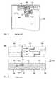
- FIG. 1shows an example of a dielectric antenna, or an antenna based on such a chip component.
- the structureis a dual antenna; it includes two antenna components with a ceramic substrate on the circuit board PCB of a radio device and the partial antennas corresponding to them.
- the antenna structurehas a lower and an upper resonance, and it has correspondingly two bands: the lower operating band is implemented by the first antenna component 110 and the upper operating band by the second antenna component 120 .
- On the surface of the substrate of the first antenna componentsthere are two antenna elements with same size, between which elements remains a relatively narrow slot on the top surface of the substrate.
- the feed conductor of the partial antenna in questionleads to one element, and the other element is a parasitic element connected to the ground GND and getting its feed electromagnetically over said slot.
- the second antenna component 120On the surface of the substrate of the second antenna component 120 there is in this case one antenna element, which is connected both to the feed conductor of the partial antenna in question and to the ground. There is no ground plane below the antenna components, and the ground plane beside them is at a certain distance from them to match the partial antennas.
- the partial antennashave a shared feed conductor 131 connected to the antenna port AP of the radio apparatus, which conductor branches to feed conductors leading to the antenna components. If these feed conductor branches were connected directly to the radiating elements, the partial antennas would adversely affect each other via their shared feed so that the tuning of one would change the tuning of the other. Furthermore, the upper resonance would easily become weak or it would not excite at all. For this reason the structure requires matching components. In the example of FIG. 1 , in series with the feed conductor of the first antenna component 110 there are a coil L 1 and a capacitor C 1 .
- the natural frequency of the resonance circuit constituted by theseis the same as the centre frequency of the lower operating band.
- a capacitor C 2In series with the feed conductor of the second antenna component 120 there is a capacitor C 2 , and between its end on the side of the antenna component and the ground plane GND there is a coil L 2 .
- the boundary frequency of the high-pass filter constituted by the capacitor C 2 and the coil L 2is somewhat below the upper operating band.
- a disadvantage of the solution according to FIG. 1is the space required by the matching components on the circuit board and additional costs in production incurred by them. It is conceivable that the required matching is made without discrete components with conductor patterns on the surface of the circuit board, but in any case this kind of patterns would require a relatively large area on the circuit board.
- FIG. 2shows another example of a known dual antenna.
- the partial antennashave a shared substrate 240 , which together with the radiating elements constitutes an antenna component 200 . Only this antenna component seen from above and sideways is presented in FIG. 2 .
- the lower operating band of the whole antenna structureis implemented by the first partial antenna and the upper operating band by the second partial antenna.
- the substrate 240is divided to the substrate of the first partial antenna, or the first partial substrate 241 , and the substrate of the second partial antenna, or the second partial substrate 242 .
- the partial substratesare here separated from each other by three holes HL 1 , HL 2 , HL 3 extending vertically through the substrate and by two grooves CH 1 , CH 2 .
- the first groove CH 1is at the holes downwards from the top surface of the substrate and the second groove CH 2 is at the holes upwards from the bottom surface of the substrate.
- four relatively narrow necksremain to connect the partial substrates. In this way the electrical isolation and the matching possibilities of the partial antennas are improved.
- the first partial antennacomprises the first 211 and second 212 radiating element.
- the first radiating element 211covers one portion of the top surface of the partial substrate 241 and extends through said holes a bit on the side of the bottom surface of the substrate to constitute the contact pad 217 .
- the first radiating elementis connected to the feed conductor through that contact pad, which then is the shared feed point of the partial antennas.
- the second antenna element 212covers another portion of the top surface of the partial substrate 241 and extends through its head surface a bit on the side of the bottom surface of the substrate to constitute the contact pads 219 .
- the second radiating elementis connected to the signal ground through these contact pads.
- the second radiating elementis then parasitic; it gets its feed electromagnetically over the narrow slot between the elements.
- the second partial antennacomprises the third radiating element 221 . This element covers at least partly the top surface and the outer head surface of the second partial substrate 242 .
- the second partial antennagets its feed galvanically through the first radiating element 211 and an intermediate conductor 232 .
- the intermediate conductoris located in this example on one side surface of the substrate 240 , which is coated by conductor so that the opposing ends of the first and third radiating element become coupled to each other. In this case the intermediate conductor 232 has to go round the end of the first groove CH 1 thus forming a U-shaped bend.
- the main direction of the radiating elements of the first partial antenna and the main direction of the radiating element of the second partial antennaare opposing seen from the shared feed point. This improves from its part the electrical isolation and matching of the partial antennas.
- the present inventionaddresses the foregoing needs by disclosing apparatus and methods for a multiband antenna, including an antenna component.
- a multiband antennacomprises a dual band antenna which comprises a substrate comprising a width and a length, the substrate further comprising: a first antenna operating at a first operating band; and a second antenna operating at a second operating band, the second operating band substantially differing from the first operating band.
- the first antenna and the second antennashare a feed point and a feed conductor, and at least one of the first or second antennas comprises a first radiator and a second radiator, and at least one of the antennas comprises a third radiator; and the first radiator comprises the feed point and the second radiator comprises a first end and a second end, the second end coupled to a ground and disposed farther from the first radiator than the first end.
- the lengthis larger than the width
- the first radiatorfurther comprises at least one short circuit point and at least one short circuit conductor associated therewith, the distance between the at least one short circuit point and the feed point being no larger than the width
- the number of the at least one short circuit pointsis one, the short-circuit conductor located on a back surface of the substrate opposite a front surface comprising the feed conductor.
- the number of the at least one short circuit pointsis one, the short-circuit conductor located on the same surface as the feed conductor.
- the number of the at least one short circuit pointsis two, and wherein a first short-circuit conductor comprising a first short-circuit point is located on the same surface of the substrate as the feed conductor, and a second short-circuit conductor comprising a second short-circuit point is located on the same surface of the substrate as the feed conductor and on the opposite side of the feed conductor as the first short-circuit conductor.
- the number of the at least one short circuit pointsis two, and a first short-circuit conductor comprising a first short-circuit point is located on the same surface of the substrate as the feed conductor and a second short-circuit conductor comprising a second short-circuit point is located on a surface of the substrate opposite the feed conductor and the first short-circuit conductor.
- the first and second radiatorsare separated from each other by a narrow slot.
- the first radiatormay wholly be located on an upper surface of the substrate.
- at least one of the first or second radiatorsextends from an upper surface of the substrate to a front or a back surface.
- a method of operating a dual band antennacomprises one partial antenna associated with a lower operating band of the antenna and a second partial antenna associated with an upper operating band, the partial antennas having a shared substrate, a shared feed point, and the method comprises: operating at least one of the partial antennas as two radiators; operating the first radiator and the radiator of the other partial antenna, which joins the shared feed point, as a unitary common element on the substrate surface; and short-circuiting the common element to ground from at least one point proximate to the feed point.
- one of the lower and upper bandscomprises a global positioning system (GPS) band
- one of the lower and upper bandscomprises a wireless local area network (WLAN) band.
- GPSglobal positioning system
- WLANwireless local area network
- an antenna componentfor use in a radio frequency device.
- the componentcomprises: a first partial antenna implementing a lower operating band; and a second partial antenna implementing an upper operating band, the first and second partial antennas comprising a shared dielectric substrate.
- the first and second partial antennascomprise a shared feed point and a shared feed conductor disposed on a front surface of the substrate.
- a part of the antenna component in a first direction relative to a cross-section of the substrate which leads through the feed pointis associated with the first partial antenna, and a part of the antenna component in the opposite direction is associated with the second partial antenna.
- At least one of the first or second partial antennascomprises two radiators, the first of which joins galvanically at the feed point, and the second of which is connected to a ground plane from an outer end; and wherein the first radiator and a radiator of the other partial antenna joining the shared feed point form a unitary common element on the upper surface of the substrate.
- the unitary common elementis connected to the ground plane from at least one short-circuit point proximate to the feed point.
- At least one short-circuit pointcomprises one point of the unitary common element, and further comprising a short-circuit conductor in communication with the one point and located on a back surface of the substrate opposite the feed conductor.
- the componentfurther comprises a short-circuit conductor starting from the at least one point and located on the front surface of the substrate.
- the at least one short-circuit point of the common elementcomprises first and second points
- the componentfurther comprises a first short-circuit conductor starting from the first short-circuit point and located at least partly on the front surface of the substrate on one side of the feed conductor, and a second short-circuit conductor starting from the second short-circuit point located at least partly on the front surface of the substrate on the other side of the feed conductor than the first short-circuit conductor.
- the componentfurther comprises a reactive matching component connected between an antenna feed conductor and a signal ground.
- the shared substratecomprises a ceramic material.
- a dual antenna of a radio devicecomprises: a first partial antenna to implement a lower operating band of the antenna; and a second partial antenna to implement an upper operating band, the first and second partial antennas having a shared dielectric substrate which forms an integrated antenna component together with antenna radiators, the partial antennas having a shared feed point and a shared feed conductor on the front surface of the substrate.
- a part of the antenna component in one direction from a substrate cross section which leads through the feed pointbelongs to the first partial antenna, and a part of the antenna component in the opposite direction belongs to the second partial antenna.
- At least one partial antennacomprises two radiators, the first of which joins the feed point and the second of which is adapted for connection to a ground plane, and the first radiator and a radiator of the other partial antenna joining the shared feed point form a unitary common element on the upper surface of the substrate, which element is configured for connection to the ground plane from at least one short-circuit point proximate to the feed point.
- the at least one the short-circuit pointcomprises a single point
- the antennafurther comprises a short-circuit conductor communicating with the single point is located on back surface of the substrate substantially opposite the feed conductor.
- the at least one short-circuit pointcomprises a single point, and a short-circuit conductor communicating with the single point is located in majority on the front surface of the substrate on at least one side of the feed conductor.
- the at least one pointcomprises first and second points, and a first short-circuit conductor communicating with the first short-circuit point is located substantially on the front surface of the substrate on one side of the feed conductor, and a second short-circuit conductor communicating with the second short-circuit point is located substantially on the front surface of the substrate on the other side of the feed conductor.
- an integrated dual-band antennacomprises: at least first and second partial antennas disposed on a common substrate; and a shared feed point adapted for matching in both of the operating bands, the antenna comprising at least one short-circuit point disposed proximate to a feed point to permit the matching.
- the antennais adapted for the matching in either of the two bands without significantly degrading the matching in the other of the two bands.
- isolation between the first and second partial antennasis maintained despite the common substrate.
- FIG. 1shows an example of a prior art dielectric dual antenna.
- FIG. 2shows another example of a prior art dielectric dual antenna.
- FIG. 3shows an exemplary embodiment of a dielectric dual antenna according to the invention.
- FIG. 4shows a second exemplary embodiment of a dielectric dual antenna according to the invention.
- FIG. 5shows a third exemplary embodiment of a dielectric dual antenna according to the invention.
- FIG. 6shows a fourth exemplary embodiment of a dielectric dual antenna according to the invention.
- FIG. 7shows a fifth exemplary embodiment of a dielectric dual antenna according to the invention.
- FIG. 8shows a sixth exemplary embodiment of a dielectric dual antenna according to the invention.
- FIG. 9shows a seventh exemplary embodiment of a dielectric dual antenna according to the invention.
- FIG. 10shows an eighth exemplary embodiment of a dielectric dual antenna according to the invention.
- FIG. 11shows another embodiment of a dielectric dual antenna according to the invention as mounted.
- FIG. 12shows exemplary band characteristics of one embodiment of an antenna according to the invention.
- wirelessrefers without limitation to any wireless signal, data, communication, or other interface or radiating component including without limitation Wi-Fi, Bluetooth, 3G (3GPP/3GPPS), HSDPA/HSUPA, TDMA, CDMA (e.g., IS-95A, WCDMA, etc.), FHSS, DSSS, GSM, UMTS, PAN/802.15, WiMAX (802.16), 802.20, narrowband/FDMA, OFDM, PCS/DCS, analog cellular, CDPD, satellite systems, millimeter wave, or microwave systems.
- the dielectric antennais a dual antenna, one partial antenna of which is implemented the lower operating band of the antenna and the other partial antenna the upper operating band.
- the partial antennashave a shared substrate, which together with the radiators constitutes an integrated antenna component.
- the partial antennasalso have a shared feed point, the part of the antenna component to one direction from the plane, which leads through the feed point and is perpendicular to the upper surface of the substrate, belonging to one partial antenna and the part of the antenna component to the opposite direction belonging to the other partial antenna.
- At least one of the partial antennascomprises two radiators, the first one of which joins the feed point and the second one is connected to the ground from its outer end as viewed from the first radiator.
- This first radiator and the radiator of the other partial antenna, which joins the shared feed pointform a unitary common element on the substrate surface. This common element is short-circuited to the ground from at least one point relatively near to the feed point.
- One salient advantage of the inventionis that an integrated dual antenna provided with a shared feed point can be matched relatively easily in its both operating bands. This is due to the fact that the short-circuits near to the feed point itself improve the total matching of the antenna, and further enable an additional improvement of the matching by extra component in either operating band without degrading the matching in the other operating band at the same time. Relating to the matching improvement, the isolation between the partial antennas is maintained, although they have the shared substrate.
- Another advantage of the inventionis high antenna efficiency in spite of the small size of the antenna.
- FIGS. 1 and 2were already described in connection with the description of prior art.
- FIG. 3shows an example of a dielectric dual antenna according to the invention.
- the integrated antenna component 300comprises a substrate 340 shared between the partial antennas and the radiating elements of the antenna as conductor coatings of the substrate.
- the substrate 340is here an elongated ceramic piece substantially shaped like a right-angled prism without any holes or grooves which would divide the piece.
- the number of the radiating elementsis three in this example: the common element 330 according to the invention, the first end element 312 and the second end element 322 .
- the feed conductor FC and the feed point FPare shared between the partial antennas.
- the feed pointfunctionally divides the antenna component into two parts so that starting from the substrate cross section which leads through the feed point, the part towards the first end element 312 belongs to the first partial antenna and the part of the antenna component to the opposite direction, or towards the second end element 322 , belongs to the second partial antenna.
- the common element 330functionally comprises two parts: the first radiator 311 of the first partial antenna and the first radiator 321 of the second partial antenna.
- the first end element 312is the second radiator of the first partial antenna and the second end element 322 is the second radiator of the second partial antenna. More briefly, the first radiator of the first partial antenna is only called the first radiator, the second radiator of the first partial antenna only the second radiator, the first radiator of the second partial antenna only the third radiator and the second radiator of the second partial antenna only the fourth radiator. Between the first 311 and second 312 radiator there is only a narrow slot travelling across the upper surface of the substrate, partly in its longitudinal direction, the second radiator receiving its feed electromagnetically over the slot. Seen from the feed point FP, the outer end of the first radiator 311 continues from the upper surface of the substrate, where the common element 330 mostly is located, to the front surface of the substrate.
- the end of the second radiator 312 nearest to the feed point FPcontinues from the upper surface of the substrate to the back surface of the substrate.
- the second radiatorcovers also the first head surface of the substrate 340 and extends a little to its lower surface, where it connects to the signal ground, or ground plane GND, when the antenna component has been mounted.
- a narrow slot travelling across the upper surface of the substrateis between the third 321 and fourth 322 radiator, the fourth radiator receiving its feed electromagnetically over this slot.
- the fourth radiatorcovers also the second head surface of the substrate and extends a little to its lower surface, where it connects to the ground plane, when the antenna component has been mounted.
- the common element 330is also connected to the ground plane GND from the short-circuit point SP, which is located opposite the feed point FP on the other edge of the upper surface of the substrate.
- the distance between the short-circuit and feed pointsis about the width of the substrate, which is relatively small compared with the length of the substrate.
- the ground connection of the common elementis implemented by the short-circuit conductor SC, which is located on the back surface of the substrate opposite the feed conductor FC viewed in the transverse direction of the substrate and extends a little to its lower surface for constituting a contact surface.
- the total matching of the antennacan be improved by means of such a short-circuit relatively close to the feed point, especially together with a matching component connected to the feed conductor.
- the lower surface of the substratemeans its surface, coating of which is substantially only relatively small contact surfaces for mounting the antenna component
- the front surfacemeans the surface, on which the feed conductor FC is located.
- the use position of the antenna componentcan naturally be any.
- the first headmeans the head on the side of the first end element, and ‘the second head’ means naturally the opposite head in respect of the first head.
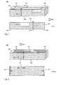
- FIG. 4shows a second example of the dielectric dual antenna according to the invention.
- the antenna component 400is seen from the front side as a perspective depiction and in the second partial figure from below.
- the antenna componentcomprises a substrate 440 shared between the partial antennas and the radiating elements of the antenna as conductor coatings of the substrate.
- the substrate 440is also in this example an elongated ceramic piece shaped substantially like a right-angled prism, and on its surface there are the common element 430 , the first end element 412 and the second end element 422 as in FIG. 3 .
- the substantial difference to the structure shown in FIG. 3is that there are now two short-circuit conductors of the common element instead of one, and these both conductors are located on the front surface of the substrate.
- the antenna impedances on the lower and upper operating bandcan be set so that a further improvement of the matching by an extra component in either operating band does not degrade the matching in the other operating band at the same time.
- FIG. 5shows a third example of the dielectric dual antenna according to the invention.
- the antenna component 500is seen from the front side as a perspective depiction.
- the antenna componentcomprises a substrate 540 shared between the partial antennas and the radiating elements of the antenna as conductor coatings of the substrate.
- On the surface of the substratethere are the common element 530 and the first end element 512 as in FIGS. 3 and 4 .
- the difference to the structure shown in those figuresis that the second partial antenna now comprises only one radiator 520 which, together with the first radiator like the one in the foregoing examples, constitutes the common element 530 .
- the radiator 520 of the second partial antennacovers the upper surface of the substrate 540 on the side of the second head and can extend to the second head surface, but not there from onwards to the ground plane, being then open at its outer end.
- the common elementhas in this example one short-circuit conductor SC, which is located on the front surface of the substrate next to the feed conductor FC on the side of the second head.
- the second partial antennacan be considered to be of PIFA type, if the antenna ground plane is extended below the third radiator 520 .
- the same short-circuitalso effects on the matching of the first partial antenna at the same time.
- FIG. 6shows a fourth example of the dielectric dual antenna according to the invention.
- the second partial antennacomprises only one radiator 620 , which is not grounded from its outer end, as in the example of FIG. 5 .
- the difference to the structure shown in FIG. 5is that the third radiator 620 now is meander-shaped.
- the short-circuit conductor SC of the common element 630is located on the side of the first head in respect of the feed conductor FC.
- FIG. 7shows a fifth example of the dielectric dual antenna according to the invention.
- the antenna component 700is seen from the back side as a perspective depiction.
- the common element 730 belonging to itcomprises two short-circuit points and conductors, as in FIG. 4 , but now the second short-circuit conductor SC 2 is located on the back surface of the substrate 740 , the first short-circuit conductor being located on the front surface of the substrate next to the feed conductor.
- An additional difference to the structure shown in FIG. 4is that now the second radiator 712 of the first partial antenna is mostly located on the back surface of the substrate.
- first head surface of the substrateIt covers also the first head surface of the substrate so that the slot between the first 711 and second 712 radiator travels across the upper surface of the substrate close to the first head and continues then along the upper edge of the back surface towards the second head.
- the first radiator 711is wholly located on the upper surface of the substrate.
- FIG. 8shows a sixth example of the dielectric dual antenna according to the invention.
- the antenna component 800is seen from the back side as a perspective depiction and in the second partial figure from below.
- the common element 830has a single short-circuit conductor and this conductor is located on the front surface of the substrate 840 next to the feed conductor.
- the common elementcontinues from the upper surface of the substrate to the back surface on the area, which extends in the longitudinal direction from the point opposite to the feed point FP near to the second head.
- the first radiator 821 of the second partial antennaextends also to the back surface.
- a part of the second radiator 822 of the second partial antennais located on the back surface, the large part of it being located on the upper surface and the second head surface.
- the first 811 and second 812 radiator of the first partial antennaare located so that the slot between them on the upper surface of the substrate starts on the side of the front surface close to the feed point FP, travels longitudinally in the middle of the upper surface to a point relatively close to the first head and turns after that sideways towards the back surface.
- the second radiator 812can extend from the upper surface also on the side of the front surface.
- FIG. 9shows a seventh example of the dielectric dual antenna according to the invention.
- the antenna component 900is seen from the front side as a perspective depiction.
- the difference to the structure shown in FIG. 4is that now the slot 925 between the radiators 921 , 922 of the second partial antenna is located on the second head surface instead of the upper surface.
- the slot between the radiators 911 , 912 of the first partial antennastarts here on the side of the front surface close to the first head and travels diagonally across the upper surface to the side of the back surface close to the second head.
- FIG. 10shows an eighth example of the dielectric dual antenna according to the invention.
- the substrate of the antenna component A 00is in this example a rounded plate so that its front surface, back surface and head surfaces all have roughly the same size.
- the slot A 15 between the radiators A 11 , A 12 of the first partial antenna and the slot A 25 between the radiators A 21 , A 22 of the second partial antennamake boundaries of the common element.
- the former slotmakes a curved line across the upper surface of the substrate from the side of the first head surface to the side of the back surface
- the latter slot A 25travels across the upper surface of the substrate from the side of the front surface to the border area of the back surface and the second head surface.
- One radiator of both partial antennasare intended to be connected to the ground from their outer edge, seen from the common element A 30 .
- FIG. 11shows an example of a dielectric dual antenna according to the invention as mounted.
- a part of the circuit board PCB of a radio deviceis seen in the figure, the upper surface of the board largely being of conductive ground plane.
- the antenna component B 00has been fastened from its lower surface to the circuit board close to its one end.
- the feed conductor FC on the front surface of the antenna componentcontinues on the circuit board as a conductor FC′. Between this conductor FC′ and the signal ground there is connected the reactive matching component B 50 of the antenna.
- the antenna impedances in the operating bandsnaturally depend on several factors such as the size of the circuit board, the place of the antenna component on the circuit board, the shape of the ground plane and the other conductive parts of the device.
- the matchingscan succeed also without a discrete matching component.
- the edge of the ground plane GNDis in the example of FIG. 11 at a certain distance from the antenna component B 00 in its transverse direction. That distance is a variable in the antenna design.
- the antennacan be designed also so that the ground plane extends at least partially below the antenna component.
- FIG. 12shows an example of the band characteristics of an antenna according to the invention.
- the curveshows the fluctuation of the reflection coefficient S 11 as a function of frequency.
- the lower reflection coefficientthe better the antenna has been matched and the better it functions as a radiator and a receiver of radiation.
- the antennahas been designed so that its lower operating band covers the narrow range at the frequency 1575 MHz used by the GPS (Global Positioning System).
- the upper operating bandagain well covers the frequency range used by the WLAN system (Wireless Local Area Network), which range is 2400-2484 MHz in the EU countries and the USA.
- the antennacould be designed so that the lower operating band would cover e.g. the frequency range used by the GSM900 system and the upper operating band cover e.g.
- the efficiency of the antenna according to the inventionis good especially in the upper operating band considering the small size (for example 15 mm ⁇ 3 mm ⁇ 4 mm) of the antenna. In the free space the efficiency is typically about 50% in the lower operating band and about 60-70% in the upper operating band.
- An antenna according to the inventioncan naturally differ in its details from the ones described.
- the shapes of the radiating elementscan vary also in other ways than what appears from the examples.
- the shape of the substratecan vary.
- the places of the short-circuits of the common elementcan vary regardless of the number and shapes of the radiators.
- the substratecan be instead of ceramic, also of other dielectric material, as pure silicon.
- the antennais manufactured by growing a metal layer on the surface of the silicon and removing a portion of it with a technology used in manufacturing of semiconductor components.
- the inventive ideacan be applied in different ways within the limitations set by the independent claim 1 .
Landscapes
- Engineering & Computer Science (AREA)
- Computer Networks & Wireless Communication (AREA)
- Waveguide Aerials (AREA)
- Details Of Aerials (AREA)
- Variable-Direction Aerials And Aerial Arrays (AREA)
Abstract
Description
Claims (41)
Applications Claiming Priority (2)
| Application Number | Priority Date | Filing Date | Title |
|---|---|---|---|
| FI20075687 | 2007-09-28 | ||
| FI20075687AFI124129B (en) | 2007-09-28 | 2007-09-28 | dual Antenna |
Publications (2)
| Publication Number | Publication Date |
|---|---|
| US20080204328A1 US20080204328A1 (en) | 2008-08-28 |
| US8179322B2true US8179322B2 (en) | 2012-05-15 |
Family
ID=38573019
Family Applications (1)
| Application Number | Title | Priority Date | Filing Date |
|---|---|---|---|
| US12/009,009Active2030-05-16US8179322B2 (en) | 2007-09-28 | 2008-01-15 | Dual antenna apparatus and methods |
Country Status (5)
| Country | Link |
|---|---|
| US (1) | US8179322B2 (en) |
| EP (1) | EP1933417A1 (en) |
| KR (1) | KR100995540B1 (en) |
| CN (1) | CN101237079B (en) |
| FI (1) | FI124129B (en) |
Cited By (40)
| Publication number | Priority date | Publication date | Assignee | Title |
|---|---|---|---|---|
| US20110122043A1 (en)* | 2009-11-24 | 2011-05-26 | Digi International Inc. | Wideband antenna for printed circuit boards |
| US8466756B2 (en) | 2007-04-19 | 2013-06-18 | Pulse Finland Oy | Methods and apparatus for matching an antenna |
| US8473017B2 (en) | 2005-10-14 | 2013-06-25 | Pulse Finland Oy | Adjustable antenna and methods |
| US8564485B2 (en) | 2005-07-25 | 2013-10-22 | Pulse Finland Oy | Adjustable multiband antenna and methods |
| US20130335295A1 (en)* | 2012-06-13 | 2013-12-19 | Wistron Corp. | Antenna module |
| US8618990B2 (en) | 2011-04-13 | 2013-12-31 | Pulse Finland Oy | Wideband antenna and methods |
| US8629813B2 (en) | 2007-08-30 | 2014-01-14 | Pusle Finland Oy | Adjustable multi-band antenna and methods |
| US8648752B2 (en) | 2011-02-11 | 2014-02-11 | Pulse Finland Oy | Chassis-excited antenna apparatus and methods |
| US8786499B2 (en) | 2005-10-03 | 2014-07-22 | Pulse Finland Oy | Multiband antenna system and methods |
| US20140253393A1 (en)* | 2013-03-11 | 2014-09-11 | Pulse Finland Oy | Coupled antenna structure and methods |
| US8847833B2 (en) | 2009-12-29 | 2014-09-30 | Pulse Finland Oy | Loop resonator apparatus and methods for enhanced field control |
| US8866689B2 (en) | 2011-07-07 | 2014-10-21 | Pulse Finland Oy | Multi-band antenna and methods for long term evolution wireless system |
| US8988296B2 (en) | 2012-04-04 | 2015-03-24 | Pulse Finland Oy | Compact polarized antenna and methods |
| US9123990B2 (en) | 2011-10-07 | 2015-09-01 | Pulse Finland Oy | Multi-feed antenna apparatus and methods |
| US9203154B2 (en) | 2011-01-25 | 2015-12-01 | Pulse Finland Oy | Multi-resonance antenna, antenna module, radio device and methods |
| US20160006117A1 (en)* | 2014-07-03 | 2016-01-07 | Hitachi Metals, Ltd. | Antenna Device |
| US9246210B2 (en) | 2010-02-18 | 2016-01-26 | Pulse Finland Oy | Antenna with cover radiator and methods |
| US9350081B2 (en) | 2014-01-14 | 2016-05-24 | Pulse Finland Oy | Switchable multi-radiator high band antenna apparatus |
| US9406998B2 (en) | 2010-04-21 | 2016-08-02 | Pulse Finland Oy | Distributed multiband antenna and methods |
| US9450291B2 (en) | 2011-07-25 | 2016-09-20 | Pulse Finland Oy | Multiband slot loop antenna apparatus and methods |
| US9461371B2 (en) | 2009-11-27 | 2016-10-04 | Pulse Finland Oy | MIMO antenna and methods |
| US9484619B2 (en) | 2011-12-21 | 2016-11-01 | Pulse Finland Oy | Switchable diversity antenna apparatus and methods |
| US9531058B2 (en) | 2011-12-20 | 2016-12-27 | Pulse Finland Oy | Loosely-coupled radio antenna apparatus and methods |
| US9564683B2 (en) | 2013-05-02 | 2017-02-07 | Samsung Electronics Co., Ltd. | Multi band antenna device and wireless communication device including multi band antenna |
| US9590308B2 (en) | 2013-12-03 | 2017-03-07 | Pulse Electronics, Inc. | Reduced surface area antenna apparatus and mobile communications devices incorporating the same |
| US9634383B2 (en) | 2013-06-26 | 2017-04-25 | Pulse Finland Oy | Galvanically separated non-interacting antenna sector apparatus and methods |
| US9647338B2 (en) | 2013-03-11 | 2017-05-09 | Pulse Finland Oy | Coupled antenna structure and methods |
| US9673507B2 (en) | 2011-02-11 | 2017-06-06 | Pulse Finland Oy | Chassis-excited antenna apparatus and methods |
| US9680212B2 (en) | 2013-11-20 | 2017-06-13 | Pulse Finland Oy | Capacitive grounding methods and apparatus for mobile devices |
| US20170214143A1 (en)* | 2014-08-07 | 2017-07-27 | Byd Company Limited | Antenna radiator, antenna and mobile terminal |
| US9722308B2 (en) | 2014-08-28 | 2017-08-01 | Pulse Finland Oy | Low passive intermodulation distributed antenna system for multiple-input multiple-output systems and methods of use |
| US9761951B2 (en) | 2009-11-03 | 2017-09-12 | Pulse Finland Oy | Adjustable antenna apparatus and methods |
| US9906260B2 (en) | 2015-07-30 | 2018-02-27 | Pulse Finland Oy | Sensor-based closed loop antenna swapping apparatus and methods |
| US9948002B2 (en) | 2014-08-26 | 2018-04-17 | Pulse Finland Oy | Antenna apparatus with an integrated proximity sensor and methods |
| US9973228B2 (en) | 2014-08-26 | 2018-05-15 | Pulse Finland Oy | Antenna apparatus with an integrated proximity sensor and methods |
| US9979078B2 (en) | 2012-10-25 | 2018-05-22 | Pulse Finland Oy | Modular cell antenna apparatus and methods |
| US10069209B2 (en) | 2012-11-06 | 2018-09-04 | Pulse Finland Oy | Capacitively coupled antenna apparatus and methods |
| EP4054001A1 (en)* | 2021-02-26 | 2022-09-07 | Tyco Electronics AMP Korea Co., Ltd. | Antenna module and antenna device having the same |
| US11664601B2 (en) | 2020-09-25 | 2023-05-30 | Apple Inc. | Electronic devices with coexisting antennas |
| US12132251B2 (en) | 2020-05-20 | 2024-10-29 | Vivo Mobile Communication Co., Ltd. | Electronic device |
Families Citing this family (20)
| Publication number | Priority date | Publication date | Assignee | Title |
|---|---|---|---|---|
| WO2006000650A1 (en) | 2004-06-28 | 2006-01-05 | Pulse Finland Oy | Antenna component |
| FI119535B (en)* | 2005-10-03 | 2008-12-15 | Pulse Finland Oy | Multiple-band antenna |
| FI118872B (en) | 2005-10-10 | 2008-04-15 | Pulse Finland Oy | Built-in antenna |
| US7423605B2 (en)* | 2006-01-13 | 2008-09-09 | Research In Motion Limited | Mobile wireless communications device including an electrically conductive director element and related methods |
| US10211538B2 (en) | 2006-12-28 | 2019-02-19 | Pulse Finland Oy | Directional antenna apparatus and methods |
| KR100901177B1 (en)* | 2008-10-14 | 2009-06-04 | (주)파트론 | Built-in dual feed antenna |
| FI20095763L (en)* | 2009-07-06 | 2011-01-07 | Pulse Finland Oy | Dielectric multiband antenna |
| US20110037655A1 (en)* | 2009-08-17 | 2011-02-17 | Yueh-Lin Tsai | Dielectric-loaded and coupled planar antenna |
| CN102195122B (en)* | 2010-03-12 | 2014-01-22 | 宏碁股份有限公司 | Thin mobile communication device |
| TWI455403B (en)* | 2010-04-27 | 2014-10-01 | Ind Tech Res Inst | Mobile communication device |
| CN102244524A (en)* | 2010-05-10 | 2011-11-16 | 财团法人工业技术研究院 | Mobile communication device |
| JP5485807B2 (en)* | 2010-06-16 | 2014-05-07 | 日精株式会社 | Substrate antenna |
| CN102760948A (en)* | 2012-07-12 | 2012-10-31 | Tdk大连电子有限公司 | Ultrathin small dual-frequency ceramic antenna |
| TWI527307B (en)* | 2013-05-29 | 2016-03-21 | 智易科技股份有限公司 | Antanna structure |
| US9640869B2 (en)* | 2015-07-01 | 2017-05-02 | WiseWear Corporation | Coplanar antenna |
| CN115939736A (en)* | 2017-07-06 | 2023-04-07 | 伊格尼恩有限公司 | Modular multi-stage antenna system and assembly for wireless communication |
| US10615492B2 (en)* | 2018-07-18 | 2020-04-07 | Nxp B.V. | Multi-band, shark fin antenna for V2X communications |
| MX2019005691A (en) | 2018-07-31 | 2020-08-31 | Flex Ltd | Antennas and devices, systems, and methods including the same. |
| CN110797634B (en)* | 2018-08-03 | 2022-04-05 | 荣耀终端有限公司 | Antenna structure and electronic equipment |
| WO2024050994A1 (en)* | 2022-09-08 | 2024-03-14 | 昆山睿翔讯通通信技术有限公司 | Mobile terminal antenna and mobile terminal |
Citations (82)
| Publication number | Priority date | Publication date | Assignee | Title |
|---|---|---|---|---|
| US5043738A (en)* | 1990-03-15 | 1991-08-27 | Hughes Aircraft Company | Plural frequency patch antenna assembly |
| US5389937A (en)* | 1984-05-01 | 1995-02-14 | The United States Of America As Represented By The Secretary Of The Navy | Wedge feed system for wideband operation of microstrip antennas |
| US5557292A (en) | 1994-06-22 | 1996-09-17 | Space Systems/Loral, Inc. | Multiple band folding antenna |
| EP0766341A1 (en) | 1995-09-29 | 1997-04-02 | Murata Manufacturing Co., Ltd. | Surface mounting antenna and communication apparatus using the same antenna |
| EP0831547A2 (en) | 1996-09-20 | 1998-03-25 | Murata Manufacturing Co., Ltd. | Microstrip antenna |
| EP0942488A2 (en) | 1998-02-24 | 1999-09-15 | Murata Manufacturing Co., Ltd. | Antenna device and radio device comprising the same |
| EP1003240A2 (en) | 1998-11-17 | 2000-05-24 | Murata Manufacturing Co., Ltd. | Surface mount antenna and communication apparatus using the same |
| WO2000036700A1 (en) | 1998-12-16 | 2000-06-22 | Telefonaktiebolaget Lm Ericsson (Publ) | Printed multi-band patch antenna |
| US6133879A (en) | 1997-12-11 | 2000-10-17 | Alcatel | Multifrequency microstrip antenna and a device including said antenna |
| US6177908B1 (en) | 1998-04-28 | 2001-01-23 | Murata Manufacturing Co., Ltd. | Surface-mounting type antenna, antenna device, and communication device including the antenna device |
| WO2001033665A1 (en) | 1999-11-04 | 2001-05-10 | Rangestar Wireless, Inc. | Single or dual band parasitic antenna assembly |
| JP2001217631A (en) | 2000-02-04 | 2001-08-10 | Murata Mfg Co Ltd | Surface-mounted antenna and its adjusting method, and communication device equipped with surface-mounted type antenna |
| US6316975B1 (en) | 1996-05-13 | 2001-11-13 | Micron Technology, Inc. | Radio frequency data communications device |
| EP1162688A1 (en) | 1999-09-30 | 2001-12-12 | Murata Manufacturing Co., Ltd. | Surface-mount antenna and communication device with surface-mount antenna |
| US20010050654A1 (en)* | 1998-03-17 | 2001-12-13 | Killen William D. | Printed circuit board-configured dipole array having matched impedance-coupled microstrip feed and parasitic elements for reducing sidelobes |
| WO2002011236A1 (en) | 2000-08-01 | 2002-02-07 | Sagem Sa | Planar radiating surface antenna and portable telephone comprising same |
| US6407171B1 (en)* | 1999-12-20 | 2002-06-18 | Exxon Chemical Patents Inc. | Blends of polyethylene and polypropylene |
| WO2002078123A1 (en) | 2001-03-23 | 2002-10-03 | Telefonaktiebolaget L M Ericsson (Publ) | A built-in, multi band, multi antenna system |
| US20020145569A1 (en) | 2001-04-10 | 2002-10-10 | Murata Manufacturing Co., Ltd. | Antenna apparatus |
| US6473056B2 (en) | 2000-06-12 | 2002-10-29 | Filtronic Lk Oy | Multiband antenna |
| US20020163470A1 (en) | 2001-05-02 | 2002-11-07 | Murata Manufacturing Co., Ltd. | Antenna device and radio communication equipment including the same |
| US20020196192A1 (en) | 2001-06-20 | 2002-12-26 | Murata Manufacturing Co., Ltd. | Surface mount type antenna and radio transmitter and receiver using the same |
| US20030006936A1 (en) | 2001-06-15 | 2003-01-09 | Hitachi Metals, Ltd. | Surface-mounted antenna and communications apparatus comprising same |
| US20030020659A1 (en) | 2001-07-25 | 2003-01-30 | Murata Manufacturing Co., Ltd. | Surface mount antenna, method of manufacturing the surface mount antenna, and radio communication apparatus equipped with the surface mount antenna |
| EP1294049A1 (en) | 2001-09-14 | 2003-03-19 | Nokia Corporation | Internal multi-band antenna with improved radiation efficiency |
| DE10150149A1 (en) | 2001-10-11 | 2003-04-17 | Receptec Gmbh | Antenna module for automobile mobile radio antenna has antenna element spaced above conductive base plate and coupled to latter via short-circuit path |
| US6606016B2 (en) | 2000-03-10 | 2003-08-12 | Murata Manufacturing Co., Ltd. | Surface acoustic wave device using two parallel connected filters with different passbands |
| US6614400B2 (en) | 2000-08-07 | 2003-09-02 | Telefonaktiebolaget Lm Ericsson (Publ) | Antenna |
| US20030222827A1 (en) | 2002-05-31 | 2003-12-04 | Samsung Electro-Mechanics Co., Ltd. | Broadband chip antenna |
| US20040021607A1 (en) | 2002-07-31 | 2004-02-05 | Alcatel | Multisource antenna, in particular for systems with a reflector |
| EP1414108A2 (en) | 2002-10-23 | 2004-04-28 | Murata Manufacturing Co., Ltd. | Surface mount antenna, antenna device and communication device using the same |
| US20040085244A1 (en) | 2002-11-06 | 2004-05-06 | Kadambi Govind Rangaswamy | Planar inverted-f-antenna (pifa) having a slotted radiating element providing global cellular and gps-bluetooth frequency response |
| US6738022B2 (en) | 2001-04-18 | 2004-05-18 | Filtronic Lk Oy | Method for tuning an antenna and an antenna |
| US20040212493A1 (en) | 2003-02-03 | 2004-10-28 | Stilp Louis A. | RFID reader for a security network |
| WO2004112189A1 (en) | 2003-06-17 | 2004-12-23 | Perlos Ab | A multiband antenna for a portable terminal apparatus |
| US20050024268A1 (en) | 2003-05-09 | 2005-02-03 | Mckinzie William E. | Multiband antenna with parasitically-coupled resonators |
| US6862441B2 (en) | 2003-06-09 | 2005-03-01 | Nokia Corporation | Transmitter filter arrangement for multiband mobile phone |
| US20050057416A1 (en) | 2003-09-01 | 2005-03-17 | Alps Electric Co., Ltd. | Small-size, low-height antenna device capable of easily ensuring predetermined bandwidth |
| US20050078037A1 (en) | 2003-10-09 | 2005-04-14 | Daniel Leclerc | Internal antenna of small volume |
| US20050099347A1 (en) | 2003-11-12 | 2005-05-12 | Kazuhisa Yamaki | Antenna structure and communication device using the same |
| US6903692B2 (en) | 2001-06-01 | 2005-06-07 | Filtronic Lk Oy | Dielectric antenna |
| US20050243001A1 (en) | 2004-04-28 | 2005-11-03 | Akira Miyata | Antenna and radio communication apparatus |
| FI20055621A0 (en) | 2005-11-24 | 2005-11-24 | Lk Products Oy | The multiband antenna component |
| WO2006000650A1 (en) | 2004-06-28 | 2006-01-05 | Pulse Finland Oy | Antenna component |
| WO2006000631A1 (en) | 2004-06-28 | 2006-01-05 | Pulse Finland Oy | Chip antenna |
| US20060017621A1 (en)* | 2003-01-15 | 2006-01-26 | Fdk Corporation | Antenna |
| CN1747234A (en) | 2004-09-06 | 2006-03-15 | 合勤科技股份有限公司 | Dual Band Planar Antenna for Wi-Fi Devices |
| US7057560B2 (en) | 2003-05-07 | 2006-06-06 | Agere Systems Inc. | Dual-band antenna for a wireless local area network device |
| US20060145924A1 (en) | 2004-12-31 | 2006-07-06 | Advanced Connectek Inc. | Dual-band inverted-f antenna with a branch line shorting strip |
| WO2006084951A1 (en) | 2005-02-08 | 2006-08-17 | Pulse Finland Oy | Internal monopole antenna |
| US7142824B2 (en) | 2002-10-07 | 2006-11-28 | Matsushita Electric Industrial Co., Ltd. | Antenna device with a first and second antenna |
| US7148849B2 (en) | 2003-12-23 | 2006-12-12 | Quanta Computer, Inc. | Multi-band antenna |
| US7148851B2 (en) | 2003-08-08 | 2006-12-12 | Hitachi Metals, Ltd. | Antenna device and communications apparatus comprising same |
| WO2007000483A1 (en) | 2005-06-28 | 2007-01-04 | Pulse Finland Oy | Internal multiband antenna |
| US7170464B2 (en) | 2004-09-21 | 2007-01-30 | Industrial Technology Research Institute | Integrated mobile communication antenna |
| US7176838B1 (en) | 2005-08-22 | 2007-02-13 | Motorola, Inc. | Multi-band antenna |
| US7180455B2 (en) | 2004-10-13 | 2007-02-20 | Samsung Electro-Mechanics Co., Ltd. | Broadband internal antenna |
| US7205942B2 (en) | 2005-07-06 | 2007-04-17 | Nokia Corporation | Multi-band antenna arrangement |
| US7218282B2 (en) | 2003-04-28 | 2007-05-15 | Fraunhofer-Gesellschaft Zur Foerderung Der Angewandten Forschung E.V. | Antenna device |
| US20070109202A1 (en) | 2005-11-15 | 2007-05-17 | Scott Vance | Multi-frequency band antenna device for radio communication terminal having wide high-band bandwidth |
| US20070152887A1 (en) | 2004-01-30 | 2007-07-05 | Castany Jordi S | Multi-band monopole antennas for mobile network communications devices |
| US20070152881A1 (en) | 2005-12-29 | 2007-07-05 | Chan Yiu K | Multi-band antenna system |
| US20070159399A1 (en) | 2005-10-03 | 2007-07-12 | Jari Perunka | Multi-band antenna with a common resonant feed structure and methods |
| US7274334B2 (en) | 2005-03-24 | 2007-09-25 | Tdk Corporation | Stacked multi-resonator antenna |
| US7283097B2 (en) | 2002-11-28 | 2007-10-16 | Research In Motion Limited | Multi-band antenna with patch and slot structures |
| US20070241970A1 (en) | 2003-11-12 | 2007-10-18 | Amc Centurion Ab | Antenna Device and Portable Radio Communication Device Comprising Such an Antenna Device |
| US7289064B2 (en) | 2005-08-23 | 2007-10-30 | Intel Corporation | Compact multi-band, multi-port antenna |
| US7292200B2 (en) | 2004-09-23 | 2007-11-06 | Mobile Mark, Inc. | Parasitically coupled folded dipole multi-band antenna |
| US20070268190A1 (en) | 2006-05-17 | 2007-11-22 | Sony Ericsson Mobile Communications Ab | Multi-band antenna for GSM, UMTS, and WiFi applications |
| US20070273606A1 (en) | 2006-05-26 | 2007-11-29 | Hong Kong Applied Science and Technology Research Institude Co., Ltd. | Multi mode antenna system |
| US20070290938A1 (en) | 2006-06-16 | 2007-12-20 | Cingular Wireless Ii, Llc | Multi-band antenna |
| US20080007459A1 (en) | 2004-11-11 | 2008-01-10 | Kimmo Koskiniemi | Antenna component and methods |
| US7330153B2 (en) | 2006-04-10 | 2008-02-12 | Navcom Technology, Inc. | Multi-band inverted-L antenna |
| US7333067B2 (en) | 2004-05-24 | 2008-02-19 | Hon Hai Precision Ind. Co., Ltd. | Multi-band antenna with wide bandwidth |
| US20080042903A1 (en) | 2006-08-15 | 2008-02-21 | Dajun Cheng | Multi-band dielectric resonator antenna |
| US7339528B2 (en) | 2003-12-24 | 2008-03-04 | Nokia Corporation | Antenna for mobile communication terminals |
| US7345634B2 (en) | 2004-08-20 | 2008-03-18 | Kyocera Corporation | Planar inverted “F” antenna and method of tuning same |
| US7352326B2 (en) | 2003-10-31 | 2008-04-01 | Lk Products Oy | Multiband planar antenna |
| US20080088511A1 (en) | 2005-03-16 | 2008-04-17 | Juha Sorvala | Antenna component and methods |
| US7385556B2 (en) | 2006-11-03 | 2008-06-10 | Hon Hai Precision Industry Co., Ltd. | Planar antenna |
| US7423592B2 (en) | 2004-01-30 | 2008-09-09 | Fractus, S.A. | Multi-band monopole antennas for mobile communications devices |
| US7468700B2 (en) | 2003-12-15 | 2008-12-23 | Pulse Finland Oy | Adjustable multi-band antenna |
Family Cites Families (2)
| Publication number | Priority date | Publication date | Assignee | Title |
|---|---|---|---|---|
| US7167838B1 (en)* | 1998-04-24 | 2007-01-23 | Starmine Corporation | Security analyst estimates performance viewing system and method |
| WO2005052108A1 (en)* | 2003-11-14 | 2005-06-09 | Chemlink Specialities Ltd | Composition including one or more hydrolytically unstable components |
- 2007
- 2007-09-28FIFI20075687Apatent/FI124129B/ennot_activeIP Right Cessation
- 2008
- 2008-01-10KRKR1020080003198Apatent/KR100995540B1/ennot_activeExpired - Fee Related
- 2008-01-14CNCN2008100095735Apatent/CN101237079B/ennot_activeExpired - Fee Related
- 2008-01-15USUS12/009,009patent/US8179322B2/enactiveActive
- 2008-01-16EPEP08150302Apatent/EP1933417A1/ennot_activeWithdrawn
Patent Citations (92)
| Publication number | Priority date | Publication date | Assignee | Title |
|---|---|---|---|---|
| US5389937A (en)* | 1984-05-01 | 1995-02-14 | The United States Of America As Represented By The Secretary Of The Navy | Wedge feed system for wideband operation of microstrip antennas |
| US5043738A (en)* | 1990-03-15 | 1991-08-27 | Hughes Aircraft Company | Plural frequency patch antenna assembly |
| US5557292A (en) | 1994-06-22 | 1996-09-17 | Space Systems/Loral, Inc. | Multiple band folding antenna |
| EP0766341A1 (en) | 1995-09-29 | 1997-04-02 | Murata Manufacturing Co., Ltd. | Surface mounting antenna and communication apparatus using the same antenna |
| US6316975B1 (en) | 1996-05-13 | 2001-11-13 | Micron Technology, Inc. | Radio frequency data communications device |
| EP0831547A2 (en) | 1996-09-20 | 1998-03-25 | Murata Manufacturing Co., Ltd. | Microstrip antenna |
| US6133879A (en) | 1997-12-11 | 2000-10-17 | Alcatel | Multifrequency microstrip antenna and a device including said antenna |
| EP0942488A2 (en) | 1998-02-24 | 1999-09-15 | Murata Manufacturing Co., Ltd. | Antenna device and radio device comprising the same |
| US6147650A (en) | 1998-02-24 | 2000-11-14 | Murata Manufacturing Co., Ltd. | Antenna device and radio device comprising the same |
| US20010050654A1 (en)* | 1998-03-17 | 2001-12-13 | Killen William D. | Printed circuit board-configured dipole array having matched impedance-coupled microstrip feed and parasitic elements for reducing sidelobes |
| US6177908B1 (en) | 1998-04-28 | 2001-01-23 | Murata Manufacturing Co., Ltd. | Surface-mounting type antenna, antenna device, and communication device including the antenna device |
| US6100849A (en) | 1998-11-17 | 2000-08-08 | Murata Manufacturing Co., Ltd. | Surface mount antenna and communication apparatus using the same |
| EP1003240A2 (en) | 1998-11-17 | 2000-05-24 | Murata Manufacturing Co., Ltd. | Surface mount antenna and communication apparatus using the same |
| WO2000036700A1 (en) | 1998-12-16 | 2000-06-22 | Telefonaktiebolaget Lm Ericsson (Publ) | Printed multi-band patch antenna |
| EP1162688A1 (en) | 1999-09-30 | 2001-12-12 | Murata Manufacturing Co., Ltd. | Surface-mount antenna and communication device with surface-mount antenna |
| WO2001033665A1 (en) | 1999-11-04 | 2001-05-10 | Rangestar Wireless, Inc. | Single or dual band parasitic antenna assembly |
| US6407171B1 (en)* | 1999-12-20 | 2002-06-18 | Exxon Chemical Patents Inc. | Blends of polyethylene and polypropylene |
| JP2001217631A (en) | 2000-02-04 | 2001-08-10 | Murata Mfg Co Ltd | Surface-mounted antenna and its adjusting method, and communication device equipped with surface-mounted type antenna |
| US6606016B2 (en) | 2000-03-10 | 2003-08-12 | Murata Manufacturing Co., Ltd. | Surface acoustic wave device using two parallel connected filters with different passbands |
| US6473056B2 (en) | 2000-06-12 | 2002-10-29 | Filtronic Lk Oy | Multiband antenna |
| WO2002011236A1 (en) | 2000-08-01 | 2002-02-07 | Sagem Sa | Planar radiating surface antenna and portable telephone comprising same |
| US6614400B2 (en) | 2000-08-07 | 2003-09-02 | Telefonaktiebolaget Lm Ericsson (Publ) | Antenna |
| WO2002078123A1 (en) | 2001-03-23 | 2002-10-03 | Telefonaktiebolaget L M Ericsson (Publ) | A built-in, multi band, multi antenna system |
| US20020145569A1 (en) | 2001-04-10 | 2002-10-10 | Murata Manufacturing Co., Ltd. | Antenna apparatus |
| US6738022B2 (en) | 2001-04-18 | 2004-05-18 | Filtronic Lk Oy | Method for tuning an antenna and an antenna |
| US20020163470A1 (en) | 2001-05-02 | 2002-11-07 | Murata Manufacturing Co., Ltd. | Antenna device and radio communication equipment including the same |
| US6903692B2 (en) | 2001-06-01 | 2005-06-07 | Filtronic Lk Oy | Dielectric antenna |
| US20030006936A1 (en) | 2001-06-15 | 2003-01-09 | Hitachi Metals, Ltd. | Surface-mounted antenna and communications apparatus comprising same |
| US20020196192A1 (en) | 2001-06-20 | 2002-12-26 | Murata Manufacturing Co., Ltd. | Surface mount type antenna and radio transmitter and receiver using the same |
| US20030020659A1 (en) | 2001-07-25 | 2003-01-30 | Murata Manufacturing Co., Ltd. | Surface mount antenna, method of manufacturing the surface mount antenna, and radio communication apparatus equipped with the surface mount antenna |
| EP1294049A1 (en) | 2001-09-14 | 2003-03-19 | Nokia Corporation | Internal multi-band antenna with improved radiation efficiency |
| DE10150149A1 (en) | 2001-10-11 | 2003-04-17 | Receptec Gmbh | Antenna module for automobile mobile radio antenna has antenna element spaced above conductive base plate and coupled to latter via short-circuit path |
| US20030222827A1 (en) | 2002-05-31 | 2003-12-04 | Samsung Electro-Mechanics Co., Ltd. | Broadband chip antenna |
| US20040021607A1 (en) | 2002-07-31 | 2004-02-05 | Alcatel | Multisource antenna, in particular for systems with a reflector |
| US7142824B2 (en) | 2002-10-07 | 2006-11-28 | Matsushita Electric Industrial Co., Ltd. | Antenna device with a first and second antenna |
| EP1414108A2 (en) | 2002-10-23 | 2004-04-28 | Murata Manufacturing Co., Ltd. | Surface mount antenna, antenna device and communication device using the same |
| US20040085244A1 (en) | 2002-11-06 | 2004-05-06 | Kadambi Govind Rangaswamy | Planar inverted-f-antenna (pifa) having a slotted radiating element providing global cellular and gps-bluetooth frequency response |
| US7283097B2 (en) | 2002-11-28 | 2007-10-16 | Research In Motion Limited | Multi-band antenna with patch and slot structures |
| US20060017621A1 (en)* | 2003-01-15 | 2006-01-26 | Fdk Corporation | Antenna |
| US20040212493A1 (en) | 2003-02-03 | 2004-10-28 | Stilp Louis A. | RFID reader for a security network |
| US7218282B2 (en) | 2003-04-28 | 2007-05-15 | Fraunhofer-Gesellschaft Zur Foerderung Der Angewandten Forschung E.V. | Antenna device |
| US7358902B2 (en) | 2003-05-07 | 2008-04-15 | Agere Systems Inc. | Dual-band antenna for a wireless local area network device |
| US7057560B2 (en) | 2003-05-07 | 2006-06-06 | Agere Systems Inc. | Dual-band antenna for a wireless local area network device |
| US20050024268A1 (en) | 2003-05-09 | 2005-02-03 | Mckinzie William E. | Multiband antenna with parasitically-coupled resonators |
| US7224313B2 (en) | 2003-05-09 | 2007-05-29 | Actiontec Electronics, Inc. | Multiband antenna with parasitically-coupled resonators |
| US6862441B2 (en) | 2003-06-09 | 2005-03-01 | Nokia Corporation | Transmitter filter arrangement for multiband mobile phone |
| WO2004112189A1 (en) | 2003-06-17 | 2004-12-23 | Perlos Ab | A multiband antenna for a portable terminal apparatus |
| US7148851B2 (en) | 2003-08-08 | 2006-12-12 | Hitachi Metals, Ltd. | Antenna device and communications apparatus comprising same |
| US20050057416A1 (en) | 2003-09-01 | 2005-03-17 | Alps Electric Co., Ltd. | Small-size, low-height antenna device capable of easily ensuring predetermined bandwidth |
| US20050078037A1 (en) | 2003-10-09 | 2005-04-14 | Daniel Leclerc | Internal antenna of small volume |
| US7352326B2 (en) | 2003-10-31 | 2008-04-01 | Lk Products Oy | Multiband planar antenna |
| US20050099347A1 (en) | 2003-11-12 | 2005-05-12 | Kazuhisa Yamaki | Antenna structure and communication device using the same |
| US20070241970A1 (en) | 2003-11-12 | 2007-10-18 | Amc Centurion Ab | Antenna Device and Portable Radio Communication Device Comprising Such an Antenna Device |
| US7468700B2 (en) | 2003-12-15 | 2008-12-23 | Pulse Finland Oy | Adjustable multi-band antenna |
| US7148849B2 (en) | 2003-12-23 | 2006-12-12 | Quanta Computer, Inc. | Multi-band antenna |
| US7339528B2 (en) | 2003-12-24 | 2008-03-04 | Nokia Corporation | Antenna for mobile communication terminals |
| US7417588B2 (en) | 2004-01-30 | 2008-08-26 | Fractus, S.A. | Multi-band monopole antennas for mobile network communications devices |
| US20070152887A1 (en) | 2004-01-30 | 2007-07-05 | Castany Jordi S | Multi-band monopole antennas for mobile network communications devices |
| US7423592B2 (en) | 2004-01-30 | 2008-09-09 | Fractus, S.A. | Multi-band monopole antennas for mobile communications devices |
| US20050243001A1 (en) | 2004-04-28 | 2005-11-03 | Akira Miyata | Antenna and radio communication apparatus |
| US7333067B2 (en) | 2004-05-24 | 2008-02-19 | Hon Hai Precision Ind. Co., Ltd. | Multi-band antenna with wide bandwidth |
| WO2006000650A1 (en) | 2004-06-28 | 2006-01-05 | Pulse Finland Oy | Antenna component |
| US20070152885A1 (en) | 2004-06-28 | 2007-07-05 | Juha Sorvala | Chip antenna apparatus and methods |
| WO2006000631A1 (en) | 2004-06-28 | 2006-01-05 | Pulse Finland Oy | Chip antenna |
| US20070171131A1 (en) | 2004-06-28 | 2007-07-26 | Juha Sorvala | Antenna, component and methods |
| US7345634B2 (en) | 2004-08-20 | 2008-03-18 | Kyocera Corporation | Planar inverted “F” antenna and method of tuning same |
| CN1747234A (en) | 2004-09-06 | 2006-03-15 | 合勤科技股份有限公司 | Dual Band Planar Antenna for Wi-Fi Devices |
| US7170464B2 (en) | 2004-09-21 | 2007-01-30 | Industrial Technology Research Institute | Integrated mobile communication antenna |
| US7292200B2 (en) | 2004-09-23 | 2007-11-06 | Mobile Mark, Inc. | Parasitically coupled folded dipole multi-band antenna |
| US7180455B2 (en) | 2004-10-13 | 2007-02-20 | Samsung Electro-Mechanics Co., Ltd. | Broadband internal antenna |
| US20080007459A1 (en) | 2004-11-11 | 2008-01-10 | Kimmo Koskiniemi | Antenna component and methods |
| US20060145924A1 (en) | 2004-12-31 | 2006-07-06 | Advanced Connectek Inc. | Dual-band inverted-f antenna with a branch line shorting strip |
| WO2006084951A1 (en) | 2005-02-08 | 2006-08-17 | Pulse Finland Oy | Internal monopole antenna |
| US20080088511A1 (en) | 2005-03-16 | 2008-04-17 | Juha Sorvala | Antenna component and methods |
| US7274334B2 (en) | 2005-03-24 | 2007-09-25 | Tdk Corporation | Stacked multi-resonator antenna |
| WO2007000483A1 (en) | 2005-06-28 | 2007-01-04 | Pulse Finland Oy | Internal multiband antenna |
| US7205942B2 (en) | 2005-07-06 | 2007-04-17 | Nokia Corporation | Multi-band antenna arrangement |
| US7176838B1 (en) | 2005-08-22 | 2007-02-13 | Motorola, Inc. | Multi-band antenna |
| US7289064B2 (en) | 2005-08-23 | 2007-10-30 | Intel Corporation | Compact multi-band, multi-port antenna |
| US7589678B2 (en) | 2005-10-03 | 2009-09-15 | Pulse Finland Oy | Multi-band antenna with a common resonant feed structure and methods |
| US20070159399A1 (en) | 2005-10-03 | 2007-07-12 | Jari Perunka | Multi-band antenna with a common resonant feed structure and methods |
| US20070109202A1 (en) | 2005-11-15 | 2007-05-17 | Scott Vance | Multi-frequency band antenna device for radio communication terminal having wide high-band bandwidth |
| US20070139277A1 (en) | 2005-11-24 | 2007-06-21 | Pertti Nissinen | Multiband antenna apparatus and methods |
| EP1791213A1 (en) | 2005-11-24 | 2007-05-30 | Pulse Finland Oy | Multiband antenna component |
| FI20055621A0 (en) | 2005-11-24 | 2005-11-24 | Lk Products Oy | The multiband antenna component |
| US20070152881A1 (en) | 2005-12-29 | 2007-07-05 | Chan Yiu K | Multi-band antenna system |
| US7330153B2 (en) | 2006-04-10 | 2008-02-12 | Navcom Technology, Inc. | Multi-band inverted-L antenna |
| US20070268190A1 (en) | 2006-05-17 | 2007-11-22 | Sony Ericsson Mobile Communications Ab | Multi-band antenna for GSM, UMTS, and WiFi applications |
| US20070273606A1 (en) | 2006-05-26 | 2007-11-29 | Hong Kong Applied Science and Technology Research Institude Co., Ltd. | Multi mode antenna system |
| US20070290938A1 (en) | 2006-06-16 | 2007-12-20 | Cingular Wireless Ii, Llc | Multi-band antenna |
| US20080042903A1 (en) | 2006-08-15 | 2008-02-21 | Dajun Cheng | Multi-band dielectric resonator antenna |
| US7385556B2 (en) | 2006-11-03 | 2008-06-10 | Hon Hai Precision Industry Co., Ltd. | Planar antenna |
Non-Patent Citations (2)
| Title |
|---|
| "A Novel Approach of a Planar Multi-Band Hybrid Series Feed Network for Use in Antenna Systems Operating at Millimeter Wave Frequencies," by M.W. Elsallal and B.L. Hauck, Rockwell Collins, Inc., pp. 15-24, waelsall@rockwellcollins.com and blhauck@rockwellcollins.com. |
| Product of the Month, RFDesign, "GSM/GPRS Quad Band Power Amp Includes Antenna Switch," 1 page, reprinted Nov. 2004 issue of RF Design (www.rfdesign.com) Copyright 2004, Freescale Semiconductor, RFD-24-EK. |
Cited By (47)
| Publication number | Priority date | Publication date | Assignee | Title |
|---|---|---|---|---|
| US8564485B2 (en) | 2005-07-25 | 2013-10-22 | Pulse Finland Oy | Adjustable multiband antenna and methods |
| US8786499B2 (en) | 2005-10-03 | 2014-07-22 | Pulse Finland Oy | Multiband antenna system and methods |
| US8473017B2 (en) | 2005-10-14 | 2013-06-25 | Pulse Finland Oy | Adjustable antenna and methods |
| US8466756B2 (en) | 2007-04-19 | 2013-06-18 | Pulse Finland Oy | Methods and apparatus for matching an antenna |
| US8629813B2 (en) | 2007-08-30 | 2014-01-14 | Pusle Finland Oy | Adjustable multi-band antenna and methods |
| US9761951B2 (en) | 2009-11-03 | 2017-09-12 | Pulse Finland Oy | Adjustable antenna apparatus and methods |
| US8599093B2 (en)* | 2009-11-24 | 2013-12-03 | Digi International Inc. | Wideband antenna for printed circuit boards |
| US20110122043A1 (en)* | 2009-11-24 | 2011-05-26 | Digi International Inc. | Wideband antenna for printed circuit boards |
| US9461371B2 (en) | 2009-11-27 | 2016-10-04 | Pulse Finland Oy | MIMO antenna and methods |
| US8847833B2 (en) | 2009-12-29 | 2014-09-30 | Pulse Finland Oy | Loop resonator apparatus and methods for enhanced field control |
| US9246210B2 (en) | 2010-02-18 | 2016-01-26 | Pulse Finland Oy | Antenna with cover radiator and methods |
| US9406998B2 (en) | 2010-04-21 | 2016-08-02 | Pulse Finland Oy | Distributed multiband antenna and methods |
| US9203154B2 (en) | 2011-01-25 | 2015-12-01 | Pulse Finland Oy | Multi-resonance antenna, antenna module, radio device and methods |
| US8648752B2 (en) | 2011-02-11 | 2014-02-11 | Pulse Finland Oy | Chassis-excited antenna apparatus and methods |
| US9917346B2 (en) | 2011-02-11 | 2018-03-13 | Pulse Finland Oy | Chassis-excited antenna apparatus and methods |
| US9673507B2 (en) | 2011-02-11 | 2017-06-06 | Pulse Finland Oy | Chassis-excited antenna apparatus and methods |
| US8618990B2 (en) | 2011-04-13 | 2013-12-31 | Pulse Finland Oy | Wideband antenna and methods |
| US8866689B2 (en) | 2011-07-07 | 2014-10-21 | Pulse Finland Oy | Multi-band antenna and methods for long term evolution wireless system |
| US9450291B2 (en) | 2011-07-25 | 2016-09-20 | Pulse Finland Oy | Multiband slot loop antenna apparatus and methods |
| US9123990B2 (en) | 2011-10-07 | 2015-09-01 | Pulse Finland Oy | Multi-feed antenna apparatus and methods |
| US9531058B2 (en) | 2011-12-20 | 2016-12-27 | Pulse Finland Oy | Loosely-coupled radio antenna apparatus and methods |
| US9484619B2 (en) | 2011-12-21 | 2016-11-01 | Pulse Finland Oy | Switchable diversity antenna apparatus and methods |
| US9509054B2 (en) | 2012-04-04 | 2016-11-29 | Pulse Finland Oy | Compact polarized antenna and methods |
| US8988296B2 (en) | 2012-04-04 | 2015-03-24 | Pulse Finland Oy | Compact polarized antenna and methods |
| US9054420B2 (en)* | 2012-06-13 | 2015-06-09 | Wistron Corp. | Antenna module |
| US20130335295A1 (en)* | 2012-06-13 | 2013-12-19 | Wistron Corp. | Antenna module |
| US9979078B2 (en) | 2012-10-25 | 2018-05-22 | Pulse Finland Oy | Modular cell antenna apparatus and methods |
| US10069209B2 (en) | 2012-11-06 | 2018-09-04 | Pulse Finland Oy | Capacitively coupled antenna apparatus and methods |
| US20140253393A1 (en)* | 2013-03-11 | 2014-09-11 | Pulse Finland Oy | Coupled antenna structure and methods |
| US9647338B2 (en) | 2013-03-11 | 2017-05-09 | Pulse Finland Oy | Coupled antenna structure and methods |
| US10079428B2 (en)* | 2013-03-11 | 2018-09-18 | Pulse Finland Oy | Coupled antenna structure and methods |
| US9564683B2 (en) | 2013-05-02 | 2017-02-07 | Samsung Electronics Co., Ltd. | Multi band antenna device and wireless communication device including multi band antenna |
| US9634383B2 (en) | 2013-06-26 | 2017-04-25 | Pulse Finland Oy | Galvanically separated non-interacting antenna sector apparatus and methods |
| US9680212B2 (en) | 2013-11-20 | 2017-06-13 | Pulse Finland Oy | Capacitive grounding methods and apparatus for mobile devices |
| US9590308B2 (en) | 2013-12-03 | 2017-03-07 | Pulse Electronics, Inc. | Reduced surface area antenna apparatus and mobile communications devices incorporating the same |
| US9350081B2 (en) | 2014-01-14 | 2016-05-24 | Pulse Finland Oy | Switchable multi-radiator high band antenna apparatus |
| US9525213B2 (en)* | 2014-07-03 | 2016-12-20 | Hitachi Metals, Ltd. | Antenna device |
| US20160006117A1 (en)* | 2014-07-03 | 2016-01-07 | Hitachi Metals, Ltd. | Antenna Device |
| US20170214143A1 (en)* | 2014-08-07 | 2017-07-27 | Byd Company Limited | Antenna radiator, antenna and mobile terminal |
| US10109926B2 (en)* | 2014-08-07 | 2018-10-23 | Byd Company Limited | Antenna radiator, antenna and mobile terminal |
| US9948002B2 (en) | 2014-08-26 | 2018-04-17 | Pulse Finland Oy | Antenna apparatus with an integrated proximity sensor and methods |
| US9973228B2 (en) | 2014-08-26 | 2018-05-15 | Pulse Finland Oy | Antenna apparatus with an integrated proximity sensor and methods |
| US9722308B2 (en) | 2014-08-28 | 2017-08-01 | Pulse Finland Oy | Low passive intermodulation distributed antenna system for multiple-input multiple-output systems and methods of use |
| US9906260B2 (en) | 2015-07-30 | 2018-02-27 | Pulse Finland Oy | Sensor-based closed loop antenna swapping apparatus and methods |
| US12132251B2 (en) | 2020-05-20 | 2024-10-29 | Vivo Mobile Communication Co., Ltd. | Electronic device |
| US11664601B2 (en) | 2020-09-25 | 2023-05-30 | Apple Inc. | Electronic devices with coexisting antennas |
| EP4054001A1 (en)* | 2021-02-26 | 2022-09-07 | Tyco Electronics AMP Korea Co., Ltd. | Antenna module and antenna device having the same |
Also Published As
| Publication number | Publication date |
|---|---|
| FI20075687A0 (en) | 2007-09-28 |
| CN101237079B (en) | 2012-11-28 |
| EP1933417A1 (en) | 2008-06-18 |
| US20080204328A1 (en) | 2008-08-28 |
| KR20080011239A (en) | 2008-01-31 |
| KR100995540B1 (en) | 2010-11-19 |
| CN101237079A (en) | 2008-08-06 |
| FI20075687A7 (en) | 2008-01-11 |
| FI124129B (en) | 2014-03-31 |
Similar Documents
| Publication | Publication Date | Title |
|---|---|---|
| US8179322B2 (en) | Dual antenna apparatus and methods | |
| US7889143B2 (en) | Multiband antenna system and methods | |
| US8098202B2 (en) | Dual antenna and methods | |
| US8390522B2 (en) | Antenna, component and methods | |
| US7663551B2 (en) | Multiband antenna apparatus and methods | |
| CN1875518B (en) | Multiband Planar Antenna | |
| US7973720B2 (en) | Chip antenna apparatus and methods | |
| CN100373698C (en) | Multiband Planar Antenna | |
| EP1869726B1 (en) | An antenna having a plurality of resonant frequencies | |
| CN102742074B (en) | Multiband antenna structure | |
| KR100856310B1 (en) | Mobile-communication terminal | |
| US8786499B2 (en) | Multiband antenna system and methods | |
| CN1886863A (en) | Internal multiband antenna | |
| US20120188141A1 (en) | Miltiresonance antenna and methods | |
| CN102422484A (en) | Antenna combination | |
| CN110770975B (en) | Antenna device and equipment including such antenna device | |
| WO2008081077A1 (en) | Antenna structure | |
| KR100872264B1 (en) | Multiband antenna | |
| KR20090088721A (en) | Small Dual Band Monopole Antenna Using Metamaterial Structure | |
| KR20090001038A (en) | Folded monopole internal antenna for multi-band mobile communication terminals | |
| WO2011113996A1 (en) | Multiband diversity antenna |
Legal Events
| Date | Code | Title | Description |
|---|---|---|---|
| AS | Assignment | Owner name:PULSE FINLAND OY, FINLAND Free format text:ASSIGNMENT OF ASSIGNORS INTEREST;ASSIGNOR:NISSINEN, PERTTI;REEL/FRAME:020924/0762 Effective date:20080222 Owner name:PULSE FINLAND OY,FINLAND Free format text:ASSIGNMENT OF ASSIGNORS INTEREST;ASSIGNOR:NISSINEN, PERTTI;REEL/FRAME:020924/0762 Effective date:20080222 | |
| AS | Assignment | Owner name:JPMORGAN CHASE BANK, N.A., AS ADMINISTRATIVE AGENT Free format text:SECURITY AGREEMENT;ASSIGNOR:PULSE FINLAND OY;REEL/FRAME:022764/0672 Effective date:20090529 | |
| STCF | Information on status: patent grant | Free format text:PATENTED CASE | |
| AS | Assignment | Owner name:CANTOR FITZGERALD SECURITIES, NEW YORK Free format text:NOTICE OF SUBSTITUTION OF ADMINISTRATIVE AGENT IN TRADEMARKS AND PATENTS;ASSIGNOR:JPMORGAN CHASE BANK, N.A.;REEL/FRAME:031898/0476 Effective date:20131030 | |
| FPAY | Fee payment | Year of fee payment:4 | |
| MAFP | Maintenance fee payment | Free format text:PAYMENT OF MAINTENANCE FEE, 8TH YEAR, LARGE ENTITY (ORIGINAL EVENT CODE: M1552); ENTITY STATUS OF PATENT OWNER: LARGE ENTITY Year of fee payment:8 | |
| MAFP | Maintenance fee payment | Free format text:PAYMENT OF MAINTENANCE FEE, 12TH YEAR, LARGE ENTITY (ORIGINAL EVENT CODE: M1553); ENTITY STATUS OF PATENT OWNER: LARGE ENTITY Year of fee payment:12 |