US8179147B2 - Method and apparatus for detection and control of dc arc faults - Google Patents
Method and apparatus for detection and control of dc arc faultsDownload PDFInfo
- Publication number
- US8179147B2 US8179147B2US12/804,541US80454110AUS8179147B2US 8179147 B2US8179147 B2US 8179147B2US 80454110 AUS80454110 AUS 80454110AUS 8179147 B2US8179147 B2US 8179147B2
- Authority
- US
- United States
- Prior art keywords
- signature
- arc
- current
- power
- arc fault
- Prior art date
- Legal status (The legal status is an assumption and is not a legal conclusion. Google has not performed a legal analysis and makes no representation as to the accuracy of the status listed.)
- Active, expires
Links
Images


Classifications
- G—PHYSICS
- G01—MEASURING; TESTING
- G01R—MEASURING ELECTRIC VARIABLES; MEASURING MAGNETIC VARIABLES
- G01R31/00—Arrangements for testing electric properties; Arrangements for locating electric faults; Arrangements for electrical testing characterised by what is being tested not provided for elsewhere
- G01R31/40—Testing power supplies
- H—ELECTRICITY
- H01—ELECTRIC ELEMENTS
- H01H—ELECTRIC SWITCHES; RELAYS; SELECTORS; EMERGENCY PROTECTIVE DEVICES
- H01H9/00—Details of switching devices, not covered by groups H01H1/00 - H01H7/00
- H01H9/50—Means for detecting the presence of an arc or discharge
- H—ELECTRICITY
- H02—GENERATION; CONVERSION OR DISTRIBUTION OF ELECTRIC POWER
- H02H—EMERGENCY PROTECTIVE CIRCUIT ARRANGEMENTS
- H02H1/00—Details of emergency protective circuit arrangements
- H02H1/0007—Details of emergency protective circuit arrangements concerning the detecting means
- H02H1/0015—Using arc detectors
- H—ELECTRICITY
- H02—GENERATION; CONVERSION OR DISTRIBUTION OF ELECTRIC POWER
- H02H—EMERGENCY PROTECTIVE CIRCUIT ARRANGEMENTS
- H02H3/00—Emergency protective circuit arrangements for automatic disconnection directly responsive to an undesired change from normal electric working condition with or without subsequent reconnection ; integrated protection
- H02H3/44—Emergency protective circuit arrangements for automatic disconnection directly responsive to an undesired change from normal electric working condition with or without subsequent reconnection ; integrated protection responsive to the rate of change of electrical quantities
- H02H3/445—Emergency protective circuit arrangements for automatic disconnection directly responsive to an undesired change from normal electric working condition with or without subsequent reconnection ; integrated protection responsive to the rate of change of electrical quantities of DC quantities
- H—ELECTRICITY
- H02—GENERATION; CONVERSION OR DISTRIBUTION OF ELECTRIC POWER
- H02S—GENERATION OF ELECTRIC POWER BY CONVERSION OF INFRARED RADIATION, VISIBLE LIGHT OR ULTRAVIOLET LIGHT, e.g. USING PHOTOVOLTAIC [PV] MODULES
- H02S50/00—Monitoring or testing of PV systems, e.g. load balancing or fault identification
- H02S50/10—Testing of PV devices, e.g. of PV modules or single PV cells
- Y—GENERAL TAGGING OF NEW TECHNOLOGICAL DEVELOPMENTS; GENERAL TAGGING OF CROSS-SECTIONAL TECHNOLOGIES SPANNING OVER SEVERAL SECTIONS OF THE IPC; TECHNICAL SUBJECTS COVERED BY FORMER USPC CROSS-REFERENCE ART COLLECTIONS [XRACs] AND DIGESTS
- Y02—TECHNOLOGIES OR APPLICATIONS FOR MITIGATION OR ADAPTATION AGAINST CLIMATE CHANGE
- Y02E—REDUCTION OF GREENHOUSE GAS [GHG] EMISSIONS, RELATED TO ENERGY GENERATION, TRANSMISSION OR DISTRIBUTION
- Y02E10/00—Energy generation through renewable energy sources
- Y02E10/50—Photovoltaic [PV] energy
- Y02E10/56—Power conversion systems, e.g. maximum power point trackers
- Y—GENERAL TAGGING OF NEW TECHNOLOGICAL DEVELOPMENTS; GENERAL TAGGING OF CROSS-SECTIONAL TECHNOLOGIES SPANNING OVER SEVERAL SECTIONS OF THE IPC; TECHNICAL SUBJECTS COVERED BY FORMER USPC CROSS-REFERENCE ART COLLECTIONS [XRACs] AND DIGESTS
- Y02—TECHNOLOGIES OR APPLICATIONS FOR MITIGATION OR ADAPTATION AGAINST CLIMATE CHANGE
- Y02P—CLIMATE CHANGE MITIGATION TECHNOLOGIES IN THE PRODUCTION OR PROCESSING OF GOODS
- Y02P70/00—Climate change mitigation technologies in the production process for final industrial or consumer products
- Y02P70/50—Manufacturing or production processes characterised by the final manufactured product
Definitions
- Embodiments of the present disclosuregenerally relate to renewable energy power systems and, more particularly, to a method and apparatus for detecting series and parallel DC arc faults in a DC circuit of a photovoltaic (PV) system.
- PVphotovoltaic
- Solar moduleshave historically been deployed in mostly remote applications, such as remote cabins in the wilderness or satellites, where commercial power was not available. Due to the high cost of installation, solar modules were not an economical choice for generating power unless no other power options were available. However, the worldwide growth of energy demand is leading to a durable increase in energy cost. In addition, it is now well established that the fossil energy reserves currently being used to generate electricity are rapidly being depleted. These growing impediments to conventional commercial power generation make solar modules a more attractive option to pursue.
- Solar modulesor photovoltaic (PV) modules, convert energy from sunlight received into direct current (DC).
- DCdirect current
- the PV modulescannot store the electrical energy they produce, so the energy must either be dispersed to an energy storage system, such as a battery or pumped hydroelectricity storage, or dispersed by a load.
- An energy storage systemsuch as a battery or pumped hydroelectricity storage, or dispersed by a load.
- One option to use the energy producedis to employ inverters to convert the DC current into an alternating current (AC) and couple the AC current to the commercial power grid.
- ACalternating current
- DGdistributed generation
- a DC circuit of the PV systemIn order to mitigate potential safety hazards during such DC to AC power conversion, a DC circuit of the PV system must often be protected with fuses, and specific system design constraints must be followed. In addition, a Ground Fault Detection and Interruption circuit is often required. Such protective measures may also be utilized in DC/DC power converters. These protective measures, however, do not provide reliable detection or mitigation of DC arc faults during power conversion (i.e., DC/DC or DC/AC power conversion). Such arcs are extremely dangerous, as the DC PV system will continue to provide energy into a short circuit or an arcing circuit as long as the PV modules continue to be irradiated with light, potentially leading to a fire.
- Embodiments of the present inventiongenerally relate to a method and apparatus for managing DC arc faults. At least a portion of the method is performed by a controller comprising at least one processor. In one embodiment, the method comprises analyzing a signature of a signal of a power converter and determining, based on analysis of the signature, whether an arc fault exists.
- FIG. 1is a block diagram of a system for inverting solar generated DC power to AC power in accordance with one or more embodiments of the present invention
- FIG. 2is a block diagram of a power converter in accordance with one or more embodiments of the present invention.
- FIG. 3is a flow diagram of a method for identifying and managing a DC arc fault in a power conversion system in accordance with one or more embodiments of the present invention.
- FIG. 4is a flow diagram of a method for identifying a DC arc fault based on power changes in a power conversion system in accordance with one or more embodiments of the present invention.
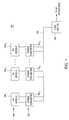
- FIG. 1is a block diagram of a system 100 for inverting solar generated DC power to AC power in accordance with one or more embodiments of the present invention. This diagram only portrays one variation of the myriad of possible system configurations. The present invention can function in a variety of environments and systems.
- the system 100comprises a plurality of power converters 102 1 , 102 2 . . . 102 n , collectively referred to as power converters 102 , a plurality of PV modules 104 1 , 104 2 . . . 104 n , collectively referred to as PV modules 104 , an AC bus 106 , and a load center 108 .
- Two input terminals of each power converter 102 1 , 102 2 . . . 102 nare coupled to two output terminals of a corresponding PV module 104 1 , 104 2 . . . 104 n ; i.e., the power converters 102 and the PV modules 104 are coupled in a one-to-one correspondence.
- the power converters 102each comprise a DC/DC conversion module coupled to a DC/AC inversion module, as described below with respect to FIG. 2 , for inverting the DC power generated by the PV modules 104 to AC power (i.e., AC current); alternatively, a single stage converter may convert DC directly to AC.
- the power converters 102are coupled to the AC bus 106 , which in turn is coupled to the load center 108 .
- the load center 108houses connections between incoming power lines from a commercial AC power grid distribution system (“grid”) and the AC bus 106 .
- the AC bus 106may be regulated by a battery-based (or other energy storage source) inverter and/or a rotating machine generator.
- the power converters 102meter out AC current that is in-phase with the AC power grid voltage, and the system 100 couples the generated AC power to the power grid via the load center 108 . Additionally or alternatively, the generated AC power may be supplied directly to commercial and/or residential systems via the load center 108 , and/or stored for later use (e.g., utilizing batteries, heated water, hydro pumping, H 2 O-to-hydrogen conversion, or the like).
- the power converter 102may not comprise a DC/DC converter (i.e., the power converter 102 comprises a single-stage DC/AC inverter) and a separate DC/DC converter may be coupled between each PV module 104 and each power converter 102 (i.e., one DC/DC converter per power converter/PV module pair).
- each of the power converters 102may be a DC/DC converter to convert the DC power generated by the PV modules 104 into DC at a different voltage.
- the converted DC power from the power converters 102may be supplied to commercial and/or residential DC systems, and/or the produced energy may be stored, for example, in storage batteries.
- multiple PV modules 104may be coupled to a single power converter 102 .
- the PV modules 104 of the system 100may be coupled to a single centralized power converter 102 that inverts the DC power from the PV modules 104 to AC power (i.e., a centralized inverter).
- a DC/DC convertermay be coupled between the PV modules 104 and the centralized power converter 102 ; alternatively, the centralized power converter 102 may be a DC/DC converter that converts the DC power generated by the PV modules 104 into DC at a different voltage.
- Any of the aforementioned configurations for converting DC to ACmay, in some embodiments, be comprised of a single DC/AC converter (i.e., a single stage DC/AC converter).
- the power converters 102may measure (for example, at intervals ranging from microseconds to tens of milliseconds) one or more of DC current and voltage from the PV modules 104 as well as AC current and voltage generated by the power converters 102 .
- the power converters 102may utilize at least a portion of the measured data to determine whether a DC arc fault is present and to control such an arc fault, as further described below.
- one or more signatures based on one or more signals of a power converter 102may be analyzed to determine whether a DC arc fault exists.
- the DC arc faultmay consist of a parallel arc across the power converter input terminals or across output terminals of the DC/DC conversion module of the power converter 102 .
- the DC arc faultmay consist of a series arc, for example, between one of the PV module output terminals and the coupled power conversion module input terminal, or between an output terminal of the power converter DC/DC conversion module and the coupled DC/AC inversion module terminal.
- FIG. 2is a block diagram of a power converter 102 in accordance with one or more embodiments of the present invention.
- the power converter 102comprises a power conversion circuit 202 , a controller 204 , a DC current sampler 206 , a DC voltage sampler 208 , an AC current sampler 210 , an AC voltage sampler 212 , and a DC input shorting mechanism 228 .
- the power conversion circuit 202comprises a DC/DC conversion module 230 and a DC/AC inversion module 232 .
- the DC/DC conversion module 230is coupled via two input terminals to the PV module 104 and via two output terminals to two input terminals of the DC/AC inversion module 232 , which is further coupled via two output terminals to the load center 108 .
- the DC/DC conversion module 230 and the DC/AC inversion module 232are each coupled to the controller 204 .
- the DC/DC conversion module 230 and the DC/AC inversion module 232act to convert the DC power from the PV modules 104 to a second DC power and then to an AC power, respectively, based on control signals from the controller 204 .
- the power conversion circuit 202converts DC current received from the PV module 104 to AC current with the controller 204 providing operative control and driving the power conversion circuit 202 to inject the generated AC output current in phase with the grid, as required by the relevant standards.
- the DC current sampler 206is coupled to an input terminal of the power conversion circuit 202 , and the DC voltage sampler 208 is coupled across the two input terminals of the power conversion circuit 202 .
- the AC current sampler 210is coupled to an output terminal of the power conversion circuit 202 , and the AC voltage sampler 212 is coupled across the two output terminals of the power conversion circuit 202 .
- the DC current sampler 206 , the DC voltage sampler 208 , the AC current sampler 210 , and the AC voltage sampler 212are each coupled to the controller 204 . Additionally, the DC input shorting mechanism 228 is coupled across the two power conversion circuit input terminals and to the controller 204 .
- the controller 204comprises at least one central processing unit (CPU) 214 , which is coupled to support circuits 216 and to a memory 218 .
- the CPU 214may comprise one or more conventionally available microprocessors or digital signal processors (DSPs); additionally or alternatively, the CPU 214 may include one or more application specific integrated circuits (ASIC).
- the support circuits 216are well known circuits used to promote functionality of the CPU 214 . Such circuits include, but are not limited to, a cache, power supplies, clock circuits, buses, network cards, input/output (I/O) circuits, and the like.
- the controller 204may be implemented using a general purpose processor that, when executing particular software, becomes a specific purpose processor for performing various embodiments of the present invention.
- the memory 218may comprise random access memory, read only memory, removable disk memory, flash memory, and various combinations of these types of memory.
- the memory 218is sometimes referred to as main memory and may, in part, be used as cache memory or buffer memory.
- the memory 218generally stores the operating system (OS) 220 of the controller 204 .
- the OS 220may be one of a number of commercially available operating systems such as, but not limited to, Linux, Real-Time Operating System (RTOS), and the like.
- the memory 218may store various forms of application software, such as a conversion control module 222 for controlling the operation of the power conversion circuit 202 .
- the conversion control module 222may receive the sampled DC and AC current and voltage values and utilize such data to provide the control and switching signals for the power conversion circuit 202 .
- the memory 218may comprise a database 224 for storing data, and a waveform processing module 226 for determining and managing DC arc faults (e.g., determining an arc type of series or parallel, determining voltage and current characteristics, and the like), as described in detail below.
- the database 224may store data related to the power conversion and/or data related to processing performed by the waveform processing module 226 ; for example, sampled DC and AC voltage and current values, computed current and/or voltage slope, computed changes in current and/or voltage slope over time, one or more thresholds for use in determining a DC arc fault event, DC arc fault event intervals, voltage and current correlations, and the like.
- the conversion control module 222 , database 224 , and/or waveform processing module 226 , or portions thereofmay be implemented in software, firmware, hardware, or a combination thereof.
- the DC current sampler 206 and the DC voltage sampler 208sample the DC current and voltage, respectively, generated by the PV module 104 and provide such sampled DC current and voltage values to the controller 204 .
- the AC current sampler 210 and the AC voltage sampler 212sample the AC current and voltage, respectively, at the output of the power conversion circuit 202 and provide such sampled AC current and voltage values to the controller 204 .
- the input signals to each of the samplersare filtered, for example via traditional analog filter techniques, digital signal processing, or similar techniques, and an analog-to-digital (A/D) conversion is performed utilizing standard A/D technology.
- the resulting instantaneous values, or samples, of DC current, DC voltage, AC current, and AC voltagemay be stored digitally in the database 224 for use by the waveform processing module 226 in determining whether a DC arc faults exists, as described below.
- the waveform processing module 226utilizes the sampled DC current and voltage values, which respectively define DC current and voltage signatures that characterize the DC circuit current and voltage over time, to determine an occurrence of a DC arc fault.
- the characteristics of an arc faultmay be extracted from the sampled current and voltage values by filtering unwanted artifacts from the sampled data and quantizing the dynamic behavior of the voltage and current values, as well as their relationship to each other.
- the waveform processing module 226analyzes, for example, generally every millisecond (msec) but as often as every microsecond ( ⁇ sec), the DC current and voltage signatures defined by at least a portion of the DC current and voltage samples in order to identify an arc fault; for such analysis, sampled current and/or voltage values may be averaged over a period of, for example, approximately 1 msec for analysis. In other embodiments, the signatures may be updated analyzed more or less frequently. In some embodiments, the waveform processing module 226 may analyze at least several tens of microseconds to a few milliseconds of data to identify characteristics indicating a DC arc fault (i.e., a series arc or a parallel arc).
- DC voltage and AC current signatures defined by sampled DC voltage and sampled AC current, respectivelymay be utilized to determine the presence of a DC arc fault (both current and voltage signatures are utilized to determine the existence of an arc fault).
- the waveform processing module 226analyzes the DC current signature for a change in polarity or a rapid change in slope (e.g., on the order of 0.1 amp/microsecond in some embodiments) indicating a potential DC arc fault.
- the DC current polarityshould always be positive and change in slope of DC current is normally due to changes in the commanded output current of the power converter 102 ; any fast change in current polarity or a change in slope that is not due to a change in commanded output current is suspect as being due to an arc fault. Slower changes may be due to changes in irradiance, and will not be detected as an arc fault.
- the waveform processing module 226compares the DC current signature to the DC voltage signature, e.g., the DC current and voltages are analyzed for coincidence and polarity that are not the result of changes in commanded output current of the power converter 102 . If, based on such comparison, it is determined that a DC arc fault signature match exists (i.e., one or more characteristics of the DC current and/or DC voltage signature are indicative of a DC arc fault), the DC current polarity is utilized to differentiate whether the DC circuit is experiencing a series or parallel arc event. In some embodiments, a DC arc fault signature match may be determined based on current and/or voltage changes, such as a maximum change in current and/or voltage over time.
- the waveform processing module 226causes the power converter 102 to cease power production. If the DC current polarity has a negative occurrence, a parallel arc has potentially occurred. During normal operation, i.e., when no arc faults exist, the DC current polarity should always be positive. However, when a parallel arc occurs, a large amount of negative current occurs for a time on the order of a millisecond (e.g., due to a violent discharge of one or more capacitors located across the DC input of the power converter; such a discharge does not occur in the event of a series arc).
- the waveform processing module 226drives the controller 204 to inhibit power production by the power converter 102 and to lock the DC input shorting mechanism 228 , which provides a short circuit across the input to the power conversion circuit 202 .
- the waveform processing module 226analyzes the DC current signature for DC current fluctuations, for example, as determined by comparison to a threshold (e.g., changes in current that are much more rapid than under normal operating conditions).
- di/dtwill depend on the length of the DC wire run, the normal DC voltage, and the power rating of the DC source as it interacts with the input characteristics of the power converter 102 ; di/dt in excess of the normal control mechanism (e.g., as compared to a threshold) may be indicative of an arc fault. If the DC current is not fluctuating, a parallel arc is confirmed and the DC input shorting mechanism 228 remains locked. If the DC current is fluctuating, the arc is a series arc and the waveform processing module 226 drives the controller 204 to unlock the DC input shorting mechanism 228 (i.e., to open the DC terminals) while continuing to lock out the power production.
- the power converter 102may employ an auto-restart technique for attempting to restart the power converter 102 and resume power production after some period of time, for example on the order of a few minutes subsequent to the arc detection and termination of power production.
- the power converter 102may attempt such a restart one or more times before sustaining the termination of power production in the event that the arc fault remains or recurs.
- occurrence of a DC arc faultmay be determined based on a power signature generated from the sampled DC current and voltage data, or from the sampled AC current and DC voltage data.
- FIG. 3is a flow diagram of a method 300 for identifying and managing a DC arc fault in a power conversion system in accordance with one or more embodiments of the present invention.
- the power conversion systemcomprises one or more power converters, such as DC/AC inverters, coupled to one or more PV modules.
- the DC/AC invertersmay each comprise a DC/DC conversion module followed by a DC/AC inversion module to invert the DC power generated by the PV modules to AC power (e.g., the power converters 102 comprising the DC/DC conversion modules 230 and the DC/AC inversion modules 232 ); alternatively, the DC/AC inverters may utilize a single DC/AC conversion stage.
- the generated AC powermay then be coupled to an AC power grid, provided directly to commercial and/or residential AC powered devices, and/or stored for later use (e.g., utilizing batteries, heated water, hydro pumping, H 2 O-to-hydrogen conversion, or the like).
- the power convertersmay be DC/DC converters for converting the DC power generated by the PV modules into DC at a different voltage.
- a signature based on one or more signals of a power convertermay be analyzed to determine whether a DC arc fault exists.
- a power convertere.g., DC current, DC voltage, AC current, AC voltage, DC power, AC power, a derivative of any of such signals, a combination of any of such signals, or the like
- the method 300begins at step 302 and proceeds to step 304 , where DC current and DC voltage from the PV module(s) coupled to a power converter in the power conversion system are sampled.
- the measured DC current and DC voltagemay be filtered, for example by traditional analog filter techniques, digital signal processing, or similar techniques, and an A/D conversion may be performed utilizing standard A/D technology.
- the resulting instantaneous DC current value and instantaneous DC voltage value(i.e., the DC current and voltage samples) may be stored, for example, within a memory of the power converter, such as memory 218 .
- AC current and/or AC voltage generated by the power convertermay be analogously sampled and stored for use in identifying and managing DC arc faults, such as a DC arc fault at the input or the output of the power converter's DC/DC conversion module.
- a DC current signatureis analyzed to determine whether a potential arc has occurred.
- the DC current signatureis defined by the sampled DC current and characterizes the DC current over time.
- the DC current signatureis analyzed for a rapid change in slope (e.g., on the order of 0.1 amp/microsecond in some embodiments) or a change in polarity to indicate a potential arc, as previously described.
- the method 300proceeds to step 310 , where a determination is made whether a potential arc has been identified based on the analysis of step 308 . If the result of such determination is no, the method 300 proceeds to step 334 . At step 334 , a determination is made whether to continue operation. If, at step 334 , the result of the determination is yes, the method 300 returns to step 304 ; if the result of the determination is no, the method 300 proceeds to step 336 where it ends.
- the determination in step 334may be based upon the repetitive occurrence of the indication of an arc fault which may indicate an intermittent fault, or may indicate a failure in the measurement and control system.
- the method 300proceeds to step 312 .
- the DC current signatureis compared to a DC voltage signature.
- the DC voltage signatureis defined by the sampled DC voltage and characterizes the DC voltage over time.
- the DC current and voltage signaturesare compared to identify characteristics consistent with a DC arc fault signature (i.e., to determine whether a DC arc fault signature match exists).
- the DC current and voltage signaturesare analyzed for coincidence and polarity that are not the result of changes in commanded output current of the power converter.
- step 314a determination is made whether a DC arc fault signature match exists based on the comparison of step 312 . If the result of such determination is no, the method 300 proceeds to step 334 ; if the result of such determination is yes, the method 300 proceeds to step 316 .
- the DC current polarityis utilized to differentiate whether the DC circuit is experiencing a series or parallel arc event. If the DC current polarity has remained positive, it is determined that a series arc has occurred; if the DC current polarity has a negative occurrence, it is determined that a parallel arc has potentially occurred.
- a determinationis made whether a series or a parallel arc is identified based on the analysis of step 316 . If the result of such determination is that a series arc has occurred, the method 300 proceeds to step 330 .
- step 330power production by the power converter is inhibited; the method 300 then proceeds to step 336 where it ends.
- step 318the method 300 proceeds to step 320 .
- step 320power production by the power converter is inhibited.
- step 322DC terminals at the input of the power converter are shorted, for example by locking a DC input shorting mechanism (e.g., DC input shorting mechanism 228 ).
- step 324the DC current signature is analyzed for DC current fluctuations, for example as determined by comparison to a threshold (e.g., changes in current that are much more rapid than under normal operating conditions); if the DC current is not fluctuating, a parallel arc is confirmed.
- a thresholde.g., changes in current that are much more rapid than under normal operating conditions
- step 326a determination is made whether the parallel arc is confirmed based on the analysis of step 324 . If the result of such determination is no, the arc is determined to be a series arc and the method 300 proceeds to step 328 , where the shorted DC terminals are opened, for example by unlocking the DC input shorting mechanism. The method 300 then proceeds to step 330 and the power production by the power converter remains locked out. If, at step 326 , the result of such determination is yes (i.e., a parallel arc is confirmed), the method 300 proceeds to step 332 , where the DC input terminals remain shorted. The method 300 then proceeds to step 336 where it ends.
- the method 300may additionally or alternatively utilize the sampled AC current data and/or the sampled AC voltage data for determining and managing an occurrence of a DC arc fault.
- the method 300may comprise steps for an auto-restart technique for attempting to restart the power converter and resume power production after some period of time, for example on the order of a few minutes subsequent to the arc detection and termination of power production. Such a restart may be attempted one or more times before sustaining the termination of power production in the event that the arc fault remains or recurs.
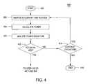
- FIG. 4is a flow diagram of a method 400 for identifying a potential DC arc fault based on power changes in a power conversion system in accordance with one or more embodiments of the present invention.
- the power conversion systemcomprises one or more power converters, such as DC/AC inverters, coupled to one or more PV modules.
- the DC/AC invertersmay each comprise a DC/DC conversion module followed by a DC/AC inversion module to invert the DC power generated by the PV modules to AC power (e.g., the power converters 102 comprising the DC/DC conversion modules 230 and the DC/AC inversion modules 232 ).
- the generated AC powermay then be coupled to an AC power grid, provided directly to commercial and/or residential AC powered devices, and/or stored for later use (e.g., utilizing batteries, heated water, hydro pumping, H 2 O-to-hydrogen conversion, or the like).
- the power convertersmay be DC/DC converters for converting the DC power generated by the PV modules into DC at a different voltage.
- the method 400begins at step 402 and proceeds to step 404 , where DC current and DC voltage from the PV module(s) coupled to a power converter in the power conversion system are sampled.
- the measured DC current and DC voltagemay be filtered, for example by traditional analog filter techniques, digital signal processing, or similar techniques, and an A/D conversion may be performed utilizing standard A/D technology.
- the resulting instantaneous DC current and voltage valuesare used to compute an instantaneous DC power.
- the instantaneous DC power value, as well as the instantaneous DC current and voltage values,may be stored, for example within a memory of the power converter, such as memory 218 .
- AC current and AC voltage from the power convertermay be analogously sampled and utilized to obtain AC power measurements for identifying DC arc faults, such as a DC arc fault at the input or the output of the power converter's DC/DC conversion module.
- a DC power signatureis analyzed to determine whether a potential arc has occurred.
- the DC power signatureis defined by the instantaneous DC power values and characterizes the DC power over time.
- a rapid power decrease in the DC power signaturefor example as determined by comparison to a threshold (e.g., a microsecond change in power more than, for example, a few percent of the rated power that does not coincide with a change in current command from the power converter power control system) indicates a potential arc; additionally or alternatively, the power change dp/dt may be evaluated for determining whether a potential arc has occurred.
- step 412a determination is made whether a potential DC arc fault has been identified based on the analysis of step 410 . If the result of such determination is no (i.e., no potential DC arc fault), the method 400 proceeds to step 414 , where a determination is made whether to continue operation. If the result of such determination at step 414 is yes (i.e., continue operation), the method 400 returns to step 404 . If the result of such determination is no, the method 400 proceeds to step 416 where it ends.
- step 412the method 400 proceeds to step 312 of the method 300 .
Landscapes
- Physics & Mathematics (AREA)
- General Physics & Mathematics (AREA)
- Inverter Devices (AREA)
- Dc-Dc Converters (AREA)
- Testing Of Short-Circuits, Discontinuities, Leakage, Or Incorrect Line Connections (AREA)
- Testing Relating To Insulation (AREA)
- Emergency Protection Circuit Devices (AREA)
- Arc Welding Control (AREA)
- Testing Electric Properties And Detecting Electric Faults (AREA)
Abstract
Description
Claims (17)
Priority Applications (2)
| Application Number | Priority Date | Filing Date | Title |
|---|---|---|---|
| US12/804,541US8179147B2 (en) | 2009-07-23 | 2010-07-23 | Method and apparatus for detection and control of dc arc faults |
| US13/453,545US9478967B2 (en) | 2009-07-23 | 2012-04-23 | Method and apparatus for detection and control of DC arc faults |
Applications Claiming Priority (2)
| Application Number | Priority Date | Filing Date | Title |
|---|---|---|---|
| US22794909P | 2009-07-23 | 2009-07-23 | |
| US12/804,541US8179147B2 (en) | 2009-07-23 | 2010-07-23 | Method and apparatus for detection and control of dc arc faults |
Related Child Applications (1)
| Application Number | Title | Priority Date | Filing Date |
|---|---|---|---|
| US13/453,545ContinuationUS9478967B2 (en) | 2009-07-23 | 2012-04-23 | Method and apparatus for detection and control of DC arc faults |
Publications (2)
| Publication Number | Publication Date |
|---|---|
| US20110019444A1 US20110019444A1 (en) | 2011-01-27 |
| US8179147B2true US8179147B2 (en) | 2012-05-15 |
Family
ID=43497205
Family Applications (2)
| Application Number | Title | Priority Date | Filing Date |
|---|---|---|---|
| US12/804,541Active2030-10-29US8179147B2 (en) | 2009-07-23 | 2010-07-23 | Method and apparatus for detection and control of dc arc faults |
| US13/453,545Active2033-01-10US9478967B2 (en) | 2009-07-23 | 2012-04-23 | Method and apparatus for detection and control of DC arc faults |
Family Applications After (1)
| Application Number | Title | Priority Date | Filing Date |
|---|---|---|---|
| US13/453,545Active2033-01-10US9478967B2 (en) | 2009-07-23 | 2012-04-23 | Method and apparatus for detection and control of DC arc faults |
Country Status (7)
| Country | Link |
|---|---|
| US (2) | US8179147B2 (en) |
| EP (2) | EP2741388B1 (en) |
| JP (1) | JP5524335B2 (en) |
| KR (1) | KR20120039036A (en) |
| AU (1) | AU2010275466B2 (en) |
| CA (1) | CA2758815A1 (en) |
| WO (1) | WO2011011711A2 (en) |
Cited By (70)
| Publication number | Priority date | Publication date | Assignee | Title |
|---|---|---|---|---|
| US20110161722A1 (en)* | 2009-12-29 | 2011-06-30 | Tigo Energy | Systems and Methods for a Communication Protocol Between a Local Controller and a Master Controller |
| US20110260866A1 (en)* | 2010-04-22 | 2011-10-27 | Tigo Energy | Enhanced System and Method for Theft Prevention in a Solar Power Array During Nonoperative Periods |
| US20130088802A1 (en)* | 2010-06-14 | 2013-04-11 | Abb Research Ltd | Fault protection of hvdc transmission lines |
| EP2806518A1 (en)* | 2013-05-24 | 2014-11-26 | DET International Holding Limited | Serial arc detection based on harmonic content of DC current signal |
| US9124139B2 (en) | 2010-01-08 | 2015-09-01 | Tigo Energy, Inc. | Systems and methods for an identification protocol between a local controller coupled to control a solar module and a master controller |
| US9130401B2 (en) | 2006-12-06 | 2015-09-08 | Solaredge Technologies Ltd. | Distributed power harvesting systems using DC power sources |
| US9235228B2 (en) | 2012-03-05 | 2016-01-12 | Solaredge Technologies Ltd. | Direct current link circuit |
| US9291696B2 (en) | 2007-12-05 | 2016-03-22 | Solaredge Technologies Ltd. | Photovoltaic system power tracking method |
| US9318974B2 (en) | 2014-03-26 | 2016-04-19 | Solaredge Technologies Ltd. | Multi-level inverter with flying capacitor topology |
| US9362743B2 (en) | 2008-05-05 | 2016-06-07 | Solaredge Technologies Ltd. | Direct current power combiner |
| US9368964B2 (en) | 2006-12-06 | 2016-06-14 | Solaredge Technologies Ltd. | Distributed power system using direct current power sources |
| US20160181799A1 (en)* | 2013-08-26 | 2016-06-23 | Mitsubishi Electric Corporation | Dc power generation system and protection method for dc power generation system |
| US9401599B2 (en) | 2010-12-09 | 2016-07-26 | Solaredge Technologies Ltd. | Disconnection of a string carrying direct current power |
| US9407161B2 (en) | 2007-12-05 | 2016-08-02 | Solaredge Technologies Ltd. | Parallel connected inverters |
| US9537445B2 (en) | 2008-12-04 | 2017-01-03 | Solaredge Technologies Ltd. | Testing of a photovoltaic panel |
| US9543889B2 (en) | 2006-12-06 | 2017-01-10 | Solaredge Technologies Ltd. | Distributed power harvesting systems using DC power sources |
| US9548619B2 (en) | 2013-03-14 | 2017-01-17 | Solaredge Technologies Ltd. | Method and apparatus for storing and depleting energy |
| US9559516B2 (en) | 2013-03-13 | 2017-01-31 | Astec International Limited | Arc prevention in DC power systems |
| US9590526B2 (en) | 2006-12-06 | 2017-03-07 | Solaredge Technologies Ltd. | Safety mechanisms, wake up and shutdown methods in distributed power installations |
| US9644993B2 (en) | 2006-12-06 | 2017-05-09 | Solaredge Technologies Ltd. | Monitoring of distributed power harvesting systems using DC power sources |
| US9647442B2 (en) | 2010-11-09 | 2017-05-09 | Solaredge Technologies Ltd. | Arc detection and prevention in a power generation system |
| US9673711B2 (en) | 2007-08-06 | 2017-06-06 | Solaredge Technologies Ltd. | Digital average input current control in power converter |
| US9680304B2 (en) | 2006-12-06 | 2017-06-13 | Solaredge Technologies Ltd. | Method for distributed power harvesting using DC power sources |
| US9702959B2 (en) | 2015-09-24 | 2017-07-11 | Earth Networks, Inc. | Remote sensing to derive calibrated power measurements |
| US9780516B2 (en) | 2014-01-02 | 2017-10-03 | International Business Machines Corporation | Power interconnection with current surge mitigation |
| US9812984B2 (en) | 2012-01-30 | 2017-11-07 | Solaredge Technologies Ltd. | Maximizing power in a photovoltaic distributed power system |
| US9819178B2 (en) | 2013-03-15 | 2017-11-14 | Solaredge Technologies Ltd. | Bypass mechanism |
| US9831824B2 (en) | 2007-12-05 | 2017-11-28 | SolareEdge Technologies Ltd. | Current sensing on a MOSFET |
| US9853538B2 (en) | 2007-12-04 | 2017-12-26 | Solaredge Technologies Ltd. | Distributed power harvesting systems using DC power sources |
| US9853565B2 (en) | 2012-01-30 | 2017-12-26 | Solaredge Technologies Ltd. | Maximized power in a photovoltaic distributed power system |
| US9866098B2 (en) | 2011-01-12 | 2018-01-09 | Solaredge Technologies Ltd. | Serially connected inverters |
| US9869701B2 (en) | 2009-05-26 | 2018-01-16 | Solaredge Technologies Ltd. | Theft detection and prevention in a power generation system |
| US9876430B2 (en) | 2008-03-24 | 2018-01-23 | Solaredge Technologies Ltd. | Zero voltage switching |
| US9923516B2 (en) | 2012-01-30 | 2018-03-20 | Solaredge Technologies Ltd. | Photovoltaic panel circuitry |
| US9941813B2 (en) | 2013-03-14 | 2018-04-10 | Solaredge Technologies Ltd. | High frequency multi-level inverter |
| US9960731B2 (en) | 2006-12-06 | 2018-05-01 | Solaredge Technologies Ltd. | Pairing of components in a direct current distributed power generation system |
| US9960667B2 (en) | 2006-12-06 | 2018-05-01 | Solaredge Technologies Ltd. | System and method for protection during inverter shutdown in distributed power installations |
| US9966766B2 (en) | 2006-12-06 | 2018-05-08 | Solaredge Technologies Ltd. | Battery power delivery module |
| US9995796B1 (en) | 2013-05-23 | 2018-06-12 | National Technology & Engineering Solutions Of Sandia, Llc | Identifying an arc-fault type in photovoltaic arrays |
| US10078105B2 (en) | 2015-09-23 | 2018-09-18 | Abb Schweiz Ag | Electrical system with arc fault detection |
| US10097108B2 (en) | 2014-12-16 | 2018-10-09 | Abb Schweiz Ag | Energy panel arrangement power dissipation |
| US10103537B2 (en) | 2015-12-16 | 2018-10-16 | Ge Energy Power Conversion Technology Ltd | Ground fault detection and interrupt system |
| US10115841B2 (en) | 2012-06-04 | 2018-10-30 | Solaredge Technologies Ltd. | Integrated photovoltaic panel circuitry |
| US10135247B2 (en) | 2013-10-17 | 2018-11-20 | General Electric Company | Methods and systems for integrated Volt/VAr control in electric network |
| US10230310B2 (en) | 2016-04-05 | 2019-03-12 | Solaredge Technologies Ltd | Safety switch for photovoltaic systems |
| US10348094B2 (en) | 2015-01-28 | 2019-07-09 | Abb Schweiz Ag | Energy panel arrangement shutdown |
| US10396662B2 (en) | 2011-09-12 | 2019-08-27 | Solaredge Technologies Ltd | Direct current link circuit |
| US10404060B2 (en) | 2015-02-22 | 2019-09-03 | Abb Schweiz Ag | Photovoltaic string reverse polarity detection |
| US10601234B2 (en)* | 2017-08-15 | 2020-03-24 | Tesla, Inc. | Arc fault detection for battery packs in energy generation systems |
| US10673222B2 (en) | 2010-11-09 | 2020-06-02 | Solaredge Technologies Ltd. | Arc detection and prevention in a power generation system |
| US10673229B2 (en) | 2010-11-09 | 2020-06-02 | Solaredge Technologies Ltd. | Arc detection and prevention in a power generation system |
| US10931119B2 (en) | 2012-01-11 | 2021-02-23 | Solaredge Technologies Ltd. | Photovoltaic module |
| US10985695B2 (en) | 2018-08-28 | 2021-04-20 | Analog Devices International Unlimited Company | DC arc detection and photovoltaic plant profiling system |
| US11018623B2 (en) | 2016-04-05 | 2021-05-25 | Solaredge Technologies Ltd. | Safety switch for photovoltaic systems |
| US11177663B2 (en) | 2016-04-05 | 2021-11-16 | Solaredge Technologies Ltd. | Chain of power devices |
| US11264947B2 (en) | 2007-12-05 | 2022-03-01 | Solaredge Technologies Ltd. | Testing of a photovoltaic panel |
| US11296650B2 (en) | 2006-12-06 | 2022-04-05 | Solaredge Technologies Ltd. | System and method for protection during inverter shutdown in distributed power installations |
| US11309832B2 (en) | 2006-12-06 | 2022-04-19 | Solaredge Technologies Ltd. | Distributed power harvesting systems using DC power sources |
| US11482850B2 (en) | 2017-07-31 | 2022-10-25 | Ellenberger & Poensgen Gmbh | Method for detecting accidental arcs during the charging of electrical battery systems |
| US11569660B2 (en) | 2006-12-06 | 2023-01-31 | Solaredge Technologies Ltd. | Distributed power harvesting systems using DC power sources |
| US11569659B2 (en) | 2006-12-06 | 2023-01-31 | Solaredge Technologies Ltd. | Distributed power harvesting systems using DC power sources |
| US11687112B2 (en) | 2006-12-06 | 2023-06-27 | Solaredge Technologies Ltd. | Distributed power harvesting systems using DC power sources |
| US11728768B2 (en) | 2006-12-06 | 2023-08-15 | Solaredge Technologies Ltd. | Pairing of components in a direct current distributed power generation system |
| US11735910B2 (en) | 2006-12-06 | 2023-08-22 | Solaredge Technologies Ltd. | Distributed power system using direct current power sources |
| US11855231B2 (en) | 2006-12-06 | 2023-12-26 | Solaredge Technologies Ltd. | Distributed power harvesting systems using DC power sources |
| US11881814B2 (en) | 2005-12-05 | 2024-01-23 | Solaredge Technologies Ltd. | Testing of a photovoltaic panel |
| US11888387B2 (en) | 2006-12-06 | 2024-01-30 | Solaredge Technologies Ltd. | Safety mechanisms, wake up and shutdown methods in distributed power installations |
| US12057807B2 (en) | 2016-04-05 | 2024-08-06 | Solaredge Technologies Ltd. | Chain of power devices |
| US12081011B2 (en) | 2017-05-23 | 2024-09-03 | Pass & Seymour, Inc. | Arc fault circuit interrupter |
| US12418177B2 (en) | 2009-10-24 | 2025-09-16 | Solaredge Technologies Ltd. | Distributed power system using direct current power sources |
Families Citing this family (92)
| Publication number | Priority date | Publication date | Assignee | Title |
|---|---|---|---|---|
| US7994657B2 (en)* | 2006-12-22 | 2011-08-09 | Solarbridge Technologies, Inc. | Modular system for unattended energy generation and storage |
| FR2912848B1 (en)* | 2007-02-20 | 2010-09-17 | Commissariat Energie Atomique | VOLTAGE LIMITER AND PROTECTION OF A PHOTOVOLTAIC MODULE |
| US7755916B2 (en) | 2007-10-11 | 2010-07-13 | Solarbridge Technologies, Inc. | Methods for minimizing double-frequency ripple power in single-phase power conditioners |
| EP2225778B1 (en) | 2007-12-05 | 2019-06-26 | Solaredge Technologies Ltd. | Testing of a photovoltaic panel |
| EP2602831B1 (en) | 2009-05-22 | 2014-07-16 | Solaredge Technologies Ltd. | Electrically isolated heat dissipating junction box |
| US8482947B2 (en) | 2009-07-31 | 2013-07-09 | Solarbridge Technologies, Inc. | Apparatus and method for controlling DC-AC power conversion |
| AT509251A1 (en)* | 2009-08-14 | 2011-07-15 | Fronius Int Gmbh | 4 EXPERTS IN THE FIELD OF ARC FLASH IN PHOTOVOLTAIC PLANTS AND ONE SUCH PHOTOVOLTAIC PLANT |
| US8099197B2 (en)* | 2009-08-18 | 2012-01-17 | Enphase Energy, Inc. | Method and system for distributed energy generator message aggregation |
| US8207637B2 (en)* | 2009-10-09 | 2012-06-26 | Solarbridge Technologies, Inc. | System and apparatus for interconnecting an array of power generating assemblies |
| US8462518B2 (en)* | 2009-10-12 | 2013-06-11 | Solarbridge Technologies, Inc. | Power inverter docking system for photovoltaic modules |
| US8710699B2 (en) | 2009-12-01 | 2014-04-29 | Solaredge Technologies Ltd. | Dual use photovoltaic system |
| US8824178B1 (en) | 2009-12-31 | 2014-09-02 | Solarbridge Technologies, Inc. | Parallel power converter topology |
| US9806445B2 (en) | 2010-01-25 | 2017-10-31 | Enphase Energy, Inc. | Method and apparatus for interconnecting distributed power sources |
| EP2529450A4 (en) | 2010-01-25 | 2014-10-22 | Enphase Energy Inc | Method and apparatus for interconnecting distributed power sources |
| US8766696B2 (en) | 2010-01-27 | 2014-07-01 | Solaredge Technologies Ltd. | Fast voltage level shifter circuit |
| US8717720B2 (en) | 2010-07-20 | 2014-05-06 | Siemens Industry, Inc. | Systems and methods for providing arc fault and/or ground fault protection for distributed generation sources |
| DE102011008140A1 (en) | 2010-08-31 | 2012-03-01 | Ellenberger & Poensgen Gmbh | Method and device for switching a DC voltage system |
| USD666974S1 (en) | 2010-09-24 | 2012-09-11 | Solarbridge Technologies, Inc. | Y-junction interconnect module |
| US9160408B2 (en) | 2010-10-11 | 2015-10-13 | Sunpower Corporation | System and method for establishing communication with an array of inverters |
| US8503200B2 (en) | 2010-10-11 | 2013-08-06 | Solarbridge Technologies, Inc. | Quadrature-corrected feedforward control apparatus and method for DC-AC power conversion |
| US8279649B2 (en) | 2010-10-11 | 2012-10-02 | Solarbridge Technologies, Inc. | Apparatus and method for controlling a power inverter |
| CN101976852A (en)* | 2010-11-02 | 2011-02-16 | 深圳市合兴加能科技有限公司 | Photovoltaic power supply system structure and method thereof |
| US9467063B2 (en) | 2010-11-29 | 2016-10-11 | Sunpower Corporation | Technologies for interleaved control of an inverter array |
| US8842454B2 (en) | 2010-11-29 | 2014-09-23 | Solarbridge Technologies, Inc. | Inverter array with localized inverter control |
| CN103548226B (en)* | 2011-02-28 | 2015-12-02 | Sma太阳能技术股份公司 | For the method and system of arc fault in testing circuit |
| US8611107B2 (en) | 2011-04-27 | 2013-12-17 | Solarbridge Technologies, Inc. | Method and system for controlling a multi-stage power inverter |
| US8193788B2 (en) | 2011-04-27 | 2012-06-05 | Solarbridge Technologies, Inc. | Method and device for controlling a configurable power supply to provide AC and/or DC power output |
| US9065354B2 (en) | 2011-04-27 | 2015-06-23 | Sunpower Corporation | Multi-stage power inverter for power bus communication |
| FR2977677B1 (en) | 2011-07-04 | 2013-08-23 | Commissariat Energie Atomique | DETECTION OF ELECTRIC ARCS IN PHOTOVOLTAIC FACILITIES |
| CN103597363A (en)* | 2011-07-04 | 2014-02-19 | Sma太阳能技术股份公司 | Method and system for detecting an arc fault in a photovoltaic power system |
| US8780592B1 (en) | 2011-07-11 | 2014-07-15 | Chilicon Power, LLC | Systems and methods for increasing output current quality, output power, and reliability of grid-interactive inverters |
| US8922185B2 (en) | 2011-07-11 | 2014-12-30 | Solarbridge Technologies, Inc. | Device and method for global maximum power point tracking |
| JP5957191B2 (en)* | 2011-08-30 | 2016-07-27 | 一般財団法人電力中央研究所 | Converter, converter control method, and converter control program |
| US8284574B2 (en) | 2011-10-17 | 2012-10-09 | Solarbridge Technologies, Inc. | Method and apparatus for controlling an inverter using pulse mode control |
| JP5888972B2 (en)* | 2011-12-22 | 2016-03-22 | 三菱電機株式会社 | Solar power system |
| EP2662844A2 (en)* | 2012-05-11 | 2013-11-13 | Area Energy Limited | Alarm apparatus for connection to a photovoltaic array |
| EP3499695B1 (en) | 2012-05-25 | 2024-09-18 | Solaredge Technologies Ltd. | Circuit for interconnected direct current power sources |
| USD707632S1 (en) | 2012-06-07 | 2014-06-24 | Enphase Energy, Inc. | Trunk connector |
| USD708143S1 (en) | 2012-06-07 | 2014-07-01 | Enphase Energy, Inc. | Drop cable connector |
| US9276635B2 (en) | 2012-06-29 | 2016-03-01 | Sunpower Corporation | Device, system, and method for communicating with a power inverter using power line communications |
| DE102012110687A1 (en)* | 2012-08-27 | 2014-05-15 | Newtos Ag | Method for arc detection in photovoltaic systems |
| US9465909B2 (en)* | 2012-11-16 | 2016-10-11 | Sensata Technologies, Inc. | Systems and methods of discriminating DC arcs and load switching noise |
| US10338121B2 (en) | 2012-11-23 | 2019-07-02 | Elevare Energy Ip Pty Ltd | Electrical supply system |
| US9564835B2 (en) | 2013-03-15 | 2017-02-07 | Sunpower Corporation | Inverter communications using output signal |
| US9584044B2 (en) | 2013-03-15 | 2017-02-28 | Sunpower Corporation | Technologies for converter topologies |
| EP2779340B1 (en)* | 2013-03-15 | 2018-11-07 | Sensata Technologies, Inc. | Home run arc detection at the photovoltaic string level using multiple current sensors |
| GB2513197A (en)* | 2013-04-19 | 2014-10-22 | Dale Read | Energy reporting unit |
| JP6000193B2 (en)* | 2013-06-14 | 2016-09-28 | 三菱電機株式会社 | DC arc detector |
| FR3010261B1 (en) | 2013-08-29 | 2015-10-02 | Commissariat Energie Atomique | DETECTION OF AN ELECTRICAL ARC IN PARALLEL ON THE MAIN TERMINALS OF A PHOTOVOLTAIC INSTALLATION |
| FR3010260B1 (en) | 2013-08-29 | 2015-10-02 | Commissariat Energie Atomique | DETECTION OF ELECTRIC ARCS IN PHOTOVOLTAIC FACILITIES |
| CN104426157B (en)* | 2013-09-10 | 2017-04-19 | 台达电子企业管理(上海)有限公司 | Energy storage module and energy storage device |
| JP2015155889A (en)* | 2013-12-23 | 2015-08-27 | センサータ テクノロジーズ マサチューセッツ インコーポレーテッド | Improved noise propagation immunity of a multi-string arc fault detection device |
| JP6246062B2 (en)* | 2014-04-30 | 2017-12-13 | 三菱電機株式会社 | DC power generation system and method for protecting DC power generation system |
| JP6272135B2 (en)* | 2014-05-20 | 2018-01-31 | 三菱電機株式会社 | Power consumption system, leakage detection method, and program |
| US9853443B2 (en)* | 2014-06-26 | 2017-12-26 | Solantro Semiconductor Corp. | ARC fault detection and extinguishing |
| CN204333950U (en)* | 2014-12-22 | 2015-05-13 | 安徽凯川电力保护设备有限公司 | A kind of electric power system two CSTR single-phase earthing extinguishing arc equipment |
| US9768605B2 (en)* | 2014-12-29 | 2017-09-19 | Eaton Corporation | Arc fault detection system and method and circuit interrupter employing same |
| CN104601105B (en)* | 2015-01-08 | 2017-04-26 | 西安交通大学 | Arc detection method for fault of photovoltaic system under abnormal light condition |
| CN104811135B (en)* | 2015-04-16 | 2017-04-26 | 西安交通大学 | Photovoltaic system fault arc detection method under common-mode signal interference condition |
| US10374424B2 (en)* | 2015-08-18 | 2019-08-06 | Argentum Electronics, Inc. | Wide range power distribution systems and methods |
| US20180048148A1 (en)* | 2015-08-18 | 2018-02-15 | Argentum Electronics, Inc. | Wide range power combiner |
| US11081608B2 (en) | 2016-03-03 | 2021-08-03 | Solaredge Technologies Ltd. | Apparatus and method for determining an order of power devices in power generation systems |
| CN107153212B (en) | 2016-03-03 | 2023-07-28 | 太阳能安吉科技有限公司 | Method for mapping a power generation facility |
| US10599113B2 (en) | 2016-03-03 | 2020-03-24 | Solaredge Technologies Ltd. | Apparatus and method for determining an order of power devices in power generation systems |
| JP6037071B1 (en)* | 2016-03-07 | 2016-11-30 | オムロン株式会社 | Arc detector |
| DE102016209443B4 (en) | 2016-05-31 | 2021-06-10 | Siemens Aktiengesellschaft | Arc fault detection unit |
| DE102016209444A1 (en)* | 2016-05-31 | 2017-11-30 | Siemens Aktiengesellschaft | Störlichtbogenerkennungseinheit |
| EP3446387B1 (en)* | 2016-05-31 | 2023-05-31 | Siemens Aktiengesellschaft | Fault-arc identification unit |
| US11088527B2 (en) | 2016-05-31 | 2021-08-10 | Siemens Aktiengesellschaft | Arc fault identification unit |
| CN109478773B (en)* | 2016-05-31 | 2020-09-04 | 西门子股份公司 | Arc fault identification unit |
| US11088526B2 (en) | 2016-05-31 | 2021-08-10 | Siemens Aktiengesellschaft | Arcing fault recognition unit |
| CN108333491B (en)* | 2017-01-17 | 2022-05-27 | 太阳能安吉科技有限公司 | Arc Detection and Prevention in Power Generation System |
| KR101881411B1 (en) | 2017-01-18 | 2018-07-24 | (주)다쓰테크 | Arc detection and shutdown method in pv system and pv energy storage system |
| JP6673237B2 (en)* | 2017-01-23 | 2020-03-25 | オムロン株式会社 | Arc detector |
| JP6760105B2 (en)* | 2017-01-25 | 2020-09-23 | 富士電機機器制御株式会社 | Arc failure detector |
| JP6807552B2 (en) | 2017-02-14 | 2021-01-06 | パナソニックIpマネジメント株式会社 | Arc detection circuit, switch system, power conditioner system and arc detection method |
| CN107086855B (en)* | 2017-04-25 | 2018-10-30 | 西安交通大学 | The photovoltaic system fault arc detection method of more time-frequency characteristics is merged in a kind of machine learning |
| US10509067B2 (en)* | 2017-07-06 | 2019-12-17 | Mersen Usa Newburyport-Ma, Llc | Method for AC arc fault detection using multidimensional energy points |
| US11063435B2 (en) | 2017-08-07 | 2021-07-13 | Raytheon Company | Energy-based adaptive stability control system |
| EP3664239A1 (en)* | 2018-12-07 | 2020-06-10 | GE Energy Power Conversion Technology Ltd. | Methods of controlling an electrical system to extinguish an electric arc, and electrical systems |
| US11349292B2 (en) | 2019-04-09 | 2022-05-31 | Raytheon Company | Arc flash protection of power systems |
| AU2020345857B2 (en) | 2019-09-09 | 2022-05-12 | Elexsys Ip Pty Ltd | Electrical power regulating apparatus |
| EP4028846A4 (en) | 2019-09-09 | 2024-03-06 | Elexsys IP Pty Ltd | Two-way electrical power distribution network |
| US11067638B2 (en)* | 2019-12-12 | 2021-07-20 | Sma Solar Technology Ag | Method of and system for detecting a serial arc fault in a power circuit |
| JP7417963B2 (en) | 2020-08-26 | 2024-01-19 | パナソニックIpマネジメント株式会社 | Arc detection device, arc detection system, arc detection method, and program |
| US11784555B2 (en)* | 2020-09-25 | 2023-10-10 | Enphase Energy, Inc. | High-power microinverter and system |
| WO2022129554A1 (en)* | 2020-12-18 | 2022-06-23 | Craftstrom Limited | Overload protection method and system |
| EP4109695A1 (en)* | 2021-06-23 | 2022-12-28 | Energysquare | Charging device comprising a current surge protection circuit |
| US12038467B2 (en)* | 2022-02-07 | 2024-07-16 | General Electric Company | Noise tolerant electrical discharge detection |
| CN114755546B (en)* | 2022-06-14 | 2022-08-26 | 锦浪科技股份有限公司 | Method and device for detecting direct-current fault arc of photovoltaic system and photovoltaic system |
| WO2024048019A1 (en)* | 2022-09-02 | 2024-03-07 | 株式会社カネカ | Electric power supply system |
| CN117410930A (en)* | 2023-11-23 | 2024-01-16 | 阳光电源股份有限公司 | Arc fault processing method, inverter and photovoltaic system |
Citations (16)
| Publication number | Priority date | Publication date | Assignee | Title |
|---|---|---|---|---|
| US6833713B2 (en) | 2003-01-31 | 2004-12-21 | Delphi Technologies, Inc. | Smart wire harness for an electrical circuit |
| US7009406B2 (en) | 2003-04-24 | 2006-03-07 | Delphi Technologies, Inc. | Arc fault detector and method |
| EP1657797A1 (en) | 2004-11-13 | 2006-05-17 | SMA Technologie AG | Protection device for apparatus carrying load current |
| US20070133135A1 (en) | 2005-12-09 | 2007-06-14 | Hamilton Sundstrand Corporation | DC arc fault detection and protection |
| US20070183103A1 (en)* | 2006-02-09 | 2007-08-09 | Sung Sam K | Circuit for preventing malfunction of arc fault detection device |
| US20080094867A1 (en) | 2006-10-21 | 2008-04-24 | Sma Technologie Ag | Switching device and method, in particular for photovoltaic generators |
| US20080097655A1 (en) | 2006-10-19 | 2008-04-24 | Tigo Energy, Inc. | Method and system to provide a distributed local energy production system with high-voltage DC bus |
| WO2008108770A1 (en) | 2007-03-06 | 2008-09-12 | Xantrex Technology, Inc. | Bipolar dc to ac power converter with dc ground fault interrupt |
| US20080238195A1 (en) | 2007-03-27 | 2008-10-02 | Shaver Argil E | Distributed maximum power point tracking system, structure and process |
| US7489138B2 (en)* | 2006-11-30 | 2009-02-10 | Honeywell International Inc. | Differential arc fault detection |
| US20090079436A1 (en) | 2007-09-21 | 2009-03-26 | Hassan Ali Kojori | Method and apparatus for generalized ac and dc arc fault detection and protection |
| US20090097172A1 (en) | 2007-10-12 | 2009-04-16 | Sma Solar Technology Ag | Load breaker arrangement |
| US20090114263A1 (en) | 2007-11-02 | 2009-05-07 | Tigo Energy, Inc. | Apparatuses and Methods to Reduce Safety Risks Associated with Photovoltaic Systems |
| US20090146505A1 (en) | 2007-12-06 | 2009-06-11 | Tigo Energy, Inc. | Apparatuses and Methods to Connect Power Sources to an Electric Power System |
| US20100045259A1 (en) | 2008-08-19 | 2010-02-25 | Sma Solar Technology Ag | Method for measuring a current, in particular by means of a grounding apparatus |
| US7812592B2 (en)* | 2006-11-03 | 2010-10-12 | Sma Solar Technology Ag | Method of monitoring a photovoltaic generator |
Family Cites Families (7)
| Publication number | Priority date | Publication date | Assignee | Title |
|---|---|---|---|---|
| US6625550B1 (en)* | 1998-02-19 | 2003-09-23 | Square D Company | Arc fault detection for aircraft |
| CA2426901A1 (en) | 2000-11-13 | 2002-05-16 | Eaton Corporation | Detection of arcing in dc electrical systems |
| US6987389B1 (en)* | 2000-11-14 | 2006-01-17 | Pass & Seymour, Inc. | Upstream/downstream arc fault discriminator |
| US7177125B2 (en) | 2003-02-12 | 2007-02-13 | Honeywell International Inc. | Arc fault detection for SSPC based electrical power distribution systems |
| US7391218B2 (en) | 2005-03-11 | 2008-06-24 | Honeywell International Inc. | Method and apparatus for generalized arc fault detection |
| AT509251A1 (en)* | 2009-08-14 | 2011-07-15 | Fronius Int Gmbh | 4 EXPERTS IN THE FIELD OF ARC FLASH IN PHOTOVOLTAIC PLANTS AND ONE SUCH PHOTOVOLTAIC PLANT |
| EP2710388B1 (en) | 2011-05-20 | 2021-05-19 | SMA Solar Technology AG | Method and system for detecting an arc fault in a power circuit |
- 2010
- 2010-07-23CACA2758815Apatent/CA2758815A1/ennot_activeAbandoned
- 2010-07-23WOPCT/US2010/043096patent/WO2011011711A2/enactiveApplication Filing
- 2010-07-23EPEP14157608.2Apatent/EP2741388B1/ennot_activeNot-in-force
- 2010-07-23KRKR1020127004802Apatent/KR20120039036A/ennot_activeCeased
- 2010-07-23JPJP2012521839Apatent/JP5524335B2/ennot_activeExpired - Fee Related
- 2010-07-23USUS12/804,541patent/US8179147B2/enactiveActive
- 2010-07-23EPEP10802968.7Apatent/EP2457313B1/ennot_activeNot-in-force
- 2010-07-23AUAU2010275466Apatent/AU2010275466B2/ennot_activeCeased
- 2012
- 2012-04-23USUS13/453,545patent/US9478967B2/enactiveActive
Patent Citations (17)
| Publication number | Priority date | Publication date | Assignee | Title |
|---|---|---|---|---|
| US6833713B2 (en) | 2003-01-31 | 2004-12-21 | Delphi Technologies, Inc. | Smart wire harness for an electrical circuit |
| US7009406B2 (en) | 2003-04-24 | 2006-03-07 | Delphi Technologies, Inc. | Arc fault detector and method |
| EP1657797A1 (en) | 2004-11-13 | 2006-05-17 | SMA Technologie AG | Protection device for apparatus carrying load current |
| US7338311B2 (en) | 2004-11-13 | 2008-03-04 | Sma Technologie Ag | Protective device for a load current carrying apparatus |
| US20070133135A1 (en) | 2005-12-09 | 2007-06-14 | Hamilton Sundstrand Corporation | DC arc fault detection and protection |
| US20070183103A1 (en)* | 2006-02-09 | 2007-08-09 | Sung Sam K | Circuit for preventing malfunction of arc fault detection device |
| US20080097655A1 (en) | 2006-10-19 | 2008-04-24 | Tigo Energy, Inc. | Method and system to provide a distributed local energy production system with high-voltage DC bus |
| US20080094867A1 (en) | 2006-10-21 | 2008-04-24 | Sma Technologie Ag | Switching device and method, in particular for photovoltaic generators |
| US7812592B2 (en)* | 2006-11-03 | 2010-10-12 | Sma Solar Technology Ag | Method of monitoring a photovoltaic generator |
| US7489138B2 (en)* | 2006-11-30 | 2009-02-10 | Honeywell International Inc. | Differential arc fault detection |
| WO2008108770A1 (en) | 2007-03-06 | 2008-09-12 | Xantrex Technology, Inc. | Bipolar dc to ac power converter with dc ground fault interrupt |
| US20080238195A1 (en) | 2007-03-27 | 2008-10-02 | Shaver Argil E | Distributed maximum power point tracking system, structure and process |
| US20090079436A1 (en) | 2007-09-21 | 2009-03-26 | Hassan Ali Kojori | Method and apparatus for generalized ac and dc arc fault detection and protection |
| US20090097172A1 (en) | 2007-10-12 | 2009-04-16 | Sma Solar Technology Ag | Load breaker arrangement |
| US20090114263A1 (en) | 2007-11-02 | 2009-05-07 | Tigo Energy, Inc. | Apparatuses and Methods to Reduce Safety Risks Associated with Photovoltaic Systems |
| US20090146505A1 (en) | 2007-12-06 | 2009-06-11 | Tigo Energy, Inc. | Apparatuses and Methods to Connect Power Sources to an Electric Power System |
| US20100045259A1 (en) | 2008-08-19 | 2010-02-25 | Sma Solar Technology Ag | Method for measuring a current, in particular by means of a grounding apparatus |
Non-Patent Citations (1)
| Title |
|---|
| International Search Report and Written Opinion mailed Feb. 23, 2011 for PCT Application No. PCT/US2010/043096. |
Cited By (180)
| Publication number | Priority date | Publication date | Assignee | Title |
|---|---|---|---|---|
| US11881814B2 (en) | 2005-12-05 | 2024-01-23 | Solaredge Technologies Ltd. | Testing of a photovoltaic panel |
| US11735910B2 (en) | 2006-12-06 | 2023-08-22 | Solaredge Technologies Ltd. | Distributed power system using direct current power sources |
| US11728768B2 (en) | 2006-12-06 | 2023-08-15 | Solaredge Technologies Ltd. | Pairing of components in a direct current distributed power generation system |
| US12388492B2 (en) | 2006-12-06 | 2025-08-12 | Solaredge Technologies Ltd. | Safety mechanisms, wake up and shutdown methods in distributed power installations |
| US12316274B2 (en) | 2006-12-06 | 2025-05-27 | Solaredge Technologies Ltd. | Pairing of components in a direct current distributed power generation system |
| US12281919B2 (en) | 2006-12-06 | 2025-04-22 | Solaredge Technologies Ltd. | Monitoring of distributed power harvesting systems using DC power sources |
| US12276997B2 (en) | 2006-12-06 | 2025-04-15 | Solaredge Technologies Ltd. | Distributed power harvesting systems using DC power sources |
| US12224706B2 (en) | 2006-12-06 | 2025-02-11 | Solaredge Technologies Ltd. | Pairing of components in a direct current distributed power generation system |
| US12107417B2 (en) | 2006-12-06 | 2024-10-01 | Solaredge Technologies Ltd. | Distributed power harvesting systems using DC power sources |
| US9130401B2 (en) | 2006-12-06 | 2015-09-08 | Solaredge Technologies Ltd. | Distributed power harvesting systems using DC power sources |
| US12068599B2 (en) | 2006-12-06 | 2024-08-20 | Solaredge Technologies Ltd. | System and method for protection during inverter shutdown in distributed power installations |
| US12046940B2 (en) | 2006-12-06 | 2024-07-23 | Solaredge Technologies Ltd. | Battery power control |
| US12032080B2 (en) | 2006-12-06 | 2024-07-09 | Solaredge Technologies Ltd. | Safety mechanisms, wake up and shutdown methods in distributed power installations |
| US12027849B2 (en) | 2006-12-06 | 2024-07-02 | Solaredge Technologies Ltd. | Distributed power system using direct current power sources |
| US9368964B2 (en) | 2006-12-06 | 2016-06-14 | Solaredge Technologies Ltd. | Distributed power system using direct current power sources |
| US12027970B2 (en) | 2006-12-06 | 2024-07-02 | Solaredge Technologies Ltd. | Safety mechanisms, wake up and shutdown methods in distributed power installations |
| US11961922B2 (en) | 2006-12-06 | 2024-04-16 | Solaredge Technologies Ltd. | Distributed power harvesting systems using DC power sources |
| US11962243B2 (en) | 2006-12-06 | 2024-04-16 | Solaredge Technologies Ltd. | Method for distributed power harvesting using DC power sources |
| US11888387B2 (en) | 2006-12-06 | 2024-01-30 | Solaredge Technologies Ltd. | Safety mechanisms, wake up and shutdown methods in distributed power installations |
| US9543889B2 (en) | 2006-12-06 | 2017-01-10 | Solaredge Technologies Ltd. | Distributed power harvesting systems using DC power sources |
| US11855231B2 (en) | 2006-12-06 | 2023-12-26 | Solaredge Technologies Ltd. | Distributed power harvesting systems using DC power sources |
| US11687112B2 (en) | 2006-12-06 | 2023-06-27 | Solaredge Technologies Ltd. | Distributed power harvesting systems using DC power sources |
| US9590526B2 (en) | 2006-12-06 | 2017-03-07 | Solaredge Technologies Ltd. | Safety mechanisms, wake up and shutdown methods in distributed power installations |
| US11682918B2 (en) | 2006-12-06 | 2023-06-20 | Solaredge Technologies Ltd. | Battery power delivery module |
| US9644993B2 (en) | 2006-12-06 | 2017-05-09 | Solaredge Technologies Ltd. | Monitoring of distributed power harvesting systems using DC power sources |
| US11658482B2 (en) | 2006-12-06 | 2023-05-23 | Solaredge Technologies Ltd. | Distributed power harvesting systems using DC power sources |
| US11598652B2 (en) | 2006-12-06 | 2023-03-07 | Solaredge Technologies Ltd. | Monitoring of distributed power harvesting systems using DC power sources |
| US9680304B2 (en) | 2006-12-06 | 2017-06-13 | Solaredge Technologies Ltd. | Method for distributed power harvesting using DC power sources |
| US11594882B2 (en) | 2006-12-06 | 2023-02-28 | Solaredge Technologies Ltd. | Distributed power harvesting systems using DC power sources |
| US11594881B2 (en) | 2006-12-06 | 2023-02-28 | Solaredge Technologies Ltd. | Distributed power harvesting systems using DC power sources |
| US11594880B2 (en) | 2006-12-06 | 2023-02-28 | Solaredge Technologies Ltd. | Distributed power harvesting systems using DC power sources |
| US11579235B2 (en) | 2006-12-06 | 2023-02-14 | Solaredge Technologies Ltd. | Safety mechanisms, wake up and shutdown methods in distributed power installations |
| US11575261B2 (en) | 2006-12-06 | 2023-02-07 | Solaredge Technologies Ltd. | Distributed power harvesting systems using DC power sources |
| US11575260B2 (en) | 2006-12-06 | 2023-02-07 | Solaredge Technologies Ltd. | Distributed power harvesting systems using DC power sources |
| US11569659B2 (en) | 2006-12-06 | 2023-01-31 | Solaredge Technologies Ltd. | Distributed power harvesting systems using DC power sources |
| US11569660B2 (en) | 2006-12-06 | 2023-01-31 | Solaredge Technologies Ltd. | Distributed power harvesting systems using DC power sources |
| US9853490B2 (en) | 2006-12-06 | 2017-12-26 | Solaredge Technologies Ltd. | Distributed power system using direct current power sources |
| US11476799B2 (en) | 2006-12-06 | 2022-10-18 | Solaredge Technologies Ltd. | Distributed power harvesting systems using DC power sources |
| US11309832B2 (en) | 2006-12-06 | 2022-04-19 | Solaredge Technologies Ltd. | Distributed power harvesting systems using DC power sources |
| US11296650B2 (en) | 2006-12-06 | 2022-04-05 | Solaredge Technologies Ltd. | System and method for protection during inverter shutdown in distributed power installations |
| US11183922B2 (en) | 2006-12-06 | 2021-11-23 | Solaredge Technologies Ltd. | Distributed power harvesting systems using DC power sources |
| US11073543B2 (en) | 2006-12-06 | 2021-07-27 | Solaredge Technologies Ltd. | Monitoring of distributed power harvesting systems using DC power sources |
| US11063440B2 (en) | 2006-12-06 | 2021-07-13 | Solaredge Technologies Ltd. | Method for distributed power harvesting using DC power sources |
| US11043820B2 (en) | 2006-12-06 | 2021-06-22 | Solaredge Technologies Ltd. | Battery power delivery module |
| US9948233B2 (en) | 2006-12-06 | 2018-04-17 | Solaredge Technologies Ltd. | Distributed power harvesting systems using DC power sources |
| US11031861B2 (en) | 2006-12-06 | 2021-06-08 | Solaredge Technologies Ltd. | System and method for protection during inverter shutdown in distributed power installations |
| US11002774B2 (en) | 2006-12-06 | 2021-05-11 | Solaredge Technologies Ltd. | Monitoring of distributed power harvesting systems using DC power sources |
| US9960667B2 (en) | 2006-12-06 | 2018-05-01 | Solaredge Technologies Ltd. | System and method for protection during inverter shutdown in distributed power installations |
| US9966766B2 (en) | 2006-12-06 | 2018-05-08 | Solaredge Technologies Ltd. | Battery power delivery module |
| US9960731B2 (en) | 2006-12-06 | 2018-05-01 | Solaredge Technologies Ltd. | Pairing of components in a direct current distributed power generation system |
| US10673253B2 (en) | 2006-12-06 | 2020-06-02 | Solaredge Technologies Ltd. | Battery power delivery module |
| US10637393B2 (en) | 2006-12-06 | 2020-04-28 | Solaredge Technologies Ltd. | Distributed power harvesting systems using DC power sources |
| US10447150B2 (en) | 2006-12-06 | 2019-10-15 | Solaredge Technologies Ltd. | Distributed power harvesting systems using DC power sources |
| US10230245B2 (en) | 2006-12-06 | 2019-03-12 | Solaredge Technologies Ltd | Battery power delivery module |
| US10097007B2 (en) | 2006-12-06 | 2018-10-09 | Solaredge Technologies Ltd. | Method for distributed power harvesting using DC power sources |
| US9673711B2 (en) | 2007-08-06 | 2017-06-06 | Solaredge Technologies Ltd. | Digital average input current control in power converter |
| US10516336B2 (en) | 2007-08-06 | 2019-12-24 | Solaredge Technologies Ltd. | Digital average input current control in power converter |
| US10116217B2 (en) | 2007-08-06 | 2018-10-30 | Solaredge Technologies Ltd. | Digital average input current control in power converter |
| US11594968B2 (en) | 2007-08-06 | 2023-02-28 | Solaredge Technologies Ltd. | Digital average input current control in power converter |
| US9853538B2 (en) | 2007-12-04 | 2017-12-26 | Solaredge Technologies Ltd. | Distributed power harvesting systems using DC power sources |
| US12055647B2 (en) | 2007-12-05 | 2024-08-06 | Solaredge Technologies Ltd. | Parallel connected inverters |
| US9979280B2 (en) | 2007-12-05 | 2018-05-22 | Solaredge Technologies Ltd. | Parallel connected inverters |
| US11264947B2 (en) | 2007-12-05 | 2022-03-01 | Solaredge Technologies Ltd. | Testing of a photovoltaic panel |
| US10693415B2 (en) | 2007-12-05 | 2020-06-23 | Solaredge Technologies Ltd. | Testing of a photovoltaic panel |
| US9831824B2 (en) | 2007-12-05 | 2017-11-28 | SolareEdge Technologies Ltd. | Current sensing on a MOSFET |
| US11183923B2 (en) | 2007-12-05 | 2021-11-23 | Solaredge Technologies Ltd. | Parallel connected inverters |
| US11183969B2 (en) | 2007-12-05 | 2021-11-23 | Solaredge Technologies Ltd. | Testing of a photovoltaic panel |
| US11894806B2 (en) | 2007-12-05 | 2024-02-06 | Solaredge Technologies Ltd. | Testing of a photovoltaic panel |
| US9407161B2 (en) | 2007-12-05 | 2016-08-02 | Solaredge Technologies Ltd. | Parallel connected inverters |
| US11693080B2 (en) | 2007-12-05 | 2023-07-04 | Solaredge Technologies Ltd. | Parallel connected inverters |
| US9291696B2 (en) | 2007-12-05 | 2016-03-22 | Solaredge Technologies Ltd. | Photovoltaic system power tracking method |
| US10644589B2 (en) | 2007-12-05 | 2020-05-05 | Solaredge Technologies Ltd. | Parallel connected inverters |
| US9876430B2 (en) | 2008-03-24 | 2018-01-23 | Solaredge Technologies Ltd. | Zero voltage switching |
| US10468878B2 (en) | 2008-05-05 | 2019-11-05 | Solaredge Technologies Ltd. | Direct current power combiner |
| US9362743B2 (en) | 2008-05-05 | 2016-06-07 | Solaredge Technologies Ltd. | Direct current power combiner |
| US12218498B2 (en) | 2008-05-05 | 2025-02-04 | Solaredge Technologies Ltd. | Direct current power combiner |
| US11424616B2 (en) | 2008-05-05 | 2022-08-23 | Solaredge Technologies Ltd. | Direct current power combiner |
| US10461687B2 (en) | 2008-12-04 | 2019-10-29 | Solaredge Technologies Ltd. | Testing of a photovoltaic panel |
| US9537445B2 (en) | 2008-12-04 | 2017-01-03 | Solaredge Technologies Ltd. | Testing of a photovoltaic panel |
| US10969412B2 (en) | 2009-05-26 | 2021-04-06 | Solaredge Technologies Ltd. | Theft detection and prevention in a power generation system |
| US12306215B2 (en) | 2009-05-26 | 2025-05-20 | Solaredge Technologies Ltd. | Theft detection and prevention in a power generation system |
| US9869701B2 (en) | 2009-05-26 | 2018-01-16 | Solaredge Technologies Ltd. | Theft detection and prevention in a power generation system |
| US11867729B2 (en) | 2009-05-26 | 2024-01-09 | Solaredge Technologies Ltd. | Theft detection and prevention in a power generation system |
| US12418177B2 (en) | 2009-10-24 | 2025-09-16 | Solaredge Technologies Ltd. | Distributed power system using direct current power sources |
| US8773236B2 (en) | 2009-12-29 | 2014-07-08 | Tigo Energy, Inc. | Systems and methods for a communication protocol between a local controller and a master controller |
| US20110161722A1 (en)* | 2009-12-29 | 2011-06-30 | Tigo Energy | Systems and Methods for a Communication Protocol Between a Local Controller and a Master Controller |
| US9124139B2 (en) | 2010-01-08 | 2015-09-01 | Tigo Energy, Inc. | Systems and methods for an identification protocol between a local controller coupled to control a solar module and a master controller |
| US10135385B2 (en) | 2010-01-08 | 2018-11-20 | Tigo Energy, Inc. | Identification protocol between a local controller of a solar module and a master controller |
| US10749457B2 (en) | 2010-01-08 | 2020-08-18 | Tigo Energy, Inc. | Systems and methods for an identification protocol between a local controller of a solar module and a master controller |
| US9007210B2 (en)* | 2010-04-22 | 2015-04-14 | Tigo Energy, Inc. | Enhanced system and method for theft prevention in a solar power array during nonoperative periods |
| US20110260866A1 (en)* | 2010-04-22 | 2011-10-27 | Tigo Energy | Enhanced System and Method for Theft Prevention in a Solar Power Array During Nonoperative Periods |
| US20130088802A1 (en)* | 2010-06-14 | 2013-04-11 | Abb Research Ltd | Fault protection of hvdc transmission lines |
| US8749933B2 (en)* | 2010-06-14 | 2014-06-10 | Abb Research Ltd | Fault protection of HVDC transmission lines |
| US10673222B2 (en) | 2010-11-09 | 2020-06-02 | Solaredge Technologies Ltd. | Arc detection and prevention in a power generation system |
| US12003215B2 (en) | 2010-11-09 | 2024-06-04 | Solaredge Technologies Ltd. | Arc detection and prevention in a power generation system |
| US10931228B2 (en) | 2010-11-09 | 2021-02-23 | Solaredge Technologies Ftd. | Arc detection and prevention in a power generation system |
| US11070051B2 (en) | 2010-11-09 | 2021-07-20 | Solaredge Technologies Ltd. | Arc detection and prevention in a power generation system |
| US11349432B2 (en) | 2010-11-09 | 2022-05-31 | Solaredge Technologies Ltd. | Arc detection and prevention in a power generation system |
| US10673229B2 (en) | 2010-11-09 | 2020-06-02 | Solaredge Technologies Ltd. | Arc detection and prevention in a power generation system |
| US9647442B2 (en) | 2010-11-09 | 2017-05-09 | Solaredge Technologies Ltd. | Arc detection and prevention in a power generation system |
| US12407158B2 (en) | 2010-11-09 | 2025-09-02 | Solaredge Technologies Ltd. | Arc detection and prevention in a power generation system |
| US11489330B2 (en) | 2010-11-09 | 2022-11-01 | Solaredge Technologies Ltd. | Arc detection and prevention in a power generation system |
| US11996488B2 (en) | 2010-12-09 | 2024-05-28 | Solaredge Technologies Ltd. | Disconnection of a string carrying direct current power |
| US12295184B2 (en) | 2010-12-09 | 2025-05-06 | Solaredge Technologies Ltd. | Disconnection of a string carrying direct current power |
| US11271394B2 (en) | 2010-12-09 | 2022-03-08 | Solaredge Technologies Ltd. | Disconnection of a string carrying direct current power |
| US9401599B2 (en) | 2010-12-09 | 2016-07-26 | Solaredge Technologies Ltd. | Disconnection of a string carrying direct current power |
| US9935458B2 (en) | 2010-12-09 | 2018-04-03 | Solaredge Technologies Ltd. | Disconnection of a string carrying direct current power |
| US12218505B2 (en) | 2011-01-12 | 2025-02-04 | Solaredge Technologies Ltd. | Serially connected inverters |
| US11205946B2 (en) | 2011-01-12 | 2021-12-21 | Solaredge Technologies Ltd. | Serially connected inverters |
| US10666125B2 (en) | 2011-01-12 | 2020-05-26 | Solaredge Technologies Ltd. | Serially connected inverters |
| US9866098B2 (en) | 2011-01-12 | 2018-01-09 | Solaredge Technologies Ltd. | Serially connected inverters |
| US10396662B2 (en) | 2011-09-12 | 2019-08-27 | Solaredge Technologies Ltd | Direct current link circuit |
| US11979037B2 (en) | 2012-01-11 | 2024-05-07 | Solaredge Technologies Ltd. | Photovoltaic module |
| US10931119B2 (en) | 2012-01-11 | 2021-02-23 | Solaredge Technologies Ltd. | Photovoltaic module |
| US12191668B2 (en) | 2012-01-30 | 2025-01-07 | Solaredge Technologies Ltd. | Maximizing power in a photovoltaic distributed power system |
| US9812984B2 (en) | 2012-01-30 | 2017-11-07 | Solaredge Technologies Ltd. | Maximizing power in a photovoltaic distributed power system |
| US11929620B2 (en) | 2012-01-30 | 2024-03-12 | Solaredge Technologies Ltd. | Maximizing power in a photovoltaic distributed power system |
| US10608553B2 (en) | 2012-01-30 | 2020-03-31 | Solaredge Technologies Ltd. | Maximizing power in a photovoltaic distributed power system |
| US12094306B2 (en) | 2012-01-30 | 2024-09-17 | Solaredge Technologies Ltd. | Photovoltaic panel circuitry |
| US9853565B2 (en) | 2012-01-30 | 2017-12-26 | Solaredge Technologies Ltd. | Maximized power in a photovoltaic distributed power system |
| US11620885B2 (en) | 2012-01-30 | 2023-04-04 | Solaredge Technologies Ltd. | Photovoltaic panel circuitry |
| US11183968B2 (en) | 2012-01-30 | 2021-11-23 | Solaredge Technologies Ltd. | Photovoltaic panel circuitry |
| US10381977B2 (en) | 2012-01-30 | 2019-08-13 | Solaredge Technologies Ltd | Photovoltaic panel circuitry |
| US9923516B2 (en) | 2012-01-30 | 2018-03-20 | Solaredge Technologies Ltd. | Photovoltaic panel circuitry |
| US10992238B2 (en) | 2012-01-30 | 2021-04-27 | Solaredge Technologies Ltd. | Maximizing power in a photovoltaic distributed power system |
| US10007288B2 (en) | 2012-03-05 | 2018-06-26 | Solaredge Technologies Ltd. | Direct current link circuit |
| US9639106B2 (en) | 2012-03-05 | 2017-05-02 | Solaredge Technologies Ltd. | Direct current link circuit |
| US9235228B2 (en) | 2012-03-05 | 2016-01-12 | Solaredge Technologies Ltd. | Direct current link circuit |
| US11177768B2 (en) | 2012-06-04 | 2021-11-16 | Solaredge Technologies Ltd. | Integrated photovoltaic panel circuitry |
| US12218628B2 (en) | 2012-06-04 | 2025-02-04 | Solaredge Technologies Ltd. | Integrated photovoltaic panel circuitry |
| US10115841B2 (en) | 2012-06-04 | 2018-10-30 | Solaredge Technologies Ltd. | Integrated photovoltaic panel circuitry |
| US9559516B2 (en) | 2013-03-13 | 2017-01-31 | Astec International Limited | Arc prevention in DC power systems |
| US9548619B2 (en) | 2013-03-14 | 2017-01-17 | Solaredge Technologies Ltd. | Method and apparatus for storing and depleting energy |
| US12119758B2 (en) | 2013-03-14 | 2024-10-15 | Solaredge Technologies Ltd. | High frequency multi-level inverter |
| US12255457B2 (en) | 2013-03-14 | 2025-03-18 | Solaredge Technologies Ltd. | Method and apparatus for storing and depleting energy |
| US11545912B2 (en) | 2013-03-14 | 2023-01-03 | Solaredge Technologies Ltd. | High frequency multi-level inverter |
| US12003107B2 (en) | 2013-03-14 | 2024-06-04 | Solaredge Technologies Ltd. | Method and apparatus for storing and depleting energy |
| US11742777B2 (en) | 2013-03-14 | 2023-08-29 | Solaredge Technologies Ltd. | High frequency multi-level inverter |
| US9941813B2 (en) | 2013-03-14 | 2018-04-10 | Solaredge Technologies Ltd. | High frequency multi-level inverter |
| US10778025B2 (en) | 2013-03-14 | 2020-09-15 | Solaredge Technologies Ltd. | Method and apparatus for storing and depleting energy |
| US11424617B2 (en) | 2013-03-15 | 2022-08-23 | Solaredge Technologies Ltd. | Bypass mechanism |
| US9819178B2 (en) | 2013-03-15 | 2017-11-14 | Solaredge Technologies Ltd. | Bypass mechanism |
| US12132125B2 (en) | 2013-03-15 | 2024-10-29 | Solaredge Technologies Ltd. | Bypass mechanism |
| US10651647B2 (en) | 2013-03-15 | 2020-05-12 | Solaredge Technologies Ltd. | Bypass mechanism |
| US9995796B1 (en) | 2013-05-23 | 2018-06-12 | National Technology & Engineering Solutions Of Sandia, Llc | Identifying an arc-fault type in photovoltaic arrays |
| EP2806518A1 (en)* | 2013-05-24 | 2014-11-26 | DET International Holding Limited | Serial arc detection based on harmonic content of DC current signal |
| CN104181412A (en)* | 2013-05-24 | 2014-12-03 | Det国际控股有限公司 | Arc detection |
| EP3823121A1 (en)* | 2013-05-24 | 2021-05-19 | Delta Electronics (Thailand) Public Co., Ltd. | Arc detection based on the harmonic content in a signal spectrum of a dc current signal, in particular by summing up harmonics and by comparing the number of harmonics with a significant amplitude |
| US9739821B2 (en) | 2013-05-24 | 2017-08-22 | Det International Holding Limited | Arc detection |
| US9866017B2 (en)* | 2013-08-26 | 2018-01-09 | Mitsubishi Electric Corporation | DC power generation system and protection method for DC power generation system |
| US20160181799A1 (en)* | 2013-08-26 | 2016-06-23 | Mitsubishi Electric Corporation | Dc power generation system and protection method for dc power generation system |
| US10135247B2 (en) | 2013-10-17 | 2018-11-20 | General Electric Company | Methods and systems for integrated Volt/VAr control in electric network |
| US9780516B2 (en) | 2014-01-02 | 2017-10-03 | International Business Machines Corporation | Power interconnection with current surge mitigation |
| US9960564B2 (en) | 2014-01-02 | 2018-05-01 | International Business Machines Corporation | Power interconnection with current surge mitigation |
| US10886832B2 (en) | 2014-03-26 | 2021-01-05 | Solaredge Technologies Ltd. | Multi-level inverter |
| US12136890B2 (en) | 2014-03-26 | 2024-11-05 | Solaredge Technologies Ltd. | Multi-level inverter |
| US11296590B2 (en) | 2014-03-26 | 2022-04-05 | Solaredge Technologies Ltd. | Multi-level inverter |
| US9318974B2 (en) | 2014-03-26 | 2016-04-19 | Solaredge Technologies Ltd. | Multi-level inverter with flying capacitor topology |
| US11632058B2 (en) | 2014-03-26 | 2023-04-18 | Solaredge Technologies Ltd. | Multi-level inverter |
| US10886831B2 (en) | 2014-03-26 | 2021-01-05 | Solaredge Technologies Ltd. | Multi-level inverter |
| US11855552B2 (en) | 2014-03-26 | 2023-12-26 | Solaredge Technologies Ltd. | Multi-level inverter |
| US10097108B2 (en) | 2014-12-16 | 2018-10-09 | Abb Schweiz Ag | Energy panel arrangement power dissipation |
| US10348094B2 (en) | 2015-01-28 | 2019-07-09 | Abb Schweiz Ag | Energy panel arrangement shutdown |
| US10404060B2 (en) | 2015-02-22 | 2019-09-03 | Abb Schweiz Ag | Photovoltaic string reverse polarity detection |
| US10078105B2 (en) | 2015-09-23 | 2018-09-18 | Abb Schweiz Ag | Electrical system with arc fault detection |
| US9702959B2 (en) | 2015-09-24 | 2017-07-11 | Earth Networks, Inc. | Remote sensing to derive calibrated power measurements |
| US10018701B2 (en) | 2015-09-24 | 2018-07-10 | Whisker Labs, Inc. | Remote sensing to derive calibrated power measurements |
| US10103537B2 (en) | 2015-12-16 | 2018-10-16 | Ge Energy Power Conversion Technology Ltd | Ground fault detection and interrupt system |
| US10230310B2 (en) | 2016-04-05 | 2019-03-12 | Solaredge Technologies Ltd | Safety switch for photovoltaic systems |
| US11201476B2 (en) | 2016-04-05 | 2021-12-14 | Solaredge Technologies Ltd. | Photovoltaic power device and wiring |
| US11870250B2 (en) | 2016-04-05 | 2024-01-09 | Solaredge Technologies Ltd. | Chain of power devices |
| US11018623B2 (en) | 2016-04-05 | 2021-05-25 | Solaredge Technologies Ltd. | Safety switch for photovoltaic systems |
| US12348182B2 (en) | 2016-04-05 | 2025-07-01 | Solaredge Technologies Ltd. | Safety switch for photovoltaic systems |
| US11177663B2 (en) | 2016-04-05 | 2021-11-16 | Solaredge Technologies Ltd. | Chain of power devices |
| US12057807B2 (en) | 2016-04-05 | 2024-08-06 | Solaredge Technologies Ltd. | Chain of power devices |
| US12081011B2 (en) | 2017-05-23 | 2024-09-03 | Pass & Seymour, Inc. | Arc fault circuit interrupter |
| US11482850B2 (en) | 2017-07-31 | 2022-10-25 | Ellenberger & Poensgen Gmbh | Method for detecting accidental arcs during the charging of electrical battery systems |
| US10601234B2 (en)* | 2017-08-15 | 2020-03-24 | Tesla, Inc. | Arc fault detection for battery packs in energy generation systems |
| US11190031B2 (en) | 2017-08-15 | 2021-11-30 | Tesla, Inc. | Arc fault detection for battery packs in energy generation systems |
| US10985695B2 (en) | 2018-08-28 | 2021-04-20 | Analog Devices International Unlimited Company | DC arc detection and photovoltaic plant profiling system |
Also Published As
| Publication number | Publication date |
|---|---|
| WO2011011711A3 (en) | 2011-05-05 |
| KR20120039036A (en) | 2012-04-24 |
| AU2010275466B2 (en) | 2015-11-26 |
| EP2741388A1 (en) | 2014-06-11 |
| US20120206843A1 (en) | 2012-08-16 |
| EP2741388B1 (en) | 2015-10-21 |
| US20110019444A1 (en) | 2011-01-27 |
| US9478967B2 (en) | 2016-10-25 |
| EP2457313B1 (en) | 2014-03-05 |
| WO2011011711A2 (en) | 2011-01-27 |
| AU2010275466A1 (en) | 2011-11-10 |
| CA2758815A1 (en) | 2011-01-27 |
| EP2457313A4 (en) | 2013-01-16 |
| JP2013500476A (en) | 2013-01-07 |
| JP5524335B2 (en) | 2014-06-18 |
| EP2457313A2 (en) | 2012-05-30 |
Similar Documents
| Publication | Publication Date | Title |
|---|---|---|
| US8179147B2 (en) | Method and apparatus for detection and control of dc arc faults | |
| US8183852B2 (en) | Method and apparatus for determining AC voltage waveform anomalies | |
| US9952263B2 (en) | Method and apparatus for grid impedance detection | |
| US7944083B2 (en) | Method and apparatus for characterizing a circuit coupled to an AC line | |
| US8195414B2 (en) | Method and apparatus for identifying an islanding condition | |
| US9739821B2 (en) | Arc detection | |
| US9105765B2 (en) | Smart junction box for a photovoltaic system | |
| US11081886B2 (en) | Method for detecting formation of a separate system | |
| JPWO2019097580A1 (en) | Power systems and relays | |
| Reddy et al. | Frequency and Inductance Based Protection Algorithm for DC Microgrids |
Legal Events
| Date | Code | Title | Description |
|---|---|---|---|
| AS | Assignment | Owner name:ENPHASE ENERGY, INC., CALIFORNIA Free format text:ASSIGNMENT OF ASSIGNORS INTEREST;ASSIGNORS:DARGATZ, MARV;FORNAGE, MARTIN;REEL/FRAME:024786/0056 Effective date:20100721 | |
| STCF | Information on status: patent grant | Free format text:PATENTED CASE | |
| FPAY | Fee payment | Year of fee payment:4 | |
| AS | Assignment | Owner name:WELLS FARGO BANK, NATIONAL ASSOCIATION, AS AGENT, CALIFORNIA Free format text:SECURITY INTEREST;ASSIGNOR:ENPHASE ENERGY, INC.;REEL/FRAME:041210/0283 Effective date:20161227 Owner name:WELLS FARGO BANK, NATIONAL ASSOCIATION, AS AGENT, Free format text:SECURITY INTEREST;ASSIGNOR:ENPHASE ENERGY, INC.;REEL/FRAME:041210/0283 Effective date:20161227 | |
| AS | Assignment | Owner name:OBSIDIAN AGENCY SERVICES, INC., CALIFORNIA Free format text:SECURITY INTEREST;ASSIGNOR:ENPHASE ENERGY, INC.;REEL/FRAME:041225/0509 Effective date:20161227 Owner name:FLEXTRONICS AMERICA, LLC, CALIFORNIA Free format text:SECURITY INTEREST;ASSIGNOR:ENPHASE ENERGY, INC.;REEL/FRAME:041936/0109 Effective date:20161230 Owner name:FLEXTRONICS INDUSTRIAL, LTD, CALIFORNIA Free format text:SECURITY AGREEMENT;ASSIGNOR:ENPHASE ENERGY, INC.;REEL/FRAME:041958/0820 Effective date:20161230 | |
| AS | Assignment | Owner name:FLEXTRONICS INDUSTRIAL, LTD, CALIFORNIA Free format text:CORRECTIVE ASSIGNMENT TO CORRECT THE RECEIVING PARTY NAME PREVIOUSLY RECORDED AT REEL: 041936 FRAME: 0109. ASSIGNOR(S) HEREBY CONFIRMS THE SECURITY INTEREST;ASSIGNOR:ENPHASE ENERGY, INC.;REEL/FRAME:043339/0856 Effective date:20161230 Owner name:FLEXTRONICS AMERICA, LLC, CALIFORNIA Free format text:CORRECTIVE ASSIGNMENT TO CORRECT THE RECEIVING PARTY NAME PREVIOUSLY RECORDED AT REEL: 041936 FRAME: 0109. ASSIGNOR(S) HEREBY CONFIRMS THE SECURITY INTEREST;ASSIGNOR:ENPHASE ENERGY, INC.;REEL/FRAME:043339/0856 Effective date:20161230 | |
| MAFP | Maintenance fee payment | Free format text:PAYMENT OF MAINTENANCE FEE, 8TH YEAR, LARGE ENTITY (ORIGINAL EVENT CODE: M1552); ENTITY STATUS OF PATENT OWNER: LARGE ENTITY Year of fee payment:8 | |
| AS | Assignment | Owner name:ENPHASE ENERGY, INC., CALIFORNIA Free format text:RELEASE BY SECURED PARTY;ASSIGNORS:FLEXTRONICS INDUSTRIAL, LTD.;FLEXTRONICS AMERICA, LLC;REEL/FRAME:052022/0954 Effective date:20181211 | |
| MAFP | Maintenance fee payment | Free format text:PAYMENT OF MAINTENANCE FEE, 12TH YEAR, LARGE ENTITY (ORIGINAL EVENT CODE: M1553); ENTITY STATUS OF PATENT OWNER: LARGE ENTITY Year of fee payment:12 |