US8179110B2 - Adjustable constant current source with continuous conduction mode (“CCM”) and discontinuous conduction mode (“DCM”) operation - Google Patents
Adjustable constant current source with continuous conduction mode (“CCM”) and discontinuous conduction mode (“DCM”) operationDownload PDFInfo
- Publication number
- US8179110B2 US8179110B2US12/242,009US24200908AUS8179110B2US 8179110 B2US8179110 B2US 8179110B2US 24200908 AUS24200908 AUS 24200908AUS 8179110 B2US8179110 B2US 8179110B2
- Authority
- US
- United States
- Prior art keywords
- current
- inductor
- power stage
- converter power
- converter
- Prior art date
- Legal status (The legal status is an assumption and is not a legal conclusion. Google has not performed a legal analysis and makes no representation as to the accuracy of the status listed.)
- Expired - Fee Related, expires
Links
Images


Classifications
- H—ELECTRICITY
- H02—GENERATION; CONVERSION OR DISTRIBUTION OF ELECTRIC POWER
- H02M—APPARATUS FOR CONVERSION BETWEEN AC AND AC, BETWEEN AC AND DC, OR BETWEEN DC AND DC, AND FOR USE WITH MAINS OR SIMILAR POWER SUPPLY SYSTEMS; CONVERSION OF DC OR AC INPUT POWER INTO SURGE OUTPUT POWER; CONTROL OR REGULATION THEREOF
- H02M3/00—Conversion of DC power input into DC power output
- H02M3/02—Conversion of DC power input into DC power output without intermediate conversion into AC
- H02M3/04—Conversion of DC power input into DC power output without intermediate conversion into AC by static converters
- H02M3/10—Conversion of DC power input into DC power output without intermediate conversion into AC by static converters using discharge tubes with control electrode or semiconductor devices with control electrode
- H02M3/145—Conversion of DC power input into DC power output without intermediate conversion into AC by static converters using discharge tubes with control electrode or semiconductor devices with control electrode using devices of a triode or transistor type requiring continuous application of a control signal
- H02M3/155—Conversion of DC power input into DC power output without intermediate conversion into AC by static converters using discharge tubes with control electrode or semiconductor devices with control electrode using devices of a triode or transistor type requiring continuous application of a control signal using semiconductor devices only
- H02M3/156—Conversion of DC power input into DC power output without intermediate conversion into AC by static converters using discharge tubes with control electrode or semiconductor devices with control electrode using devices of a triode or transistor type requiring continuous application of a control signal using semiconductor devices only with automatic control of output voltage or current, e.g. switching regulators
- H02M3/158—Conversion of DC power input into DC power output without intermediate conversion into AC by static converters using discharge tubes with control electrode or semiconductor devices with control electrode using devices of a triode or transistor type requiring continuous application of a control signal using semiconductor devices only with automatic control of output voltage or current, e.g. switching regulators including plural semiconductor devices as final control devices for a single load
- H—ELECTRICITY
- H05—ELECTRIC TECHNIQUES NOT OTHERWISE PROVIDED FOR
- H05B—ELECTRIC HEATING; ELECTRIC LIGHT SOURCES NOT OTHERWISE PROVIDED FOR; CIRCUIT ARRANGEMENTS FOR ELECTRIC LIGHT SOURCES, IN GENERAL
- H05B45/00—Circuit arrangements for operating light-emitting diodes [LED]
- H05B45/30—Driver circuits
- H05B45/37—Converter circuits
- H05B45/3725—Switched mode power supply [SMPS]
- H05B45/375—Switched mode power supply [SMPS] using buck topology
- H—ELECTRICITY
- H05—ELECTRIC TECHNIQUES NOT OTHERWISE PROVIDED FOR
- H05B—ELECTRIC HEATING; ELECTRIC LIGHT SOURCES NOT OTHERWISE PROVIDED FOR; CIRCUIT ARRANGEMENTS FOR ELECTRIC LIGHT SOURCES, IN GENERAL
- H05B45/00—Circuit arrangements for operating light-emitting diodes [LED]
- H05B45/30—Driver circuits
- H05B45/37—Converter circuits
- H05B45/3725—Switched mode power supply [SMPS]
- H05B45/38—Switched mode power supply [SMPS] using boost topology
- Y—GENERAL TAGGING OF NEW TECHNOLOGICAL DEVELOPMENTS; GENERAL TAGGING OF CROSS-SECTIONAL TECHNOLOGIES SPANNING OVER SEVERAL SECTIONS OF THE IPC; TECHNICAL SUBJECTS COVERED BY FORMER USPC CROSS-REFERENCE ART COLLECTIONS [XRACs] AND DIGESTS
- Y02—TECHNOLOGIES OR APPLICATIONS FOR MITIGATION OR ADAPTATION AGAINST CLIMATE CHANGE
- Y02B—CLIMATE CHANGE MITIGATION TECHNOLOGIES RELATED TO BUILDINGS, e.g. HOUSING, HOUSE APPLIANCES OR RELATED END-USER APPLICATIONS
- Y02B20/00—Energy efficient lighting technologies, e.g. halogen lamps or gas discharge lamps
- Y02B20/30—Semiconductor lamps, e.g. solid state lamps [SSL] light emitting diodes [LED] or organic LED [OLED]
Definitions
- the present inventionrelates in general to the field of signal processing, and, more specifically, to apparatuses and methods for providing an adjustable constant current source which operates in both Discontinuous Conduction Mode (DCM) and Continuous Conduction Mode (CCM).
- DCMDiscontinuous Conduction Mode
- CCMContinuous Conduction Mode
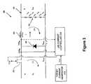
- FIG. 1shows an exemplary switch-mode system 100 .
- Switch-mode system 100includes a switch-mode converter power stage 102 , a converter current controller 104 , and a load 106 .
- Power 101is fed into switch-mode converter power stage 102 .
- Switch-mode system 100utilizes switch-mode converter power stage 102 to convert alternating current (AC) voltages (such as line/mains voltages) to direct current (DC) voltages or DC-to-DC wherein the input current is proportional to the input voltage.
- Converter current-controller 104controls the current of switch-mode converter power-stage 102 , and switch-mode-converter power stage 102 accordingly drives load 106 .
- An exemplary switch-mode converter power stage 102may be a buck converter or a boost converter.
- DCMDiscontinuous Conduction Mode
- CCMContinuous Conduction Mode
- FIG. 2Ashows exemplary target current i target (for inductor current i L ) having a value of three (3) amp.
- FIG. 2Afurther shows inductor current i L has a period of ten (10) microsecond and is always non-zero in value.
- the current swingis less than in DCM, which results in lower I 2 R power losses and lower ripple current for inductor current i L which results in lower inductor core losses.
- the lower voltage swingalso reduces Electro Magnetic Interference (EMI), and a smaller input filter can then be used.
- EMIElectro Magnetic Interference
- the switch of switch-mode converter power stage 102is turned “OFF” when the inductor current i L is not equal to zero, the diode of switch-mode converter power stage 102 needs to be very fast in terms of reverse recovery in order to minimize losses.
- a switch of switch-mode converter power stage 102is turned on (e.g., “ON”) by converter current controller 104 when the inductor current i L of the inductor of switch-mode converter power stage 102 equals zero.
- FIG. 2Bshows exemplary target current i target having a value of 0.8 amp.
- FIG. 2Bfurther shows inductor current i L has a period of ten (10) microsecond and does fall to the zero value at a portion of each period.
- a switch-mode system 100 used to drive a Light Emitting Diode (LED) lighting systemit is important to have an accurate constant current output that is adjustable across a wide dynamic range, such as a range of one hundred-to-one (100:1).
- Such an accurate adjustable constant outputrequires a switch-mode converter power stage 102 that can smoothly transition between CCM and DCM and provide a controlled output in both CCM and DCM.
- the current rippleneeds to be minimized.
- Such low current ripplegenerally calls for operation of the switch-mode converter power stage 102 to be in CCM.
- switch-mode converter power stage 102will operate in DCM at a lower average current i average for inductor current i L . If the current of switch-mode converter power stage 102 in CCM mode is controlled in such a way that the time above target current i target and the time below that target current i target are equal, then the average current i average is equal to the target current i target , assuming linear (non-saturating) operation of the inductor.
- CCM operation of switch-mode converter power stage 102generally does not require knowing the inductor value L (or scaled: inductor constant F*L product wherein F may be an on-time period divided by the count value of the on-time period) nor the input/output ratio D in order to provide such accurate constant average current output.
- the converter systemcomprises a converter power stage that can operate in a Discontinuous Conduction Mode (DCM) in a range of output currents and a Continuous Conduction Mode (CCM) in another range of output currents.
- the converter power stageincludes at least an inductor with an inductor value and a control switch.
- the converter power stageprovides an average current.
- a current controlleris coupled to the converter power stage. When the converter power stage operates in DCM, the converter power stage provides the average current and the current controller is configured to measure the inductor value of the inductor. Furthermore, the current controller can also be configured to measure an input-to-output conversion ratio from the converter power stage.
- FIG. 1depicts an exemplary switch-mode system.
- FIG. 2Adepicts exemplary current waveforms of inductor current i L and target current i target for switch-mode converter 102 operating in Continuous Conduction Mode (“CCM”) shown at a time scale of 10 milliseconds.
- CCMContinuous Conduction Mode
- FIG. 2Bdepicts exemplary current waveforms of inductor current i L and target current i target for switch-mode converter 102 operating in Discontinuous Conduction Mode (“DCM”) shown at a time scale of 10 milliseconds.
- DCMDiscontinuous Conduction Mode
- FIG. 3depicts details of an exemplary switch-mode buck converter power stage controlled by a Light Emitting Diode (“LED”) current controller for driving LEDs.
- LEDLight Emitting Diode
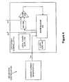
- FIG. 4depicts details of an exemplary LED lighting controller that includes a target current generator and a LED current controller.
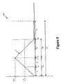
- FIG. 5depicts an exemplary current waveform for inductor current i L of exemplary switch-mode buck converter that is used to illustrate a first exemplary technique to provide an accurate constant average inductor current output when exemplary switch-mode buck converter power stage operates in DCM to help allow for a smooth transition of switch-mode buck converter power stage between CCM and DCM.
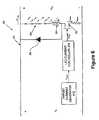
- FIG. 6depicts details of another exemplary switch-mode buck converter power stage controlled by a LED current controller for driving LEDs.
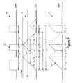
- FIG. 7depicts exemplary current waveforms for control signal CS 0 , inductor current i L , and sense current i sense of exemplary switch-mode buck converter power stage that are used to illustrate second and third exemplary techniques to each provide an accurate constant average inductor current output by exemplary switch-mode buck converter power stage operating in a hybrid Discontinuous Conduction Mode (DCM)/Continuous Conduction Mode (CCM) that uses double or more pulses in a switching period wherein the techniques help allow for a smooth transition of switch-mode buck converter power stage between CCM and DCM.
- DCMDiscontinuous Conduction Mode
- CCMContinuous Conduction Mode
- FIG. 3depicts details of an Light Emitting Diode (“LED”) lighting system 300 having an exemplary switch-mode buck converter power stage 301 controlled by a Light Emitting Diode. (“LED”) current controller 310 for driving LEDs 308 .
- LED lighting system 300is an exemplary system illustrating an embodiment of the present invention, and the present invention is not in any way limited to an LED lighting system nor the use of a buck converter, LED current controller, and LEDs.
- the present inventioncan also be used for other suitable applications as well as utilize other converters/converter power stages (e.g., boost converters) or controllers.
- Switch-mode buck converter power stage 301comprises a control switch (e.g., Field Effect Transistor (“FET”)) 302 having a source and drain coupled in series with an inductor 304 as shown in FIG. 3 .
- the source of FET 302is coupled to a positive side of input voltage V in .
- Diode 306is coupled across the input voltage V in in which a first end of a diode 306 is coupled between the drain of FET 302 and inductor 304 while a second end of diode 306 is coupled to a negative side of the input voltage V in .
- a string of LEDs 308is coupled across the output voltage V out (e.g., coupled from the positive side to negative side of output voltage V out ).
- the string of LEDs 308may, for example, include twenty (20) to one hundred (100) LEDs coupled together in series.
- sense resistor R senseis coupled to the negative side of input voltage V in , and the other end of sense resistor R sense is coupled to the second end of diode 306 .
- Sense resistor R senseis utilized to detect the sense current i sense that is flowing through FET 302 .
- the sense resistor R sensecan be located anywhere in the current loop 312 .
- an end of sense resistor R senseis coupled to the second end of diode 306
- the other end of sense resistor R senseis coupled to the negative side of the output voltage V out .
- the sense resistor R sensecan be located anywhere in the current loop 314 .
- LED current controller 310outputs a switch control signal CS 0 which is fed into the gate of FET 302 and controls activation and deactivation of FET 302 as a switch.
- the output voltage V out of exemplary LED lighting system 300 at full brightness intensitycan be at or around four hundred milliamperes (400 mA).
- Switch-mode buck converter power stage 301operates in CCM when the output voltage V out is at least fifty (50) to one hundred (100) milliamperes (50 to 100 mA).
- switch-mode buck converter power stage 301operates in DCM.
- LED lighting system 300the load inductor current i L is always measurable, that is, the high side switch of FET 302 is measurable.
- a target current generator 412is coupled to the LED current controller 310 for feeding a target current i target into LED current controller 310 .
- Target current generator 412 and LED current controller 310together make up LED lighting controller 400 as shown in FIG. 4 .
- LED current controller 310includes a local power supply 402 which provides power to the various components of LED current controller 310 .
- LED current controller 310further includes a state machine 410 which receives the target current i target that is fed in from target current generator 412 .
- State machine 410provides a digital signal that is reflective or representative of the target current i target to digital-to-analog converter 404 .
- DAC 404converts the representative digital signal into a corresponding analog signal.
- the analog signal and the sense current i senseare fed into comparator (COMP) 406 for comparison, and the result of the comparison is fed into state machine 410 .
- LED current controller 310further includes a clock (oscillator) 408 , and clock (osc) 408 is coupled to and utilized by state machine 410 .
- the techniquese.g., first, second, and third techniques of the present invention in providing an accurate adjustable constant average inductor current output i avg when a converter operates in DCM are implemented in state machine 410 .
- LED controller 310may be implemented on a single integrated circuit (IC) or single IC substrate.
- Target current generator 412may also be part of the single IC or may be external to the IC.
- a reference current i refis set at a suitable value, which is some pre-selected current value between zero and the peak current i peak .
- Reference current i refis set at a value that can be accurately measured but allows the load inductor current i L to ramp up to the peak current i peak as well.
- FIG. 5depicts an exemplary current waveform 500 for inductor current i L of exemplary switch-mode buck converter power stage 301 that is used to illustrate a first exemplary technique to provide an accurate adjustable constant average inductor current output i avg when exemplary switch-mode buck converter operates in DCM.
- First exemplary techniquehelp allow for a smooth transition of switch-mode buck converter power stage between CCM and DCM.
- time period T 1is the time from when FET 302 turns on and when the load inductor i L reaches the reference current i ref .
- the second on time period T 2is determined from when the FET 302 is on at the time when the load inductor i L reaches the reference current i ref (e.g., at time T A ) to when the load inductor i L reaches the peak current i peak (e.g., at time n*T A ).
- nis a ratio and is preferably selected to be a ratio of 2 (e.g., 2:1).
- Load inductor current i Ldecreases in value passing through reference current i ref and falls to zero at time T B .
- the off time period T 3is defined from when the load inductor i L reaches the peak current i peak (e.g., at time n*T A ) until when the load inductor i L reaches zero (e.g., at time T B ).
- the total period for inductor current i L in FIG. 5is defined as time-period TT.
- both the on time T on(which is equal to time periods T 1 +T 2 ) and off time T off (which is equal to time period T 3 ) can be observed or measured, but only the on period T on and total period TT can be controlled. Therefore, in implementing the LED lighting system 300 , either the on period T on or total period TT is controlled in order to provide an accurate constant average current output i avg for inductor current i L .
- the measuring and determination of inductor value (inductance) L for inductor 304is not in any way limited to the measurement and determination of the actual inductance of inductor 304 (e.g., measured in milli-Henries) but can be a measurement or determination of any value that is representative or reflective of the inductance value.
- a representative or reflective valuemay be in conformity with a mathematical rate of increase related to the inductance, a scaled version of the inductance, a binary format of the inductance, or a direct, indirect or inverse proportional relationship to the inductance (e.g., L; 1/L, etc.).
- Ratio C 1provides a relationship in which the inductor value L is determined based on the rate of rise (e.g., i ref /T 1 ) of the current when FET 302 is switched on.
- T onSquare Root(2* i AVG *D/C 1* TT ) Equation G
- on time T on for FET 302can be controlled for providing a given adjustable average constant output inductor current i AVG for inductor current i L by using the measured, determined, and/or known values for the input/output ratio D, the ratio C 1 , and the total period TT of inductor current i L .
- FIG. 6depicts details of another Light Emitting Diode (“LED”) lighting system 600 having another exemplary switch-mode buck converter power stage 601 controlled by a Light Emitting Diode (“LED”) current controller 310 for driving LEDs 308 .
- FIG. 6also shows LED current controller 310 coupled to target current generator 412 , and as mentioned before, when FIG. 4 was discussed earlier, target current generator 412 and LED current controller 310 make up LED lighting controller 400 .
- LED lighting system 600is another exemplary system illustrating another embodiment of the present invention, and the present invention is not in any way limited to an LED lighting system nor the use of a buck converter power stage, LED current controller, and LEDs.
- the present inventioncan also be used for other suitable applications as well as utilize other converters/converter power stages (e.g., boost converters) or controllers.
- Switch-mode buck converter power stage 601comprises LEDs 308 , inductor 304 , FET (control switch) 302 , and sense resistor R sense coupled in series together and across the output voltage V out as shown in FIG. 6 .
- One end of diode 306is coupled to a positive side of input voltage V in , and the other end of diode 306 is coupled at a node between inductor 304 and FET 302 as shown in FIG. 6 .
- Output current i outis shown flowing at the positive side of output voltage V out .
- Inductor current i Lflows through inductor 304 while sense current i sense flows through resistor R sense .
- sense resistor R senseis utilized to detect the sense current i sense that is flowing through FET 302 .
- LED current controller 310outputs a switch control signal CS 0 which is fed into the gate of FET 302 and controls activation and deactivation of FET 302 as a switch.
- Switch-mode buck converter power stage 601can only allow the measuring or detecting of the inductor current i L when FET 302 is on and cannot allow the measuring or detecting of inductor current i L when FET 302 is off.
- switch-mode buck converter power stage 601requires sense current i sense only when FET 302 is on, and the low side switch 302 can be used for sensing sense current i sense .
- exemplary current waveforms 700 , 702 , and 704 for respective control signal CS 0 , inductor current i L , and sense current i sense of exemplary switch-mode buck converter power stage 601that are used to illustrate second and third exemplary techniques to each provide an accurate adjustable constant average inductor current output i avg by exemplary switch-mode buck converter 601 operating in a hybrid Discontinuous Conduction Mode (DCM)/Continuous Conduction Mode (CCM) that uses double or more pulses in a switching period.
- DCMDiscontinuous Conduction Mode
- CCMContinuous Conduction Mode
- Control signal CS 0transitions to a high value and turns on FET 302 during period T 1 .
- Inductor current i Lramps up and crosses through reference current i ref and reaches peak current i peak at the end of period T 1 .
- Sense current i senseramps up to a peak sense current value during time period T 1 .
- control signal CS 0goes to a low value and turns off FET 302 .
- switch-mode buck converter 601cannot allow the detection of the value of inductor current i L , and sense current i sense discharges to a zero value.
- Control signal CS 0next goes back to a high value and turns on FET 302 during time period T 3 .
- Inductor current i Lramps back up and crosses through reference current i ref and reaches peak current i peak again.
- switch-mode buck converter power stage 601can allow the value of inductor current i L to be detected, and sense current i sense ramps up to a peak sense current value.
- Control signal CS 0then goes back to a low vale and turns off FET 302 during time period T 4 .
- Inductor current i Lramps down to zero during time period T 4 .
- switch-mode buck converter power stage 601cannot allow for the detection of the value of inductor current i L , and sense current i sense discharges to a zero value.
- time period T 3is less than time period T 1 , switch-mode buck converter power stage 601 has then entered into the hybrid DCM/CCM that uses double or more pulses in a switching period. However, if time period T 3 is approximately equal to time period T 1 , then time period T 2 needs to be adjusted (e.g., decreased) so that time period T 3 will be less than time period T 1 .
- T 4 /T 1T 2 /T 3 Equation I
- T 4T 1 /T 3 *T 2 Equation J
- the double or more pulses of a switching-period for inductor current i L as shown in current waveform 702is basically an overlap of two single pulses (e.g., each involving time periods T 1 and T 4 only).
- the overlap charge area A 1being a triangular area as shown in current waveform 702 .
- the left side length of the overlap charge area A 1is reflective of the difference between time periods T 1 and T 3 while the right side length of the overlap charge area A 1 is reflective of the difference between time periods T 4 and T 2 .
- ratio C 1as discussed for the first exemplary technique provides the same relationship in which the inductor value L is determined based on the rate of rise (e.g., i ref /T 1 ) of the current when FET 302 for converter 601 is switched on.
- This second exemplary techniquereflects the fact that the FET 302 is turned on again at least for a second time within the switching period TT before inductor current i L decays to zero.
- a third exemplary technique for providing an accurate adjustable constant average inductor current output i avg by exemplary switch-mode buck converter power stage 601is further discussed.
- a single triangular pulse with a known charge area of A 1results since time periods T 1 and T 3 are known, and the single triangular pulse is added in the current waveform 702 for inductor current i L .
- converter power stage 301 or 601When converter power stage 301 or 601 operates in DCM, converter power stage 301 or 601 is able to provide an average constant output current that is adjustably controlled by an inductor value that is measured and/or detected and further controlled by an input-to-output conversion ratio that is measured and/or detected.
- the exemplary techniques of the present inventionallow the inductor value (e.g., inductor value L) and the input-to-output conversion ratio (e.g., input-to-output ratio D) to be accurately measured, determined, or discovered.
Landscapes
- Engineering & Computer Science (AREA)
- Power Engineering (AREA)
- Dc-Dc Converters (AREA)
Abstract
Description
Peak currentipeak=Ton*(Vin−Vout)/L Equation A
Off time periodToff=((Vin−Vout)/Vout)*Ton Equation B
D=Vout/Vin=Ton/(Ton+Toff) Equation C
Reference currentiref=T1*(Vin−Vout)/L Equation D
RatioC1=iref/T1=(Vin−Vout)/L Equation E
Ton=Square Root(2*iAVG*D/C1*TT) Equation G
Total chargeQsingle=Q1+Q2=(T1+T4)*ipeak/2 Equation H
T4/T1=T2/T3 Equation I
T4=T1/T3*T2 Equation J
Total ChargeQT=2*Qsingle−A1 Equation K
Overlap charge areaA1=((T1−T3)/T1)*Q1+((T4−T2)/T4)*Q2)
Total ChargeQT=2*Qsingle−A1+A1=2*Qsingle Equation O
Claims (24)
Priority Applications (4)
| Application Number | Priority Date | Filing Date | Title |
|---|---|---|---|
| US12/242,009US8179110B2 (en) | 2008-09-30 | 2008-09-30 | Adjustable constant current source with continuous conduction mode (“CCM”) and discontinuous conduction mode (“DCM”) operation |
| PCT/US2009/058298WO2010039588A2 (en) | 2008-09-30 | 2009-09-25 | Adjustable constant current source with continuous conduction mode ("ccm") and discontinuous conduction mode ("dcm") operation |
| CN200980147607.XACN102232264B (en) | 2008-09-30 | 2009-09-25 | Adjustable constant current source with continuous conduction mode (CCM) and discontinuous conduction mode (DCM) operation |
| GB1105424.4AGB2475668B (en) | 2008-09-30 | 2009-09-25 | Adjustable constant current source with continuous conduction mode ("CCM") and discontinuous conduction mode ("DCM") operation |
Applications Claiming Priority (1)
| Application Number | Priority Date | Filing Date | Title |
|---|---|---|---|
| US12/242,009US8179110B2 (en) | 2008-09-30 | 2008-09-30 | Adjustable constant current source with continuous conduction mode (“CCM”) and discontinuous conduction mode (“DCM”) operation |
Publications (2)
| Publication Number | Publication Date |
|---|---|
| US20100079124A1 US20100079124A1 (en) | 2010-04-01 |
| US8179110B2true US8179110B2 (en) | 2012-05-15 |
Family
ID=41651473
Family Applications (1)
| Application Number | Title | Priority Date | Filing Date |
|---|---|---|---|
| US12/242,009Expired - Fee RelatedUS8179110B2 (en) | 2008-09-30 | 2008-09-30 | Adjustable constant current source with continuous conduction mode (“CCM”) and discontinuous conduction mode (“DCM”) operation |
Country Status (4)
| Country | Link |
|---|---|
| US (1) | US8179110B2 (en) |
| CN (1) | CN102232264B (en) |
| GB (1) | GB2475668B (en) |
| WO (1) | WO2010039588A2 (en) |
Cited By (18)
| Publication number | Priority date | Publication date | Assignee | Title |
|---|---|---|---|---|
| US20110254458A1 (en)* | 2010-04-20 | 2011-10-20 | Chien-Chih Kuo | Output controllable frequency modulation electronic ballast |
| US20110273157A1 (en)* | 2009-01-13 | 2011-11-10 | Abu-Qahouq Jaber A | Sensor-less operation and detection of ccm and dcm operation modes in synchronous switching power converters |
| US20130300383A1 (en)* | 2012-05-11 | 2013-11-14 | Texas Instruments Incorporated | Current mode control for dc-dc converter |
| US9198247B2 (en)* | 2014-02-12 | 2015-11-24 | Koito Manufacturing Co., Ltd. | Vehicle lamp, driving device thereof, and control method thereof |
| CN105375752A (en)* | 2014-08-12 | 2016-03-02 | 依必安派特穆尔芬根有限两合公司 | System to increase the in-line power factor of a three-phase brushless dc motor |
| US20160081171A1 (en)* | 2014-09-16 | 2016-03-17 | Koito Manufacturing Co., Ltd. | Lighting circuit and vehicle lamp having the same |
| US9313840B2 (en) | 2011-06-03 | 2016-04-12 | Cirrus Logic, Inc. | Control data determination from primary-side sensing of a secondary-side voltage in a switching power converter |
| US9510401B1 (en) | 2010-08-24 | 2016-11-29 | Cirrus Logic, Inc. | Reduced standby power in an electronic power control system |
| US9544955B2 (en) | 2011-12-19 | 2017-01-10 | Tridonic Gmbh & Co Kg | Operating circuit for light emitting diodes and method for operating light emitting diodes |
| US9775205B1 (en) | 2017-02-20 | 2017-09-26 | Nxp B.V. | Discontinuous mode buck converter and method therefor |
| US20170325304A1 (en)* | 2016-05-04 | 2017-11-09 | Delta Electronics (Shanghai) Co., Ltd. | Dimming driver circuit and control method thereof |
| US20180013344A1 (en)* | 2016-07-11 | 2018-01-11 | Infineon Technologies Austria Ag | System and Method for Controlling Current in a Switching Regulator |
| US10123384B1 (en)* | 2017-09-22 | 2018-11-06 | Linear Technology Holding, LLC | LED dimming |
| US10136488B1 (en) | 2017-10-05 | 2018-11-20 | Linear Technology Holding, LLC | LED dimming |
| US10201052B1 (en)* | 2017-09-22 | 2019-02-05 | Linear Technology Holding, LLC | LED dimming |
| US11496060B2 (en) | 2020-11-18 | 2022-11-08 | Power Integrations, Inc. | Pulse sharing control for enhancing performance in a multiple output power converter system |
| US11611279B2 (en) | 2019-04-24 | 2023-03-21 | Power Integrations, Inc. | Input line voltage operation for a power converter |
| US11632054B2 (en) | 2019-04-24 | 2023-04-18 | Power Integrations, Inc. | Mode operation detection for control of a power converter with an active clamp switch |
Families Citing this family (35)
| Publication number | Priority date | Publication date | Assignee | Title |
|---|---|---|---|---|
| US8232742B2 (en) | 2008-11-27 | 2012-07-31 | Arkalumen Inc. | Method, apparatus and computer-readable media for controlling lighting devices |
| US8964413B2 (en)* | 2010-04-22 | 2015-02-24 | Flextronics Ap, Llc | Two stage resonant converter enabling soft-switching in an isolated stage |
| US8564214B2 (en) | 2010-05-11 | 2013-10-22 | Arkalumen Inc. | Circuits for sensing current levels within lighting apparatus |
| US9089024B2 (en) | 2010-05-11 | 2015-07-21 | Arkalumen Inc. | Methods and apparatus for changing a DC supply voltage applied to a lighting circuit |
| US9086435B2 (en) | 2011-05-10 | 2015-07-21 | Arkalumen Inc. | Circuits for sensing current levels within a lighting apparatus incorporating a voltage converter |
| US9192009B2 (en) | 2011-02-14 | 2015-11-17 | Arkalumen Inc. | Lighting apparatus and method for detecting reflected light from local objects |
| US8941308B2 (en) | 2011-03-16 | 2015-01-27 | Arkalumen Inc. | Lighting apparatus and methods for controlling lighting apparatus using ambient light levels |
| US8939604B2 (en) | 2011-03-25 | 2015-01-27 | Arkalumen Inc. | Modular LED strip lighting apparatus |
| WO2012137130A2 (en)* | 2011-04-04 | 2012-10-11 | Sgm A/S | Method for driving leds |
| US9060400B2 (en) | 2011-07-12 | 2015-06-16 | Arkalumen Inc. | Control apparatus incorporating a voltage converter for controlling lighting apparatus |
| JP5960817B2 (en)* | 2011-08-01 | 2016-08-02 | コーニンクレッカ フィリップス エヌ ヴェKoninklijke Philips N.V. | Driver device and driving method for driving load, especially LED unit |
| US8680783B2 (en) | 2011-08-10 | 2014-03-25 | Cree, Inc. | Bias voltage generation using a load in series with a switch |
| EP2573575B1 (en)* | 2011-09-23 | 2016-04-13 | Infineon Technologies AG | Digital switching converter control |
| SG189603A1 (en) | 2011-11-04 | 2013-05-31 | Opulent Electronics Internat Pte Ltd | System for driving a plurality of high powered led units |
| US20140203790A1 (en)* | 2013-01-23 | 2014-07-24 | Fairchild Semiconductor Corporation | Hybrid Continuous and Discontinuous Mode Operation |
| AT14041U1 (en)* | 2013-04-30 | 2015-03-15 | Tridonic Gmbh & Co Kg | Operating circuit for light-emitting diodes with filter element |
| GB2514380A (en)* | 2013-05-22 | 2014-11-26 | Bernard Frederick Fellerman | LED driver circuit |
| TWI524811B (en)* | 2013-08-14 | 2016-03-01 | Richtek Technology Corp | Light emitting diode system and voltage conversion device |
| US9647558B2 (en)* | 2014-05-02 | 2017-05-09 | Intersil Americas LLC | System and method for maintaining a constant output voltage ripple in a buck converter in discontinuous conduction mode |
| CN104619092B (en)* | 2015-02-12 | 2017-03-29 | 辉芒微电子(深圳)有限公司 | A kind of LED drive circuit |
| US10225904B2 (en) | 2015-05-05 | 2019-03-05 | Arkalumen, Inc. | Method and apparatus for controlling a lighting module based on a constant current level from a power source |
| US9992836B2 (en) | 2015-05-05 | 2018-06-05 | Arkawmen Inc. | Method, system and apparatus for activating a lighting module using a buffer load module |
| US9775211B2 (en) | 2015-05-05 | 2017-09-26 | Arkalumen Inc. | Circuit and apparatus for controlling a constant current DC driver output |
| US10568180B2 (en) | 2015-05-05 | 2020-02-18 | Arkalumen Inc. | Method and apparatus for controlling a lighting module having a plurality of LED groups |
| US9992829B2 (en) | 2015-05-05 | 2018-06-05 | Arkalumen Inc. | Control apparatus and system for coupling a lighting module to a constant current DC driver |
| JP6687425B2 (en)* | 2015-07-31 | 2020-04-22 | 株式会社小糸製作所 | Lighting circuit and vehicle lamp using the same |
| FR3039741B1 (en) | 2015-07-31 | 2020-11-27 | Koito Mfg Co Ltd | LIGHTING SYSTEM AND LAMP OF VEHICLE USER |
| TWI607669B (en)* | 2015-11-25 | 2017-12-01 | 凌通科技股份有限公司 | Single battery infrared circuit and remote controller using the same |
| US10405381B2 (en)* | 2016-06-02 | 2019-09-03 | Semiconductor Components Industries, Llc | Light emitting diode control circuit with wide range input voltage |
| US10715045B1 (en) | 2019-01-25 | 2020-07-14 | Semiconductor Components Industries, Llc | Methods and systems of operating power converters |
| US11728731B2 (en)* | 2020-05-09 | 2023-08-15 | Intel Corporation | Accurate load current sensing apparatus and method |
| CN111682764B (en)* | 2020-05-20 | 2021-09-17 | 珠海格力节能环保制冷技术研究中心有限公司 | Automatically-adjustable DC-DC voltage reduction circuit and control method |
| US11811314B2 (en)* | 2020-12-30 | 2023-11-07 | Texas Instruments Incorporated | Multi-mode power converter with programmable control |
| US11706853B2 (en)* | 2021-10-06 | 2023-07-18 | Microsoft Technology Licensing, Llc | Monitoring an emission state of light sources |
| GB2614089B (en)* | 2021-12-21 | 2024-05-29 | Cirrus Logic Int Semiconductor Ltd | Current estimation in a power converter |
Citations (214)
| Publication number | Priority date | Publication date | Assignee | Title |
|---|---|---|---|---|
| US3316495A (en) | 1964-07-06 | 1967-04-25 | Cons Systems Corp | Low-level commutator with means for providing common mode rejection |
| US3423689A (en) | 1965-08-19 | 1969-01-21 | Hewlett Packard Co | Direct current amplifier |
| US3586988A (en) | 1967-12-01 | 1971-06-22 | Newport Lab | Direct coupled differential amplifier |
| US3725804A (en) | 1971-11-26 | 1973-04-03 | Avco Corp | Capacitance compensation circuit for differential amplifier |
| US3790878A (en) | 1971-12-22 | 1974-02-05 | Keithley Instruments | Switching regulator having improved control circuiting |
| US3881167A (en) | 1973-07-05 | 1975-04-29 | Pelton Company Inc | Method and apparatus to maintain constant phase between reference and output signals |
| US4075701A (en) | 1975-02-12 | 1978-02-21 | Messerschmitt-Bolkow-Blohm Gesellschaft Mit Beschrankter Haftung | Method and circuit arrangement for adapting the measuring range of a measuring device operating with delta modulation in a navigation system |
| GB2069269A (en) | 1980-02-11 | 1981-08-19 | Tektronix Inc | Supply voltage driver |
| US4334250A (en) | 1978-03-16 | 1982-06-08 | Tektronix, Inc. | MFM data encoder with write precompensation |
| US4414493A (en) | 1981-10-06 | 1983-11-08 | Thomas Industries Inc. | Light dimmer for solid state ballast |
| US4476706A (en) | 1982-01-18 | 1984-10-16 | Delphian Partners | Remote calibration system |
| US4677366A (en) | 1986-05-12 | 1987-06-30 | Pioneer Research, Inc. | Unity power factor power supply |
| US4683529A (en) | 1986-11-12 | 1987-07-28 | Zytec Corporation | Switching power supply with automatic power factor correction |
| US4700188A (en) | 1985-01-29 | 1987-10-13 | Micronic Interface Technologies | Electric power measurement system and hall effect based electric power meter for use therein |
| US4737658A (en) | 1985-08-05 | 1988-04-12 | Brown, Boveri & Cie Ag | Centralized control receiver |
| US4797633A (en) | 1987-03-20 | 1989-01-10 | Video Sound, Inc. | Audio amplifier |
| US4937728A (en) | 1989-03-07 | 1990-06-26 | Rca Licensing Corporation | Switch-mode power supply with burst mode standby operation |
| US4940929A (en) | 1989-06-23 | 1990-07-10 | Apollo Computer, Inc. | AC to DC converter with unity power factor |
| US4973919A (en) | 1989-03-23 | 1990-11-27 | Doble Engineering Company | Amplifying with directly coupled, cascaded amplifiers |
| US4979087A (en) | 1988-09-09 | 1990-12-18 | Aviation Limited | Inductive coupler |
| US4980898A (en) | 1989-08-08 | 1990-12-25 | Siemens-Pacesetter, Inc. | Self-oscillating burst mode transmitter with integral number of periods |
| US4992919A (en) | 1989-12-29 | 1991-02-12 | Lee Chu Quon | Parallel resonant converter with zero voltage switching |
| US4994952A (en) | 1988-02-10 | 1991-02-19 | Electronics Research Group, Inc. | Low-noise switching power supply having variable reluctance transformer |
| US5001620A (en) | 1988-07-25 | 1991-03-19 | Astec International Limited | Power factor improvement |
| US5109185A (en) | 1989-09-29 | 1992-04-28 | Ball Newton E | Phase-controlled reversible power converter presenting a controllable counter emf to a source of an impressed voltage |
| US5121079A (en) | 1991-02-12 | 1992-06-09 | Dargatz Marvin R | Driven-common electronic amplifier |
| US5206540A (en) | 1991-05-09 | 1993-04-27 | Unitrode Corporation | Transformer isolated drive circuit |
| US5264780A (en) | 1992-08-10 | 1993-11-23 | International Business Machines Corporation | On time control and gain circuit |
| US5278490A (en) | 1990-09-04 | 1994-01-11 | California Institute Of Technology | One-cycle controlled switching circuit |
| EP0585789A1 (en) | 1992-09-01 | 1994-03-09 | Power Integrations, Inc. | Three-terminal switched mode power supply integrated circuit |
| US5323157A (en) | 1993-01-15 | 1994-06-21 | Motorola, Inc. | Sigma-delta digital-to-analog converter with reduced noise |
| US5359180A (en) | 1992-10-02 | 1994-10-25 | General Electric Company | Power supply system for arcjet thrusters |
| US5383109A (en) | 1993-12-10 | 1995-01-17 | University Of Colorado | High power factor boost rectifier apparatus |
| US5424932A (en) | 1993-01-05 | 1995-06-13 | Yokogawa Electric Corporation | Multi-output switching power supply having an improved secondary output circuit |
| US5477481A (en) | 1991-02-15 | 1995-12-19 | Crystal Semiconductor Corporation | Switched-capacitor integrator with chopper stabilization performed at the sampling rate |
| US5479333A (en) | 1994-04-25 | 1995-12-26 | Chrysler Corporation | Power supply start up booster circuit |
| US5481178A (en) | 1993-03-23 | 1996-01-02 | Linear Technology Corporation | Control circuit and method for maintaining high efficiency over broad current ranges in a switching regulator circuit |
| US5565761A (en) | 1994-09-02 | 1996-10-15 | Micro Linear Corp | Synchronous switching cascade connected offline PFC-PWM combination power converter controller |
| US5589759A (en) | 1992-07-30 | 1996-12-31 | Sgs-Thomson Microelectronics S.R.L. | Circuit for detecting voltage variations in relation to a set value, for devices comprising error amplifiers |
| US5638265A (en) | 1993-08-24 | 1997-06-10 | Gabor; George | Low line harmonic AC to DC power supply |
| US5691890A (en) | 1995-12-01 | 1997-11-25 | International Business Machines Corporation | Power supply with power factor correction circuit |
| US5747977A (en) | 1995-03-30 | 1998-05-05 | Micro Linear Corporation | Switching regulator having low power mode responsive to load power consumption |
| US5757635A (en) | 1995-12-28 | 1998-05-26 | Samsung Electronics Co., Ltd. | Power factor correction circuit and circuit therefor having sense-FET and boost converter control circuit |
| US5764039A (en) | 1995-11-15 | 1998-06-09 | Samsung Electronics Co., Ltd. | Power factor correction circuit having indirect input voltage sensing |
| US5781040A (en) | 1996-10-31 | 1998-07-14 | Hewlett-Packard Company | Transformer isolated driver for power transistor using frequency switching as the control signal |
| US5783909A (en) | 1997-01-10 | 1998-07-21 | Relume Corporation | Maintaining LED luminous intensity |
| US5798635A (en) | 1996-06-20 | 1998-08-25 | Micro Linear Corporation | One pin error amplifier and switched soft-start for an eight pin PFC-PWM combination integrated circuit converter controller |
| EP0910168A1 (en) | 1997-10-16 | 1999-04-21 | Hewlett-Packard Company | Delta-sigma pulse width modulator |
| US5900683A (en) | 1997-12-23 | 1999-05-04 | Ford Global Technologies, Inc. | Isolated gate driver for power switching device and method for carrying out same |
| US5929400A (en) | 1997-12-22 | 1999-07-27 | Otis Elevator Company | Self commissioning controller for field-oriented elevator motor/drive system |
| US5946202A (en) | 1997-01-24 | 1999-08-31 | Baker Hughes Incorporated | Boost mode power conversion |
| US5946206A (en) | 1997-02-17 | 1999-08-31 | Tdk Corporation | Plural parallel resonant switching power supplies |
| US5952849A (en) | 1997-02-21 | 1999-09-14 | Analog Devices, Inc. | Logic isolator with high transient immunity |
| US5960207A (en) | 1997-01-21 | 1999-09-28 | Dell Usa, L.P. | System and method for reducing power losses by gating an active power factor conversion process |
| US5963086A (en) | 1997-08-08 | 1999-10-05 | Velodyne Acoustics, Inc. | Class D amplifier with switching control |
| US5966297A (en) | 1997-08-28 | 1999-10-12 | Iwatsu Electric Co., Ltd. | Large bandwidth analog isolation circuit |
| US6016038A (en) | 1997-08-26 | 2000-01-18 | Color Kinetics, Inc. | Multicolored LED lighting method and apparatus |
| US6043633A (en) | 1998-06-05 | 2000-03-28 | Systel Development & Industries | Power factor correction method and apparatus |
| US6072969A (en) | 1996-03-05 | 2000-06-06 | Canon Kabushiki Kaisha | Developing cartridge |
| US6083276A (en) | 1998-06-11 | 2000-07-04 | Corel, Inc. | Creating and configuring component-based applications using a text-based descriptive attribute grammar |
| US6084450A (en) | 1997-01-14 | 2000-07-04 | The Regents Of The University Of California | PWM controller with one cycle response |
| US6181114B1 (en) | 1999-10-26 | 2001-01-30 | International Business Machines Corporation | Boost circuit which includes an additional winding for providing an auxiliary output voltage |
| WO2001015316A1 (en) | 1999-08-23 | 2001-03-01 | Intel Corporation | Method and apparatus for matching common mode output voltage at a switched-capacitor to continuous-time interface |
| US6211626B1 (en) | 1997-08-26 | 2001-04-03 | Color Kinetics, Incorporated | Illumination components |
| US6211627B1 (en) | 1997-07-29 | 2001-04-03 | Michael Callahan | Lighting systems |
| US6229271B1 (en) | 2000-02-24 | 2001-05-08 | Osram Sylvania Inc. | Low distortion line dimmer and dimming ballast |
| US6229292B1 (en) | 1999-02-12 | 2001-05-08 | Analog Devices, Inc. | Voltage regulator compensation circuit and method |
| US6246183B1 (en) | 2000-02-28 | 2001-06-12 | Litton Systems, Inc. | Dimmable electrodeless light source |
| US6259614B1 (en) | 1999-07-12 | 2001-07-10 | International Rectifier Corporation | Power factor correction control circuit |
| US6300723B1 (en) | 1998-07-29 | 2001-10-09 | Philips Electronics North America Corporation | Apparatus for power factor control |
| US6304473B1 (en) | 2000-06-02 | 2001-10-16 | Iwatt | Operating a power converter at optimal efficiency |
| US6343026B1 (en) | 2000-11-09 | 2002-01-29 | Artesyn Technologies, Inc. | Current limit circuit for interleaved converters |
| US6344811B1 (en) | 1999-03-16 | 2002-02-05 | Audio Logic, Inc. | Power supply compensation for noise shaped, digital amplifiers |
| WO2002015386A2 (en) | 2000-08-14 | 2002-02-21 | K.S. Waves Ltd. | High-efficiency audio power amplifier |
| US6385063B1 (en) | 1998-06-23 | 2002-05-07 | Siemens Aktiengesellschaft | Hybrid filter for an alternating current network |
| EP1213823A2 (en) | 2000-12-04 | 2002-06-12 | Sanken Electric Co., Ltd. | DC-to-DC converter |
| US6407691B1 (en) | 2000-10-18 | 2002-06-18 | Cirrus Logic, Inc. | Providing power, clock, and control signals as a single combined signal across an isolation barrier in an ADC |
| US6441558B1 (en) | 2000-12-07 | 2002-08-27 | Koninklijke Philips Electronics N.V. | White LED luminary light control system |
| US6445600B2 (en) | 1998-07-13 | 2002-09-03 | Ben-Gurion University Of The Negev Research & Development Authority | Modular structure of an apparatus for regulating the harmonics of current drawn from power lines by an electronic load |
| US6452521B1 (en) | 2001-03-14 | 2002-09-17 | Rosemount Inc. | Mapping a delta-sigma converter range to a sensor range |
| US20020145041A1 (en) | 2001-03-16 | 2002-10-10 | Koninklijke Philips Electronics N.V. | RGB LED based light driver using microprocessor controlled AC distributed power system |
| US20020150151A1 (en) | 1997-04-22 | 2002-10-17 | Silicon Laboratories Inc. | Digital isolation system with hybrid circuit in ADC calibration loop |
| US6469484B2 (en) | 2000-12-13 | 2002-10-22 | Semiconductor Components Industries Llc | Power supply circuit and method thereof to detect demagnitization of the power supply |
| US20020166073A1 (en) | 2001-05-02 | 2002-11-07 | Nguyen James Hung | Apparatus and method for adaptively controlling power supplied to a hot-pluggable subsystem |
| WO2002091805A2 (en) | 2001-05-10 | 2002-11-14 | Color Kinetics Incorporated | Systems and methods for synchronizing lighting effects |
| US6495964B1 (en) | 1998-12-18 | 2002-12-17 | Koninklijke Philips Electronics N.V. | LED luminaire with electrically adjusted color balance using photodetector |
| US6509913B2 (en) | 1998-04-30 | 2003-01-21 | Openwave Systems Inc. | Configurable man-machine interface |
| US20030095013A1 (en) | 2000-05-10 | 2003-05-22 | Melanson John L. | Modulation of a digital input signal using a digital signal modulator and signal splitting |
| US6583550B2 (en) | 2000-10-24 | 2003-06-24 | Toyoda Gosei Co., Ltd. | Fluorescent tube with light emitting diodes |
| US20030174520A1 (en) | 2000-10-24 | 2003-09-18 | Igor Bimbaud | Self-oscillating control circuit voltage converter |
| US6628106B1 (en) | 2001-07-30 | 2003-09-30 | University Of Central Florida | Control method and circuit to provide voltage and current regulation for multiphase DC/DC converters |
| US6636003B2 (en) | 2000-09-06 | 2003-10-21 | Spectrum Kinetics | Apparatus and method for adjusting the color temperature of white semiconduct or light emitters |
| US6646848B2 (en) | 2001-01-31 | 2003-11-11 | Matsushita Electric Industrial Co., Ltd. | Switching power supply apparatus |
| US20030223255A1 (en) | 2002-05-31 | 2003-12-04 | Green Power Technologies Ltd. | Method and apparatus for active power factor correction with minimum input current distortion |
| US20040004465A1 (en) | 2002-07-08 | 2004-01-08 | Cogency Semiconductor Inc. | Dual-output direct current voltage converter |
| US6688753B2 (en) | 2001-02-02 | 2004-02-10 | Koninklijke Philips Electronics N.V. | Integrated light source |
| US20040046683A1 (en) | 2001-03-08 | 2004-03-11 | Shindengen Electric Manufacturing Co., Ltd. | DC stabilized power supply |
| US6713974B2 (en) | 2002-01-10 | 2004-03-30 | Lightech Electronic Industries Ltd. | Lamp transformer for use with an electronic dimmer and method for use thereof for reducing acoustic noise |
| US6724174B1 (en) | 2002-09-12 | 2004-04-20 | Linear Technology Corp. | Adjustable minimum peak inductor current level for burst mode in current-mode DC-DC regulators |
| US6727832B1 (en) | 2002-11-27 | 2004-04-27 | Cirrus Logic, Inc. | Data converters with digitally filtered pulse width modulation output stages and methods and systems using the same |
| US20040085030A1 (en) | 2002-10-30 | 2004-05-06 | Benoit Laflamme | Multicolor lamp system |
| US20040085117A1 (en) | 2000-12-06 | 2004-05-06 | Joachim Melbert | Method and device for switching on and off power semiconductors, especially for the torque-variable operation of an asynchronous machine, for operating an ignition system for spark ignition engines, and switched-mode power supply |
| US6737845B2 (en) | 2001-06-21 | 2004-05-18 | Champion Microelectronic Corp. | Current inrush limiting and bleed resistor current inhibiting in a switching power converter |
| US6741123B1 (en) | 2002-12-26 | 2004-05-25 | Cirrus Logic, Inc. | Delta-sigma amplifiers with output stage supply voltage variation compensation and methods and digital amplifier systems using the same |
| US6753661B2 (en) | 2002-06-17 | 2004-06-22 | Koninklijke Philips Electronics N.V. | LED-based white-light backlighting for electronic displays |
| US6768655B1 (en) | 2003-02-03 | 2004-07-27 | System General Corp. | Discontinuous mode PFC controller having a power saving modulator and operation method thereof |
| US6781351B2 (en) | 2002-08-17 | 2004-08-24 | Supertex Inc. | AC/DC cascaded power converters having high DC conversion ratio and improved AC line harmonics |
| US20040169477A1 (en) | 2003-02-28 | 2004-09-02 | Naoki Yanai | Dimming-control lighting apparatus for incandescent electric lamp |
| US6788011B2 (en) | 1997-08-26 | 2004-09-07 | Color Kinetics, Incorporated | Multicolored LED lighting method and apparatus |
| US20040228116A1 (en) | 2003-05-13 | 2004-11-18 | Carroll Miller | Electroluminescent illumination for a magnetic compass |
| US20040227571A1 (en) | 2003-05-12 | 2004-11-18 | Yasuji Kuribayashi | Power amplifier circuit |
| US20040232971A1 (en) | 2003-03-06 | 2004-11-25 | Denso Corporation | Electrically insulated switching element drive circuit |
| US20040239262A1 (en) | 2002-05-28 | 2004-12-02 | Shigeru Ido | Electronic ballast for a discharge lamp |
| US6839247B1 (en) | 2003-07-10 | 2005-01-04 | System General Corp. | PFC-PWM controller having a power saving means |
| US6860628B2 (en) | 2002-07-17 | 2005-03-01 | Jonas J. Robertson | LED replacement for fluorescent lighting |
| US20050057237A1 (en) | 2002-01-11 | 2005-03-17 | Robert Clavel | Power factor controller |
| US6870325B2 (en) | 2002-02-22 | 2005-03-22 | Oxley Developments Company Limited | Led drive circuit and method |
| US6873065B2 (en) | 1997-10-23 | 2005-03-29 | Analog Devices, Inc. | Non-optical signal isolator |
| US6882552B2 (en) | 2000-06-02 | 2005-04-19 | Iwatt, Inc. | Power converter driven by power pulse and sense pulse |
| US6888322B2 (en) | 1997-08-26 | 2005-05-03 | Color Kinetics Incorporated | Systems and methods for color changing device and enclosure |
| US6894471B2 (en) | 2002-05-31 | 2005-05-17 | St Microelectronics S.R.L. | Method of regulating the supply voltage of a load and related voltage regulator |
| US20050156770A1 (en) | 2004-01-16 | 2005-07-21 | Melanson John L. | Jointly nonlinear delta sigma modulators |
| US20050168492A1 (en) | 2002-05-28 | 2005-08-04 | Koninklijke Philips Electronics N.V. | Motion blur decrease in varying duty cycle |
| US6933706B2 (en) | 2003-09-15 | 2005-08-23 | Semiconductor Components Industries, Llc | Method and circuit for optimizing power efficiency in a DC-DC converter |
| US20050184895A1 (en) | 2004-02-25 | 2005-08-25 | Nellcor Puritan Bennett Inc. | Multi-bit ADC with sigma-delta modulation |
| US6940733B2 (en) | 2002-08-22 | 2005-09-06 | Supertex, Inc. | Optimal control of wide conversion ratio switching converters |
| US6944034B1 (en) | 2003-06-30 | 2005-09-13 | Iwatt Inc. | System and method for input current shaping in a power converter |
| US20050207190A1 (en) | 2004-03-22 | 2005-09-22 | Gritter David J | Power system having a phase locked loop with a notch filter |
| US20050218838A1 (en) | 2004-03-15 | 2005-10-06 | Color Kinetics Incorporated | LED-based lighting network power control methods and apparatus |
| US6956750B1 (en) | 2003-05-16 | 2005-10-18 | Iwatt Inc. | Power converter controller having event generator for detection of events and generation of digital error |
| US6958920B2 (en) | 2003-10-02 | 2005-10-25 | Supertex, Inc. | Switching power converter and method of controlling output voltage thereof using predictive sensing of magnetic flux |
| US20050253533A1 (en) | 2002-05-09 | 2005-11-17 | Color Kinetics Incorporated | Dimmable LED-based MR16 lighting apparatus methods |
| US6967448B2 (en) | 1997-08-26 | 2005-11-22 | Color Kinetics, Incorporated | Methods and apparatus for controlling illumination |
| US6970503B1 (en) | 2000-04-21 | 2005-11-29 | National Semiconductor Corporation | Apparatus and method for converting analog signal to pulse-width-modulated signal |
| US20050270813A1 (en) | 2004-06-04 | 2005-12-08 | Wanfeng Zhang | Parallel current mode control |
| US6975079B2 (en) | 1997-08-26 | 2005-12-13 | Color Kinetics Incorporated | Systems and methods for controlling illumination sources |
| US6975523B2 (en) | 2002-10-16 | 2005-12-13 | Samsung Electronics Co., Ltd. | Power supply capable of protecting electric device circuit |
| US20050275386A1 (en) | 2002-06-23 | 2005-12-15 | Powerlynx A/S | Power converter |
| US20050275354A1 (en) | 2004-06-10 | 2005-12-15 | Hausman Donald F Jr | Apparatus and methods for regulating delivery of electrical energy |
| US6980446B2 (en) | 2002-02-08 | 2005-12-27 | Sanken Electric Co., Ltd. | Circuit for starting power source apparatus |
| US20060023002A1 (en) | 2004-08-02 | 2006-02-02 | Oki Electric Industry Co., Ltd. | Color balancing circuit for a display panel |
| US20060022916A1 (en) | 2004-06-14 | 2006-02-02 | Natale Aiello | LED driving device with variable light intensity |
| EP1014563B1 (en) | 1998-12-14 | 2006-03-01 | Alcatel | Amplifier arrangement with voltage gain and reduced power consumption |
| US7034611B2 (en) | 2004-02-09 | 2006-04-25 | Texas Instruments Inc. | Multistage common mode feedback for improved linearity line drivers |
| US20060125420A1 (en) | 2004-12-06 | 2006-06-15 | Michael Boone | Candle emulation device |
| US7064498B2 (en) | 1997-08-26 | 2006-06-20 | Color Kinetics Incorporated | Light-emitting diode based products |
| US7064531B1 (en) | 2005-03-31 | 2006-06-20 | Micrel, Inc. | PWM buck regulator with LDO standby mode |
| US7075329B2 (en) | 2003-04-30 | 2006-07-11 | Analog Devices, Inc. | Signal isolators using micro-transformers |
| US7078963B1 (en) | 2003-03-21 | 2006-07-18 | D2Audio Corporation | Integrated PULSHI mode with shutdown |
| US7088059B2 (en) | 2004-07-21 | 2006-08-08 | Boca Flasher | Modulated control circuit and method for current-limited dimming and color mixing of display and illumination systems |
| US7102902B1 (en) | 2005-02-17 | 2006-09-05 | Ledtronics, Inc. | Dimmer circuit for LED |
| US7106603B1 (en) | 2005-05-23 | 2006-09-12 | Li Shin International Enterprise Corporation | Switch-mode self-coupling auxiliary power device |
| US7109791B1 (en) | 2004-07-09 | 2006-09-19 | Rf Micro Devices, Inc. | Tailored collector voltage to minimize variation in AM to PM distortion in a power amplifier |
| US20060214603A1 (en) | 2005-03-22 | 2006-09-28 | In-Hwan Oh | Single-stage digital power converter for driving LEDs |
| US20060226795A1 (en) | 2005-04-08 | 2006-10-12 | S.C. Johnson & Son, Inc. | Lighting device having a circuit including a plurality of light emitting diodes, and methods of controlling and calibrating lighting devices |
| US7126288B2 (en) | 2003-05-05 | 2006-10-24 | International Rectifier Corporation | Digital electronic ballast control apparatus and method |
| US20060238136A1 (en) | 2003-07-02 | 2006-10-26 | Johnson Iii H F | Lamp and bulb for illumination and ambiance lighting |
| US20060261754A1 (en) | 2005-05-18 | 2006-11-23 | Samsung Electro-Mechanics Co., Ltd. | LED driving circuit having dimming circuit |
| US7145295B1 (en) | 2005-07-24 | 2006-12-05 | Aimtron Technology Corp. | Dimming control circuit for light-emitting diodes |
| US20060285365A1 (en) | 2005-06-16 | 2006-12-21 | Active Semiconductors International Inc. | Primary side constant output current controller |
| WO2006135584A1 (en) | 2005-06-10 | 2006-12-21 | Rf Micro Devices, Inc. | Doherty amplifier configuration for a collector controlled power amplifier |
| US7158633B1 (en) | 1999-11-16 | 2007-01-02 | Silicon Laboratories, Inc. | Method and apparatus for monitoring subscriber loop interface circuitry power dissipation |
| US20070024213A1 (en) | 2005-07-28 | 2007-02-01 | Synditec, Inc. | Pulsed current averaging controller with amplitude modulation and time division multiplexing for arrays of independent pluralities of light emitting diodes |
| US20070029946A1 (en) | 2005-08-03 | 2007-02-08 | Yu Chung-Che | APPARATUS OF LIGHT SOURCE AND ADJUSTABLE CONTROL CIRCUIT FOR LEDs |
| US20070040512A1 (en) | 2005-08-17 | 2007-02-22 | Tir Systems Ltd. | Digitally controlled luminaire system |
| US7183957B1 (en) | 2005-12-30 | 2007-02-27 | Cirrus Logic, Inc. | Signal processing system with analog-to-digital converter using delta-sigma modulation having an internal stabilizer loop |
| US20070053182A1 (en) | 2005-09-07 | 2007-03-08 | Jonas Robertson | Combination fluorescent and LED lighting system |
| US20070103949A1 (en) | 2004-08-27 | 2007-05-10 | Sanken Electric Co., Ltd. | Power factor improving circuit |
| US7221130B2 (en) | 2005-01-05 | 2007-05-22 | Fyrestorm, Inc. | Switching power converter employing pulse frequency modulation control |
| US20070124615A1 (en) | 2005-11-29 | 2007-05-31 | Potentia Semiconductor Corporation | Standby arrangement for power supplies |
| US7233135B2 (en) | 2003-09-29 | 2007-06-19 | Murata Manufacturing Co., Ltd. | Ripple converter |
| US7246919B2 (en) | 2004-03-03 | 2007-07-24 | S.C. Johnson & Son, Inc. | LED light bulb with active ingredient emission |
| US20070182699A1 (en) | 2006-02-09 | 2007-08-09 | Samsung Electro-Mechanics Co., Ltd. | Field sequential color mode liquid crystal display |
| US7255457B2 (en) | 1999-11-18 | 2007-08-14 | Color Kinetics Incorporated | Methods and apparatus for generating and modulating illumination conditions |
| US7266001B1 (en) | 2004-03-19 | 2007-09-04 | Marvell International Ltd. | Method and apparatus for controlling power factor correction |
| US7288902B1 (en) | 2007-03-12 | 2007-10-30 | Cirrus Logic, Inc. | Color variations in a dimmable lighting device with stable color temperature light sources |
| US7292013B1 (en) | 2004-09-24 | 2007-11-06 | Marvell International Ltd. | Circuits, systems, methods, and software for power factor correction and/or control |
| WO2007141741A1 (en)* | 2006-06-08 | 2007-12-13 | Koninklijke Philips Electronics N.V. | Circuitry for dimming led illumination devices |
| US7310244B2 (en) | 2006-01-25 | 2007-12-18 | System General Corp. | Primary side controlled switching regulator |
| US7317305B1 (en)* | 2005-05-18 | 2008-01-08 | Volterra Semiconductor Corporation | Method and apparatus for multi-phase DC-DC converters using coupled inductors in discontinuous conduction mode |
| US7323828B2 (en)* | 2005-04-25 | 2008-01-29 | Catalyst Semiconductor, Inc. | LED current bias control using a step down regulator |
| US20080043504A1 (en) | 2006-08-16 | 2008-02-21 | On-Bright Electronics (Shanghai) Co., Ltd. | System and method for providing control for switch-mode power supply |
| US20080054815A1 (en) | 2006-09-01 | 2008-03-06 | Broadcom Corporation | Single inductor serial-parallel LED driver |
| US7345458B2 (en) | 2003-07-07 | 2008-03-18 | Nippon Telegraph And Telephone Corporation | Booster that utilizes energy output from a power supply unit |
| US20080130322A1 (en) | 2006-12-01 | 2008-06-05 | Artusi Daniel A | Power system with power converters having an adaptive controller |
| US7394210B2 (en) | 2004-09-29 | 2008-07-01 | Tir Technology Lp | System and method for controlling luminaires |
| US20080175029A1 (en) | 2007-01-18 | 2008-07-24 | Sang-Hwa Jung | Burst mode operation in a DC-DC converter |
| US20080174291A1 (en) | 2002-04-29 | 2008-07-24 | Emerson Energy Systems Ab | Power Supply System and Apparatus |
| US20080174372A1 (en) | 2007-01-19 | 2008-07-24 | Tucker John C | Multi-stage amplifier with multiple sets of fixed and variable voltage rails |
| US20080192509A1 (en) | 2007-02-13 | 2008-08-14 | Dhuyvetter Timothy A | Dc-dc converter with isolation |
| US20080224635A1 (en) | 2004-12-20 | 2008-09-18 | Outside In (Cambridge) Limited | Lighting Apparatus and Method |
| US20080232141A1 (en) | 2006-12-01 | 2008-09-25 | Artusi Daniel A | Power System with Power Converters Having an Adaptive Controller |
| US20080239764A1 (en) | 2007-03-30 | 2008-10-02 | Cambridge Semiconductor Limited | Forward power converter controllers |
| US20080259655A1 (en) | 2007-04-19 | 2008-10-23 | Da-Chun Wei | Switching-mode power converter and pulse-width-modulation control circuit with primary-side feedback control |
| US20080278132A1 (en) | 2007-05-07 | 2008-11-13 | Kesterson John W | Digital Compensation For Cable Drop In A Primary Side Control Power Supply Controller |
| US7511437B2 (en) | 2006-02-10 | 2009-03-31 | Philips Solid-State Lighting Solutions, Inc. | Methods and apparatus for high power factor controlled power delivery using a single switching stage per load |
| US7518350B2 (en)* | 2005-12-16 | 2009-04-14 | Silicon Laboratories Inc. | MCU/driver point of load digital controller with optimized voltage |
| US7538499B2 (en) | 2005-03-03 | 2009-05-26 | Tir Technology Lp | Method and apparatus for controlling thermal stress in lighting devices |
| US7545130B2 (en) | 2005-11-11 | 2009-06-09 | L&L Engineering, Llc | Non-linear controller for switching power supply |
| US20090147544A1 (en) | 2007-12-11 | 2009-06-11 | Melanson John L | Modulated transformer-coupled gate control signaling method and apparatus |
| US7554473B2 (en) | 2007-05-02 | 2009-06-30 | Cirrus Logic, Inc. | Control system using a nonlinear delta-sigma modulator with nonlinear process modeling |
| US20090174479A1 (en) | 2008-01-04 | 2009-07-09 | Texas Instruments Incorporated | High-voltage differential amplifier and method using low voltage amplifier and dynamic voltage selection |
| US7569996B2 (en) | 2004-03-19 | 2009-08-04 | Fred H Holmes | Omni voltage direct current power supply |
| US7583136B2 (en) | 2000-03-28 | 2009-09-01 | International Rectifier Corporation | Active filter for reduction of common mode current |
| US20090218960A1 (en) | 2007-03-13 | 2009-09-03 | Renaissance Lighting, Inc. | Step-wise intensity control of a solid state lighting system |
| US7652459B2 (en)* | 2007-02-23 | 2010-01-26 | Intel Corporation | Adaptive controller with mode tracking and parametric estimation for digital power converters |
| US7656103B2 (en) | 2006-01-20 | 2010-02-02 | Exclara, Inc. | Impedance matching circuit for current regulation of solid state lighting |
| US7710047B2 (en) | 2004-09-21 | 2010-05-04 | Exclara, Inc. | System and method for driving LED |
| US7746671B2 (en) | 2005-05-23 | 2010-06-29 | Infineon Technologies Ag | Control circuit for a switch unit of a clocked power supply circuit, and resonance converter |
| US7750738B2 (en) | 2008-11-20 | 2010-07-06 | Infineon Technologies Ag | Process, voltage and temperature control for high-speed, low-power fixed and variable gain amplifiers based on MOSFET resistors |
| EP2204905A1 (en) | 2008-12-31 | 2010-07-07 | Cirrus Logic, Inc. | Electronic system having common mode voltage range enhancement |
| US7759881B1 (en)* | 2008-03-31 | 2010-07-20 | Cirrus Logic, Inc. | LED lighting system with a multiple mode current control dimming strategy |
| US7804256B2 (en) | 2007-03-12 | 2010-09-28 | Cirrus Logic, Inc. | Power control system for current regulated light sources |
| US7855864B2 (en)* | 2005-03-31 | 2010-12-21 | Semtech Corporation | Switched mode power supply method and apparatus |
Family Cites Families (3)
| Publication number | Priority date | Publication date | Assignee | Title |
|---|---|---|---|---|
| JP4060840B2 (en)* | 2004-10-01 | 2008-03-12 | 松下電器産業株式会社 | Light emitting diode driving semiconductor circuit and light emitting diode driving device having the same |
| US7598682B2 (en)* | 2006-05-26 | 2009-10-06 | Nexxus Lighting, Inc. | Current regulator apparatus and methods |
| US7902771B2 (en)* | 2006-11-21 | 2011-03-08 | Exclara, Inc. | Time division modulation with average current regulation for independent control of arrays of light emitting diodes |
- 2008
- 2008-09-30USUS12/242,009patent/US8179110B2/ennot_activeExpired - Fee Related
- 2009
- 2009-09-25CNCN200980147607.XApatent/CN102232264B/ennot_activeExpired - Fee Related
- 2009-09-25WOPCT/US2009/058298patent/WO2010039588A2/enactiveApplication Filing
- 2009-09-25GBGB1105424.4Apatent/GB2475668B/ennot_activeExpired - Fee Related
Patent Citations (231)
| Publication number | Priority date | Publication date | Assignee | Title |
|---|---|---|---|---|
| US3316495A (en) | 1964-07-06 | 1967-04-25 | Cons Systems Corp | Low-level commutator with means for providing common mode rejection |
| US3423689A (en) | 1965-08-19 | 1969-01-21 | Hewlett Packard Co | Direct current amplifier |
| US3586988A (en) | 1967-12-01 | 1971-06-22 | Newport Lab | Direct coupled differential amplifier |
| US3725804A (en) | 1971-11-26 | 1973-04-03 | Avco Corp | Capacitance compensation circuit for differential amplifier |
| US3790878A (en) | 1971-12-22 | 1974-02-05 | Keithley Instruments | Switching regulator having improved control circuiting |
| US3881167A (en) | 1973-07-05 | 1975-04-29 | Pelton Company Inc | Method and apparatus to maintain constant phase between reference and output signals |
| US4075701A (en) | 1975-02-12 | 1978-02-21 | Messerschmitt-Bolkow-Blohm Gesellschaft Mit Beschrankter Haftung | Method and circuit arrangement for adapting the measuring range of a measuring device operating with delta modulation in a navigation system |
| US4334250A (en) | 1978-03-16 | 1982-06-08 | Tektronix, Inc. | MFM data encoder with write precompensation |
| GB2069269A (en) | 1980-02-11 | 1981-08-19 | Tektronix Inc | Supply voltage driver |
| US4414493A (en) | 1981-10-06 | 1983-11-08 | Thomas Industries Inc. | Light dimmer for solid state ballast |
| US4476706A (en) | 1982-01-18 | 1984-10-16 | Delphian Partners | Remote calibration system |
| US4700188A (en) | 1985-01-29 | 1987-10-13 | Micronic Interface Technologies | Electric power measurement system and hall effect based electric power meter for use therein |
| US4737658A (en) | 1985-08-05 | 1988-04-12 | Brown, Boveri & Cie Ag | Centralized control receiver |
| US4677366A (en) | 1986-05-12 | 1987-06-30 | Pioneer Research, Inc. | Unity power factor power supply |
| US4683529A (en) | 1986-11-12 | 1987-07-28 | Zytec Corporation | Switching power supply with automatic power factor correction |
| US4797633A (en) | 1987-03-20 | 1989-01-10 | Video Sound, Inc. | Audio amplifier |
| US4994952A (en) | 1988-02-10 | 1991-02-19 | Electronics Research Group, Inc. | Low-noise switching power supply having variable reluctance transformer |
| US5001620A (en) | 1988-07-25 | 1991-03-19 | Astec International Limited | Power factor improvement |
| US4979087A (en) | 1988-09-09 | 1990-12-18 | Aviation Limited | Inductive coupler |
| US4937728A (en) | 1989-03-07 | 1990-06-26 | Rca Licensing Corporation | Switch-mode power supply with burst mode standby operation |
| US4973919A (en) | 1989-03-23 | 1990-11-27 | Doble Engineering Company | Amplifying with directly coupled, cascaded amplifiers |
| US4940929A (en) | 1989-06-23 | 1990-07-10 | Apollo Computer, Inc. | AC to DC converter with unity power factor |
| US4980898A (en) | 1989-08-08 | 1990-12-25 | Siemens-Pacesetter, Inc. | Self-oscillating burst mode transmitter with integral number of periods |
| US5109185A (en) | 1989-09-29 | 1992-04-28 | Ball Newton E | Phase-controlled reversible power converter presenting a controllable counter emf to a source of an impressed voltage |
| US4992919A (en) | 1989-12-29 | 1991-02-12 | Lee Chu Quon | Parallel resonant converter with zero voltage switching |
| US5278490A (en) | 1990-09-04 | 1994-01-11 | California Institute Of Technology | One-cycle controlled switching circuit |
| US5121079A (en) | 1991-02-12 | 1992-06-09 | Dargatz Marvin R | Driven-common electronic amplifier |
| US5477481A (en) | 1991-02-15 | 1995-12-19 | Crystal Semiconductor Corporation | Switched-capacitor integrator with chopper stabilization performed at the sampling rate |
| US5206540A (en) | 1991-05-09 | 1993-04-27 | Unitrode Corporation | Transformer isolated drive circuit |
| US5589759A (en) | 1992-07-30 | 1996-12-31 | Sgs-Thomson Microelectronics S.R.L. | Circuit for detecting voltage variations in relation to a set value, for devices comprising error amplifiers |
| US5264780A (en) | 1992-08-10 | 1993-11-23 | International Business Machines Corporation | On time control and gain circuit |
| EP0585789A1 (en) | 1992-09-01 | 1994-03-09 | Power Integrations, Inc. | Three-terminal switched mode power supply integrated circuit |
| US5359180A (en) | 1992-10-02 | 1994-10-25 | General Electric Company | Power supply system for arcjet thrusters |
| US5424932A (en) | 1993-01-05 | 1995-06-13 | Yokogawa Electric Corporation | Multi-output switching power supply having an improved secondary output circuit |
| US5323157A (en) | 1993-01-15 | 1994-06-21 | Motorola, Inc. | Sigma-delta digital-to-analog converter with reduced noise |
| US5994885A (en) | 1993-03-23 | 1999-11-30 | Linear Technology Corporation | Control circuit and method for maintaining high efficiency over broad current ranges in a switching regulator circuit |
| US5481178A (en) | 1993-03-23 | 1996-01-02 | Linear Technology Corporation | Control circuit and method for maintaining high efficiency over broad current ranges in a switching regulator circuit |
| US6304066B1 (en) | 1993-03-23 | 2001-10-16 | Linear Technology Corporation | Control circuit and method for maintaining high efficiency over broad current ranges in a switching regular circuit |
| US6580258B2 (en) | 1993-03-23 | 2003-06-17 | Linear Technology Corporation | Control circuit and method for maintaining high efficiency over broad current ranges in a switching regulator circuit |
| US5638265A (en) | 1993-08-24 | 1997-06-10 | Gabor; George | Low line harmonic AC to DC power supply |
| US5383109A (en) | 1993-12-10 | 1995-01-17 | University Of Colorado | High power factor boost rectifier apparatus |
| US5479333A (en) | 1994-04-25 | 1995-12-26 | Chrysler Corporation | Power supply start up booster circuit |
| US5565761A (en) | 1994-09-02 | 1996-10-15 | Micro Linear Corp | Synchronous switching cascade connected offline PFC-PWM combination power converter controller |
| US5747977A (en) | 1995-03-30 | 1998-05-05 | Micro Linear Corporation | Switching regulator having low power mode responsive to load power consumption |
| US5764039A (en) | 1995-11-15 | 1998-06-09 | Samsung Electronics Co., Ltd. | Power factor correction circuit having indirect input voltage sensing |
| US5691890A (en) | 1995-12-01 | 1997-11-25 | International Business Machines Corporation | Power supply with power factor correction circuit |
| US5757635A (en) | 1995-12-28 | 1998-05-26 | Samsung Electronics Co., Ltd. | Power factor correction circuit and circuit therefor having sense-FET and boost converter control circuit |
| US6072969A (en) | 1996-03-05 | 2000-06-06 | Canon Kabushiki Kaisha | Developing cartridge |
| US5798635A (en) | 1996-06-20 | 1998-08-25 | Micro Linear Corporation | One pin error amplifier and switched soft-start for an eight pin PFC-PWM combination integrated circuit converter controller |
| US5781040A (en) | 1996-10-31 | 1998-07-14 | Hewlett-Packard Company | Transformer isolated driver for power transistor using frequency switching as the control signal |
| US5783909A (en) | 1997-01-10 | 1998-07-21 | Relume Corporation | Maintaining LED luminous intensity |
| US6084450A (en) | 1997-01-14 | 2000-07-04 | The Regents Of The University Of California | PWM controller with one cycle response |
| US5960207A (en) | 1997-01-21 | 1999-09-28 | Dell Usa, L.P. | System and method for reducing power losses by gating an active power factor conversion process |
| US5946202A (en) | 1997-01-24 | 1999-08-31 | Baker Hughes Incorporated | Boost mode power conversion |
| US5946206A (en) | 1997-02-17 | 1999-08-31 | Tdk Corporation | Plural parallel resonant switching power supplies |
| US5952849A (en) | 1997-02-21 | 1999-09-14 | Analog Devices, Inc. | Logic isolator with high transient immunity |
| US7050509B2 (en) | 1997-04-22 | 2006-05-23 | Silicon Laboratories Inc. | Digital isolation system with hybrid circuit in ADC calibration loop |
| US20020150151A1 (en) | 1997-04-22 | 2002-10-17 | Silicon Laboratories Inc. | Digital isolation system with hybrid circuit in ADC calibration loop |
| US7003023B2 (en) | 1997-04-22 | 2006-02-21 | Silicon Laboratories Inc. | Digital isolation system with ADC offset calibration |
| US6211627B1 (en) | 1997-07-29 | 2001-04-03 | Michael Callahan | Lighting systems |
| US5963086A (en) | 1997-08-08 | 1999-10-05 | Velodyne Acoustics, Inc. | Class D amplifier with switching control |
| US6806659B1 (en) | 1997-08-26 | 2004-10-19 | Color Kinetics, Incorporated | Multicolored LED lighting method and apparatus |
| US6975079B2 (en) | 1997-08-26 | 2005-12-13 | Color Kinetics Incorporated | Systems and methods for controlling illumination sources |
| US7135824B2 (en) | 1997-08-26 | 2006-11-14 | Color Kinetics Incorporated | Systems and methods for controlling illumination sources |
| US7064498B2 (en) | 1997-08-26 | 2006-06-20 | Color Kinetics Incorporated | Light-emitting diode based products |
| US6211626B1 (en) | 1997-08-26 | 2001-04-03 | Color Kinetics, Incorporated | Illumination components |
| US6016038A (en) | 1997-08-26 | 2000-01-18 | Color Kinetics, Inc. | Multicolored LED lighting method and apparatus |
| US6788011B2 (en) | 1997-08-26 | 2004-09-07 | Color Kinetics, Incorporated | Multicolored LED lighting method and apparatus |
| US6888322B2 (en) | 1997-08-26 | 2005-05-03 | Color Kinetics Incorporated | Systems and methods for color changing device and enclosure |
| US6150774A (en) | 1997-08-26 | 2000-11-21 | Color Kinetics, Incorporated | Multicolored LED lighting method and apparatus |
| US6967448B2 (en) | 1997-08-26 | 2005-11-22 | Color Kinetics, Incorporated | Methods and apparatus for controlling illumination |
| US5966297A (en) | 1997-08-28 | 1999-10-12 | Iwatsu Electric Co., Ltd. | Large bandwidth analog isolation circuit |
| EP0910168A1 (en) | 1997-10-16 | 1999-04-21 | Hewlett-Packard Company | Delta-sigma pulse width modulator |
| US6873065B2 (en) | 1997-10-23 | 2005-03-29 | Analog Devices, Inc. | Non-optical signal isolator |
| US5929400A (en) | 1997-12-22 | 1999-07-27 | Otis Elevator Company | Self commissioning controller for field-oriented elevator motor/drive system |
| US5900683A (en) | 1997-12-23 | 1999-05-04 | Ford Global Technologies, Inc. | Isolated gate driver for power switching device and method for carrying out same |
| US6509913B2 (en) | 1998-04-30 | 2003-01-21 | Openwave Systems Inc. | Configurable man-machine interface |
| US6043633A (en) | 1998-06-05 | 2000-03-28 | Systel Development & Industries | Power factor correction method and apparatus |
| US6083276A (en) | 1998-06-11 | 2000-07-04 | Corel, Inc. | Creating and configuring component-based applications using a text-based descriptive attribute grammar |
| US6385063B1 (en) | 1998-06-23 | 2002-05-07 | Siemens Aktiengesellschaft | Hybrid filter for an alternating current network |
| US6445600B2 (en) | 1998-07-13 | 2002-09-03 | Ben-Gurion University Of The Negev Research & Development Authority | Modular structure of an apparatus for regulating the harmonics of current drawn from power lines by an electronic load |
| US6300723B1 (en) | 1998-07-29 | 2001-10-09 | Philips Electronics North America Corporation | Apparatus for power factor control |
| EP1014563B1 (en) | 1998-12-14 | 2006-03-01 | Alcatel | Amplifier arrangement with voltage gain and reduced power consumption |
| US6495964B1 (en) | 1998-12-18 | 2002-12-17 | Koninklijke Philips Electronics N.V. | LED luminaire with electrically adjusted color balance using photodetector |
| US6229292B1 (en) | 1999-02-12 | 2001-05-08 | Analog Devices, Inc. | Voltage regulator compensation circuit and method |
| US6344811B1 (en) | 1999-03-16 | 2002-02-05 | Audio Logic, Inc. | Power supply compensation for noise shaped, digital amplifiers |
| US6259614B1 (en) | 1999-07-12 | 2001-07-10 | International Rectifier Corporation | Power factor correction control circuit |
| WO2001015316A1 (en) | 1999-08-23 | 2001-03-01 | Intel Corporation | Method and apparatus for matching common mode output voltage at a switched-capacitor to continuous-time interface |
| US6181114B1 (en) | 1999-10-26 | 2001-01-30 | International Business Machines Corporation | Boost circuit which includes an additional winding for providing an auxiliary output voltage |
| US7158633B1 (en) | 1999-11-16 | 2007-01-02 | Silicon Laboratories, Inc. | Method and apparatus for monitoring subscriber loop interface circuitry power dissipation |
| US7255457B2 (en) | 1999-11-18 | 2007-08-14 | Color Kinetics Incorporated | Methods and apparatus for generating and modulating illumination conditions |
| US6229271B1 (en) | 2000-02-24 | 2001-05-08 | Osram Sylvania Inc. | Low distortion line dimmer and dimming ballast |
| US6246183B1 (en) | 2000-02-28 | 2001-06-12 | Litton Systems, Inc. | Dimmable electrodeless light source |
| US7583136B2 (en) | 2000-03-28 | 2009-09-01 | International Rectifier Corporation | Active filter for reduction of common mode current |
| US6970503B1 (en) | 2000-04-21 | 2005-11-29 | National Semiconductor Corporation | Apparatus and method for converting analog signal to pulse-width-modulated signal |
| US20030095013A1 (en) | 2000-05-10 | 2003-05-22 | Melanson John L. | Modulation of a digital input signal using a digital signal modulator and signal splitting |
| US6304473B1 (en) | 2000-06-02 | 2001-10-16 | Iwatt | Operating a power converter at optimal efficiency |
| US6882552B2 (en) | 2000-06-02 | 2005-04-19 | Iwatt, Inc. | Power converter driven by power pulse and sense pulse |
| WO2002015386A2 (en) | 2000-08-14 | 2002-02-21 | K.S. Waves Ltd. | High-efficiency audio power amplifier |
| US6636003B2 (en) | 2000-09-06 | 2003-10-21 | Spectrum Kinetics | Apparatus and method for adjusting the color temperature of white semiconduct or light emitters |
| US6407691B1 (en) | 2000-10-18 | 2002-06-18 | Cirrus Logic, Inc. | Providing power, clock, and control signals as a single combined signal across an isolation barrier in an ADC |
| US6963496B2 (en) | 2000-10-24 | 2005-11-08 | Stmicroelectronics S.A. | Voltage converter with a self-oscillating control circuit |
| US6583550B2 (en) | 2000-10-24 | 2003-06-24 | Toyoda Gosei Co., Ltd. | Fluorescent tube with light emitting diodes |
| US20030174520A1 (en) | 2000-10-24 | 2003-09-18 | Igor Bimbaud | Self-oscillating control circuit voltage converter |
| US6343026B1 (en) | 2000-11-09 | 2002-01-29 | Artesyn Technologies, Inc. | Current limit circuit for interleaved converters |
| EP1213823A2 (en) | 2000-12-04 | 2002-06-12 | Sanken Electric Co., Ltd. | DC-to-DC converter |
| US20040085117A1 (en) | 2000-12-06 | 2004-05-06 | Joachim Melbert | Method and device for switching on and off power semiconductors, especially for the torque-variable operation of an asynchronous machine, for operating an ignition system for spark ignition engines, and switched-mode power supply |
| US6441558B1 (en) | 2000-12-07 | 2002-08-27 | Koninklijke Philips Electronics N.V. | White LED luminary light control system |
| US6469484B2 (en) | 2000-12-13 | 2002-10-22 | Semiconductor Components Industries Llc | Power supply circuit and method thereof to detect demagnitization of the power supply |
| US6646848B2 (en) | 2001-01-31 | 2003-11-11 | Matsushita Electric Industrial Co., Ltd. | Switching power supply apparatus |
| US6688753B2 (en) | 2001-02-02 | 2004-02-10 | Koninklijke Philips Electronics N.V. | Integrated light source |
| US20040046683A1 (en) | 2001-03-08 | 2004-03-11 | Shindengen Electric Manufacturing Co., Ltd. | DC stabilized power supply |
| US6452521B1 (en) | 2001-03-14 | 2002-09-17 | Rosemount Inc. | Mapping a delta-sigma converter range to a sensor range |
| US20020145041A1 (en) | 2001-03-16 | 2002-10-10 | Koninklijke Philips Electronics N.V. | RGB LED based light driver using microprocessor controlled AC distributed power system |
| US20020166073A1 (en) | 2001-05-02 | 2002-11-07 | Nguyen James Hung | Apparatus and method for adaptively controlling power supplied to a hot-pluggable subsystem |
| WO2002091805A2 (en) | 2001-05-10 | 2002-11-14 | Color Kinetics Incorporated | Systems and methods for synchronizing lighting effects |
| US6737845B2 (en) | 2001-06-21 | 2004-05-18 | Champion Microelectronic Corp. | Current inrush limiting and bleed resistor current inhibiting in a switching power converter |
| US6628106B1 (en) | 2001-07-30 | 2003-09-30 | University Of Central Florida | Control method and circuit to provide voltage and current regulation for multiphase DC/DC converters |
| US6713974B2 (en) | 2002-01-10 | 2004-03-30 | Lightech Electronic Industries Ltd. | Lamp transformer for use with an electronic dimmer and method for use thereof for reducing acoustic noise |
| US20050057237A1 (en) | 2002-01-11 | 2005-03-17 | Robert Clavel | Power factor controller |
| US6980446B2 (en) | 2002-02-08 | 2005-12-27 | Sanken Electric Co., Ltd. | Circuit for starting power source apparatus |
| US6870325B2 (en) | 2002-02-22 | 2005-03-22 | Oxley Developments Company Limited | Led drive circuit and method |
| US20080174291A1 (en) | 2002-04-29 | 2008-07-24 | Emerson Energy Systems Ab | Power Supply System and Apparatus |
| US20050253533A1 (en) | 2002-05-09 | 2005-11-17 | Color Kinetics Incorporated | Dimmable LED-based MR16 lighting apparatus methods |
| US20040239262A1 (en) | 2002-05-28 | 2004-12-02 | Shigeru Ido | Electronic ballast for a discharge lamp |
| US20050168492A1 (en) | 2002-05-28 | 2005-08-04 | Koninklijke Philips Electronics N.V. | Motion blur decrease in varying duty cycle |
| US20030223255A1 (en) | 2002-05-31 | 2003-12-04 | Green Power Technologies Ltd. | Method and apparatus for active power factor correction with minimum input current distortion |
| US6894471B2 (en) | 2002-05-31 | 2005-05-17 | St Microelectronics S.R.L. | Method of regulating the supply voltage of a load and related voltage regulator |
| US6753661B2 (en) | 2002-06-17 | 2004-06-22 | Koninklijke Philips Electronics N.V. | LED-based white-light backlighting for electronic displays |
| US20050275386A1 (en) | 2002-06-23 | 2005-12-15 | Powerlynx A/S | Power converter |
| US6756772B2 (en) | 2002-07-08 | 2004-06-29 | Cogency Semiconductor Inc. | Dual-output direct current voltage converter |
| US20040004465A1 (en) | 2002-07-08 | 2004-01-08 | Cogency Semiconductor Inc. | Dual-output direct current voltage converter |
| US6860628B2 (en) | 2002-07-17 | 2005-03-01 | Jonas J. Robertson | LED replacement for fluorescent lighting |
| US6781351B2 (en) | 2002-08-17 | 2004-08-24 | Supertex Inc. | AC/DC cascaded power converters having high DC conversion ratio and improved AC line harmonics |
| US6940733B2 (en) | 2002-08-22 | 2005-09-06 | Supertex, Inc. | Optimal control of wide conversion ratio switching converters |
| US6724174B1 (en) | 2002-09-12 | 2004-04-20 | Linear Technology Corp. | Adjustable minimum peak inductor current level for burst mode in current-mode DC-DC regulators |
| US6975523B2 (en) | 2002-10-16 | 2005-12-13 | Samsung Electronics Co., Ltd. | Power supply capable of protecting electric device circuit |
| US20040085030A1 (en) | 2002-10-30 | 2004-05-06 | Benoit Laflamme | Multicolor lamp system |
| US6727832B1 (en) | 2002-11-27 | 2004-04-27 | Cirrus Logic, Inc. | Data converters with digitally filtered pulse width modulation output stages and methods and systems using the same |
| US6741123B1 (en) | 2002-12-26 | 2004-05-25 | Cirrus Logic, Inc. | Delta-sigma amplifiers with output stage supply voltage variation compensation and methods and digital amplifier systems using the same |
| US6768655B1 (en) | 2003-02-03 | 2004-07-27 | System General Corp. | Discontinuous mode PFC controller having a power saving modulator and operation method thereof |
| US20040169477A1 (en) | 2003-02-28 | 2004-09-02 | Naoki Yanai | Dimming-control lighting apparatus for incandescent electric lamp |
| US20040232971A1 (en) | 2003-03-06 | 2004-11-25 | Denso Corporation | Electrically insulated switching element drive circuit |
| US7078963B1 (en) | 2003-03-21 | 2006-07-18 | D2Audio Corporation | Integrated PULSHI mode with shutdown |
| US7075329B2 (en) | 2003-04-30 | 2006-07-11 | Analog Devices, Inc. | Signal isolators using micro-transformers |
| US7126288B2 (en) | 2003-05-05 | 2006-10-24 | International Rectifier Corporation | Digital electronic ballast control apparatus and method |
| US20040227571A1 (en) | 2003-05-12 | 2004-11-18 | Yasuji Kuribayashi | Power amplifier circuit |
| US20040228116A1 (en) | 2003-05-13 | 2004-11-18 | Carroll Miller | Electroluminescent illumination for a magnetic compass |
| US6956750B1 (en) | 2003-05-16 | 2005-10-18 | Iwatt Inc. | Power converter controller having event generator for detection of events and generation of digital error |
| US6944034B1 (en) | 2003-06-30 | 2005-09-13 | Iwatt Inc. | System and method for input current shaping in a power converter |
| US7161816B2 (en) | 2003-06-30 | 2007-01-09 | Iwatt Inc. | System and method for input current shaping in a power converter |
| US20060238136A1 (en) | 2003-07-02 | 2006-10-26 | Johnson Iii H F | Lamp and bulb for illumination and ambiance lighting |
| US7345458B2 (en) | 2003-07-07 | 2008-03-18 | Nippon Telegraph And Telephone Corporation | Booster that utilizes energy output from a power supply unit |
| US6839247B1 (en) | 2003-07-10 | 2005-01-04 | System General Corp. | PFC-PWM controller having a power saving means |
| US6933706B2 (en) | 2003-09-15 | 2005-08-23 | Semiconductor Components Industries, Llc | Method and circuit for optimizing power efficiency in a DC-DC converter |
| US7233135B2 (en) | 2003-09-29 | 2007-06-19 | Murata Manufacturing Co., Ltd. | Ripple converter |
| US6958920B2 (en) | 2003-10-02 | 2005-10-25 | Supertex, Inc. | Switching power converter and method of controlling output voltage thereof using predictive sensing of magnetic flux |
| US20050156770A1 (en) | 2004-01-16 | 2005-07-21 | Melanson John L. | Jointly nonlinear delta sigma modulators |
| US7034611B2 (en) | 2004-02-09 | 2006-04-25 | Texas Instruments Inc. | Multistage common mode feedback for improved linearity line drivers |
| US20050184895A1 (en) | 2004-02-25 | 2005-08-25 | Nellcor Puritan Bennett Inc. | Multi-bit ADC with sigma-delta modulation |
| US7246919B2 (en) | 2004-03-03 | 2007-07-24 | S.C. Johnson & Son, Inc. | LED light bulb with active ingredient emission |
| US20050218838A1 (en) | 2004-03-15 | 2005-10-06 | Color Kinetics Incorporated | LED-based lighting network power control methods and apparatus |
| US20080012502A1 (en) | 2004-03-15 | 2008-01-17 | Color Kinetics Incorporated | Led power control methods and apparatus |
| US7266001B1 (en) | 2004-03-19 | 2007-09-04 | Marvell International Ltd. | Method and apparatus for controlling power factor correction |
| US7569996B2 (en) | 2004-03-19 | 2009-08-04 | Fred H Holmes | Omni voltage direct current power supply |
| US20050207190A1 (en) | 2004-03-22 | 2005-09-22 | Gritter David J | Power system having a phase locked loop with a notch filter |
| US20050270813A1 (en) | 2004-06-04 | 2005-12-08 | Wanfeng Zhang | Parallel current mode control |
| US20050275354A1 (en) | 2004-06-10 | 2005-12-15 | Hausman Donald F Jr | Apparatus and methods for regulating delivery of electrical energy |
| US20060022916A1 (en) | 2004-06-14 | 2006-02-02 | Natale Aiello | LED driving device with variable light intensity |
| US7109791B1 (en) | 2004-07-09 | 2006-09-19 | Rf Micro Devices, Inc. | Tailored collector voltage to minimize variation in AM to PM distortion in a power amplifier |
| US7088059B2 (en) | 2004-07-21 | 2006-08-08 | Boca Flasher | Modulated control circuit and method for current-limited dimming and color mixing of display and illumination systems |
| US20060023002A1 (en) | 2004-08-02 | 2006-02-02 | Oki Electric Industry Co., Ltd. | Color balancing circuit for a display panel |
| US20070103949A1 (en) | 2004-08-27 | 2007-05-10 | Sanken Electric Co., Ltd. | Power factor improving circuit |
| US7710047B2 (en) | 2004-09-21 | 2010-05-04 | Exclara, Inc. | System and method for driving LED |
| US7292013B1 (en) | 2004-09-24 | 2007-11-06 | Marvell International Ltd. | Circuits, systems, methods, and software for power factor correction and/or control |
| US7394210B2 (en) | 2004-09-29 | 2008-07-01 | Tir Technology Lp | System and method for controlling luminaires |
| US20060125420A1 (en) | 2004-12-06 | 2006-06-15 | Michael Boone | Candle emulation device |
| US20080224635A1 (en) | 2004-12-20 | 2008-09-18 | Outside In (Cambridge) Limited | Lighting Apparatus and Method |
| US7221130B2 (en) | 2005-01-05 | 2007-05-22 | Fyrestorm, Inc. | Switching power converter employing pulse frequency modulation control |
| US7102902B1 (en) | 2005-02-17 | 2006-09-05 | Ledtronics, Inc. | Dimmer circuit for LED |
| US7538499B2 (en) | 2005-03-03 | 2009-05-26 | Tir Technology Lp | Method and apparatus for controlling thermal stress in lighting devices |
| US20060214603A1 (en) | 2005-03-22 | 2006-09-28 | In-Hwan Oh | Single-stage digital power converter for driving LEDs |
| US7855864B2 (en)* | 2005-03-31 | 2010-12-21 | Semtech Corporation | Switched mode power supply method and apparatus |
| US7064531B1 (en) | 2005-03-31 | 2006-06-20 | Micrel, Inc. | PWM buck regulator with LDO standby mode |
| US7375476B2 (en) | 2005-04-08 | 2008-05-20 | S.C. Johnson & Son, Inc. | Lighting device having a circuit including a plurality of light emitting diodes, and methods of controlling and calibrating lighting devices |
| US20060226795A1 (en) | 2005-04-08 | 2006-10-12 | S.C. Johnson & Son, Inc. | Lighting device having a circuit including a plurality of light emitting diodes, and methods of controlling and calibrating lighting devices |
| US7323828B2 (en)* | 2005-04-25 | 2008-01-29 | Catalyst Semiconductor, Inc. | LED current bias control using a step down regulator |
| US20060261754A1 (en) | 2005-05-18 | 2006-11-23 | Samsung Electro-Mechanics Co., Ltd. | LED driving circuit having dimming circuit |
| US7317305B1 (en)* | 2005-05-18 | 2008-01-08 | Volterra Semiconductor Corporation | Method and apparatus for multi-phase DC-DC converters using coupled inductors in discontinuous conduction mode |
| US7106603B1 (en) | 2005-05-23 | 2006-09-12 | Li Shin International Enterprise Corporation | Switch-mode self-coupling auxiliary power device |
| US7746671B2 (en) | 2005-05-23 | 2010-06-29 | Infineon Technologies Ag | Control circuit for a switch unit of a clocked power supply circuit, and resonance converter |
| WO2006135584A1 (en) | 2005-06-10 | 2006-12-21 | Rf Micro Devices, Inc. | Doherty amplifier configuration for a collector controlled power amplifier |
| US7388764B2 (en) | 2005-06-16 | 2008-06-17 | Active-Semi International, Inc. | Primary side constant output current controller |
| US20060285365A1 (en) | 2005-06-16 | 2006-12-21 | Active Semiconductors International Inc. | Primary side constant output current controller |
| US7145295B1 (en) | 2005-07-24 | 2006-12-05 | Aimtron Technology Corp. | Dimming control circuit for light-emitting diodes |
| US20070024213A1 (en) | 2005-07-28 | 2007-02-01 | Synditec, Inc. | Pulsed current averaging controller with amplitude modulation and time division multiplexing for arrays of independent pluralities of light emitting diodes |
| US20070029946A1 (en) | 2005-08-03 | 2007-02-08 | Yu Chung-Che | APPARATUS OF LIGHT SOURCE AND ADJUSTABLE CONTROL CIRCUIT FOR LEDs |
| US20070040512A1 (en) | 2005-08-17 | 2007-02-22 | Tir Systems Ltd. | Digitally controlled luminaire system |
| US20070053182A1 (en) | 2005-09-07 | 2007-03-08 | Jonas Robertson | Combination fluorescent and LED lighting system |
| US7545130B2 (en) | 2005-11-11 | 2009-06-09 | L&L Engineering, Llc | Non-linear controller for switching power supply |
| US20070124615A1 (en) | 2005-11-29 | 2007-05-31 | Potentia Semiconductor Corporation | Standby arrangement for power supplies |
| US7518350B2 (en)* | 2005-12-16 | 2009-04-14 | Silicon Laboratories Inc. | MCU/driver point of load digital controller with optimized voltage |
| US7183957B1 (en) | 2005-12-30 | 2007-02-27 | Cirrus Logic, Inc. | Signal processing system with analog-to-digital converter using delta-sigma modulation having an internal stabilizer loop |
| US7656103B2 (en) | 2006-01-20 | 2010-02-02 | Exclara, Inc. | Impedance matching circuit for current regulation of solid state lighting |
| US7310244B2 (en) | 2006-01-25 | 2007-12-18 | System General Corp. | Primary side controlled switching regulator |
| US20070182699A1 (en) | 2006-02-09 | 2007-08-09 | Samsung Electro-Mechanics Co., Ltd. | Field sequential color mode liquid crystal display |
| US7511437B2 (en) | 2006-02-10 | 2009-03-31 | Philips Solid-State Lighting Solutions, Inc. | Methods and apparatus for high power factor controlled power delivery using a single switching stage per load |
| WO2007141741A1 (en)* | 2006-06-08 | 2007-12-13 | Koninklijke Philips Electronics N.V. | Circuitry for dimming led illumination devices |
| US20090067204A1 (en) | 2006-08-16 | 2009-03-12 | On-Bright Electronics (Shanghai ) Co., Ltd. | System and method for providing control for switch-mode power supply |
| US20080043504A1 (en) | 2006-08-16 | 2008-02-21 | On-Bright Electronics (Shanghai) Co., Ltd. | System and method for providing control for switch-mode power supply |
| US20080054815A1 (en) | 2006-09-01 | 2008-03-06 | Broadcom Corporation | Single inductor serial-parallel LED driver |
| US20080232141A1 (en) | 2006-12-01 | 2008-09-25 | Artusi Daniel A | Power System with Power Converters Having an Adaptive Controller |
| US20080130322A1 (en) | 2006-12-01 | 2008-06-05 | Artusi Daniel A | Power system with power converters having an adaptive controller |
| US20080175029A1 (en) | 2007-01-18 | 2008-07-24 | Sang-Hwa Jung | Burst mode operation in a DC-DC converter |
| US20080174372A1 (en) | 2007-01-19 | 2008-07-24 | Tucker John C | Multi-stage amplifier with multiple sets of fixed and variable voltage rails |
| US20080192509A1 (en) | 2007-02-13 | 2008-08-14 | Dhuyvetter Timothy A | Dc-dc converter with isolation |
| US7652459B2 (en)* | 2007-02-23 | 2010-01-26 | Intel Corporation | Adaptive controller with mode tracking and parametric estimation for digital power converters |
| US7288902B1 (en) | 2007-03-12 | 2007-10-30 | Cirrus Logic, Inc. | Color variations in a dimmable lighting device with stable color temperature light sources |
| US7804256B2 (en) | 2007-03-12 | 2010-09-28 | Cirrus Logic, Inc. | Power control system for current regulated light sources |
| US20090218960A1 (en) | 2007-03-13 | 2009-09-03 | Renaissance Lighting, Inc. | Step-wise intensity control of a solid state lighting system |
| US20080239764A1 (en) | 2007-03-30 | 2008-10-02 | Cambridge Semiconductor Limited | Forward power converter controllers |
| US20080259655A1 (en) | 2007-04-19 | 2008-10-23 | Da-Chun Wei | Switching-mode power converter and pulse-width-modulation control circuit with primary-side feedback control |
| US7719248B1 (en) | 2007-05-02 | 2010-05-18 | Cirrus Logic, Inc. | Discontinuous conduction mode (DCM) using sensed current for a switch-mode converter |
| US7554473B2 (en) | 2007-05-02 | 2009-06-30 | Cirrus Logic, Inc. | Control system using a nonlinear delta-sigma modulator with nonlinear process modeling |
| US7746043B2 (en) | 2007-05-02 | 2010-06-29 | Cirrus Logic, Inc. | Inductor flyback detection using switch gate change characteristic detection |
| US20080278132A1 (en) | 2007-05-07 | 2008-11-13 | Kesterson John W | Digital Compensation For Cable Drop In A Primary Side Control Power Supply Controller |
| US20090147544A1 (en) | 2007-12-11 | 2009-06-11 | Melanson John L | Modulated transformer-coupled gate control signaling method and apparatus |
| US20090174479A1 (en) | 2008-01-04 | 2009-07-09 | Texas Instruments Incorporated | High-voltage differential amplifier and method using low voltage amplifier and dynamic voltage selection |
| US7759881B1 (en)* | 2008-03-31 | 2010-07-20 | Cirrus Logic, Inc. | LED lighting system with a multiple mode current control dimming strategy |
| US7750738B2 (en) | 2008-11-20 | 2010-07-06 | Infineon Technologies Ag | Process, voltage and temperature control for high-speed, low-power fixed and variable gain amplifiers based on MOSFET resistors |
| EP2204905A1 (en) | 2008-12-31 | 2010-07-07 | Cirrus Logic, Inc. | Electronic system having common mode voltage range enhancement |
Non-Patent Citations (166)
| Title |
|---|
| "HV9931 Unity Power Factor LED Lamp Driver, Initial Release", Supertex Inc., Sunnyvale, CA USA 2005. |
| A. Prodic, Compensator Design and Stability Assessment for Fast Voltage Loops of Power Factor Correction Rectifiers, IEEE Transactions on Power Electronics, vol. 22, No. 5, Sep. 2007. |
| A. R. Seidel et al., A Practical Comparison Among High-Power-Factor Electronic Ballasts with Similar Ideas, IEEE Transactions on Industry Applications, vol. 41, No. 6, Nov.-Dec. 2005. |
| A. Silva De Morais et al., A High Power Factor Ballast Using a Single Switch with Both Power Stages Integrated, IEEE Transactions on Power Electronics, vol. 21, No. 2, Mar. 2006. |
| Allegro Microsystems, A1442, "Low Voltage Full Bridge Brushless DC Motor Driver with Hall Commutation and Soft-Switching, and Reverse Battery, Short Circuit, and Thermal Shutdown Protection," Worcester MA, 2009. |
| Analog Devices, "120 kHz Bandwidth, Low Distortion, Isolation Amplifier", AD215, Norwood, MA, 1996. |
| An-H52 Application Note: "HV9931 Unity Power Factor LED Lamp Driver" Mar. 7, 2007, Supertex Inc., Sunnyvale, CA, USA. |
| Azoteq, IQS17 Family, IQ Switch®—ProxSense™ Series, Touch Sensor, Load Control and User Interface, IQS17 Datasheet V2.00.doc, Jan. 2007. |
| B.A. Miwa et al., High Efficiency Power Factor Correction Using Interleaved Techniques, Applied Power Electronics Conference and Exposition, Seventh Annual Conference Proceedings, Feb. 23-27, 1992. |
| Balogh, Laszlo, "Design and Application Guide for High Speed MOSFET Gate Drive Circuits" [Online] 2001, Texas Instruments, Inc., SEM-1400, Unitrode Power Supply Design Seminar, Topic II, TI literature No. SLUP133, XP002552367, Retrieved from the Internet: URL:htt/://focus.ti.com/lit/ml/slup169/slup169.pdf the whole document. |
| Ben-Yaakov et al, "The Dynamics of a PWM Boost Converter with Resistive Input" IEEE Transactions on Industrial Electronics, IEEE Service Center, Piscataway, NJ, USA, vol. 46, No. 3, Jun. 1, 1999. |
| Burr-Brown, ISO120 and ISO121, "Precision Los Cost Isolation Amplifier," Tucson AZ, Mar. 1992. |
| Burr-Brown, ISO130, "High IMR, Low Cost Isolation Amplifier," SBOS220, US, Oct. 2001. |
| C. Dilouie, Introducing the LED Driver, EC&M, Sep. 2004. |
| C. M. De Oliviera Stein et al., A ZCT Auxiliary Communication Circuit for Interleaved Boost Converters Operating in Critical Conduction Mode, IEEE Transactions on Power Electronics, vol. 17, No. 6, Nov. 2002. |
| Chromacity Shifts in High-Power White LED Systems due to Different Dimming Methods, Solid-State Lighting, http://www.lrc.rpi.edu/programs/solidstate/completedProjects.asp?ID=76, printed May 3, 2007. |
| Color Temperature, www.sizes.com/units/color—temperature.htm, printed Mar. 27, 2007. |
| D. Hausman, Lutron, RTISS-TE Operation, Real-Time Illumination Stability Systems for Trailing-Edge (Reverse Phase Control) Dimmers, v. 1.0 Dec. 2004. |
| D. Hausman, Real-Time Illumination Stability Systems for Trailing-Edge (Reverse Phase Control) Dimmers, Technical White Paper, Lutron, version 1.0, Dec. 2004, http://www.lutron.com/technical—info/pdf/RTISS-TE.pdf. |
| D. Maksimovic et al., "Switching Converters with Wide DC Conversion Range," Institute of Electrical and Electronic Engineer's (IEEE) Transactions on Power Electronics, Jan. 1991. |
| D. Rand et al., Issues, Models and Solutions for Triac Modulated Phase Dimming of LED Lamps, Power Electronics Specialists Conference, 2007. |
| D.K.W. Cheng et al., A New Improved Boost Converter with Ripple Free Input Current Using Coupled Inductors, Power Electronics and Variable Speed Drives, Sep. 21-23, 1998. |
| Dallas Semiconductor, Maxim, "Charge-Pump and Step-Up DC-DC Converter Solutions for Powering White LEDs in Series or Parallel Connections," Apr. 23, 2002. |
| Data Sheet LT3496 Triple Output LED Driver, Linear Technology Corporation, Milpitas, CA 2007. |
| Dustin Rand et al: "Issues, Models and Solutions for Triac Modulated Phase Dimming of LED Lamps" Power Electronics Specialists Conferrence, 2007. PESC 2007. IEEE, IEEE, P1, Jun. 1, 2007, pp. 1398-1404. |
| Erickson, Robert W. et al, "Fundamentals of Power Electronics," Second Edition, Chapter 6, Boulder, CO, 2001. |
| F. T. Wakabayashi et al., An Improved Design Procedure for LCC Resonant Filter of Dimmable Electronic Ballasts for Fluorescent Lamps, Based on Lamp Model, IEEE Transactions on Power Electronics, vol. 20, No. 2, Sep. 2005. |
| F. Tao et al., "Single-Stage Power-Factor-Correction Electronic Ballast with a Wide Continuous Dimming Control for Fluorescent Lamps," IEEE Power Electronics Specialists Conference, vol. 2, 2001. |
| Fairchild Semiconductor, Application Note 42030, Theory and Application of the ML4821 Average Current Mode PFC Controller, Oct. 25, 2000. |
| Fairchild Semiconductor, Application Note 42030, Theory and Application of the ML4821 Average Currrent Mode PFC Controller, Aug. 1997. |
| Fairchild Semiconductor, Application Note 42047 Power Factor Correction (PFC) Basics, Rev. 0.9.0 Aug. 19, 2004. |
| Fairchild Semiconductor, Application Note 6004, 500W Power-Factor-Corrected (PFC) Converter Design with FAN4810, Rev. 1.0.1, Oct. 31, 2003. |
| Fairchild Semiconductor, Application Note AN4121, Design of Power Factor Correction Circuit Using FAN7527B, Rev.1.0.1, May 30, 2002. |
| Fairchild Semiconductor, FAN4800, Low Start-up Current PFC/PWM Controller Combos, Nov. 2006. |
| Fairchild Semiconductor, FAN4810, Power Factor Correction Controller, Sep. 24, 2003. |
| Fairchild Semiconductor, FAN4822, ZVA Average Current PFC Controller, Rev. 1.0.1 Aug. 10, 2001. |
| Fairchild Semiconductor, FAN4822, ZVS Average Current PFC Controller, Aug. 10, 2001. |
| Fairchild Semiconductor, FAN7527B, Power Factor Correction Controller, 2003. |
| Fairchild Semiconductor, FAN7532, Ballast Controller, Rev. 1.0.2, Jun. 2006. |
| Fairchild Semiconductor, FAN7544, Simple Ballast Controller, Rev. 1.0.0, 2004. |
| Fairchild Semiconductor, FAN7711, Ballast Control IC, Rev. 1.0.2, Mar. 2007. |
| Fairchild Semiconductor, KA7541, Simple Ballast Controller, Rev. 1.0.3, 2001. |
| Fairchild Semiconductor, ML4812, Power Factor Controller, Rev. 1.0.4, May 31, 2001. |
| Fairchild Semiconductor, ML4821, Power Factor Controller, Jun. 19, 2001. |
| Fairchild Semiconductor, ML4821, Power Factor Controller, Rev. 1.0.2, Jun. 19, 2001. |
| Freescale Semiconductor, AN1965, Design of Indirect Power Factor Correction Using 56F8001E, Jul. 2005. |
| Freescale Semiconductor, AN3052, Implementing PFC Average Current Mode Control Using the MC9S12E128, Nov. 2005. |
| Freescale Semiconductor, Inc., Dimmable Light Ballast with Power Factor Correction, Design Reference Manual, DRM067, Rev. 1, Dec. 2005. |
| G. Yao et al., Soft Switching Circuit for Interleaved Boost Converters, IEEE Transactions on Power Electronics, vol. 22, No. 1, Jan. 2007. |
| H. L. Cheng et al., A Novel Single-Stage High-Power-Factor Electronic Ballast with Symmetrical Topology, IEEE Transactions on Power Electronics, vol. 50, No. 4, Aug. 2003. |
| H. Peng et al., Modeling of Quantization Effects in Digitally Controlled DC-DC Converters, IEEE Transactions on Power Electronics, vol. 22, No. 1, Jan. 2007. |
| H. Wu et al., Single Phase Three-Level Power Factor Correction Circuit with Passive Lossless Snubber, IEEE Transactions on Power Electronics, vol. 17, No. 2, Mar. 2006. |
| Hirota, Atsushi et al, "Analysis of Single Switch Delta-Sigma Modulated Pulse Space Modulation PFC Converter Effectively Using Switching Power Device," IEEE, US, 2002. |
| http://toolbarpdf.com/docs/functions-and-features-of-inverters.html printed on Jan. 20, 2011. |
| Infineon, CCM-PFC Standalone Power Factor Correction (PFC) Controller in Continuous Conduction Mode (CCM), Version 2.1, Feb. 6, 2007. |
| International Rectifier, Application Note AN-1077,PFC Converter Design with IR1150 One Cycle Control IC, rev. 2.3, Jun. 2005. |
| International Rectifier, Data Sheet No. PD60143-O, Current Sensing Single Channel Driver, El Segundo, CA, dated Sep. 8, 2004. |
| International Rectifier, Data Sheet No. PD60230 revC, IR1150(S)(PbF), uPFC One Cycle Control PFC IC Feb. 5, 2007. |
| International Rectifier, Data Sheet PD60230 revC, Feb. 5, 2007. |
| International Rectifier, IRAC1150-300W Demo Board, User's Guide, Rev 3.0, Aug. 2, 2005. |
| International Search Report and Written Opinion for PCT/US2008/062384 dated Jan. 14, 2008. |
| International Search Report and Written Opinion, PCT US20080062378, dated Feb. 5, 2008. |
| International Search Report and Written Opinion, PCT US20080062387, dated Feb. 5, 2008. |
| International Search Report and Written Opinion, PCT US200900032358, dated Jan. 29, 2009. |
| International Search Report and Written Opinion, PCT US20090032351, dated Jan. 29, 2009. |
| International Search Report and Written Report PCT US20080062428 dated Feb. 5, 2008. |
| International Search Report for PCT/US2008/051072, mailed Jun. 4, 2008 |
| International Search Report PCT/GB2005/050228 dated Mar. 14, 2006. |
| International Search Report PCT/GB2006/003259 dated Jan. 12, 2007. |
| International Search Report PCT/US2008/056606 dated Dec. 3, 2008. |
| International Search Report PCT/US2008/056608 dated Dec. 3, 2008. |
| International Search Report PCT/US2008/056739 dated Dec. 3, 2008. |
| International Search Report PCT/US2008/062381 dated Feb. 5, 2008. |
| International Search Report PCT/US2008/062387 dated Jan. 10, 2008. |
| International Search Report PCT/US2008/062398 dated Feb. 5, 2008. |
| J. A. Vilela Jr. et al., An Electronic Ballast with High Power Factor and Low Voltage Stress, IEEE Transactions on Industry Applications, vol. 41, No. 4, Jul./Aug. 2005. |
| J. Qian et al., Charge Pump Power-Factor-Correction Technologies Part II: Ballast Applications, IEEE Transactions on Power Electronics, vol. 15, No. 1, Jan. 2000. |
| J. Qian et al., New Charge Pump Power-Factor-Correction Electronic Ballast with a Wide Range of Line Input Voltage, IEEE Transactions on Power Electronics, vol. 14, No. 1, Jan. 1999. |
| J. Turchi, Four Key Steps to Design a Continuous Conduction Mode PFC Stage Using the NCP1653, ON Semiconductor, Publication Order No. AND184/D, Nov. 2004. |
| J. Zhou et al., Novel Sampling Algorithm for DSP Controlled 2 kW PFC Converter, IEEE Transactions on Power Electronics, vol. 16, No. 2, Mar. 2001. |
| J.W.F. Dorleijn et al., Standardisation of the Static Resistances of Fluorescent Lamp Cathodes and New Data for Preheating, Industry Applications Conference, vol. 1, Oct. 13, 2002-Oct. 18, 2002. |
| K. Leung et al., "Dynamic Hysteresis Band Control of the Buck Converter with Fast Transient Response," IEEE Transactions on Circuits and Systems—II: Express Briefs, vol. 52, No. 7, Jul. 2005. |
| K. Leung et al., "Use of State Trajectory Prediction in Hysteresis Control for Achieving Fast Transient Response of the Buck Converter," Circuits and Systems, 2003. ISCAS apos;03. Proceedings of the 2003 International Symposium, vol. 3, Issue , May 25-28, 2003 pp. III-439-III-442 vol. 3. |
| L. Balogh et al., Power-Factor Correction with Interleaved Boost Converters in Continuous-Inductor-Current Mode, Eighth Annual Applied Power Electronics Conference and Exposition, 1993. APEC '93. Conference Proceedings, Mar. 7, 1993-Mar. 11, 1993. |
| L. Gonthier et al., EN55015 Compliant 500W Dimmer with Low-Losses Symmetrical Switches, 2005 European Conference on Power Electronics and Applications, Sep. 2005. |
| Light Dimmer Circuits, www.epanorama.net/documents/lights/lightdimmer.html, printed Mar. 26, 2007. |
| Light Emitting Diode, http://en.wikipedia.org/wiki/Light-emitting—diode, printed Mar. 27, 2007. |
| Linear Technology, "Single Switch PWM Controller with Auxiliary Boost Converter," LT1950 Datasheet, Linear Technology, Inc. Milpitas, CA, 2003. |
| Linear Technology, 100 Watt LED Driver, Linear Technology, 2006. |
| Linear Technology, LT1248, Power Factor Controller, Apr. 20, 2007. |
| Linear Technology, News Release,Triple Output LED, LT3496, Linear Technology, Milpitas, CA, May 24, 2007. |
| Lu et al., International Rectifier, Bridgeless PFC Implementation Using One Cycle Control Technique, 2005. |
| M. Brkovic et al., "Automatic Current Shaper with Fast Output Regulation and Soft-Switching," S.15.C Power Converters, Telecommunications Energy Conference, 1993. |
| M. K. Kazimierczuk et al., Electronic Ballast for Fluorescent Lamps, IEEETransactions on Power Electronics, vol. 8, No. 4, Oct. 1993. |
| M. Madigan et al., Integrated High-Quality Rectifier-Regulators, IEEE Transactions on Industrial Electronics, vol. 46, No. 4, Aug. 1999. |
| M. Ponce et al., High-Efficient Integrated Electronic Ballast for Compact Fluorescent Lamps, IEEE Transactions on Power Electronics, vol. 21, No. 2, Mar. 2006. |
| M. Radecker et al., Application of Single-Transistor Smart-Power IC for Fluorescent Lamp Ballast, Thirty-Fourth Annual Industry Applications Conference IEEE, vol. 1, Oct. 3, 1999-Oct. 7, 1999. |
| M. Rico-Secades et al., Low Cost Electronic Ballast for a 36-W Fluorescent Lamp Based on a Current-Mode-Controlled Boost Inverter for a 120-V DC Bus Power Distribution, IEEE Transactions on Power Electronics, vol. 21, No. 4, Jul. 2006. |
| Maksimovic, Regan Zane and Robert Erickson, Impact of Digital Control in Power Electronics, Proceedings of 2004 International Symposium on Power Semiconductor Devices & Ics, Kitakyushu, , Apr. 5, 2010, Colorado Power Electronics Center, ECE Department, University of Colorado, Boulder, CO. |
| Mamano, Bob, "Current Sensing Solutions for Power Supply Designers", Unitrode Seminar Notes SEM1200, 1999. |
| Megaman, D or S Dimming ESL, Product News, Mar. 15, 2007. |
| National Lighting Product Information Program, Specifier Reports, "Dimming Electronic Ballasts," vol. 7, No. 3, Oct. 1999. |
| Noon, Jim "UC3855A/B High Performance Power Factor Preregulator", Texas Instruments, SLUA146A, May 1996, Revised Apr. 2004. |
| NXP, TEA1750, GreenChip III SMPS control IC Product Data Sheet, Apr. 6, 2007. |
| O. Garcia et al., High Efficiency PFC Converter to Meet EN61000-3-2 and A14, Proceedings of the 2002 IEEE International Symposium on Industrial Electronics, vol. 3, 2002. |
| ON Semconductor, NCP1606, Cost Effective Power Factor Controller, Mar. 2007. |
| ON Semiconductor, AND8123/D, Power Factor Correction Stages Operating in Critical Conduction Mode, Sep. 2003. |
| ON Semiconductor, MC33260, GreenLine Compact Power Factor Controller: Innovative Circuit for Cost Effective Solutions, Sep. 2005. |
| ON Semiconductor, NCP1605, Enhanced, High Voltage and Efficient Standby Mode, Power Factor Controller, Feb. 2007. |
| ON Semiconductor, NCP1654, Product Review, Power Factor Controller for Compact and Robust, Continuous Conduction Mode Pre-Converters, Mar. 2007. |
| P. Green, A Ballast that can be Dimmed from a Domestic (Phase-Cut) Dimmer, IRPLCFL3 rev. b, International Rectifier, http://www.irf.com/technical-info/refdesigns/cf1-3.pdf, printed Mar. 24, 2007. |
| P. Lee et al., Steady-State Analysis of an Interleaved Boost Converter with Coupled Inductors, IEEE Transactions on Industrial Electronics, vol. 47, No. 4, Aug. 2000. |
| Partial International Search Report PCT/US2008/062387 dated Feb. 5, 2008. |
| Philips, Application Note, 90W Resonant SMPS with TEA1610 SwingChip, AN99011, 1999. |
| Power Integrations, Inc., "TOP200-4/14 TOPSwitch Family Three-terminal Off-line PWM Switch", XP-002524650, Jul. 1996, Sunnyvale, California. |
| Prodic, A. et al, "Dead Zone Digital Controller for Improved Dynamic Response of Power Factor Preregulators," IEEE, 2003. |
| Prodic, Aleksandar, "Digital Controller for High-Frequency Rectifiers with Power Factor Correction Suitable for On-Chip Implementation," IEEE, US, 2007. |
| Q. Li et al., An Analysis of the ZVS Two-Inductor Boost Converter under Variable Frequency Operation, IEEE Transactions on Power Electronics, vol. 22, No. 1, Jan. 2007. |
| Renesas Technology Releases Industry's First Critical-Conduction-Mode Power Factor Correction Control IC Implementing Interleaved Operation, Dec. 18, 2006. |
| Renesas, Application Note R2A20111 EVB, PFC Control IC R2A20111 Evaluation Board, Feb. 2007. |
| Renesas, HA16174P/FP, Power Factor Correction Controller IC, Jan. 6, 2006. |
| S. Ben-Yaakov et al., Statics and Dynamics of Fluorescent Lamps Operating at High Frequency: Modeling and Simulation, IEEE Transactions on Industry Applications, vol. 38, No. 6, Nov.-Dec. 2002. |
| S. Chan et al., Design and Implementation of Dimmable Electronic Ballast Based on Integrated Inductor, IEEE Transactions on Power Electronics, vol. 22, No. 1, Jan. 2007. |
| S. Dunlap et al., Design of Delta-Sigma Modulated Switching Power Supply, Circuits & Systems, Proceedings of the 1998 IEEE International Symposium, 1998. |
| S. Lee et al., A Novel Electrode Power Profiler for Dimmable Ballasts Using DC Link Voltage and Switching Frequency Controls, IEEE Transactions on Power Electronics, vol. 19, No. 3, May 2004. |
| S. Lee et al., TRIAC Dimmable Ballast with Power Equalization, IEEE Transactions on Power Electronics, vol. 20, No. 6, Nov. 2005. |
| S. Skogstad et al., A Proposed Stability Characterization and Verification Method for High-Order Single-Bit Delta-Sigma Modulators, Norchip Conference, Nov. 2006 http://folk.uio.no/savskogs/pub/A—Proposed—Stability—Characterization.pdf. |
| S. T.S. Lee et al., Use of Saturable Inductor to Improve the Dimming Characteristics of Frequency-Controlled Dimmable Electronic Ballasts, IEEE Transactions on Power Electronics, vol. 19, No. 6, Nov. 2004. |
| S. Zhou et al., "A High Efficiency, Soft Switching DC-DC Converter with Adaptive Current-Ripple Control for Portable Applications," IEEE Transactions on Circuits and Systems—II: Express Briefs, vol. 53, No. 4, Apr. 2006. |
| Spiazzi G et al: "Analysis of a High-Power Factor Electronic Ballast for High Brightness Light Emitting Diodes" Power Electronics Specialists, 2005 IEEE 36th Conference on Jun. 12, 2005, Piscatawa, NJ, USA, IEEE, Jun. 12, 2005, pp. 1494-1499. |
| ST Datasheet L6562, Transition-Mode PFC Controller, 2005, STMicroelectronics, Geneva, Switzerland. |
| ST Microelectronics, AN993, Application Note, Electronic Ballast with PFC Using L6574 and L6561, May 2004. |
| ST Microelectronics, L6574, CFL/TL Ballast Driver Preheat and Dimming, Sep. 2003. |
| ST Microelectronics, Power Factor Corrector L6561, Jun. 2004. |
| STMicroelectronics, L6563, Advanced Transition-Mode PFC Controller, Mar. 2007. |
| Supertex Inc., 56W Off-line LED Driver, 120VAC with PFC, 160V, 350mA Load, Dimmer Switch Compatible, DN-H05, Feb. 2007. |
| Supertex Inc., Buck-based LED Drivers Using the HV9910B, Application Note AN-H48, Dec. 28, 2007. |
| Supertex Inc., HV9931 Unity Power Factor LED Lamp Driver, Application Note AN-H52, Mar. 7, 2007. |
| T. Wu et al., Single-Stage Electronic Ballast with Dimming Feature and Unity Power Factor, IEEE Transactions on Power Electronics, vol. 13, No. 3, May 1998. |
| Texas Instruments, Application Note SLUA321, Startup Current Transient of the Leading Edge Triggered PFC Controllers, Jul. 2004. |
| Texas Instruments, Application Report SLUA308, UCC3817 Current Sense Transformer Evaluation, Feb. 2004. |
| Texas Instruments, Application Report SLUA369B, 350-W, Two-Phase Interleaved PFC Pre-Regulator Design Review, Mar. 2007. |
| Texas Instruments, Application Report SPRA902A, Average Current Mode Controlled Power Factor Correctiom Converter using TMS320LF2407A, Jul. 2005. |
| Texas Instruments, Application Report, SLUA309A, Avoiding Audible Noise at Light Loads when using Leading Edge Triggered PFC Converters, Sep. 2004. |
| Texas Instruments, Interleaving Continuous Conduction Mode PFC Controller, UCC28070, SLUS794C, Nov. 2007, revised Jun. 2009, Texas Instruments, Dallas TX. |
| Texas Instruments, SLOS318F, "High-Speed, Low Noise, Fully-Differential I/O Amplifiers," THS4130 and THS4131, US, Jan. 2006. |
| Texas Instruments, SLUS828B, "8-Pin Continuous Conduction Mode (CCM) PFC Controller", UCC28019A, US, revised Apr. 2009. |
| Texas Instruments, Transition Mode PFC Controller, SLUS515D, Jul. 2005. |
| Texas Instruments, UCC3817 BiCMOS Power Factor Preregulator Evaluation Board User's Guide, Nov. 2002. |
| Unitrode Products From Texas Instruments, BiCMOS Power Factor Preregulator, Feb. 2006. |
| Unitrode Products From Texas Instruments, High Performance Power Factor Preregulator, Oct. 2005. |
| Unitrode Products From Texas Instruments, Programmable Output Power Factor Preregulator, Dec. 2004. |
| Unitrode, Design Note DN-39E, Optimizing Performance in UC3854 Power Factor Correction Applications, Nov. 1994. |
| Unitrode, High Power-Factor Preregulator, Oct. 1994. |
| Unitrode, L. Balogh, Design Note UC3854A/B and UC3855A/B Provide Power Limiting with Sinusoidal Input Current for PFC Front Ends, SLUA196A, Nov. 2001. |
| V. Nguyen et al., "Tracking Control of Buck Converter Using Sliding-Mode with Adaptive Hysteresis," Power Electronics Specialists Conference, 1995. PESC apos; 95 Record., 26th Annual IEEE vol. 2, Issue , Jun. 18-22, 1995 pp. 1086-1093. |
| W. Zhang et al., A New Duty Cycle Control Strategy for Power Factor Correction and FPGA Implementation, IEEE Transactions on Power Electronics, vol. 21, No. 6, Nov. 2006. |
| Why Different Dimming Ranges? The Difference Between Measured and Perceived Light, 2000 http://www.lutron.com/ballast/pdf/LutronBallastpg3.pdf. |
| Written Opinion of the International Searching Authority PCT/US2008/056606 dated Dec. 3, 2008. |
| Written Opinion of the International Searching Authority PCT/US2008/056608 dated Dec. 3, 2008. |
| Written Opinion of the International Searching Authority PCT/US2008/056739 dated Dec. 3, 2008. |
| Written Opinion of the International Searching Authority PCT/US2008/062381 dated Feb. 5, 2008. |
| Y. Ji et al., Compatibility Testing of Fluorescent Lamp and Ballast Systems, IEEE Transactions on Industry Applications, vol. 35, No. 6, Nov./Dec. 1999. |
| Y. Ohno, Spectral Design Considerations for White LED Color Rendering, Final Manuscript, Optical Engineering, vol. 44, 111302 (2005). |
| Yu, Zhenyu, 3.3V DSP for Digital Motor Control, Texas Instruments, Application Report SPRA550 dated Jun. 1999. |
| Z. Lai et al., A Family of Power-Factor-Correction Controllers, Twelfth Annual Applied Power Electronics Conference and Exposition, vol. 1, Feb. 23, 1997-Feb. 27, 1997. |
Cited By (29)
| Publication number | Priority date | Publication date | Assignee | Title |
|---|---|---|---|---|
| US20110273157A1 (en)* | 2009-01-13 | 2011-11-10 | Abu-Qahouq Jaber A | Sensor-less operation and detection of ccm and dcm operation modes in synchronous switching power converters |
| US8742744B2 (en)* | 2009-01-13 | 2014-06-03 | University Of Alabama | Sensor-less operation and detection of CCM and DCM operation modes in synchronous switching power converters |
| US8269422B2 (en)* | 2010-04-20 | 2012-09-18 | Chien-Chih Kuo | Output controllable frequency modulation electronic ballast |
| US20110254458A1 (en)* | 2010-04-20 | 2011-10-20 | Chien-Chih Kuo | Output controllable frequency modulation electronic ballast |
| US9510401B1 (en) | 2010-08-24 | 2016-11-29 | Cirrus Logic, Inc. | Reduced standby power in an electronic power control system |
| US9313840B2 (en) | 2011-06-03 | 2016-04-12 | Cirrus Logic, Inc. | Control data determination from primary-side sensing of a secondary-side voltage in a switching power converter |
| US9544955B2 (en) | 2011-12-19 | 2017-01-10 | Tridonic Gmbh & Co Kg | Operating circuit for light emitting diodes and method for operating light emitting diodes |
| US20130300383A1 (en)* | 2012-05-11 | 2013-11-14 | Texas Instruments Incorporated | Current mode control for dc-dc converter |
| US8829871B2 (en)* | 2012-05-11 | 2014-09-09 | Texas Instruments Deutschland Gmbh | Current mode control for DC-DC converter having peak current dependent variable off-time |
| US9198247B2 (en)* | 2014-02-12 | 2015-11-24 | Koito Manufacturing Co., Ltd. | Vehicle lamp, driving device thereof, and control method thereof |
| CN105375752B (en)* | 2014-08-12 | 2019-04-12 | 依必安派特穆尔芬根有限两合公司 | The system and method for improving the power end power factor of the EC motor of three phase supply |
| CN105375752A (en)* | 2014-08-12 | 2016-03-02 | 依必安派特穆尔芬根有限两合公司 | System to increase the in-line power factor of a three-phase brushless dc motor |
| US20180160515A1 (en)* | 2014-09-16 | 2018-06-07 | Koito Manufacturing Co., Ltd. | Lighting circuit and vehicle lamp having the same |
| US20160081171A1 (en)* | 2014-09-16 | 2016-03-17 | Koito Manufacturing Co., Ltd. | Lighting circuit and vehicle lamp having the same |
| US10420196B2 (en)* | 2014-09-16 | 2019-09-17 | Koito Manufacturing Co., Ltd. | Lighting circuit and vehicle lamp having the same |
| US9907151B2 (en)* | 2014-09-16 | 2018-02-27 | Koito Manufacturing Co., Ltd. | Lighting circuit and vehicle lamp having the same |
| US10426005B2 (en)* | 2016-05-04 | 2019-09-24 | Delta Electronics (Shanghai) Co., Ltd. | Dimming driver circuit and control method thereof |
| US20170325304A1 (en)* | 2016-05-04 | 2017-11-09 | Delta Electronics (Shanghai) Co., Ltd. | Dimming driver circuit and control method thereof |
| US10056828B2 (en)* | 2016-07-11 | 2018-08-21 | Infineon Technologies Austria Ag | System and method for controlling current in a switching regulator |
| US20180013344A1 (en)* | 2016-07-11 | 2018-01-11 | Infineon Technologies Austria Ag | System and Method for Controlling Current in a Switching Regulator |
| US9775205B1 (en) | 2017-02-20 | 2017-09-26 | Nxp B.V. | Discontinuous mode buck converter and method therefor |
| US10123384B1 (en)* | 2017-09-22 | 2018-11-06 | Linear Technology Holding, LLC | LED dimming |
| US10201052B1 (en)* | 2017-09-22 | 2019-02-05 | Linear Technology Holding, LLC | LED dimming |
| US10136488B1 (en) | 2017-10-05 | 2018-11-20 | Linear Technology Holding, LLC | LED dimming |
| US11611279B2 (en) | 2019-04-24 | 2023-03-21 | Power Integrations, Inc. | Input line voltage operation for a power converter |
| US11632054B2 (en) | 2019-04-24 | 2023-04-18 | Power Integrations, Inc. | Mode operation detection for control of a power converter with an active clamp switch |
| US11888405B2 (en) | 2019-04-24 | 2024-01-30 | Power Integrations, Inc. | Mode operation detection for control of a power converter with an active clamp switch |
| US11496060B2 (en) | 2020-11-18 | 2022-11-08 | Power Integrations, Inc. | Pulse sharing control for enhancing performance in a multiple output power converter system |
| US11848618B2 (en) | 2020-11-18 | 2023-12-19 | Power Integrations, Inc. | Pulse sharing control for enhancing performance in a multiple output power converter system |
Also Published As
| Publication number | Publication date |
|---|---|
| CN102232264A (en) | 2011-11-02 |
| GB2475668B (en) | 2012-12-19 |
| CN102232264B (en) | 2015-07-08 |
| GB201105424D0 (en) | 2011-05-18 |
| US20100079124A1 (en) | 2010-04-01 |
| WO2010039588A3 (en) | 2010-05-27 |
| WO2010039588A2 (en) | 2010-04-08 |
| GB2475668A (en) | 2011-05-25 |
Similar Documents
| Publication | Publication Date | Title |
|---|---|---|
| US8179110B2 (en) | Adjustable constant current source with continuous conduction mode (“CCM”) and discontinuous conduction mode (“DCM”) operation | |
| US9320091B2 (en) | Dimming control for a switching power supply | |
| CN102347693B (en) | There is the integrated circuit switch power-supply controller of electric of optional decompression mode operation | |
| US7880400B2 (en) | Digital driver apparatus, method and system for solid state lighting | |
| US8102683B2 (en) | Phase angle measurement of a dimming circuit for a switching power supply | |
| US7598685B1 (en) | Off line LED driver with integrated synthesized digital optical feedback | |
| US8125805B1 (en) | Switch-mode converter operating in a hybrid discontinuous conduction mode (DCM)/continuous conduction mode (CCM) that uses double or more pulses in a switching period | |
| US7944153B2 (en) | Constant current light emitting diode (LED) driver circuit and method | |
| EP2536013B1 (en) | A cascade boost and inverting buck converter | |
| US8233292B2 (en) | Controllers, systems and methods for controlling power of light sources | |
| US10056828B2 (en) | System and method for controlling current in a switching regulator | |
| US20070024213A1 (en) | Pulsed current averaging controller with amplitude modulation and time division multiplexing for arrays of independent pluralities of light emitting diodes | |
| US8995150B2 (en) | Primary side sense output current regulation | |
| JP6386346B2 (en) | LED driving method and LED driving apparatus | |
| US20120306406A1 (en) | Control data determination from primary-side sensing of a secondary-side voltage in a switching power converter | |
| CN103404012A (en) | Switching Control Between PWM and PFM Operation in a Buck Converter | |
| WO2004051834A1 (en) | Digital regulation of power converters using primary-only feedback | |
| CN109742943B (en) | Control circuit and control method of buck-boost type switch circuit | |
| US9351356B2 (en) | Primary-side control of a switching power converter with feed forward delay compensation | |
| US9167647B1 (en) | Control circuit and control method for dimming a lighting device | |
| CN107347222A (en) | Dimming driving circuit and its control method | |
| US20140103896A1 (en) | Dc to dc buck converting controller with programmable on-time period unit | |
| CN105324925B (en) | Quantization Error Reduction in Constant Output Current Control Drivers | |
| TW202121096A (en) | Power converters, and methods and controllers for controlling the same | |
| US9621018B2 (en) | Systems for indirect average current measurement |
Legal Events
| Date | Code | Title | Description |
|---|---|---|---|
| AS | Assignment | Owner name:CIRRUS LOGIC, INC.,TEXAS Free format text:ASSIGNMENT OF ASSIGNORS INTEREST;ASSIGNOR:MELANSON, JOHN L.;REEL/FRAME:021631/0351 Effective date:20080930 Owner name:CIRRUS LOGIC, INC., TEXAS Free format text:ASSIGNMENT OF ASSIGNORS INTEREST;ASSIGNOR:MELANSON, JOHN L.;REEL/FRAME:021631/0351 Effective date:20080930 | |
| STCF | Information on status: patent grant | Free format text:PATENTED CASE | |
| FPAY | Fee payment | Year of fee payment:4 | |
| AS | Assignment | Owner name:KONINKLIJKE PHILIPS N.V., NETHERLANDS Free format text:ASSIGNMENT OF ASSIGNORS INTEREST;ASSIGNOR:CIRRUS LOGIC, INC.;REEL/FRAME:037563/0720 Effective date:20150928 | |
| AS | Assignment | Owner name:PHILIPS LIGHTING HOLDING B.V., NETHERLANDS Free format text:ASSIGNMENT OF ASSIGNORS INTEREST;ASSIGNOR:KONINKLIJKE PHILIPS N.V.;REEL/FRAME:041170/0806 Effective date:20161101 | |
| FEPP | Fee payment procedure | Free format text:MAINTENANCE FEE REMINDER MAILED (ORIGINAL EVENT CODE: REM.); ENTITY STATUS OF PATENT OWNER: LARGE ENTITY | |
| LAPS | Lapse for failure to pay maintenance fees | Free format text:PATENT EXPIRED FOR FAILURE TO PAY MAINTENANCE FEES (ORIGINAL EVENT CODE: EXP.); ENTITY STATUS OF PATENT OWNER: LARGE ENTITY | |
| STCH | Information on status: patent discontinuation | Free format text:PATENT EXPIRED DUE TO NONPAYMENT OF MAINTENANCE FEES UNDER 37 CFR 1.362 | |
| FP | Lapsed due to failure to pay maintenance fee | Effective date:20200515 |