US8177822B2 - Contoured bone plate for fracture fixation having hook members and drill guide for same - Google Patents
Contoured bone plate for fracture fixation having hook members and drill guide for sameDownload PDFInfo
- Publication number
- US8177822B2 US8177822B2US12/114,916US11491608AUS8177822B2US 8177822 B2US8177822 B2US 8177822B2US 11491608 AUS11491608 AUS 11491608AUS 8177822 B2US8177822 B2US 8177822B2
- Authority
- US
- United States
- Prior art keywords
- bone
- region
- drill guide
- bone plate
- longitudinal axis
- Prior art date
- Legal status (The legal status is an assumption and is not a legal conclusion. Google has not performed a legal analysis and makes no representation as to the accuracy of the status listed.)
- Active, expires
Links
- 210000000988bone and boneAnatomy0.000titleclaimsabstractdescription144
- 239000012634fragmentSubstances0.000claimsabstractdescription24
- 238000003780insertionMethods0.000claimsabstractdescription14
- 230000037431insertionEffects0.000claimsabstractdescription14
- 238000005553drillingMethods0.000claimsabstractdescription8
- 238000002513implantationMethods0.000claimsdescription6
- 206010017076FractureDiseases0.000description39
- 208000010392Bone FracturesDiseases0.000description29
- 210000002082fibulaAnatomy0.000description25
- 229910000811surgical stainless steelInorganic materials0.000description10
- 239000010966surgical stainless steelSubstances0.000description10
- 239000000463materialSubstances0.000description9
- 238000000034methodMethods0.000description7
- 210000002303tibiaAnatomy0.000description6
- 210000003423ankleAnatomy0.000description5
- 230000003116impacting effectEffects0.000description4
- 210000002221olecranon processAnatomy0.000description4
- 229910001220stainless steelInorganic materials0.000description3
- 239000010935stainless steelSubstances0.000description3
- PXHVJJICTQNCMI-UHFFFAOYSA-NNickelChemical compound[Ni]PXHVJJICTQNCMI-UHFFFAOYSA-N0.000description2
- 210000002758humerusAnatomy0.000description2
- 238000013178mathematical modelMethods0.000description2
- 230000035515penetrationEffects0.000description2
- 230000002441reversible effectEffects0.000description2
- 210000000623ulnaAnatomy0.000description2
- 229910001069Ti alloyInorganic materials0.000description1
- RTAQQCXQSZGOHL-UHFFFAOYSA-NTitaniumChemical compound[Ti]RTAQQCXQSZGOHL-UHFFFAOYSA-N0.000description1
- 230000001154acute effectEffects0.000description1
- 210000003484anatomyAnatomy0.000description1
- 210000000544articulatio talocruralisAnatomy0.000description1
- 230000002146bilateral effectEffects0.000description1
- 230000006835compressionEffects0.000description1
- 238000007906compressionMethods0.000description1
- 239000007943implantSubstances0.000description1
- 238000004519manufacturing processMethods0.000description1
- 229910052751metalInorganic materials0.000description1
- 239000002184metalSubstances0.000description1
- 210000001872metatarsal boneAnatomy0.000description1
- 230000004048modificationEffects0.000description1
- 238000012986modificationMethods0.000description1
- 229910052759nickelInorganic materials0.000description1
- 229920000642polymerPolymers0.000description1
- 230000002980postoperative effectEffects0.000description1
- 238000002360preparation methodMethods0.000description1
- 238000003825pressingMethods0.000description1
- 210000004872soft tissueAnatomy0.000description1
- 239000000126substanceSubstances0.000description1
- 239000013589supplementSubstances0.000description1
- 238000001356surgical procedureMethods0.000description1
- 210000004233talusAnatomy0.000description1
- 239000010936titaniumSubstances0.000description1
- 229910052719titaniumInorganic materials0.000description1
- 230000008733traumaEffects0.000description1
- 208000017013ulna fractureDiseases0.000description1
- 210000000689upper legAnatomy0.000description1
- 230000000007visual effectEffects0.000description1
- 238000003466weldingMethods0.000description1
Images


Classifications
- A—HUMAN NECESSITIES
- A61—MEDICAL OR VETERINARY SCIENCE; HYGIENE
- A61B—DIAGNOSIS; SURGERY; IDENTIFICATION
- A61B17/00—Surgical instruments, devices or methods
- A61B17/56—Surgical instruments or methods for treatment of bones or joints; Devices specially adapted therefor
- A61B17/58—Surgical instruments or methods for treatment of bones or joints; Devices specially adapted therefor for osteosynthesis, e.g. bone plates, screws or setting implements
- A61B17/68—Internal fixation devices, including fasteners and spinal fixators, even if a part thereof projects from the skin
- A61B17/80—Cortical plates, i.e. bone plates; Instruments for holding or positioning cortical plates, or for compressing bones attached to cortical plates
- A61B17/809—Cortical plates, i.e. bone plates; Instruments for holding or positioning cortical plates, or for compressing bones attached to cortical plates with bone-penetrating elements, e.g. blades or prongs
- A—HUMAN NECESSITIES
- A61—MEDICAL OR VETERINARY SCIENCE; HYGIENE
- A61B—DIAGNOSIS; SURGERY; IDENTIFICATION
- A61B17/00—Surgical instruments, devices or methods
- A61B17/16—Instruments for performing osteoclasis; Drills or chisels for bones; Trepans
- A61B17/17—Guides or aligning means for drills, mills, pins or wires
- A61B17/1739—Guides or aligning means for drills, mills, pins or wires specially adapted for particular parts of the body
- A61B17/1775—Guides or aligning means for drills, mills, pins or wires specially adapted for particular parts of the body for the foot or ankle
- A—HUMAN NECESSITIES
- A61—MEDICAL OR VETERINARY SCIENCE; HYGIENE
- A61B—DIAGNOSIS; SURGERY; IDENTIFICATION
- A61B17/00—Surgical instruments, devices or methods
- A61B17/56—Surgical instruments or methods for treatment of bones or joints; Devices specially adapted therefor
- A61B17/58—Surgical instruments or methods for treatment of bones or joints; Devices specially adapted therefor for osteosynthesis, e.g. bone plates, screws or setting implements
- A61B17/68—Internal fixation devices, including fasteners and spinal fixators, even if a part thereof projects from the skin
- A61B17/80—Cortical plates, i.e. bone plates; Instruments for holding or positioning cortical plates, or for compressing bones attached to cortical plates
- A61B17/8061—Cortical plates, i.e. bone plates; Instruments for holding or positioning cortical plates, or for compressing bones attached to cortical plates specially adapted for particular bones
- A—HUMAN NECESSITIES
- A61—MEDICAL OR VETERINARY SCIENCE; HYGIENE
- A61B—DIAGNOSIS; SURGERY; IDENTIFICATION
- A61B17/00—Surgical instruments, devices or methods
- A61B17/16—Instruments for performing osteoclasis; Drills or chisels for bones; Trepans
- A61B17/17—Guides or aligning means for drills, mills, pins or wires
- A61B17/1728—Guides or aligning means for drills, mills, pins or wires for holes for bone plates or plate screws
- A—HUMAN NECESSITIES
- A61—MEDICAL OR VETERINARY SCIENCE; HYGIENE
- A61B—DIAGNOSIS; SURGERY; IDENTIFICATION
- A61B17/00—Surgical instruments, devices or methods
- A61B17/16—Instruments for performing osteoclasis; Drills or chisels for bones; Trepans
- A61B17/17—Guides or aligning means for drills, mills, pins or wires
- A61B17/1739—Guides or aligning means for drills, mills, pins or wires specially adapted for particular parts of the body
Definitions
- the present inventionrelates, in general, to the fixation of bone fractures and, more particularly, to the fixation of bone fractures having small fragments proximate a terminal end of a bone.
- the standard bone plateis a planar bar of material, usually metal, having circular and/or slotted holes through which bone screws are placed.
- the bone plateis used to span a fracture and fixation screws are placed through holes in the bone plate positioned on either side of the fracture to secure the bone fragments the plate.
- One variation of the standard bone plateis to modify the configuration of the screw holes to help provide compression across the fracture as the screw is placed.
- Another variationis to include female threads within the perimeter of the bone plate's screw holes, engaging male threads on the head of the screw to lock the screw to the plate.
- Difficulties in using bone platesmay arise in certain fractures occurring relatively close to the end of a bone, creating a relatively small end fragment. In this situation, there may simply be not enough bone available in the end fragment to accommodate a sufficient number of screws to achieve secure fixation. As a result, a surgeon using a conventional bone plate may use a suboptimal number of screws, which can lead to postoperative failure.
- a fracture occurring relatively close to the end of a boneis a fracture of the lateral malleolus, the terminal portion of the fibula that is present on the outside of the ankle, occurring close to its tip.
- only a very small distal fragmentmay be present, providing inadequate room for more than one or two screws to be placed.
- screwscannot be placed through both cortices, as is commonly practice with plate/screw techniques. Accordingly, the surgeon may be faced with the undesirable situation of having the patient leave the operating room with only one or two screws engaging a bone surface directly under a bone plate.
- one technique surgeonshave used in an attempt to provide enhanced fixation or grip of a small terminal bone fragment is to begin with a standard plate and cut the plate transversely across at its last screw hole. Using a pair of surgical pliers or other suitable instrument, the remaining bone plate material on opposing sides of the partially remaining hole is bent around the outer surface of the terminal bone fragment. To some degree, this helps supplement the tenuous fixation provided by only one or two screws in the small terminal fragment. However, this terminal bone fragment may still remain far from being well secured.
- this techniqueadds the theoretical advantage of penetration of the terminal fragment with the hooks, if this plate is applied to an anatomic site in which the bone flares out at the terminal end, since the hooks are parallel to the linear axis of the plate, as the hooks are impacted, the plate will not sit flush with the bone surface past the flare at the terminal end but rather come to lie in a position that sits off the bone.
- this techniquedoes not address the problem of creating holes in the bone at the correct depth for engagement by the hooks, but rather relies on manual pressure on the plate to attempt penetration of the bone by the hooks at whatever level they happen to contact.
- the hooksmay fail to penetrate the bone resulting in less than satisfactory engagement and fixation of the terminal fragment by the hooks as well as prominence of the hooks in the soft tissue because of incomplete seating.
- these implantshave hooks that extend an equal distance from the end of the plate, this design does not allow completely seating of both hooks in the common situation in which the bone surface at the terminal end is at an angle to the plane that is perpendicular to the long axis of the bone.
- the present inventioncomprises a bone plate for fixing fractures having a small terminal fragment.
- the bone platehas an elongated body having a first end, a second end, a top surface, a bottom surface, and an angled or curved flared region disposed between the first end and the second end that can be described by a best fit first longitudinal axis.
- At least one hook memberis provided proximate the first end and has a prong region having a second longitudinal axis.
- the first longitudinal axis and the second longitudinal axisare substantially parallel to each other.
- the at least one hook membercomprises a first hook member and a second hook member, with each of the first and second hook members having a prong region with a second longitudinal axis substantially parallel to the first longitudinal axis.
- the first hook memberhas a first curved region including a first apex
- the second curved memberhas a second curved region including a second apex
- the distance between the second end and the first apexis greater than the distance between the second end and the second apex.
- the distance between the second end to the first apexis equal to the distance between the second end to the second apex.
- the elongated bodyincludes a first region and a second region on opposing sides of the angled region, with the first region, angled region, and second region collectively form a surface substantially corresponding to the surface contour of the human fibula at the lateral malleolus.
- Other embodiments contemplated by the present inventionmay be formed with the angled region designed to conform to the contour of other sites of application in which the bone surface flares superficially at the terminal end, such as the olecranon, proximal ulna, proximal or distal humerus, medial malleolus, or similar bones.
- the elongated bodypreferably includes at least one bone screw accepting hole extending therethrough, and at least a portion of the bottom surface of the elongated body has a concave curvature.
- This concave curvatureis dimensioned to substantially correspond to the surface curvature of the human fibula proximate the lateral malleolus.
- the at least one hook memberhas a curved region curving from the elongated body proximate the first end, back towards the second end of the elongated body and terminating in the prong region.
- the present inventionalso comprises a multiple barreled drill guide facilitating the drilling of at least two parallel holes at the distal end of a bone at the correct depth.
- the multiple barreled drill guidehas a body, at least two sleeves coupled to the body in substantially parallel orientation relative to each other, with each sleeve having a first longitudinal axis, and an elongated positioning member extending from the body and having a second longitudinal axis.
- the first longitudinal axismay be angled relative to the second longitudinal axis such that, when the drill guide is positioned with the elongated positioning member disposed along a distal end of a human fibula and the sleeves abutting a terminal end of the fibula, the first longitudinal axis of each sleeve extends into the lateral malleolus of the fibula.
- this angle between the first longitudinal axis and the second longitudinal axisis approximately three degrees.
- the first longitudinal axis and second longitudinal axisare parallel.
- the double barreled drill guidefurther includes a cooperating inner drill guide configured to releasably engage the multiple barreled drill guide.
- the inner drill guideincludes an inner drill guide body, and at least two inner sleeves coupled to the inner drill guide body, with at least a portion of each of the inner sleeves being aligned by the inner drill guide body for axial insertion into at least a portion of a corresponding sleeve of the multiple barreled drill guide.
- at least one of the inner sleevesincludes an internal channel sized to accommodate a 0.9 mm Kirshner wire, with an other diameter of 2.0 mm to fit in the double barreled guide which can accept a 2.0 mm drill.
- the double barreled drill guidefurther includes a gauge configured to releasably engage the multiple barreled drill guide.
- the gaugehas a gauge body, a first elongated member coupled to the gauge body and having a first end, a second elongated member coupled to the gauge body and having a second end. At least a portion of the first and second elongated members are aligned by the gauge body for axial insertion into at least a portion of a corresponding sleeve of the multiple barreled drill guide. Moreover, the first and second elongated members are of unequal length.
- the gaugefurther includes indicia disposed on the gauge body and indicating a current orientation of the gauge.
- FIG. 1is a simplified anterior view of a portion of the human right ankle, showing fractures of both the lateral malleolus of the fibula and medial malleolus of the tibia;
- FIG. 2Ais a perspective view of a 6-hole left offset fracture fixation plate of the present invention, configured for use in the fixation of certain fractures of the ankle;
- FIG. 2Bis a bottom view of the 6-hole left offset fracture fixation plate
- FIG. 2Cis a right side view of the 6-hole left offset fracture fixation plate
- FIG. 2Dis a top plan view of the 6-hole left offset fracture fixation plate
- FIG. 2Eis a sectional view of the 6-hole left offset fracture fixation plate, taken generally along lines 2 E- 2 E of FIG. 2D ;
- FIG. 2Fis a front view of the 6-hole left offset fracture fixation plate
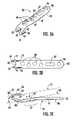
- FIG. 3Ais a top plan view of a 10-hole right offset fracture fixation plate of the present invention, configured for use in the fixation of certain fractures of the ankle;
- FIG. 3Bis a bottom view of the 10-hole right offset fixation plate
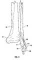
- FIG. 4is a perspective view of the double barreled drill guide of the present invention, shown positioned adjacent the lateral malleolus;
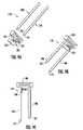
- FIG. 5is an exploded perspective view of the drill guide base assembly and interchangeable drill guide insert
- FIG. 6is an exploded perspective view of the drill guide base assembly
- FIG. 7Ais a perspective view of the body portion of the drill guide base assembly
- FIG. 7Bis a back view of the body portion of the drill guide base assembly
- FIG. 7Cis a sectional view of the body portion of the drill guide base assembly, taken generally along lines 7 C- 7 C of FIG. 7B ;
- FIG. 8Ais an exploded perspective view of the interchangeable guide wire insert
- FIG. 8Bis a side view of the interchangeable guide wire insert
- FIG. 8Cis a bottom plan view of an insert sleeve of the interchangeable guide wire assembly
- FIG. 8Dis a side sectional view of an insert sleeve of the interchangeable guide wire assembly, taken generally along lines 8 D- 8 D of FIG. 8C ;
- FIG. 9Ais an exploded left perspective view of the gauge assembly
- FIG. 9Bis a left perspective view of the gauge assembly
- FIG. 9Cis a top view of the gauge assembly
- FIG. 10is an anterior view, looking posteriorly, of the left tibia and fibula and showing, in particular, a 6-hole fracture fixation plate positioned immediately prior to impacting the hook members and affixation of the plate to the left fibula;
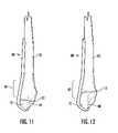
- FIG. 11is an anterior view of the right fibula showing, in particular, the positioning of the 6-hole fracture fixation plate following implantation and reduction of the fracture of the lateral malleolus in which the prong regions cross the fracture site;
- FIG. 12is an anterior view of the right fibula showing, in particular, the positioning of the 6-hole fracture fixation plate following implantation and reduction of the fracture of the lateral malleolus in which the prong regions do not cross the fracture site.
- FIG. 1A simplified anterior view of a portion of the right human ankle is shown in FIG. 1 as comprising fibula 10 , tibia 20 , and talus 30 .
- Right fibula 10is shown having a fracture of the lateral malleolus 11 thereof, creating a small terminal fragment 13 proximate fracture site 12 .
- right tibia 20is shown having a fracture of the medial malleolus 21 thereof, creating a small terminal fragment 23 proximate fracture site 22 .
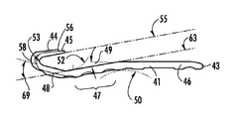
- FIGS. 2A through 2FA six-hole left offset bone plate 40 of the present invention, configured for use in conjunction with fractures of the lateral malleolus, is shown in FIGS. 2A through 2F as comprising an elongated body 41 , having a first end 42 proximate first hook member, or tooth member 44 and second hook member, or tooth member 45 .
- Elongated body 41includes a first region 48 proximate first end 42 , a second region 46 proximate a second end 43 , and an intermediate, angled, or “flared” region 47 disposed between first region 48 and second region 46 .
- Elongated body 41includes a plurality of apertures extending therethrough for use in conjunction with conventional bone screws, including five circular holes 66 , and one slotted hole 67 .
- circular holes 66are in a collectively staggered off-center orientation, relative to a longitudinal axis of elongated body 41 , while slotted hole 67 is centered along this longitudinal axis. Moreover, and as best seen in FIG. 2A , slotted hole 67 and each circular hole 66 includes an associated countersunk, beveled perimeter, relative to the top surface of elongated body 41 , facilitating the frusto-conical heads of conventional bone screws to be fully seated against, and hence in securing engagement with, an associated hole upon implantation.
- angled region 47is generally defined and created by the presence of first radius of curvature 52 relative to the bottom surface of bone plate 40 proximate the juncture of substantially linear first region 48 and substantially linear angled region 47 ; together with the presence of second radius of curvature 50 relative to the top surface of bone plate 40 proximate the juncture of substantially linear second region 46 and angled region 47 .
- the length of the linear angled region 47 and the inclination defined as the angle 49 between a line 63 parallel to linear angled region 47 with the longitudinal axis of the elongated body 41substantially match the length and inclination of the flare of the associated bone requiring fracture fixation.
- substantially linear first region 48may in fact be a curved surface that may be approximated by a best fit inclination angle 49 .
- the bottom surface of elongated body 41 bone plate 40has an overall longitudinal contour which substantially corresponds to the flared profile of the distal end of the human fibula proximate the lateral malleolus.
- angled region 47 , first region 48 , and second region 46may be modified during the manufacturing process to create a hooked bone plate specifically tailored for other sites of application having a bone surface flare superficially proximate the terminal end, such as the medial malleolus, olecranon, proximal ulna, proximal femur, proximal fifth metatarsal, proximal or distal humerus, or other such sites of application.
- the length, contour and relative angling of linear angled region 47 , relative to first region 48 and second region 46is designed and to match the flare of the surface contour of the site of application using an electronically scanned or mathematical three-dimensional model of the site of application, such as the lateral malleolus or olecranon as examples.
- a three-dimensional mathematical model of a particular bone having a flared surface region proximate its terminal endis created, using a three-dimensional scan of either an actual human bone or an artificial model of a human bone, or a three-dimensional model created entirely by computer.
- Computer aided drafting softwareis then used in conjunction with this three-dimensional mathematical model of the bone to create a bone plate of the present invention having a back surface profile of angled region 47 , first region 48 and second region 46 such that, when the prong members are impacted proximate the terminal end of the bone, this back surface profile substantially corresponds to the adjacent flared contour of the bone, such that the bone plate rests substantially adjacent the bone.
- first angle of curvature 52has a radius of approximately 0.380 inches, yielding a first curved bend angle 69 of approximately 25° at the junction of the bottom surface of angled region 47 and the bottom surface of first region 48 of elongated body 41 .
- second angle of curvature 50has a radius of approximately 0.500 inches, yielding a second curved bend angle 49 of approximately 10° at the junction of the bottom surface of angled region 47 and the bottom surface of second region 46 of elongated body 41 .
- these two bend anglesare achieved through curvature of portions elongated body 41 , sharper bends, rather than more gentle curves, may alternatively be used.
- First hook member 44includes curved region 58 , having an apex 54 and curving from first region 48 of elongated body 41 , curving back upon the bottom surface of elongated body 41 , back towards second end 43 and terminating in first pointed prong region 61 .
- second hook member 45includes curved region 53 , having an apex 59 and curving from first region 48 of elongated body 41 , curving back upon the bottom surface of elongated body 41 , back towards second end 43 and terminating in second pointed prong region 56 .
- first prong region 61 and second prong region 56both have a length of approximately 0.390 inches, as measured from apex to tip.
- hook plate 40is not bilaterally symmetrical, relative to the longitudinal axis of elongated body 41 .
- curved region 58 and its apex 54 of first hook member 44is more distally spaced than curved region 53 and its apex 59 , relative to both first end 42 and second end 43 of elongated body 41 .
- apex 54 of first hook member 44extends approximately 2 millimeters farther than apex 59 of second hook member 45 , relative to second end 41 of elongated body 41 .
- This asymmetrical configurationpermits hook members 44 and 45 , hook plate 40 overall, to more closely approximate the often asymmetric contour of the distal surface of the fibula at the lateral malleolus, upon securement of hook plate 40 across the fracture site.
- the surgeonis provided with a selection of plates in which the apex 54 of first hook 44 extends the same distance as the apex of 59 of the second hook member 45 (i.e., a bilaterally symmetrical hook plate); as well as a plate in which the apex 59 of second hook 45 extends 2 mm farther than the apex 54 of first hook 44 (i.e., a right offset plate). It can be seen by those skilled in the art that these variations can be values other than 2 mm and are intended to accommodate variability of the surface anatomy at the site of application.
- hook plate 40has an arcuate cross section and bottom surface, along substantially all of the length of elongated body 41 . This curved bottom surface permits hook plate 40 to more closely approximate the curved longitudinal surface of the fibula, upon securement of hook plate 40 across the fracture site.
- prong region 56 of second hook member 45has a longitudinal axis 55 .
- Angled region 47 of elongated body 41has a longitudinal axis 63 .
- longitudinal axis 55 of second hook member 45is substantially parallel to longitudinal axis 63 of angled region 47 .
- prong region 61 of first prong member 44likewise has a longitudinal axis that is substantially parallel to longitudinal axis 63 of angled region 47 . As explained in detail below, this parallel relationship is critical to allow hook plate 40 to seat congruently against the curved profile of the lateral malleolus as the hook members are impacted into a terminal fragment.
- FIGS. 3A and 3Bshow another, ten-hole embodiment of the present invention, configured for use in conjunction with fractures of the right lateral malleolus.
- bone plate 70is shown as comprising elongated body 71 , having a first end 72 proximate first hook member, or tooth member 74 and second hook member, or tooth member 75 , and a second end 75 .
- Elongated body 71includes a plurality of apertures therethrough for use in conjunction with conventional bone screws, including nine circular holes 78 , and one slotted hole 79 .
- First hook member 74includes a first curved region having an apex 76 .
- Second hook member 75includes a curved region having an apex 77 .
- bone plate 70While bone plate 70 likewise displays bilateral asymmetry relative to its longitudinal axis, it is second hook member 75 having apex 77 , on the right side of the bone plate, that is more distally spaced from first end 72 and second end 73 of elongated body 71 .
- first hook member 44having apex 54 , on the left side of the bone plate, that is more distally spaced from first end 42 and second end 43 of elongated body 41 .
- This “mirror image” general configuration of bone plate 70 , relative to bone plate 40 ,permits bone plate 70 to more closely approximate the curvilinear contoured distal surface of the right fibula at the lateral malleolus, upon securement of hook plate 70 across a fracture site.
- each bone plateincludes one slotted or oval hole for use in cooperation with bone screws, with the remaining holes being circular, other combinations of slotted and round bone screw accepting holes may alternatively be used.
- the hooksmay be of identical length.
- the hook plate of the present inventionis constructed of wrought 18chromium-14nickel-2.5molybdenum stainless steel, having a tensile strength of at least 135 Kips per square inch (KSI), and meeting the chemical and mechanical properties established by the ASTM-F139 standard.
- Other materialssuch as titanium, titanium alloy, or medical grade polymers may alternatively be used.
- the present inventionalso comprises a double barreled drill guide, configured to direct a drill or K-wire in the proper depth and angle, relative to the lateral malleolus, such that, after pilot holes are drilled for the hook members and upon subsequently impacting the hook members of the present hook plate, the bottom surface of the hook plate tracks, and, when fully seated, is substantially adjacent, the surface contour of the lateral malleolus and the adjacent lateral surface of the fibula.
- the double barreled drill guide of the present inventionis shown in FIGS. 4 and 5 as comprising drill guide base assembly 100 . In addition, this guide may also be used with an interchangeable drill guide insert 140 .
- Drill guide base assembly 100is shown in FIGS. 5 through 7C as comprising body portion 111 , two base sleeves 120 , and base positioning member 130 .
- Body portion 111has two apertures 114 extending therethrough, and two arm members 113 , each having an associated aperture 112 extending therethrough.
- apertures 112 and 114are canted slightly towards each other by a predetermined angle 115 , relative to their respective longitudinal axes.
- predetermined angle 115is a slight, acute approximately 3 degrees. This slight angle accounts for a certain amount of relative flex in the components of the drill guide and results in a substantially parallel alignment of the sleeves and the base positioning member upon application of the base positioning member against a superficial surface of the terminal end of the bone.
- no predetermined angle 115is employed, as the sleeves and base positioning member have longitudinal axes that are substantially parallel to each other.
- thisplaces each of base sleeves 120 at predetermined angle 115 , canted towards base positioning member 130 .
- Thislikewise places the sleeves of interchangeable drill guide insert 140 at predetermined angle 115 , canted towards base positioning member 130 , upon insertion of the drill guide insert 140 into base assembly 100 .
- the two pilot holes for the hook members of the present inventionare drilled at predetermined angle 115 , relative to base positioning member 130 .
- Body portion 113is preferably constructed of a surgical stainless steel material, such as type 303 surgical stainless steel.
- Base sleeve 120is shown in FIG. 6 as comprising a generally tubular body having a first end 121 , shoulder 122 , collar region 123 , and second end.
- First end 121has a chamfered and serrated configuration, permitting drill guide base assembly 100 to grip the distal surface of the lateral malleolus when positioned prior to drilling pilot holes for the hook members of the bone plate as shown in FIG. 4 , serving to inhibit unwanted slippage of the overall drill guide.
- An internal channelcommunicates between openings at first end 121 and second end 122 , and is sized to axially receive a drill.
- collar region 123has a length of approximately 0.400 inches
- base sleeve 120has an overall length of approximately 1.025 inches.
- Base sleeve 120is preferably constructed of a surgical stainless steel material, such as type 455 surgical stainless steel, condition H-900.
- base positioning member 130is substantially U-shaped, having two elongated arms 131 and U-shaped end 132 .
- Base positioning member 130is preferably constructed of a stainless steel material, such as type 316LS stainless steel having a minimum ultimate tensile strength of 160 KSI.
- base positioning member 130may be of the form of a plate having a contoured surface approximating the contoured elongated body of the bone plate to be implanted, or one or more pins (not shown).
- Interchangeable drill guide insert 140is shown in FIGS. 8A through 8D as comprising generally T-shaped body 150 and two tubular insert sleeves 160 .
- T-shaped body 150includes two apertures 151 extending therethrough, each accepting an associated insert sleeve 160 , which is assembled by press-fitting each inner sleeve 160 into an associated aperture 151 .
- T-shaped body 150Two inwardly curving recesses extending along T-shaped body 150 have a radius of curvature coinciding with the exterior surface of collar region 123 of base sleeve 120 of drill guide base assembly 100 , serving to further secure interchangeable drill guide insert 140 to drill guide base assembly 100 , as tubular insert sleeves 160 are advanced within associated base sleeves 120 until T-shaped body 150 is fully seated adjacent body portion 111 of drill guide base assembly 100 .
- T-shaped body 150is preferably constructed of a surgical stainless steel material, such as type 303 surgical stainless steel.
- Each insert sleeve 160includes a tapered first end 161 , second end 162 , and an internal channel 163 communicating between openings at first end 161 and second end 162 .
- This internal channelis sized to accommodate a guide wire of a predetermined size, such as a 0.9 millimeter Kirshner wire, or K-wire, to be used in conjunction with a 2.0 mm cannulated drill that is subsequently guided over the wire upon removal of the double barreled drill guide, creating the pilot holes to accept axial impacting of the hook members of the present bone plate.
- insert sleeve 150is approximately 1.150 inches in length.
- Insert sleeve 160is preferably constructed of a surgical stainless steel material, such as type 455 surgical stainless steel, condition H-900.
- T-shaped body 150includes laser-etched indicia 152 , indicating the size of guide wire accommodated by the present interchangeable drill guide insert 140 , in this case a 0.9 millimeter guide wire.
- laser-etched indicia 152is changed as necessary indicate the particular drill or guide wire size for each variation of interchangeable drill guide insert 140 .
- drill guide base assembly 100also releasably accepts a reversible gauge assembly 170 , shown in FIGS. 9A through 9C as comprising T-shaped gauge body 180 , first cylindrical elongated member, or trocar 190 having tapered end 191 , and second cylindrical elongated member, or trocar 200 having tapered end 201 .
- T-shaped body 180includes two apertures 181 extending therethrough, each accepting an associated cylindrical trocar, and is assembled by press-fitting the trocars into associated apertures.
- T-shaped body 180Two inwardly curving recesses extending along T-shaped body 180 have a radius of curvature coinciding with the exterior surface of collar region 123 of base sleeve 120 of drill guide base assembly 100 , serving to further secure gauge assembly 170 to drill guide base member 100 , as cylindrical trocars 190 and 200 are advanced within associated base sleeves 120 until T-shaped body 180 is fully seated adjacent body portion 111 of drill guide base member 100 .
- T-shaped body 180further includes laser etched indicia 183 and 184 , indicating “LEFT” and “RIGHT”, respectively, on opposing sides of the T-shaped body.
- T-shaped body 180is preferably constructed of a surgical stainless steel material, such as type 303 surgical stainless steel.
- first trocar 190 and second 200are of different lengths, with first trocar 190 being longer than trocar 200 .
- first trocar 190is approximately 2 mm longer than second trocar 200 , with first trocar being approximately 1.273 inches in length, and second trocar being approximately 1.150 inches in length.
- This differentialpermits a surgeon, prior to drilling any pilot holes, to use reversible gauge assembly 170 to confirm appropriate use of either a left or right offset hook plate of the present invention to properly accommodate the inclination of the bone curvature at the entry sites for the hooks and permit the hook plate to be properly seated adjacent the fibula upon impacting the hook members.
- gauge assembly 170is inserted into drill guide base assembly 100 .
- the differential in lengths of trocars 190 and 200will approximate the curvature of the lateral malleolus at the distal end of the fibula, and gauge assembly 170 will be substantially fully seated within base assembly 100 .
- gauge assembly 170does not substantially fully seat within base assembly 100 , this is a visual indication that, since the differential in length of the trocars does not follow the contoured distal surface of the lateral malleolus, the indicia facing outwardly or laterally is most likely incorrect. In this case, the gauge assembly 170 can be withdrawn and flipped, and then reinserted to determine if the opposite offset hook plate is required. If the gauge assembly fully seats, it is indicative of the proper offset plate to use. If the gauge assembly does not seat when inserted with either attitude, it is indicative that a zero offset, bilaterally symmetrical plate is required.
- hook members 44 and 45 of hook plate 40are longitudinally advanced into the pilot holes along longitudinal axis 55 of the hook members, using a hammer or other suitable instrument. Since the drill guide references the proper entry site and trajectory of the drill holes, impaction of the plate 40 into bone causes the plate to advance along longitudinal axis 63 . When fully seated, first region 46 , second region 48 , and intermediate angled region 47 come to lie congruently along the curved surface of the bone.
- This anatomic fit of the plate against the boneis the result of designing the longitudinal axis 55 of the hooks to be parallel to the longitudinal axis 63 of the intermediate region 47 , and to the creation of the specific entry site in the bone using the double barreled guide assembly 70 that matches the depth and trajectory of hooks 44 and 45 .
- thiscauses elongated body 41 of hook plate 40 to come to rest substantially adjacent the distal end of the fibula, with longitudinal axis 63 of angled region 47 substantially parallel to and coinciding with the flared end of the fibula at the lateral malleolus, as shown in FIGS. 11 and 12 .
- Bone screwsare then placed through appropriate circular and slotted holes of hook plate 40 and into the fibula, as desired, to secure hook plate 40 in place.
- a drillis used to prepare pilot holes in the lateral malleolus to receive the hook members, for patients with relatively soft bone, a surgeon may potentially opt to forego the preparation of pilot holes, and axially hammer the hook members of the bone plate of the present invention directly into place.
- the embodiment of the present invention discussed aboveis designed for use in conjunction with fractures of the lateral malleolus of the fibula, it may also be used in the configuration discussed above in conjunction with fractures of the medial malleolus of the tibia or other sites as discussed previously.
- the overall lengths of the angled region, first region and second region of the elongated body, as well as the relative angles of the angled region with respect to the adjacent first and second regions of the elongated bodymay be modified to more closely accommodate the terminal ends of other bones, such as the medial malleolus of the tibia, for the treatment of fractures thereof.
- the present inventionalso comprises kits of combinations of the components described above.
- a plurality of hook plates of multiple sizesfrom four-hole to fifteen-hole embodiments in both left and right offset variations, and possibly with zero offset variations, may be provided in kit form so that appropriately sized and configured hook plates of the present invention are readily available at a hospital or trauma center.
- one or more hook platesmay be provided in kit form in combination with the double barreled drill guide of the present invention.
- the double barreled drill guideeither alone or as a part of a kit of one or more hook plates, may itself be provided as a kit or sub-kit including the base assembly, interchangeable drill guides sized to accommodate guide wires and/or non-cannulated drills of varying sizes, and the gauge assembly.
Landscapes
- Health & Medical Sciences (AREA)
- Orthopedic Medicine & Surgery (AREA)
- Surgery (AREA)
- Life Sciences & Earth Sciences (AREA)
- Heart & Thoracic Surgery (AREA)
- Veterinary Medicine (AREA)
- Engineering & Computer Science (AREA)
- Biomedical Technology (AREA)
- Nuclear Medicine, Radiotherapy & Molecular Imaging (AREA)
- Medical Informatics (AREA)
- Molecular Biology (AREA)
- Animal Behavior & Ethology (AREA)
- General Health & Medical Sciences (AREA)
- Public Health (AREA)
- Neurology (AREA)
- Dentistry (AREA)
- Oral & Maxillofacial Surgery (AREA)
- Surgical Instruments (AREA)
Abstract
Description
Claims (8)
Priority Applications (6)
| Application Number | Priority Date | Filing Date | Title |
|---|---|---|---|
| US12/114,916US8177822B2 (en) | 2008-05-05 | 2008-05-05 | Contoured bone plate for fracture fixation having hook members and drill guide for same |
| AU2009200853AAU2009200853B2 (en) | 2008-05-05 | 2009-03-04 | Contoured bone plate for fracture fixation having hook members and drill guide for same |
| US13/103,658US9636157B2 (en) | 2008-05-05 | 2011-05-09 | Contoured bone plate for fracture fixation having hook members |
| US13/598,234US8821508B2 (en) | 2008-05-05 | 2012-08-29 | Holder/impactor for contoured bone plate for fracture fixation |
| US13/598,206US9283010B2 (en) | 2008-05-05 | 2012-08-29 | Contoured bone plate for fracture fixation having hook members and holder/impactor for same |
| US14/333,797US9089376B2 (en) | 2008-05-05 | 2014-07-17 | Combination holder/impactor and bone plate for fracture fixation |
Applications Claiming Priority (1)
| Application Number | Priority Date | Filing Date | Title |
|---|---|---|---|
| US12/114,916US8177822B2 (en) | 2008-05-05 | 2008-05-05 | Contoured bone plate for fracture fixation having hook members and drill guide for same |
Related Child Applications (1)
| Application Number | Title | Priority Date | Filing Date |
|---|---|---|---|
| US13/103,658DivisionUS9636157B2 (en) | 2008-05-05 | 2011-05-09 | Contoured bone plate for fracture fixation having hook members |
Publications (2)
| Publication Number | Publication Date |
|---|---|
| US20090275991A1 US20090275991A1 (en) | 2009-11-05 |
| US8177822B2true US8177822B2 (en) | 2012-05-15 |
Family
ID=41257589
Family Applications (2)
| Application Number | Title | Priority Date | Filing Date |
|---|---|---|---|
| US12/114,916Active2030-12-14US8177822B2 (en) | 2008-05-05 | 2008-05-05 | Contoured bone plate for fracture fixation having hook members and drill guide for same |
| US13/103,658Active2030-12-17US9636157B2 (en) | 2008-05-05 | 2011-05-09 | Contoured bone plate for fracture fixation having hook members |
Family Applications After (1)
| Application Number | Title | Priority Date | Filing Date |
|---|---|---|---|
| US13/103,658Active2030-12-17US9636157B2 (en) | 2008-05-05 | 2011-05-09 | Contoured bone plate for fracture fixation having hook members |
Country Status (2)
| Country | Link |
|---|---|
| US (2) | US8177822B2 (en) |
| AU (1) | AU2009200853B2 (en) |
Cited By (25)
| Publication number | Priority date | Publication date | Assignee | Title |
|---|---|---|---|---|
| US20130046349A1 (en)* | 2008-05-05 | 2013-02-21 | Trimed, Incorporated | Contoured bone plate for fracture fixation having hook members and holder/impactor for same |
| US20140074174A1 (en)* | 2012-09-12 | 2014-03-13 | Timothy G. SCHACHERER | Triceps-Sparing Olecranon Fracture Repair Device and System |
| CN104013458A (en)* | 2014-06-16 | 2014-09-03 | 薛兆龙 | Humerus greater tuberosity locking plate |
| EP2870935A2 (en) | 2013-11-08 | 2015-05-13 | Robert J. Medoff | Drill guides and inserters for bone plates having hook members |
| US9066733B2 (en) | 2010-04-29 | 2015-06-30 | DePuy Synthes Products, Inc. | Orthognathic implant and methods of use |
| US9277948B2 (en) | 2010-04-29 | 2016-03-08 | DePuy Synthes Products, Inc. | Orthognathic implant and methods of use |
| US9317631B2 (en) | 2012-05-03 | 2016-04-19 | DePuy Synthes Products, Inc. | Surgical guide with cut resistant inserts |
| US9375297B2 (en) | 2012-05-17 | 2016-06-28 | DePuy Synthes Products, Inc. | Method of surgical planning |
| US9411939B2 (en) | 2012-09-12 | 2016-08-09 | DePuy Synthes Products, Inc. | Method for producing patient-specific plate |
| US9421103B2 (en) | 2012-04-05 | 2016-08-23 | Orthohelix Surgical Designs, Inc. | Lateral ankle fusion plate system and jig, and method for use therewith |
| US9433452B2 (en) | 2012-08-03 | 2016-09-06 | Nextremity Solutions, Llc | Bone fixation device and method |
| US10192002B2 (en) | 2013-01-04 | 2019-01-29 | DePuy Synthes Products, Inc. | Method for designing and manufacturing a bone implant |
| USD840035S1 (en) | 2015-01-07 | 2019-02-05 | Nextremity Solutions, Inc. | Bone fixation implant |
| US10231762B2 (en) | 2016-03-01 | 2019-03-19 | Advanced Orthopaedic Solutions, Inc. | Bone plate system |
| US10245088B2 (en) | 2015-01-07 | 2019-04-02 | Treace Medical Concepts, Inc. | Bone plating system and method |
| US10245086B2 (en) | 2015-02-18 | 2019-04-02 | Treace Medical Concepts, Inc. | Bone plating kit for foot and ankle applications |
| US10456266B2 (en) | 2017-08-10 | 2019-10-29 | Hayward Surgical, L.L.C. | Apparatuses for distal fibula replacement, and related methods |
| US10792081B2 (en) | 2014-08-28 | 2020-10-06 | Nextremity Solutions, Inc. | Bone fixation devices and methods |
| US11051804B2 (en)* | 2018-07-02 | 2021-07-06 | DePuy Synthes Products, Inc. | Orthopedic fixation system and method of use thereof |
| US11337739B2 (en) | 2017-12-20 | 2022-05-24 | Glabs X, Llc | Multiplanar fixation plate for fracture repair |
| US11376129B2 (en) | 2017-08-10 | 2022-07-05 | Hayward Surgical, L.L.C. | Apparatuses for distal fibula replacement and related methods |
| US11583323B2 (en) | 2018-07-12 | 2023-02-21 | Treace Medical Concepts, Inc. | Multi-diameter bone pin for installing and aligning bone fixation plate while minimizing bone damage |
| US11771481B2 (en) | 2021-03-08 | 2023-10-03 | Zimmer Biomet CMF and Thoracic, LLC | Sternal plates and methods of use |
| US11890039B1 (en) | 2019-09-13 | 2024-02-06 | Treace Medical Concepts, Inc. | Multi-diameter K-wire for orthopedic applications |
| US12440250B2 (en) | 2024-02-05 | 2025-10-14 | Treace Medical Concepts, Inc. | Multi-diameter K-wire for orthopedic applications |
Families Citing this family (69)
| Publication number | Priority date | Publication date | Assignee | Title |
|---|---|---|---|---|
| US20090228010A1 (en) | 2008-03-10 | 2009-09-10 | Eduardo Gonzalez-Hernandez | Bone fixation system |
| AU2008354730A1 (en) | 2008-04-17 | 2009-10-22 | Toby Orthopaedics, Inc. | Soft tissue attachment system and clip |
| CN102740786A (en)* | 2009-12-22 | 2012-10-17 | 托比骨科有限公司 | Bone plate and tool assembly and method for use thereof |
| US8961573B2 (en) | 2010-10-05 | 2015-02-24 | Toby Orthopaedics, Inc. | System and method for facilitating repair and reattachment of comminuted bone portions |
| CN101947127B (en)* | 2010-10-25 | 2012-03-21 | 唐佩福 | Percutaneous ectotrochanter fixer for intertrochanteric fracture |
| WO2012058448A2 (en) | 2010-10-27 | 2012-05-03 | Toby Orthopaedics, Llc | System and method for fracture replacement of comminuted bone fractures or portions thereof adjacent bone joints |
| DE102010061777B4 (en)* | 2010-11-23 | 2019-08-14 | Siemens Healthcare Gmbh | Method for determining a parameter of a fixing element for an implant to be fixed to a bone |
| WO2012119146A2 (en) | 2011-03-03 | 2012-09-07 | Toby Orthopaedics, Llc | Anterior lesser tuberosity fixed angle fixation device and method of use associated therewith |
| US8926661B2 (en) | 2011-06-02 | 2015-01-06 | Smith & Nephew, Inc. | Surgical fastening |
| EP2564797B1 (en)* | 2011-08-31 | 2020-10-14 | Stryker European Holdings I, LLC | Bone place with hook portion |
| WO2013036582A1 (en)* | 2011-09-06 | 2013-03-14 | Skeletal Dynamics, L.L.C. | Fracture fixation plate, system and methods of use |
| US9220549B2 (en)* | 2011-09-27 | 2015-12-29 | Steven Glickel | Distal radius volar locking plate with extension for ulnar volar fragment |
| US9271772B2 (en) | 2011-10-27 | 2016-03-01 | Toby Orthopaedics, Inc. | System and method for fracture replacement of comminuted bone fractures or portions thereof adjacent bone joints |
| US9730797B2 (en) | 2011-10-27 | 2017-08-15 | Toby Orthopaedics, Inc. | Bone joint replacement and repair assembly and method of repairing and replacing a bone joint |
| US11123117B1 (en) | 2011-11-01 | 2021-09-21 | Nuvasive, Inc. | Surgical fixation system and related methods |
| US9402667B2 (en) | 2011-11-09 | 2016-08-02 | Eduardo Gonzalez-Hernandez | Apparatus and method for use of the apparatus for fracture fixation of the distal humerus |
| US10610299B2 (en)* | 2011-12-14 | 2020-04-07 | Stryker European Holdings I, Llc | Technique for generating a bone plate design |
| CA2823403C (en)* | 2012-08-29 | 2018-09-25 | Trimed, Incorporated | Contoured bone plate for fracture fixation having hook members and holder/impactor for same |
| US9949744B2 (en)* | 2012-08-30 | 2018-04-24 | Wright Medical Technology, Inc. | Implant suitable for calcaneal osteotomy |
| US9283008B2 (en) | 2012-12-17 | 2016-03-15 | Toby Orthopaedics, Inc. | Bone plate for plate osteosynthesis and method for use thereof |
| WO2014106778A1 (en)* | 2013-01-03 | 2014-07-10 | Glickel Steven | Distal radius volar locking plate with extension for ulnar volar fragment |
| AU2014228420B2 (en) | 2013-03-15 | 2018-11-08 | Smith & Nephew, Inc. | Surgical fastening |
| US9333014B2 (en) | 2013-03-15 | 2016-05-10 | Eduardo Gonzalez-Hernandez | Bone fixation and reduction apparatus and method for fixation and reduction of a distal bone fracture and malunion |
| US9463053B2 (en)* | 2014-12-08 | 2016-10-11 | Jonathan P. GARINO | Fracture plating |
| TWI544894B (en)* | 2015-01-29 | 2016-08-11 | 愛派司生技股份有限公司 | A securing bone plate |
| CN104825216A (en)* | 2015-05-27 | 2015-08-12 | 熊静 | Metaphysis pressurizing fixator |
| US11197682B2 (en) | 2015-08-27 | 2021-12-14 | Globus Medical, Inc. | Proximal humeral stabilization system |
| US11076898B2 (en) | 2015-08-27 | 2021-08-03 | Globus Medical, Inc. | Proximal humeral stabilization system |
| US10687874B2 (en) | 2015-08-27 | 2020-06-23 | Globus Medical, Inc | Proximal humeral stabilization system |
| US10130402B2 (en) | 2015-09-25 | 2018-11-20 | Globus Medical, Inc. | Bone fixation devices having a locking feature |
| US9974581B2 (en) | 2015-11-20 | 2018-05-22 | Globus Medical, Inc. | Expandable intramedullary systems and methods of using the same |
| US20170164961A1 (en)* | 2015-12-11 | 2017-06-15 | Smith & Nephew, Inc. | Coracoid drill guide and method of use thereof |
| US9795411B2 (en) | 2016-03-02 | 2017-10-24 | Globus Medical, Inc. | Fixators for bone stabilization and associated systems and methods |
| US10531905B2 (en) | 2016-04-19 | 2020-01-14 | Globus Medical, Inc. | Implantable compression screws |
| AU2017274445B2 (en)* | 2016-06-02 | 2022-06-16 | In2Bones Usa, Llc | Plantar bone fusion plate |
| CN109922741B (en)* | 2016-06-02 | 2022-11-08 | 联骨美国有限责任公司 | Foot sole bone fusion plate |
| US11213327B2 (en) | 2016-08-17 | 2022-01-04 | Globus Medical, Inc. | Fracture plates, systems, and methods |
| US11432857B2 (en) | 2016-08-17 | 2022-09-06 | Globus Medical, Inc. | Stabilization systems |
| US10687873B2 (en) | 2016-08-17 | 2020-06-23 | Globus Medical Inc. | Stabilization systems |
| US10383668B2 (en) | 2016-08-17 | 2019-08-20 | Globus Medical, Inc. | Volar distal radius stabilization system |
| US10575884B2 (en) | 2016-08-17 | 2020-03-03 | Globus Medical, Inc. | Fracture plates, systems, and methods |
| US10420596B2 (en) | 2016-08-17 | 2019-09-24 | Globus Medical, Inc. | Volar distal radius stabilization system |
| US11197701B2 (en) | 2016-08-17 | 2021-12-14 | Globus Medical, Inc. | Stabilization systems |
| US11141204B2 (en) | 2016-08-17 | 2021-10-12 | Globus Medical Inc. | Wrist stabilization systems |
| US10751098B2 (en) | 2016-08-17 | 2020-08-25 | Globus Medical Inc. | Stabilization systems |
| US11331128B2 (en) | 2016-08-17 | 2022-05-17 | Globus Medical Inc. | Distal radius stabilization system |
| US10299847B2 (en) | 2016-09-22 | 2019-05-28 | Globus Medical, Inc. | Systems and methods for intramedullary nail implantation |
| US10881438B2 (en) | 2017-03-10 | 2021-01-05 | Globus Medical, Inc. | Clavicle fixation system |
| US10368928B2 (en) | 2017-03-13 | 2019-08-06 | Globus Medical, Inc. | Bone stabilization systems |
| US10905477B2 (en) | 2017-03-13 | 2021-02-02 | Globus Medical, Inc. | Bone stabilization systems |
| US10856920B2 (en) | 2017-09-13 | 2020-12-08 | Globus Medical Inc. | Bone stabilization systems |
| US11096730B2 (en) | 2017-09-13 | 2021-08-24 | Globus Medical Inc. | Bone stabilization systems |
| US12318122B2 (en) | 2017-09-13 | 2025-06-03 | Globus Medical, Inc. | Bone stabilization systems |
| CN109833085A (en)* | 2017-11-28 | 2019-06-04 | 上海市第六人民医院 | A kind of double barb internal malleolus anatomical plates |
| US11071570B2 (en) | 2018-03-02 | 2021-07-27 | Globus Medical, Inc. | Distal tibial plating system |
| US11224468B2 (en) | 2018-03-02 | 2022-01-18 | Globus Medical, Inc. | Distal tibial plating system |
| US11141172B2 (en) | 2018-04-11 | 2021-10-12 | Globus Medical, Inc. | Method and apparatus for locking a drill guide in a polyaxial hole |
| US12295628B2 (en) | 2018-11-01 | 2025-05-13 | Howmedica Osteonics Corp. | Device for fixating orthopedic injury |
| US11202663B2 (en) | 2019-02-13 | 2021-12-21 | Globus Medical, Inc. | Proximal humeral stabilization systems and methods thereof |
| WO2021026354A1 (en)* | 2019-08-06 | 2021-02-11 | Exactech, Inc. | Acromion fracture repair system |
| US12185995B2 (en) | 2019-10-09 | 2025-01-07 | Globus Medical, Inc. | Bone stabilization systems |
| US11129627B2 (en) | 2019-10-30 | 2021-09-28 | Globus Medical, Inc. | Method and apparatus for inserting a bone plate |
| US11723647B2 (en) | 2019-12-17 | 2023-08-15 | Globus Medical, Inc. | Syndesmosis fixation assembly |
| US12343050B2 (en)* | 2021-08-17 | 2025-07-01 | Ps Ortho Llc | Bone fixation devices, systems, and methods |
| US12133667B2 (en) | 2021-10-22 | 2024-11-05 | Orthopedic Designs North America, Inc. | Self-contouring plate system for bone fractures |
| US12433650B2 (en) | 2021-10-22 | 2025-10-07 | Orthopedic Designs North America, Inc. | Self-contouring plate system for bone fractures with anti-rotation stop |
| US12064150B2 (en) | 2022-01-19 | 2024-08-20 | Globus Medical Inc. | System and method for treating bone fractures |
| US12262900B2 (en)* | 2022-07-06 | 2025-04-01 | Vilex Llc | Bone hook plate apparatus, system, and method |
| US20250000526A1 (en)* | 2023-06-29 | 2025-01-02 | Trimed Inc. | Method of and apparatus for fixing an implant with respect to first and second bone parts |
Citations (2)
| Publication number | Priority date | Publication date | Assignee | Title |
|---|---|---|---|---|
| US20040092947A1 (en)* | 2002-09-30 | 2004-05-13 | Foley Kevin T. | Devices and methods for securing a bone plate to a bony segment |
| US7037308B2 (en) | 2001-02-12 | 2006-05-02 | Medoff Robert J | Implant device for applying compression across a fracture site |
Family Cites Families (5)
| Publication number | Priority date | Publication date | Assignee | Title |
|---|---|---|---|---|
| US3554193A (en)* | 1968-07-05 | 1971-01-12 | Ilias Konstantinou | Femur-setting surgical device |
| US3824995A (en)* | 1972-07-24 | 1974-07-23 | Villiers E | Trochanteric plate |
| US5674222A (en)* | 1994-06-01 | 1997-10-07 | Synthes (U.S.A.) | Forked plate |
| US5871496A (en)* | 1996-03-20 | 1999-02-16 | Cardiothoracic Systems, Inc. | Surgical instrument for facilitating the detachment of an artery and the like |
| US6641582B1 (en)* | 2000-07-06 | 2003-11-04 | Sulzer Spine-Tech Inc. | Bone preparation instruments and methods |
- 2008
- 2008-05-05USUS12/114,916patent/US8177822B2/enactiveActive
- 2009
- 2009-03-04AUAU2009200853Apatent/AU2009200853B2/enactiveActive
- 2011
- 2011-05-09USUS13/103,658patent/US9636157B2/enactiveActive
Patent Citations (2)
| Publication number | Priority date | Publication date | Assignee | Title |
|---|---|---|---|---|
| US7037308B2 (en) | 2001-02-12 | 2006-05-02 | Medoff Robert J | Implant device for applying compression across a fracture site |
| US20040092947A1 (en)* | 2002-09-30 | 2004-05-13 | Foley Kevin T. | Devices and methods for securing a bone plate to a bony segment |
Non-Patent Citations (2)
| Title |
|---|
| Weseley, M.S., et al., The Use of the Zuelzer Hook Plate in Fixation of Olecranon Fractures, The Journal of Bone & Joint Surgery, 1976; 58:859-863. |
| Zuelzer, Wilhelm A., Fixation of Small But Important Bone Fragments With a Hook Plate, The Journal of Bone & Joint Surgery, 1951; 33:430-436. |
Cited By (46)
| Publication number | Priority date | Publication date | Assignee | Title |
|---|---|---|---|---|
| US9283010B2 (en)* | 2008-05-05 | 2016-03-15 | Trimed, Incorporated | Contoured bone plate for fracture fixation having hook members and holder/impactor for same |
| US20130046349A1 (en)* | 2008-05-05 | 2013-02-21 | Trimed, Incorporated | Contoured bone plate for fracture fixation having hook members and holder/impactor for same |
| US8821508B2 (en) | 2008-05-05 | 2014-09-02 | Trimed, Incorporated | Holder/impactor for contoured bone plate for fracture fixation |
| US9381072B2 (en)* | 2010-04-29 | 2016-07-05 | DePuy Synthes Products, Inc. | Orthognathic implant and methods of use |
| US9066733B2 (en) | 2010-04-29 | 2015-06-30 | DePuy Synthes Products, Inc. | Orthognathic implant and methods of use |
| US20150265378A1 (en)* | 2010-04-29 | 2015-09-24 | DePuy Synthes Products, Inc. | Orthognathic implant and methods of use |
| US9277948B2 (en) | 2010-04-29 | 2016-03-08 | DePuy Synthes Products, Inc. | Orthognathic implant and methods of use |
| US11357514B2 (en) | 2010-04-29 | 2022-06-14 | DePuy Synthes Products, Inc. | Orthognathic implant and methods of use |
| US12433605B2 (en) | 2010-04-29 | 2025-10-07 | DePuy Synthes Products, Inc. | Orthognathic implant and methods of use |
| US10080567B2 (en) | 2010-04-29 | 2018-09-25 | DePuy Synthes Products, Inc. | Orthognathic implant and method of use |
| US9855056B2 (en) | 2010-04-29 | 2018-01-02 | DePuy Synthes Products, Inc. | Orthognathic implant and methods of use |
| US9421103B2 (en) | 2012-04-05 | 2016-08-23 | Orthohelix Surgical Designs, Inc. | Lateral ankle fusion plate system and jig, and method for use therewith |
| US9317634B2 (en) | 2012-05-03 | 2016-04-19 | DePuy Synthes Products, Inc. | Surgical guide with cut resistant inserts |
| US9361410B2 (en) | 2012-05-03 | 2016-06-07 | DePuy Synthes Products, Inc. | Surgical guides from scanned implant data |
| US9707044B2 (en) | 2012-05-03 | 2017-07-18 | DePuy Synthes Products, Inc. | Surgical guides from scanned implant data |
| US10467356B2 (en) | 2012-05-03 | 2019-11-05 | DePuy Synthes Products, Inc. | Surgical guide with cut resistant insert |
| US9317631B2 (en) | 2012-05-03 | 2016-04-19 | DePuy Synthes Products, Inc. | Surgical guide with cut resistant inserts |
| US10321959B2 (en) | 2012-05-17 | 2019-06-18 | DePuy Synthes Products, Inc. | Method of surgical planning |
| US9375297B2 (en) | 2012-05-17 | 2016-06-28 | DePuy Synthes Products, Inc. | Method of surgical planning |
| US9433452B2 (en) | 2012-08-03 | 2016-09-06 | Nextremity Solutions, Llc | Bone fixation device and method |
| US10548668B2 (en) | 2012-09-12 | 2020-02-04 | DePuy Synthes Products, Inc. | Method for producing patient-specific plate |
| US9411939B2 (en) | 2012-09-12 | 2016-08-09 | DePuy Synthes Products, Inc. | Method for producing patient-specific plate |
| US9345496B2 (en)* | 2012-09-12 | 2016-05-24 | Timothy G. SCHACHERER | Triceps-sparing olecranon fracture repair device and system |
| US20140074174A1 (en)* | 2012-09-12 | 2014-03-13 | Timothy G. SCHACHERER | Triceps-Sparing Olecranon Fracture Repair Device and System |
| US10192002B2 (en) | 2013-01-04 | 2019-01-29 | DePuy Synthes Products, Inc. | Method for designing and manufacturing a bone implant |
| US10534869B2 (en) | 2013-01-04 | 2020-01-14 | DePuy Synthes Products, Inc. | Method for designing and manufacturing a bone implant |
| US11490906B2 (en) | 2013-11-08 | 2022-11-08 | Trimed Incorporated | Drill guides and inserters for bone plates having hook members |
| EP2870935A2 (en) | 2013-11-08 | 2015-05-13 | Robert J. Medoff | Drill guides and inserters for bone plates having hook members |
| CN104013458A (en)* | 2014-06-16 | 2014-09-03 | 薛兆龙 | Humerus greater tuberosity locking plate |
| US11234743B2 (en) | 2014-08-28 | 2022-02-01 | Nextremity Solutions, Inc. | Bone fixation devices and methods |
| US10792081B2 (en) | 2014-08-28 | 2020-10-06 | Nextremity Solutions, Inc. | Bone fixation devices and methods |
| USD840035S1 (en) | 2015-01-07 | 2019-02-05 | Nextremity Solutions, Inc. | Bone fixation implant |
| US12059185B2 (en) | 2015-01-07 | 2024-08-13 | Treace Medical Concepts, Inc. | Bone plating system and method |
| US11154340B2 (en) | 2015-01-07 | 2021-10-26 | Treace Medical Concepts, Inc. | Bone plating system and method |
| US10245088B2 (en) | 2015-01-07 | 2019-04-02 | Treace Medical Concepts, Inc. | Bone plating system and method |
| US11344347B2 (en) | 2015-02-18 | 2022-05-31 | Treace Medical Concepts, Inc. | Bone plating kit for foot and ankle applications |
| US10245086B2 (en) | 2015-02-18 | 2019-04-02 | Treace Medical Concepts, Inc. | Bone plating kit for foot and ankle applications |
| US10231762B2 (en) | 2016-03-01 | 2019-03-19 | Advanced Orthopaedic Solutions, Inc. | Bone plate system |
| US10456266B2 (en) | 2017-08-10 | 2019-10-29 | Hayward Surgical, L.L.C. | Apparatuses for distal fibula replacement, and related methods |
| US11376129B2 (en) | 2017-08-10 | 2022-07-05 | Hayward Surgical, L.L.C. | Apparatuses for distal fibula replacement and related methods |
| US11337739B2 (en) | 2017-12-20 | 2022-05-24 | Glabs X, Llc | Multiplanar fixation plate for fracture repair |
| US11051804B2 (en)* | 2018-07-02 | 2021-07-06 | DePuy Synthes Products, Inc. | Orthopedic fixation system and method of use thereof |
| US11583323B2 (en) | 2018-07-12 | 2023-02-21 | Treace Medical Concepts, Inc. | Multi-diameter bone pin for installing and aligning bone fixation plate while minimizing bone damage |
| US11890039B1 (en) | 2019-09-13 | 2024-02-06 | Treace Medical Concepts, Inc. | Multi-diameter K-wire for orthopedic applications |
| US11771481B2 (en) | 2021-03-08 | 2023-10-03 | Zimmer Biomet CMF and Thoracic, LLC | Sternal plates and methods of use |
| US12440250B2 (en) | 2024-02-05 | 2025-10-14 | Treace Medical Concepts, Inc. | Multi-diameter K-wire for orthopedic applications |
Also Published As
| Publication number | Publication date |
|---|---|
| AU2009200853B2 (en) | 2014-08-21 |
| US20090275991A1 (en) | 2009-11-05 |
| US20110213420A1 (en) | 2011-09-01 |
| US9636157B2 (en) | 2017-05-02 |
| AU2009200853A1 (en) | 2009-11-19 |
Similar Documents
| Publication | Publication Date | Title |
|---|---|---|
| US8177822B2 (en) | Contoured bone plate for fracture fixation having hook members and drill guide for same | |
| US9283010B2 (en) | Contoured bone plate for fracture fixation having hook members and holder/impactor for same | |
| US11490906B2 (en) | Drill guides and inserters for bone plates having hook members | |
| CA2823403C (en) | Contoured bone plate for fracture fixation having hook members and holder/impactor for same | |
| AU2005275017B2 (en) | Intramedullary fixation assembly and devices | |
| US8685024B2 (en) | Intramedullary fixation device and methods for bone fixation and stabilization | |
| US20080091203A1 (en) | Intramedullary fixation assembly and devices and methods for installing the same | |
| EP3191001B1 (en) | Modular proximal femoral osteotomy blade-plate assembly |
Legal Events
| Date | Code | Title | Description |
|---|---|---|---|
| AS | Assignment | Owner name:MEDOFF, DAVID, CALIFORNIA Free format text:ASSIGNMENT OF ASSIGNORS INTEREST;ASSIGNOR:MEDOFF, ROBERT J.;REEL/FRAME:020932/0819 Effective date:20080508 Owner name:TELLMAN, LARS G., SWEDEN Free format text:ASSIGNMENT OF ASSIGNORS INTEREST;ASSIGNOR:MEDOFF, ROBERT J.;REEL/FRAME:020932/0819 Effective date:20080508 | |
| STCF | Information on status: patent grant | Free format text:PATENTED CASE | |
| FPAY | Fee payment | Year of fee payment:4 | |
| AS | Assignment | Owner name:TRIMED, INCORPORATED, CALIFORNIA Free format text:ASSIGNMENT OF ASSIGNORS INTEREST;ASSIGNORS:MEDOFF, ROBERT J.;TELLMAN, LARS G.;MEDOFF, DAVID;SIGNING DATES FROM 20180419 TO 20180420;REEL/FRAME:045749/0169 | |
| MAFP | Maintenance fee payment | Free format text:PAYMENT OF MAINTENANCE FEE, 8TH YR, SMALL ENTITY (ORIGINAL EVENT CODE: M2552); ENTITY STATUS OF PATENT OWNER: SMALL ENTITY Year of fee payment:8 | |
| MAFP | Maintenance fee payment | Free format text:PAYMENT OF MAINTENANCE FEE, 12TH YR, SMALL ENTITY (ORIGINAL EVENT CODE: M2553); ENTITY STATUS OF PATENT OWNER: SMALL ENTITY Year of fee payment:12 | |
| AS | Assignment | Owner name:TRIMED INC., CALIFORNIA Free format text:CORRECTIVE ASSIGNMENT TO CORRECT THE ASSIGNEE' NAME PREVIOUSLY RECORDED AT REEL: 045749 FRAME: 0169. ASSIGNOR(S) HEREBY CONFIRMS THE ASSIGNMENT;ASSIGNORS:MEDOFF, ROBERT J.;TELLMAN, LARS G.;MEDOFF, DAVID;SIGNING DATES FROM 20180419 TO 20180420;REEL/FRAME:066130/0787 | |
| AS | Assignment | Owner name:TRIMED, INC., CALIFORNIA Free format text:CHANGE OF NAME;ASSIGNOR:TRIMED INC.;REEL/FRAME:068916/0799 Effective date:20240816 |