US8177753B2 - Catheter insertion assembly - Google Patents
Catheter insertion assemblyDownload PDFInfo
- Publication number
- US8177753B2 US8177753B2US11/756,748US75674807AUS8177753B2US 8177753 B2US8177753 B2US 8177753B2US 75674807 AUS75674807 AUS 75674807AUS 8177753 B2US8177753 B2US 8177753B2
- Authority
- US
- United States
- Prior art keywords
- stiffener
- hub
- lumen
- catheter
- valve
- Prior art date
- Legal status (The legal status is an assumption and is not a legal conclusion. Google has not performed a legal analysis and makes no representation as to the accuracy of the status listed.)
- Expired - Fee Related, expires
Links
Images


Classifications
- A—HUMAN NECESSITIES
- A61—MEDICAL OR VETERINARY SCIENCE; HYGIENE
- A61M—DEVICES FOR INTRODUCING MEDIA INTO, OR ONTO, THE BODY; DEVICES FOR TRANSDUCING BODY MEDIA OR FOR TAKING MEDIA FROM THE BODY; DEVICES FOR PRODUCING OR ENDING SLEEP OR STUPOR
- A61M25/00—Catheters; Hollow probes
- A61M25/0097—Catheters; Hollow probes characterised by the hub
- A—HUMAN NECESSITIES
- A61—MEDICAL OR VETERINARY SCIENCE; HYGIENE
- A61M—DEVICES FOR INTRODUCING MEDIA INTO, OR ONTO, THE BODY; DEVICES FOR TRANSDUCING BODY MEDIA OR FOR TAKING MEDIA FROM THE BODY; DEVICES FOR PRODUCING OR ENDING SLEEP OR STUPOR
- A61M25/00—Catheters; Hollow probes
- A61M25/01—Introducing, guiding, advancing, emplacing or holding catheters
- A61M25/0105—Steering means as part of the catheter or advancing means; Markers for positioning
- A61M25/0113—Mechanical advancing means, e.g. catheter dispensers
- A—HUMAN NECESSITIES
- A61—MEDICAL OR VETERINARY SCIENCE; HYGIENE
- A61M—DEVICES FOR INTRODUCING MEDIA INTO, OR ONTO, THE BODY; DEVICES FOR TRANSDUCING BODY MEDIA OR FOR TAKING MEDIA FROM THE BODY; DEVICES FOR PRODUCING OR ENDING SLEEP OR STUPOR
- A61M25/00—Catheters; Hollow probes
- A61M25/0067—Catheters; Hollow probes characterised by the distal end, e.g. tips
- A61M25/0074—Dynamic characteristics of the catheter tip, e.g. openable, closable, expandable or deformable
- A61M25/0075—Valve means
- A61M2025/0076—Unidirectional valves
- A—HUMAN NECESSITIES
- A61—MEDICAL OR VETERINARY SCIENCE; HYGIENE
- A61M—DEVICES FOR INTRODUCING MEDIA INTO, OR ONTO, THE BODY; DEVICES FOR TRANSDUCING BODY MEDIA OR FOR TAKING MEDIA FROM THE BODY; DEVICES FOR PRODUCING OR ENDING SLEEP OR STUPOR
- A61M25/00—Catheters; Hollow probes
- A61M25/01—Introducing, guiding, advancing, emplacing or holding catheters
- A61M25/06—Body-piercing guide needles or the like
- A61M25/0662—Guide tubes
- A61M2025/0681—Systems with catheter and outer tubing, e.g. sheath, sleeve or guide tube
- A—HUMAN NECESSITIES
- A61—MEDICAL OR VETERINARY SCIENCE; HYGIENE
- A61M—DEVICES FOR INTRODUCING MEDIA INTO, OR ONTO, THE BODY; DEVICES FOR TRANSDUCING BODY MEDIA OR FOR TAKING MEDIA FROM THE BODY; DEVICES FOR PRODUCING OR ENDING SLEEP OR STUPOR
- A61M25/00—Catheters; Hollow probes
- A61M25/01—Introducing, guiding, advancing, emplacing or holding catheters
- A61M25/0194—Tunnelling catheters
Definitions
- the present inventionrelates to a catheter insertion assembly for use in placing a catheter into a patient with minimal trauma to the tissues of the patient, particularly at the insertion site, and with a reduced likelihood of air embolism.
- CVCscentral venous catheters
- the Seldinger techniquebegins with obtaining access to a blood vessel with a needle.
- the needleis hollow and, after it is determined that the needle has been inserted into the appropriate blood vessel, a wire is passed through the needle bore into the blood vessel.
- the wireis often referred to as a “guidewire” since its ultimate purpose is to guide a catheter into place.
- the needleis removed by backing the needle over the guidewire while leaving the guidewire in place. Proper placement of the guidewire may be verified by fluoroscopy or other imaging method.
- the guidewireis then used to guide a dilator, if needed, into the blood vessel to widen the opening through the skin and subcutaneous tissue.
- the dilatoris removed while the guidewire is still held in place.
- Multiple dilatorsmay be used, one after the other, until the opening is large enough to receive a catheter introducer.
- the catheter introduceris a short hollow tube which is placed in the opening.
- the introduceris sometimes disposed about the largest dilator and inserted along with the dilator.
- the catheter introduceris inserted subsequent to the removal of the final dilator.
- the catheterWith the introducer in place, the catheter is advanced over the guidewire and through the introducer.
- catheter insertionis accomplished, the introducer is pulled out of the incision and split according to the manufacturer's usage directions so that it can be removed from around the catheter.
- the guidewireis removed either prior to or after the removal of the introducer.
- a catheter introduceris necessary is that most catheters are soft and subject to bending and kinking. Inserting a soft and pliable catheter through the tissue of an insertion site and into the vasculature of a patient, even over a guidewire and after the use of one or more dilators, is difficult. Such an insertion can result in damage to the catheter, to the patient or both.
- Air embolismis the obstruction of a blood vessel by an air bubble.
- a path from the atmosphere to the vasculatureis created. While it is usually possible to keep the path sufficiently obstructed, this is not always the case. Whether through necessity or accident, this path is sometimes opened. If, while this path is opened, the patient takes a deep breath, air will be sucked into the central vessels through the open path. This results in an air embolism. Air embolism is potentially a very serious complication and may be fatal.
- a catheter introducerThe likelihood of an air embolism is greatest when a catheter introducer is used.
- the diameter of a catheter introduceris usually relatively large, i.e. 12 french or more, in order to fulfill its function of allowing insertion of the catheter. It would defeat the purpose of the catheter introducer to include an obstruction therein; as a clear path from outside of the patient's body to the patient's vasculature needs to be available for the catheter to be inserted.
- a needexists for a catheter insertion assembly that reduces insertion trauma and the likelihood or severity of air embolism during catheter insertion into a patient.
- a needalso exists for a catheter insertion assembly that obviates the need for a catheter introducer.
- a catheter insertion assemblycomprises a hub having a proximal end, a distal end and a lumen extending through the hub between the proximal and distal ends.
- a valveis disposed in the lumen of the hub and, up to a first pressure threshold, the valve prevents substantially all fluid flow through the hub lumen in at least one direction.
- the hubalso includes a hollow stiffener having a proximal end and a distal end. The stiffener extends distally of the distal end of the hub and is adapted to be placed within a catheter to be inserted into a patient.
- the stiffenerfurther includes a lumen extending from the proximal to the distal end of the stiffener, which stiffener lumen is in fluid communication with a distal portion of the hub lumen.
- the hub lumenis divided into a hub lumen distal portion and a hub lumen proximal portion.
- One or more irrigation tunnelsmay be provided for liquid exchange between the distal and proximal lumen portions.
- the irrigation tunnelsmay supplement the fluid communication between the stiffener lumen and the distal portion of the hub lumen or may be an alternative thereto.
- a catheteris disposed over the stiffener and is connected to the hub of the insertion assembly.
- the cathetermay be a single lumen or a multi-lumen catheter.
- the catheter, disposed over the stiffener of the insertion assembly,is then inserted over a guidewire and into a patient.
- the guidewireis received in the lumen of the stiffener.
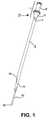
- FIG. 1is a perspective view of the insertion assembly together with a catheter that is to be inserted into a patient;
- FIG. 2is a side view of the insertion assembly showing some hidden line detail with the catheter shown in cross-section to better show the stiffener;
- FIG. 2Ais a cross-sectional detail view of a portion of FIG. 2 taken along cross-sectional line 2 A- 2 A;
- FIG. 3is a side view of a portion of the insertion assembly hub showing some hidden line detail
- FIG. 3Ais a cross-sectional detail view of FIG. 3 taken along cross-sectional line 3 A- 3 A;
- FIG. 4is a side view of a portion of the insertion assembly hub showing some hidden line detail
- FIG. 4Ais a cross-sectional detail view of FIG. 4 taken along cross-sectional line 4 A- 4 A;
- FIG. 5is a perspective view of one embodiment of the valve of the insertion assembly
- FIG. 6is a perspective view of the insertion assembly in use
- FIG. 7is a front view of an embodiment of the valve of the insertion assembly
- FIG. 7Ais a cross-sectional view of the valve of FIG. 7 , taken along cross-sectional line 7 A- 7 A;
- FIG. 8is a cross-sectional detail view of an alternative embodiment of the insertion assembly utilizing the valve of FIG. 7 ;
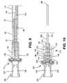
- FIG. 9is a cross-sectional detail view of an alternative embodiment of the insertion assembly showing some hidden-line detail
- FIG. 10is a cross-sectional view of an alternative embodiment of the insertion assembly hub and stiffener showing some hidden-line detail
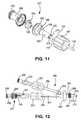
- FIG. 11is an exploded perspective view of the insertion hub shown in FIG. 10 ;
- FIG. 12is a side detail view of the insertion assembly hub shown in FIGS. 10 and 11 in use with a selectively attachable catheter hub and catheter.
- Structures and methods for using an insertion assembly to insert a catheterare shown.
- a broad range of catheter typescan be utilized in combination with the structures herein described, such as chronic hemodialysis catheters, central ports, tunneled central catheters, or other catheters normally requiring a catheter introducer.
- the insertion assembly 10is shown together with a catheter 12 which is to be inserted into the patient.
- the insertion assembly 10is made up of a hub 7 which includes stiffener hub portion 6 , valve hub portion 8 and valve 26 .
- a hub 7which includes stiffener hub portion 6 , valve hub portion 8 and valve 26 .
- Any polymer or material with sufficient formability and strengthmay be used for hub 7 , e.g., polycarbonate.
- Stiffener 40extends distally from hub 7 , is inserted into catheter 12 and is of such a length as to extend at least the entire length of the catheter 12 , and preferably a small distance beyond the distal tip of catheter 12 .
- Stiffener 40has a stiffness greater than the stiffness of the catheter and therefore stiffens the catheter such that the catheter may be inserted into a patient without buckling, even without using a catheter introducer. This minimizes insertion trauma.
- a thermoplastic polyurethane resine.g. ISOPLAST manufactured by Dow Chemical Company of Midland Mich., is an example of a material of appropriate characteristics to impart the proper stiffness to stiffener 40 .
- a stiffener made out of thermoplastic polyurethane resinincluding a central lumen, and having a diameter of approximately 0.056′′, a wall thickness of approximately 0.0085′′ provides satisfactory strength and stiffness characteristics.
- Valve 26is housed within the hub lumen 22 , 24 .
- the valve 26prevents substantially all fluid flow through the hub 7 in at least one direction, e.g. from the atmosphere to inside of the patient, below a first pressure threshold.
- the catheter 12is attached to hub 7 such that fluid flow through the lumens of the catheter 12 is controlled by valve 26 .
- valve 26prevents substantially all air from entering catheter 12 , but can permit fluid flow into the catheter.
- the hub 7 , stiffener 40 and valve 26 of the insertion assembly 10cooperate to both minimize insertion trauma and reduce the likelihood of air embolism.
- FIGS. 3 and 3Ashow the structure of the valve hub portion 8 of hub 7 .
- Valve hub portion 8has a valve hub lumen 22 extending from proximal threaded end 20 to distal connection shoulder 21 near the distal end of the valve hub portion 8 .
- a valve retention collar 34is located within the connection shoulder 21 .
- FIGS. 4 and 4Ashow the structure of the stiffener hub portion 6 of hub 7 .
- Stiffener hub portion 6has a stiffener hub lumen 24 extending from its proximal end 36 to its distal end 33 .
- the diameter of the inside surface of stiffener hub lumen 24varies; such that at one point the inside diameter of stiffener hub lumen 24 is of approximately the same diameter as the outside diameter of stiffener 40 .
- stiffener 40is connected to hub 7 where the inside diameter of stiffener hub lumen 24 is approximately the same as the outside diameter of stiffener 40 .
- This portion of stiffener hub lumen 24is called the stiffener connection portion 25 . Wherever connection between hub 7 and stiffener 40 is made the connection may be, for example, by adhesive, welding, interference fit or press fit.
- Stiffener hub portion 6also has a proximal connection ring 32 adjacent the proximal end 36 . If the stiffener hub portion 6 and the valve hub portion 8 are formed separately, then the connection shoulder 21 of valve hub portion 8 engages the connection ring 32 of the stiffener hub portion 6 . When this occurs, valve hub portion 8 and stiffener hub portion 6 are connected as a single hub 7 and valve hub lumen 22 is in fluid communication with stiffener hub lumen 24 .
- FIG. 5shows valve 26 including an annular shoulder 27 and a valve slit 28 for allowing fluid passage under certain conditions.
- annular shoulder 27abuts valve retention collar 34 of valve hub portion 8 and the side of annular shoulder 27 not abutting valve retention collar 34 is abutted by the proximal end 36 of stiffener hub portion 6 .
- valve 26is inserted into valve hub portion 8 prior to attachment of stiffener hub portion 6 to valve hub portion 8 .
- Valve retention collar 34abuts annular shoulder 27 of valve 26 , seating valve 26 in valve hub portion 8 and, when stiffener hub portion 6 is attached to valve hub portion 8 , valve 26 is trapped in place between valve retention collar 34 and the proximal end 36 of stiffener hub portion 6 .
- Valve 26can be made of any pliable material; in a preferred embodiment the valve material is silicone rubber.
- the function of valve 26is to prevent unwanted fluid flow through catheter 12 but to allow desirable fluid flow.
- the term fluidmeans both liquid and gas.
- One example of unwanted fluid flowis blood from the patient.
- the primary function of valve 26is to prevent air from entering the vasculature of the patient from the atmosphere. By preventing substantially all air from flowing from the proximal end of hub 7 , which is exposed to the atmosphere during portions of the insertion procedure, to catheter 12 , valve 26 prevents air embolism.
- valve 26While preventing unwanted fluid flow, valve 26 does allow fluid flow under specific, controllable conditions.
- slit 28is formed adjacent the center of valve 26 .
- Valve 26being of a pliable material, e.g. silicone rubber, slit 28 will flex open if a large enough pressure, i.e. a “threshold pressure”, is exerted on the slit.
- the term “cracking pressure”is sometimes used in this context and is synonymous with “threshold pressure” as used herein.
- Fluid on one side of valve 26has a first pressure P 1 , as illustrated in FIG. 2A , and fluid on the other side of valve 26 has a second pressure P 2 .
- slit 28flexes open and allows fluid flow from the higher pressure side of the valve to the lesser value pressure side.
- the specific value of the difference between P 1 and P 2is the threshold pressure. Because of the geometry and material characteristics of the valve, there is at least one threshold pressure in each direction and these pressures differ from each other.
- One purpose of the valve 26 allowing fluid flowis so that all air in the catheter 12 may be displaced prior to insertion. As discussed further below, saline is injected through hub 7 prior to the insertion procedure to remove all air from the assembly 10 and catheter 12 .
- the valve 26specifically the ability to overcome the seal created by the valve 26 , allows this to be accomplished.
- Slit 28 in valve 26also allows passage of a guidewire 60 so that the catheter 12 and stiffener 40 may be moved along the guidewire 60 , as will be described below. Threshold pressure will be affected by the presence of guidewire 60 , but much of the valve's effectiveness in preventing fluid flow, e.g. air flow into the patient or blood from the patient, should remain in spite of the presence of guidewire 60 extending through slit 28 .
- FIGS. 7 and 7Adiscloses an alternative embodiment of a valve for use in the present invention.
- Valve 80shares many of the characteristics of valve 26 including function, material, general placement and interaction with the other structural elements of the present catheter insertion assembly.
- Valve 80has a slit 28 in dome portion 84 that has threshold pressures determined by the geometry and material chosen for valve 80 and slit 28 .
- Annular shoulder 27 of valve 80is provided to interact with portions of hub 7 and be retained in place thereby.
- Annular ring 82adds to this retention strength.
- FIG. 8shows valve 80 installed in hub 7 .
- stiffener 40is attached to hub 7 at stiffener connection portion 25 and extends beyond the distal end 33 of hub 7 .
- Stiffener 40terminates at tip 50 and includes stiffener lumen 42 extending the length of the stiffener 40 from the stiffener proximal end to the tip 50 .
- Stiffener lumen 42may be used to accommodate a guidewire 60 (such as those used in the Seldinger technique), which guidewire 60 may extend through the entire apparatus shown in FIG. 2 , from tip 50 through stiffener lumen 42 , valve 26 and hub 7 .
- connection threads 20fluid from a fluid supply source (not shown) attached to connection threads 20 passes through valve hub lumen 22 and through valve 26 if valve 26 is opened by a sufficient pressure threshold being overcome. Fluid passing through valve 26 in a distal direction enters stiffener lumen 42 .
- Stiffener 40may be provided with an irrigation vent 48 adjacent the portion of stiffener 40 attached to stiffener connection portion 25 . Irrigation vent 48 allows liquid introduced to the stiffener lumen 42 to exit the stiffener 40 radially very near the connection portion 25 .
- the stiffener hub portion 6may be provided with one or more irrigation tunnels 70 .
- the irrigation tunnels 70connect lumen 22 of valve hub portion 8 to lumen 24 of stiffener hub portion 6 (assuming the threshold pressure of valve 26 is overcome) such that fluid may pass from valve hub lumen 22 to stiffener hub lumen 24 without having to pass through stiffener lumen 42 and stiffener irrigation vent 48 .
- Irrigation tunnels 70are shown in FIGS. 2 , 2 A, 4 , 4 A and 6 .
- the irrigation tunnels 70have an axis extending parallel to, though radially offset from, the axis of the stiffener hub lumen 24 .
- Each irrigation tunnel 70extends from an irrigation tunnel distal hole 72 terminating at stiffener hub lumen 42 to an irrigation tunnel proximal hole 74 terminating at the proximal end 36 of stiffener hub portion 6 .
- the placement of irrigation tunnel proximal holes 74is such that valve 26 remains effective preventing flow distal of valve slit 28 in appropriate circumstances.
- irrigation tunnel 70provides fluid connection from valve hub lumen 22 to the portion of stiffener hub lumen 24 external to the stiffener 40 that is either alternative or complementary to the fluid connection via stiffener lumen 42 and irrigation vent 48 .
- These fluid connections 48 , 70are used, for example, to displace all air from the insertion assembly 10 and catheter 12 by injecting saline into hub 7 from source connected to connection threads 20 .
- the catheter to be inserted using insertion assembly 10may be of essentially any type and have any number of lumens.
- the catheter 12 shown in FIGS. 1 , 2 , 2 A and 6is a dual-lumen, step-tip catheter having a longer lumen 14 and a shorter lumen 16 .
- Proximal end 4 of catheter 12is connected to hub 7 .
- Much of catheter 12will, eventually, be disposed inside the vasculature of a patient.
- the proximal end 4 of the catheter 12will usually remain outside the patient. As discussed further below, the proximal end of catheter 4 can be readily disconnected from hub 7 .
- any of a number of fluid supply and/or removal devicescan be attached to the proximal end 4 of catheter 12 to allow fluid(s) to be supplied to or removed from the patient.
- U.S. Pat. No. 6,638,242discloses a selectively attachable hub that may be attached to proximal end 4 of catheter 12 .
- U.S. Pat. No. 6,638,242is hereby incorporated by reference in its entirety.
- FIG. 2Ais a detailed cross-section of FIG. 2 which shows the interconnectivity of the valve hub portion 8 , stiffener hub portion 6 , stiffener 40 and catheter 12 .
- Stiffener 40extends through lumen 14 of catheter 12 .
- Stiffener 40is of a material and/or wall thickness that results in a substantially increased stiffness when disposed in the catheter 12 compared to the stiffness of the catheter 12 alone.
- stiffener hub lumen 24has a decreasing diameter from its distal end 33 toward stiffener connection portion 25 and is sized for a frictional fit to the proximal end 4 of catheter 12 .
- Proximal end 4 and hub 7may be disconnected by breaking this connection. Once hub 7 is disconnected from catheter 12 , hub 7 as well as stiffener 40 may be discarded.
- Irrigation vent 48 in stiffener 40is, in a preferred embodiment, located between the proximal end 4 of catheter 12 and the stiffener connection portion 25 of stiffener hub lumen 24 . Liquid introduced into the stiffener lumen 42 may exit the stiffener 40 radially through irrigation vent 48 . Liquid exiting irrigation vent 48 flows into stiffener hub lumen 24 , the portion of catheter longer lumen 14 external to the stiffener 40 and catheter shorter lumen 16 .
- stiffener apparatus 10how the stiffener apparatus 10 is utilized for inserting a catheter 12 may be explained in further detail.
- a liquid sourcee.g. a syringe (not shown) may be attached to the connection threads 20 of valve hub portion 8 .
- Liquid introduced into stiffener hub lumen 24 of valve hub portion 8is given sufficient pressure (via, e.g., the syringe plunger) to pass through valve 26 and enter stiffener lumen 42 , which conveys the liquid to the distal tip 50 of catheter 40 .
- Some liquidexits irrigation vent 48 and fills stiffener hub lumen 24 of stiffener hub portion 6 and flows from there into lumen 16 and the portion of lumen 14 external to stiffener 40 .
- every portion of insertion assembly 10may be filled with liquid.
- a needle(not shown) is passed through the skin 61 , subcutaneous tissue 64 and vessel wall 68 of a patient end then used to place guidewire 60 .
- the guidewire 60is then passed through the needle.
- the typically j-shaped distal tip 54 of highly flexible guidewire 60is advanced within the vasculature 66 of the patient to a desired point in the vasculature. This placement is confirmed through a fluoroscope or other imaging technique.
- FIG. 6shows the insertion assembly 10 with the guidewire 60 extending completely therethrough.
- Placement of the stiffener 40 within catheter 12causes the catheter 12 to be guided by guidewire 60 through the skin 61 , subcutaneous tissue 64 and vessel wall 68 of the patient and into the vasculature 66 .
- the stiffness of the stiffener 40allows the soft, flexible catheter 12 to pass through the subcutaneous tissue 64 without the need for a catheter introducer.
- valve 26 in valve hub portion 8typically occludes substantially all liquid and gas, i.e. fluid, communication between the valve hub portion 8 and the remainder of the insertion assembly 10 .
- valve 26will substantially prevent a path from the atmosphere to the catheter 12 , and thus to the vasculature of the patient, from being created.
- the duckbill arrangementwill cause a net positive pressure differential on the valve hub portion 8 side of the valve 26 to force the duckbill together.
- some leakage through slit 28may occur, especially if a guidewire is passed therethrough, such leakage will not pass a significant volume of gas. As such, even when guidewire 60 is disposed through valve slit 28 , the valve 26 will still effectively occlude the catheter 12 and stiffener lumen 42 .
- stiffener 40may be withdrawn and discarded by disengaging hub 7 from the proximal end 4 of catheter 12 and pulling stiffener 40 out of lumen 14 .
- Proximal end 4 of catheter 12may also be cut away from the remainder of the catheter 12 and removed along with the hubs 6 and 8 and the stiffener 40 . Either action is accomplished while leaving the catheter 12 in place.
- Catheter 12should be occluded by standard means prior to removal of valve 26 .
- Guidewire 60can be removed simultaneously with stiffener 40 .
- catheter fluidmay be caused to enter insertion assembly 10 via distal tip 50 of stiffener 40 . That is, once catheter 12 is inserted, blood may be aspirated from the patient's vasculature 56 into every space of the insertion assembly 10 . This aspiration is typically achieved by attaching a syringe to connection threads 20 and causing a negative pressure in valve hub portion 8 that overcomes the threshold pressure of valve 26 , passing the negative pressure into the catheter and stiffener lumens.
- FIG. 9discloses an alternative embodiment of a catheter insertion assembly 110 in accordance with the present invention.
- Catheter insertion assembly 110 shown in FIG. 9is similar to that shown in FIG. 8 except that a tunneling adapter 90 is used to secure the proximal end 104 of catheter 112 to the hub 107 .
- adapter 90has a catheter attachment portion 94 which is inserted into the central bore of catheter 112 and secured to catheter 112 frictionally or by more secure means, e.g. adhesive or welding.
- tunneling adapter 90has an external diameter sized to be frictionally received in the distal portion of the central lumen 124 of stiffener hub 106 .
- Tunneling adapter 90may be disconnected from hub 106 , resulting in catheter insertion assembly 110 being disconnected from the tunneling adapter 90 and catheter 112 . This disconnection is required at a certain point during the catheter insertion procedure described above.
- tunneling adapter 90The structure and function of tunneling adapter 90 is described in U.S. Pat. No. 6,921,396 which is hereby incorporated by reference in its entirety. Specifically, once catheter insertion assembly 110 has served its function, as described above, tunneling adapter 90 and catheter 112 are disconnected from the assembly 110 , which assembly 110 is then discarded. Tunneling adapter 90 may then be attached to a tunneling trocar (as shown in FIGS. 4 and 5 of U.S. Pat. No. 6,921,396) by means of a coupling portion 92 . As shown at FIGS. 9-11 of U.S. Pat. No. 6,921,396, the tunneling trocar is used both to excavate a subcutaneous tunnel and dispose a portion of catheter 112 in the subcutaneous tunnel.
- FIGS. 10-11show an embodiment of the present invention that is useful, for example, with the catheter apparatus shown in U.S. Pat. No. 6,638,242, previously incorporated herein by reference.
- U.S. Pat. No. 6,638,242shows a two piece catheter assembly in FIG. 1 , including a multilumen catheter 12 and selectively attachable hub assembly 20 .
- the selectively attachable hub assembly of U.S. Pat. No. 6,638,242is reproduced in FIG. 12 of the present application together with the alternative embodiment of the catheter insertion assembly 210 of FIGS. 10 and 11 .
- the selectively attachable hub assembly 200 of FIG. 12 of the present applicationincludes hub 263 and extension arms 259 , 261 .
- the insertion assembly 210includes valve hub portion 208 and stiffener hub portion 206 .
- Valve hub portion 208contains valve 226 , which may have the structure of valve 26 or valve 80 or any other suitable valve, and is not significantly changed from the previously described embodiments.
- Stiffener hub portion 206has several changes and additional structures to permit attachment of the hub 207 to extension arm 261 of selectively attachable hub assembly 200 .
- stiffener hub portion 206is further provided with a connection collar 190 disposed about extension cylinder 192 .
- Extension cylinder 192contains stiffener connection portion 225 , irrigation tunnels 270 and irrigation tunnel distal holes 272 .
- Connection collar 190may be rotatably retained by stiffener hub portion 206 and is provided with any standard connection means, e.g. internal threads or luer lock, for connection to mating structures on connector 251 on extension arm 261 of selectively attachable hub assembly 200 .
- any standard connection meanse.g. internal threads or luer lock
- connection collar 190 and stiffener hub 206The rotatable connection between connection collar 190 and stiffener hub 206 is achieved through interaction between annular groove 198 , wedge 196 on the external surface of stiffener hub extension cylinder 192 and annular detent 194 of connection collar 190 .
- Annular detent 194is sized to be rotatably received by annular groove 198 and retained on stiffener hub extension cylinder 192 by wedge 196 .
- Stiffener 240is attached to stiffener connection portion 225 of stiffener hub extension cylinder 192 .
- connection collar 190attaches insertion assembly 210 to connector 251 of extension arm 261 .
- Stiffener 240extends through connector 251 , through the central lumen of extension arm 261 , through hub 263 and through one lumen, e.g. lumen 214 , of catheter 212 .
- stiffener 240is utilized in the same manner as previously described.
- catheter hub assembly 200may be used.
- catheter hub assembly 200may also be detached from catheter 212 by disengaging catheter retention connector 269 from hub connection portion 267 .
- the proximal end 204 of catheter 212(referred to as the “distal end” in U.S. Pat. No. 6,638,242), may be subcutaneously tunneled or otherwise altered, e.g. cut to size or repaired.
- Catheter hub assembly 200may then be easily reattached to catheter 212 in accordance with the disclosure of U.S. Pat. No. 6,638,242.
Landscapes
- Health & Medical Sciences (AREA)
- Life Sciences & Earth Sciences (AREA)
- Biophysics (AREA)
- Pulmonology (AREA)
- Engineering & Computer Science (AREA)
- Anesthesiology (AREA)
- Biomedical Technology (AREA)
- Heart & Thoracic Surgery (AREA)
- Hematology (AREA)
- Animal Behavior & Ethology (AREA)
- General Health & Medical Sciences (AREA)
- Public Health (AREA)
- Veterinary Medicine (AREA)
- Media Introduction/Drainage Providing Device (AREA)
Abstract
Description
Claims (16)
Priority Applications (1)
| Application Number | Priority Date | Filing Date | Title |
|---|---|---|---|
| US11/756,748US8177753B2 (en) | 2007-06-01 | 2007-06-01 | Catheter insertion assembly |
Applications Claiming Priority (1)
| Application Number | Priority Date | Filing Date | Title |
|---|---|---|---|
| US11/756,748US8177753B2 (en) | 2007-06-01 | 2007-06-01 | Catheter insertion assembly |
Publications (2)
| Publication Number | Publication Date |
|---|---|
| US20080300576A1 US20080300576A1 (en) | 2008-12-04 |
| US8177753B2true US8177753B2 (en) | 2012-05-15 |
Family
ID=40089082
Family Applications (1)
| Application Number | Title | Priority Date | Filing Date |
|---|---|---|---|
| US11/756,748Expired - Fee RelatedUS8177753B2 (en) | 2007-06-01 | 2007-06-01 | Catheter insertion assembly |
Country Status (1)
| Country | Link |
|---|---|
| US (1) | US8177753B2 (en) |
Cited By (29)
| Publication number | Priority date | Publication date | Assignee | Title |
|---|---|---|---|---|
| US8771230B2 (en) | 2010-05-19 | 2014-07-08 | Tangent Medical Technologies, Llc | Integrated vascular delivery system |
| US8814833B2 (en) | 2010-05-19 | 2014-08-26 | Tangent Medical Technologies Llc | Safety needle system operable with a medical device |
| US9522254B2 (en) | 2013-01-30 | 2016-12-20 | Vascular Pathways, Inc. | Systems and methods for venipuncture and catheter placement |
| US9592366B2 (en) | 2009-08-14 | 2017-03-14 | The Regents Of The University Of Michigan | Integrated vascular delivery system |
| US9616201B2 (en) | 2011-01-31 | 2017-04-11 | Vascular Pathways, Inc. | Intravenous catheter and insertion device with reduced blood spatter |
| US9675784B2 (en) | 2007-04-18 | 2017-06-13 | Vascular Pathways, Inc. | Intravenous catheter insertion and blood sample devices and method of use |
| US9861792B2 (en) | 2011-02-25 | 2018-01-09 | C. R. Bard, Inc. | Medical component insertion device including a retractable needle |
| US9872971B2 (en) | 2010-05-14 | 2018-01-23 | C. R. Bard, Inc. | Guidewire extension system for a catheter placement device |
| US9950139B2 (en) | 2010-05-14 | 2018-04-24 | C. R. Bard, Inc. | Catheter placement device including guidewire and catheter control elements |
| US9987468B2 (en) | 2007-06-29 | 2018-06-05 | Actuated Medical, Inc. | Reduced force device for intravascular access and guidewire placement |
| US10086170B2 (en) | 2014-02-04 | 2018-10-02 | Icu Medical, Inc. | Self-priming systems and methods |
| US10220191B2 (en) | 2005-07-06 | 2019-03-05 | Vascular Pathways, Inc. | Intravenous catheter insertion device and method of use |
| US10232146B2 (en) | 2014-09-05 | 2019-03-19 | C. R. Bard, Inc. | Catheter insertion device including retractable needle |
| US10384039B2 (en) | 2010-05-14 | 2019-08-20 | C. R. Bard, Inc. | Catheter insertion device including top-mounted advancement components |
| US10493262B2 (en) | 2016-09-12 | 2019-12-03 | C. R. Bard, Inc. | Blood control for a catheter insertion device |
| USD903101S1 (en) | 2011-05-13 | 2020-11-24 | C. R. Bard, Inc. | Catheter |
| USD903100S1 (en) | 2015-05-01 | 2020-11-24 | C. R. Bard, Inc. | Catheter placement device |
| US10940292B2 (en) | 2015-07-08 | 2021-03-09 | Actuated Medical, Inc. | Reduced force device for intravascular access and guidewire placement |
| US11000678B2 (en) | 2010-05-14 | 2021-05-11 | C. R. Bard, Inc. | Catheter placement device and method |
| USD921884S1 (en) | 2018-07-27 | 2021-06-08 | Bard Access Systems, Inc. | Catheter insertion device |
| US11040176B2 (en) | 2015-05-15 | 2021-06-22 | C. R. Bard, Inc. | Catheter placement device including an extensible needle safety component |
| US11389626B2 (en) | 2018-03-07 | 2022-07-19 | Bard Access Systems, Inc. | Guidewire advancement and blood flashback systems for a medical device insertion system |
| US11400260B2 (en) | 2017-03-01 | 2022-08-02 | C. R. Bard, Inc. | Catheter insertion device |
| US11559665B2 (en) | 2019-08-19 | 2023-01-24 | Becton, Dickinson And Company | Midline catheter placement device |
| US11793543B2 (en) | 2015-09-18 | 2023-10-24 | Obvius Robotics, Inc. | Device and method for automated insertion of penetrating member |
| US11839735B2 (en)* | 2017-04-14 | 2023-12-12 | Smiths Medical Asd, Inc. | Vascular access device |
| US11925779B2 (en) | 2010-05-14 | 2024-03-12 | C. R. Bard, Inc. | Catheter insertion device including top-mounted advancement components |
| US12426965B2 (en) | 2023-06-15 | 2025-09-30 | Obvius Robotics, Inc. | Image-guided robotic arm for inserting a penetrating member into a body lumen |
| US12440652B2 (en) | 2019-09-20 | 2025-10-14 | Bard Peripheral Vascular, Inc. | Intravenous catheter-placement device and method thereof |
Families Citing this family (8)
| Publication number | Priority date | Publication date | Assignee | Title |
|---|---|---|---|---|
| US9586023B2 (en) | 1998-02-06 | 2017-03-07 | Boston Scientific Limited | Direct stream hydrodynamic catheter system |
| WO2009079539A1 (en) | 2007-12-17 | 2009-06-25 | Medrad, Inc. | Rheolytic thrombectomy catheter with self-inflation distal balloon |
| EP2227285A4 (en)* | 2007-12-26 | 2013-07-31 | Medrad Inc | Rheolytic thrombectomy catheter with self-inflating proximal balloon with drug infusion capabilities |
| US9693826B2 (en)* | 2008-02-28 | 2017-07-04 | Biolitec Unternehmensbeteiligungs Ii Ag | Endoluminal laser ablation device and method for treating veins |
| US8647294B2 (en) | 2008-03-20 | 2014-02-11 | Medrad, Inc. | Direct stream hydrodynamic catheter system |
| US20100010505A1 (en)* | 2008-07-11 | 2010-01-14 | Herlihy J Patrick | Methods and apparatus for introducing a medical device into the body of a patient |
| US9333325B2 (en) | 2012-11-08 | 2016-05-10 | Medical Components, Inc. | Catheter tunneler adapter |
| US20230191078A1 (en)* | 2020-05-27 | 2023-06-22 | Hollister Incorporated | Multi-flex urinary catheter |
Citations (36)
| Publication number | Priority date | Publication date | Assignee | Title |
|---|---|---|---|---|
| US4214593A (en) | 1978-09-18 | 1980-07-29 | Mallinckrodt, Inc. | Esophageal pressure monitoring device |
| US4405314A (en) | 1982-04-19 | 1983-09-20 | Cook Incorporated | Apparatus and method for catheterization permitting use of a smaller gage needle |
| US4682978A (en) | 1984-05-24 | 1987-07-28 | Vas-Cath Of Canada Limited | Dual lumen cannula |
| US4894057A (en) | 1987-06-19 | 1990-01-16 | Howes Randolph M | Flow enhanced multi-lumen venous catheter device |
| US4931039A (en) | 1988-10-21 | 1990-06-05 | Baxter International Inc. | Ventricular catheter introducer |
| US4976691A (en) | 1989-01-23 | 1990-12-11 | Harvinder Sahota | Topless catheters |
| US5256146A (en) | 1991-10-11 | 1993-10-26 | W. D. Ensminger | Vascular catheterization system with catheter anchoring feature |
| US5273527A (en) | 1992-05-12 | 1993-12-28 | Ovamed Corporation | Delivery catheter |
| US5336184A (en) | 1993-07-15 | 1994-08-09 | Teirstein Paul S | Rapid exchange catheter |
| US5372592A (en) | 1992-06-22 | 1994-12-13 | C. R. Bard, Inc. | Method and device for preparing catheters prior to use |
| US5382238A (en) | 1993-05-20 | 1995-01-17 | Quinton Instrument Company | Catheter stiffeners |
| US5405341A (en) | 1993-06-03 | 1995-04-11 | Med-Pro Design, Inc. | Catheter with multiple lumens |
| US5484407A (en) | 1993-06-24 | 1996-01-16 | Osypka; Peter | Catheter with steerable distal end |
| US5571094A (en) | 1992-01-09 | 1996-11-05 | Advanced Cardiovascular Systems, Inc. | Guidewire replacement device |
| US5571087A (en) | 1992-02-10 | 1996-11-05 | Scimed Life Systems, Inc. | Intravascular catheter with distal tip guide wire lumen |
| US5957912A (en) | 1998-04-16 | 1999-09-28 | Camino Neurocare, Inc. | Catheter having distal stylet opening and connector |
| US5980484A (en) | 1993-04-29 | 1999-11-09 | Scimed Life Systems, Inc. | Dilation balloon for a single operator exchange catheter or similar device |
| US6059771A (en) | 1996-12-23 | 2000-05-09 | Johnson & Johnson Medical, Inc. | Stiffening member to increase fluid flow within a medical device |
| US6117117A (en) | 1998-08-24 | 2000-09-12 | Advanced Cardiovascular Systems, Inc. | Bifurcated catheter assembly |
| US6287291B1 (en) | 1999-11-09 | 2001-09-11 | Advanced Cardiovascular Systems, Inc. | Protective sheath for catheters |
| US20020055732A1 (en) | 1999-12-16 | 2002-05-09 | Wilson W. Stan | Catheter assembly and method for positioning the same at a bifurcated vessel |
| US6500152B1 (en)* | 1998-07-02 | 2002-12-31 | White Spot Ag | Device for introducing fibrin adhesive into a puncture channel |
| US6638242B2 (en) | 2001-01-24 | 2003-10-28 | Jon S. Wilson | Multi-lumen catheter with attachable hub |
| US6695832B2 (en) | 2000-06-01 | 2004-02-24 | Twincath, Llc | Multilumen catheter and methods for making the catheter |
| US6712807B2 (en) | 1998-12-09 | 2004-03-30 | Scimed Life Systems, Inc. | Catheter having improved flexibility control |
| US6723084B1 (en) | 1999-01-15 | 2004-04-20 | Maginot Catheter Technologies, Inc. | Catheter systems having multilumen guide catheter and retractable working catheter positioned in at least one lumen thereof |
| US20040082935A1 (en) | 1999-12-22 | 2004-04-29 | Lee Jeong Soo | Catheter having a reinforcing mandrel |
| US6730096B2 (en) | 1996-03-06 | 2004-05-04 | Medical Components, Inc. | Composite catheter stabilizing devices, methods of making the same and catheter extracting device |
| US20040116852A1 (en) | 2002-12-17 | 2004-06-17 | Scopton Paul M. | Rapid exchange dilation catheter for non-vascular applications |
| US6786891B2 (en)* | 2002-05-24 | 2004-09-07 | Nipro Corporation | Indwelling needle |
| US20050038413A1 (en)* | 2003-08-12 | 2005-02-17 | Michael Sansoucy | Valved catheter |
| US6916310B2 (en) | 2003-05-30 | 2005-07-12 | Codman & Shurtleff, Inc. | Percutaneous access device |
| US6966886B2 (en) | 2002-11-20 | 2005-11-22 | Angiodynamics, Inc. | Blood treatment catheter assembly |
| US6991625B1 (en) | 2002-08-23 | 2006-01-31 | Medical Components, Inc. | Shielded tip catheter |
| US20080214993A1 (en)* | 2007-03-02 | 2008-09-04 | Brett Haarala | Catheter adapter apparatus |
| US20090112167A1 (en)* | 2007-03-02 | 2009-04-30 | Brett Haarala | Sheathless insertion stylet system for catheter placement |
Family Cites Families (2)
| Publication number | Priority date | Publication date | Assignee | Title |
|---|---|---|---|---|
| US5448407A (en)* | 1993-09-03 | 1995-09-05 | Industrial Technology Research Institute | Equivalent wollaston prism for an optical pick-up head and an optical pick-up head using of the same |
| US6866886B2 (en)* | 2003-04-02 | 2005-03-15 | Battelle Memorial Institute | Method of coating the interior surface of hollow objects with a diffusion coating |
- 2007
- 2007-06-01USUS11/756,748patent/US8177753B2/ennot_activeExpired - Fee Related
Patent Citations (41)
| Publication number | Priority date | Publication date | Assignee | Title |
|---|---|---|---|---|
| US4214593A (en) | 1978-09-18 | 1980-07-29 | Mallinckrodt, Inc. | Esophageal pressure monitoring device |
| US4405314A (en) | 1982-04-19 | 1983-09-20 | Cook Incorporated | Apparatus and method for catheterization permitting use of a smaller gage needle |
| US4682978A (en) | 1984-05-24 | 1987-07-28 | Vas-Cath Of Canada Limited | Dual lumen cannula |
| US4894057A (en) | 1987-06-19 | 1990-01-16 | Howes Randolph M | Flow enhanced multi-lumen venous catheter device |
| US4931039A (en) | 1988-10-21 | 1990-06-05 | Baxter International Inc. | Ventricular catheter introducer |
| US4976691A (en) | 1989-01-23 | 1990-12-11 | Harvinder Sahota | Topless catheters |
| US5256146A (en) | 1991-10-11 | 1993-10-26 | W. D. Ensminger | Vascular catheterization system with catheter anchoring feature |
| US5919175A (en) | 1992-01-09 | 1999-07-06 | Advanced Cardiovascular Systems, Inc. | Guidewire replacement device |
| US5571094A (en) | 1992-01-09 | 1996-11-05 | Advanced Cardiovascular Systems, Inc. | Guidewire replacement device |
| US5571087A (en) | 1992-02-10 | 1996-11-05 | Scimed Life Systems, Inc. | Intravascular catheter with distal tip guide wire lumen |
| US5273527A (en) | 1992-05-12 | 1993-12-28 | Ovamed Corporation | Delivery catheter |
| US5372592A (en) | 1992-06-22 | 1994-12-13 | C. R. Bard, Inc. | Method and device for preparing catheters prior to use |
| US5980484A (en) | 1993-04-29 | 1999-11-09 | Scimed Life Systems, Inc. | Dilation balloon for a single operator exchange catheter or similar device |
| US5382238A (en) | 1993-05-20 | 1995-01-17 | Quinton Instrument Company | Catheter stiffeners |
| US5405341A (en) | 1993-06-03 | 1995-04-11 | Med-Pro Design, Inc. | Catheter with multiple lumens |
| US5484407A (en) | 1993-06-24 | 1996-01-16 | Osypka; Peter | Catheter with steerable distal end |
| US5336184A (en) | 1993-07-15 | 1994-08-09 | Teirstein Paul S | Rapid exchange catheter |
| US6926721B2 (en) | 1996-03-06 | 2005-08-09 | Medical Components, Inc. | Catheter extracting device |
| US6730096B2 (en) | 1996-03-06 | 2004-05-04 | Medical Components, Inc. | Composite catheter stabilizing devices, methods of making the same and catheter extracting device |
| US6059771A (en) | 1996-12-23 | 2000-05-09 | Johnson & Johnson Medical, Inc. | Stiffening member to increase fluid flow within a medical device |
| US5957912A (en) | 1998-04-16 | 1999-09-28 | Camino Neurocare, Inc. | Catheter having distal stylet opening and connector |
| US6500152B1 (en)* | 1998-07-02 | 2002-12-31 | White Spot Ag | Device for introducing fibrin adhesive into a puncture channel |
| US6117117A (en) | 1998-08-24 | 2000-09-12 | Advanced Cardiovascular Systems, Inc. | Bifurcated catheter assembly |
| US6712807B2 (en) | 1998-12-09 | 2004-03-30 | Scimed Life Systems, Inc. | Catheter having improved flexibility control |
| US6723084B1 (en) | 1999-01-15 | 2004-04-20 | Maginot Catheter Technologies, Inc. | Catheter systems having multilumen guide catheter and retractable working catheter positioned in at least one lumen thereof |
| US6287291B1 (en) | 1999-11-09 | 2001-09-11 | Advanced Cardiovascular Systems, Inc. | Protective sheath for catheters |
| US6592569B2 (en) | 1999-11-09 | 2003-07-15 | Advanced Cardiovascular Systems, Inc. | Protective sheath for catheters |
| US20020055732A1 (en) | 1999-12-16 | 2002-05-09 | Wilson W. Stan | Catheter assembly and method for positioning the same at a bifurcated vessel |
| US20040082935A1 (en) | 1999-12-22 | 2004-04-29 | Lee Jeong Soo | Catheter having a reinforcing mandrel |
| US6695832B2 (en) | 2000-06-01 | 2004-02-24 | Twincath, Llc | Multilumen catheter and methods for making the catheter |
| US6638242B2 (en) | 2001-01-24 | 2003-10-28 | Jon S. Wilson | Multi-lumen catheter with attachable hub |
| US6786891B2 (en)* | 2002-05-24 | 2004-09-07 | Nipro Corporation | Indwelling needle |
| US7066925B2 (en) | 2002-08-23 | 2006-06-27 | Medical Components, Inc. | Method of using a shielded tip catheter |
| US6991625B1 (en) | 2002-08-23 | 2006-01-31 | Medical Components, Inc. | Shielded tip catheter |
| US6966886B2 (en) | 2002-11-20 | 2005-11-22 | Angiodynamics, Inc. | Blood treatment catheter assembly |
| US6997899B2 (en) | 2002-12-17 | 2006-02-14 | Boston Scientific Scimed, Inc, | Rapid exchange dilation catheter for non-vascular applications |
| US20040116852A1 (en) | 2002-12-17 | 2004-06-17 | Scopton Paul M. | Rapid exchange dilation catheter for non-vascular applications |
| US6916310B2 (en) | 2003-05-30 | 2005-07-12 | Codman & Shurtleff, Inc. | Percutaneous access device |
| US20050038413A1 (en)* | 2003-08-12 | 2005-02-17 | Michael Sansoucy | Valved catheter |
| US20080214993A1 (en)* | 2007-03-02 | 2008-09-04 | Brett Haarala | Catheter adapter apparatus |
| US20090112167A1 (en)* | 2007-03-02 | 2009-04-30 | Brett Haarala | Sheathless insertion stylet system for catheter placement |
Cited By (72)
| Publication number | Priority date | Publication date | Assignee | Title |
|---|---|---|---|---|
| US10912930B2 (en) | 2005-07-06 | 2021-02-09 | Vascular Pathways, Inc. | Intravenous catheter insertion device and method of use |
| US11577054B2 (en) | 2005-07-06 | 2023-02-14 | Vascular Pathways, Inc. | Intravenous catheter insertion device and method of use |
| US10220191B2 (en) | 2005-07-06 | 2019-03-05 | Vascular Pathways, Inc. | Intravenous catheter insertion device and method of use |
| US12370349B2 (en) | 2005-07-06 | 2025-07-29 | Vascular Pathways, Inc. | Intravenous catheter insertion device and method of use |
| US11020571B2 (en) | 2005-07-06 | 2021-06-01 | Vascular Pathways, Inc. | Intravenous catheter insertion device and method of use |
| US11925778B2 (en) | 2005-07-06 | 2024-03-12 | Vascular Pathways, Inc. | Intravenous catheter insertion device |
| US10806906B2 (en) | 2005-07-06 | 2020-10-20 | Vascular Pathways, Inc. | Intravenous catheter insertion device and method of use |
| US9675784B2 (en) | 2007-04-18 | 2017-06-13 | Vascular Pathways, Inc. | Intravenous catheter insertion and blood sample devices and method of use |
| US9757540B2 (en) | 2007-04-18 | 2017-09-12 | Vascular Pathways, Inc. | Intravenous catheter insertion and blood sample devices and method of use |
| US10525236B2 (en) | 2007-05-07 | 2020-01-07 | Vascular Pathways, Inc. | Intravenous catheter insertion and blood sample devices and method of use |
| US10799680B2 (en) | 2007-05-07 | 2020-10-13 | Vascular Pathways, Inc. | Intravenous catheter insertion and blood sample devices and method of use |
| US10086171B2 (en) | 2007-05-07 | 2018-10-02 | Vascular Pathways, Inc. | Intravenous catheter insertion and blood sample devices and method of use |
| US9987468B2 (en) | 2007-06-29 | 2018-06-05 | Actuated Medical, Inc. | Reduced force device for intravascular access and guidewire placement |
| US9592366B2 (en) | 2009-08-14 | 2017-03-14 | The Regents Of The University Of Michigan | Integrated vascular delivery system |
| US12370348B2 (en) | 2009-08-14 | 2025-07-29 | The Regents Of The University Of Michigan | Integrated vascular delivery system |
| US9962526B2 (en) | 2009-08-14 | 2018-05-08 | The Regents Of The University Of Michigan | Integrated vascular delivery system |
| US10668252B2 (en) | 2009-08-14 | 2020-06-02 | The Regents Of The University Of Michigan | Integrated vascular delivery system |
| US11577053B2 (en) | 2009-08-14 | 2023-02-14 | The Regents Of The University Of Michigan | Integrated vascular delivery system |
| US11925779B2 (en) | 2010-05-14 | 2024-03-12 | C. R. Bard, Inc. | Catheter insertion device including top-mounted advancement components |
| US9950139B2 (en) | 2010-05-14 | 2018-04-24 | C. R. Bard, Inc. | Catheter placement device including guidewire and catheter control elements |
| US11135406B2 (en) | 2010-05-14 | 2021-10-05 | C. R. Bard, Inc. | Catheter insertion device including top-mounted advancement components |
| US10384039B2 (en) | 2010-05-14 | 2019-08-20 | C. R. Bard, Inc. | Catheter insertion device including top-mounted advancement components |
| US11000678B2 (en) | 2010-05-14 | 2021-05-11 | C. R. Bard, Inc. | Catheter placement device and method |
| US12296115B2 (en) | 2010-05-14 | 2025-05-13 | C. R. Bard, Inc. | Insertion device |
| US11278702B2 (en) | 2010-05-14 | 2022-03-22 | C. R. Bard, Inc. | Guidewire extension system for a catheter placement device |
| US9872971B2 (en) | 2010-05-14 | 2018-01-23 | C. R. Bard, Inc. | Guidewire extension system for a catheter placement device |
| US10688280B2 (en) | 2010-05-14 | 2020-06-23 | C. R. Bard, Inc. | Catheter placement device including guidewire and catheter control elements |
| US10688281B2 (en) | 2010-05-14 | 2020-06-23 | C. R. Bard, Inc. | Catheter placement device including guidewire and catheter control elements |
| US10722685B2 (en) | 2010-05-14 | 2020-07-28 | C. R. Bard, Inc. | Catheter placement device including guidewire and catheter control elements |
| US10159818B2 (en) | 2010-05-19 | 2018-12-25 | Tangent Medical Technologies, Inc. | Safety needle system operable with a medical device |
| US9827398B2 (en) | 2010-05-19 | 2017-11-28 | Tangent Medical Technologies, Inc. | Integrated vascular delivery system |
| US8814833B2 (en) | 2010-05-19 | 2014-08-26 | Tangent Medical Technologies Llc | Safety needle system operable with a medical device |
| US9308354B2 (en) | 2010-05-19 | 2016-04-12 | Tangent Medical Technologies Llc | Safety needle system operable with a medical device |
| US10569057B2 (en) | 2010-05-19 | 2020-02-25 | Tangent Medical Technologies, Inc. | Integrated vascular delivery system |
| US10905858B2 (en) | 2010-05-19 | 2021-02-02 | Tangent Medical Technologies, Inc. | Safety needle system operable with a medical device |
| US11577052B2 (en) | 2010-05-19 | 2023-02-14 | Tangent Medical Technologies, Inc. | Integrated vascular delivery system |
| US8771230B2 (en) | 2010-05-19 | 2014-07-08 | Tangent Medical Technologies, Llc | Integrated vascular delivery system |
| US12059538B2 (en) | 2010-05-19 | 2024-08-13 | Tangent Medical Technologies, Inc. | Safety needle system operable with a medical device |
| US9616201B2 (en) | 2011-01-31 | 2017-04-11 | Vascular Pathways, Inc. | Intravenous catheter and insertion device with reduced blood spatter |
| US10328239B2 (en) | 2011-01-31 | 2019-06-25 | Vascular Pathways, Inc. | Intravenous catheter and insertion device with reduced blood spatter |
| US11202886B2 (en) | 2011-01-31 | 2021-12-21 | Vascular Pathways, Inc. | Intravenous catheter and insertion device with reduced blood spatter |
| US9861792B2 (en) | 2011-02-25 | 2018-01-09 | C. R. Bard, Inc. | Medical component insertion device including a retractable needle |
| US11931534B2 (en) | 2011-02-25 | 2024-03-19 | C. R. Bard, Inc. | Medical component insertion device including a retractable needle |
| US11123524B2 (en) | 2011-02-25 | 2021-09-21 | C. R. Bard, Inc. | Medical component insertion device including a retractable needle |
| USD903101S1 (en) | 2011-05-13 | 2020-11-24 | C. R. Bard, Inc. | Catheter |
| US10265507B2 (en) | 2013-01-30 | 2019-04-23 | Vascular Pathways, Inc. | Systems and methods for venipuncture and catheter placement |
| US9522254B2 (en) | 2013-01-30 | 2016-12-20 | Vascular Pathways, Inc. | Systems and methods for venipuncture and catheter placement |
| US10086170B2 (en) | 2014-02-04 | 2018-10-02 | Icu Medical, Inc. | Self-priming systems and methods |
| US11724071B2 (en) | 2014-02-04 | 2023-08-15 | Icu Medical, Inc. | Self-priming systems and methods |
| US10814107B2 (en) | 2014-02-04 | 2020-10-27 | Icu Medical, Inc. | Self-priming systems and methods |
| US11565089B2 (en) | 2014-09-05 | 2023-01-31 | C. R. Bard, Inc. | Catheter insertion device including retractable needle |
| US11033719B2 (en) | 2014-09-05 | 2021-06-15 | C. R. Bard, Inc. | Catheter insertion device including retractable needle |
| US10232146B2 (en) | 2014-09-05 | 2019-03-19 | C. R. Bard, Inc. | Catheter insertion device including retractable needle |
| USD903100S1 (en) | 2015-05-01 | 2020-11-24 | C. R. Bard, Inc. | Catheter placement device |
| USD1069106S1 (en) | 2015-05-01 | 2025-04-01 | C. R. Bard, Inc. | Catheter placement device |
| US11040176B2 (en) | 2015-05-15 | 2021-06-22 | C. R. Bard, Inc. | Catheter placement device including an extensible needle safety component |
| US12161819B2 (en) | 2015-05-15 | 2024-12-10 | C. R. Bard, Inc. | Catheter placement device including an extensible needle safety component |
| US10940292B2 (en) | 2015-07-08 | 2021-03-09 | Actuated Medical, Inc. | Reduced force device for intravascular access and guidewire placement |
| US11793543B2 (en) | 2015-09-18 | 2023-10-24 | Obvius Robotics, Inc. | Device and method for automated insertion of penetrating member |
| US12403294B2 (en) | 2016-09-12 | 2025-09-02 | C. R. Bard, Inc. | Blood control for a catheter insertion device |
| US10493262B2 (en) | 2016-09-12 | 2019-12-03 | C. R. Bard, Inc. | Blood control for a catheter insertion device |
| US11759618B2 (en) | 2016-09-12 | 2023-09-19 | C. R. Bard, Inc. | Blood control for a catheter insertion device |
| US12357796B2 (en) | 2017-03-01 | 2025-07-15 | C. R. Bard, Inc. | Catheter insertion device |
| US11400260B2 (en) | 2017-03-01 | 2022-08-02 | C. R. Bard, Inc. | Catheter insertion device |
| US11839735B2 (en)* | 2017-04-14 | 2023-12-12 | Smiths Medical Asd, Inc. | Vascular access device |
| US12017020B2 (en) | 2018-03-07 | 2024-06-25 | Bard Access Systems, Inc. | Guidewire advancement and blood flashback systems for a medical device insertion system |
| US11389626B2 (en) | 2018-03-07 | 2022-07-19 | Bard Access Systems, Inc. | Guidewire advancement and blood flashback systems for a medical device insertion system |
| USD921884S1 (en) | 2018-07-27 | 2021-06-08 | Bard Access Systems, Inc. | Catheter insertion device |
| US11559665B2 (en) | 2019-08-19 | 2023-01-24 | Becton, Dickinson And Company | Midline catheter placement device |
| US11883615B2 (en) | 2019-08-19 | 2024-01-30 | Becton, Dickinson And Company | Midline catheter placement device |
| US12440652B2 (en) | 2019-09-20 | 2025-10-14 | Bard Peripheral Vascular, Inc. | Intravenous catheter-placement device and method thereof |
| US12426965B2 (en) | 2023-06-15 | 2025-09-30 | Obvius Robotics, Inc. | Image-guided robotic arm for inserting a penetrating member into a body lumen |
Also Published As
| Publication number | Publication date |
|---|---|
| US20080300576A1 (en) | 2008-12-04 |
Similar Documents
| Publication | Publication Date | Title |
|---|---|---|
| US8177753B2 (en) | Catheter insertion assembly | |
| US6488662B2 (en) | Percutaneous catheter assembly | |
| US7578803B2 (en) | Multifunction adaptor for an open-ended catheter | |
| EP0476796B1 (en) | Pressure responsive valve catheter | |
| US6962577B2 (en) | Implantable hemodialysis access device | |
| US11738170B2 (en) | Flushing stylet | |
| EP0570530B1 (en) | Catheter with changeable number of lumens | |
| JP5813764B2 (en) | Catheter assembly and perforated septum valve | |
| US20040176739A1 (en) | Catheter tunneler and adapter | |
| EP1681073B1 (en) | Multi lumen catheter | |
| US7854731B2 (en) | Valved catheter | |
| EP2081483B1 (en) | Anti-extravasation catheter | |
| JP2003514634A (en) | Vascular access device with hemostatic safety valve | |
| CA2600841A1 (en) | Catheter with larger diameter proximal end portion | |
| US20160067472A1 (en) | Catheter adapter apparatus | |
| US9656043B2 (en) | Multi-split-tipped catheter | |
| WO2018101847A1 (en) | Dialysis catheter assembly | |
| US8708956B2 (en) | Multi-lumen catheter with protected tip | |
| US20240374873A1 (en) | Automated Guidewire Extraction Systems and Methods | |
| US20240058591A1 (en) | Devices for shunting blood | |
| US20240269458A1 (en) | System and method for utilizing antegrade sheaths | |
| WO2007145796A2 (en) | Multi-lumen catheter with protected tip | |
| JP2007007042A (en) | Multi-guide hole catheter, multi-guide hole catheter assembly , and method for operating the assembly |
Legal Events
| Date | Code | Title | Description |
|---|---|---|---|
| AS | Assignment | Owner name:ARROW INTERNATIONAL, INC., PENNSYLVANIA Free format text:ASSIGNMENT OF ASSIGNORS INTEREST;ASSIGNORS:VITULLO, JEFFREY M., MR.;NEWSWANGER, RAYMOND K., MR.;LOPEZ, ERIC, MR.;REEL/FRAME:019656/0687 Effective date:20070726 | |
| ZAAA | Notice of allowance and fees due | Free format text:ORIGINAL CODE: NOA | |
| ZAAB | Notice of allowance mailed | Free format text:ORIGINAL CODE: MN/=. | |
| STCF | Information on status: patent grant | Free format text:PATENTED CASE | |
| FPAY | Fee payment | Year of fee payment:4 | |
| AS | Assignment | Owner name:JPMORGAN CHASE BANK, N.A., AS ADMINISTRATIVE AGENT, ILLINOIS Free format text:SECURITY INTEREST;ASSIGNOR:ARROW INTERNATIONAL, INC.;REEL/FRAME:041759/0160 Effective date:20170217 Owner name:JPMORGAN CHASE BANK, N.A., AS ADMINISTRATIVE AGENT Free format text:SECURITY INTEREST;ASSIGNOR:ARROW INTERNATIONAL, INC.;REEL/FRAME:041759/0160 Effective date:20170217 | |
| AS | Assignment | Owner name:JPMORGAN CHASE BANK, N.A., AS ADMINISTRATIVE AGENT Free format text:SECURITY INTEREST;ASSIGNOR:ARROW INTERNATIONAL, INC.;REEL/FRAME:050619/0681 Effective date:20190925 | |
| MAFP | Maintenance fee payment | Free format text:PAYMENT OF MAINTENANCE FEE, 8TH YEAR, LARGE ENTITY (ORIGINAL EVENT CODE: M1552); ENTITY STATUS OF PATENT OWNER: LARGE ENTITY Year of fee payment:8 | |
| AS | Assignment | Owner name:ARROW INTERNATIONAL LLC, NORTH CAROLINA Free format text:CONVERSION AND CHANGE OF NAME;ASSIGNOR:ARROW INTERNATIONAL, INC.;REEL/FRAME:053754/0731 Effective date:20200330 | |
| AS | Assignment | Owner name:TELEFLEX LIFE SCIENCES LIMITED, MALTA Free format text:ASSIGNMENT OF ASSIGNORS INTEREST;ASSIGNOR:ARROW INTERNATIONAL LLC;REEL/FRAME:058917/0270 Effective date:20211210 | |
| FEPP | Fee payment procedure | Free format text:MAINTENANCE FEE REMINDER MAILED (ORIGINAL EVENT CODE: REM.); ENTITY STATUS OF PATENT OWNER: LARGE ENTITY | |
| AS | Assignment | Owner name:TELEFLEX LIFE SCIENCES III LLC, DELAWARE Free format text:ASSIGNMENT OF ASSIGNORS INTEREST;ASSIGNOR:TELEFLEX LIFE SCIENCES LIMITED;REEL/FRAME:066617/0582 Effective date:20231211 Owner name:TELEFLEX LIFE SCIENCES LLC, DELAWARE Free format text:MERGER;ASSIGNOR:TELEFLEX LIFE SCIENCES III LLC;REEL/FRAME:066621/0980 Effective date:20231212 | |
| LAPS | Lapse for failure to pay maintenance fees | Free format text:PATENT EXPIRED FOR FAILURE TO PAY MAINTENANCE FEES (ORIGINAL EVENT CODE: EXP.); ENTITY STATUS OF PATENT OWNER: LARGE ENTITY | |
| STCH | Information on status: patent discontinuation | Free format text:PATENT EXPIRED DUE TO NONPAYMENT OF MAINTENANCE FEES UNDER 37 CFR 1.362 | |
| FP | Lapsed due to failure to pay maintenance fee | Effective date:20240515 |