US8177741B2 - Catheter with superelastic retention device - Google Patents
Catheter with superelastic retention deviceDownload PDFInfo
- Publication number
- US8177741B2 US8177741B2US11/402,596US40259606AUS8177741B2US 8177741 B2US8177741 B2US 8177741B2US 40259606 AUS40259606 AUS 40259606AUS 8177741 B2US8177741 B2US 8177741B2
- Authority
- US
- United States
- Prior art keywords
- catheter
- wires
- balloon
- retention device
- wire
- Prior art date
- Legal status (The legal status is an assumption and is not a legal conclusion. Google has not performed a legal analysis and makes no representation as to the accuracy of the status listed.)
- Expired - Fee Related, expires
Links
- 230000014759maintenance of locationEffects0.000titleclaimsabstractdescription39
- 230000000717retained effectEffects0.000claimsdescription8
- 230000009466transformationEffects0.000claimsdescription6
- 239000012530fluidSubstances0.000claimsdescription4
- 239000000463materialSubstances0.000claimsdescription4
- 210000003932urinary bladderAnatomy0.000abstract1
- 238000000034methodMethods0.000description16
- 238000000137annealingMethods0.000description7
- 229910045601alloyInorganic materials0.000description4
- 239000000956alloySubstances0.000description4
- 229910001000nickel titaniumInorganic materials0.000description4
- FAPWRFPIFSIZLT-UHFFFAOYSA-MSodium chlorideChemical compound[Na+].[Cl-]FAPWRFPIFSIZLT-UHFFFAOYSA-M0.000description3
- 239000011780sodium chlorideSubstances0.000description3
- 230000008901benefitEffects0.000description2
- 238000010438heat treatmentMethods0.000description2
- 238000009434installationMethods0.000description2
- 238000012273nephrostomyMethods0.000description2
- HLXZNVUGXRDIFK-UHFFFAOYSA-Nnickel titaniumChemical compound[Ti].[Ti].[Ti].[Ti].[Ti].[Ti].[Ti].[Ti].[Ti].[Ti].[Ti].[Ni].[Ni].[Ni].[Ni].[Ni].[Ni].[Ni].[Ni].[Ni].[Ni].[Ni].[Ni].[Ni].[Ni]HLXZNVUGXRDIFK-UHFFFAOYSA-N0.000description2
- 210000002700urineAnatomy0.000description2
- 229910017535Cu-Al-NiInorganic materials0.000description1
- 229910017773Cu-Zn-AlInorganic materials0.000description1
- 206010040047SepsisDiseases0.000description1
- 238000004873anchoringMethods0.000description1
- 229910001566austeniteInorganic materials0.000description1
- 230000008859changeEffects0.000description1
- 230000006870functionEffects0.000description1
- 230000036541healthEffects0.000description1
- KHYBPSFKEHXSLX-UHFFFAOYSA-NiminotitaniumChemical compound[Ti]=NKHYBPSFKEHXSLX-UHFFFAOYSA-N0.000description1
- 208000015181infectious diseaseDiseases0.000description1
- 210000003734kidneyAnatomy0.000description1
- 229910000734martensiteInorganic materials0.000description1
- 229910052751metalInorganic materials0.000description1
- 239000002184metalSubstances0.000description1
- 150000002739metalsChemical class0.000description1
- 238000012978minimally invasive surgical procedureMethods0.000description1
- RVTZCBVAJQQJTK-UHFFFAOYSA-Noxygen(2-);zirconium(4+)Chemical compound[O-2].[O-2].[Zr+4]RVTZCBVAJQQJTK-UHFFFAOYSA-N0.000description1
- 239000004033plasticSubstances0.000description1
- 229920001296polysiloxanePolymers0.000description1
- 239000004810polytetrafluoroethyleneSubstances0.000description1
- 229920001343polytetrafluoroethylenePolymers0.000description1
- 230000008569processEffects0.000description1
- 238000005086pumpingMethods0.000description1
- 229910001285shape-memory alloyInorganic materials0.000description1
- 238000007493shaping processMethods0.000description1
- 239000000243solutionSubstances0.000description1
- 239000010935stainless steelSubstances0.000description1
- 229910001220stainless steelInorganic materials0.000description1
- 239000008174sterile solutionSubstances0.000description1
- 210000002784stomachAnatomy0.000description1
- 210000003708urethraAnatomy0.000description1
- 230000002485urinary effectEffects0.000description1
- 230000036642wellbeingEffects0.000description1
Images


Classifications
- A—HUMAN NECESSITIES
- A61—MEDICAL OR VETERINARY SCIENCE; HYGIENE
- A61M—DEVICES FOR INTRODUCING MEDIA INTO, OR ONTO, THE BODY; DEVICES FOR TRANSDUCING BODY MEDIA OR FOR TAKING MEDIA FROM THE BODY; DEVICES FOR PRODUCING OR ENDING SLEEP OR STUPOR
- A61M25/00—Catheters; Hollow probes
- A61M25/01—Introducing, guiding, advancing, emplacing or holding catheters
- A61M25/02—Holding devices, e.g. on the body
- A61M25/04—Holding devices, e.g. on the body in the body, e.g. expansible
- A—HUMAN NECESSITIES
- A61—MEDICAL OR VETERINARY SCIENCE; HYGIENE
- A61M—DEVICES FOR INTRODUCING MEDIA INTO, OR ONTO, THE BODY; DEVICES FOR TRANSDUCING BODY MEDIA OR FOR TAKING MEDIA FROM THE BODY; DEVICES FOR PRODUCING OR ENDING SLEEP OR STUPOR
- A61M39/00—Tubes, tube connectors, tube couplings, valves, access sites or the like, specially adapted for medical use
- A61M39/22—Valves or arrangement of valves
- A61M2039/229—Stopcocks
- A—HUMAN NECESSITIES
- A61—MEDICAL OR VETERINARY SCIENCE; HYGIENE
- A61M—DEVICES FOR INTRODUCING MEDIA INTO, OR ONTO, THE BODY; DEVICES FOR TRANSDUCING BODY MEDIA OR FOR TAKING MEDIA FROM THE BODY; DEVICES FOR PRODUCING OR ENDING SLEEP OR STUPOR
- A61M39/00—Tubes, tube connectors, tube couplings, valves, access sites or the like, specially adapted for medical use
- A61M39/22—Valves or arrangement of valves
- A61M39/24—Check- or non-return valves
Definitions
- the technical field of the inventionis that of medical devices, and in particular, medical devices for use in minimally-invasive surgical procedures.
- Foley cathetersare well known devices, placed into a person to drain urine from the bladder.
- the Foley catheteris inserted, usually through the urethra, and a balloon, usually a silicone balloon, on the distal end is then inflated in order to secure the catheter within the bladder.
- Retentioncan be a problem, especially when the catheter is meant for placement for a longer period of time, such as several days. For instance, movement of the person can result in leakage of the saline or other solution used to inflate the balloon.
- the cathetermay then be held only loosely, resulting in leakage, or the catheter could even escape its installation.
- Feeding tubessuch as those resembling a Foley catheter or a Malecot catheter, are used in infants or other persons who are unable to suck or swallow food in a normal manner.
- a surgeonmakes an opening in the baby's or person's stomach, and a Malecot catheter or a Foley catheter may be placed into the opening, or even sutured into the opening. It is clearly very important that the feeding tube or catheter be securely placed in the opening.
- catheters and tubesThere are many other applications for catheters and tubes, many of them placed percutaneously and requiring secure placement for at least several hours or days of time.
- One such demanding application for catheters or stentsis their use in nephrostomy procedures. In these procedures, a physician will typically provide an opening into the kidney, for drainage or as part of a procedure for removing calculi.
- Malecot-type cathetersare typically used, and it is critical for the patient's health and safety during the procedure that the catheter not be dislodged.
- the deviceIn virtually all applications, the device needs to be retained in the body of the patient to complete the procedure, or for a time period afterwards, such as for drainage of urine after a urinary procedure.
- the danger of infection and even sepsisrequires complete control over the tube, whether it be a catheter, a stent or merely a tube. What is needed are better ways to retain such devices within the body, to allow physicians to complete a procedure, for the safety and well-being of the patient, or for convenience afterward.
- the retention deviceincludes a catheter having a proximal portion and a distal portion, a balloon mounted on the catheter between the proximal portion and the distal portion, the balloon connected to a fluid path in a proximal portion of the catheter, and at least one superelastic wire contained in the balloon and in at least one lumen within the catheter, the wires anchored to the distal portion, wherein the at least one wire assumes an expanded state when the balloon is inflated.
- the retention deviceincludes a catheter having a proximal portion and a distal portion, and a balloon mounted on the distal portion, the balloon connected to an inflation lumen in the catheter and an inflation port on the proximal portion.
- the retention devicealso includes at least two superelastic wires contained in the balloon and in at least one lumen in the catheter, the wires anchored to the distal portion.
- Another aspect of the inventionis method for making a retention device.
- the methodincludes steps of extruding a longitudinal portion having at least a first lumen for drainage and a second lumen for inflation, and attaching a balloon to a distal end of the longitudinal portion.
- the methodincludes a step of attaching at least two superelastic wires to the distal end or to the balloon, and placing the wires through at least two lumens of the longitudinal portion, and attaching a connector to at least one of the drainage lumen and the inflation lumen to form at least one of a drainage port and an inflation port.
- the expanded shapeallows the device to be more easily retained in the cavity into which it was inserted.
- FIGS. 1 a and 1 care deployed (open) and collapsed views of an improved Foley catheter retention device according to the present invention
- FIG. 1 bis a cross sectional view of the catheter of FIGS. 1 a and 1 c;
- FIG. 1 dis a plan view of a superelastic wire with retention features
- FIG. 1 eis a cross-sectional view of an alternate distal end of a catheter
- FIG. 2is a perspective view of a kit including the retention device
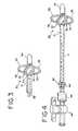
- FIG. 3is a perspective view of a Malecot catheter with an improved retention device
- FIG. 4depicts a kit using the improved retention device of FIG. 3 .
- embodiments of the inventionmay include Foley catheters, Foley feeding tubes, Rutner percutaneous balloon catheters, and so on.
- FIGS. 1 a and 1 bdepict an improved Foley catheter.
- FIG. 1 adepicts the catheter inflated or deployed, while FIG. 1 b depicts the catheter in a deflated state, ready for installation or removal.
- the improved Foley catheter 10includes a catheter tube 12 having a central lumen 12 a and one or more additional lumens 12 b .
- the catheterincludes a distal portion 12 connected via balloon 16 .
- Non-central lumen 12 cconnects the inside of balloon 16 to an outside source of saline or other fluid for inflation.
- Lumen 12 cmay be routed through tube 12 or in a separate tube alongside tube 12 , and is kept separate from central lumen (drainage line) 12 a .
- Catheter 10includes four superelastic wires 17 , such as Nitinol wires.
- the wiresextend from the proximal portion 13 through balloon 16 to the distal portion 14 of the catheter.
- the wiresare normally retained within lumens 12 b of tube 12 .
- the catheteris inserted into a desired location, such as into a bladder of a patient.
- the balloonis inflated, typically by pumping in a small amount, several ml, of saline or other sterile solution.
- the ballooninflates and is then retained within the bladder of the patient.
- the superelastic wires 17are partially pulled from lumens 12 b and extend distally from catheter tube 12 .
- the superelastic wiresno longer wholly retained within the tube, assume their relaxed position, as shown in FIG. 1 a , helping to inflate the balloon with the bends which the wires have previously been “trained” to assume.
- the wireshelp to expand the balloon and keep the balloon inflated even if a small amount of leakage occurs from the balloon.
- Another way to place the catheteris to insert an obturator 18 into the catheter, such that the distal tip of the obturator snugs against the distal tip 14 of the catheter, straightening the wires 17 and enabling the physician to place the catheter.
- the cathetermay be thus placed percutaneously or endoscopically.
- the obturatorcan be removed, thus allowing the wires 17 to assume their relaxed, expanded state, and allowing the catheter to function.
- the obturator 18may be used within central lumen 12 a to collapse the balloon.
- the balloonmay first be drained by applying a partial vacuum to the proximal end of lumen 12 c .
- the vacuum deviceis then removed, and an obturator, such as a sterile stainless steel obturator, is then carefully inserted into central lumen 12 a .
- Obturator 18is then advanced in the direction of arrow A in the manner shown in FIG. 1 b , causing the balloon to collapse and removing the retaining bends of the superelastic wires.
- the catheteris then ready for removal.
- An obturatormade from a polymeric material, such as plastic or PTFE, made be used instead.
- the wiresare desirably anchored near at least one end or the other of the balloon.
- a superelastic wire 27may be formed with a retention feature 27 a , 27 b at one or both ends.
- the wiresmay be molded into the distal end of the catheter or they may be molded into the catheter, located proximally of the balloon.
- the retention featurecauses the wire to remain in place when the balloon is inflated.
- other featuresmay be used, such as a tiny loop 27 b .
- these retention featuresWhen molded into a distal end of the catheter, or into the catheter at a point proximal of the proximal end of the balloon, these retention features will anchor the superelastic wire while allowing the shape change of the wire to help inflate the balloon.
- the wiresmay be looped around the distal end of the catheter.
- two of the wires 17 in FIG. 2may constitute a continuous loop around distal portion 14 of the catheter.
- the proximal ends of the wires of the loopextend into lumens 12 b as shown in FIG. 1 b .
- the distal end of the loopitself may be molded into the distal end of the catheter, anchoring the large loop to the distal end of the catheter in the same manner as the retention features discussed above, e.g., the small loop 27 b.
- the wiresmay be trained to assume the desired “bent” shape when they are partially pushed or pulled from lumens 12 b .
- the wires 17are preferably made of a superelastic or shape memory alloy, such as Nitinol, a nickel-titanium alloy.
- the wiresmay also be made from other shape memory metals, such as alloys of Cu—Zn—Al or Cu—Al—Ni.
- very thin wiresare preferred, such as wires having a diameter of about 0.0025 inches (about 0.063 mm).
- Round wiresare preferred, but wires of any shape may be used, including rectangular wire, square wire, wedge or “pie-shaped” wire, flat wire and triangular wire.
- the wiresmust have sufficient diameter to exert an adequate force upon the balloon or other device, in order to resist deflation and to assist in retaining the balloon or other device in its desired location within the patient.
- the wiresmay be formed into a desired shape and heat treated or “trained” into that shape by heating to a certain temperature for a certain length of time. Typically, temperatures in the range of 500-540° C. and times from 1-5 minutes are used. Other temperatures and times may also be used.
- Shape-memory or superelastic materialsare heat treated or annealed from a weak (martinsite) structure to a strong (austenite) structure. The alloys are weak and deformable in the martinsitic state, which is thus useful for forming the loops.
- the transformation temperatureis desirably a low temperature, well below the temperature of a human body, and preferably below room temperature, which is at least about 20-25° C.
- the transformation temperature of the wiresis thus selected to be well below the operating temperature of the catheter or other device to be retained within the body, thus keeping the wire in a superelastic state.
- the wiresadvantageously return to their original, unstressed shape when deforming stresses are removed.
- the superelastic wire alloyalso increasingly resists deformation as the stress load is increased. Thus, when a superelastic wire is collapsed and placed into the lumen 12 b , the wire is placed in a state of stress. When the wires are deployed, the stresses are removed, and the wires return to the desired bent shape.
- the bendsare formed by shaping the wires into the desired shape at room temperature or below, preferably with a cold mandrel, and then annealing the properly-shaped wires at the proper annealing temperature for a time sufficient for the transformation to a superelastic state.
- a bent wireis formed from 0.11 mm diameter (about 0.0043 inches) Ni—Ti Nitinol wire and is annealed at 990° F. (about 530° C.) for about 10 minutes. The time and temperature for annealing will vary with the alloy selected and with the diameter (thickness) of the wire.
- the wires themselvesmust remain at the desired temperature for the proper length of time for the annealing or heat-treatment to be complete. Proper annealing is very important for the wires to remain kink-free during deployment and operation of the catheter or other device. If kinks form for any reason, it may be difficult to deploy (expand) or retract the catheter or other device.
- the bendsare desirably formed before the annealing operation, as discussed above, including all wires or bends for a given catheter or other device.
- FIG. 2depicts a kit 20 or system that includes a Foley catheter 10 , connector 22 , tubing 23 , and stopcock 24 with connectors 25 .
- a one-way check valve 26may also be used to insure only one-way flow through central lumen 12 a .
- Catheter 10includes balloon 16 (shown inflated), superelastic wires 17 in their relaxed state, and distal portion 14 .
- Catheter 10may also include one or more orifices 19 for draining the bladder into which the catheter is placed.
- Other applications for improved Foley-type instrumentsmay include percutaneous suprapubic balloon catheters, urethrogram catheters, and gastrostomy feeding tubes.
- an improved Malecot catheter 30includes a catheter tube 31 one or more orifices 32 for drainage, and a distal end 34 connected to tube 32 by “wings” 33 .
- Wings 33include a superelastic wire 35 as described above, embedded within or on an inner surface of the wings, or at least one wing.
- Malecot catheter 30may also include an obturator 38 for holding the wings of the catheter in place until deployment is desired. The obturator is assembled in central lumen 31 a of the catheter, with the distal tip of obturator 38 just inside distal end 34 of the catheter. The Malecot is placed into the desired area, with the obturator held tightly to keep the wings in place.
- the obturatorWhen the obturator is removed, the superelastic wires assume their relaxed, bent shape, the wings deploy outward, and the Malecot is held in place. When the Malecot is to be removed, the process is reversed, again using an obturator or similar instrument to “fold” the wings and enable removal.
- Malecotsmay be part of a kit or system, as depicted in FIG. 4 .
- tube 31may be connected via connector 42 to a check valve 43 as desired, and via connector 44 to a valve 45 .
- Tube 31may include superelastic wires 17 .
- a Malecot-type devicemay be used, as mentioned above, for drainage or for feeding.
- Malecot-type devices with improved retention capabilitiesmay also be used for nephrostomy procedures, percutaneous procedures, and other medical procedures where improved retention is desired.
Landscapes
- Health & Medical Sciences (AREA)
- Life Sciences & Earth Sciences (AREA)
- Biophysics (AREA)
- Pulmonology (AREA)
- Engineering & Computer Science (AREA)
- Anesthesiology (AREA)
- Biomedical Technology (AREA)
- Heart & Thoracic Surgery (AREA)
- Hematology (AREA)
- Animal Behavior & Ethology (AREA)
- General Health & Medical Sciences (AREA)
- Public Health (AREA)
- Veterinary Medicine (AREA)
- Media Introduction/Drainage Providing Device (AREA)
Abstract
Description
Claims (14)
Priority Applications (1)
| Application Number | Priority Date | Filing Date | Title |
|---|---|---|---|
| US11/402,596US8177741B2 (en) | 2005-04-12 | 2006-04-12 | Catheter with superelastic retention device |
Applications Claiming Priority (2)
| Application Number | Priority Date | Filing Date | Title |
|---|---|---|---|
| US67050405P | 2005-04-12 | 2005-04-12 | |
| US11/402,596US8177741B2 (en) | 2005-04-12 | 2006-04-12 | Catheter with superelastic retention device |
Publications (2)
| Publication Number | Publication Date |
|---|---|
| US20060229553A1 US20060229553A1 (en) | 2006-10-12 |
| US8177741B2true US8177741B2 (en) | 2012-05-15 |
Family
ID=37084000
Family Applications (1)
| Application Number | Title | Priority Date | Filing Date |
|---|---|---|---|
| US11/402,596Expired - Fee RelatedUS8177741B2 (en) | 2005-04-12 | 2006-04-12 | Catheter with superelastic retention device |
Country Status (1)
| Country | Link |
|---|---|
| US (1) | US8177741B2 (en) |
Cited By (19)
| Publication number | Priority date | Publication date | Assignee | Title |
|---|---|---|---|---|
| US20110152912A1 (en)* | 2007-04-05 | 2011-06-23 | Boston Scientific Scimed, Inc. | Catheter Having Internal Mechanisms to Encourage Balloon Re-folding |
| US9149176B2 (en) | 2012-09-13 | 2015-10-06 | Emmy Medical, Llc | 4-way cystoscopy catheter |
| US9744331B2 (en) | 2015-07-20 | 2017-08-29 | Strataca Systems, LLC | Ureteral and bladder catheters and methods of inducing negative pressure to increase renal perfusion |
| US9950138B2 (en) | 2012-07-23 | 2018-04-24 | University Of Utah Research Foundation | Indwelling urinary catheter |
| US10118021B2 (en) | 2013-09-30 | 2018-11-06 | St. Jude Medical, Cardiology Division, Inc. | Catheter having an active return-to-straight mechanism |
| US10426919B2 (en) | 2015-07-20 | 2019-10-01 | Strataca Systems Limited | Systems and methods for inducing negative pressure in a portion of a urinary tract of a patient |
| US10512713B2 (en) | 2015-07-20 | 2019-12-24 | Strataca Systems Limited | Method of removing excess fluid from a patient with hemodilution |
| US10765834B2 (en) | 2015-07-20 | 2020-09-08 | Strataca Systems Limited | Ureteral and bladder catheters and methods of inducing negative pressure to increase renal perfusion |
| USD908865S1 (en) | 2018-08-17 | 2021-01-26 | Emmy Medical, Llc | Catheter |
| US10918827B2 (en) | 2015-07-20 | 2021-02-16 | Strataca Systems Limited | Catheter device and method for inducing negative pressure in a patient's bladder |
| US10926062B2 (en) | 2015-07-20 | 2021-02-23 | Strataca Systems Limited | Ureteral and bladder catheters and methods of inducing negative pressure to increase renal perfusion |
| US11040172B2 (en) | 2015-07-20 | 2021-06-22 | Strataca Systems Limited | Ureteral and bladder catheters and methods of inducing negative pressure to increase renal perfusion |
| US11040180B2 (en) | 2015-07-20 | 2021-06-22 | Strataca Systems Limited | Systems, kits and methods for inducing negative pressure to increase renal function |
| US11083874B2 (en) | 2018-01-24 | 2021-08-10 | Lotus Medical Technologies | Urinary catheter system with improved retaining structure and enhanced urinary drainage |
| US11229771B2 (en) | 2015-07-20 | 2022-01-25 | Roivios Limited | Percutaneous ureteral catheter |
| US11541205B2 (en) | 2015-07-20 | 2023-01-03 | Roivios Limited | Coated urinary catheter or ureteral stent and method |
| US11918762B2 (en) | 2018-10-03 | 2024-03-05 | St. Jude Medical, Cardiology Division, Inc. | Reduced actuation force electrophysiology catheter handle |
| US12059543B2 (en) | 2017-08-25 | 2024-08-13 | Roivios Limited | Indwelling pump for facilitating removal of urine from the urinary tract |
| US12064567B2 (en) | 2015-07-20 | 2024-08-20 | Roivios Limited | Percutaneous urinary catheter |
Families Citing this family (41)
| Publication number | Priority date | Publication date | Assignee | Title |
|---|---|---|---|---|
| US6391048B1 (en) | 2000-01-05 | 2002-05-21 | Integrated Vascular Systems, Inc. | Integrated vascular device with puncture site closure component and sealant and methods of use |
| US9579091B2 (en) | 2000-01-05 | 2017-02-28 | Integrated Vascular Systems, Inc. | Closure system and methods of use |
| US8758400B2 (en) | 2000-01-05 | 2014-06-24 | Integrated Vascular Systems, Inc. | Closure system and methods of use |
| DE60144328D1 (en) | 2000-09-08 | 2011-05-12 | Abbott Vascular Inc | Surgical clamp |
| US6626918B1 (en) | 2000-10-06 | 2003-09-30 | Medical Technology Group | Apparatus and methods for positioning a vascular sheath |
| US8690910B2 (en) | 2000-12-07 | 2014-04-08 | Integrated Vascular Systems, Inc. | Closure device and methods for making and using them |
| US6695867B2 (en) | 2002-02-21 | 2004-02-24 | Integrated Vascular Systems, Inc. | Plunger apparatus and methods for delivering a closure device |
| US6623510B2 (en) | 2000-12-07 | 2003-09-23 | Integrated Vascular Systems, Inc. | Closure device and methods for making and using them |
| IES20030424A2 (en) | 2002-06-04 | 2003-12-10 | Robert Stevenson | Blood vessel closure clip and delivery device |
| US8202293B2 (en) | 2003-01-30 | 2012-06-19 | Integrated Vascular Systems, Inc. | Clip applier and methods of use |
| US8398656B2 (en) | 2003-01-30 | 2013-03-19 | Integrated Vascular Systems, Inc. | Clip applier and methods of use |
| US8313497B2 (en) | 2005-07-01 | 2012-11-20 | Abbott Laboratories | Clip applier and methods of use |
| US20070255222A1 (en)* | 2006-03-27 | 2007-11-01 | Changqing Li | Catheter assembly including internal bolster |
| US8556930B2 (en) | 2006-06-28 | 2013-10-15 | Abbott Laboratories | Vessel closure device |
| WO2008027375A2 (en)* | 2006-08-31 | 2008-03-06 | Cook Incorporated | Rotationally actuated fixation mechanism |
| US8157765B2 (en)* | 2006-10-20 | 2012-04-17 | Boston Scientific Scimed, Inc. | Medical catheter assembly including a balloon bolster |
| US9282965B2 (en) | 2008-05-16 | 2016-03-15 | Abbott Laboratories | Apparatus and methods for engaging tissue |
| US8398676B2 (en) | 2008-10-30 | 2013-03-19 | Abbott Vascular Inc. | Closure device |
| US20110218568A1 (en)* | 2009-01-09 | 2011-09-08 | Voss Laveille K | Vessel closure devices, systems, and methods |
| US9414820B2 (en) | 2009-01-09 | 2016-08-16 | Abbott Vascular Inc. | Closure devices, systems, and methods |
| US9089311B2 (en) | 2009-01-09 | 2015-07-28 | Abbott Vascular Inc. | Vessel closure devices and methods |
| US9486191B2 (en) | 2009-01-09 | 2016-11-08 | Abbott Vascular, Inc. | Closure devices |
| US20100179589A1 (en) | 2009-01-09 | 2010-07-15 | Abbott Vascular Inc. | Rapidly eroding anchor |
| US9173644B2 (en) | 2009-01-09 | 2015-11-03 | Abbott Vascular Inc. | Closure devices, systems, and methods |
| US20100185234A1 (en) | 2009-01-16 | 2010-07-22 | Abbott Vascular Inc. | Closure devices, systems, and methods |
| KR101279583B1 (en)* | 2009-03-02 | 2013-06-27 | 김경태 | Suprapubic drainage urine catheter |
| US8801697B2 (en)* | 2009-04-20 | 2014-08-12 | Cheiron Japan Co. | Urination control device |
| US20110054492A1 (en) | 2009-08-26 | 2011-03-03 | Abbott Laboratories | Medical device for repairing a fistula |
| AU2012222114B2 (en) | 2011-02-25 | 2016-06-16 | Microvention, Inc. | Reinforced balloon catheter |
| JP2012249934A (en)* | 2011-06-06 | 2012-12-20 | Nihon Covidien Kk | Balloon type fistula catheter |
| US9332976B2 (en) | 2011-11-30 | 2016-05-10 | Abbott Cardiovascular Systems, Inc. | Tissue closure device |
| EP2614851B1 (en)* | 2012-01-16 | 2019-08-07 | Michael Tchirikov | Catheter |
| US9364209B2 (en) | 2012-12-21 | 2016-06-14 | Abbott Cardiovascular Systems, Inc. | Articulating suturing device |
| BR112017006558A2 (en) | 2014-09-30 | 2018-04-10 | sambusseti Antonio | orthotopic artificial bladder stent graft |
| JP6438574B2 (en)* | 2014-09-30 | 2018-12-12 | アントニオ・サンブッセティAntonio SAMBUSSETI | Orthotopic artificial endovesical prosthesis |
| US9724502B2 (en)* | 2015-07-10 | 2017-08-08 | Coloplast A/S | Dilator and method for penile prosthetic implantation |
| CN108136157A (en)* | 2015-07-20 | 2018-06-08 | 斯卓特凯系统有限责任公司 | Cause the conduit device and method of negative pressure in patient's bladder |
| US11957851B2 (en)* | 2017-04-10 | 2024-04-16 | Flat Medical Inc. | Catheter for guiding body fluid |
| US12097339B2 (en)* | 2019-12-31 | 2024-09-24 | Biosense Webster (Israel) Ltd. | System and methods of using a catheter with an anchoring mechanism |
| GB2594711A (en)* | 2020-05-04 | 2021-11-10 | Urologic Ltd | Catheter |
| US12156971B2 (en) | 2021-03-23 | 2024-12-03 | C. R. Bard, Inc. | Indwelling urinary catheter with guidewire anchoring mechanism |
Citations (34)
| Publication number | Priority date | Publication date | Assignee | Title |
|---|---|---|---|---|
| US2230226A (en)* | 1938-03-14 | 1941-02-04 | Davol Rubber Co | Catheter and its manufacture |
| US3915171A (en)* | 1974-06-06 | 1975-10-28 | Dennis William Shermeta | Gastrostomy tube |
| US4043338A (en)* | 1973-04-30 | 1977-08-23 | Ortho Pharmaceutical Corporation | Pharmaceutical formulation applicator device |
| US4921484A (en)* | 1988-07-25 | 1990-05-01 | Cordis Corporation | Mesh balloon catheter device |
| US5041093A (en)* | 1990-01-31 | 1991-08-20 | Boston Scientific Corp. | Catheter with foraminous anchor |
| US5318530A (en)* | 1991-12-06 | 1994-06-07 | Bissel Medical Products, Inc. | Gastrointestinal tube with inflatable bolus |
| US5336203A (en)* | 1993-05-28 | 1994-08-09 | Abbott Laboratories | Low profile gastrostomy device with dome |
| US5456251A (en)* | 1988-08-26 | 1995-10-10 | Mountpelier Investments, S.A. | Remote sensing tonometric catheter apparatus and method |
| US5842971A (en)* | 1996-05-22 | 1998-12-01 | Yoon; Inbae | Optical endoscopic portals and methods of using the same to establish passages through cavity walls |
| US5868708A (en)* | 1997-05-07 | 1999-02-09 | Applied Medical Resources Corporation | Balloon catheter apparatus and method |
| US5891113A (en)* | 1996-01-11 | 1999-04-06 | C. R. Bard, Inc. | Corporeal access tube assembly |
| US5906606A (en)* | 1995-12-04 | 1999-05-25 | Target Therapuetics, Inc. | Braided body balloon catheter |
| US5911702A (en)* | 1997-11-06 | 1999-06-15 | Heartport, Inc. | Methods and devices for cannulating a patient's blood vessel |
| US6033359A (en)* | 1997-10-28 | 2000-03-07 | Asahi Kogaku Kogyo Kabushiki Kaisha | Endoscopic length-measuring tool |
| US6176843B1 (en)* | 1998-12-09 | 2001-01-23 | Scimed Life Systems, Inc. | Catheter with distal manifold prep valve/manifold |
| US6569150B2 (en)* | 2000-04-11 | 2003-05-27 | Scimed Life Systems, Inc. | Reinforced retention structures |
| US6589208B2 (en)* | 2000-06-20 | 2003-07-08 | Applied Medical Resources Corporation | Self-deploying catheter assembly |
| US6629952B1 (en)* | 2000-12-29 | 2003-10-07 | Scimed Life Systems, Inc. | High pressure vascular balloon catheter |
| US6635068B1 (en)* | 1998-02-10 | 2003-10-21 | Artemis Medical, Inc. | Occlusion, anchoring, tensioning and flow direction apparatus and methods for use |
| US6709667B1 (en) | 1999-08-23 | 2004-03-23 | Conceptus, Inc. | Deployment actuation system for intrafallopian contraception |
| US20040087905A1 (en)* | 2001-07-17 | 2004-05-06 | Breznock Eugene M. | Method and apparatus for chest drainage |
| US6742545B2 (en)* | 1998-12-21 | 2004-06-01 | Parker-Hannifin Corporation | Hose construction |
| US6763833B1 (en) | 1999-08-23 | 2004-07-20 | Conceptus, Inc. | Insertion/deployment catheter system for intrafallopian contraception |
| US6764519B2 (en) | 2000-05-26 | 2004-07-20 | Scimed Life Systems, Inc. | Ureteral stent |
| US20050061771A1 (en)* | 2003-09-22 | 2005-03-24 | Scimed Life Systems, Inc. | Surface modified reinforcing member for medical device and method for making same |
| US20050090802A1 (en)* | 2003-04-28 | 2005-04-28 | Connors John J.Iii | Flexible sheath with varying durometer |
| US20050183729A1 (en)* | 2004-01-28 | 2005-08-25 | Fischer Frank J.Jr. | Dilational device having a reinforced balloon catheter |
| US6982024B2 (en)* | 2000-01-19 | 2006-01-03 | Boris Shkolnik | Inflatable balloon catheter seal and method |
| US20060061771A1 (en)* | 2003-06-19 | 2006-03-23 | Hill Henry A | Compensation for effects of beam misalignments in interferometer metrology systems |
| US20060074308A1 (en)* | 2004-09-28 | 2006-04-06 | Nasser Rafiee | Catheter with curved distal section having reinforcing strip and method of making same |
| US7070587B2 (en)* | 1999-02-24 | 2006-07-04 | Sherwood Services Ag | Securing device for a low profile gastrostomy tube having an inflatable balloon |
| US7070578B2 (en)* | 2002-04-25 | 2006-07-04 | Alcon, Inc. | Surgical cassette latching mechanism |
| US7625361B2 (en)* | 2003-04-28 | 2009-12-01 | Sumitomo Bakelite Company Limited | Catheter kit for burrow |
| US7862577B2 (en)* | 1997-11-03 | 2011-01-04 | C. R. Bard, Inc. | Temporary vascular filter guide wire |
- 2006
- 2006-04-12USUS11/402,596patent/US8177741B2/ennot_activeExpired - Fee Related
Patent Citations (34)
| Publication number | Priority date | Publication date | Assignee | Title |
|---|---|---|---|---|
| US2230226A (en)* | 1938-03-14 | 1941-02-04 | Davol Rubber Co | Catheter and its manufacture |
| US4043338A (en)* | 1973-04-30 | 1977-08-23 | Ortho Pharmaceutical Corporation | Pharmaceutical formulation applicator device |
| US3915171A (en)* | 1974-06-06 | 1975-10-28 | Dennis William Shermeta | Gastrostomy tube |
| US4921484A (en)* | 1988-07-25 | 1990-05-01 | Cordis Corporation | Mesh balloon catheter device |
| US5456251A (en)* | 1988-08-26 | 1995-10-10 | Mountpelier Investments, S.A. | Remote sensing tonometric catheter apparatus and method |
| US5041093A (en)* | 1990-01-31 | 1991-08-20 | Boston Scientific Corp. | Catheter with foraminous anchor |
| US5318530A (en)* | 1991-12-06 | 1994-06-07 | Bissel Medical Products, Inc. | Gastrointestinal tube with inflatable bolus |
| US5336203A (en)* | 1993-05-28 | 1994-08-09 | Abbott Laboratories | Low profile gastrostomy device with dome |
| US5906606A (en)* | 1995-12-04 | 1999-05-25 | Target Therapuetics, Inc. | Braided body balloon catheter |
| US5891113A (en)* | 1996-01-11 | 1999-04-06 | C. R. Bard, Inc. | Corporeal access tube assembly |
| US5842971A (en)* | 1996-05-22 | 1998-12-01 | Yoon; Inbae | Optical endoscopic portals and methods of using the same to establish passages through cavity walls |
| US5868708A (en)* | 1997-05-07 | 1999-02-09 | Applied Medical Resources Corporation | Balloon catheter apparatus and method |
| US6033359A (en)* | 1997-10-28 | 2000-03-07 | Asahi Kogaku Kogyo Kabushiki Kaisha | Endoscopic length-measuring tool |
| US7862577B2 (en)* | 1997-11-03 | 2011-01-04 | C. R. Bard, Inc. | Temporary vascular filter guide wire |
| US5911702A (en)* | 1997-11-06 | 1999-06-15 | Heartport, Inc. | Methods and devices for cannulating a patient's blood vessel |
| US6635068B1 (en)* | 1998-02-10 | 2003-10-21 | Artemis Medical, Inc. | Occlusion, anchoring, tensioning and flow direction apparatus and methods for use |
| US6176843B1 (en)* | 1998-12-09 | 2001-01-23 | Scimed Life Systems, Inc. | Catheter with distal manifold prep valve/manifold |
| US6742545B2 (en)* | 1998-12-21 | 2004-06-01 | Parker-Hannifin Corporation | Hose construction |
| US7070587B2 (en)* | 1999-02-24 | 2006-07-04 | Sherwood Services Ag | Securing device for a low profile gastrostomy tube having an inflatable balloon |
| US6709667B1 (en) | 1999-08-23 | 2004-03-23 | Conceptus, Inc. | Deployment actuation system for intrafallopian contraception |
| US6763833B1 (en) | 1999-08-23 | 2004-07-20 | Conceptus, Inc. | Insertion/deployment catheter system for intrafallopian contraception |
| US6982024B2 (en)* | 2000-01-19 | 2006-01-03 | Boris Shkolnik | Inflatable balloon catheter seal and method |
| US6569150B2 (en)* | 2000-04-11 | 2003-05-27 | Scimed Life Systems, Inc. | Reinforced retention structures |
| US6764519B2 (en) | 2000-05-26 | 2004-07-20 | Scimed Life Systems, Inc. | Ureteral stent |
| US6589208B2 (en)* | 2000-06-20 | 2003-07-08 | Applied Medical Resources Corporation | Self-deploying catheter assembly |
| US6629952B1 (en)* | 2000-12-29 | 2003-10-07 | Scimed Life Systems, Inc. | High pressure vascular balloon catheter |
| US20040087905A1 (en)* | 2001-07-17 | 2004-05-06 | Breznock Eugene M. | Method and apparatus for chest drainage |
| US7070578B2 (en)* | 2002-04-25 | 2006-07-04 | Alcon, Inc. | Surgical cassette latching mechanism |
| US20050090802A1 (en)* | 2003-04-28 | 2005-04-28 | Connors John J.Iii | Flexible sheath with varying durometer |
| US7625361B2 (en)* | 2003-04-28 | 2009-12-01 | Sumitomo Bakelite Company Limited | Catheter kit for burrow |
| US20060061771A1 (en)* | 2003-06-19 | 2006-03-23 | Hill Henry A | Compensation for effects of beam misalignments in interferometer metrology systems |
| US20050061771A1 (en)* | 2003-09-22 | 2005-03-24 | Scimed Life Systems, Inc. | Surface modified reinforcing member for medical device and method for making same |
| US20050183729A1 (en)* | 2004-01-28 | 2005-08-25 | Fischer Frank J.Jr. | Dilational device having a reinforced balloon catheter |
| US20060074308A1 (en)* | 2004-09-28 | 2006-04-06 | Nasser Rafiee | Catheter with curved distal section having reinforcing strip and method of making same |
Cited By (42)
| Publication number | Priority date | Publication date | Assignee | Title |
|---|---|---|---|---|
| US20110152912A1 (en)* | 2007-04-05 | 2011-06-23 | Boston Scientific Scimed, Inc. | Catheter Having Internal Mechanisms to Encourage Balloon Re-folding |
| US9950138B2 (en) | 2012-07-23 | 2018-04-24 | University Of Utah Research Foundation | Indwelling urinary catheter |
| US10376137B2 (en) | 2012-09-13 | 2019-08-13 | Emmy Medical, Llc | Indwelling bladder catheter |
| US9149176B2 (en) | 2012-09-13 | 2015-10-06 | Emmy Medical, Llc | 4-way cystoscopy catheter |
| US10118021B2 (en) | 2013-09-30 | 2018-11-06 | St. Jude Medical, Cardiology Division, Inc. | Catheter having an active return-to-straight mechanism |
| US10898686B2 (en) | 2013-09-30 | 2021-01-26 | St. Jude Medical, Cardiology Division, Inc. | Catheter having an active return-to-straight mechanism |
| US11077284B2 (en) | 2015-07-20 | 2021-08-03 | Strataca Systems Limited | Ureteral and bladder catheters and methods of inducing negative pressure to increase renal perfusion |
| US11229771B2 (en) | 2015-07-20 | 2022-01-25 | Roivios Limited | Percutaneous ureteral catheter |
| US10493232B2 (en) | 2015-07-20 | 2019-12-03 | Strataca Systems Limited | Ureteral catheters, bladder catheters, systems, kits and methods for inducing negative pressure to increase renal function |
| US10512713B2 (en) | 2015-07-20 | 2019-12-24 | Strataca Systems Limited | Method of removing excess fluid from a patient with hemodilution |
| US10610664B2 (en) | 2015-07-20 | 2020-04-07 | Strataca Systems Limited | Ureteral and bladder catheters and methods of inducing negative pressure to increase renal perfusion |
| US10765834B2 (en) | 2015-07-20 | 2020-09-08 | Strataca Systems Limited | Ureteral and bladder catheters and methods of inducing negative pressure to increase renal perfusion |
| US10799668B2 (en) | 2015-07-20 | 2020-10-13 | Strataca Systems Limited | Ureteral catheters, bladder catheters, systems, kits and methods for inducing negative pressure to increase renal function |
| US12364845B2 (en) | 2015-07-20 | 2025-07-22 | Roivios Limited | Pump, system and methods of inducing negative pressure to increase renal perfusion |
| US10307564B2 (en) | 2015-07-20 | 2019-06-04 | Strataca Systems Limited | Ureteral and bladder catheters and methods of inducing negative pressure to increase renal perfusion |
| US10918827B2 (en) | 2015-07-20 | 2021-02-16 | Strataca Systems Limited | Catheter device and method for inducing negative pressure in a patient's bladder |
| US10918825B2 (en) | 2015-07-20 | 2021-02-16 | Strataca Systems Limited | Ureteral and bladder catheters and methods of inducing negative pressure to increase renal perfusion |
| US10926062B2 (en) | 2015-07-20 | 2021-02-23 | Strataca Systems Limited | Ureteral and bladder catheters and methods of inducing negative pressure to increase renal perfusion |
| US11040172B2 (en) | 2015-07-20 | 2021-06-22 | Strataca Systems Limited | Ureteral and bladder catheters and methods of inducing negative pressure to increase renal perfusion |
| US11040180B2 (en) | 2015-07-20 | 2021-06-22 | Strataca Systems Limited | Systems, kits and methods for inducing negative pressure to increase renal function |
| US9744331B2 (en) | 2015-07-20 | 2017-08-29 | Strataca Systems, LLC | Ureteral and bladder catheters and methods of inducing negative pressure to increase renal perfusion |
| US12357793B2 (en) | 2015-07-20 | 2025-07-15 | Roivios Limited | Ureteral and bladder catheters and methods of inducing negative pressure to increase renal perfusion |
| US12274832B2 (en) | 2015-07-20 | 2025-04-15 | Roivios Limited | Percutaneous urinary catheter |
| US10426919B2 (en) | 2015-07-20 | 2019-10-01 | Strataca Systems Limited | Systems and methods for inducing negative pressure in a portion of a urinary tract of a patient |
| US11420014B2 (en) | 2015-07-20 | 2022-08-23 | Roivios Limited | Ureteral and bladder catheters and methods of inducing negative pressure to increase renal perfusion |
| US11471583B2 (en) | 2015-07-20 | 2022-10-18 | Roivios Limited | Method of removing excess fluid from a patient with hemodilution |
| US11541205B2 (en) | 2015-07-20 | 2023-01-03 | Roivios Limited | Coated urinary catheter or ureteral stent and method |
| US11612714B2 (en) | 2015-07-20 | 2023-03-28 | Roivios Limited | Systems and methods for inducing negative pressure in a portion of a urinary tract of a patient |
| US11752300B2 (en) | 2015-07-20 | 2023-09-12 | Roivios Limited | Catheter device and method for inducing negative pressure in a patient's bladder |
| US11896785B2 (en) | 2015-07-20 | 2024-02-13 | Roivios Limited | Ureteral and bladder catheters and methods of inducing negative pressure to increase renal perfusion |
| US11904113B2 (en) | 2015-07-20 | 2024-02-20 | Roivios Limited | Ureteral and bladder catheters and methods of inducing negative pressure to increase renal perfusion |
| US11904121B2 (en) | 2015-07-20 | 2024-02-20 | Roivios Limited | Negative pressure therapy system |
| US11918754B2 (en) | 2015-07-20 | 2024-03-05 | Roivios Limited | Ureteral and bladder catheters and methods of inducing negative pressure to increase renal perfusion |
| US12226594B2 (en) | 2015-07-20 | 2025-02-18 | Roivios Limited | Percutaneous urinary catheter |
| US12023459B2 (en) | 2015-07-20 | 2024-07-02 | Roivios Limited | Negative pressure therapy system |
| US12076225B2 (en) | 2015-07-20 | 2024-09-03 | Roivios Limited | Ureteral catheters, bladder catheters, systems, kits and methods for inducing negative pressure to increase renal function |
| US12064567B2 (en) | 2015-07-20 | 2024-08-20 | Roivios Limited | Percutaneous urinary catheter |
| US12059543B2 (en) | 2017-08-25 | 2024-08-13 | Roivios Limited | Indwelling pump for facilitating removal of urine from the urinary tract |
| US11083874B2 (en) | 2018-01-24 | 2021-08-10 | Lotus Medical Technologies | Urinary catheter system with improved retaining structure and enhanced urinary drainage |
| USD935013S1 (en) | 2018-08-17 | 2021-11-02 | Emmy Medical, Llc | Catheter |
| USD908865S1 (en) | 2018-08-17 | 2021-01-26 | Emmy Medical, Llc | Catheter |
| US11918762B2 (en) | 2018-10-03 | 2024-03-05 | St. Jude Medical, Cardiology Division, Inc. | Reduced actuation force electrophysiology catheter handle |
Also Published As
| Publication number | Publication date |
|---|---|
| US20060229553A1 (en) | 2006-10-12 |
Similar Documents
| Publication | Publication Date | Title |
|---|---|---|
| US8177741B2 (en) | Catheter with superelastic retention device | |
| US10130347B2 (en) | Hemostasis-enhancing device and method for its use | |
| US5466242A (en) | Stent for biliary, urinary or vascular system | |
| JP4940390B2 (en) | Medical device having knitted structure and coil | |
| JP4771425B2 (en) | Stent | |
| US8057503B2 (en) | Blood vessel occluder and method of use | |
| EP2756821B1 (en) | Vascular implant | |
| EP1389073B1 (en) | Draining bodily fluids with a stent | |
| US6790223B2 (en) | Delivering a uretheral stent | |
| US20090210045A1 (en) | Stent | |
| EP0380666A1 (en) | Tool for securing inner diameter of inner cavity of tubular organ | |
| CN106794334A (en) | Ureter bracket | |
| JP2006521877A (en) | Self-positionable catheter assembly | |
| JP2009513200A (en) | Stent having a fixed portion | |
| EP2222364A2 (en) | Biliary shunts, delivery systems, methods of using the same, and kits therefor | |
| US20090112183A1 (en) | Medical devices and methods of use | |
| JP2001500030A (en) | Device for maintaining urinary bowel depression | |
| JP2009543660A (en) | Nipple dilator | |
| US20230329722A1 (en) | Left atrial appendage occlusion methods and devices | |
| WO2007027216A2 (en) | Foley catheter adaptor | |
| US20120150193A1 (en) | System and methods for hysteroscopic tubular ligation | |
| WO2023076162A1 (en) | Atraumatic catheter | |
| US20240423635A1 (en) | Left atrial appendage occlusion methods and devices | |
| EP2620129B1 (en) | The system for introducing and positioning of a stent, in particular an intestinal stent. | |
| JP2539955B2 (en) | A catheter equipped with a device for securing the inner diameter of the lumen of a tubular organ |
Legal Events
| Date | Code | Title | Description |
|---|---|---|---|
| AS | Assignment | Owner name:VANCE PRODUCTS INCORPORATED, D/B/A COOK UROLOGICAL Free format text:ASSIGNMENT OF ASSIGNORS INTEREST;ASSIGNORS:HAMMACK, ANTHONY D.;WILLIS, TRACY E.;REEL/FRAME:017784/0540 Effective date:20060411 | |
| ZAAA | Notice of allowance and fees due | Free format text:ORIGINAL CODE: NOA | |
| ZAAB | Notice of allowance mailed | Free format text:ORIGINAL CODE: MN/=. | |
| AS | Assignment | Owner name:COOK MEDICAL TECHNOLOGIES LLC, INDIANA Free format text:ASSIGNMENT OF ASSIGNORS INTEREST;ASSIGNOR:COOK INCORPORATED;REEL/FRAME:027937/0277 Effective date:20120323 | |
| STCF | Information on status: patent grant | Free format text:PATENTED CASE | |
| FPAY | Fee payment | Year of fee payment:4 | |
| MAFP | Maintenance fee payment | Free format text:PAYMENT OF MAINTENANCE FEE, 8TH YEAR, LARGE ENTITY (ORIGINAL EVENT CODE: M1552); ENTITY STATUS OF PATENT OWNER: LARGE ENTITY Year of fee payment:8 | |
| FEPP | Fee payment procedure | Free format text:MAINTENANCE FEE REMINDER MAILED (ORIGINAL EVENT CODE: REM.); ENTITY STATUS OF PATENT OWNER: LARGE ENTITY | |
| AS | Assignment | Owner name:WILMINGTON TRUST, NATIONAL ASSOCIATION, AS COLLATERAL AGENT, DELAWARE Free format text:SECURITY INTEREST;ASSIGNOR:COOK MEDICAL TECHNOLOGIES LLC;REEL/FRAME:066700/0277 Effective date:20240227 | |
| LAPS | Lapse for failure to pay maintenance fees | Free format text:PATENT EXPIRED FOR FAILURE TO PAY MAINTENANCE FEES (ORIGINAL EVENT CODE: EXP.); ENTITY STATUS OF PATENT OWNER: LARGE ENTITY | |
| STCH | Information on status: patent discontinuation | Free format text:PATENT EXPIRED DUE TO NONPAYMENT OF MAINTENANCE FEES UNDER 37 CFR 1.362 | |
| FP | Lapsed due to failure to pay maintenance fee | Effective date:20240515 |