US8176844B2 - Heated humidified food cabinet - Google Patents
Heated humidified food cabinetDownload PDFInfo
- Publication number
- US8176844B2 US8176844B2US12/359,625US35962509AUS8176844B2US 8176844 B2US8176844 B2US 8176844B2US 35962509 AUS35962509 AUS 35962509AUS 8176844 B2US8176844 B2US 8176844B2
- Authority
- US
- United States
- Prior art keywords
- container
- air
- cabinet
- food
- water
- Prior art date
- Legal status (The legal status is an assumption and is not a legal conclusion. Google has not performed a legal analysis and makes no representation as to the accuracy of the status listed.)
- Active, expires
Links
- 235000013305foodNutrition0.000titleclaimsabstractdescription82
- XLYOFNOQVPJJNP-UHFFFAOYSA-NwaterSubstancesOXLYOFNOQVPJJNP-UHFFFAOYSA-N0.000claimsabstractdescription85
- 238000010438heat treatmentMethods0.000claimsabstractdescription65
- 230000003750conditioning effectEffects0.000claimsdescription8
- 238000004378air conditioningMethods0.000claimsdescription7
- 230000001143conditioned effectEffects0.000description3
- 238000004140cleaningMethods0.000description2
- 230000000694effectsEffects0.000description2
- 238000009434installationMethods0.000description2
- 230000002452interceptive effectEffects0.000description2
- 230000004048modificationEffects0.000description2
- 238000012986modificationMethods0.000description2
- 230000004075alterationEffects0.000description1
- 230000000903blocking effectEffects0.000description1
- 238000010586diagramMethods0.000description1
- 230000008020evaporationEffects0.000description1
- 238000001704evaporationMethods0.000description1
- 239000004519greaseSubstances0.000description1
- 239000008236heating waterSubstances0.000description1
- 239000000463materialSubstances0.000description1
- 239000002245particleSubstances0.000description1
- 230000007704transitionEffects0.000description1
- 230000000007visual effectEffects0.000description1
Images


Classifications
- A—HUMAN NECESSITIES
- A47—FURNITURE; DOMESTIC ARTICLES OR APPLIANCES; COFFEE MILLS; SPICE MILLS; SUCTION CLEANERS IN GENERAL
- A47J—KITCHEN EQUIPMENT; COFFEE MILLS; SPICE MILLS; APPARATUS FOR MAKING BEVERAGES
- A47J39/00—Heat-insulated warming chambers; Cupboards with heating arrangements for warming kitchen utensils
- A47J39/003—Heat-insulated warming chambers; Cupboards with heating arrangements for warming kitchen utensils with forced air circulation
- A—HUMAN NECESSITIES
- A47—FURNITURE; DOMESTIC ARTICLES OR APPLIANCES; COFFEE MILLS; SPICE MILLS; SUCTION CLEANERS IN GENERAL
- A47J—KITCHEN EQUIPMENT; COFFEE MILLS; SPICE MILLS; APPARATUS FOR MAKING BEVERAGES
- A47J27/00—Cooking-vessels
- A47J27/14—Cooking-vessels for use in hotels, restaurants, or canteens
- A47J27/16—Cooking-vessels for use in hotels, restaurants, or canteens heated by steam
Definitions
- the present inventionrelates to food containers or cabinets in which the air is conditioned to permit storage of prepared foods in the cabinet until the foods are ready to be served or eaten.
- Food cabinets of this typeare typically heated or heated and humidified, with the air in the cabinets being circulated to maintain a consistency in the environment within the food container.
- heating elementsare used for heating the air and heating water to increase the temperature and humidity within the cabinet.
- such cabinetsare provided with a standard 110-120 V power connection so that they can be connected to a regular wall socket power supply in a restaurant, dining hall, cafeteria, or similar location.
- power suppliesare protected by 15 or 20 amp circuit breakers.
- the heating elementsare capable of being operated simultaneously, which limits the total wattage of the heating elements to 2000 W. Since the heating elements may operate simultaneously, typically each of the heating elements is limited to a size of 1000 W.
- Food cabinets that provide heat and humidityinclude controls that accept inputs from temperature sensors and humidity sensors in order to operate the heating elements and air blowers to heat, humidify and move the air within the cabinet to achieve a desired temperature and humidity as selected by a user of the equipment.
- Such controlsare typically preset at the factory with control software which cannot be modified or updated in the field, without removal and replacement of hardware components, such as integrated circuits and memory modules, which requires a qualified service technician.
- All food cabinetsinclude a power cord connection to provide electrical power to the various components in the food cabinet.
- the power cordexits from the cabinet though a rear wall or a side wall of the cabinet.
- the cabinetsare mobile and they may be moved into different locations in a room. Other times the cabinets are stationary, however they may be placed in varying locations relative to walls and power outlets.
- the power cord connectionbeing located at a fixed location on the cabinet, the cord is sometimes interfering with the placement of the cabinet against a wall or in a corner since the protrusion of the cord from the wall of the cabinet prevents the cabinet from being pressed flush up against the wall.
- a food containerhaving walls defining an exterior of the container and an open interior for receiving food items. At least one opening in the walls provides access to move food items into and out of the interior of the container.
- An air moving devicecreates a moving air stream.
- Ductworkis configured to circulate the air stream in the container. The ductwork is configured to direct at least a portion of the air stream through the interior of the container adjacent to the food items.
- An air heating elementis located in the air stream.
- a water receptaclereceives a supply of water. The ductwork is configured to direct at least a portion of the air stream over the supply of water.
- a water heating elementis arranged to add heat energy to the supply of water in the water receptacle.
- a controlis arranged to operate the air and water heating elements alternately and not simultaneously.
- a food containerhaving walls defining an exterior of the container and an open interior for receiving food items. At least one opening in the walls provides access to move food items into and out of the interior of the container.
- An air moving devicecreates a moving air stream.
- Ductworkis configured to circulate the air stream in the container. The ductwork is configured to direct at least a portion of the air stream through the interior of the container adjacent to the food items.
- An air heating elementis located in the air stream.
- a water receptaclereceives a supply of water. The ductwork is configured to direct at least a portion of the air stream over the supply of water.
- a water heating elementis arranged to add heat energy to the supply of water in the water receptacle.
- a controlis arranged to control the temperature and humidity within the cabinet.
- the controlincludes a microprocessor and a digital storage device for storing instructions for the microprocessor.
- An interfaceis provided at an exterior of the cabinet via which electronic signals can be directed to or received from the microprocessor or digital storage device.
- a food conditioning containerin an embodiment of the invention, includes walls defining an exterior of the container and an open interior for receiving food items. At least one opening in the walls provides access to move food items into and out of the interior of the container. At least one electrically operated air conditioning element is positioned within the cabinet to condition at least one characteristic of the air. A power cord extends to the exterior of the cabinet and exiting from the cabinet at a corner of a side wall, the top wall and the back wall.
- the containermay be provided with a removable water receptacle and a water heating element positioned within the receptacle.
- the water heating elementmay be mounted in a pivotable fashion such that as the receptacle is removed from the container, the heating element is automatically pivoted out from within the receptacle and as the receptacle is returned to the container, the heating element is automatically pivoted into the receptacle.
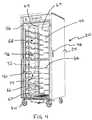
- FIG. 1is a left side perspective view of a food cabinet embodying the principles of the present invention.
- FIG. 2is a right side perspective view of the food cabinet embodying the principles of the present invention.
- FIG. 3is a front left perspective view of the food cabinet with the front doors removed.
- FIG. 4is a front right perspective view of the food cabinet with the front doors removed.
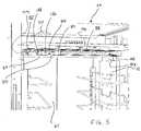
- FIG. 5is a partial, front perspective view of an area of the food cabinet above the ceiling.
- FIG. 6is a partial side perspective view of an upper portion of interior of the food cabinet.
- FIG. 7is a partial side perspective view of an upper portion of interior of the food cabinet.
- FIG. 8is a top view of the area above the ceiling of the food cabinet.
- FIG. 9is a side view of a lower portion of the food cabinet.
- FIG. 10is a top down perspective view of the floor of the food cabinet.
- FIG. 11is a top down perspective view of the floor of the food cabinet with a cover plate removed.
- FIG. 12is a bottom up perspective view of the bottom of the food cabinet with a portion of the water receptacle removed.
- FIG. 13is a bottom up perspective partial view of the bottom of the food cabinet with the water receptacle completely removed.
- FIG. 14is an isolated perspective side view of the water heating element mounting bar.
- FIG. 15is a front view of a control panel area of the food cabinet.
- FIG. 16is a schematic diagram of the control for the food cabinet.
- FIG. 17is a top view of a corner of the food cabinet showing the installation of the power cord.
- FIG. 18is a side perspective view of the corner of the food cabinet showing the installation of the power cord.
- FIGS. 1 and 2An embodiment of the invention is illustrated in the FIGs. although the present invention can take the form of other embodiments which may vary from the one illustrated.
- a food container or cabinet 20is shown having a left side wall 22 , a right side wall 24 , a top wall 26 , a rear wall 28 , a bottom wall 30 and a front wall 32 defining an exterior 34 of the container.
- the front wall 32is shown as having two openable doors 36 , 38 , which normally close at least one opening 40 ( FIGS. 3 and 4 ) in the walls which provides access to an open interior 42 for receiving food items.
- the doors 36 , 38food items may be moved into and out of the interior 42 of the cabinet.
- the cabinet 20may be provided with wheels or casters 44 as illustrated to allow for the cabinet to be easily movable, or it may have fixed feet if the cabinet is to remain stationary. If the cabinet 20 is provided with wheels 44 , it may also have finger grip recesses 46 on the side walls 22 , 24 , to permit a user to easily grasp and move the cabinet.
- the doors 36 , 38are provided with handles 48 along one edge 50 and hinges 52 along an opposite edge 54 to allow the doors to be opened to provide access to the interior 42 .
- a rear wall 60In the interior 42 there are provided inside side walls, 56 , 58 a rear wall 60 , a floor 62 and a ceiling 64 . In those cabinets where the doors 36 , 38 do not comprise the entire front wall 32 , there may also be an interior front wall.
- support elements 66in the form of brackets secured to the interior side walls 56 , 58 for receiving trays or shelves upon which the food items may be placed. In other embodiments, actual shelves, preferably with air openings therethrough, may be secured to the side walls 56 , 58 , or other types of support elements may be provided.
- the shelves or trays, as well as the brackets 66may be removable and adjustable, so as to accommodate various types of food support members.
- the cabinet 20includes at least one element for conditioning the air within the interior 42 of the cabinet.
- one characteristic of the air that may be conditionedis the stationary or moving condition of the air, so there may be an air circulation system which includes ductwork 68 and an air moving device 70 such as a blower or fan ( FIGS. 5 and 8 ).
- the ductwork 68includes a channel 72 defining an air passage arranged vertically along a central portion 74 of each interior side wall 56 , 58 , extending from the floor 62 to the ceiling 64 .
- the channels 72are provided with air holes 76 along a height of the channels which permit air to flow out of and into the air passages defined by the channels, depending on the relative air pressure within the channels and in the interior 42 of the cabinet 20 .
- the air passages defined by the channels 72extend through the ceiling 64 into a plenum 77 located above the ceiling.
- the plenum 77is divided into an upper chamber 78 and a lower chamber 80 by a horizontal wall 82 .
- the air passages from the channels 72communicate with the lower chamber 80 by means of transition ducts 83 ( FIGS. 6 and 7 ).
- the lower chamber 80includes an opening 84 ( FIG. 5 ) in the horizontal wall 82 which leads to the inlet of the air moving device 70 .
- the air moving devicepressurizes the air and causes an air stream to move in the upper chamber 78 towards and through an opening 86 leading to a second lower chamber 85 formed by an enclosure 87 mounted to an underside of the horizontal wall 82 .
- an air heating element 88Positioned at least partially in the opening 86 is an air heating element 88 which can be energized to heat the air in the air stream flowing into the second lower chamber 85 .
- the air heating element 88comprises another air conditioning element.
- the heating element 88may be rated at 2000 W, 110-120 V. In other markets where 220-240 V is a more prevalent power supply, the heating element 88 may be designed to operate at those voltages.
- the enclosure 87prevents the air stream coming from the upper chamber 78 from flowing back into the inlet opening 84 leading to the air moving device 70 , and therefore the air stream from the air moving device flows into the air passage behind the channel 72 on the right side interior wall 58 .
- This pressurized airflows through the various air holes 76 in the channel 72 so that the air flows into the cabinet interior 42 at points all along the height of the side wall 58 .
- the air passage behind the channel 72 on the left side interior wall 56communicates directly with the inlet opening 84 leading to the air moving device 70 , and therefore the pressure in that air passage is lower than in the cabinet interior 42 , causing air to flow into the air passage through the air holes 76 in the left side channel 72 .
- the ductwork 68is configured to circulate the air stream in the interior 42 of the cabinet 20 and to direct at least a portion of the air stream through the interior of the cabinet adjacent to the food items stored in the cabinet.
- air holes 76By having the air holes 76 positioned all along the height of the cabinet 20 , air flow is assured within the cabinet, even if the food items on one or more shelves are blocking the air holes at the level of that shelf. The air will continue to flow out of the other air holes 76 to maintain the heat and humidity at the desired levels throughout the cabinet 20 .
- the cross flow of air from one side interior wall 58 to the other side wall 56assures that the air flow within the cabinet 20 is primarily parallel to the door opening 40 of the cabinet, thereby creating an air curtain at the opening and substantially preventing a loss of heat from the interior of the cabinet.
- a water receptacle 92( FIG. 9 ) is provided for receiving a supply of water.
- the receptacle 92is located below the floor 62 of the cabinet 20 , and an opening 94 is provided in the floor to allow evaporated water to be picked up by the air flowing through the interior 42 of the cabinet since the air flow within the cabinet will be directed in a generally horizontal manner above the receptacle.
- a water heating element 95is arranged to add heat energy to the water ( FIGS. 9 and 11 ).
- This water heating element 95comprises another air conditioning element since it is used to increase the humidity characteristic of the air in the cabinet 20 .
- the water heating element 95extends down into the receptacle 92 such that it would be immersed in the supply of water in the receptacle.
- the water heating element 95could be positioned below or adjacent to, or formed in the walls of the receptacle 92 .
- the heating element 95may be rated at 2000 W, 110-120 V. In other markets where 220-240 V is a more prevalent power supply, the heating element 95 may operate at those voltages.
- the opening 94 in the floor 62 of the cabinet 20may be provided with a cover plate 96 ( FIG. 10 ) which is perforated with large enough holes 98 to permit water vapor to flow up through the cover plate, yet to prevent a person from extending their fingers through the holes, and to prevent other large objects from falling through the opening 94 so that the objects will not inadvertently touch the water heating element 94 , particularly when it is hot.
- the cover plate 96may also be provided with a much larger opening 100 to allow for easy filling of the receptacle 92 with water, such as from a separate container or hose.
- a portion 101 of the cover plate 96 which is removed to create the opening 100may be folded down into the receptacle 92 as a guard against backsplash of water as it is being poured into the receptacle 92 and to prevent direct access to the water heating element 95 through the opening 100 .
- the water receptacle 92may be removed from the cabinet 20 for ease in cleaning of the receptacle in the event that small food particles and other debris fall into the receptacle.
- the receptacle 92is slidably mounted on rails 102 ( FIG. 12 ) and may easily be removed by removing the cover plate 96 and then first sliding a condensate pan 103 out for disposal of any collected condensate, and then sliding the receptacle out for cleaning and then replacement.
- a back wall 104engages a flange 105 on a depending panel 106 ( FIGS.
- the heating element 95is pivoted up and out of the way of the walls of the receptacle 92 to an over-center position automatically and remains in this elevated, over-center position until the receptacle is replaced.
- the back wall 104engages an angled back wall 111 of the mounting bar 108 , which was pivoted into a position behind and below the top of the receptacle back wall 104 when the receptacle was removed.
- the engagement of the receptacle back wall 104 with the mounting bar back wall 111causes the mounting bar to pivot back to the initial position, as shown in FIG. 9 , with the water heating element 95 returned to a position within the receptacle.
- the pivoting action of the water heating element 95occurs automatically upon the removal and replacement of the receptacle 92 , and therefore the user does not need to take any additional steps to move the water heating element out of the way to effect removal of the receptacle nor to effect replacement of the receptacle.
- a stop 112( FIG. 13 ) is provided to engage the receptacle 92 when it is returned to its operating position.
- a limit switch 114is also provided to prevent the heating element 95 from being energized if the receptacle 92 is not replaced into its correct position.
- the receptacle 92may be provided with a drain conduit 116 controlled by a manually operated valve 118 to allow for the draining of any remaining water from the receptacle when it is not in use, or is being cleaned.
- a water level sensor 120may be provided in the receptacle 92 so that an appropriate signal, such as a visual or audible signal, may be provided to a user when the water level in the receptacle drops below a predetermined level, and also to deenergize the heating element 95 when the water level is too low.
- a control 122( FIGS. 15 and 16 ) having a power switch 124 , input knobs 126 on a control panel 128 for inputting a desired temperature and humidity as well as displays 130 for displaying selected and/or current temperatures and humidity levels and other information, is arranged to operate the air heating element 88 and water heating element 95 alternately and not simultaneously, particularly for the North American market cabinets 20 . In this manner a much larger heating element may be provided, on the order of 2000 W each, for the two heating elements, providing for much faster heating of the air and for much faster heating of the water in the cabinet 20 .
- the control 122may include a microprocessor 132 for carrying out steps of a control program and for issuing appropriate signals to control the heating elements and the air moving device, and any other electrical components in the cabinet 20 .
- the control 122may also include a digital electronic memory device 134 for storing the control program and other data used by the control.
- the control programmay be configured such that the control 122 gives priority to air temperature demands over humidity increase demands so that if both an air temperature increase demand and a humidity increase demand are received, the air temperature increase demand will be met first, via energization of the air heating element 88 , and then after the air heating element is deenergized, the water heating element 95 will be energized.
- One or more temperature sensors 136 and humidity sensors 138may be arranged at appropriate locations in the cabinet 20 to provide electrical inputs to the control 122 permitting the control to properly operate the water heating element 95 , the air heating element 88 and the air moving device 70 to achieve the levels selected by the user.
- the control 122is provided with an interface 140 for connecting the control with a source of electrical signals and data, such that the control program and data stored in the electronic memory device 134 can be replaced, changed or updated without requiring the replacement of physical components of the control.
- the interface 140may be an electrical socket connector, such as an RS 232 socket, a USB socket, or a TEAclipper socket, or the interface may be an infrared receiver, an RF receiver, or other known types of interfaces.
- the interface 140may be relatively small in size, and can therefore be placed behind one of the input knobs 126 , since the interface would have to accessed only rarely. Such a placement would shield the interface 140 somewhat from dirt, grease and other potentially interfering foreign materials, and would also shield the interface from unauthorized interference.
- a power cord 142 used to provide electrical power to the various components in the cabinet 20extends to the exterior of the cabinet ( FIGS. 17 and 18 ) and exits from the cabinet at a corner 144 of one of the side walls 22 , 24 , the top wall 26 and the rear wall 28 .
- a separate wall 146is located at the corner 144 and is arranged at a non-right angle relative to each of the side walls 22 , 24 , the top wall 26 and the rear wall 28 , such that a generally triangular cut-out is provided.
- the cordcan be extended towards either side, the rear, the top and the bottom without projecting perpendicularly out of a wall and thereby preventing the cabinet 20 from being placed essentially flush up against an adjacent wall or corner.
Landscapes
- Engineering & Computer Science (AREA)
- Food Science & Technology (AREA)
- Devices For Warming Or Keeping Food Or Tableware Hot (AREA)
Abstract
Description
Claims (25)
Priority Applications (1)
| Application Number | Priority Date | Filing Date | Title |
|---|---|---|---|
| US12/359,625US8176844B2 (en) | 2009-01-26 | 2009-01-26 | Heated humidified food cabinet |
Applications Claiming Priority (1)
| Application Number | Priority Date | Filing Date | Title |
|---|---|---|---|
| US12/359,625US8176844B2 (en) | 2009-01-26 | 2009-01-26 | Heated humidified food cabinet |
Publications (2)
| Publication Number | Publication Date |
|---|---|
| US20100186605A1 US20100186605A1 (en) | 2010-07-29 |
| US8176844B2true US8176844B2 (en) | 2012-05-15 |
Family
ID=42353092
Family Applications (1)
| Application Number | Title | Priority Date | Filing Date |
|---|---|---|---|
| US12/359,625Active2030-09-22US8176844B2 (en) | 2009-01-26 | 2009-01-26 | Heated humidified food cabinet |
Country Status (1)
| Country | Link |
|---|---|
| US (1) | US8176844B2 (en) |
Cited By (4)
| Publication number | Priority date | Publication date | Assignee | Title |
|---|---|---|---|---|
| US20110278279A1 (en)* | 2010-05-11 | 2011-11-17 | Giorik S.P.A. | Convection and Steam Oven Comprising a Humidity Detection and Regulation System |
| USD724887S1 (en)* | 2014-01-15 | 2015-03-24 | Samsung Electronics Co., Ltd. | Oven |
| US20180274986A1 (en)* | 2015-01-28 | 2018-09-27 | Ima Life North America Inc. | Process control using non-invasive printed product sensors |
| US10479510B2 (en)* | 2016-10-12 | 2019-11-19 | The Boeing Company | Modular environmental control chamber |
Families Citing this family (5)
| Publication number | Priority date | Publication date | Assignee | Title |
|---|---|---|---|---|
| EP2674012A2 (en)* | 2011-02-08 | 2013-12-18 | Metro Industries, Inc. | Method of mitigating stratification of temperature within the interior of a mobile heated cabinet, and mobile heated cabinet using same |
| EP2770883A2 (en)* | 2011-10-24 | 2014-09-03 | Manitowoc Foodservice Companies, LLC | Multiple tier holding display and method |
| CA2845914C (en)* | 2013-03-13 | 2021-08-10 | Thermodyne Foodservice Products, Inc. | Vertical food cabinet |
| CA2926214A1 (en)* | 2013-09-03 | 2015-03-12 | Henny Penny Corporation | Holding cabinets with closed-loop environmental control systems, methods for controlling environmental conditions in holding cabinets, and computer-readable media storing instructions for implementing such methods |
| US20230059911A1 (en)* | 2021-08-19 | 2023-02-23 | Honda Motor Co., Ltd. | Systems for use in processing rubber seals |
Citations (30)
| Publication number | Priority date | Publication date | Assignee | Title |
|---|---|---|---|---|
| US3651864A (en) | 1970-04-10 | 1972-03-28 | Us Health Education & Welfare | Compact room size environmental control unit |
| US3760155A (en) | 1971-09-13 | 1973-09-18 | Quebec Vending Machine Co Inc | Heating cabinet for treating nut meats |
| US3952609A (en) | 1974-08-05 | 1976-04-27 | Food Warming Equipment Company | Food warming cabinet humidifier |
| US4038968A (en) | 1975-06-03 | 1977-08-02 | Alfred Rovell | Air screen for food warming table |
| US4373430A (en) | 1978-10-02 | 1983-02-15 | Oscar Lucks Company | Humidifier for a proof box |
| US4426923A (en) | 1982-06-18 | 1984-01-24 | Takashi Ohata | Storage device for processed foods |
| US4623780A (en) | 1983-08-08 | 1986-11-18 | Properties Leasing Company Inc. | Collectramatic food warmer |
| US4722268A (en) | 1986-01-10 | 1988-02-02 | Properties Leasing Co., Inc. | Food warmer cabinet control |
| US4730100A (en) | 1986-11-26 | 1988-03-08 | Jero Manufacturing, Inc. | Food cooking and heating apparatus |
| US4835351A (en) | 1985-10-15 | 1989-05-30 | Donald P. Smith | Oven humidity reservoir |
| US4979436A (en) | 1989-01-23 | 1990-12-25 | Mcgowan Michael J | Smoking and baking apparatus |
| US5365039A (en) | 1992-07-21 | 1994-11-15 | Hatco Corporation | Humidity controlled food warmer |
| US5532456A (en) | 1995-03-02 | 1996-07-02 | The Delfield Company | Temperature and humidity controllable doorless oven |
| US5660103A (en) | 1993-05-05 | 1997-08-26 | Henny Penny Corporation | Humidity generating system |
| US6023985A (en) | 1998-03-16 | 2000-02-15 | Hewlett-Packard Company | Controller for an environmental test chamber |
| US6114659A (en) | 1999-04-15 | 2000-09-05 | The Frymaster Corporation | Device and method for keeping food warm |
| US6133555A (en) | 1999-02-09 | 2000-10-17 | Brenn; Eric Walter | Zero defect management system for restaurant equipment and environment equipment |
| US6323464B1 (en) | 1998-11-16 | 2001-11-27 | Robert J. Cohn | Module for producing hot humid air for a proofing or holding operation |
| US20020005686A1 (en) | 2000-07-13 | 2002-01-17 | Nuttall Alan David | Heated food storage and display cabinet |
| US6369362B1 (en) | 2000-03-02 | 2002-04-09 | Eric Walter Brenn | Single and double sided ventless humidity cabinet |
| US6474222B1 (en)* | 2001-04-26 | 2002-11-05 | Seb S.A. | Domestic electrical appliance for steam cooking with reduced release of steam |
| US6670585B2 (en) | 1999-09-28 | 2003-12-30 | Henny Penny Corporation | Humidity cabinet with automatic fluid fill system |
| US6742344B2 (en) | 2000-06-26 | 2004-06-01 | Svein Henrik Vormedal | Shelved cupboard for refrigerated goods and method of controlled/regulated circulation of air in the shelved cupboard |
| US20050211109A1 (en) | 2004-01-23 | 2005-09-29 | Hatco Corporation | Food container |
| US7205507B2 (en) | 2004-12-01 | 2007-04-17 | Lomaglio F Leo | Food cooking and heating apparatus |
| US20070092618A1 (en) | 2003-09-05 | 2007-04-26 | Strongabulit Pty Ltd. | Food handling methods |
| US7325749B1 (en) | 2003-12-17 | 2008-02-05 | United States Of America As Represented By The Administrator Of The National Aeronautics And Space Administration | Distributed solid state programmable thermostat/power controller |
| US7328654B2 (en) | 2002-07-10 | 2008-02-12 | Duke Manufacturing Company | Food warming apparatus |
| US20080093927A1 (en) | 2006-09-20 | 2008-04-24 | Server Technology, Inc. | Modular power distribution unit system |
| US7370867B2 (en) | 2004-08-11 | 2008-05-13 | Metro Industries, Inc. | Banquet cart |
Family Cites Families (1)
| Publication number | Priority date | Publication date | Assignee | Title |
|---|---|---|---|---|
| US3752609A (en)* | 1972-02-17 | 1973-08-14 | Sperry Rand Corp | Vane pump with fluid-biased end walls |
- 2009
- 2009-01-26USUS12/359,625patent/US8176844B2/enactiveActive
Patent Citations (32)
| Publication number | Priority date | Publication date | Assignee | Title |
|---|---|---|---|---|
| US3651864A (en) | 1970-04-10 | 1972-03-28 | Us Health Education & Welfare | Compact room size environmental control unit |
| US3760155A (en) | 1971-09-13 | 1973-09-18 | Quebec Vending Machine Co Inc | Heating cabinet for treating nut meats |
| US3952609A (en) | 1974-08-05 | 1976-04-27 | Food Warming Equipment Company | Food warming cabinet humidifier |
| US4038968A (en) | 1975-06-03 | 1977-08-02 | Alfred Rovell | Air screen for food warming table |
| US4373430A (en) | 1978-10-02 | 1983-02-15 | Oscar Lucks Company | Humidifier for a proof box |
| US4426923A (en) | 1982-06-18 | 1984-01-24 | Takashi Ohata | Storage device for processed foods |
| US4623780A (en) | 1983-08-08 | 1986-11-18 | Properties Leasing Company Inc. | Collectramatic food warmer |
| US4835351A (en) | 1985-10-15 | 1989-05-30 | Donald P. Smith | Oven humidity reservoir |
| US4722268A (en) | 1986-01-10 | 1988-02-02 | Properties Leasing Co., Inc. | Food warmer cabinet control |
| US4730100A (en) | 1986-11-26 | 1988-03-08 | Jero Manufacturing, Inc. | Food cooking and heating apparatus |
| US4979436A (en) | 1989-01-23 | 1990-12-25 | Mcgowan Michael J | Smoking and baking apparatus |
| US5365039A (en) | 1992-07-21 | 1994-11-15 | Hatco Corporation | Humidity controlled food warmer |
| US5660103A (en) | 1993-05-05 | 1997-08-26 | Henny Penny Corporation | Humidity generating system |
| US5532456A (en) | 1995-03-02 | 1996-07-02 | The Delfield Company | Temperature and humidity controllable doorless oven |
| US6023985A (en) | 1998-03-16 | 2000-02-15 | Hewlett-Packard Company | Controller for an environmental test chamber |
| US6323464B1 (en) | 1998-11-16 | 2001-11-27 | Robert J. Cohn | Module for producing hot humid air for a proofing or holding operation |
| US6133555A (en) | 1999-02-09 | 2000-10-17 | Brenn; Eric Walter | Zero defect management system for restaurant equipment and environment equipment |
| US6114659A (en) | 1999-04-15 | 2000-09-05 | The Frymaster Corporation | Device and method for keeping food warm |
| US6670585B2 (en) | 1999-09-28 | 2003-12-30 | Henny Penny Corporation | Humidity cabinet with automatic fluid fill system |
| US6369362B1 (en) | 2000-03-02 | 2002-04-09 | Eric Walter Brenn | Single and double sided ventless humidity cabinet |
| US6742344B2 (en) | 2000-06-26 | 2004-06-01 | Svein Henrik Vormedal | Shelved cupboard for refrigerated goods and method of controlled/regulated circulation of air in the shelved cupboard |
| US20020005686A1 (en) | 2000-07-13 | 2002-01-17 | Nuttall Alan David | Heated food storage and display cabinet |
| US6474222B1 (en)* | 2001-04-26 | 2002-11-05 | Seb S.A. | Domestic electrical appliance for steam cooking with reduced release of steam |
| US7328654B2 (en) | 2002-07-10 | 2008-02-12 | Duke Manufacturing Company | Food warming apparatus |
| US20070092618A1 (en) | 2003-09-05 | 2007-04-26 | Strongabulit Pty Ltd. | Food handling methods |
| US7325749B1 (en) | 2003-12-17 | 2008-02-05 | United States Of America As Represented By The Administrator Of The National Aeronautics And Space Administration | Distributed solid state programmable thermostat/power controller |
| US20050211109A1 (en) | 2004-01-23 | 2005-09-29 | Hatco Corporation | Food container |
| US7220946B2 (en) | 2004-01-23 | 2007-05-22 | Hatco Corporation | Food container |
| US7370867B2 (en) | 2004-08-11 | 2008-05-13 | Metro Industries, Inc. | Banquet cart |
| US20080185944A1 (en) | 2004-08-11 | 2008-08-07 | Metro Industries, Inc. | Heated banquet cart |
| US7205507B2 (en) | 2004-12-01 | 2007-04-17 | Lomaglio F Leo | Food cooking and heating apparatus |
| US20080093927A1 (en) | 2006-09-20 | 2008-04-24 | Server Technology, Inc. | Modular power distribution unit system |
Cited By (7)
| Publication number | Priority date | Publication date | Assignee | Title |
|---|---|---|---|---|
| US20110278279A1 (en)* | 2010-05-11 | 2011-11-17 | Giorik S.P.A. | Convection and Steam Oven Comprising a Humidity Detection and Regulation System |
| US8993934B2 (en)* | 2010-05-11 | 2015-03-31 | Giorik S.P.A. | Convection and steam oven comprising a humidity detection and regulation system |
| USD724887S1 (en)* | 2014-01-15 | 2015-03-24 | Samsung Electronics Co., Ltd. | Oven |
| US20180274986A1 (en)* | 2015-01-28 | 2018-09-27 | Ima Life North America Inc. | Process control using non-invasive printed product sensors |
| US10641661B2 (en)* | 2015-01-28 | 2020-05-05 | Ima Life North America Inc. | Process control using non-invasive printed product sensors |
| US10479510B2 (en)* | 2016-10-12 | 2019-11-19 | The Boeing Company | Modular environmental control chamber |
| US11338941B2 (en) | 2016-10-12 | 2022-05-24 | The Boeing Company | Modular environmental control chamber |
Also Published As
| Publication number | Publication date |
|---|---|
| US20100186605A1 (en) | 2010-07-29 |
Similar Documents
| Publication | Publication Date | Title |
|---|---|---|
| US8176844B2 (en) | Heated humidified food cabinet | |
| CN110115516B (en) | Multi-zone oven with variable volume steam assisted cooking zone | |
| US8362404B2 (en) | Open warming cabinet | |
| US8058588B2 (en) | Electronically controlled warmer drawer | |
| EP1711090B1 (en) | Food container | |
| US8991383B2 (en) | Convection oven using rack support ducts for air flow | |
| US8372214B2 (en) | Vapor extractor for a warewasher | |
| EP2336649A1 (en) | Duct free re-circulating downdraft exhaust accessory | |
| US20140290641A1 (en) | Recirculating downdraft system for a cooking appliance | |
| US20140083472A1 (en) | Adjustable multi-compartment dishwasher | |
| NO320034B1 (en) | Levocetirizine | |
| US10591211B2 (en) | Washstand furniture | |
| US11821633B2 (en) | Over-the-range microwave including airflow regulating features | |
| CN222171971U (en) | Food preservation and heat preservation cabinet and arrangement structure of a plurality of food preservation and heat preservation cabinets | |
| JP2007325801A (en) | Home electric appliance storage cabinet | |
| US20230292984A1 (en) | Dishwasher with at least one air outlet | |
| CN116322459B (en) | Household dishwasher with at least one air outlet | |
| KR20070053399A (en) | Air conditioning system | |
| CN110477746B (en) | Food cooking device | |
| JP7209251B2 (en) | cooking table | |
| CN211511233U (en) | Sushi fresh-keeping display cabinet | |
| JPS6211477Y2 (en) | ||
| JPH075786Y2 (en) | Food warm storage | |
| JP2966664B2 (en) | Kitchen cabinet with storage room with hot air unit | |
| JP2966665B2 (en) | Tableware drying cabinet |
Legal Events
| Date | Code | Title | Description |
|---|---|---|---|
| AS | Assignment | Owner name:FOOD WARMING EQUIPMENT COMPANY, INC., ILLINOIS Free format text:ASSIGNMENT OF ASSIGNORS INTEREST;ASSIGNORS:LICHTE, DERON;GRAU, BRUCE;LUANGNIKONE, SOUKSOMCHAY;SIGNING DATES FROM 20090123 TO 20090126;REEL/FRAME:022155/0321 | |
| STCF | Information on status: patent grant | Free format text:PATENTED CASE | |
| REMI | Maintenance fee reminder mailed | ||
| FPAY | Fee payment | Year of fee payment:4 | |
| SULP | Surcharge for late payment | ||
| MAFP | Maintenance fee payment | Free format text:PAYMENT OF MAINTENANCE FEE, 8TH YR, SMALL ENTITY (ORIGINAL EVENT CODE: M2552); ENTITY STATUS OF PATENT OWNER: SMALL ENTITY Year of fee payment:8 | |
| AS | Assignment | Owner name:JPMORGAN CHASE BANK, N.A., ILLINOIS Free format text:SECURITY INTEREST;ASSIGNOR:FOOD WARMING EQUIPMENT COMPANY, INC.;REEL/FRAME:061660/0154 Effective date:20221031 | |
| MAFP | Maintenance fee payment | Free format text:PAYMENT OF MAINTENANCE FEE, 12TH YR, SMALL ENTITY (ORIGINAL EVENT CODE: M2553); ENTITY STATUS OF PATENT OWNER: SMALL ENTITY Year of fee payment:12 | |
| FEPP | Fee payment procedure | Free format text:ENTITY STATUS SET TO UNDISCOUNTED (ORIGINAL EVENT CODE: BIG.); ENTITY STATUS OF PATENT OWNER: LARGE ENTITY Free format text:PETITION RELATED TO MAINTENANCE FEES FILED (ORIGINAL EVENT CODE: PMFP); ENTITY STATUS OF PATENT OWNER: SMALL ENTITY | |
| MAFP | Maintenance fee payment | Free format text:PAYMENT OF MAINTENANCE FEE UNDER 1.28(C) (ORIGINAL EVENT CODE: M1559); ENTITY STATUS OF PATENT OWNER: LARGE ENTITY |