US8176808B2 - Robot arm assembly - Google Patents
Robot arm assemblyDownload PDFInfo
- Publication number
- US8176808B2 US8176808B2US11/901,200US90120007AUS8176808B2US 8176808 B2US8176808 B2US 8176808B2US 90120007 AUS90120007 AUS 90120007AUS 8176808 B2US8176808 B2US 8176808B2
- Authority
- US
- United States
- Prior art keywords
- robot arm
- assembly
- shoulder
- motor
- base unit
- Prior art date
- Legal status (The legal status is an assumption and is not a legal conclusion. Google has not performed a legal analysis and makes no representation as to the accuracy of the status listed.)
- Expired - Fee Related, expires
Links
Images


Classifications
- B—PERFORMING OPERATIONS; TRANSPORTING
- B25—HAND TOOLS; PORTABLE POWER-DRIVEN TOOLS; MANIPULATORS
- B25J—MANIPULATORS; CHAMBERS PROVIDED WITH MANIPULATION DEVICES
- B25J5/00—Manipulators mounted on wheels or on carriages
- B25J5/005—Manipulators mounted on wheels or on carriages mounted on endless tracks or belts
- B—PERFORMING OPERATIONS; TRANSPORTING
- B25—HAND TOOLS; PORTABLE POWER-DRIVEN TOOLS; MANIPULATORS
- B25J—MANIPULATORS; CHAMBERS PROVIDED WITH MANIPULATION DEVICES
- B25J13/00—Controls for manipulators
- B25J13/06—Control stands, e.g. consoles, switchboards
- B—PERFORMING OPERATIONS; TRANSPORTING
- B25—HAND TOOLS; PORTABLE POWER-DRIVEN TOOLS; MANIPULATORS
- B25J—MANIPULATORS; CHAMBERS PROVIDED WITH MANIPULATION DEVICES
- B25J18/00—Arms
- B25J18/02—Arms extensible
- B25J18/025—Arms extensible telescopic
- B—PERFORMING OPERATIONS; TRANSPORTING
- B25—HAND TOOLS; PORTABLE POWER-DRIVEN TOOLS; MANIPULATORS
- B25J—MANIPULATORS; CHAMBERS PROVIDED WITH MANIPULATION DEVICES
- B25J19/00—Accessories fitted to manipulators, e.g. for monitoring, for viewing; Safety devices combined with or specially adapted for use in connection with manipulators
- B25J19/02—Sensing devices
- B25J19/021—Optical sensing devices
- B25J19/023—Optical sensing devices including video camera means
- Y—GENERAL TAGGING OF NEW TECHNOLOGICAL DEVELOPMENTS; GENERAL TAGGING OF CROSS-SECTIONAL TECHNOLOGIES SPANNING OVER SEVERAL SECTIONS OF THE IPC; TECHNICAL SUBJECTS COVERED BY FORMER USPC CROSS-REFERENCE ART COLLECTIONS [XRACs] AND DIGESTS
- Y10—TECHNICAL SUBJECTS COVERED BY FORMER USPC
- Y10T—TECHNICAL SUBJECTS COVERED BY FORMER US CLASSIFICATION
- Y10T74/00—Machine element or mechanism
- Y10T74/20—Control lever and linkage systems
- Y10T74/20207—Multiple controlling elements for single controlled element
- Y10T74/20305—Robotic arm
- Y10T74/20317—Robotic arm including electric motor
- Y—GENERAL TAGGING OF NEW TECHNOLOGICAL DEVELOPMENTS; GENERAL TAGGING OF CROSS-SECTIONAL TECHNOLOGIES SPANNING OVER SEVERAL SECTIONS OF THE IPC; TECHNICAL SUBJECTS COVERED BY FORMER USPC CROSS-REFERENCE ART COLLECTIONS [XRACs] AND DIGESTS
- Y10—TECHNICAL SUBJECTS COVERED BY FORMER USPC
- Y10T—TECHNICAL SUBJECTS COVERED BY FORMER US CLASSIFICATION
- Y10T74/00—Machine element or mechanism
- Y10T74/20—Control lever and linkage systems
- Y10T74/20207—Multiple controlling elements for single controlled element
- Y10T74/20305—Robotic arm
- Y10T74/20329—Joint between elements
Definitions
- This subject inventionrelates to mobile, remotely controlled robots.
- TALON® robotincludes an arm with an end effecter, several cameras, several antennas, and a deployable mast.
- the lower robot armhas only one degree of freedom, i.e. it pitches up and down relative to the robot frame.
- the upper robot armpivots with respect to the lower robot arm via a chain drive on the lower arm.
- Robot arms with shoulders which allow the robot arm to turn (yaw)are known but, for robots like the TALON® robot, it can be difficult, due to size and weight constraints, to add a shoulder and the associated motors, transmissions for driving it.
- Such robotsare used in extremely harsh and hostile conditions and thus any component of the robot, including the robot arm assembly, must be fairly robust. Also, it may be undesirable, in some instances, to pivot the upper robot arm with respect to the lower robot arm via a chain drive.
- the subject inventionresults from the realization, in part, that if a main shaft is driven to rotate the robot shoulder and if a second shaft extends through the main shaft and is driven to pitch the robot arm up and down, a compact base unit can be effected which can be retrofitted into existing robots.
- the subject inventionin one example, features a robot arm base unit.
- a shoulder assemblyis rotatably disposed on the base unit and a lower robot arm pivotably attached to the shoulder assembly.
- An upper robot armis pivotably attached to the lower robot arm.
- the preferred base unitincludes a first motor which rotates a main shaft fixed to the shoulder assembly to rotate the shoulder.
- a second motorrotates a second shaft in the shoulder assembly extending through the main shaft to pivot the lower robot arm with respect to the shoulder.
- the lower robot armincludes a third motor for pivoting the upper robot arm.
- a brakeis associated with each motor for locking the shoulder with respect to the base unit, for locking the lower robot arm with respect to the shoulder, and for locking the upper robot arm with respect to the lower robot arm automatically when the motors are de-energized.
- the upper robot armincludes at least one telescoping section.
- the lower robot armmay be pivotably attached to the shoulder assembly via a yoke.
- the upper robot armincludes a rotatable wrist and a motor for driving the rotatable wrist.
- One robot arm assembly in accordance with this inventionincludes a base unit, a shoulder assembly rotatably disposed on the base unit, and a lower robot arm pivotably attached to the shoulder assembly.
- the preferred base unitincludes a first motor which rotates a main shaft fixed to the shoulder assembly to rotate the shoulder and a second shaft in the shoulder assembly to pivot the lower robot arm with respect to the shoulder.
- the typical robot arm assemblymay further include an upper robot arm pivotably attached to the lower robot arm. Then, the lower robot arm includes a third motor for pivoting the upper robot arm.
- a robot arm assemblycomprises a base unit, a shoulder assembly rotatably disposed on the base unit, a lower robot arm pivotably attached to the shoulder assembly, and an upper robot arm pivotably attached to the lower robot arm and driven by a motor in the lower robot arm.
- the upper robot armincludes a telescoping section and a motor driven rotatable wrist.
- the preferred base unitincludes a first motor which rotates a main shaft fixed to the shoulder assembly to rotate the shoulder and a second shaft in the shoulder assembly extending through the main shaft to pivot the lower robot arm with respect to the shoulder.
- the preferred base unitalso includes a gear fixed to the main shaft driven by the first motor through a gear reducer.
- the preferred shoulderincludes a gear fixed to the second shaft driven by the second motor through a gear train and a gear reducer.
- a brake with a releaseis associated with the first motor and a brake with a release is also associated with the second motor.
- FIG. 1is a schematic three-dimensional front view of an example of an existing robot including an upper and lower arm;
- FIG. 2is a schematic three-dimensional side view of am example of a robot arm assembly which can be retrofitted into the robot shown in FIG. 1 ;
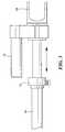
- FIG. 3is a highly schematic three-dimensional view showing how the upper robot arm includes a telescoping section
- FIG. 4is another schematic three-dimensional view of the robot arm assembly shown in FIG. 2 ;
- FIG. 5is a schematic three-dimensional rearward view of the robot arm assembly base unit in accordance with one example of the subject invention.
- FIG. 6is a schematic three-dimensional cut-away view showing the primary components associated with the base unit shown in FIG. 5 ;
- FIG. 7is a schematic three-dimensional cut-away view showing several of the primary components associated with the lower robot arm of the robot arm assembly shown in FIG. 2 ;
- FIG. 8is a schematic three-dimensional end view showing the rotatable wrist associated with the upper robot arm of the robot arm assembly shown in FIG. 2 ;
- FIG. 9is a schematic three-dimensional cut-away view showing several of the primary components associated with the rotating wrist shown in FIG. 8 .
- FIG. 1shows robot 10 driven by tracks 12 a and 12 b in accordance with one particular example of a robot in accordance with the subject invention.
- Robot 10includes deployable mast 14 , camera 16 , light 18 , antennas 20 a and 20 b , and arm assembly 22 .
- Arm assembly 22includes lower arm 24 and upper arm 26 .
- Lower arm 24is able to pitch up and down but it does not turn.
- Upper arm 26pitches with respect to lower arm 24 and is drive by chain drive 28 extending along lower arm 24 .
- Microphone 30is on upper arm as is gripper 32 which rotates via wrist 34 .
- Camera 36is typically aimed at gripper 32 .
- Operator control unit 40is used to wirelessly control robot 10 as is known in the art. The various images captured by the cameras of the robot may be displayed on view screen 41 .
- the present robot arm base unitlocated between front track wheels 50 a and 50 b ) which includes the motors and gears for pitching robot arms 24 and 26 is 15.4 inches long, 5.3 inches high, and 3.0 inches deep (thickness).
- base unit 60is dimensioned the same as the prior base unit but includes shoulder assembly 62 rotatably disposed thereon to turn lower arm 64 about axis Z.
- Robot arm 64also pitches up and down as shown by arrow 66 .
- Upper robot arm 66also pitches up and down relative to lower robot arm 64 and is driven by a motor/gear train combination inside lower arm 64 .
- Upper arm 66terminates in rotating wrist 68 driven by motor 70 . And, by pulling pin 72 in collar 74 , upper arm 66 telescopes outward as shown in FIG. 3 .
- Lower robot arm 64is pivotably attached to shoulder 62 via yoke ears 80 a and 80 b .
- Upper robot arm 66is pivotably attached to lower robot arm 64 via yoke ears 82 a and 82 b (see FIG. 4 ).
- FIG. 4also shows brake releases 90 a , 90 b , and 90 c .
- Brake release 90 ballows shoulder 62 to be manually rotated.
- Brake release 90 aallows arm 64 to be manually pitched up (or down), and brake release 90 c allows robot arm 66 to be manually folded down (or up). In this way, when the various motors of the robot arms are deenergized, the robot arms are locked in place to save battery power but the brakes can be released to fold the arms for easier transport of the robot.
- FIG. 5shows motor 100 which causes arm 64 to pitch up and down and motor 102 which causes shoulder 62 to rotate.
- Motor 100turns shaft 110 connected to shaft 112 via two stage planetary gear reducer 114 .
- Shaft 112drives gear 116 which drives gears 140 and 142 which drives gear 144 on shaft 146 extending through and rotatable with respect to shaft 118 head 120 .
- Shaft 146is attached to yoke arm 80 b and to yoke arm 80 a via gear 144 and thus motor 100 rotates yoke arms 80 a/b to pitch the lower robot arm up and down.
- Motor 102drives shaft 130 which in turn drives shaft 132 via two stage planetary gear reducer 134 .
- Bevel gear 136 on shaft 132drives gear 117 fixed to main shaft 118 which extends to head 120 fixed inside shoulder 62 .
- energizing motor 102rotates head 120 and thus shoulder 62 .
- gear 144When shaft 118 rotates, gear 144 walks around on gear 142 causing yoke arms 80 a and 80 b to pitch. So, if only rotation of shoulder 62 is desired, motor 102 is operated to run in the opposite direction of motor 100 to prevent pitching of the lower robot arm 64 . The same is not true for pitching: if only pitching of the robot arm 64 is desired, motor 102 is held stationary while motor 102 is operated to pitch arm 64 .
- Brake 160operates to automatically lock shaft 110 when motor 100 is deenergized. In this way, shaft 146 is locked in place and the lower robot arm does not pitch up or down.
- brake 162operates to automatically lock shaft 130 when motor 102 is deenergized. In this way, shoulder 62 is held in place rotationally. It is sometimes desirable, however, to release brakes 160 and 162 in order to manually rotate shoulder 62 and pivot (pitch) the lower robot arm 64 downward (or upward).
- Brake release 90 bis pulled which, via cam 170 , pushes a release built into brake 162 .
- brake release 90 avia cam 172 , pushes a release built into brake 160 .
- Encoders 180 a and 180 bare used to sense the speed of shafts 110 and 130 , respectively, for motor control.
- the position of the pitch and rotational motions of the shoulderis determined via potentiometers driven by the output shafts 112 and 132 of the drive motors. Both outputs shafts 112 and 132 have spur gear pinions 181 a and 181 b respectively connected to them. Spurs gear pinions 181 a and 181 b drive mating spur gears 182 a and 182 b which are connected to the shafts of potentiometers 183 a and 183 b.
- lower robot arm 64FIG. 7 includes motor 200 controlled by motor controller 202 which drives yoke arms 82 a , 82 b , FIG. 2 to pivot upper arm 66 with respect to lower arm 64 .
- Brake 204FIG. 7 locks motor shaft 206 in place when motor 200 is deenergized to prevent movement of upper arm 66 , FIG. 2 with respect to lower arm 64 .
- Brake release 90 cFIG. 7 releases brake 204 .
- Encoder 208is used to sense speed of motor shaft 206 .
- Motor 200turns yoke arms 82 a/b via planetary gear reducer 210 and right angle gear box 212 .
- Output shaft 213 of planetary gear reducer 210drives input pinion 214 of right angle gearbox 212 .
- Input pinion 214drives output gear 215 .
- This gear pairmay have any possible ratio.
- Output gear 215drives output shaft 216 which is connected to yoke arms 82 a / 82 b .
- Output shaft 213 of planetary gear reducer 210is also attached to spur gear 217 which drives spur gear 218 .
- Spur gear 218is connected to potentiometer 219 . Potentiometer 219 gives absolute position location of output shaft 216 .
- FIGS. 8-9One example of upper robot arm 66 is shown in FIGS. 8-9 .
- Motor 70through gear box 240 rotates wrist 68 .
- FIG. 9shows outer tube 250 and inner tube 252 which telescopes inside outer tube 250 .
- Motor 70is attached to planetary gear reducer 251 which drives output shaft 252 .
- Output shaft 252drives input gear 253 which drives output gear 255 through idler gear 254 .
- Output gear 255is fixed to drive hub 256 which in turn drives wrist output 68 .
- wrist motor 70is not powered, wrist movement is held fixed by spring-set electromagnetic brake 257 .
- the absolute position of wrist output 68is transmitted via shaft 259 to potentiometer 258 which remains fixed in inner tube 252 . Electrical power and signals are transmitted through slip ring 260 to wrist mounted devices.
- the robot armwill provide 2700 in-lbs pitch torque and 1800 in-lbs rotational torque at the shoulder joint, 1800 in-lbs of pitch torque at the elbow, and 176 in-lbs of roll torque at the wrist.
- designis scalable based upon motor size, gearbox selection and gear selection.
Landscapes
- Engineering & Computer Science (AREA)
- Robotics (AREA)
- Mechanical Engineering (AREA)
- Multimedia (AREA)
- Manipulator (AREA)
Abstract
Description
This subject invention relates to mobile, remotely controlled robots.
Mobile, remotely controlled robots are becoming increasingly popular for use by the military, SWAT units, and police and fire departments. The applicants' TALON® robot, for example, includes an arm with an end effecter, several cameras, several antennas, and a deployable mast.
Presently, the lower robot arm has only one degree of freedom, i.e. it pitches up and down relative to the robot frame. The upper robot arm pivots with respect to the lower robot arm via a chain drive on the lower arm.
For certain missions, it would be desirable to turn the lower (hence the entire) robot arm. Robot arms with shoulders which allow the robot arm to turn (yaw) are known but, for robots like the TALON® robot, it can be difficult, due to size and weight constraints, to add a shoulder and the associated motors, transmissions for driving it.
Such robots are used in extremely harsh and hostile conditions and thus any component of the robot, including the robot arm assembly, must be fairly robust. Also, it may be undesirable, in some instances, to pivot the upper robot arm with respect to the lower robot arm via a chain drive.
There is also a need to be able to manually stow the arm quickly in order to place the robot in a vehicle. But, it is preferable that the arm remain in position even when its motors are not energized to save battery power.
It is therefore an object of this invention to provide a mobile, remotely controlled robot with a compact base unit including a shoulder which allows the robot arm to turn (to yaw).
It is a further object of this invention to provide such a compact base unit which can be retrofitted into existing robots.
It is a further object of this invention to provide such a base unit which provides increased torque for the robot arm both in pitch and in yaw.
It is a further object of this invention to provide a robot arm assembly which can be manually folded for transport.
The subject invention results from the realization, in part, that if a main shaft is driven to rotate the robot shoulder and if a second shaft extends through the main shaft and is driven to pitch the robot arm up and down, a compact base unit can be effected which can be retrofitted into existing robots.
The subject invention, however, in other embodiments, need not achieve all these objectives and the claims hereof should not be limited to structures or methods capable of achieving these objectives.
The subject invention, in one example, features a robot arm base unit. A shoulder assembly is rotatably disposed on the base unit and a lower robot arm pivotably attached to the shoulder assembly. An upper robot arm is pivotably attached to the lower robot arm. The preferred base unit includes a first motor which rotates a main shaft fixed to the shoulder assembly to rotate the shoulder. A second motor rotates a second shaft in the shoulder assembly extending through the main shaft to pivot the lower robot arm with respect to the shoulder.
In one example, the lower robot arm includes a third motor for pivoting the upper robot arm. Preferably, a brake is associated with each motor for locking the shoulder with respect to the base unit, for locking the lower robot arm with respect to the shoulder, and for locking the upper robot arm with respect to the lower robot arm automatically when the motors are de-energized. There is typically a brake release associated with each brake for manually rotating the shoulder assembly, pivoting the lower robot arm, and pivoting the upper robot arm.
In one example, the upper robot arm includes at least one telescoping section. The lower robot arm may be pivotably attached to the shoulder assembly via a yoke. There may be a gear reducer between the main shaft and the first motor. And, there may be a gear on the second shaft in the shoulder driven by a gear train. There is also typically a gear reducer between the second motor and the gear train.
In the preferred embodiment, the upper robot arm includes a rotatable wrist and a motor for driving the rotatable wrist.
One robot arm assembly in accordance with this invention includes a base unit, a shoulder assembly rotatably disposed on the base unit, and a lower robot arm pivotably attached to the shoulder assembly. The preferred base unit includes a first motor which rotates a main shaft fixed to the shoulder assembly to rotate the shoulder and a second shaft in the shoulder assembly to pivot the lower robot arm with respect to the shoulder.
The typical robot arm assembly may further include an upper robot arm pivotably attached to the lower robot arm. Then, the lower robot arm includes a third motor for pivoting the upper robot arm.
In one example, a robot arm assembly comprises a base unit, a shoulder assembly rotatably disposed on the base unit, a lower robot arm pivotably attached to the shoulder assembly, and an upper robot arm pivotably attached to the lower robot arm and driven by a motor in the lower robot arm. The upper robot arm includes a telescoping section and a motor driven rotatable wrist. The preferred base unit includes a first motor which rotates a main shaft fixed to the shoulder assembly to rotate the shoulder and a second shaft in the shoulder assembly extending through the main shaft to pivot the lower robot arm with respect to the shoulder. The preferred base unit also includes a gear fixed to the main shaft driven by the first motor through a gear reducer. The preferred shoulder includes a gear fixed to the second shaft driven by the second motor through a gear train and a gear reducer. A brake with a release is associated with the first motor and a brake with a release is also associated with the second motor.
Other objects, features and advantages will occur to those skilled in the art from the following description of a preferred embodiment and the accompanying drawings, in which:
Aside from the preferred embodiment or embodiments disclosed below, this invention is capable of other embodiments and of being practiced or being carried out in various ways. Thus, it is to be understood that the invention is not limited in its application to the details of construction and the arrangements of components set forth in the following description or illustrated in the drawings. If only one embodiment is described herein, the claims hereof are not to be limited to that embodiment. Moreover, the claims hereof are not to be read restrictively unless there is clear and convincing evidence manifesting a certain exclusion, restriction, or disclaimer.
As discussed in the Background section above, it would be desirable for some missions to turn robot arm22. Traditional robot arm shoulder assemblies, however, are not well-suited for integration intorobot 10. There are often too bulky, weigh too much, and/or are not sufficiently robust. The present robot arm base unit (located betweenfront track wheels robot arms
In one preferred design,base unit 60,FIG. 2 is dimensioned the same as the prior base unit but includesshoulder assembly 62 rotatably disposed thereon to turnlower arm 64 about axis Z.Robot arm 64 also pitches up and down as shown byarrow 66.Upper robot arm 66 also pitches up and down relative to lowerrobot arm 64 and is driven by a motor/gear train combination insidelower arm 64.Upper arm 66 terminates in rotatingwrist 68 driven bymotor 70. And, by pullingpin 72 incollar 74,upper arm 66 telescopes outward as shown inFIG. 3 .
Whenshaft 118 rotates,gear 144 walks around ongear 142 causingyoke arms shoulder 62 is desired,motor 102 is operated to run in the opposite direction ofmotor 100 to prevent pitching of thelower robot arm 64. The same is not true for pitching: if only pitching of therobot arm 64 is desired,motor 102 is held stationary whilemotor 102 is operated to pitcharm 64.
The position of the pitch and rotational motions of the shoulder is determined via potentiometers driven by theoutput shafts outputs shafts spur gear pinions potentiometers
In one example,lower robot arm 64,FIG. 7 includesmotor 200 controlled bymotor controller 202 which drivesyoke arms FIG. 2 to pivotupper arm 66 with respect tolower arm 64.Brake 204,FIG. 7 locks motorshaft 206 in place whenmotor 200 is deenergized to prevent movement ofupper arm 66,FIG. 2 with respect tolower arm 64.Brake release 90c,FIG. 7 releases brake204.Encoder 208 is used to sense speed ofmotor shaft 206.Motor 200 turnsyoke arms 82a/bviaplanetary gear reducer 210 and rightangle gear box 212.Output shaft 213 ofplanetary gear reducer 210 drivesinput pinion 214 ofright angle gearbox 212.Input pinion 214 drivesoutput gear 215. This gear pair may have any possible ratio.Output gear 215 drivesoutput shaft 216 which is connected toyoke arms 82a/82b.Output shaft 213 ofplanetary gear reducer 210 is also attached to spurgear 217 which drivesspur gear 218.Spur gear 218 is connected topotentiometer 219.Potentiometer 219 gives absolute position location ofoutput shaft 216.
One example ofupper robot arm 66 is shown inFIGS. 8-9 .Motor 70, throughgear box 240 rotateswrist 68.FIG. 9 showsouter tube 250 andinner tube 252 which telescopes insideouter tube 250.Motor 70 is attached toplanetary gear reducer 251 which drivesoutput shaft 252.Output shaft 252 drivesinput gear 253 which drivesoutput gear 255 throughidler gear 254.Output gear 255 is fixed to drivehub 256 which in turn driveswrist output 68. Whenwrist motor 70 is not powered, wrist movement is held fixed by spring-setelectromagnetic brake 257. The absolute position ofwrist output 68 is transmitted viashaft 259 topotentiometer 258 which remains fixed ininner tube 252. Electrical power and signals are transmitted throughslip ring 260 to wrist mounted devices.
In one example, the robot arm will provide 2700 in-lbs pitch torque and 1800 in-lbs rotational torque at the shoulder joint, 1800 in-lbs of pitch torque at the elbow, and 176 in-lbs of roll torque at the wrist. However, design is scalable based upon motor size, gearbox selection and gear selection.
Although specific features of the invention are shown in some drawings and not in others, this is for convenience only as each feature may be combined with any or all of the other features in accordance with the invention. The words “including”, “comprising”, “having”, and “with” as used herein are to be interpreted broadly and comprehensively and are not limited to any physical interconnection. Moreover, any embodiments disclosed in the subject application are not to be taken as the only possible embodiments. Other embodiments will occur to those skilled in the art and are within the following claims.
In addition, any amendment presented during the prosecution of the patent application for this patent is not a disclaimer of any claim element presented in the application as filed: those skilled in the art cannot reasonably be expected to draft a claim that would literally encompass all possible equivalents, many equivalents will be unforeseeable at the time of the amendment and are beyond a fair interpretation of what is to be surrendered (if anything), the rationale underlying the amendment may bear no more than a tangential relation to many equivalents, and/or there are many other reasons the applicant can not be expected to describe certain insubstantial substitutes for any claim element amended.
Claims (24)
1. A robot arm assembly comprising:
a base unit;
a shoulder assembly rotatably disposed on the base unit;
a lower robot arm pivotably attached to the shoulder assembly;
an upper robot arm pivotably attached to the lower robot arm;
a main shaft rotatably disposed in the base unit and connected to the shoulder assembly;
the base unit including a first motor which rotates the main shaft connected to the shoulder assembly to rotate the shoulder assembly;
a second shaft rotatably disposed in the shoulder assembly and extending transversely through and rotatable with respect to the main shaft and connected to the lower robot arm;
the base unit further including a second motor which rotates the second shaft in the shoulder assembly to pivot the lower robot arm with respect to the shoulder assembly.
2. The robot arm assembly ofclaim 1 in which the lower robot arm includes a third motor for pivoting the upper robot arm.
3. The robot arm assembly ofclaim 2 further including a brake associated with each motor for locking the shoulder with respect to the base unit, for locking the lower robot arm with respect to the shoulder, and for locking the upper robot arm with respect to the lower robot arm automatically when the motors are de-energized.
4. The robot arm assembly ofclaim 3 further including a brake release for each brake for manually rotating the shoulder assembly, pivoting the lower robot arm, and pivoting the upper robot arm.
5. The robot arm assembly ofclaim 1 in which the upper robot arm includes at least one telescoping section.
6. The robot arm assembly ofclaim 1 in which the lower robot arm is pivotably attached to the shoulder assembly via a yoke.
7. The robot arm assembly ofclaim 1 in which there is a gear fixed to the main shaft driven by the first motor.
8. The robot arm assembly ofclaim 7 including a gear reducer between the main shaft and the first motor.
9. The robot arm assembly ofclaim 1 in which there is a gear on the second shaft in the shoulder driven by a gear train.
10. The robot arm assembly ofclaim 9 in which there is a gear reducer between the second motor and the gear train.
11. The robot arm assembly ofclaim 1 in which the upper robot arm includes a rotatable wrist and a motor for driving the rotatable wrist.
12. A robot arm assembly comprising:
a base unit;
a shoulder assembly rotatably disposed on the base unit;
a lower robot arm pivotably attached to the shoulder assembly;
a main vertical shaft rotatably disposed in the base unit and connected to the shoulder assembly;
the base unit including a first motor which rotates the main vertical shaft connected to the shoulder assembly to rotate the shoulder assembly; and
a second horizontal shaft rotatably disposed in the shoulder assembly and extending transversely through and rotatable with respect to the main shaft and connected to the lower robot arm;
the base unit further including a second motor which rotates the second horizontal shaft in the shoulder assembly to pivot the lower robot arm with respect to the shoulder assembly.
13. The robot arm assembly ofclaim 12 further including an upper robot arm pivotably attached to the lower robot arm.
14. The robot arm assembly ofclaim 13 in which the lower robot arm includes a third motor for pivoting the upper robot arm.
15. The robot arm assembly ofclaim 14 further including a brake associated with each motor for locking the shoulder with respect to the base unit, for locking the lower robot arm with respect to the shoulder, and for locking the upper robot arm with respect to the lower robot arm automatically when the motors are de-energized.
16. The robot arm assembly ofclaim 15 further including a brake release for each brake for manually rotating the shoulder assembly, pivoting the lower robot arm, and pivoting the upper robot arm.
17. The robot arm assembly ofclaim 13 in which the upper robot arm includes at least one telescoping section.
18. The robot arm assembly ofclaim 13 in which the upper robot arm includes a rotatable wrist and a motor for driving the rotatable wrist.
19. The robot arm assembly ofclaim 12 in which the lower robot arm is pivotably attached to the shoulder assembly via a yoke.
20. The robot arm assembly ofclaim 12 in which there is a gear fixed to the main shaft driven by the first motor.
21. The robot arm assembly ofclaim 20 including a gear reducer between the main shaft and the first motor.
22. The robot arm assembly ofclaim 12 in which there is a gear on the second shaft driven by a gear train.
23. The robot arm assembly ofclaim 22 in which there is a gear reducer between the second motor and the gear train.
24. A robot arm assembly comprising:
a base unit;
a shoulder assembly rotatably disposed on the base unit;
a lower robot arm pivotably attached to the shoulder assembly;
an upper robot arm pivotably attached to the lower robot arm and driven by a motor in the lower robot arm, the upper robot arm including a telescoping section and a motor driven rotatable wrist;
a main shaft rotatably disposed in the base unit and connected to the shoulder assembly;
a second shaft rotatably disposed in the shoulder assembly and extending transversely through and rotatable with respect to the main shaft and connected to the lower robot arm;
the base unit including:
a first motor which rotates the main shaft connected to the shoulder assembly to rotate the shoulder,
a second motor which rotates the second shaft in the shoulder assembly to pivot the lower robot arm with respect to the shoulder assembly,
a gear fixed to the main shaft driven by the first motor through a gear reducer,
a brake with a release associated with the first motor, and
a brake with a release associated with the second motor; and
the shoulder assembly including a gear fixed to the second shaft driven by the second motor through a gear train and a gear reducer.
Priority Applications (2)
| Application Number | Priority Date | Filing Date | Title |
|---|---|---|---|
| US11/901,200US8176808B2 (en) | 2007-09-13 | 2007-09-13 | Robot arm assembly |
| PCT/US2008/008701WO2009035490A1 (en) | 2007-09-13 | 2008-07-17 | Robot arm assembly |
Applications Claiming Priority (1)
| Application Number | Priority Date | Filing Date | Title |
|---|---|---|---|
| US11/901,200US8176808B2 (en) | 2007-09-13 | 2007-09-13 | Robot arm assembly |
Publications (2)
| Publication Number | Publication Date |
|---|---|
| US20090071281A1 US20090071281A1 (en) | 2009-03-19 |
| US8176808B2true US8176808B2 (en) | 2012-05-15 |
Family
ID=40452302
Family Applications (1)
| Application Number | Title | Priority Date | Filing Date |
|---|---|---|---|
| US11/901,200Expired - Fee RelatedUS8176808B2 (en) | 2007-09-13 | 2007-09-13 | Robot arm assembly |
Country Status (2)
| Country | Link |
|---|---|
| US (1) | US8176808B2 (en) |
| WO (1) | WO2009035490A1 (en) |
Cited By (12)
| Publication number | Priority date | Publication date | Assignee | Title |
|---|---|---|---|---|
| US20110265597A1 (en)* | 2010-04-29 | 2011-11-03 | Hon Hai Precision Industry Co., Ltd. | Robot arm assembly |
| US20130006444A1 (en)* | 2011-07-01 | 2013-01-03 | Cardinal Gibbons High School | Folding Forklift |
| US20130139636A1 (en)* | 2010-09-28 | 2013-06-06 | Harmonic Drive Systems Inc. | Rotary actuator equipped with sensing mechanism, and joint unit |
| US8532819B2 (en)* | 2009-05-19 | 2013-09-10 | Canon Kabushiki Kaisha | Manipulator with camera |
| US20150323501A1 (en)* | 2012-07-12 | 2015-11-12 | The Boeing Company | Extended reach inspection apparatus |
| USD752114S1 (en)* | 2012-06-04 | 2016-03-22 | Caterpillar Work Tools B.V. | Multi-processor and modular wear protection system |
| WO2018057448A1 (en) | 2016-09-20 | 2018-03-29 | Foster-Miller, Inc. | Remotely controlled packable robot |
| US10471589B2 (en) | 2016-09-20 | 2019-11-12 | Foster-Miller, Inc. | Remotely controlled packable robot |
| US20200231082A1 (en)* | 2019-01-21 | 2020-07-23 | Kevin Arnold Morran | Remote controlled lighting apparatus |
| US10889340B2 (en) | 2017-07-07 | 2021-01-12 | Foster-Miller, Inc. | Remotely controlled packable robot with folding tracks |
| US11254015B2 (en) | 2019-09-24 | 2022-02-22 | Thermo Crs Ltd. | Multi-axis gripper for lab automation robot |
| US11331818B2 (en) | 2018-10-11 | 2022-05-17 | Foster-Miller, Inc. | Remotely controlled packable robot |
Families Citing this family (32)
| Publication number | Priority date | Publication date | Assignee | Title |
|---|---|---|---|---|
| US8176808B2 (en) | 2007-09-13 | 2012-05-15 | Foster-Miller, Inc. | Robot arm assembly |
| US8201649B2 (en)* | 2007-12-14 | 2012-06-19 | Foster-Miller, Inc. | Modular mobile robot |
| USD609259S1 (en)* | 2008-09-01 | 2010-02-02 | Prosurgics Limited | Accessory for a robot arm |
| US8414043B2 (en)* | 2008-10-21 | 2013-04-09 | Foster-Miller, Inc. | End effector for mobile remotely controlled robot |
| US20100101356A1 (en)* | 2008-10-24 | 2010-04-29 | Albin Scott R | Remotely controlled mobile robot in-line robot arm and end effector mechanism |
| US8322249B2 (en)* | 2008-12-18 | 2012-12-04 | Foster-Miller, Inc. | Robot arm assembly |
| EP2375104B1 (en)* | 2008-12-19 | 2013-04-24 | Kawabuchi Mechanical Engineering Laboratory, Inc. | Linearly moving extendable mechanism and robot arm equipped with linearly moving extendable mechanism |
| US8141924B2 (en)* | 2008-12-29 | 2012-03-27 | Foster-Miller, Inc. | Gripper system |
| WO2010101203A1 (en)* | 2009-03-06 | 2010-09-10 | 株式会社安川電機 | Articulation unit for robot and robot |
| JP2011082952A (en)* | 2009-09-09 | 2011-04-21 | Sony Corp | Communication system, communication apparatus, communication method, and computer program |
| IT1400536B1 (en)* | 2010-05-26 | 2013-06-11 | Oto Melara Spa | ROBOT ARM FOR A VEHICLE. |
| US9248576B2 (en)* | 2010-05-31 | 2016-02-02 | National Institute Of Advanced Industrial Science And Technology | Direct acting extensible and retractable arm mechanism, and robot arm provided with direct acting extensible and retractable arm mechanism |
| US8738198B2 (en) | 2011-05-26 | 2014-05-27 | Foster-Miller, Inc. | Robot surveillance system and method |
| CN102513987B (en)* | 2011-12-26 | 2014-04-09 | 浙江金刚汽车有限公司 | Intelligent fire-fighting rescue robot |
| ITPR20120005A1 (en)* | 2012-02-14 | 2013-08-15 | Andrea Medici | MULTIFUNCTIONAL MULTIFUNCTIONAL MEANS |
| US10233033B2 (en) | 2013-11-27 | 2019-03-19 | Diebotics Ip, Llc | Multiple axis work-piece tranfser apparatus |
| CN103737573B (en)* | 2014-01-08 | 2016-05-04 | 东南大学 | A kind of search and rescue robot |
| WO2015132677A2 (en)* | 2014-02-24 | 2015-09-11 | Metalsa S.A. De C.V. | Process of positioning automotive components |
| WO2015125020A2 (en) | 2014-02-24 | 2015-08-27 | Metalsa S.A. De C.V. | Method and tools for welding a vehicle component |
| CN103802132B (en)* | 2014-03-04 | 2016-07-06 | 中国人民解放军军事医学科学院卫生装备研究所 | There is target and follow the foldable lightweight mechanical arm of function for monitoring |
| JP6482136B2 (en)* | 2014-03-14 | 2019-03-13 | ライフロボティクス株式会社 | Telescopic arm mechanism |
| FR3018894B1 (en)* | 2014-03-19 | 2016-12-30 | Commissariat Energie Atomique | PORTABLE CAMERA DEVICE TO BE ATTACHED TO A TELEMANIPULATOR CLIP |
| US10196158B2 (en) | 2016-04-29 | 2019-02-05 | The Boeing Company | Portable programmable machine |
| CN108438085B (en)* | 2016-05-04 | 2020-09-22 | 泰州市扬帆车件有限公司 | Fire fighting equipment |
| US20220381374A1 (en)* | 2020-01-20 | 2022-12-01 | Techreo LCC | Tubular structures |
| CN110303513A (en)* | 2019-03-27 | 2019-10-08 | 陈志君 | Self-service case notes robot and its system of being informed of a case |
| CN110370318B (en)* | 2019-07-30 | 2020-11-06 | 南京昱晟机器人科技有限公司 | Industrial robot with self fault detection function |
| CN110464481B (en)* | 2019-08-19 | 2022-09-20 | 王衍廷 | Brain surgery stereotaxic apparatus with double locking function and locking method |
| CN112536806B (en)* | 2020-11-30 | 2022-03-29 | 广东电网有限责任公司电力科学研究院 | Robot for inspecting cable trench and control system thereof |
| US12042934B1 (en)* | 2021-11-15 | 2024-07-23 | Tiger Tool International Incorporated | Support systems and methods for robot arm assembly |
| USD1089348S1 (en)* | 2022-11-11 | 2025-08-19 | Dimitrije Stojanovski | Robotic arm assembly |
| CN115648283A (en)* | 2022-12-27 | 2023-01-31 | 沈阳新松机器人自动化股份有限公司 | Long-arm unfolding high-flexibility disassembling robot |
Citations (130)
| Publication number | Priority date | Publication date | Assignee | Title |
|---|---|---|---|---|
| US429903A (en) | 1890-06-10 | Post-hole digger | ||
| US816236A (en) | 1905-09-21 | 1906-03-27 | Rudolph D Kline | Transplanting device. |
| US832541A (en) | 1905-11-11 | 1906-10-02 | William A Dodge | Combination tack-puller and stove-lid lifter. |
| US1350124A (en) | 1920-01-22 | 1920-08-17 | Blaw Knox Co | Excavating-bucket |
| US1479310A (en) | 1922-07-15 | 1924-01-01 | Oran D Monroe | Posthole digger |
| US2132795A (en) | 1938-05-24 | 1938-10-11 | Minier William | Culvert cleaner and post hole digger |
| US2221192A (en) | 1940-02-10 | 1940-11-12 | Claus A Juhl | Nail and separator removing spade |
| US2594763A (en) | 1948-04-13 | 1952-04-29 | Ernest T Freyer | Clam-shell bucket |
| US2613100A (en) | 1951-12-06 | 1952-10-07 | Jr Walter Lee Casey | Article grasping and handling device |
| US2617203A (en) | 1948-10-13 | 1952-11-11 | Orval D Murray | Drier |
| US2617211A (en) | 1947-07-21 | 1952-11-11 | William A Olson | Clamshell bucket |
| US2665434A (en) | 1950-08-28 | 1954-01-12 | George L Saunders | Means for mounting blades on hand implements |
| US2710765A (en) | 1950-03-09 | 1955-06-14 | Arens Charles Anthony | Post hole digger |
| US2891813A (en) | 1956-07-12 | 1959-06-23 | Inaki Toyojiro | Material handling tool |
| US2926865A (en) | 1955-09-08 | 1960-03-01 | Robert B Humphreys | Electric razor cord take-up reel |
| US3042440A (en) | 1959-03-17 | 1962-07-03 | Sr Alfred Henry Weil | Post hole digger |
| US3108498A (en)* | 1958-09-19 | 1963-10-29 | Gen Mills Inc | Remote control manipulator drives |
| US3202449A (en) | 1963-04-29 | 1965-08-24 | Jerome H Lemelson | Article manipulation device |
| US3247979A (en)* | 1962-12-14 | 1966-04-26 | Programmed & Remote System Cor | Manipulator control system |
| US3370213A (en) | 1965-04-26 | 1968-02-20 | Programmed & Remote Syst Corp | Force control system for manipulator component |
| USRE26904E (en) | 1963-01-14 | 1970-06-09 | Jerome H Lemelson | Article manipulation apparatus |
| US3558177A (en) | 1968-10-10 | 1971-01-26 | William C Snead | Plant digging machine |
| US3645578A (en) | 1970-01-29 | 1972-02-29 | Charles L Renfroe | Easy hole digger |
| US3765347A (en) | 1972-02-07 | 1973-10-16 | Kopparfors Ab | Planting device |
| US3866966A (en) | 1973-05-14 | 1975-02-18 | Ii Frank R Skinner | Multiple prehension manipulator |
| US3914884A (en) | 1973-05-14 | 1975-10-28 | Poclain Sa | Double bladed axially articulated excavator scoop |
| US3920137A (en) | 1974-04-08 | 1975-11-18 | Willard E Mccain | Excavating machine with clamshell bucket |
| US3952880A (en) | 1973-10-15 | 1976-04-27 | Stanford Research Institute | Force and torque sensing method and means for manipulators and the like |
| US4000784A (en) | 1975-04-24 | 1977-01-04 | The Manitowoc Company, Inc. | Demountable self-propelled crane transport assembly |
| US4062455A (en) | 1976-11-22 | 1977-12-13 | Flatau Carl R | Remote manipulator |
| US4097084A (en) | 1977-03-18 | 1978-06-27 | Russkraft, Inc. | Lifting grab for cylindrical objects |
| US4114464A (en) | 1976-02-25 | 1978-09-19 | Messerschmitt-Bolkow-Blohm Gesellschaft Mit Beschrankter Haftung | Artificial hand and drive apparatus for such hand |
| US4281866A (en) | 1979-08-27 | 1981-08-04 | Atcheson James E | Weed puller and ejector |
| US4367893A (en) | 1980-01-17 | 1983-01-11 | Asea Aktiebolag | Gripping device |
| US4370091A (en) | 1979-07-18 | 1983-01-25 | Ateliers Et Chantiers De Bretagne | Remote manipulator arm |
| US4456293A (en) | 1982-08-24 | 1984-06-26 | International Business Machines Corporation | Article gripping apparatus |
| US4478451A (en) | 1981-06-16 | 1984-10-23 | Dango & Dienenthal Maschinenbau Gmbh | Mechanically operated tongs for gripping round objects |
| US4489969A (en) | 1982-09-30 | 1984-12-25 | Clayton Merry | Clam digging tool |
| US4494441A (en) | 1983-08-08 | 1985-01-22 | The United States Of America As Represented By The Secretary Of The Army | Ammunition feed trunnion support |
| US4501522A (en)* | 1981-10-26 | 1985-02-26 | United Kingdom Atomic Energy Authority | Manipulator |
| US4512524A (en) | 1983-09-16 | 1985-04-23 | Takachiho Kogyo Yuugen Kaisha | Crusher for concrete structures |
| US4600355A (en) | 1984-08-29 | 1986-07-15 | Cybot, Inc. | Modular robotics system with basic interchangeable parts |
| US4600357A (en) | 1984-02-21 | 1986-07-15 | Heath Company | Gripper force sensor/controller for robotic arm |
| US4621562A (en) | 1983-05-31 | 1986-11-11 | Monitor Engineers Limited | Remote control robot vehicle |
| USD287218S (en) | 1984-08-08 | 1986-12-16 | Usm Corporation | Head unit for a post hole digger |
| US4645409A (en) | 1982-02-05 | 1987-02-24 | American Cimflex Corporation | Outer arm assembly for industrial robot |
| US4648464A (en) | 1984-07-05 | 1987-03-10 | Black & Decker Inc. | Cultivating tool |
| US4678220A (en) | 1986-02-14 | 1987-07-07 | Gabriel Edwin Z | Shovel-like coupling devices with automatic material handling features |
| US4697838A (en) | 1985-06-10 | 1987-10-06 | Hartman John F | Robot gripping jaw operator |
| US4699414A (en) | 1986-04-21 | 1987-10-13 | The United States Of America As Represented By The Secretary Of The Air Force | Multi use gripper for industrial robot |
| US4709265A (en) | 1985-10-15 | 1987-11-24 | Advanced Resource Development Corporation | Remote control mobile surveillance system |
| US4738576A (en)* | 1983-04-06 | 1988-04-19 | Mantec Gesellschaft fur Automatisierungs-und Handhabungssysteme mbH | Robot joint |
| US4766775A (en)* | 1986-05-02 | 1988-08-30 | Hodge Steven W | Modular robot manipulator |
| US4773298A (en) | 1985-12-04 | 1988-09-27 | Heinz Tischer | Method for neutralizing surface-laid or camouflaged land mines and mobile unit for performing the method |
| US4778211A (en) | 1986-07-21 | 1988-10-18 | Gabriel Edwin Z | Shovel-like, digging, scooping and transporting apparatus |
| US4784422A (en) | 1985-03-06 | 1988-11-15 | Universal Machine Intelligence Ltd. | Gripper and wrist joint for a robotic arm |
| US4810019A (en) | 1987-02-05 | 1989-03-07 | Bruecher Eberhard | Mechanically operated collet chuck for gripping round objects |
| US4822238A (en) | 1986-06-19 | 1989-04-18 | Westinghouse Electric Corp. | Robotic arm |
| US4822233A (en) | 1986-09-15 | 1989-04-18 | A. Raymond | Apparatus for removing sprue slugs from an injection molding machine |
| US4865400A (en) | 1984-09-21 | 1989-09-12 | Caron Compactor Co. | Demolition and compaction track shoe and assembly for crawler vehicle |
| US4932831A (en) | 1988-09-26 | 1990-06-12 | Remotec, Inc. | All terrain mobile robot |
| US4941416A (en) | 1988-12-01 | 1990-07-17 | Faulring Frank W | Actuating mechanism for a ground-engaging tool |
| US4993914A (en) | 1989-05-30 | 1991-02-19 | Riddle James W | Fallen tree removal implement |
| US5024397A (en) | 1990-02-14 | 1991-06-18 | International Paper | Clamshell attachment for log grapple |
| US5033785A (en) | 1990-04-20 | 1991-07-23 | Woolley Jr William J | Clamp mechanism |
| US5060378A (en) | 1989-12-15 | 1991-10-29 | Labounty Manufacturing, Inc. | Demolition tool for a hydraulic excavator |
| US5063628A (en) | 1990-03-05 | 1991-11-12 | Campbell Larry E | Survival device |
| US5081941A (en) | 1990-03-27 | 1992-01-21 | Weeks Paul R | Apparatus for excavating and transplanting trees and the like |
| US5098024A (en) | 1990-07-27 | 1992-03-24 | Northrop Corporation | Spray end effector |
| US5195388A (en) | 1990-10-04 | 1993-03-23 | Comau Spa | Articulated robot |
| US5222409A (en) | 1991-09-25 | 1993-06-29 | Dalakian Sergei V | Industrial robot arms |
| US5360071A (en) | 1993-08-05 | 1994-11-01 | Bergendorf Frank H | Gardening tool having diverging prongs and straight prongs |
| US5385311A (en) | 1993-01-26 | 1995-01-31 | Ohyodo Komatsu Co., Ltd. | Breaking equipment |
| US5427424A (en) | 1994-06-30 | 1995-06-27 | Robinson; John A. | Single handle post hole digger |
| US5435405A (en) | 1993-05-14 | 1995-07-25 | Carnegie Mellon University | Reconfigurable mobile vehicle with magnetic tracks |
| US5440916A (en) | 1993-11-15 | 1995-08-15 | The United States Of America As Represented By The Administrator Of The National Aeronatics And Space Administration | Emergency response mobile robot for operations in combustible atmospheres |
| US5443354A (en) | 1992-07-20 | 1995-08-22 | The United States Of America As Represented By The Administrator Of The National Aeronautics And Space Administration | Hazardous materials emergency response mobile robot |
| US5474242A (en) | 1994-10-11 | 1995-12-12 | The Stanley Works | Demolition tools with jaws having replaceable working surfaces |
| US5485691A (en) | 1994-08-24 | 1996-01-23 | Easymove, Inc. | Apparatus for excavating and transplanting trees and the like and method of use |
| US5570992A (en) | 1954-07-28 | 1996-11-05 | Lemelson; Jerome H. | Free-traveling manipulator with optical feedback control and methods |
| US5600904A (en) | 1995-04-26 | 1997-02-11 | Bowling; John M. | Impact driven tree transplanting apparatus |
| US5672044A (en) | 1974-01-24 | 1997-09-30 | Lemelson; Jerome H. | Free-traveling manipulator with powered tools |
| US5769341A (en) | 1996-10-15 | 1998-06-23 | Ohyodo Diesel Co., Ltd. | Stabilized crushing device |
| US5842427A (en) | 1996-04-08 | 1998-12-01 | Hunter; James Edward | Apparatus for mounting on a tractor or other vehicle and providing opposed movement to digging or lifting implements |
| US5872892A (en) | 1997-02-03 | 1999-02-16 | Motoman, Inc. | Process and apparatus for imparting linear motion to tooling attached to the end of a manipulator device having two different length arms |
| US5921302A (en) | 1996-07-18 | 1999-07-13 | Petersen; John M. | Method and apparatus for tree stump clearing |
| US6113343A (en) | 1996-12-16 | 2000-09-05 | Goldenberg; Andrew | Explosives disposal robot |
| US6217094B1 (en) | 1999-05-24 | 2001-04-17 | Japan Servo Co., Ltd. | Object holding device |
| US6236906B1 (en) | 1998-03-26 | 2001-05-22 | Carl-Zeiss-Stiftung | Process and apparatus for hand-controlled guiding of an instrument in a predetermined movement region |
| US6283220B1 (en) | 1998-12-10 | 2001-09-04 | J.C. Bamford Excavators Limited | Remote control vehicle |
| US6338512B1 (en) | 2000-01-31 | 2002-01-15 | Jonathan Paul Ruppert | Clamp action shovel for single hand operation |
| US6341933B1 (en) | 1999-06-04 | 2002-01-29 | Macdonald Detwiler Space & Advanced Robotics Limited | Hinged scoop end-effector |
| US6341568B1 (en) | 1999-06-22 | 2002-01-29 | Daniel A. Culley | Expandable stinger planter |
| US6377872B1 (en) | 1999-07-02 | 2002-04-23 | Bae Systems Information And Electronic Systems Integration Inc | Apparatus and method for microwave imaging and excavation of objects |
| US6431296B1 (en) | 1998-03-27 | 2002-08-13 | Irobot Corporation | Robotic platform |
| US6491127B1 (en) | 1998-08-14 | 2002-12-10 | 3Com Corporation | Powered caster wheel module for use on omnidirectional drive systems |
| US6508496B1 (en) | 2002-04-11 | 2003-01-21 | Tsung-Chi Huang | Manually-operated device for picking up objects |
| US6523284B1 (en) | 2000-02-14 | 2003-02-25 | Scot J. Clugston | Multi-purpose material handling apparatus |
| US6526678B2 (en) | 2001-03-07 | 2003-03-04 | John Albert Waddington, Jr. | Demo-dozer |
| US6615753B1 (en) | 1999-06-22 | 2003-09-09 | Northwest Revegetation | Expandable stinger planter |
| US20040006824A1 (en) | 2002-07-09 | 2004-01-15 | Chun-Hao Huang | Multi-function fire fighting tool |
| US20040030451A1 (en) | 2002-04-22 | 2004-02-12 | Neal Solomon | Methods and apparatus for decision making of system of mobile robotic vehicles |
| US20040030448A1 (en) | 2002-04-22 | 2004-02-12 | Neal Solomon | System, methods and apparatus for managing external computation and sensor resources applied to mobile robotic network |
| US20040030570A1 (en) | 2002-04-22 | 2004-02-12 | Neal Solomon | System, methods and apparatus for leader-follower model of mobile robotic system aggregation |
| US6702050B1 (en) | 2002-09-23 | 2004-03-09 | The United States Of America As Represented By The Secretary Of The Army | Robotic vehicle construction |
| US20040068416A1 (en) | 2002-04-22 | 2004-04-08 | Neal Solomon | System, method and apparatus for implementing a mobile sensor network |
| US6722296B2 (en) | 2002-08-22 | 2004-04-20 | Clyde L. Reilly | Tree spade system |
| US6766973B2 (en) | 1999-12-30 | 2004-07-27 | Franz Muri | Concrete crushing grappler |
| US6904976B1 (en) | 2003-11-24 | 2005-06-14 | Lawrence J. Zach | Powered soil tillage device |
| US20050204850A1 (en) | 2004-03-16 | 2005-09-22 | Fanuc Ltd. | Industrial robot |
| US6999849B2 (en) | 2002-01-24 | 2006-02-14 | John Clinton Bridges | Folding robotic system |
| US20060156852A1 (en)* | 2003-01-21 | 2006-07-20 | Kazuhiro Haniya | Speed reducer for industrial robot |
| US20060192515A1 (en)* | 2003-04-02 | 2006-08-31 | Kabushiki Kaisha Yaskawa Denki | Indurstrial robot controlling device |
| US7104576B1 (en) | 2005-01-27 | 2006-09-12 | Alan Dorr | Weeding shovel with footstep |
| US20060283054A1 (en) | 2005-06-21 | 2006-12-21 | Crow Stephen I Sr | Hole digging device for construction equipment |
| US20060289178A1 (en) | 2005-05-12 | 2006-12-28 | Charles Basek | Weed puller |
| US20070097382A1 (en) | 2005-10-21 | 2007-05-03 | Romer | System for identifying the position of three-dimensional machine for measuring or machining in a fixed frame of reference |
| US20070107917A1 (en) | 2005-11-14 | 2007-05-17 | Doherty Brian J | Multifunctional robot tool |
| WO2007088206A2 (en) | 2006-02-03 | 2007-08-09 | The European Atomic Energy Community (Euratom), Represented By The European Commission | Medical robotic system with manipulator arm of the cylindrical coordinate type |
| US20080073922A1 (en) | 2006-09-27 | 2008-03-27 | Oceaneering International, Inc. | Double Sided Rack Manipulator Jaw Actuator System |
| US20080083344A1 (en) | 2005-11-14 | 2008-04-10 | Deguire Daniel R | Safe and arm system for a robot |
| US20080296920A1 (en) | 2005-10-13 | 2008-12-04 | Tino Kipping | Handling System for Components Having Similar Shapes, Particularly Body Componets for Motor Vehicles |
| US20090071281A1 (en) | 2007-09-13 | 2009-03-19 | Fisk Allan T | Robot arm assembly |
| US20090107917A1 (en) | 2007-10-25 | 2009-04-30 | David Capehart | Water water purification system and method |
| US20090129003A1 (en) | 2007-09-19 | 2009-05-21 | Kurt Bruck | Operator control unit |
| US20090164045A1 (en) | 2007-12-19 | 2009-06-25 | Deguire Daniel R | Weapon robot with situational awareness |
| US20100095799A1 (en) | 2008-10-21 | 2010-04-22 | Albin Scott R | End effector for mobile remotely controlled robot |
| US20100101356A1 (en) | 2008-10-24 | 2010-04-29 | Albin Scott R | Remotely controlled mobile robot in-line robot arm and end effector mechanism |
| US20100158656A1 (en) | 2008-12-18 | 2010-06-24 | Seavey Nathaniel J M | Robot arm assembly |
| US20100164243A1 (en) | 2008-12-29 | 2010-07-01 | Albin Scott R | Gripper system |
Family Cites Families (2)
| Publication number | Priority date | Publication date | Assignee | Title |
|---|---|---|---|---|
| US4833233A (en)* | 1987-08-20 | 1989-05-23 | The United States Of America As Represented By The Administrator Of The National Aeronautics And Space Administration | Human serum albumin crystals and method of preparation |
| JPH10243982A (en)* | 1997-03-05 | 1998-09-14 | Family Kk | Chair type massage machine and operation control therefor |
- 2007
- 2007-09-13USUS11/901,200patent/US8176808B2/ennot_activeExpired - Fee Related
- 2008
- 2008-07-17WOPCT/US2008/008701patent/WO2009035490A1/enactiveApplication Filing
Patent Citations (133)
| Publication number | Priority date | Publication date | Assignee | Title |
|---|---|---|---|---|
| US429903A (en) | 1890-06-10 | Post-hole digger | ||
| US816236A (en) | 1905-09-21 | 1906-03-27 | Rudolph D Kline | Transplanting device. |
| US832541A (en) | 1905-11-11 | 1906-10-02 | William A Dodge | Combination tack-puller and stove-lid lifter. |
| US1350124A (en) | 1920-01-22 | 1920-08-17 | Blaw Knox Co | Excavating-bucket |
| US1479310A (en) | 1922-07-15 | 1924-01-01 | Oran D Monroe | Posthole digger |
| US2132795A (en) | 1938-05-24 | 1938-10-11 | Minier William | Culvert cleaner and post hole digger |
| US2221192A (en) | 1940-02-10 | 1940-11-12 | Claus A Juhl | Nail and separator removing spade |
| US2617211A (en) | 1947-07-21 | 1952-11-11 | William A Olson | Clamshell bucket |
| US2594763A (en) | 1948-04-13 | 1952-04-29 | Ernest T Freyer | Clam-shell bucket |
| US2617203A (en) | 1948-10-13 | 1952-11-11 | Orval D Murray | Drier |
| US2710765A (en) | 1950-03-09 | 1955-06-14 | Arens Charles Anthony | Post hole digger |
| US2665434A (en) | 1950-08-28 | 1954-01-12 | George L Saunders | Means for mounting blades on hand implements |
| US2613100A (en) | 1951-12-06 | 1952-10-07 | Jr Walter Lee Casey | Article grasping and handling device |
| US5570992A (en) | 1954-07-28 | 1996-11-05 | Lemelson; Jerome H. | Free-traveling manipulator with optical feedback control and methods |
| US2926865A (en) | 1955-09-08 | 1960-03-01 | Robert B Humphreys | Electric razor cord take-up reel |
| US2891813A (en) | 1956-07-12 | 1959-06-23 | Inaki Toyojiro | Material handling tool |
| US3108498A (en)* | 1958-09-19 | 1963-10-29 | Gen Mills Inc | Remote control manipulator drives |
| US3042440A (en) | 1959-03-17 | 1962-07-03 | Sr Alfred Henry Weil | Post hole digger |
| US3247979A (en)* | 1962-12-14 | 1966-04-26 | Programmed & Remote System Cor | Manipulator control system |
| USRE26904E (en) | 1963-01-14 | 1970-06-09 | Jerome H Lemelson | Article manipulation apparatus |
| US3202449A (en) | 1963-04-29 | 1965-08-24 | Jerome H Lemelson | Article manipulation device |
| US3370213A (en) | 1965-04-26 | 1968-02-20 | Programmed & Remote Syst Corp | Force control system for manipulator component |
| US3558177A (en) | 1968-10-10 | 1971-01-26 | William C Snead | Plant digging machine |
| US3645578A (en) | 1970-01-29 | 1972-02-29 | Charles L Renfroe | Easy hole digger |
| US3765347A (en) | 1972-02-07 | 1973-10-16 | Kopparfors Ab | Planting device |
| US3914884A (en) | 1973-05-14 | 1975-10-28 | Poclain Sa | Double bladed axially articulated excavator scoop |
| US3866966A (en) | 1973-05-14 | 1975-02-18 | Ii Frank R Skinner | Multiple prehension manipulator |
| US3952880A (en) | 1973-10-15 | 1976-04-27 | Stanford Research Institute | Force and torque sensing method and means for manipulators and the like |
| US5672044A (en) | 1974-01-24 | 1997-09-30 | Lemelson; Jerome H. | Free-traveling manipulator with powered tools |
| US3920137A (en) | 1974-04-08 | 1975-11-18 | Willard E Mccain | Excavating machine with clamshell bucket |
| US4000784A (en) | 1975-04-24 | 1977-01-04 | The Manitowoc Company, Inc. | Demountable self-propelled crane transport assembly |
| US4114464A (en) | 1976-02-25 | 1978-09-19 | Messerschmitt-Bolkow-Blohm Gesellschaft Mit Beschrankter Haftung | Artificial hand and drive apparatus for such hand |
| US4062455A (en) | 1976-11-22 | 1977-12-13 | Flatau Carl R | Remote manipulator |
| US4097084A (en) | 1977-03-18 | 1978-06-27 | Russkraft, Inc. | Lifting grab for cylindrical objects |
| US4370091A (en) | 1979-07-18 | 1983-01-25 | Ateliers Et Chantiers De Bretagne | Remote manipulator arm |
| US4281866A (en) | 1979-08-27 | 1981-08-04 | Atcheson James E | Weed puller and ejector |
| US4367893A (en) | 1980-01-17 | 1983-01-11 | Asea Aktiebolag | Gripping device |
| US4478451A (en) | 1981-06-16 | 1984-10-23 | Dango & Dienenthal Maschinenbau Gmbh | Mechanically operated tongs for gripping round objects |
| US4501522A (en)* | 1981-10-26 | 1985-02-26 | United Kingdom Atomic Energy Authority | Manipulator |
| US4645409A (en) | 1982-02-05 | 1987-02-24 | American Cimflex Corporation | Outer arm assembly for industrial robot |
| US4456293A (en) | 1982-08-24 | 1984-06-26 | International Business Machines Corporation | Article gripping apparatus |
| US4489969A (en) | 1982-09-30 | 1984-12-25 | Clayton Merry | Clam digging tool |
| US4738576A (en)* | 1983-04-06 | 1988-04-19 | Mantec Gesellschaft fur Automatisierungs-und Handhabungssysteme mbH | Robot joint |
| US4621562A (en) | 1983-05-31 | 1986-11-11 | Monitor Engineers Limited | Remote control robot vehicle |
| US4494441A (en) | 1983-08-08 | 1985-01-22 | The United States Of America As Represented By The Secretary Of The Army | Ammunition feed trunnion support |
| US4512524A (en) | 1983-09-16 | 1985-04-23 | Takachiho Kogyo Yuugen Kaisha | Crusher for concrete structures |
| US4600357A (en) | 1984-02-21 | 1986-07-15 | Heath Company | Gripper force sensor/controller for robotic arm |
| US4648464A (en) | 1984-07-05 | 1987-03-10 | Black & Decker Inc. | Cultivating tool |
| USD287218S (en) | 1984-08-08 | 1986-12-16 | Usm Corporation | Head unit for a post hole digger |
| US4600355A (en) | 1984-08-29 | 1986-07-15 | Cybot, Inc. | Modular robotics system with basic interchangeable parts |
| US4865400A (en) | 1984-09-21 | 1989-09-12 | Caron Compactor Co. | Demolition and compaction track shoe and assembly for crawler vehicle |
| US4784422A (en) | 1985-03-06 | 1988-11-15 | Universal Machine Intelligence Ltd. | Gripper and wrist joint for a robotic arm |
| US4697838A (en) | 1985-06-10 | 1987-10-06 | Hartman John F | Robot gripping jaw operator |
| US4709265A (en) | 1985-10-15 | 1987-11-24 | Advanced Resource Development Corporation | Remote control mobile surveillance system |
| US4773298A (en) | 1985-12-04 | 1988-09-27 | Heinz Tischer | Method for neutralizing surface-laid or camouflaged land mines and mobile unit for performing the method |
| US4678220A (en) | 1986-02-14 | 1987-07-07 | Gabriel Edwin Z | Shovel-like coupling devices with automatic material handling features |
| US4699414A (en) | 1986-04-21 | 1987-10-13 | The United States Of America As Represented By The Secretary Of The Air Force | Multi use gripper for industrial robot |
| US4766775A (en)* | 1986-05-02 | 1988-08-30 | Hodge Steven W | Modular robot manipulator |
| US4822238A (en) | 1986-06-19 | 1989-04-18 | Westinghouse Electric Corp. | Robotic arm |
| US4778211A (en) | 1986-07-21 | 1988-10-18 | Gabriel Edwin Z | Shovel-like, digging, scooping and transporting apparatus |
| US4822233A (en) | 1986-09-15 | 1989-04-18 | A. Raymond | Apparatus for removing sprue slugs from an injection molding machine |
| US4810019A (en) | 1987-02-05 | 1989-03-07 | Bruecher Eberhard | Mechanically operated collet chuck for gripping round objects |
| US4932831A (en) | 1988-09-26 | 1990-06-12 | Remotec, Inc. | All terrain mobile robot |
| US4941416A (en) | 1988-12-01 | 1990-07-17 | Faulring Frank W | Actuating mechanism for a ground-engaging tool |
| US4993914A (en) | 1989-05-30 | 1991-02-19 | Riddle James W | Fallen tree removal implement |
| US5060378A (en) | 1989-12-15 | 1991-10-29 | Labounty Manufacturing, Inc. | Demolition tool for a hydraulic excavator |
| US5024397A (en) | 1990-02-14 | 1991-06-18 | International Paper | Clamshell attachment for log grapple |
| US5063628A (en) | 1990-03-05 | 1991-11-12 | Campbell Larry E | Survival device |
| US5081941A (en) | 1990-03-27 | 1992-01-21 | Weeks Paul R | Apparatus for excavating and transplanting trees and the like |
| US5033785A (en) | 1990-04-20 | 1991-07-23 | Woolley Jr William J | Clamp mechanism |
| US5098024A (en) | 1990-07-27 | 1992-03-24 | Northrop Corporation | Spray end effector |
| US5195388A (en) | 1990-10-04 | 1993-03-23 | Comau Spa | Articulated robot |
| US5222409A (en) | 1991-09-25 | 1993-06-29 | Dalakian Sergei V | Industrial robot arms |
| US5443354A (en) | 1992-07-20 | 1995-08-22 | The United States Of America As Represented By The Administrator Of The National Aeronautics And Space Administration | Hazardous materials emergency response mobile robot |
| US5385311A (en) | 1993-01-26 | 1995-01-31 | Ohyodo Komatsu Co., Ltd. | Breaking equipment |
| US5435405A (en) | 1993-05-14 | 1995-07-25 | Carnegie Mellon University | Reconfigurable mobile vehicle with magnetic tracks |
| US5360071A (en) | 1993-08-05 | 1994-11-01 | Bergendorf Frank H | Gardening tool having diverging prongs and straight prongs |
| US5440916A (en) | 1993-11-15 | 1995-08-15 | The United States Of America As Represented By The Administrator Of The National Aeronatics And Space Administration | Emergency response mobile robot for operations in combustible atmospheres |
| US5427424A (en) | 1994-06-30 | 1995-06-27 | Robinson; John A. | Single handle post hole digger |
| US5485691A (en) | 1994-08-24 | 1996-01-23 | Easymove, Inc. | Apparatus for excavating and transplanting trees and the like and method of use |
| US5474242A (en) | 1994-10-11 | 1995-12-12 | The Stanley Works | Demolition tools with jaws having replaceable working surfaces |
| US5600904A (en) | 1995-04-26 | 1997-02-11 | Bowling; John M. | Impact driven tree transplanting apparatus |
| US5842427A (en) | 1996-04-08 | 1998-12-01 | Hunter; James Edward | Apparatus for mounting on a tractor or other vehicle and providing opposed movement to digging or lifting implements |
| US5921302A (en) | 1996-07-18 | 1999-07-13 | Petersen; John M. | Method and apparatus for tree stump clearing |
| US5769341A (en) | 1996-10-15 | 1998-06-23 | Ohyodo Diesel Co., Ltd. | Stabilized crushing device |
| US6113343A (en) | 1996-12-16 | 2000-09-05 | Goldenberg; Andrew | Explosives disposal robot |
| US5872892A (en) | 1997-02-03 | 1999-02-16 | Motoman, Inc. | Process and apparatus for imparting linear motion to tooling attached to the end of a manipulator device having two different length arms |
| US6236906B1 (en) | 1998-03-26 | 2001-05-22 | Carl-Zeiss-Stiftung | Process and apparatus for hand-controlled guiding of an instrument in a predetermined movement region |
| US6431296B1 (en) | 1998-03-27 | 2002-08-13 | Irobot Corporation | Robotic platform |
| US6491127B1 (en) | 1998-08-14 | 2002-12-10 | 3Com Corporation | Powered caster wheel module for use on omnidirectional drive systems |
| US6283220B1 (en) | 1998-12-10 | 2001-09-04 | J.C. Bamford Excavators Limited | Remote control vehicle |
| US6217094B1 (en) | 1999-05-24 | 2001-04-17 | Japan Servo Co., Ltd. | Object holding device |
| US6341933B1 (en) | 1999-06-04 | 2002-01-29 | Macdonald Detwiler Space & Advanced Robotics Limited | Hinged scoop end-effector |
| US6615753B1 (en) | 1999-06-22 | 2003-09-09 | Northwest Revegetation | Expandable stinger planter |
| US6341568B1 (en) | 1999-06-22 | 2002-01-29 | Daniel A. Culley | Expandable stinger planter |
| US6377872B1 (en) | 1999-07-02 | 2002-04-23 | Bae Systems Information And Electronic Systems Integration Inc | Apparatus and method for microwave imaging and excavation of objects |
| US6766973B2 (en) | 1999-12-30 | 2004-07-27 | Franz Muri | Concrete crushing grappler |
| US6338512B1 (en) | 2000-01-31 | 2002-01-15 | Jonathan Paul Ruppert | Clamp action shovel for single hand operation |
| US6523284B1 (en) | 2000-02-14 | 2003-02-25 | Scot J. Clugston | Multi-purpose material handling apparatus |
| US6526678B2 (en) | 2001-03-07 | 2003-03-04 | John Albert Waddington, Jr. | Demo-dozer |
| US6999849B2 (en) | 2002-01-24 | 2006-02-14 | John Clinton Bridges | Folding robotic system |
| US6508496B1 (en) | 2002-04-11 | 2003-01-21 | Tsung-Chi Huang | Manually-operated device for picking up objects |
| US20040030451A1 (en) | 2002-04-22 | 2004-02-12 | Neal Solomon | Methods and apparatus for decision making of system of mobile robotic vehicles |
| US20040030448A1 (en) | 2002-04-22 | 2004-02-12 | Neal Solomon | System, methods and apparatus for managing external computation and sensor resources applied to mobile robotic network |
| US20040030570A1 (en) | 2002-04-22 | 2004-02-12 | Neal Solomon | System, methods and apparatus for leader-follower model of mobile robotic system aggregation |
| US20040030450A1 (en) | 2002-04-22 | 2004-02-12 | Neal Solomon | System, methods and apparatus for implementing mobile robotic communication interface |
| US20040068416A1 (en) | 2002-04-22 | 2004-04-08 | Neal Solomon | System, method and apparatus for implementing a mobile sensor network |
| US6842674B2 (en) | 2002-04-22 | 2005-01-11 | Neal Solomon | Methods and apparatus for decision making of system of mobile robotic vehicles |
| US20040134336A1 (en) | 2002-04-22 | 2004-07-15 | Neal Solomon | System, methods and apparatus for aggregating groups of mobile robotic vehicles |
| US20040006824A1 (en) | 2002-07-09 | 2004-01-15 | Chun-Hao Huang | Multi-function fire fighting tool |
| US6722296B2 (en) | 2002-08-22 | 2004-04-20 | Clyde L. Reilly | Tree spade system |
| US6702050B1 (en) | 2002-09-23 | 2004-03-09 | The United States Of America As Represented By The Secretary Of The Army | Robotic vehicle construction |
| US20060156852A1 (en)* | 2003-01-21 | 2006-07-20 | Kazuhiro Haniya | Speed reducer for industrial robot |
| US20060192515A1 (en)* | 2003-04-02 | 2006-08-31 | Kabushiki Kaisha Yaskawa Denki | Indurstrial robot controlling device |
| US6904976B1 (en) | 2003-11-24 | 2005-06-14 | Lawrence J. Zach | Powered soil tillage device |
| US20050204850A1 (en) | 2004-03-16 | 2005-09-22 | Fanuc Ltd. | Industrial robot |
| US7104576B1 (en) | 2005-01-27 | 2006-09-12 | Alan Dorr | Weeding shovel with footstep |
| US20060289178A1 (en) | 2005-05-12 | 2006-12-28 | Charles Basek | Weed puller |
| US20060283054A1 (en) | 2005-06-21 | 2006-12-21 | Crow Stephen I Sr | Hole digging device for construction equipment |
| US20080296920A1 (en) | 2005-10-13 | 2008-12-04 | Tino Kipping | Handling System for Components Having Similar Shapes, Particularly Body Componets for Motor Vehicles |
| US20070097382A1 (en) | 2005-10-21 | 2007-05-03 | Romer | System for identifying the position of three-dimensional machine for measuring or machining in a fixed frame of reference |
| US20070107917A1 (en) | 2005-11-14 | 2007-05-17 | Doherty Brian J | Multifunctional robot tool |
| US20080083344A1 (en) | 2005-11-14 | 2008-04-10 | Deguire Daniel R | Safe and arm system for a robot |
| WO2007088206A2 (en) | 2006-02-03 | 2007-08-09 | The European Atomic Energy Community (Euratom), Represented By The European Commission | Medical robotic system with manipulator arm of the cylindrical coordinate type |
| US20080073922A1 (en) | 2006-09-27 | 2008-03-27 | Oceaneering International, Inc. | Double Sided Rack Manipulator Jaw Actuator System |
| US20090071281A1 (en) | 2007-09-13 | 2009-03-19 | Fisk Allan T | Robot arm assembly |
| US20090129003A1 (en) | 2007-09-19 | 2009-05-21 | Kurt Bruck | Operator control unit |
| US20090107917A1 (en) | 2007-10-25 | 2009-04-30 | David Capehart | Water water purification system and method |
| US20090164045A1 (en) | 2007-12-19 | 2009-06-25 | Deguire Daniel R | Weapon robot with situational awareness |
| US20100095799A1 (en) | 2008-10-21 | 2010-04-22 | Albin Scott R | End effector for mobile remotely controlled robot |
| US20100101356A1 (en) | 2008-10-24 | 2010-04-29 | Albin Scott R | Remotely controlled mobile robot in-line robot arm and end effector mechanism |
| US20100158656A1 (en) | 2008-12-18 | 2010-06-24 | Seavey Nathaniel J M | Robot arm assembly |
| US20100164243A1 (en) | 2008-12-29 | 2010-07-01 | Albin Scott R | Gripper system |
Cited By (20)
| Publication number | Priority date | Publication date | Assignee | Title |
|---|---|---|---|---|
| US8532819B2 (en)* | 2009-05-19 | 2013-09-10 | Canon Kabushiki Kaisha | Manipulator with camera |
| US8511199B2 (en)* | 2010-04-29 | 2013-08-20 | Hong Fu Jin Precision Industry (Shenzhen) Co., Ltd. | Robot arm assembly |
| US20110265597A1 (en)* | 2010-04-29 | 2011-11-03 | Hon Hai Precision Industry Co., Ltd. | Robot arm assembly |
| US20130139636A1 (en)* | 2010-09-28 | 2013-06-06 | Harmonic Drive Systems Inc. | Rotary actuator equipped with sensing mechanism, and joint unit |
| US9077228B2 (en)* | 2010-09-28 | 2015-07-07 | Harmonic Drive Systems Inc. | Rotary actuator equipped with sensing mechanism, and joint unit |
| US20130006444A1 (en)* | 2011-07-01 | 2013-01-03 | Cardinal Gibbons High School | Folding Forklift |
| US8794386B2 (en)* | 2011-07-01 | 2014-08-05 | Cardinal Gibbons High School | Folding forklift |
| USD752114S1 (en)* | 2012-06-04 | 2016-03-22 | Caterpillar Work Tools B.V. | Multi-processor and modular wear protection system |
| US9939411B2 (en)* | 2012-07-12 | 2018-04-10 | The Boeing Company | Extended reach inspection apparatus |
| US20150323501A1 (en)* | 2012-07-12 | 2015-11-12 | The Boeing Company | Extended reach inspection apparatus |
| US10788455B2 (en) | 2012-07-12 | 2020-09-29 | The Boeing Company | Extended reach inspection apparatus |
| WO2018057448A1 (en) | 2016-09-20 | 2018-03-29 | Foster-Miller, Inc. | Remotely controlled packable robot |
| US10414039B2 (en) | 2016-09-20 | 2019-09-17 | Foster-Miller, Inc. | Remotely controlled packable robot |
| US10471589B2 (en) | 2016-09-20 | 2019-11-12 | Foster-Miller, Inc. | Remotely controlled packable robot |
| US11034015B2 (en) | 2016-09-20 | 2021-06-15 | Foster-Miller, Inc. | Remotely controlled packable robot |
| US10889340B2 (en) | 2017-07-07 | 2021-01-12 | Foster-Miller, Inc. | Remotely controlled packable robot with folding tracks |
| US11331818B2 (en) | 2018-10-11 | 2022-05-17 | Foster-Miller, Inc. | Remotely controlled packable robot |
| US20200231082A1 (en)* | 2019-01-21 | 2020-07-23 | Kevin Arnold Morran | Remote controlled lighting apparatus |
| US20210170934A1 (en)* | 2019-01-21 | 2021-06-10 | Kevin Arnold Morran | Mobile Lighting System |
| US11254015B2 (en) | 2019-09-24 | 2022-02-22 | Thermo Crs Ltd. | Multi-axis gripper for lab automation robot |
Also Published As
| Publication number | Publication date |
|---|---|
| US20090071281A1 (en) | 2009-03-19 |
| WO2009035490A1 (en) | 2009-03-19 |
Similar Documents
| Publication | Publication Date | Title |
|---|---|---|
| US8176808B2 (en) | Robot arm assembly | |
| US8322249B2 (en) | Robot arm assembly | |
| US7464775B2 (en) | Payload module for mobility assist | |
| US20100101356A1 (en) | Remotely controlled mobile robot in-line robot arm and end effector mechanism | |
| US8414043B2 (en) | End effector for mobile remotely controlled robot | |
| JP6470799B2 (en) | Wheel electrical motorization system | |
| US8418585B2 (en) | Clutch control reversible transmission wheel system with bidirectional input and one-way output | |
| EP2969771B1 (en) | Swing down mount for helicopter and method for operating same | |
| US20170023115A1 (en) | Multi ratio drive | |
| US20210362321A1 (en) | Parallel Kinematic Robot | |
| JP2017060286A (en) | Overhead wire inspection device | |
| US20190009845A1 (en) | Remotely controlled packable robot with folding tracks | |
| JP2019119042A (en) | Robot arm | |
| KR101204147B1 (en) | Caster wheel mechanism having dual offset structure and omnidirectional mobile robot using the same | |
| CN102180420A (en) | Mining double-speed multi-purpose winch | |
| KR20120097341A (en) | Articulated robot wrist | |
| US11498208B2 (en) | Robot arm drive module | |
| CN215409004U (en) | Wind turbine generator system trouble intelligent monitoring system | |
| EP3544893A1 (en) | Easy-to-mount actuator | |
| CN201613919U (en) | Hand-push mobile camera car steering lock mechanism | |
| JPS58202788A (en) | Industrial articulated robot | |
| CN2584445Y (en) | Multifunction movable photographic car | |
| JPH01247844A (en) | drive mechanism | |
| CN118575019A (en) | Gear box with gear having conical coaxial front toothed wheel | |
| Petrisor et al. | Aspects on the design of a tracked mini robot destined for military engineering applications |
Legal Events
| Date | Code | Title | Description |
|---|---|---|---|
| AS | Assignment | Owner name:FOSTER-MILLER, INC., MASSACHUSETTS Free format text:ASSIGNMENT OF ASSIGNORS INTEREST;ASSIGNORS:FISK, ALLAN T.;HUG, HANS;JOHNSON, MICHAEL;AND OTHERS;REEL/FRAME:019952/0195 Effective date:20070828 | |
| STCF | Information on status: patent grant | Free format text:PATENTED CASE | |
| FPAY | Fee payment | Year of fee payment:4 | |
| FEPP | Fee payment procedure | Free format text:MAINTENANCE FEE REMINDER MAILED (ORIGINAL EVENT CODE: REM.); ENTITY STATUS OF PATENT OWNER: LARGE ENTITY | |
| LAPS | Lapse for failure to pay maintenance fees | Free format text:PATENT EXPIRED FOR FAILURE TO PAY MAINTENANCE FEES (ORIGINAL EVENT CODE: EXP.); ENTITY STATUS OF PATENT OWNER: LARGE ENTITY | |
| STCH | Information on status: patent discontinuation | Free format text:PATENT EXPIRED DUE TO NONPAYMENT OF MAINTENANCE FEES UNDER 37 CFR 1.362 | |
| FP | Lapsed due to failure to pay maintenance fee | Effective date:20200515 |