US8175350B2 - Method for tissue culture extraction - Google Patents
Method for tissue culture extractionDownload PDFInfo
- Publication number
- US8175350B2 US8175350B2US12/014,635US1463508AUS8175350B2US 8175350 B2US8175350 B2US 8175350B2US 1463508 AUS1463508 AUS 1463508AUS 8175350 B2US8175350 B2US 8175350B2
- Authority
- US
- United States
- Prior art keywords
- prostate
- interest
- regions
- features
- knowledge
- Prior art date
- Legal status (The legal status is an assumption and is not a legal conclusion. Google has not performed a legal analysis and makes no representation as to the accuracy of the status listed.)
- Active, expires
Links
Images


Classifications
- A—HUMAN NECESSITIES
- A61—MEDICAL OR VETERINARY SCIENCE; HYGIENE
- A61B—DIAGNOSIS; SURGERY; IDENTIFICATION
- A61B8/00—Diagnosis using ultrasonic, sonic or infrasonic waves
- A61B8/12—Diagnosis using ultrasonic, sonic or infrasonic waves in body cavities or body tracts, e.g. by using catheters
- G—PHYSICS
- G06—COMPUTING OR CALCULATING; COUNTING
- G06T—IMAGE DATA PROCESSING OR GENERATION, IN GENERAL
- G06T7/00—Image analysis
- G06T7/0002—Inspection of images, e.g. flaw detection
- G06T7/0012—Biomedical image inspection
- G—PHYSICS
- G06—COMPUTING OR CALCULATING; COUNTING
- G06T—IMAGE DATA PROCESSING OR GENERATION, IN GENERAL
- G06T7/00—Image analysis
- G06T7/10—Segmentation; Edge detection
- G06T7/12—Edge-based segmentation
- G—PHYSICS
- G06—COMPUTING OR CALCULATING; COUNTING
- G06T—IMAGE DATA PROCESSING OR GENERATION, IN GENERAL
- G06T7/00—Image analysis
- G06T7/10—Segmentation; Edge detection
- G06T7/149—Segmentation; Edge detection involving deformable models, e.g. active contour models
- G—PHYSICS
- G06—COMPUTING OR CALCULATING; COUNTING
- G06V—IMAGE OR VIDEO RECOGNITION OR UNDERSTANDING
- G06V10/00—Arrangements for image or video recognition or understanding
- G06V10/20—Image preprocessing
- G06V10/25—Determination of region of interest [ROI] or a volume of interest [VOI]
- G—PHYSICS
- G06—COMPUTING OR CALCULATING; COUNTING
- G06V—IMAGE OR VIDEO RECOGNITION OR UNDERSTANDING
- G06V10/00—Arrangements for image or video recognition or understanding
- G06V10/70—Arrangements for image or video recognition or understanding using pattern recognition or machine learning
- G06V10/74—Image or video pattern matching; Proximity measures in feature spaces
- G06V10/75—Organisation of the matching processes, e.g. simultaneous or sequential comparisons of image or video features; Coarse-fine approaches, e.g. multi-scale approaches; using context analysis; Selection of dictionaries
- G06V10/754—Organisation of the matching processes, e.g. simultaneous or sequential comparisons of image or video features; Coarse-fine approaches, e.g. multi-scale approaches; using context analysis; Selection of dictionaries involving a deformation of the sample pattern or of the reference pattern; Elastic matching
- A—HUMAN NECESSITIES
- A61—MEDICAL OR VETERINARY SCIENCE; HYGIENE
- A61B—DIAGNOSIS; SURGERY; IDENTIFICATION
- A61B8/00—Diagnosis using ultrasonic, sonic or infrasonic waves
- A61B8/08—Clinical applications
- G—PHYSICS
- G06—COMPUTING OR CALCULATING; COUNTING
- G06T—IMAGE DATA PROCESSING OR GENERATION, IN GENERAL
- G06T2207/00—Indexing scheme for image analysis or image enhancement
- G06T2207/10—Image acquisition modality
- G06T2207/10068—Endoscopic image
- G—PHYSICS
- G06—COMPUTING OR CALCULATING; COUNTING
- G06T—IMAGE DATA PROCESSING OR GENERATION, IN GENERAL
- G06T2207/00—Indexing scheme for image analysis or image enhancement
- G06T2207/10—Image acquisition modality
- G06T2207/10132—Ultrasound image
- G06T2207/10136—3D ultrasound image
- G—PHYSICS
- G06—COMPUTING OR CALCULATING; COUNTING
- G06T—IMAGE DATA PROCESSING OR GENERATION, IN GENERAL
- G06T2207/00—Indexing scheme for image analysis or image enhancement
- G06T2207/30—Subject of image; Context of image processing
- G06T2207/30004—Biomedical image processing
- G06T2207/30081—Prostate
- Y—GENERAL TAGGING OF NEW TECHNOLOGICAL DEVELOPMENTS; GENERAL TAGGING OF CROSS-SECTIONAL TECHNOLOGIES SPANNING OVER SEVERAL SECTIONS OF THE IPC; TECHNICAL SUBJECTS COVERED BY FORMER USPC CROSS-REFERENCE ART COLLECTIONS [XRACs] AND DIGESTS
- Y10—TECHNICAL SUBJECTS COVERED BY FORMER USPC
- Y10S—TECHNICAL SUBJECTS COVERED BY FORMER USPC CROSS-REFERENCE ART COLLECTIONS [XRACs] AND DIGESTS
- Y10S128/00—Surgery
- Y10S128/92—Computer assisted medical diagnostics
- Y10S128/922—Computer assisted medical diagnostics including image analysis
Definitions
- the present inventionrelates to medical imaging.
- One aspectis directed to image guided surgery using a first knowledge-based system to identify regions of interest for biopsy and using a second knowledge-based system to confirm such regions as being desirable for biopsy.
- utilitiesthat allow for providing an image guidance system that uses two knowledge-based systems for improving the tissue culture and workflow for urologists.
- the utilitynot only uses one knowledge-based system to provide guidelines for biopsy site selection, but also confirms the confidence in site selection through another knowledge-based system.
- the utilitiesmay be implemented in processing systems that are integrated into medical imaging devices and/or that are interconnected to the medical imaging devices and operative to receive data there from.
- the ability to select and confirm biopsy site selectionreduces the need to sample non-suspicions regions and thereby reduces patient discomfort while improving biopsy accuracy.
- Such a utilitymay be performed on-line, for example while a patient remains in view of an imaging device. Accordingly, this may allow for guidance to one or more biopsy sites of interest without repositioning the patient.
- Another relates methodis to use a knowledge-based system to guide tissue culture extraction.
- the acquired datais then fused using multi-modality image data set or warped using a knowledge-based system such as an ATLAS.
- a knowledge-based systemmay only be used as a guideline in the absence of a validation/confirmation system.
- the present inventionpresents a new image guidance system for performing biopsy which can overcome the above-referenced problems and improve prostate cancer diagnosis.
- the suggested biopsy locations from a knowledge-based systemare confirmed by another knowledge-based or learning based system such that higher confidence level can be established in selecting the biopsy sites.
- a utilityis provide where a first knowledge-based system is combined with a second knowledge based system together in the image guidance system. Initial regions of interest in the prostate are determined by the first knowledge-based system. Then the second knowledge-based or learning-based system is used as a “confirmation sub-system” to confirm that the regions of interest are suspicious and whether the tissue should be extracted form those regions.
- the first knowledge-based systemis a statistical atlas of spatial distributions of prostate cancers that is constructed from histological images obtained from radical prostatectomy specimens.
- biopsy strategies or statistical information generated in the atlas spacemay be mapped to a specific patient space such as a portion or all of a prostate image in order to identify initial regions of interest without confirmation.
- the second knowledge-basedcan check those initial regions of interest found by the first knowledge-based system and classify whether they are, for example, potentially malignant or cancerous or healthy. This is the confirmation procedure to improve tissue culture extraction procedure.
- these systemsare on-line systems that are operative to suggest and confirm regions of interest during a patient procedure.
- the second knowledge-based systemmay perform an image textural analysis and classification for the initial regions of interest.
- the confirmation proceduremay confirm whether the selected target has textural characteristics or other features that are similar to the textural characteristics and or features of histological samples having one or more classified malignancies, tumors and/or cancers.
- feature vectorsare extracted from the regions of interest by image processing algorithms.
- the feature vectorsmay include, without limitation, statistical features, gradient features and/or Gabor filtering features. Features with the most discriminant power may selected through a feature selection algorithm. Further multiple features may be selected for each region of interest. As a result, multiple features from each region may be compared with predetermined features associated with known cancerous, malignant and/or benign histological samples. Where multiple regions of interest are considered, multiple features are extracted and/or multiple features are compared, processing may be performed in parallel processing paths to reduce the processing time required to confirm one or more regions of interest.
- a system and methodfor training and utilizing a biopsy site confirmation system.
- the utilitymay include the following steps, without limitation: (1) generating tumor ground truth locations or regions; (2) extraction of information known to the tumor region (e.g., feature extraction); (3) feature selection; and/or (4) classifier training.
- the following stepsmay be included in the online classification procedure of the biopsy site confirmation utility: (1) extracting information known to the suggested biopsy regions (ROIs) which provided by a first knowledge-based system; and/or (2) classification and confirmation of the regions of interest using trained classifier.
- the classification systemmay be an online system and can achieve real-time to assist urologists in prostate cancer diagnosis.
- the multi-threading technique and multi-resolution techniqueare designed in the workflow.
- a set of feature vectors to describe different regions of interestmay be extracted by image processing algorithms.
- the feature vectorsmay include, without limitation, statistical features, gradient features and Gabor filtering features. Different features are extracted to describe the regions of interest in the images. Those features may be collected to discriminate malignant cases between benign cases.
- the classifier training procedurecan train a system/machine based on the urologists' prior knowledge and known ground truth, so the trained system/machine can be used to classify and confirm a new unknown region in the system.
- One classification method appliedaims at minimizing the bound on the generalization error (i.e., error made by the learning machine on data unseen during training) rather than minimizing the training error over the data set.
- FIG. 1is a diagrammatic illustration of the transrectal tissue culture procedure.
- FIG. 2is the schematic view of the first knowledge-based system.
- FIGS. 3A-3Dillustrate application of the first knowledge based system to a prostate image to define regions of interest.
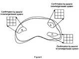
- FIG. 4is an object process diagram of one embodiment of an image guidance system incorporating first and second knowledge-based systems.
- FIG. 5illustrates application of regions of interest to a prostate image by the first knowledge-based system.
- FIG. 6illustrates analysis of regions of interest in the prostate image of FIG. 5 by the second knowledge-based system.
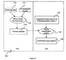
- FIG. 7is an object process diagram of the second knowledge-based system.
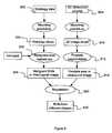
- FIG. 8is an offline model training system for the second knowledge-based system.
- FIG. 9is a tumor ground truth generation procedure for the second knowledge-based system.
- FIG. 10is a registration procedure for the second knowledge-based system.
- FIG. 11is a feature extraction procedure for the second knowledge-based system.
- FIG. 12is an online classification system for the second knowledge-based system.
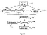
- FIG. 14illustrate a parallel work flow for the online classification system of the second knowledge-based system.
- FIG. 15illustrate a parallel work flow for feature extraction for the online classification system of the second knowledge-based system.
- the tissue culture/biopsyis assisted by an image guidance system 30 .
- the image guidance system 30provides confirmed tissue culture locations so the urologists can perform tissue culture extraction in these locations.
- the image guidance system 30utilizes initial biopsy targeting information provided by a first knowledge-based system 34 , where targeting information is confirmed by a second knowledge-based or learning based system 36 .
- the first system 34is operative to identify suspicious regions and the second knowledge-based system 36 is used to confirm that the suspicious regions are actually of interest. Further, the system may allow for validating that the extracted tissue is in correct region, location and position.
- an ultrasound probe 10has a biopsy needle assembly 12 attached to its shaft inserted into the rectum from the patient's anus.
- the illustrated probe 10is an end-fire transducer that has a scanning area of a fan shape emanating from the front end of the probe (shown as a dotted outline).
- the probe handleis held by a robotic arm (not shown) that has a set of position sensors 14 .
- These position sensors 14are connected to the computer 20 of the imaging system 30 via an analog to digital converter.
- the computer 20has real-time information of the location and orientation of the probe 10 in reference to a unified Cartesian (x, y, z) coordinate system.
- the ultrasound probe 10sends signal to the image guidance system 30 , which may be connected to the same computer (e.g., via a video image grabber) as the output of the position sensors 14 .
- this computeris integrated into the imaging system 30 .
- the computer 20therefore has real-time 2D and/or 3D images of the scanning area in memory 22 .
- the image coordinate system and the robotic arm coordinate systemare unified by a transformation.
- a prostate surface 50e.g., 3D model of the organ
- biopsy needle 52are simulated and displayed on a display screen 40 with their coordinates displayed in real-time.
- a biopsy needlemay also be modeled on the display, which has a coordinate system so the doctor has the knowledge of the exact locations of the needle and the prostate.
- the computer systemruns application software and computer programs which can be used to control the system components, provide user interface, and provide the features of the imaging system.
- the softwaremay be originally provided on computer-readable media, such as compact disks (CDs), magnetic tape, or other mass storage medium. Alternatively, the software may be downloaded from electronic links such as a host or vendor website. The software is installed onto the computer system hard drive and/or electronic memory, and is accessed and controlled by the computer's operating system. Software updates are also electronically available on mass storage media or downloadable from the host or vendor website.
- the softwareas provided on the computer-readable media or downloaded from electronic links, represents a computer program product usable with a programmable computer processor having computer-readable program code embodied therein.
- the softwarecontains one or more programming modules, subroutines, computer links, and compilations of executable code, which perform the functions of the imaging system.
- the userinteracts with the software via keyboard, mouse, voice recognition, and other user-interface devices (e.g., user I/O devices) connected to the computer system.
- the first knowledge-based system 34is a statistical atlas that identifies areas or regions of interest (ROIs) on a prostate of a patient.
- ROIsareas or regions of interest
- a shape model including statistical informationmay be generated that may subsequently be fit to a patient prostate image.
- 3-D ultrasound images of multiple prostatesare acquired 102 using, for example a TransRectal UltraSound (TRUS) system.
- TRUSTransRectal UltraSound
- the acquired imagesmay then be converted to 3-D orthogonal voxel data (e.g., ultrasound volumes) having equal resolution in all three dimensions.
- 3-D individual imagesmay then be represented as a set of two-dimension images.
- such a proceduremay be performed on a plurality of patients to obtain a database of ultrasound volumes, which may be utilized to, generate a shape model.
- the ultrasound volumesmay be utilized to train a shape model.
- the segmented surfacesmust be labeled. That is, corresponding structures within each segmented surface must be labeled to a common reference frame. This is referred to as a registration process 104 . See FIG. 2 .
- each of the ultrasound volumesare marked by an expert (e.g., histologist) in feature rich regions or regions that distinguish the shape of the surface. The marked points are called landmarks, and they are correspondingly marked in all of the images of the training data/ultrasound volume database.
- a process for training the shape modelis performed 108 .
- the training imagesreflect a variety of different geometrical prostate shapes. These different shapes must be taken into account in training the system.
- an average shapeis created from the training images in the form of a mean shape vector 110 .
- creating the average prostate shapeinvolves labeling a set of feature points corresponding to prostate features/landmarks depicted in each training image in the training set of ultrasound volumes. The locations of the labeled feature points from a training images are used to form vector shapes 108 . The average of all the vector shapes 108 is then computed to produce a mean vector shape 110 that represents the average prostate shape. More specifically, a top percentage of Eigen Vectors are selected that account for more than 95% variance of the entire set of images. Accordingly, the projections on the selected Eigen Vectors can then be utilized to align the shape model (e.g., mean shape) to any other shape.
- the shape modele.g., mean shape
- a mean shape and its principal mode of variationare defined 110 . These modes of variation can be utilized to fit the mean prostate shape to a prostate image acquired from a patient. Registration of the model to any shape resembling the training shape now becomes a straightforward mathematical process.
- the projectioncan be either directly optimized to maximize the similarity between the given shape and the model or the model can be allowed to “warp” freely and may be constrained by requirements of the model that would prevent the model from warping into shapes that do not resembles a prostate.
- Statistical information collectionentails the collection of histology data 120 , which are outlined and labeled 122 . See FIG. 2 .
- prostate cancer locationsare identified and mapped for a large group of patient data. These samples are collected and used to compile statistics on the presence of cancer locations.
- Reference to the database of images whose cancer characteristics are fully knownis referred to as ground truth data.
- This ground truth datamay be utilized to generate a look-up-table or LUT/map/atlas that indicates the probability of various regions of developing cancer.
- These ground truths imagesmay be generated from histological data including histological, slices from actual prostates and/or histological data identified from individual prostate images.
- the ground truth imagesare all mapped to a common anatomical frame 126 and contain labels that mark every location of the prostate, i.e. whether cancer is present or not. Such labels may be selected by a histologist 124 . Cancer probability maps/atlases are then computed from this data. These maps/atlases can be used for biopsy guidance.
- Data from separate prostatesis labeled to a common reference frame 126 such that the data may be incorporated into a map/atlas that may be utilized to identify areas within a prostate for a given patient.
- labelingmay include selecting a volume as a common volume of reference for a set of image volumes.
- Each of the remaining volumesmay be registered to the chosen common volume of reference so as to create an atlas 128 .
- special coordinates of cancer in each of the remaining image volumesare mapped onto the atlas coordinates in the atlas by transformation that registers the corresponding image volume to the atlas.
- prostate regions that contain cancermay be identified. For instance, if a plurality of the histological samples of different prostates include cancer in a common area, a region of interest of that region may be identified.
- the ROImay be a area that may represent an optimal target region for biopsy to identify cancer within that region of the prostate.
- a map/atlasmay be aligned 128 with the mean shape of the shape model discussed above. That is, statistical information of the map/atlas (e.g., regions of increased probability of cancer) may be incorporated into the shape model.
- This shape model and corresponding statistical information 130may then be fit to an image of a prostate of a patient in an online procedure. Accordingly, statistical information associated with the regions having a high incidence of cancer may be overlaid onto and/or into the image of the prostate of the patient. Accordingly, these regions may be targeted for biopsy.
- the online portioninvolves acquiring a current image 140 for a patient.
- the ultrasound imageOnce the ultrasound image is acquired it may be segmented 142 to identify the surface of the 3-D volume/capsule 144 and/or the boundaries of individual images (e.g., 2-D or 3-D images).
- Such segmentationmay be performed in any known manner.
- One such segmentation methodis provided in co-pending U.S. patent application Ser. No. 11/615,596, entitled “Object Recognition System for Medical Imaging” filed on Dec. 22, 2006, the contents of which are incorporated by reference herein.
- the segmented imageis then provided for combination with the shape model 146 in order to align the map/atlas information with the acquired image. Biopsy locations may then be identified 148 .
- FIGS. 3A-3Dgraphically illustrate the overall process. Though illustrated as 2D figures, it will be appreciated that the shape model, prostate image and statistical regions (e.g., ROI's) discussed herein may be three dimensional. Accordingly, the statistical information may be displayed on and/or within the prostate image.
- the shape model 202is provided. See FIG. 3A .
- Statistical information 200e.g., ground truth data
- a current patiente.g., based on demographics, PSA, etc
- FIG. 3Ba completely defined geometrical deformations shape model 204 including statistical information is provided. See FIG. 3B .
- the deformation shape model 204may be based on a set of Eigen vectors that allow the model 204 to only be fitted in ways allowed by predetermined limitations of the model.
- the modelmay then be applied (e.g., fit) to an acquired ultrasound prostate image 206 . See FIG. 3C .
- the result of this fitting procedureis also the transfer of statistical information to the prostate image 206 of the patient. That is, the statistical information may be applied to the prostate image 206 of the patient to provide a combined image with statistical data 208 . See. FIG. 3D .
- the combined image 208may be used to define regions of interest on the prostate of the current patient that have, for example, higher likelihood of cancer. Accordingly, a urologist may target such regions for biopsy.
- the present inventionutilizes a second knowledge-based system to confirm the desirability of performing biopsy on the suggested region.
- the second knowledge-based systemperforms a texture/textural analysis and classification of the suggested biopsy regions to confirm whether a biopsy should be taken from the suggested regions.
- prostate imagesare acquired 404 with a 3D ultrasound imaging system 406 to generate a 3-D volume 408 .
- the acquired data 408is then provided to a first knowledge-based system 410 and fused using a multi-modality image data set or warped using a knowledge-based system such as ATLAS.
- This first knowledge-based system 410is a guidance system without any confirmation that provides suggested biopsy regions 412 .
- a second knowledge-based system 414may perform an efficient image textural analysis and classification for those initial suggested biopsy regions.
- the confirmed regions confirmed 416 (for biopsy) by the second knowledge-based systemcan provide urologists improved guidance for a biopsy procedure 418 where tissue samples are extracted 420 .
- FIGS. 2 and 5several high probability suspicious regions A-C where biopsy is suggested are marked out in a prostate image with the help of the first knowledge-based system.
- a statistical atlas of the spatial distribution of prostate canceris constructed from histological images of a patient database.
- a probabilistic optimization frameworkis employed to optimize the biopsy strategy; finally, the optimized biopsy strategy generated in the atlas is mapped to a new patient's image. Accordingly, suggested biopsy regions A-C can be marked out.
- FIG. 6illustrated one embodiment of the second knowledge-based system.
- the suggested biopsy regions A-C provided by the first knowledge-based systemare analyzed by the second knowledge-based system, which provides a confirmation whether those regions are likely cancerous or not.
- Such analysismay be limited to the regions of interest to limit the computational requirements of the system. Further, such analysis may be performed on a pixel by pixel basis, though this is not a requirement.
- a process 700 of the second knowledge-based systemis described.
- inputs to the systeminclude histology data 712 and 3D ultrasound prostate images 714 .
- the histology data and the ultrasound images in the patient databaseare used 716 to generate tumor ground truth information and train a classifier 718 .
- the suggested biopsy regions 722 provided by the first knowledge-based system in a new patient's ultrasound imageare classified 724 and confirmed 726 .
- FIG. 8shows the offline model training system 710 for the second knowledge-based system where histology data 802 and 3D ultrasound images 804 are used to generate tumor ground truth information 806 .
- regions of interest (ROIs) 808from different classes of the ground truth tumor information may be identified.
- a feature extraction process 810is performed on each different class to generate extracted feature vectors 812 . That is, cancerous region and benign region in the training images are known.
- the features to describe different ROIsare extracted.
- the best feature setsare, selected through feature selection procedure 814 .
- the feature vectors 816 from each ROIare used as inputs in a classifier training process 818 to produce trained classifiers 820 that the second knowledge-based system may utilize to confirm or eliminate suspect regions identified by the first knowledge-based system.
- the processis based on a training database including histology data 802 and prostate ultrasound images 804 .
- the overall scheme for the presented utilitycan be summarized as follows: initially, in the training dataset, the 3D volumes 804 are mounted into 2D image slices 910 . The prostate boundary in each 2D ultrasound image is segmented 912 by a semi-automatic or automatic segmentation algorithm.
- the histology data 802is also mounted to 2D sliced 904 with tumor regions marked out 906 by urologists are used as references, assisting by a registration procedure 920 , the corresponding regions in the prostate ultrasound images can be found.
- the cancerous regions and benign regions (ROIs) in the training imagesare known.
- a set of feature vectors to describe different ROIsis extracted by image processing algorithms.
- the feature vectorsinclude statistical features, gradient features and Gabor filtering features. The features with the most discriminant power are selected through a feature selection algorithm.
- each ROI with known class labelis digitized by a feature vector. They are used as training samples to train a classifier. The best parameters associated with a classifier are determined through the training procedure.
- Thisis offline model training.
- the knowledge-based system- 1provides initial suggested biopsy regions (ROIs) in the ultrasound image.
- the feature vectorsare then extracted in each of these ROIs.
- the trained classifier from offline trainingcan determine if these ROIs are truly cancerous or not. This is online classification procedure.
- the knowledge-based system- 2works as a confirmation sub-system. So the Urologists can do tissue culture in those confirmed biopsy regions.
- a genetic algorithm (GA) approachis used.
- PDMpoint distribution model
- the PDMis a model of object contour that can be defined with certain number of parameters. The parameter value varies in the certain ranges in which result different shapes of contours.
- the main advantage of GAsis its adaptive search techniques designed to search for near-optimal solutions of large-scale optimization problems with multiple local maxima. GAs are independent of initialization parameters and can efficiently optimize functions in large search spaces. Composing PDM and GAs can efficiently optimize the search space and adjust the best contour fit to the prostate boundary. By initial data analysis, it was confirmed that the use of PDM and GAs techniques can lead to obtaining prostate contours in the real time.
- a level set strategymay be used for contour estimation.
- An automated algorithmis proposed to delineate the boundary of the prostate. This provides a methodology that models the prostate images as combination of homogeneous regions with different gray levels, and minimizes the energy functional based on the regional information of the image.
- the urologistputs few initial points near the prostate capsule and computer then automatically estimates the final boundary.
- the computer algorithmmodels the prostate images as combination of homogeneous regions with different gray levels, and minimizes the energy functional based on the regional information of the image.
- This strategyis implemented in a level set framework, where, the contour is represented implicitly in the level set function.
- a finite difference method embedded in a steepest descent frameworkis used to compute the stabilized boundary in the narrow band search region.
- GVFgradient vector flow
- the GVF snakesreplace the standard external force in the traditional snakes with a static external force which does not change with time or depend on the position of the snake itself.
- the new static external forceis called gradient vector field.
- GVF snakesfirst calculate of a field of forces, called the GVF forces, over the image.
- the GVF forcesare calculated by applying generalized diffusion equations to both components of the gradient of an image edge map.
- the GVF forcesare derived from a diffusion operation, they tend to extend very far away from the object.
- FIG. 10shows the registration procedure for the second knowledge-based system.
- the main goalis to find correspondences between a histological image slice 1002 and a corresponding 2D ultrasound image slice 1004 , thus providing ground truth to train a classifier.
- Image registrationestablishes a common frame of reference for a meaningful comparison between the two images.
- Image registrationis often posed as an optimization problem which minimizes an objective function representing the difference between two images to be registered.
- the symmetric squared intensity differenceis chosen as the driving function.
- regularization constraintsmay be applied so that the deformation follows a model that matches closely with the deformation of real-world objects.
- the regularizationis applied in the form of bending energy and inverse-consistency cost.
- Inverse-consistencyimplies that the correspondence provided by the registration in one direction matches closely with the correspondence in the opposite direction.
- Most image registration methodsare uni-directional and therefore contain correspondence ambiguities originating from choice of direction of registration.
- the forward and reverse correspondencesare computed simultaneously and bound together through an inverse consistency cost term.
- the inverse consistency cost termassigns higher cost to transformations deviating from being inverse-consistent. While inverse consistency minimizes the correspondence ambiguity, it also helps the transformation perform better by forcing it out of local minima.
- the cost function for performing image registration over the imageis calculated 1006 , in which the correspondence is estimated in both directions such that the registration is inverse consistent. Inverse consistency is a desirable property of transformation and ensures that there is no correspondence ambiguity if the direction of registration is reversed.
- Lis a differential operator and the second term in Eq. (1) represents an energy function.
- ⁇ , ⁇ and ⁇are weights to adjust relative importance of the cost function.
- the first termrepresents the symmetric squared intensity cost function and represents the integration of squared intensity difference between deformed reference image and the target image in both directions.
- the second termrepresents the energy regularization cost term and penalizes high derivatives of u(x).
- the last termrepresents the inverse consistency cost function, which penalizes differences between transformation in one direction and inverse of transformation in opposite direction.
- the total cost 1008is computed as a first step in registration.
- ⁇ i (x)represents the value of B-spline at location x, originating at index i.
- cubic B-splinesare used.
- a gradient descent schemeis implemented based on the above parameterization.
- the total gradient costis recalculated 1014 with respect to the transformation parameters in every iteration.
- the transformation parametersare updated using the gradient descent update rule. Images are deformed into shape of one another using the updated correspondence and the cost function and gradient costs are calculated until convergence defining ROI's for different classes 1018 .
- the registrationis performed hierarchically using, a multi-resolution strategy in both, spatial domain and in domain of basis functions.
- the registrationmay be performed at 1 ⁇ 4 th , 1 ⁇ 2 and full resolution using knot spacing of 8, 16 and 32.
- the multi-resolution strategyhelps in improving the registration by matching global structures at lowest resolution and then matching local structures as the resolution is refined.
- FIG. 11shows a feature extraction procedure of the offline model training.
- a set of features 1104 A-Dare extracted from each ROI 1102 .
- the features chosen hereinclude the following: “A” features: first order statistical features; “B” features: second order statistical features; “C” features: gradient features; “D” features: Gabor bank filter features.
- a variety of extracted featuresare specifically suitable to texture analysis of prostate ultrasound image. The plan is to measure features of the region of interest and then use these features to determine class membership including, for instance, whether it is benign or malignant.
- a ROI to be analyzedC, is rectangular and has N x rows and N y columns. See, e.g., FIG. 6 .
- L x⁇ 1, 2, . . . , N x ⁇ be the rows
- L y⁇ 1, 2, . . . , N y ⁇ be the columns.
- NN x ⁇ N y
- the first-order texture featuresinclude maximum, minimum, mean and standard deviation in a ROI (addresses the statistical distribution of digital gray scale values to compare cancerous and non-cancerous biopsy sites within a gland) are extracted.
- F 1Max u , ⁇ c ⁇ [ f ⁇ ( u t ) ] ( 3 )
- F 2Min u , ⁇ c ⁇ [ f ⁇ ( u t ) ] ( 4 )
- Gray level co-occurrence Matrixproposed by R. M. Haralick, K. Shanmugan, and I. Dinstein, “Textural features for image classification,” IEEE Trans. Syst. Man, Cybern., Vol. SMC-3, pp. 610-621, 1973, the contents of which are incorporated herein can be used to compute second-order features which have perceptual meaning. It is an indication of how different combinations of gray levels exist in a portion of the image.
- GLCMis generated from a small square window of the image. Within the window, unordered pairs of pixels are examined that are separated by a given distance and are oriented to each other by a given angle.
- the window sizehere are 3 ⁇ 3 and 5 ⁇ 5 pixels, and angles of 0, 45, 90, or 135 are used.
- An entire imagecan be analyzed by moving the window across the image in an overlapping manner, advancing one pixel column to the right, then one pixel row downward at a time.
- the ROI Ccan be represented as a function that assigns some gray level in G to each pixel or pair of coordinates in L x ⁇ L y .
- the texture-context informationis specified by the matrix of relative frequencies P ij with two neighboring pixels separated by distance d occur on the image, one with gray level i and the other with gray level j.
- Such matrices of gray-level co-occurrence frequenciesare a function of the angular relationship and distance between the neighboring pixels.
- ⁇ x⁇ i ⁇ ⁇ j ⁇ i ⁇ ⁇ • ⁇ ⁇ p ⁇ ( i , j )
- ⁇ y⁇ i ⁇ ⁇ j ⁇ j ⁇ ⁇ • ⁇ ⁇ p ⁇ ( i , j )
- ⁇ x⁇ i ⁇ ⁇ j ⁇ ( i - ⁇ x ) 2 ⁇ • ⁇ ⁇ p ⁇ ( i , j )
- ⁇ y⁇ i ⁇ ⁇ j ⁇ ( j - ⁇ y ) 2 ⁇ • ⁇ ⁇ p ⁇ ( i , j ) .
- a set of four features,is constructed from the GLCM which are: contrast, entropy, energy, homogeneity. The features are as follows, Energy: provides the sum of squared elements in the GLCM;
- Homogeneitymeasures the closeness of the distribution of elements in the GLCM to the GLCM diagonal.
- Gradient operatorsare used here to characterize micro-textures well.
- 2D directional gradient and 2D gradient magnitude operatorsare used to separate faint and not well-defined textural differences between normal and pathological 2D structures in the prostate.
- the Gabor filter bankis also used to capture image, features in multi-scales and multi-orientations.
- the Gabor functionis the modulation of a Gaussian with a sinusoid.
- 2D Gabor filterhas been widely used for various pattern recognition problems.
- the mother function of the two-dimensional Gabor filteris
- this strategyallows for extracting a variety of features 1106 specifically suitable to texture analysis of prostate ultrasound image, and a large number of features' combination from different filters ensures capture of a large range of information from the datasets.
- the next stepis feature selection 814 .
- the goal of feature selectionis to choose the best feature set to characterize the property of ROIs. Once a number of features are obtained, the next question is how to select the most important features so as to reduce their number and at the same time retain as much as possible of their class discriminant powers. Feature selection is crucial for machine learning. If some features are with little discriminant power, the subsequent design of a classifier may lead to poor performance. This feature selection is to ensure a large number of features extracted are truly useful to describe the image properties from different classes. In this application, a method is applied which called mutual information feature selection (MIFS). See R. Battiti, “Using mutual information for selecting features in supervised neural net learning,” IEEE Trans. Neural Networks, Vol. 5, pp. 537-550, 1994, which is incorporated by reference herein.
- MIFSmutual information feature selection
- MIFSis a powerful tool for feature selection compared with other existing methods for the following reasons: (1) MIFS not only evaluates the information content of each feature with respect to the output class, but also with respect to each of the other features; (2) the traditional feature selection for classification is classifier-dependent. In contrast, MIFS is a classifier-independent technique. That means, the best feature subset is chosen regardless of the chosen classifier.
- MIFScan be explained as follows: denote X as a random variable, describing a texture feature and C is a random variable, describing the class. Then the mutual information I(C; X) is a measure of the amount of information that feature X contains about the class C. Thus mutual information provides a criterion for measuring the effectiveness of a feature for the separation of the two classes. Interdependence between feature values and classes is proportional to the value of I(C; X) and the interdependence among the features is, denoted by I(X 1 ; X 2 ) that should be minimized to avoid selecting two or more similar features. Therefore, the objective is to maximize I(C; X) and minimize I(X 1 ; X 2 ).
- the entropy H(C)depends mainly on classes.
- the mutual information, I(C; X)is maximum when the class is totally dependant on the feature, while it is minimum when the class and the feature are totally independent.
- I(X 1 ; X 2 )H ( X 2 ) ⁇ H ( X 2 ⁇ X 1 )
- MIFS algorithmis used here to select features from the combined set of features.
- classifier trainingis performed offline.
- vector x ⁇ R ndenote a feature vector to be classified (here the feature vector is obtained after feature extraction and selection), and letting scalar d denote its class label (i.e. d ⁇ 1 ⁇ ).
- the problemthen becomes how to determine a classifier ⁇ (x) (i.e., a decision function) that can correctly classify an input pattern (not necessarily from the training set).
- This applicationuses two methods for classification.
- NNneural networks
- An NNis an information-processing system that is based on generalization of human cognition or neural biology. It is composed of many artificial neurons that are linked together according to a specific network architecture. The objective of the neural network is to transform the inputs into meaningful outputs.
- a typical neural networkhas three layers: input layer, hidden layer and output layer, which are interconnected by modifiable weights, represented by links between layers.
- Neural networkscan be considered as nonlinear function approximating tools (i.e., linear combinations of nonlinear basis functions), where the parameters of the networks should be found by applying optimization methods. In general it is enough to have a single hidden layer neural network to learn the approximation of a nonlinear function.
- a method based on gradient descentis used in the error-back propagation algorithm for training such multilayer networks. It is a powerful method for classification and has been applied widely in other areas for computer aided diagnosis.
- SVMsupport vector machines
- SVMis a constructive learning procedure rooted in statistical learning theory. It is based on the principle of structural risk minimization, which aims at minimizing the bound on the generalization error (i.e., error made by the learning machine on data unseen during training) rather than minimizing the mean square error over the data set.
- an SVMtends to perform well when applied to data outside the training set. It has been demonstrated that it can outperform many other existing methods in many applications.
- SVMis applied to classify the cancerous regions and non-cancerous regions in prostate ultrasound images.
- the cost function in (17)constitutes a balance between the empirical risk (i.e., the training errors reflected by the second term) and model complexity (the first term).
- the parameter Ccontrols this trade-off.
- the purpose of using model complexity to constrain the optimization of empirical riskis to avoid over fitting, a situation in which the decision boundary too precisely corresponds to the training data, and thereby fails to perform well on data outside the training set.
- a training sample (x i ,d i )is called a support vector when d i ⁇ SVM (x i ) ⁇ 1.
- the SVM function ⁇ SVM (x)can be rewritten in (16) in a kernel form as follows
- the decision functioncan be directly rewritten through the kernel function K(.,.) without the need to specifically addressing the underlying mapping ⁇ (.).
- two kernel typesare considered: polynomial kernels and Gaussian radial basis functions (RBF). These are among the most commonly used kernels in SVM research, and are known to satisfy Mercer's condition. They are defined as follows:
- a 10-fold cross validation procedureis applied during training to choose the right parameters for the two classifiers.
- the 10-fold cross validationfirst, all the data is randomly divided into 10 equal-sized subsets.
- the classifier modelis trained 10 times; during each time one of the 10 subsets is held out in turn while the remaining 9 subsets are used to train the classifier; the trained classifier is then used to classify the held-out subset, and the classification result is recorded.
- the classification results for the 10 subsetsare averaged to obtain an estimate of the generalization error of the classifier model.
- the online classification system for the second knowledge-based systemis described.
- the suggested biopsy regions A-C in an ultrasound imageare obtained 1202 from the first knowledge-based system, then the same features selected from offline model training procedure are extracted 1204 from those ROIs.
- the extracted feature vectors 1206are then fed into a classification process 1208 with the trained classifiers 1210 to decide whether the region is cancerous or not. This is a confirmation procedure 1212 ; afterwards, the confirmed biopsy regions (e.g., regions A and C in FIG. 13 ) are obtained and can give urologists a better guidance to do biopsy.
- This classification systemis an online system and can be used real-time to assist urologists in prostate cancer diagnosis.
- the workflowmay also be designed to enhance the speed of the system. For instance, as illustrated in FIG. 14 , parallel processing may be performed on different suggested regions.
- the first knowledge-based systemidentifies N suspicious regions 1402 A-N in the prostate and they are regions of interest (ROIs) which are suggested to do biopsy.
- the online classification system 1404 of the second knowledge-based systemdoes not require the examination of the entire image. It only confirms these suspicious regions and decides whether they are true malignant or not. It is efficient. Instead of confirming them one by one, the N regions are fed into the online classification system 1404 simultaneously, such that there are N parallel classification systems. In this way, N suggested ROIs can be classified and confirmed 1406 A-N at the same time to show the urologists the final confirmed biopsy locations.
- feature extraction for each ROImay be performed in parallel. That is, for each suggested biopsy region 1502 , M features may be used to describe a ROI. These M features are selected from the feature selection step in the offline model training system. The same M features have been used to train the classifier in the offline system. Then in the online classification system, M features need to be extracted 1504 A-M for each ROI 1502 .
- a multi-threading techniqueis applied to extract M features for each ROI.
- M parallel filtersare applied to compute these M features simultaneously by multi-threading technique. As shown in FIG. 15 , in this way, we can save computation time.
- multi-resolution Gabor filteris applied instead of traditional Gabor filter.
- the concept of multi-resolution with parameter selectionis used.
- the computation timecan be reduced by diminishing the image size according to several different sets of parameters.
- M featuresare obtained for each ROI, this feature vector 1506 (M dimensional) is used as inputs to the classifier process 1508 within the trained classifier 1510 , then the output 1512 (whether it is true malignant or not) can be computed in real time. Since we have N parallel classification systems, the confirmed results of these N regions are known simultaneously.
- the online classification systemmay be implemented on a GPU based framework, which may speed up computation to a factor of 30 compared with the traditional CPU framework.
Landscapes
- Engineering & Computer Science (AREA)
- Physics & Mathematics (AREA)
- Theoretical Computer Science (AREA)
- Computer Vision & Pattern Recognition (AREA)
- General Physics & Mathematics (AREA)
- Health & Medical Sciences (AREA)
- Life Sciences & Earth Sciences (AREA)
- Medical Informatics (AREA)
- General Health & Medical Sciences (AREA)
- Software Systems (AREA)
- Nuclear Medicine, Radiotherapy & Molecular Imaging (AREA)
- Radiology & Medical Imaging (AREA)
- Multimedia (AREA)
- Molecular Biology (AREA)
- Computing Systems (AREA)
- Surgery (AREA)
- Animal Behavior & Ethology (AREA)
- Biomedical Technology (AREA)
- Public Health (AREA)
- Veterinary Medicine (AREA)
- Pathology (AREA)
- Artificial Intelligence (AREA)
- Heart & Thoracic Surgery (AREA)
- Databases & Information Systems (AREA)
- Evolutionary Computation (AREA)
- Biophysics (AREA)
- Quality & Reliability (AREA)
- Ultra Sonic Daignosis Equipment (AREA)
- Image Analysis (AREA)
- Measuring And Recording Apparatus For Diagnosis (AREA)
Abstract
Description
where, I1(x) and I2(x) represent the intensity of image at location x, represents the domain of the image. hi,j(x)=x+ui,j(x) represents the transformation from image Iito image Ijand u(x) represents the displacement field. L is a differential operator and the second term in Eq. (1) represents an energy function. σ, ρ and χ are weights to adjust relative importance of the cost function.
where, βi(x) represents the value of B-spline at location x, originating at index i. In the presented registration method, cubic B-splines are used. A gradient descent scheme is implemented based on the above parameterization. The total gradient cost is recalculated1014 with respect to the transformation parameters in every iteration. The transformation parameters are updated using the gradient descent update rule. Images are deformed into shape of one another using the updated correspondence and the cost function and gradient costs are calculated until convergence defining ROI's for
A set of four features, is constructed from the GLCM which are: contrast, entropy, energy, homogeneity. The features are as follows,
Energy: provides the sum of squared elements in the GLCM;
Contrast: measures the local variations in the GLCM;
Correlation: measures the joint probability occurrence of the specified pixel pairs;
Homogeneity: measures the closeness of the distribution of elements in the GLCM to the GLCM diagonal.
F10=Gabor(ƒ(u)) (13)
I(C;X)=H(C)−H(C|X), (14)
Where the entropy H(C) measures the degree of uncertainty entailed by the classes, the conditional entropy H(C|X) measures the degree of uncertainty entailed by the set of classes C given the set of feature values X. The entropy H(C) depends mainly on classes. The mutual information, I(C; X), is maximum when the class is totally dependant on the feature, while it is minimum when the class and the feature are totally independent. The mutual information among different features I(X1; X2) is calculated as follows:
I(X1;X2)=H(X2)−H(X2−X1) (15)
The MIFS algorithm is used here to select features from the combined set of features.
ƒSVM(x)=wTΦ(x)+b (16)
where parameters w, b are determined from the training data samples. This is accomplished through minimization of the following so-called structural risk function:
- subject to diƒSVM(xi)≧1−ξi, ξi≧0; i=1, 2, . . . , N,
where C is a user-specified, positive parameter, ξiare slack variables. In particular, when the two classes are separable, minimizing the structural risk in (17) amounts to maximizing the separating margin between the two classes.
- subject to diƒSVM(xi)≧1−ξi, ξi≧0; i=1, 2, . . . , N,
where si, i=1, 2, . . . , Ns, denote the support vectors. In general, support vectors constitute only a small fraction of the training samples {xi, i=1, 2, . . . , N}.
K(x,y)=(xTy+1)p (19)
- where p>0 is a constant that defines as the kernel order.
- where σ>0 is a constant that defines the kernel width.
Claims (7)
Priority Applications (1)
| Application Number | Priority Date | Filing Date | Title |
|---|---|---|---|
| US12/014,635US8175350B2 (en) | 2007-01-15 | 2008-01-15 | Method for tissue culture extraction |
Applications Claiming Priority (2)
| Application Number | Priority Date | Filing Date | Title |
|---|---|---|---|
| US88494107P | 2007-01-15 | 2007-01-15 | |
| US12/014,635US8175350B2 (en) | 2007-01-15 | 2008-01-15 | Method for tissue culture extraction |
Publications (2)
| Publication Number | Publication Date |
|---|---|
| US20080170770A1 US20080170770A1 (en) | 2008-07-17 |
| US8175350B2true US8175350B2 (en) | 2012-05-08 |
Family
ID=39617828
Family Applications (1)
| Application Number | Title | Priority Date | Filing Date |
|---|---|---|---|
| US12/014,635Active2030-12-08US8175350B2 (en) | 2007-01-15 | 2008-01-15 | Method for tissue culture extraction |
Country Status (1)
| Country | Link |
|---|---|
| US (1) | US8175350B2 (en) |
Cited By (8)
| Publication number | Priority date | Publication date | Assignee | Title |
|---|---|---|---|---|
| US8406844B2 (en) | 2002-03-06 | 2013-03-26 | Tomotherapy Incorporated | Method for modification of radiotherapy treatment delivery |
| WO2015008279A1 (en)* | 2013-07-15 | 2015-01-22 | Tel Hashomer Medical Research Infrastructure And Services Ltd. | Mri image fusion methods and uses thereof |
| US9443633B2 (en) | 2013-02-26 | 2016-09-13 | Accuray Incorporated | Electromagnetically actuated multi-leaf collimator |
| CN109259801A (en)* | 2018-09-12 | 2019-01-25 | 深圳开立生物医疗科技股份有限公司 | A kind of shearing wave elastograph imaging method and device |
| CN111110332A (en)* | 2020-01-19 | 2020-05-08 | 汕头市超声仪器研究所有限公司 | Optimization method for puncture needle development enhanced image |
| US10716544B2 (en) | 2015-10-08 | 2020-07-21 | Zmk Medical Technologies Inc. | System for 3D multi-parametric ultrasound imaging |
| US11257188B2 (en)* | 2019-01-10 | 2022-02-22 | Fujifilm Healthcare Corporation | Ultrasonic imaging device and image processing method |
| US12011222B2 (en) | 2019-05-02 | 2024-06-18 | Avenda Health, Inc. | Interlock to define a fixed spatial relationship between medical instruments |
Families Citing this family (33)
| Publication number | Priority date | Publication date | Assignee | Title |
|---|---|---|---|---|
| US7088872B1 (en)* | 2002-02-14 | 2006-08-08 | Cogent Systems, Inc. | Method and apparatus for two dimensional image processing |
| US8131477B2 (en) | 2005-11-16 | 2012-03-06 | 3M Cogent, Inc. | Method and device for image-based biological data quantification |
| US8425418B2 (en)* | 2006-05-18 | 2013-04-23 | Eigen, Llc | Method of ultrasonic imaging and biopsy of the prostate |
| WO2008017999A1 (en)* | 2006-08-08 | 2008-02-14 | Koninklijke Philips Electronics N.V. | Registration of electroanatomical mapping points to corresponding image data |
| US8064664B2 (en)* | 2006-10-18 | 2011-11-22 | Eigen, Inc. | Alignment method for registering medical images |
| US7804989B2 (en)* | 2006-10-30 | 2010-09-28 | Eigen, Inc. | Object recognition system for medical imaging |
| US20080161687A1 (en)* | 2006-12-29 | 2008-07-03 | Suri Jasjit S | Repeat biopsy system |
| US8175350B2 (en) | 2007-01-15 | 2012-05-08 | Eigen, Inc. | Method for tissue culture extraction |
| US7856130B2 (en)* | 2007-03-28 | 2010-12-21 | Eigen, Inc. | Object recognition system for medical imaging |
| US8275179B2 (en)* | 2007-05-01 | 2012-09-25 | 3M Cogent, Inc. | Apparatus for capturing a high quality image of a moist finger |
| US8571277B2 (en) | 2007-10-18 | 2013-10-29 | Eigen, Llc | Image interpolation for medical imaging |
| US7942829B2 (en)* | 2007-11-06 | 2011-05-17 | Eigen, Inc. | Biopsy planning and display apparatus |
| EP2225679A1 (en)* | 2007-12-18 | 2010-09-08 | Koninklijke Philips Electronics N.V. | Consistency metric based image registration |
| WO2009111580A2 (en)* | 2008-03-04 | 2009-09-11 | Tomotherapy Incorporated | Method and system for improved image segmentation |
| US20100014755A1 (en)* | 2008-07-21 | 2010-01-21 | Charles Lee Wilson | System and method for grid-based image segmentation and matching |
| US8218906B2 (en)* | 2008-08-20 | 2012-07-10 | Hankuk University Of Foreign Studies Research And Industry-University Cooperation Foundation | Image registration evaluation |
| US8693788B2 (en)* | 2010-08-06 | 2014-04-08 | Mela Sciences, Inc. | Assessing features for classification |
| US8879800B2 (en)* | 2011-06-15 | 2014-11-04 | Honeywell International Inc. | Quality driven image processing for ocular recognition system |
| US9058647B2 (en)* | 2012-01-16 | 2015-06-16 | Canon Kabushiki Kaisha | Information processing apparatus, information processing method, and storage medium |
| EP2826019B1 (en)* | 2012-03-15 | 2016-05-18 | Koninklijke Philips N.V. | Multi-modality deformable registration |
| US20150065868A1 (en)* | 2012-04-02 | 2015-03-05 | The Research Foundation for the State University New York | System, method, and computer accessible medium for volumetric texture analysis for computer aided detection and diagnosis of polyps |
| WO2014151808A1 (en)* | 2013-03-14 | 2014-09-25 | Volcano Corporation | Parallelized tree-based pattern recognition for tissue characterization |
| US9324155B2 (en)* | 2014-03-10 | 2016-04-26 | General Electric Company | Systems and methods for determining parameters for image analysis |
| WO2016193025A1 (en)* | 2015-06-04 | 2016-12-08 | Koninklijke Philips N.V. | System and method for precision diagnosis and therapy augmented by cancer grade maps |
| CA3004657A1 (en) | 2015-11-10 | 2017-05-18 | Exact Imaging, Inc. | A system comprising indicator features in high-resolution micro-ultrasound images |
| US10007971B2 (en)* | 2016-03-14 | 2018-06-26 | Sensors Unlimited, Inc. | Systems and methods for user machine interaction for image-based metrology |
| DE102017203248B3 (en)* | 2017-02-28 | 2018-03-22 | Siemens Healthcare Gmbh | Method for determining a biopsy position, method for optimizing a position determination algorithm, position determination unit, medical imaging device, computer program products and computer-readable storage media |
| US10699163B1 (en)* | 2017-08-18 | 2020-06-30 | Massachusetts Institute Of Technology | Methods and apparatus for classification |
| EP3550515A1 (en)* | 2018-04-05 | 2019-10-09 | Siemens Healthcare GmbH | Cross-modality image synthesis |
| WO2020002620A1 (en)* | 2018-06-29 | 2020-01-02 | Koninklijke Philips N.V. | Biopsy prediction and guidance with ultrasound imaging and associated devices, systems, and methods |
| CN112584738B (en)* | 2018-08-30 | 2024-04-23 | 奥林巴斯株式会社 | Recording device, image observation device, observation system, control method of observation system, and storage medium |
| WO2020168284A1 (en)* | 2019-02-15 | 2020-08-20 | The Regents Of The University Of California | Systems and methods for digital pathology |
| CN118096734B (en)* | 2024-04-23 | 2024-07-12 | 武汉名实生物医药科技有限责任公司 | Product quality monitoring method and system based on big data |
Citations (88)
| Publication number | Priority date | Publication date | Assignee | Title |
|---|---|---|---|---|
| US5224175A (en)* | 1987-12-07 | 1993-06-29 | Gdp Technologies, Inc. | Method for analyzing a body tissue ultrasound image |
| US5282472A (en) | 1993-05-11 | 1994-02-01 | Companion John A | System and process for the detection, evaluation and treatment of prostate and urinary problems |
| US5320101A (en) | 1988-12-22 | 1994-06-14 | Biofield Corp. | Discriminant function analysis method and apparatus for disease diagnosis and screening with biopsy needle sensor |
| US5383454A (en) | 1990-10-19 | 1995-01-24 | St. Louis University | System for indicating the position of a surgical probe within a head on an image of the head |
| US5398690A (en) | 1994-08-03 | 1995-03-21 | Batten; Bobby G. | Slaved biopsy device, analysis apparatus, and process |
| US5454371A (en) | 1993-11-29 | 1995-10-03 | London Health Association | Method and system for constructing and displaying three-dimensional images |
| US5531520A (en) | 1994-09-01 | 1996-07-02 | Massachusetts Institute Of Technology | System and method of registration of three-dimensional data sets including anatomical body data |
| US5562095A (en) | 1992-12-24 | 1996-10-08 | Victoria Hospital Corporation | Three dimensional ultrasound imaging system |
| US5611000A (en) | 1994-02-22 | 1997-03-11 | Digital Equipment Corporation | Spline-based image registration |
| US5810007A (en) | 1995-07-26 | 1998-09-22 | Associates Of The Joint Center For Radiation Therapy, Inc. | Ultrasound localization and image fusion for the treatment of prostate cancer |
| US5842473A (en) | 1993-11-29 | 1998-12-01 | Life Imaging Systems | Three-dimensional imaging system |
| WO2000014668A1 (en) | 1998-09-08 | 2000-03-16 | Catholic University Of America | Method and system for improved detection of prostate cancer |
| US6092059A (en) | 1996-12-27 | 2000-07-18 | Cognex Corporation | Automatic classifier for real time inspection and classification |
| US6171249B1 (en) | 1997-10-14 | 2001-01-09 | Circon Corporation | Ultrasound guided therapeutic and diagnostic device |
| US6238342B1 (en) | 1998-05-26 | 2001-05-29 | Riverside Research Institute | Ultrasonic tissue-type classification and imaging methods and apparatus |
| US6251072B1 (en) | 1999-02-19 | 2001-06-26 | Life Imaging Systems, Inc. | Semi-automated segmentation method for 3-dimensional ultrasound |
| US6261234B1 (en) | 1998-05-07 | 2001-07-17 | Diasonics Ultrasound, Inc. | Method and apparatus for ultrasound imaging with biplane instrument guidance |
| US6298148B1 (en) | 1999-03-22 | 2001-10-02 | General Electric Company | Method of registering surfaces using curvature |
| US6334847B1 (en) | 1996-11-29 | 2002-01-01 | Life Imaging Systems Inc. | Enhanced image processing for a three-dimensional imaging system |
| US6342891B1 (en) | 1997-06-25 | 2002-01-29 | Life Imaging Systems Inc. | System and method for the dynamic display of three-dimensional image data |
| US6351660B1 (en) | 2000-04-18 | 2002-02-26 | Litton Systems, Inc. | Enhanced visualization of in-vivo breast biopsy location for medical documentation |
| US6360027B1 (en) | 1996-02-29 | 2002-03-19 | Acuson Corporation | Multiple ultrasound image registration system, method and transducer |
| US6385332B1 (en) | 1999-02-19 | 2002-05-07 | The John P. Roberts Research Institute | Automated segmentation method for 3-dimensional ultrasound |
| US6423009B1 (en) | 1996-11-29 | 2002-07-23 | Life Imaging Systems, Inc. | System, employing three-dimensional ultrasonographic imaging, for assisting in guiding and placing medical instruments |
| US6447477B2 (en) | 1996-02-09 | 2002-09-10 | Emx, Inc. | Surgical and pharmaceutical site access guide and methods |
| US6500123B1 (en) | 1999-11-05 | 2002-12-31 | Volumetrics Medical Imaging | Methods and systems for aligning views of image data |
| US20030000535A1 (en) | 2001-06-27 | 2003-01-02 | Vanderbilt University | Method and apparatus for collecting and processing physical space data for use while performing image-guided surgery |
| US6561980B1 (en)* | 2000-05-23 | 2003-05-13 | Alpha Intervention Technology, Inc | Automatic segmentation of prostate, rectum and urethra in ultrasound imaging |
| US6567687B2 (en) | 1999-02-22 | 2003-05-20 | Yaron Front | Method and system for guiding a diagnostic or therapeutic instrument towards a target region inside the patient's body |
| US20030135115A1 (en) | 1997-11-24 | 2003-07-17 | Burdette Everette C. | Method and apparatus for spatial registration and mapping of a biopsy needle during a tissue biopsy |
| US6611615B1 (en) | 1999-06-25 | 2003-08-26 | University Of Iowa Research Foundation | Method and apparatus for generating consistent image registration |
| US6610013B1 (en) | 1999-10-01 | 2003-08-26 | Life Imaging Systems, Inc. | 3D ultrasound-guided intraoperative prostate brachytherapy |
| US6675211B1 (en) | 2000-01-21 | 2004-01-06 | At&T Wireless Services, Inc. | System and method for adjusting the traffic carried by a network |
| US6674916B1 (en) | 1999-10-18 | 2004-01-06 | Z-Kat, Inc. | Interpolation in transform space for multiple rigid object registration |
| US6675032B2 (en) | 1994-10-07 | 2004-01-06 | Medical Media Systems | Video-based surgical targeting system |
| US6689065B2 (en) | 1997-12-17 | 2004-02-10 | Amersham Health As | Ultrasonography |
| US6778690B1 (en) | 1999-08-13 | 2004-08-17 | Hanif M. Ladak | Prostate boundary segmentation from 2D and 3D ultrasound images |
| US20040210133A1 (en) | 2003-04-15 | 2004-10-21 | Dror Nir | Method and system for selecting and recording biopsy sites in a body organ |
| US6824516B2 (en) | 2002-03-11 | 2004-11-30 | Medsci Technologies, Inc. | System for examining, mapping, diagnosing, and treating diseases of the prostate |
| US6842638B1 (en) | 2001-11-13 | 2005-01-11 | Koninklijke Philips Electronics N.V. | Angiography method and apparatus |
| US6852081B2 (en) | 2003-03-13 | 2005-02-08 | Siemens Medical Solutions Usa, Inc. | Volume rendering in the acoustic grid methods and systems for ultrasound diagnostic imaging |
| US6909792B1 (en) | 2000-06-23 | 2005-06-21 | Litton Systems, Inc. | Historical comparison of breast tissue by image processing |
| US20050159676A1 (en) | 2003-08-13 | 2005-07-21 | Taylor James D. | Targeted biopsy delivery system |
| US20050190189A1 (en) | 2004-02-25 | 2005-09-01 | Christophe Chefd'hotel | System and method for GPU-based 3D nonrigid registration |
| US20050197977A1 (en) | 2003-12-09 | 2005-09-08 | Microsoft Corporation | Optimizing performance of a graphics processing unit for efficient execution of general matrix operations |
| US6952211B1 (en) | 2002-11-08 | 2005-10-04 | Matrox Graphics Inc. | Motion compensation using shared resources of a graphics processor unit |
| US20050243087A1 (en) | 2004-04-30 | 2005-11-03 | Shmuel Aharon | GPU-based Finite Element |
| US20050249398A1 (en) | 2004-04-21 | 2005-11-10 | Ali Khamene | Rapid and robust 3D/3D registration technique |
| US20060002601A1 (en) | 2004-06-30 | 2006-01-05 | Accuray, Inc. | DRR generation using a non-linear attenuation model |
| US20060002630A1 (en) | 2004-06-30 | 2006-01-05 | Accuray, Inc. | Fiducial-less tracking with non-rigid image registration |
| US6985612B2 (en) | 2001-10-05 | 2006-01-10 | Mevis - Centrum Fur Medizinische Diagnosesysteme Und Visualisierung Gmbh | Computer system and a method for segmentation of a digital image |
| US20060013482A1 (en) | 2004-06-23 | 2006-01-19 | Vanderbilt University | System and methods of organ segmentation and applications of same |
| US20060036162A1 (en) | 2004-02-02 | 2006-02-16 | Ramin Shahidi | Method and apparatus for guiding a medical instrument to a subsurface target site in a patient |
| US7004904B2 (en) | 2002-08-02 | 2006-02-28 | Diagnostic Ultrasound Corporation | Image enhancement and segmentation of structures in 3D ultrasound images for volume measurements |
| US7008373B2 (en) | 2001-11-08 | 2006-03-07 | The Johns Hopkins University | System and method for robot targeting under fluoroscopy based on image servoing |
| US7039239B2 (en) | 2002-02-07 | 2006-05-02 | Eastman Kodak Company | Method for image region classification using unsupervised and supervised learning |
| US7039216B2 (en) | 2001-11-19 | 2006-05-02 | Microsoft Corporation | Automatic sketch generation |
| US7043063B1 (en) | 1999-08-27 | 2006-05-09 | Mirada Solutions Limited | Non-rigid motion image analysis |
| US7095890B2 (en) | 2002-02-01 | 2006-08-22 | Siemens Corporate Research, Inc. | Integration of visual information, anatomic constraints and prior shape knowledge for medical segmentations |
| WO2006089426A1 (en) | 2005-02-28 | 2006-08-31 | Robarts Research Institute | System and method for performing a biopsy of a target volume and a computing device for planning the same |
| US20060197837A1 (en) | 2005-02-09 | 2006-09-07 | The Regents Of The University Of California. | Real-time geo-registration of imagery using cots graphics processors |
| US7119810B2 (en) | 2003-12-05 | 2006-10-10 | Siemens Medical Solutions Usa, Inc. | Graphics processing unit for simulation or medical diagnostic imaging |
| US20060227131A1 (en) | 2005-04-12 | 2006-10-12 | Thomas Schiwietz | Flat texture volume rendering |
| US20060258933A1 (en) | 2005-05-10 | 2006-11-16 | Advanced Clinical Solutions, Inc. | Method of defining a biological target for treatment |
| US7139601B2 (en) | 1993-04-26 | 2006-11-21 | Surgical Navigation Technologies, Inc. | Surgical navigation systems including reference and localization frames |
| US7148895B2 (en) | 1999-01-29 | 2006-12-12 | Scale Inc. | Time-series data processing device and method |
| US7155316B2 (en) | 2002-08-13 | 2006-12-26 | Microbotics Corporation | Microsurgical robot system |
| US20070014446A1 (en) | 2005-06-20 | 2007-01-18 | Siemens Medical Solutions Usa Inc. | Surface parameter adaptive ultrasound image processing |
| US7167760B2 (en) | 2003-04-28 | 2007-01-23 | Vanderbilt University | Apparatus and methods of optimal placement of deep brain stimulator |
| US20070040830A1 (en) | 2005-08-18 | 2007-02-22 | Pavlos Papageorgiou | Volume rendering apparatus and process |
| US20070116339A1 (en) | 2005-10-17 | 2007-05-24 | Siemens Corporate Research Inc | System and Method For Myocardium Segmentation In Realtime Cardiac MR Data |
| US20070116381A1 (en) | 2005-10-19 | 2007-05-24 | Ali Khamene | Method for deformable registration of images |
| US7225012B1 (en) | 2000-09-18 | 2007-05-29 | The Johns Hopkins University | Methods and systems for image-guided surgical interventions |
| US20070189603A1 (en) | 2006-02-06 | 2007-08-16 | Microsoft Corporation | Raw image processing |
| US20070201611A1 (en) | 2006-02-24 | 2007-08-30 | Guillem Pratx | Method of reconstructing a tomographic image using a graphics processing unit |
| US7274811B2 (en) | 2003-10-31 | 2007-09-25 | Ge Medical Systems Global Technology Company, Llc | Method and apparatus for synchronizing corresponding landmarks among a plurality of images |
| US20070270687A1 (en) | 2004-01-13 | 2007-11-22 | Gardi Lori A | Ultrasound Imaging System and Methods Of Imaging Using the Same |
| US7302092B1 (en) | 1998-03-20 | 2007-11-27 | London Health Sciences Research Inc. | Three-dimensional imaging system |
| US20080002870A1 (en) | 2006-06-30 | 2008-01-03 | University Of Louisville Research Foundation, Inc. | Automatic detection and monitoring of nodules and shaped targets in image data |
| WO2008062346A1 (en) | 2006-11-21 | 2008-05-29 | Koninklijke Philips Electronics N.V. | A system, method, computer-readable medium and use for imaging of tissue in an anatomical structure |
| US20080123927A1 (en) | 2006-11-16 | 2008-05-29 | Vanderbilt University | Apparatus and methods of compensating for organ deformation, registration of internal structures to images, and applications of same |
| US20080123910A1 (en) | 2006-09-19 | 2008-05-29 | Bracco Imaging Spa | Method and system for providing accuracy evaluation of image guided surgery |
| US20080170770A1 (en) | 2007-01-15 | 2008-07-17 | Suri Jasjit S | method for tissue culture extraction |
| US7403646B2 (en) | 2002-10-24 | 2008-07-22 | Canon Kabushiki Kaisha | Image processing apparatus, image processing method, program, and recording medium for generating a difference image from a first radiographic image and second radiographic image |
| US20080247616A1 (en) | 2007-04-03 | 2008-10-09 | General Electric Company | System and method of navigating an object in an imaged subject |
| WO2008124138A1 (en) | 2007-04-05 | 2008-10-16 | Aureon Laboratories, Inc. | Systems and methods for treating, diagnosing and predicting the occurrence of a medical condition |
| US20090226065A1 (en)* | 2004-10-09 | 2009-09-10 | Dongqing Chen | Sampling medical images for virtual histology |
| US20100098306A1 (en)* | 2006-08-01 | 2010-04-22 | Anant Madabhushi | Malignancy diagnosis using content - based image retreival of tissue histopathology |
- 2008
- 2008-01-15USUS12/014,635patent/US8175350B2/enactiveActive
Patent Citations (92)
| Publication number | Priority date | Publication date | Assignee | Title |
|---|---|---|---|---|
| US5224175A (en)* | 1987-12-07 | 1993-06-29 | Gdp Technologies, Inc. | Method for analyzing a body tissue ultrasound image |
| US5320101A (en) | 1988-12-22 | 1994-06-14 | Biofield Corp. | Discriminant function analysis method and apparatus for disease diagnosis and screening with biopsy needle sensor |
| US5383454A (en) | 1990-10-19 | 1995-01-24 | St. Louis University | System for indicating the position of a surgical probe within a head on an image of the head |
| US5383454B1 (en) | 1990-10-19 | 1996-12-31 | Univ St Louis | System for indicating the position of a surgical probe within a head on an image of the head |
| US5562095A (en) | 1992-12-24 | 1996-10-08 | Victoria Hospital Corporation | Three dimensional ultrasound imaging system |
| US7139601B2 (en) | 1993-04-26 | 2006-11-21 | Surgical Navigation Technologies, Inc. | Surgical navigation systems including reference and localization frames |
| US5282472A (en) | 1993-05-11 | 1994-02-01 | Companion John A | System and process for the detection, evaluation and treatment of prostate and urinary problems |
| US5454371A (en) | 1993-11-29 | 1995-10-03 | London Health Association | Method and system for constructing and displaying three-dimensional images |
| US5842473A (en) | 1993-11-29 | 1998-12-01 | Life Imaging Systems | Three-dimensional imaging system |
| US5611000A (en) | 1994-02-22 | 1997-03-11 | Digital Equipment Corporation | Spline-based image registration |
| US5398690A (en) | 1994-08-03 | 1995-03-21 | Batten; Bobby G. | Slaved biopsy device, analysis apparatus, and process |
| US5531520A (en) | 1994-09-01 | 1996-07-02 | Massachusetts Institute Of Technology | System and method of registration of three-dimensional data sets including anatomical body data |
| US6675032B2 (en) | 1994-10-07 | 2004-01-06 | Medical Media Systems | Video-based surgical targeting system |
| US5810007A (en) | 1995-07-26 | 1998-09-22 | Associates Of The Joint Center For Radiation Therapy, Inc. | Ultrasound localization and image fusion for the treatment of prostate cancer |
| US6447477B2 (en) | 1996-02-09 | 2002-09-10 | Emx, Inc. | Surgical and pharmaceutical site access guide and methods |
| US6360027B1 (en) | 1996-02-29 | 2002-03-19 | Acuson Corporation | Multiple ultrasound image registration system, method and transducer |
| US6334847B1 (en) | 1996-11-29 | 2002-01-01 | Life Imaging Systems Inc. | Enhanced image processing for a three-dimensional imaging system |
| US6423009B1 (en) | 1996-11-29 | 2002-07-23 | Life Imaging Systems, Inc. | System, employing three-dimensional ultrasonographic imaging, for assisting in guiding and placing medical instruments |
| US6092059A (en) | 1996-12-27 | 2000-07-18 | Cognex Corporation | Automatic classifier for real time inspection and classification |
| US6342891B1 (en) | 1997-06-25 | 2002-01-29 | Life Imaging Systems Inc. | System and method for the dynamic display of three-dimensional image data |
| US6171249B1 (en) | 1997-10-14 | 2001-01-09 | Circon Corporation | Ultrasound guided therapeutic and diagnostic device |
| US20030135115A1 (en) | 1997-11-24 | 2003-07-17 | Burdette Everette C. | Method and apparatus for spatial registration and mapping of a biopsy needle during a tissue biopsy |
| US6689065B2 (en) | 1997-12-17 | 2004-02-10 | Amersham Health As | Ultrasonography |
| US7302092B1 (en) | 1998-03-20 | 2007-11-27 | London Health Sciences Research Inc. | Three-dimensional imaging system |
| US6261234B1 (en) | 1998-05-07 | 2001-07-17 | Diasonics Ultrasound, Inc. | Method and apparatus for ultrasound imaging with biplane instrument guidance |
| US6238342B1 (en) | 1998-05-26 | 2001-05-29 | Riverside Research Institute | Ultrasonic tissue-type classification and imaging methods and apparatus |
| WO2000014668A1 (en) | 1998-09-08 | 2000-03-16 | Catholic University Of America | Method and system for improved detection of prostate cancer |
| US7148895B2 (en) | 1999-01-29 | 2006-12-12 | Scale Inc. | Time-series data processing device and method |
| US6385332B1 (en) | 1999-02-19 | 2002-05-07 | The John P. Roberts Research Institute | Automated segmentation method for 3-dimensional ultrasound |
| US6251072B1 (en) | 1999-02-19 | 2001-06-26 | Life Imaging Systems, Inc. | Semi-automated segmentation method for 3-dimensional ultrasound |
| US6567687B2 (en) | 1999-02-22 | 2003-05-20 | Yaron Front | Method and system for guiding a diagnostic or therapeutic instrument towards a target region inside the patient's body |
| US6298148B1 (en) | 1999-03-22 | 2001-10-02 | General Electric Company | Method of registering surfaces using curvature |
| US6611615B1 (en) | 1999-06-25 | 2003-08-26 | University Of Iowa Research Foundation | Method and apparatus for generating consistent image registration |
| US7162065B2 (en) | 1999-08-13 | 2007-01-09 | John P. Robarts Research Instutute | Prostate boundary segmentation from 2D and 3D ultrasound images |
| US6778690B1 (en) | 1999-08-13 | 2004-08-17 | Hanif M. Ladak | Prostate boundary segmentation from 2D and 3D ultrasound images |
| US7043063B1 (en) | 1999-08-27 | 2006-05-09 | Mirada Solutions Limited | Non-rigid motion image analysis |
| US6610013B1 (en) | 1999-10-01 | 2003-08-26 | Life Imaging Systems, Inc. | 3D ultrasound-guided intraoperative prostate brachytherapy |
| US6674916B1 (en) | 1999-10-18 | 2004-01-06 | Z-Kat, Inc. | Interpolation in transform space for multiple rigid object registration |
| US6500123B1 (en) | 1999-11-05 | 2002-12-31 | Volumetrics Medical Imaging | Methods and systems for aligning views of image data |
| US6675211B1 (en) | 2000-01-21 | 2004-01-06 | At&T Wireless Services, Inc. | System and method for adjusting the traffic carried by a network |
| US6351660B1 (en) | 2000-04-18 | 2002-02-26 | Litton Systems, Inc. | Enhanced visualization of in-vivo breast biopsy location for medical documentation |
| US6561980B1 (en)* | 2000-05-23 | 2003-05-13 | Alpha Intervention Technology, Inc | Automatic segmentation of prostate, rectum and urethra in ultrasound imaging |
| US6909792B1 (en) | 2000-06-23 | 2005-06-21 | Litton Systems, Inc. | Historical comparison of breast tissue by image processing |
| US7225012B1 (en) | 2000-09-18 | 2007-05-29 | The Johns Hopkins University | Methods and systems for image-guided surgical interventions |
| US20030000535A1 (en) | 2001-06-27 | 2003-01-02 | Vanderbilt University | Method and apparatus for collecting and processing physical space data for use while performing image-guided surgery |
| US6985612B2 (en) | 2001-10-05 | 2006-01-10 | Mevis - Centrum Fur Medizinische Diagnosesysteme Und Visualisierung Gmbh | Computer system and a method for segmentation of a digital image |
| US7008373B2 (en) | 2001-11-08 | 2006-03-07 | The Johns Hopkins University | System and method for robot targeting under fluoroscopy based on image servoing |
| US6842638B1 (en) | 2001-11-13 | 2005-01-11 | Koninklijke Philips Electronics N.V. | Angiography method and apparatus |
| US7039216B2 (en) | 2001-11-19 | 2006-05-02 | Microsoft Corporation | Automatic sketch generation |
| US7095890B2 (en) | 2002-02-01 | 2006-08-22 | Siemens Corporate Research, Inc. | Integration of visual information, anatomic constraints and prior shape knowledge for medical segmentations |
| US7039239B2 (en) | 2002-02-07 | 2006-05-02 | Eastman Kodak Company | Method for image region classification using unsupervised and supervised learning |
| US6824516B2 (en) | 2002-03-11 | 2004-11-30 | Medsci Technologies, Inc. | System for examining, mapping, diagnosing, and treating diseases of the prostate |
| US7004904B2 (en) | 2002-08-02 | 2006-02-28 | Diagnostic Ultrasound Corporation | Image enhancement and segmentation of structures in 3D ultrasound images for volume measurements |
| US7155316B2 (en) | 2002-08-13 | 2006-12-26 | Microbotics Corporation | Microsurgical robot system |
| US7403646B2 (en) | 2002-10-24 | 2008-07-22 | Canon Kabushiki Kaisha | Image processing apparatus, image processing method, program, and recording medium for generating a difference image from a first radiographic image and second radiographic image |
| US6952211B1 (en) | 2002-11-08 | 2005-10-04 | Matrox Graphics Inc. | Motion compensation using shared resources of a graphics processor unit |
| US6852081B2 (en) | 2003-03-13 | 2005-02-08 | Siemens Medical Solutions Usa, Inc. | Volume rendering in the acoustic grid methods and systems for ultrasound diagnostic imaging |
| US20060079771A1 (en) | 2003-04-15 | 2006-04-13 | Dror Nir | Method and system for selecting and recording biopsy sites in a body organ |
| US20040210133A1 (en) | 2003-04-15 | 2004-10-21 | Dror Nir | Method and system for selecting and recording biopsy sites in a body organ |
| US7167760B2 (en) | 2003-04-28 | 2007-01-23 | Vanderbilt University | Apparatus and methods of optimal placement of deep brain stimulator |
| US20050159676A1 (en) | 2003-08-13 | 2005-07-21 | Taylor James D. | Targeted biopsy delivery system |
| US7274811B2 (en) | 2003-10-31 | 2007-09-25 | Ge Medical Systems Global Technology Company, Llc | Method and apparatus for synchronizing corresponding landmarks among a plurality of images |
| US7119810B2 (en) | 2003-12-05 | 2006-10-10 | Siemens Medical Solutions Usa, Inc. | Graphics processing unit for simulation or medical diagnostic imaging |
| US20050197977A1 (en) | 2003-12-09 | 2005-09-08 | Microsoft Corporation | Optimizing performance of a graphics processing unit for efficient execution of general matrix operations |
| US20070270687A1 (en) | 2004-01-13 | 2007-11-22 | Gardi Lori A | Ultrasound Imaging System and Methods Of Imaging Using the Same |
| US20060036162A1 (en) | 2004-02-02 | 2006-02-16 | Ramin Shahidi | Method and apparatus for guiding a medical instrument to a subsurface target site in a patient |
| US20050190189A1 (en) | 2004-02-25 | 2005-09-01 | Christophe Chefd'hotel | System and method for GPU-based 3D nonrigid registration |
| US20050249398A1 (en) | 2004-04-21 | 2005-11-10 | Ali Khamene | Rapid and robust 3D/3D registration technique |
| US20050243087A1 (en) | 2004-04-30 | 2005-11-03 | Shmuel Aharon | GPU-based Finite Element |
| US20060013482A1 (en) | 2004-06-23 | 2006-01-19 | Vanderbilt University | System and methods of organ segmentation and applications of same |
| US20060002601A1 (en) | 2004-06-30 | 2006-01-05 | Accuray, Inc. | DRR generation using a non-linear attenuation model |
| US20060002630A1 (en) | 2004-06-30 | 2006-01-05 | Accuray, Inc. | Fiducial-less tracking with non-rigid image registration |
| US20090226065A1 (en)* | 2004-10-09 | 2009-09-10 | Dongqing Chen | Sampling medical images for virtual histology |
| US20060197837A1 (en) | 2005-02-09 | 2006-09-07 | The Regents Of The University Of California. | Real-time geo-registration of imagery using cots graphics processors |
| WO2006089426A1 (en) | 2005-02-28 | 2006-08-31 | Robarts Research Institute | System and method for performing a biopsy of a target volume and a computing device for planning the same |
| US20090093715A1 (en) | 2005-02-28 | 2009-04-09 | Donal Downey | System and Method for Performing a Biopsy of a Target Volume and a Computing Device for Planning the Same |
| US20060227131A1 (en) | 2005-04-12 | 2006-10-12 | Thomas Schiwietz | Flat texture volume rendering |
| US20060258933A1 (en) | 2005-05-10 | 2006-11-16 | Advanced Clinical Solutions, Inc. | Method of defining a biological target for treatment |
| US20070014446A1 (en) | 2005-06-20 | 2007-01-18 | Siemens Medical Solutions Usa Inc. | Surface parameter adaptive ultrasound image processing |
| US20070040830A1 (en) | 2005-08-18 | 2007-02-22 | Pavlos Papageorgiou | Volume rendering apparatus and process |
| US20070116339A1 (en) | 2005-10-17 | 2007-05-24 | Siemens Corporate Research Inc | System and Method For Myocardium Segmentation In Realtime Cardiac MR Data |
| US20070116381A1 (en) | 2005-10-19 | 2007-05-24 | Ali Khamene | Method for deformable registration of images |
| US20070189603A1 (en) | 2006-02-06 | 2007-08-16 | Microsoft Corporation | Raw image processing |
| US20070201611A1 (en) | 2006-02-24 | 2007-08-30 | Guillem Pratx | Method of reconstructing a tomographic image using a graphics processing unit |
| US20080002870A1 (en) | 2006-06-30 | 2008-01-03 | University Of Louisville Research Foundation, Inc. | Automatic detection and monitoring of nodules and shaped targets in image data |
| US20100098306A1 (en)* | 2006-08-01 | 2010-04-22 | Anant Madabhushi | Malignancy diagnosis using content - based image retreival of tissue histopathology |
| US20080123910A1 (en) | 2006-09-19 | 2008-05-29 | Bracco Imaging Spa | Method and system for providing accuracy evaluation of image guided surgery |
| US20080123927A1 (en) | 2006-11-16 | 2008-05-29 | Vanderbilt University | Apparatus and methods of compensating for organ deformation, registration of internal structures to images, and applications of same |
| WO2008062346A1 (en) | 2006-11-21 | 2008-05-29 | Koninklijke Philips Electronics N.V. | A system, method, computer-readable medium and use for imaging of tissue in an anatomical structure |
| US20080170770A1 (en) | 2007-01-15 | 2008-07-17 | Suri Jasjit S | method for tissue culture extraction |
| US20080247616A1 (en) | 2007-04-03 | 2008-10-09 | General Electric Company | System and method of navigating an object in an imaged subject |
| WO2008124138A1 (en) | 2007-04-05 | 2008-10-16 | Aureon Laboratories, Inc. | Systems and methods for treating, diagnosing and predicting the occurrence of a medical condition |
Cited By (9)
| Publication number | Priority date | Publication date | Assignee | Title |
|---|---|---|---|---|
| US8406844B2 (en) | 2002-03-06 | 2013-03-26 | Tomotherapy Incorporated | Method for modification of radiotherapy treatment delivery |
| US9443633B2 (en) | 2013-02-26 | 2016-09-13 | Accuray Incorporated | Electromagnetically actuated multi-leaf collimator |
| WO2015008279A1 (en)* | 2013-07-15 | 2015-01-22 | Tel Hashomer Medical Research Infrastructure And Services Ltd. | Mri image fusion methods and uses thereof |
| US10716544B2 (en) | 2015-10-08 | 2020-07-21 | Zmk Medical Technologies Inc. | System for 3D multi-parametric ultrasound imaging |
| CN109259801A (en)* | 2018-09-12 | 2019-01-25 | 深圳开立生物医疗科技股份有限公司 | A kind of shearing wave elastograph imaging method and device |
| CN109259801B (en)* | 2018-09-12 | 2021-05-14 | 深圳开立生物医疗科技股份有限公司 | Shear wave elastic imaging method and device |
| US11257188B2 (en)* | 2019-01-10 | 2022-02-22 | Fujifilm Healthcare Corporation | Ultrasonic imaging device and image processing method |
| US12011222B2 (en) | 2019-05-02 | 2024-06-18 | Avenda Health, Inc. | Interlock to define a fixed spatial relationship between medical instruments |
| CN111110332A (en)* | 2020-01-19 | 2020-05-08 | 汕头市超声仪器研究所有限公司 | Optimization method for puncture needle development enhanced image |
Also Published As
| Publication number | Publication date |
|---|---|
| US20080170770A1 (en) | 2008-07-17 |
Similar Documents
| Publication | Publication Date | Title |
|---|---|---|
| US8175350B2 (en) | Method for tissue culture extraction | |
| Naqi et al. | Lung nodule detection and classification based on geometric fit in parametric form and deep learning | |
| Roslidar et al. | A review on recent progress in thermal imaging and deep learning approaches for breast cancer detection | |
| Wang et al. | Deep attentive features for prostate segmentation in 3D transrectal ultrasound | |
| Zhan et al. | Deformable segmentation of 3-D ultrasound prostate images using statistical texture matching method | |
| Shen et al. | Segmentation of prostate boundaries from ultrasound images using statistical shape model | |
| Girum et al. | A deep learning method for real-time intraoperative US image segmentation in prostate brachytherapy | |
| Akbari et al. | 3D ultrasound image segmentation using wavelet support vector machines | |
| US7724936B2 (en) | Image generation apparatus and image generation method for detecting abnormalities | |
| US20130308849A1 (en) | Systems, methods and computer readable storage mediums storing instructions for 3d registration of medical images | |
| Jiang et al. | Segmentation of prostate ultrasound images: the state of the art and the future directions of segmentation algorithms | |
| Manh et al. | Multi-attribute attention network for interpretable diagnosis of thyroid nodules in ultrasound images | |
| Chenyang et al. | A joint detection and recognition approach to lung cancer diagnosis from CT images with label uncertainty | |
| Xu et al. | 3D‐SIFT‐Flow for atlas‐based CT liver image segmentation | |
| Li et al. | SAP‐cGAN: Adversarial learning for breast mass segmentation in digital mammogram based on superpixel average pooling | |
| Wu et al. | Segmentation of kidney from ultrasound B-mode images with texture-based classification | |
| Eidex et al. | MRI‐based prostate and dominant lesion segmentation using cascaded scoring convolutional neural network | |
| Wu et al. | Automatic prostate boundary recognition in sonographic images using feature model and genetic algorithm. | |
| Pourtaherian | Robust needle detection and visualization for 3d ultrasound image-guided interventions | |
| Nelaturi et al. | Real-time liver tumor detection with a multi-class ensemble deep learning framework | |
| CN116894969A (en) | Method and system for classifying risk of malignancy of kidney and training thereof | |
| Samei et al. | Automatic segmentation of the prostate on 3D trans-rectal ultrasound images using statistical shape models and convolutional neural networks | |
| Wu et al. | Relevance vector machine based pulmonary nodule classification | |
| Przelaskowski et al. | Semantic Segmentation of Abnormal Lung Areas on Chest X-rays to Detect COVID-19 | |
| Vicory | Shape deformation statistics and regional texture-based appearance models for segmentation |
Legal Events
| Date | Code | Title | Description |
|---|---|---|---|
| AS | Assignment | Owner name:EIGEN, INC., CALIFORNIA Free format text:ASSIGNMENT OF ASSIGNORS INTEREST;ASSIGNORS:SURI, JASJIT S.;WEI, LIYANG;KUMAR, DINESH;REEL/FRAME:022683/0929;SIGNING DATES FROM 20081009 TO 20090513 Owner name:EIGEN, INC., CALIFORNIA Free format text:ASSIGNMENT OF ASSIGNORS INTEREST;ASSIGNORS:SURI, JASJIT S.;WEI, LIYANG;KUMAR, DINESH;SIGNING DATES FROM 20081009 TO 20090513;REEL/FRAME:022683/0929 | |
| AS | Assignment | Owner name:KAZI MANAGEMENT VI, LLC, VIRGIN ISLANDS, U.S. Free format text:ASSIGNMENT OF ASSIGNORS INTEREST;ASSIGNOR:EIGEN, INC.;REEL/FRAME:024652/0493 Effective date:20100630 | |
| AS | Assignment | Owner name:KAZI, ZUBAIR, VIRGIN ISLANDS, U.S. Free format text:ASSIGNMENT OF ASSIGNORS INTEREST;ASSIGNOR:KAZI MANAGEMENT VI, LLC;REEL/FRAME:024929/0310 Effective date:20100630 | |
| AS | Assignment | Owner name:KAZI MANAGEMENT ST. CROIX, LLC, VIRGIN ISLANDS, U. Free format text:ASSIGNMENT OF ASSIGNORS INTEREST;ASSIGNOR:KAZI, ZUBAIR;REEL/FRAME:025013/0245 Effective date:20100630 | |
| AS | Assignment | Owner name:IGT, LLC, CALIFORNIA Free format text:ASSIGNMENT OF ASSIGNORS INTEREST;ASSIGNOR:KAZI MANAGEMENT ST. CROIX, LLC;REEL/FRAME:025132/0199 Effective date:20100630 | |
| STCF | Information on status: patent grant | Free format text:PATENTED CASE | |
| FPAY | Fee payment | Year of fee payment:4 | |
| AS | Assignment | Owner name:ZMK MEDICAL TECHNOLOGIES, INC., CALIFORNIA Free format text:MERGER;ASSIGNOR:IGT, LLC;REEL/FRAME:044607/0623 Effective date:20140915 Owner name:ZMK MEDICAL TECHNOLOGIES, INC., A NEVADA CORPORATI Free format text:ASSET PURCHASE AGREEMENT;ASSIGNOR:ZMK MEDICAL TECHNOLOGIES, INC., A DELAWARE CORPORATION;REEL/FRAME:045054/0925 Effective date:20150320 | |
| MAFP | Maintenance fee payment | Free format text:PAYMENT OF MAINTENANCE FEE, 8TH YR, SMALL ENTITY (ORIGINAL EVENT CODE: M2552); ENTITY STATUS OF PATENT OWNER: SMALL ENTITY Year of fee payment:8 | |
| AS | Assignment | Owner name:EIGEN HEALTH SERVICES, LLC, CALIFORNIA Free format text:MERGER;ASSIGNOR:ZMK MEDICAL TECHNOLOGIES, INC.;REEL/FRAME:053815/0807 Effective date:20190101 | |
| MAFP | Maintenance fee payment | Free format text:PAYMENT OF MAINTENANCE FEE, 12TH YR, SMALL ENTITY (ORIGINAL EVENT CODE: M2553); ENTITY STATUS OF PATENT OWNER: SMALL ENTITY Year of fee payment:12 |