US8174560B2 - Video camera - Google Patents
Video cameraDownload PDFInfo
- Publication number
- US8174560B2 US8174560B2US12/101,882US10188208AUS8174560B2US 8174560 B2US8174560 B2US 8174560B2US 10188208 AUS10188208 AUS 10188208AUS 8174560 B2US8174560 B2US 8174560B2
- Authority
- US
- United States
- Prior art keywords
- image data
- data
- green
- blue
- housing
- Prior art date
- Legal status (The legal status is an assumption and is not a legal conclusion. Google has not performed a legal analysis and makes no representation as to the accuracy of the status listed.)
- Active, expires
Links
Images


Classifications
- H—ELECTRICITY
- H04—ELECTRIC COMMUNICATION TECHNIQUE
- H04N—PICTORIAL COMMUNICATION, e.g. TELEVISION
- H04N1/00—Scanning, transmission or reproduction of documents or the like, e.g. facsimile transmission; Details thereof
- H04N1/46—Colour picture communication systems
- H04N1/64—Systems for the transmission or the storage of the colour picture signal; Details therefor, e.g. coding or decoding means therefor
- H04N1/648—Transmitting or storing the primary (additive or subtractive) colour signals; Compression thereof
- G—PHYSICS
- G06—COMPUTING OR CALCULATING; COUNTING
- G06T—IMAGE DATA PROCESSING OR GENERATION, IN GENERAL
- G06T3/00—Geometric image transformations in the plane of the image
- G06T3/40—Scaling of whole images or parts thereof, e.g. expanding or contracting
- G06T3/4015—Image demosaicing, e.g. colour filter arrays [CFA] or Bayer patterns
- G—PHYSICS
- G11—INFORMATION STORAGE
- G11B—INFORMATION STORAGE BASED ON RELATIVE MOVEMENT BETWEEN RECORD CARRIER AND TRANSDUCER
- G11B27/00—Editing; Indexing; Addressing; Timing or synchronising; Monitoring; Measuring tape travel
- G11B27/02—Editing, e.g. varying the order of information signals recorded on, or reproduced from, record carriers
- G11B27/031—Electronic editing of digitised analogue information signals, e.g. audio or video signals
- H—ELECTRICITY
- H04—ELECTRIC COMMUNICATION TECHNIQUE
- H04N—PICTORIAL COMMUNICATION, e.g. TELEVISION
- H04N19/00—Methods or arrangements for coding, decoding, compressing or decompressing digital video signals
- H04N19/10—Methods or arrangements for coding, decoding, compressing or decompressing digital video signals using adaptive coding
- H04N19/169—Methods or arrangements for coding, decoding, compressing or decompressing digital video signals using adaptive coding characterised by the coding unit, i.e. the structural portion or semantic portion of the video signal being the object or the subject of the adaptive coding
- H04N19/186—Methods or arrangements for coding, decoding, compressing or decompressing digital video signals using adaptive coding characterised by the coding unit, i.e. the structural portion or semantic portion of the video signal being the object or the subject of the adaptive coding the unit being a colour or a chrominance component
- H—ELECTRICITY
- H04—ELECTRIC COMMUNICATION TECHNIQUE
- H04N—PICTORIAL COMMUNICATION, e.g. TELEVISION
- H04N19/00—Methods or arrangements for coding, decoding, compressing or decompressing digital video signals
- H04N19/85—Methods or arrangements for coding, decoding, compressing or decompressing digital video signals using pre-processing or post-processing specially adapted for video compression
- H—ELECTRICITY
- H04—ELECTRIC COMMUNICATION TECHNIQUE
- H04N—PICTORIAL COMMUNICATION, e.g. TELEVISION
- H04N19/00—Methods or arrangements for coding, decoding, compressing or decompressing digital video signals
- H04N19/90—Methods or arrangements for coding, decoding, compressing or decompressing digital video signals using coding techniques not provided for in groups H04N19/10-H04N19/85, e.g. fractals
- H04N19/91—Entropy coding, e.g. variable length coding [VLC] or arithmetic coding
- H—ELECTRICITY
- H04—ELECTRIC COMMUNICATION TECHNIQUE
- H04N—PICTORIAL COMMUNICATION, e.g. TELEVISION
- H04N23/00—Cameras or camera modules comprising electronic image sensors; Control thereof
- H04N23/50—Constructional details
- H—ELECTRICITY
- H04—ELECTRIC COMMUNICATION TECHNIQUE
- H04N—PICTORIAL COMMUNICATION, e.g. TELEVISION
- H04N23/00—Cameras or camera modules comprising electronic image sensors; Control thereof
- H04N23/50—Constructional details
- H04N23/51—Housings
- H—ELECTRICITY
- H04—ELECTRIC COMMUNICATION TECHNIQUE
- H04N—PICTORIAL COMMUNICATION, e.g. TELEVISION
- H04N23/00—Cameras or camera modules comprising electronic image sensors; Control thereof
- H04N23/50—Constructional details
- H04N23/54—Mounting of pick-up tubes, electronic image sensors, deviation or focusing coils
- H—ELECTRICITY
- H04—ELECTRIC COMMUNICATION TECHNIQUE
- H04N—PICTORIAL COMMUNICATION, e.g. TELEVISION
- H04N23/00—Cameras or camera modules comprising electronic image sensors; Control thereof
- H04N23/80—Camera processing pipelines; Components thereof
- H04N23/84—Camera processing pipelines; Components thereof for processing colour signals
- H04N23/843—Demosaicing, e.g. interpolating colour pixel values
- H—ELECTRICITY
- H04—ELECTRIC COMMUNICATION TECHNIQUE
- H04N—PICTORIAL COMMUNICATION, e.g. TELEVISION
- H04N25/00—Circuitry of solid-state image sensors [SSIS]; Control thereof
- H04N25/10—Circuitry of solid-state image sensors [SSIS]; Control thereof for transforming different wavelengths into image signals
- H04N25/11—Arrangement of colour filter arrays [CFA]; Filter mosaics
- H04N25/13—Arrangement of colour filter arrays [CFA]; Filter mosaics characterised by the spectral characteristics of the filter elements
- H04N25/134—Arrangement of colour filter arrays [CFA]; Filter mosaics characterised by the spectral characteristics of the filter elements based on three different wavelength filter elements
- H—ELECTRICITY
- H04—ELECTRIC COMMUNICATION TECHNIQUE
- H04N—PICTORIAL COMMUNICATION, e.g. TELEVISION
- H04N25/00—Circuitry of solid-state image sensors [SSIS]; Control thereof
- H04N25/70—SSIS architectures; Circuits associated therewith
- H04N25/71—Charge-coupled device [CCD] sensors; Charge-transfer registers specially adapted for CCD sensors
- H—ELECTRICITY
- H04—ELECTRIC COMMUNICATION TECHNIQUE
- H04N—PICTORIAL COMMUNICATION, e.g. TELEVISION
- H04N25/00—Circuitry of solid-state image sensors [SSIS]; Control thereof
- H04N25/70—SSIS architectures; Circuits associated therewith
- H04N25/76—Addressed sensors, e.g. MOS or CMOS sensors
- H—ELECTRICITY
- H04—ELECTRIC COMMUNICATION TECHNIQUE
- H04N—PICTORIAL COMMUNICATION, e.g. TELEVISION
- H04N5/00—Details of television systems
- H04N5/76—Television signal recording
- H04N5/765—Interface circuits between an apparatus for recording and another apparatus
- H04N5/77—Interface circuits between an apparatus for recording and another apparatus between a recording apparatus and a television camera
- H04N5/772—Interface circuits between an apparatus for recording and another apparatus between a recording apparatus and a television camera the recording apparatus and the television camera being placed in the same enclosure
- G—PHYSICS
- G06—COMPUTING OR CALCULATING; COUNTING
- G06T—IMAGE DATA PROCESSING OR GENERATION, IN GENERAL
- G06T2200/00—Indexing scheme for image data processing or generation, in general
- G06T2200/32—Indexing scheme for image data processing or generation, in general involving image mosaicing
- H—ELECTRICITY
- H04—ELECTRIC COMMUNICATION TECHNIQUE
- H04N—PICTORIAL COMMUNICATION, e.g. TELEVISION
- H04N2201/00—Indexing scheme relating to scanning, transmission or reproduction of documents or the like, and to details thereof
- H04N2201/0008—Connection or combination of a still picture apparatus with another apparatus
- H04N2201/0063—Constructional details
- H—ELECTRICITY
- H04—ELECTRIC COMMUNICATION TECHNIQUE
- H04N—PICTORIAL COMMUNICATION, e.g. TELEVISION
- H04N2209/00—Details of colour television systems
- H04N2209/04—Picture signal generators
- H04N2209/041—Picture signal generators using solid-state devices
- H04N2209/048—Picture signal generators using solid-state devices having several pick-up sensors
Definitions
- the present inventionsare directed to digital cameras, such as those for capturing still or moving pictures, and more particularly, to digital cameras that compress image data.
- An aspect of at least one of the embodiments disclosed hereinincludes the realization that video quality that is acceptable for the higher end portions of the markets noted above, such as the major motion picture market, can be satisfied by cameras that can capture and store raw or substantially raw video data having a resolution of at least about 2 k and at a frame rate of at least about 23 frames per second.
- a video cameracan comprise a portable housing, and a lens assembly supported by the housing and configured to focus light.
- a light sensitive devicecan be configured to convert the focused light into raw image data with a resolution of at least 2 k at a frame rate of at least about twenty-three frames per second.
- the cameracan also include a memory device and an image processing system configured to compress and store in the memory device the raw image data at a compression ratio of at least six to one and remain substantially visually lossless, and at a rate of at least about 23 frames per second.
- a method of recording a motion video with a cameracan comprise guiding light onto a light sensitive device.
- the methodcan also include converting the light received by the light sensitive device into raw digital image data at a rate of at least greater than twenty three frames per second, compressing the raw digital image data, and recording the raw image data at a rate of at least about 23 frames per second onto a storage device.
- a video cameracan comprise a lens assembly supported by the housing and configured to focus light and a light sensitive device configured to convert the focused light into a signal of raw image data representing the focused light.
- the cameracan also include a memory device and means for compressing and recording the raw image data at a frame rate of at least about 23 frames per second.
- a video cameracan comprise a portable housing having at least one handle configured to allow a user to manipulate the orientation with respect to at least one degree of movement of the housing during a video recording operation of the camera.
- a lens assemblycan comprise at least one lens supported by the housing and configured to focus light at a plane disposed inside the housing.
- a light sensitive devicecan be configured to convert the focused light into raw image data with a horizontal resolution of at least 2 k and at a frame rate of at least about twenty three frames per second.
- a memory devicecan also be configured to store video image data.
- An image processing systemcan be configured to compress and store in the memory device the raw image data at a compression ratio of at least six to one and remain substantially visually lossless, and at a rate of at least about 23 frames per second.
- Another aspect of at least one of the inventions disclosed hereinincludes the realization that because the human eye is more sensitive to green wavelengths than any other color, green image data based modification of image data output from an image sensor can be used to enhance compressibility of the data, yet provide a higher quality video image.
- One such techniquecan include subtracting the magnitude of green light detected from the magnitudes of red and/or blue light detected prior to compressing the data. This can convert the red and/or blue image data into a more compressible form. For example, in the known processes for converting gamma corrected RGB data to Y′CbCr, the image is “decorrelated”, leaving most of the image data in the Y′ (a.k.a. “luma”), and as such, the remaining chroma components are more compressible.
- Bayer pattern dataincludes twice as much green image data as blue or red image data.
- the processes of green image data subtractioncan be similar to the Y′CbCr conversion noted above in that most of the image data is left in the green image data, leaving the remaining data in a more compressible form.
- the process of green image data subtractioncan be reversed, preserving all the original raw data.
- the resulting system and method incorporating such a techniquecan provide lossless or visually lossless and enhanced compressibility of such video image data.
- a video cameracan comprise a lens assembly supported by the housing and configured to focus light and a light sensitive device configured to convert the focused light into a raw signal of image data representing at least first, second, and third colors of the focused light.
- An image processing modulecan be configured to modify image data of at least one of the first and second colors based on the image data of the third color.
- the video cameracan include a memory device and a compression device configured to compress the image data of the first, second, and third colors and to store the compressed image data on the memory device.
- a method of processing an imagecan be provided.
- the methodcan include converting an image and into first image data representing a first color, second image data representing a second color, and third image data representing a third color, modifying at least the first image data and the second image data based on the third image data, compressing the third image data and the modified first and second image data, and storing the compressed data.
- a video cameracan comprise a lens assembly supported by the housing and configured to focus light.
- a light sensitive devicecan be configured to convert the focused light into a raw signal of image data representing at least first, second, and third colors of the focused light.
- the cameracan also include means for modifying image data of at least one of the first and second colors based on the image data of the third color, a memory device, and a compression device configured to compress the image data of the first, second, and third colors and to store the compressed image data on the memory device.
- FIG. 1is a block diagram illustrating a system that can include hardware and/or can be configured to perform methods for processing video image data in accordance with an embodiment.
- FIG. 2is an optional embodiment of a housing for the camera schematically illustrated in FIG. 1 .
- FIG. 3is a schematic layout of an image sensor having a Bayer Pattern Filter that can be used with the system illustrated in FIG. 1 .
- FIG. 4is a schematic block diagram of an image processing module that can be used in the system illustrated in FIG. 1 .
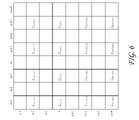
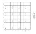
- FIG. 5is a schematic layout of the green image data from the green sensor cells of the image sensor of FIG. 3 .
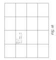
- FIG. 6is a schematic layout of the remaining green image data of FIG. 5 after an optional process of deleting some of the original green image data.
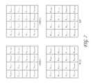
- FIG. 7is a schematic layout of the red, blue, and green image data of FIG. 5 organized for processing in the image processing module of FIG. 1 .
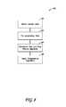
- FIG. 8is a flowchart illustrating an image data transformation technique that can be used with the system illustrated in FIG. 1 .
- FIG. 8Ais a flowchart illustrating a modification of the image data transformation technique of FIG. 8 that can also be used with the system illustrated in FIG. 1 .
- FIG. 9is a schematic layout of blue image data resulting from an image transformation process of FIG. 8 .
- FIG. 10is a schematic layout of red image data resulting from an image transformation process of FIG. 8 .
- FIG. 11illustrates an exemplary optional transform that can be applied to the image data for gamma correction.
- FIG. 12is a flowchart of a control routine that can be used with the system of FIG. 1 to decompress and demosaic image data.
- FIG. 12Ais a flowchart illustrating a modification of the control routine of FIG. 12 that can also be used with the system illustrated in FIG. 1 .
- FIG. 13is a schematic layout of green image data having been decompressed and demosaiced according to the flowchart of FIG. 12 .
- FIG. 14is a schematic layout of half of the original green image data from FIG. 13 , having been decompressed and demosaiced according to the flowchart of FIG. 12 .
- FIG. 15is a schematic layout of blue image data having been decompressed according to the flowchart of FIG. 12 .
- FIG. 16is a schematic layout of blue image data of FIG. 15 having been demosaiced according to the flowchart of FIG. 12 .
- FIG. 1is a schematic diagram of a camera having image sensing, processing, and compression modules, described in the context of a video camera for moving pictures.
- the embodiments disclosed hereinare described in the context of a video camera having a single sensor device with a Bayer pattern filter because these embodiments have particular utility in this context.
- the embodiments and inventions hereincan also be applied to cameras having other types of image sensors (e.g., CMY Bayer as well as other non-Bayer patterns), other numbers of image sensors, operating on different image format types, and being configured for still and/or moving pictures.
- CMY Bayeras well as other non-Bayer patterns
- other numbers of image sensorsoperating on different image format types, and being configured for still and/or moving pictures.
- the embodiments disclosed hereinare exemplary but nonlimiting embodiments, and thus, the inventions disclosed herein are not limited to the disclosed exemplary embodiments.
- a camera 10can include a body or housing 12 configured to support a system 14 configured to detect, process, and optionally store and/or replay video image data.
- the system 14can include optics hardware 16 , an image sensor 18 , an image processing module 20 , a compression module 22 , and a storage device 24 .
- the camera 10can also include a monitor module 26 , a playback module 28 , and a display 30 .
- FIG. 2illustrates a nonlimiting exemplary embodiment of the camera 10 .
- the optics hardware 16can be supported by the housing 12 in a manner that leaves it exposed at its outer surface.
- the system 14is supported within the housing 12 .
- the image sensor 18 , image processing module 20 , and the compression module 22can be housed within the housing 12 .
- the storage device 24can be mounted in the housing 12 . Additionally, in some embodiments, the storage device 24 can be mounted to an exterior of the housing 12 and connected to the remaining portions of the system 14 through any type of known connector or cable. Additionally, the storage device 24 can be connected to the housing 12 with a flexible cable, thus allowing the storage device 24 to be moved somewhat independently from the housing 12 .
- the storage device 24can be worn on a belt of a user, allowing the total weight of the housing 12 to be reduced.
- the housingcan include one or more storage devices 24 inside and mounted to its exterior.
- the housing 12can also support the monitor module 26 , and playbook module 28 .
- the display 30can be configured to be mounted to an exterior of the housing 12 .
- the optics hardware 16can be in the form of a lens system having at least one lens configured to focus an incoming image onto the image sensor 18 .
- the optics hardware 16optionally, can be in the form of a multi-lens system providing variable zoom, aperture, and focus.
- the optics hardware 16can be in the form of a lens socket supported by the housing 12 and configured to receive a plurality of different types of lens systems for example, but without limitation, the optics hardware 16 include a socket configured to receive various sizes of lens systems including a 50-100 millimeter (F2.8) zoom lens, an 18-50 millimeter (F2.8) zoom lens, a 300 millimeter (F2.8) lens, 15 millimeter (F2.8) lens, 25 millimeter (F1.9) lens, 35 millimeter (F1.9) lens, 50 millimeter (F1.9) lens, 85 millimeter (F1.9) lens, and/or any other lens. As noted above, the optics hardware 16 can be configured such that despite which lens is attached thereto, images can be focused upon a light-sensitive surface of the image sensor 18 .
- the image sensor 18can be any type of video sensing device, including, for example, but without limitation, CCD, CMOS, vertically-stacked CMOS devices such as the Foveon® sensor, or a multi-sensor array using a prism to divide light between the sensors.
- the image sensor 18can include a CMOS device having about 12 million photocells. However, other size sensors can also be used.
- camera 10can be configured to output video at “2 k” (e.g., 2048 ⁇ 1152 pixels), “4 k” (e.g., 4,096 ⁇ 2,540 pixels), “4.5 k” horizontal resolution or greater resolutions.
- the “x” quantityrefers to the approximate horizontal resolution.
- “4 k” resolutioncorresponds to about 4000 or more horizontal pixels and “2 k” corresponds to about 2000 or more pixels.
- the sensorcan be as small as about 0.5 inches (8 mm), but it can be about 1.0 inches, or larger.
- the image sensor 18can be configured to provide variable resolution by selectively outputting only a predetermined portion of the sensor 18 .
- the sensor 18 and/or the image processing modulecan be configured to allow a user to identify the resolution of the image data output.
- the camera 10can also be configured to downsample and subsequently process the output of the sensor 18 to yield video output at 2K, 1080 p, 720 p, or any other resolution.
- the image data from the sensor 18can be “windowed”, thereby reducing the size of the output image and allowing for higher readout speeds.
- other size sensorscan also be used.
- the camera 10can be configured to upsample the output of the sensor 18 to yield video output at higher resolutions.
- the sensor 18can include a Bayer pattern filter.
- the sensor 18by way of its chipset (not shown) outputs data representing magnitudes of red, green, or blue light detected by individual photocells of the image sensor 18 .
- FIG. 3schematically illustrates the Bayer pattern output of the sensor 18 .
- the Bayer pattern filterhas twice as many green elements as the number of red elements and the number of blue elements.
- the chipset of the image sensor 18can be used to read the charge on each element of the image sensor and thus output a stream of values in the well-known RGB format output.
- the image processing module 20optionally can be configured to format the data stream from the image sensor 18 in any known manner.
- the image processing module 20can be configured to separate the green, red, and blue image data into three or four separate data compilations.
- the image processing module 20can be configured to separate the red data into one data element, the blue data into one blue data element, and the green data into one green data element.
- the image processing module 20can include a red data processing module 32 , a blue data image processing module 34 , and a first green image data processing module 36 .
- FIG. 3illustrates a data component with the blue and red data removed, leaving only the original green image data.
- the camera 10can be configured to delete or omit some of the green image data.
- the image processing module 20can be configured to delete 1 ⁇ 2 of the green image data so that the total amount of green image data is the same as the amounts of blue and red image data.
- FIG. 6illustrates the remaining data after the image processing module 20 deletes 1 ⁇ 2 of the green image data.
- the rows n ⁇ 3, n ⁇ 1, n+1, and n+3have been deleted. This is merely one example of the pattern of green image data that can be deleted. Other patterns and other amounts of green image data can also be deleted.
- the camera 10can be configured to delete 1 ⁇ 2 of the green image data after the red and blue image data has been transformed based on the green image data. This optional technique is described below following the description of the subtraction of green image data values from the other color image data.
- the image processing module 20can be configured to selectively delete green image data.
- the image processing module 20can include a deletion analysis module (not shown) configured to selectively determine which green image data to delete.
- a deletion modulecan be configured to determine if deleting a pattern of rows from the green image data would result in aliasing artifacts, such as Moiré lines, or other visually perceptible artifacts.
- the deletion modulecan be further configured to choose a pattern of green image data to delete that would present less risk of creating such artifacts.
- the deletion modulecan be configured to choose a green image data deletion pattern of alternating vertical columns if it determines that the image captured by the image sensor 18 includes an image feature characterized by a plurality of parallel horizontal lines. This deletion pattern can reduce or eliminate artifacts, such as Moiré lines, that might have resulted from a deletion pattern of alternating lines of image data parallel to the horizontal lines detected in the image.
- the deletion modulecan also be configured to detect other image features and to use other image data deletion patterns, such as for example, but without limitation, deletion of alternating rows, alternating diagonal lines, or other patterns. Additionally, the deletion module can be configured to delete portions of the other image data, such as the red and blue image data, or other image data depending on the type of sensor used.
- the camera 10can be configured to insert a data field into the image data indicating what image data has been deleted.
- the camera 10can be configured to insert a data field into the beginning of any video clip stored into the storage device 24 , indicating what data has been deleted in each of the “frames” of the video clip.
- the cameracan be configured to insert a data field into each frame captured by the sensor 18 , indicating what image data has been deleted.
- the data fieldcan be as small as a single bit data field, indicating whether or not image data has been deleted. Since the image processing module 20 is configured to delete data in only one pattern, a single bit is sufficient to indicate what data has been deleted.
- the image processing module 20can be configured to selectively delete image data in more than one pattern.
- the image data deletion fieldcan be larger, including a sufficient number of values to provide an indication of which of the plurality of different image data deletion patterns was used.
- This data fieldcan be used by downstream components and or processes to determine to which special positions the remaining image data corresponds.
- the image processing modulecan be configured to retain all of the raw green image data, e.g., the data shown in FIG. 5 .
- the image processing modulecan include one or more green image data processing modules.
- the image processing module 20can include a second green data image processing module 38 .
- the first green data image processing module 36can process half of the green elements and the second green image data processing module 38 can process the remaining green elements.
- the present inventionscan be used in conjunction with other types of patterns, such as for example, but without limitation, CMY and RGBW.
- FIG. 7includes schematic illustrations of the red, blue and two green data components processed by modules 32 , 34 , 36 , and 38 ( FIG. 4 ). This can provide further advantages because the size and configuration of each of these modules can be about the same since they are handling about the same amount of data. Additionally, the image processing module 20 can be selectively switched between modes in which is processes all of the green image data (by using both modules 36 and 38 ) and modes where 1 ⁇ 2 of the green image data is deleted (in which it utilizes only one of modules 36 and 38 ). However, other configurations can also be used.
- the image processing module 20can include other modules and/or can be configured to perform other processes, such as, for example, but without limitation, gamma correction processes, noise filtering processes, etc.
- the image processing module 20can be configured to subtract a value of a green element from a value of a blue element and/or red element.
- the corresponding red or blue elementcan be reduced to zero.
- the magnitude of the green, red, and bluewould be about equal.
- the green valueis subtracted from the red and blue values, the red and blue values will drop to zero or near zero.
- Such a techniquecan help achieve a higher effective compression ratio and yet remain visually lossless due to its relationship to the entropy of the original image data.
- the entropy of an imageis related to the amount of randomness in the image.
- the subtraction of image data of one color, for example, from image data of the other colorscan reduce the randomness, and thus reduce the entropy of the image data of those colors, thereby allowing the data to be compressed at higher compression ratios with less loss.
- an imageis not a collection of random color values. Rather, there is often a certain degree of correlation between surrounding picture elements. Thus, such a subtraction technique can use the correlation of picture elements to achieve better compression.
- the amount of compressionwill depend, at least in part, on the entropy of the original information in the image.
- the magnitudes subtracted from a red or blue pixelcan be the magnitude of the value output from a green pixel adjacent to the subject red or blue pixel. Further, in some embodiments, the green magnitude subtracted from the red or blue elements can be derived from an average of the surrounding green elements. Such techniques are described in greater detail below. However, other techniques can also be used.
- the image processing module 20can also be configured to selectively subtract green image data from the other colors.
- the image processing module 20can be configured to determine if subtracting green image data from a portion of the image data of either of the other colors would provide better compressibility or not.
- the image processing module 20can be configured to insert flags into the image data indicating what portions of the image data has been modified (by e.g., green image data subtraction) and which portions have not been so modified. With such flags, a downstream demosaicing/reconstruction component can selectively add green image values back into the image data of the other colors, based on the status of such data flags.
- image processing module 20can also include a further data reduction module (not shown) configured to round values of the red and blue data. For example, if, after the subtraction of green magnitudes, the red or blue data is near zero (e.g., within one or two on an 8-bit scale ranging from 0-255 or higher magnitudes for a higher resolution system).
- the sensor 18can be a 12-bit sensor outputting red, blue, and green data on a scale of 0-4095. Any rounding or filtering of the data performed the rounding module can be adjusted to achieve the desired effect. For example, rounding can be performed to a lesser extent if it is desired to have lossless output and to a greater extent if some loss or lossy output is acceptable.
- red or blue data having absolute value of up to 2 or 3can be rounded to 0 and still provide a visually lossless output.
- red or blue data having an absolute value of up to 10 to 20can be rounded to 0 and still provide visually lossless output.
- the magnitudes of values that can be rounded to zero, or rounded to other values, and still provide a visually lossless outputdepends on the configuration of the system, including the optics hardware 16 , the image sensor 18 , the resolution of the image sensor, the color resolution (bit) of the image sensor 18 , the types of filtering, anti-aliasing techniques or other techniques performed by the image processing module 20 , the compression techniques performed by the compression module 22 , and/or other parameters or characteristics of the camera 10 .
- the camera 10can be configured to delete 1 ⁇ 2 of the green image data after the red and blue image data has been transformed based on the green image data.
- the processor module 20can be configured to delete 1 ⁇ 2 of the green image data after the average of the magnitudes of the surrounding green data values have been subtracted from the red and blue data values. This reduction in the green data can reduce throughput requirements on the associated hardware. Additionally, the remaining green image data can be used to reconstruct the red and blue image data, described in greater detail below with reference to FIGS. 14 and 16 .
- the camera 10can also include a compression module 22 .
- the compression module 22can be in the form of a separate chip or it can be implemented with software and another processor.
- the compression module 22can be in the form of a commercially available compression chip that performs a compression technique in accordance with the JPEG 2000 standard, or other compression techniques.
- the compression modulecan be configured to perform any type of compression process on the data from the image processing module 20 .
- the compression module 22performs a compression technique that takes advantage of the techniques performed by the image processing module 20 .
- the image processing module 20can be configured to reduce the magnitude of the values of the red and blue data by subtracting the magnitudes of green image data, thereby resulting in a greater number of zero values, as well as other effects.
- the image processing module 20can perform a manipulation of raw data that uses the entropy of the image data.
- the compression technique performed by the compression module 22can be of a type that benefits from the presence of larger strings of zeros to reduce the size of the compressed data output therefrom.
- the compression module 22can be configured to compress the image data from the image processing module 20 to result in a visually lossless output.
- the compression modulecan be configured to apply any known compression technique, such as, but without limitation, JPEG 2000, MotionJPEG, any DCT based codec, any codec designed for compressing RGB image data, H.264, MPEG4, Huffman, or other techniques.
- the various parameters of the compression techniquecan be set to provide a visually lossless output.
- many of the compression techniques noted abovecan be adjusted to different compression rates, wherein when decompressed, the resulting image is better quality for lower compression rates and lower quality for higher compression rates.
- the compression modulecan be configured to compress the image data in a way that provides a visually lossless output, or can be configured to allow a user to adjust various parameters to obtain a visually lossless output.
- the compression module 22can be configured to compress the image data at a compression ratio of about 6:1, 7:1, 8:1 or greater. In some embodiments, the compression module 22 can be configured to compress the image data to a ratio of 12:1 or higher.
- the compression module 22can be configured to allow a user to adjust the compression ratio achieved by the compression module 22 .
- the camera 10can include a user interface that allows a user to input commands that cause the compression module 22 to change the compression ratio.
- the camera 10can provide for variable compression.
- the term “visually lossless”is intended to include output that, when compared side by side with original (never compressed) image data on the same display device, one of ordinary skill in the art would not be able to determine which image is the original with a reasonable degree of accuracy, based only on a visual inspection of the images.
- the camera 10can also include a storage device 24 .
- the storage devicecan be in the form of any type of digital storage, such as, for example, but without limitation, hard disks, flash memory, or any other type of memory device.
- the size of the storage device 24can be sufficiently large to store image data from the compression module 22 corresponding to at least about 30 minutes of video at 12 mega pixel resolution, 12-bit color resolution, and at 60 frames per second.
- the storage device 24can have any size.
- the storage device 24can be mounted on an exterior of the housing 12 . Further, in some embodiments, the storage device 24 can be connected to the other components of the system 14 through standard communication ports, including, for example, but without limitation, IEEE 1394, USB 2.0, IDE, SATA, etc. Further, in some embodiments, the storage device 24 can comprise a plurality of hard drives operating under a RAID protocol. However, any type of storage device can be used.
- the systemcan include a monitor module 26 and a display device 30 configured to allow a user to view video images captured by the image sensor 18 during operation.
- the image processing module 20can include a subsampling system configured to output reduced resolution image data to the monitor module 26 .
- a subsampling systemcan be configured to output video image data to support 2K, 1080 p, 720 p, or any other resolution.
- filters used for demosaicingcan be adapted to also perform downsampling filtering, such that downsampling and filtering can be performed at the same time.
- the monitor module 26can be configured to perform any type of demosaicing process to the data from the image processing module 20 . Thereafter, the monitor module 26 can output a demosaiced image data to the display 30 .
- the display 30can be any type of monitoring device.
- the display 30can be a four-inch LCD panel supported by the housing 12 .
- the display 30can be connected to an infinitely adjustable mount configured to allow the display 30 to be adjusted to any position relative to the housing 12 so that a user can view the display 30 at any angle relative to the housing 12 .
- the display 30can be connected to the monitor module through any type of video cables such as, for example, an RGB or YCC format video cable.
- the playback module 28can be configured to receive data from the storage device 24 , decompressed and demosaic the image data and then output the image data to the display 30 .
- the monitor module 26 and the playback module 28can be connected to the display through an intermediary display controller (not shown).
- the display 30can be connected with a single connector to the display controller.
- the display controllercan be configured to transfer data from either the monitor module 26 or the playback module 28 to the display 30 .
- FIG. 8includes a flowchart 50 illustrating the processing of image data by the camera 10 .
- the flowchart 50can represent a control routine stored in a memory device, such as the storage device 24 , or another storage device (not shown) within the camera 10 .
- a central processing unit (CPU)(not shown) can be configured to execute the control routine.
- CPUcentral processing unit
- the below description of the methods corresponding to the flow chart 50are described in the context of the processing of a single frame of video image data.
- the techniquescan be applied to the processing of a single still image.
- These processescan also be applied to the processing of continuous video, e.g., frame rates of greater than 12, as well as frame rates of 20, 23.976, 24, 30, 60, and 120, or other frame rates between these frame rates or greater.
- control routinecan begin at operation block 52 .
- the camera 10can obtain sensor data.
- the image sensor 18which can include a Bayer Sensor and chipset, can output image data.
- the image sensorcan comprise a CMOS device having a Bayer pattern filter on its light receiving surface.
- the focused image from the optics hardware 16is focused on the Bayer pattern filter on the CMOS device of the image sensor 18 .
- FIG. 3illustrates an example of the Bayer pattern created by the arrangement of Bayer pattern filter on the CMOS device.
- column mis the fourth column from the left edge of the Bayer pattern and row n is the fourth row from the top of the pattern.
- the remaining columns and rowsare labeled relative to column m and row n.
- this layoutis merely chosen arbitrarily for purposes of illustration, and does not limit any of the embodiments or inventions disclosed herein.
- Bayer pattern filtersoften include twice as many green elements as blue and red elements.
- blue elementsonly appear in rows n ⁇ 3, n ⁇ 1, n+1, and n+3.
- Red elementsonly appear in rows n ⁇ 2, n, n+2, and n+4.
- green elementsappear in all rows and columns, interspersed with the red and blue elements.
- the red, blue, and green image data output from the image sensor 18can be received by the image processing module 20 and organized into separate color data components, such as those illustrated in FIG. 7 .
- the image processing module 20can separate the red, blue, and green image data into four separate components.
- FIG. 7illustrates two green components (Green 1 and Green 2 ), a blue component, and a red component.
- Green 1 and Green 2green components
- the image processing module 20optionally, can arbitrarily or selectively delete 1 ⁇ 2 of the green image data.
- the flowchart 50can move on to operation block 54 .
- the image datacan be further processed.
- any one or all of the resulting datae.g., green 1 , green 2 , the blue image data from FIG. 9 , and the red image data from FIG. 10 ) can be further processed.
- the image datacan be pre-emphasized or processed in other ways.
- the image datacan be processed to be more (mathematically) non-linear.
- Some compression algorithmsbenefit from performing such a linearization on the picture elements prior to compression.
- other techniquescan also be used.
- the image datacan be processed with a linear curve, which provides essentially no emphasis.
- this curvecan be used where the image data was, for example but without limitation, floating point data in the normalized 0-1 range.
- log curvescan also be used.
- curves in the form yA*log(B*x+C) where A, B, and C are constants chosen to provide the desired results.
- the above curves and processescan be modified to provide more linear areas in the vicinity of black, similar to those techniques utilized in the well-known Rec709 gamma curve.
- these processescan be applied to all of the image data, or different processes can be applied to the different colors of image data.
- theseare merely exemplary curves that can be used to process the image data, or curves or transforms can also be used.
- these processing techniquescan be applied using mathematical functions such as those noted above, or with Look Up Tables (LUTs).
- LUTsLook Up Tables
- different processes, techniques, or transformscan be used for different types of image data, different ISO settings used during recording of the image data, temperature (which can affect noise levels), etc.
- the flowchart 50can move to an operation block 56 .
- the red and blue picture elementscan be transformed.
- green image datacan be subtracted from each of the blue and red image data components.
- a red or blue image data valuecan be transformed by subtracting a green image data value of at least one of the green picture elements adjacent to the red or blue picture element.
- an average value of the data values of a plurality of adjacent green picture elementscan be subtracted from the red or blue image data value. For example, but without limitation, average values of 2, 3, 4, or more green image data values can be calculated and subtracted from red or blue picture elements in the vicinity of the green picture elements.
- the raw output for the red element R m ⁇ 2,n ⁇ 2is surrounded by four green picture elements G m ⁇ 2,n ⁇ 3 , G m ⁇ 1,n ⁇ 2 , G m ⁇ 3,n ⁇ 2 , and G m ⁇ 2,n ⁇ 1 .
- FIG. 9illustrates a resulting blue data component where the original blue raw data B m ⁇ 1,n ⁇ 1 is transformed, the new value labeled as B′ m ⁇ 1,n ⁇ 1 (only one value in the component is filled in and the same technique can be used for all the blue elements).
- FIG. 10illustrates the red data component having been transformed in which the transformed red element R m ⁇ 2,n ⁇ 2 is identified as R′ m ⁇ 2,n ⁇ 2 .
- the image datacan still be considered “raw” data.
- the mathematical process performed on the dataare entirely reversible such that all of the original values can be obtained by reversing those processes.
- the flowchart 50can move on to an operation block 58 .
- the resulting datawhich is raw or can be substantially raw, can be further compressed to using any known compression algorithm.
- the compression module 22FIG. 1
- the compressed raw datacan be stored in the storage device 24 ( FIG. 1 ).
- FIG. 8Aillustrates a modification of the flowchart 50 , identified by the reference numeral 50 ′.
- the flowchart 50 ′can optionally omit operation block 54 .
- the flowchart 50 ′can also include an operation block 57 in which a look up table can be applied to the image data.
- a look up tablerepresented by the curve of FIG. 11
- the look-up table of FIG. 11is only used for the green picture elements.
- the look-up tablecan also be used for red and blue picture elements. The same look-up table may be used for the three different colors, or each color may have its own look-up table. Additionally, processes other than that represented by the curve of FIG. 11 can also be applied.
- the image data from the image sensor 18can be compressed by a compression ratio of 6 to 1 or greater and remain visually lossless. Additionally, although the image data has been transformed (e.g., by the subtraction of green image data) all of the raw image data is still available to an end user. For example, by reversing certain of the processes, all or substantially all of the original raw data can be extracted and thus further processed, filtered, and/or demosaiced using any process the user desires.
- the data stored in the storage device 24can be decompressed and demosaiced.
- the camera 10can be configured to perform the method illustrated by flowchart 60 .
- the playback module 28can be configured to perform the method illustrated by flowchart 60 .
- a usercan also transfer the data from the storage device 24 into a separate workstation and apply any or all of the steps and/or operations of the flowchart 60 .
- the flowchart 60can begin with the operation block 62 , in which the data from the storage device 24 is decompressed.
- the decompression of the data in operation block 62can be the reverse of the compression algorithm performed in operational block 58 ( FIG. 8 ).
- the flowchart 60can move on to an operation block 64 .
- a process performed in operation block 56( FIG. 8 ) can be reversed.
- the inverse of the curve of FIG. 11 or the inverse of any of the other functions described above with reference to operation block 56 of FIGS. 8 and 8Acan be applied to the image data.
- the flowchart 60can move on to a step 66 .
- the green picture elementscan be demosaiced.
- all the values from the data components Green 1 and/or Green 2can be stored in the storage device 24 .
- the green image data from the data components Green 1 , Green 2can be arranged according to the original Bayer pattern applied by the image sensor 18 .
- the green datacan then be further demosaiced by any known technique, such as, for example, linear interpolation, bilinear, etc.
- FIG. 13illustrates an exemplary layout of green image data demosaiced from all of the raw green image data.
- the green image elements identified with the letter G xrepresent original raw (decompressed) image data and the elements identified with “DG x ” represent elements that were derived from the original data through the demosaic process. This nomenclature is used with regard to the below descriptions of the demosaicing process for the other colors.
- FIG. 14illustrates an exemplary image data layout for green image data demosaiced from 1 ⁇ 2 of the original green image data.
- the flowchart 60can, after the operation block 66 , move on to an operation block 68 .
- the demosaiced green image datacan be further processed.
- noise reduction techniquescan be applied to the green image data.
- any other image processing techniquesuch as anti-aliasing techniques, can also be applied to the green image data.
- the flowchart 60can move on to an operation block 70 .
- the red and blue image datacan be demosaiced.
- the blue image data of FIG. 9can be rearranged according to the original Bayer pattern ( FIG. 15 ).
- the surrounding elements, as shown in FIG. 16can be demosaiced from the existing blue image data using any known demosaicing technique, including linear interpolation, bilinear, etc.
- demosaicing stepthere will be blue image data for every pixel as shown in FIG. 16 .
- this blue image datawas demosaiced based on the modified blue image data of FIG. 9 , i.e., blue image data values from which green image data values were subtracted.
- the operation block 70can also include a demosaicing process of the red image data.
- the red image data from FIG. 10can be rearranged according to the original Bayer pattern and further demosaiced by any known demosaicing process such as linear interpolation, bilinear, etc.
- the flowchartcan move on to an operation block 72 .
- the demosaiced red and blue image datacan be reconstructed from the demosaiced green image data.
- each of the red and blue image data elementscan be reconstructed by adding in the green value from co-sited green image element (the green image element in the same column “m” and row “n” position).
- the blue image dataincludes a blue element value DB m ⁇ 2,n ⁇ 2 . Because the original Bayer pattern of FIG.
- this blue value DB m ⁇ 2,n ⁇ 2was derived through the demosaicing process noted above, based on, for example, blue values from any one of the elements B m ⁇ 3,n ⁇ 3 , B m ⁇ 1,n ⁇ 3 , B m ⁇ 3,n ⁇ 1 , and B m ⁇ 1,n ⁇ 1 or by any other technique or other blue image elements. As noted above, these values were modified in operation block 54 ( FIG. 8 ) and thus do not correspond to the original blue image data detected by the image sensor 18 . Rather, an average green value had been subtracted from each of these values. Thus, the resulting blue image data DB m ⁇ 2,n ⁇ 2 also represents blue data from which green image data has been subtracted. Thus, in one embodiment, the demosaiced green image data for element DG m ⁇ 2,n ⁇ 2 can be added to the blue image value DB m ⁇ 2,n ⁇ 2 thereby resulting in a reconstructed blue image data value.
- the blue and/or red image datacan first be reconstructed before demosaicing.
- the transformed blue image data B′ m ⁇ 1,n ⁇ 1can be first reconstructed by adding the average value of the surrounding green elements. This would result in obtaining or recalculating the original blue image data B m ⁇ 1,n ⁇ 1 .
- This processcan be performed on all of the blue image data.
- the blue image datacan be further demosaiced by any known demosaicing technique.
- the red image datacan also be processed in the same or similar manners.
- FIG. 12Aillustrates a modification of the flowchart 60 , identified by the reference numeral 60 ′.
- Some of the steps described above with reference to the flowchart 60can be similar or the same as some of the corresponding steps of the flowchart 60 ′ and thus are identified with the same reference numerals.
- the flow chart 60 ′can include the operation block 68 ′ following operation block 62 .
- a noise reduction techniquecan be performed on the image data.
- noise reduction techniquescan be applied to the green image data.
- any other image processing techniquesuch as anti-aliasing techniques, can also be applied to the green image data.
- the flow chartcan move on to operation block 70 ′
- the image datacan be demosaiced.
- the green, red, and blue image datacan be demosaiced in two steps.
- the demosaicing of all three colors of image datais represented in a single step, although the same demosaicing techniques described above can be used for this demosaicing process.
- the flow chartcan move on to operation block 72 , in which the red and blue image data can be reconstructed, and operation block 64 in which an inverse look-up table can be applied.
- the image dataAfter the image data has been decompressed and processed according to either of the flow charts 70 or 70 ′, or any other suitable process, the image data can be further processed as demosaiced image data.
- demosaicing the green image data before reconstructing the red and blue image datacertain further advantages can be achieved.
- the human eyeis more sensitive to green light. Demosaicing and processing the green image data optimize the green image values, to which the human eye is more sensitive. Thus, the subsequent reconstruction of the red and blue image data will be affected by the processing of the green image data.
- Bayer patternshave twice as many green elements as red and blue elements. Thus, in embodiments where all of the green data is retained, there is twice as much image data for the green elements as compared to either the red or blue image data elements.
- the demosaicing techniques, filters, and other image processing techniquesresult in a better demosaiced, sharpened, or otherwise filtered image. Using these demosaiced values to reconstruct and demosaic the red and blue image data transfers the benefits associated with the higher resolution of the original green data to the process, reconstruction, and demosaicing of the red and blue elements. As such, the resulting image is further enhanced.
Landscapes
- Engineering & Computer Science (AREA)
- Multimedia (AREA)
- Signal Processing (AREA)
- Physics & Mathematics (AREA)
- Theoretical Computer Science (AREA)
- General Physics & Mathematics (AREA)
- Spectroscopy & Molecular Physics (AREA)
- Studio Devices (AREA)
- Color Television Image Signal Generators (AREA)
- Compression Or Coding Systems Of Tv Signals (AREA)
- Image Processing (AREA)
- Color Television Systems (AREA)
- Compression Of Band Width Or Redundancy In Fax (AREA)
Abstract
Description
Rm,n=Rm,n−(Gm,n−1+Gm+1,n+Gm,n+1+Gm−1,n)/4 (1)
Bm+1,n+1=Bm+1,n+1−(Gm+1,n+Gm+2,n+1+Gm+1,n+2+Gm,n+1)/4 (2)
Claims (12)
Priority Applications (16)
| Application Number | Priority Date | Filing Date | Title |
|---|---|---|---|
| US12/101,882US8174560B2 (en) | 2007-04-11 | 2008-04-11 | Video camera |
| US12/422,507US8237830B2 (en) | 2007-04-11 | 2009-04-13 | Video camera |
| US12/834,854US7830967B1 (en) | 2007-04-11 | 2010-07-12 | Video camera |
| US13/464,803US8872933B2 (en) | 2007-04-11 | 2012-05-04 | Video camera |
| US13/566,924US8878952B2 (en) | 2007-04-11 | 2012-08-03 | Video camera |
| US13/566,868US8358357B2 (en) | 2007-04-11 | 2012-08-03 | Video camera |
| US14/485,611US9230299B2 (en) | 2007-04-11 | 2014-09-12 | Video camera |
| US14/485,612US9245314B2 (en) | 2007-04-11 | 2014-09-12 | Video camera |
| US14/488,030US9019393B2 (en) | 2007-04-11 | 2014-09-16 | Video processing system and method |
| US14/609,090US9436976B2 (en) | 2007-04-11 | 2015-01-29 | Video camera |
| US14/973,384US9787878B2 (en) | 2007-04-11 | 2015-12-17 | Video camera |
| US15/170,795US9792672B2 (en) | 2007-04-11 | 2016-06-01 | Video capture devices and methods |
| US15/293,193US9596385B2 (en) | 2007-04-11 | 2016-10-13 | Electronic apparatus |
| US15/697,908US20180124290A1 (en) | 2007-04-11 | 2017-09-07 | Video camera |
| US15/702,550US20180130183A1 (en) | 2007-04-11 | 2017-09-12 | Video capture devices and methods |
| US16/264,338US20200005434A1 (en) | 2007-04-11 | 2019-01-31 | Video capture devices and methods |
Applications Claiming Priority (3)
| Application Number | Priority Date | Filing Date | Title |
|---|---|---|---|
| US91119607P | 2007-04-11 | 2007-04-11 | |
| US1740607P | 2007-12-28 | 2007-12-28 | |
| US12/101,882US8174560B2 (en) | 2007-04-11 | 2008-04-11 | Video camera |
Related Child Applications (2)
| Application Number | Title | Priority Date | Filing Date |
|---|---|---|---|
| US12/422,507Continuation-In-PartUS8237830B2 (en) | 2007-04-11 | 2009-04-13 | Video camera |
| US13/464,803ContinuationUS8872933B2 (en) | 2007-04-11 | 2012-05-04 | Video camera |
Publications (2)
| Publication Number | Publication Date |
|---|---|
| US20080291319A1 US20080291319A1 (en) | 2008-11-27 |
| US8174560B2true US8174560B2 (en) | 2012-05-08 |
Family
ID=39864353
Family Applications (8)
| Application Number | Title | Priority Date | Filing Date |
|---|---|---|---|
| US12/101,882Active2030-08-14US8174560B2 (en) | 2007-04-11 | 2008-04-11 | Video camera |
| US13/464,803Expired - Fee RelatedUS8872933B2 (en) | 2007-04-11 | 2012-05-04 | Video camera |
| US13/566,868ActiveUS8358357B2 (en) | 2007-04-11 | 2012-08-03 | Video camera |
| US14/485,611ActiveUS9230299B2 (en) | 2007-04-11 | 2014-09-12 | Video camera |
| US14/485,612ActiveUS9245314B2 (en) | 2007-04-11 | 2014-09-12 | Video camera |
| US14/973,384ActiveUS9787878B2 (en) | 2007-04-11 | 2015-12-17 | Video camera |
| US15/293,193ActiveUS9596385B2 (en) | 2007-04-11 | 2016-10-13 | Electronic apparatus |
| US15/697,908AbandonedUS20180124290A1 (en) | 2007-04-11 | 2017-09-07 | Video camera |
Family Applications After (7)
| Application Number | Title | Priority Date | Filing Date |
|---|---|---|---|
| US13/464,803Expired - Fee RelatedUS8872933B2 (en) | 2007-04-11 | 2012-05-04 | Video camera |
| US13/566,868ActiveUS8358357B2 (en) | 2007-04-11 | 2012-08-03 | Video camera |
| US14/485,611ActiveUS9230299B2 (en) | 2007-04-11 | 2014-09-12 | Video camera |
| US14/485,612ActiveUS9245314B2 (en) | 2007-04-11 | 2014-09-12 | Video camera |
| US14/973,384ActiveUS9787878B2 (en) | 2007-04-11 | 2015-12-17 | Video camera |
| US15/293,193ActiveUS9596385B2 (en) | 2007-04-11 | 2016-10-13 | Electronic apparatus |
| US15/697,908AbandonedUS20180124290A1 (en) | 2007-04-11 | 2017-09-07 | Video camera |
Country Status (14)
| Country | Link |
|---|---|
| US (8) | US8174560B2 (en) |
| EP (3) | EP2145330B1 (en) |
| JP (1) | JP5231529B2 (en) |
| KR (2) | KR101503227B1 (en) |
| CN (2) | CN104702926B (en) |
| AU (1) | AU2008240144A1 (en) |
| BR (1) | BRPI0809662A2 (en) |
| CA (2) | CA2683636C (en) |
| ES (1) | ES2486295T3 (en) |
| MX (1) | MX2009010926A (en) |
| RU (1) | RU2473968C2 (en) |
| SG (1) | SG178805A1 (en) |
| TW (1) | TWI451755B (en) |
| WO (1) | WO2008128112A1 (en) |
Cited By (15)
| Publication number | Priority date | Publication date | Assignee | Title |
|---|---|---|---|---|
| US20100165188A1 (en)* | 2008-12-29 | 2010-07-01 | Red.Com, Inc. | Modular digital camera |
| US20100165138A1 (en)* | 2008-12-29 | 2010-07-01 | Red.Com, Inc. | Modular motion camera |
| US20110221901A1 (en)* | 2010-03-11 | 2011-09-15 | Gm Global Technology Operations, Inc. | Adaptive Scene Rendering and V2X Video/Image Sharing |
| US8358357B2 (en) | 2007-04-11 | 2013-01-22 | Red.Com, Inc. | Video camera |
| US8595756B2 (en) | 2011-07-15 | 2013-11-26 | Voxlibertum S.A. | System and method for selling or licensing image files |
| US8878952B2 (en) | 2007-04-11 | 2014-11-04 | Red.Com, Inc. | Video camera |
| US9521384B2 (en) | 2013-02-14 | 2016-12-13 | Red.Com, Inc. | Green average subtraction in image data |
| EP3142002A1 (en) | 2015-09-09 | 2017-03-15 | Red.Com, Inc. | Motion video output for multiple displays |
| US9681028B2 (en) | 2013-03-15 | 2017-06-13 | Red.Com, Inc. | Digital camera with wireless connectivity |
| US10116776B2 (en) | 2015-12-14 | 2018-10-30 | Red.Com, Llc | Modular digital camera and cellular phone |
| WO2019010233A1 (en) | 2017-07-05 | 2019-01-10 | Red. Com, Llc | Video image data processing in electronic devices |
| US10271031B2 (en) | 2014-04-04 | 2019-04-23 | Red.Com, Llc | Broadcast module for a digital camera |
| US10531098B2 (en) | 2015-04-10 | 2020-01-07 | Red.Com, Llc | Video camera with rate control video compression |
| US11323654B2 (en) | 2017-07-21 | 2022-05-03 | Samsung Electronics Co., Ltd | Electronic device and method capable of compressing image on basis of attributes of image data |
| US12333673B2 (en) | 2019-10-30 | 2025-06-17 | intoPIX SA | Image processor |
Families Citing this family (16)
| Publication number | Priority date | Publication date | Assignee | Title |
|---|---|---|---|---|
| USD610186S1 (en)* | 2008-04-03 | 2010-02-16 | Red.Com, Inc. | Video camera |
| JP5695080B2 (en) | 2009-12-16 | 2015-04-01 | レッド.コム,インコーポレイテッド | Resolution-based format for compressed image data |
| TWI392345B (en)* | 2009-12-31 | 2013-04-01 | Chicony Electronics Co Ltd | Portable wi-fi digital video camcorder and system with portable wi-fi digital video camcorder |
| DE102010010736A1 (en) | 2010-03-09 | 2011-09-15 | Arnold & Richter Cine Technik Gmbh & Co. Betriebs Kg | Method of compressing image data |
| US8644163B2 (en) | 2010-03-25 | 2014-02-04 | Chicony Electronics Co., Ltd. | System with wireless network device and method for processing wireless network profile |
| USD629435S1 (en)* | 2010-06-02 | 2010-12-21 | Wgi Innovations, Ltd. | Action camera |
| WO2013187127A1 (en) | 2012-06-13 | 2013-12-19 | 富士フイルム株式会社 | Image processing system, transmitting side device, and receiving side device |
| CN104717474B (en)* | 2013-12-16 | 2017-07-25 | 瑞昱半导体股份有限公司 | Image processing method and module and electronic equipment comprising same |
| JP6258842B2 (en)* | 2014-12-10 | 2018-01-10 | 株式会社Soken | Image processing apparatus and lane boundary line recognition system |
| JP2017099616A (en)* | 2015-12-01 | 2017-06-08 | ソニー株式会社 | Surgical control device, surgical control method and program, and surgical system |
| US10223911B2 (en) | 2016-10-31 | 2019-03-05 | Echelon Corporation | Video data and GIS mapping for traffic monitoring, event detection and change prediction |
| US10438071B2 (en) | 2017-01-25 | 2019-10-08 | Echelon Corporation | Distributed system for mining, correlating, and analyzing locally obtained traffic data including video |
| US10375303B1 (en) | 2017-07-24 | 2019-08-06 | Samuel Raymond Kinney | Ultra-high resolution cinema camera system |
| EP3442235B1 (en)* | 2017-08-10 | 2022-03-16 | Continental Automotive GmbH | Device and method for raw image data compression |
| CN113744138B (en)* | 2020-05-29 | 2025-03-07 | 北京小米移动软件有限公司 | Image processing method, image processing device and storage medium |
| US11813655B2 (en) | 2021-05-20 | 2023-11-14 | Kuka Systems North America Llc | Apparatus and methods for forming attachment pads |
Citations (109)
| Publication number | Priority date | Publication date | Assignee | Title |
|---|---|---|---|---|
| US3972010A (en) | 1968-01-10 | 1976-07-27 | Ray Milton Dolby | Compressors, expanders and noise reduction systems |
| US4200889A (en) | 1976-12-27 | 1980-04-29 | Basf Aktiengesellschaft | Complementary pre-emphasis and de-emphasis circuits for a video signal transfer channel |
| US4316213A (en) | 1980-09-23 | 1982-02-16 | Rca Corporation | Video processor employing variable amplitude compression of the chrominance component |
| US4561012A (en) | 1983-12-27 | 1985-12-24 | Rca Corporation | Pre-emphasis and de-emphasis filters for a composite NTSC format video signal |
| US5016107A (en) | 1989-05-09 | 1991-05-14 | Eastman Kodak Company | Electronic still camera utilizing image compression and digital storage |
| US5040063A (en) | 1988-04-04 | 1991-08-13 | Zenith Electronics Corporation | TV signal transmission systems and methods |
| US5049983A (en) | 1989-10-19 | 1991-09-17 | Sony Corporation | Digital camera apparatus having an analog emphasis circuitry |
| US5249053A (en) | 1991-02-05 | 1993-09-28 | Dycam Inc. | Filmless digital camera with selective image compression |
| US5255083A (en) | 1991-06-05 | 1993-10-19 | Sony Corporation Of America | Digital color correction system and method |
| US5303062A (en) | 1990-01-16 | 1994-04-12 | Hitachi, Ltd. | Folding camcorder for compact storage |
| US5343243A (en) | 1992-01-07 | 1994-08-30 | Ricoh Company, Ltd. | Digital video camera |
| US5526047A (en) | 1993-09-24 | 1996-06-11 | Asahi Kogaku Kogyo Kabushiki Kaisha | Scheme camera employing compression recording |
| US5535246A (en) | 1991-06-04 | 1996-07-09 | National Transcommunications Limited | Method of video noise reduction using non-linear pre/de-emphasis |
| US5537157A (en) | 1993-04-21 | 1996-07-16 | Kinya Washino | Multi-format audio/video production system |
| US5563655A (en) | 1994-02-28 | 1996-10-08 | Eastman Kodak Company | Intelligent digital image storage for an electronic camera |
| US5592237A (en) | 1994-11-04 | 1997-01-07 | Infimed, Inc. | High resolution image processor with multiple bus architecture |
| US5592224A (en) | 1994-04-14 | 1997-01-07 | Lg Electronics Inc. | Device for rotating liquid crystal display coupled to camcorder |
| WO1997009818A1 (en) | 1995-08-21 | 1997-03-13 | Starcam Systems, Inc. | High-speed high-resolution multi-frame real-time digital camera |
| US5818524A (en) | 1992-10-06 | 1998-10-06 | Nikon Corporation | Digital still camera having an image data compression function |
| US5949468A (en) | 1995-07-17 | 1999-09-07 | Canon Kabushiki Kaisha | Light quantity measuring system and exposure apparatus using the same |
| US5991515A (en) | 1992-11-10 | 1999-11-23 | Adobe Systems Incorporated | Method and apparatus for compressing and decompressing data prior to display |
| US5999220A (en) | 1997-04-07 | 1999-12-07 | Washino; Kinya | Multi-format audio/video production system with frame-rate conversion |
| US6009201A (en) | 1997-06-30 | 1999-12-28 | Intel Corporation | Efficient table-lookup based visually-lossless image compression scheme |
| US6154493A (en)* | 1998-05-21 | 2000-11-28 | Intel Corporation | Compression of color images based on a 2-dimensional discrete wavelet transform yielding a perceptually lossless image |
| US6192086B1 (en) | 1999-01-14 | 2001-02-20 | Antec Corporation | Digital sub-systems and building blocks for a mostly digital low-cost BTSC compatible encoder |
| US6198505B1 (en) | 1999-07-19 | 2001-03-06 | Lockheed Martin Corp. | High resolution, high speed digital camera |
| US6262763B1 (en) | 1999-07-01 | 2001-07-17 | Sony Corporation | Actual size image display |
| US6269217B1 (en) | 1998-05-21 | 2001-07-31 | Eastman Kodak Company | Multi-stage electronic motion image capture and processing system |
| US6275263B1 (en) | 1997-10-06 | 2001-08-14 | Sigma Designs, Inc. | Multi-function USB video capture chip using bufferless data compression |
| USRE37342E1 (en) | 1993-04-21 | 2001-08-28 | Multi-Format, Inc. | Dual format digital video production system |
| US6285794B1 (en) | 1998-04-17 | 2001-09-04 | Adobe Systems Incorporated | Compression and editing of movies by multi-image morphing |
| US6314206B1 (en) | 1997-04-07 | 2001-11-06 | Asahi Kogaku Kogyo Kabushiki Kaisha | Compression ratio setting device |
| US20020041707A1 (en) | 2000-04-07 | 2002-04-11 | Newman David A. | Real-time color correction of digitally recorded video |
| US6466699B2 (en) | 1997-04-30 | 2002-10-15 | Ricoh Company, Ltd | Reversible DCT for lossless—lossy compression |
| US20020196354A1 (en) | 2001-06-19 | 2002-12-26 | Michael Chang | Intelligent blemish control algorithm and apparatus |
| US20030007567A1 (en) | 2001-06-26 | 2003-01-09 | Newman David A. | Method and apparatus for real-time editing of plural content streams |
| US20030011747A1 (en) | 2000-07-12 | 2003-01-16 | Reimar Lenz | Digital, high-resolution motion-picture camera |
| US20030038885A1 (en) | 1998-05-21 | 2003-02-27 | Nestor M. Rodriguez | Wide gamut motion image capture process for post production applications |
| USRE38079E1 (en) | 1993-04-21 | 2003-04-15 | Muti-Format, Inc. | Multi-format audio/video production system |
| US6567988B1 (en) | 1996-09-02 | 2003-05-20 | Sony Corporation | Video signal transmission apparatus and video signal transmission method |
| US6597860B2 (en) | 1997-08-14 | 2003-07-22 | Samsung Electronics | Digital camcorder apparatus with MPEG-2 compatible video compression |
| US20030156188A1 (en) | 2002-01-28 | 2003-08-21 | Abrams Thomas Algie | Stereoscopic video |
| US20030185302A1 (en)* | 2002-04-02 | 2003-10-02 | Abrams Thomas Algie | Camera and/or camera converter |
| US20030202106A1 (en) | 2002-04-24 | 2003-10-30 | Robert Kandleinsberger | Digital camera with overscan sensor |
| US6697106B1 (en) | 1999-03-26 | 2004-02-24 | Fuji Photo Film Co., Ltd. | Apparatus for processing image signals representative of a still picture and moving pictures picked up |
| US20040051793A1 (en) | 2002-09-18 | 2004-03-18 | Tecu Kirk S. | Imaging device |
| US20040095477A1 (en) | 2002-08-09 | 2004-05-20 | Takashi Maki | ROI setting method and apparatus, electronic camera apparatus, program, and recording medium |
| US20040196389A1 (en) | 2003-02-04 | 2004-10-07 | Yoshiaki Honda | Image pickup apparatus and method thereof |
| US20040201701A1 (en) | 2001-09-06 | 2004-10-14 | Shuichi Takagi | Camera with wireless virtual storage |
| US6825876B1 (en) | 1999-06-08 | 2004-11-30 | Lightsurf Technologies, Inc. | Digital camera device with methodology for efficient color conversion |
| US20040246346A1 (en) | 2003-06-03 | 2004-12-09 | Kim Yong-Ho | Photographing apparatus for automatically setting compression format and method thereof |
| US6859226B2 (en) | 1989-03-30 | 2005-02-22 | Canon Kabushiki Kaisha | Camera with first and second compression units and with a digital capture unit providing an output to the first or second compression unit |
| US6867717B1 (en) | 2002-04-04 | 2005-03-15 | Dalsa, Inc. | Digital encoder and method of encoding high dynamic range video images |
| US6937276B2 (en) | 2001-08-22 | 2005-08-30 | Benq Corporation | Digital camera with low memory usage |
| US6958774B2 (en) | 2001-01-19 | 2005-10-25 | Nikon Corporation | Electronic camera capable of storing lossless compressed data based on a threshold value |
| EP1605403A1 (en) | 2004-06-08 | 2005-12-14 | STMicroelectronics S.r.l. | Filtering of noisy images |
| US20050276496A1 (en) | 2004-05-31 | 2005-12-15 | Claus Molgaard | Image compression for rapid high-quality imaging |
| US6983074B1 (en) | 2000-06-14 | 2006-01-03 | Adobe Systems Incorporated | Data compression system and technique |
| US20060007324A1 (en) | 1999-06-04 | 2006-01-12 | Hirofumi Takei | White balance correcting device |
| US20060012694A1 (en) | 2002-12-24 | 2006-01-19 | Yutaka Yoneda | Pixel defect detecting/correcting device and pixel defect detecting/correcting method |
| US6990240B2 (en) | 2000-06-28 | 2006-01-24 | Canon Kabushiki Kaisha | Image processing apparatus |
| US6995794B2 (en) | 1999-06-30 | 2006-02-07 | Logitech Europe S.A. | Video camera with major functions implemented in host software |
| US6995793B1 (en) | 2000-11-14 | 2006-02-07 | Eastman Kodak Company | Video tap for a digital motion camera that simulates the look of post processing |
| US20060061659A1 (en) | 2004-09-17 | 2006-03-23 | Chiyumi Niwa | Image capturing apparatus and control method thereof |
| US7038719B2 (en) | 2001-09-21 | 2006-05-02 | Canon Kabushiki Kaisha | Image sensing apparatus, image processing method, recording medium, and program |
| US7050642B2 (en) | 1994-05-19 | 2006-05-23 | Next Software, Inc. | Method and apparatus for video compression using microwavelets |
| US20060114987A1 (en) | 1998-12-21 | 2006-06-01 | Roman Kendyl A | Handheld video transmission and display |
| US20060165179A1 (en) | 2005-01-27 | 2006-07-27 | Technion Research & Development Foundation Ltd. | Acquisition of image sequences with enhanced resolution |
| US20060170786A1 (en) | 2005-01-31 | 2006-08-03 | Nara Won | Digital camera and method |
| US7095899B2 (en) | 2002-03-27 | 2006-08-22 | Microsoft Corporation | System and method for progressively transforming and coding digital data |
| US20060221199A1 (en) | 2004-09-30 | 2006-10-05 | Seiko Epson Corporation | Digital camera and image processing method |
| US20060221203A1 (en) | 2005-03-31 | 2006-10-05 | Kabushiki Kaisha Toshiba | Camera apparatus |
| US20060221230A1 (en) | 2003-04-17 | 2006-10-05 | Nokia Corporation | Mobile camera telephone |
| US7127116B2 (en) | 1997-09-29 | 2006-10-24 | Intel Corporation | Image data compression |
| US7126634B2 (en) | 2001-07-26 | 2006-10-24 | Matsushita Electric Industrial Co., Ltd. | Image processing system, image pickup apparatus and image processing apparatus |
| US7155066B2 (en) | 2001-05-31 | 2006-12-26 | Agilent Technologies, Inc. | System and method for demosaicing raw data images with compression considerations |
| US7174045B2 (en) | 1997-06-04 | 2007-02-06 | Nikon Corporation | Image compression apparatus, method and recording medium storing an image compression program |
| US20070035636A1 (en) | 2005-08-09 | 2007-02-15 | Sunplus Technology Co., Ltd. | Method and system of eliminating color noises caused by an interpolation |
| US20070041634A1 (en) | 2005-08-17 | 2007-02-22 | Canon Kabushiki Kaisha | Image capturing apparatus, image processing apparatus and image processing method |
| US7212313B1 (en) | 1999-05-25 | 2007-05-01 | Adobe Systems Incorporated | Reducing storage requirements for display data |
| US20070127095A1 (en) | 2005-12-01 | 2007-06-07 | Canon Kabushiki Kaisha | Image capturing apparatus, image processing method, program, and storage medium |
| US20070153093A1 (en) | 2005-12-30 | 2007-07-05 | Mediatek Incorporation | Apparatus and method for image capturing with an image scaling unit to scale a portion of an image |
| US20070216782A1 (en) | 2006-03-20 | 2007-09-20 | Donald Lee Chernoff | Method of processing and storing files in a digital camera |
| US20070285517A1 (en) | 2006-06-13 | 2007-12-13 | Shinichi Ishikuro | Imaging apparatus |
| US7312821B2 (en) | 2003-06-03 | 2007-12-25 | Hewlett-Packard Development Company, L.P. | Time-sliced still image generation |
| US20080002035A1 (en) | 2006-06-30 | 2008-01-03 | Akimitsu Yoshida | Information processing apparatus and image processing parameter editing method, and image sensing apparatus and its control method |
| US20080012953A1 (en)* | 2006-07-13 | 2008-01-17 | Vimicro Corporation | Image Sensors |
| US20080018746A1 (en) | 2006-07-19 | 2008-01-24 | Pentax Corporation | Method and apparatus for recording image data |
| US7324141B2 (en) | 2002-09-11 | 2008-01-29 | Canon Kabushiki Kaisha | Image sensing apparatus and data processing method used therein |
| US20080062272A1 (en) | 1999-09-28 | 2008-03-13 | Nikon Corporation | Electronic camera that reduces processing time by performing different processes in parallel |
| US20080079818A1 (en) | 1993-04-05 | 2008-04-03 | Koji Takahashi | Image processing apparatus |
| US7365658B2 (en) | 2006-02-28 | 2008-04-29 | The Board Of Trustees Of The University Of Arkansas | Method and apparatus for lossless run-length data encoding |
| US7369161B2 (en) | 1999-06-08 | 2008-05-06 | Lightsurf Technologies, Inc. | Digital camera device providing improved methodology for rapidly taking successive pictures |
| US7385647B2 (en) | 2004-03-10 | 2008-06-10 | Samsung Electronics Co., Ltd. | Housing cover for image photographing apparatus |
| US7388992B2 (en) | 2003-06-25 | 2008-06-17 | Nokia Corporation | Digital photographic device for controlling compression parameter of image data and method of deciding compression parameter value of image data |
| US7394485B2 (en) | 2003-05-20 | 2008-07-01 | Samsung Electronics Co., Ltd. | Combination image-capturing apparatus and method for efficiently combining a digital still camera with a digital video camera |
| WO2008128112A1 (en) | 2007-04-11 | 2008-10-23 | Red.Com, Inc. | Video camera |
| US20080301315A1 (en) | 2007-05-30 | 2008-12-04 | Adobe Systems Incorporated | Transmitting Digital Media Streams to Devices |
| US7477781B1 (en) | 2002-10-10 | 2009-01-13 | Dalsa Corporation | Method and apparatus for adaptive pixel correction of multi-color matrix |
| US7483909B2 (en) | 2001-04-10 | 2009-01-27 | Adobe Systems Incorporated | System, method and apparatus for converting and integrating media files |
| US20090052797A1 (en) | 2006-12-15 | 2009-02-26 | Sony Corporation | Imaging device, image processing device, image processing method, program for image processing method, and recording medium having program for image processing method recorded thereon |
| US20090052861A1 (en) | 2007-08-22 | 2009-02-26 | Adobe Systems Incorporated | Systems and Methods for Interactive Video Frame Selection |
| US20090080784A1 (en) | 2007-09-21 | 2009-03-26 | Adobe Systems Incorporated | Enhanced decompression of compressed data |
| US7512283B2 (en) | 2002-12-23 | 2009-03-31 | Eastman Kodak Company | Method of transmitting selected regions of interest of digital video data at selected resolutions |
| US7577689B1 (en) | 2005-06-15 | 2009-08-18 | Adobe Systems Incorporated | Method and system to archive data |
| US7590301B2 (en) | 2005-07-07 | 2009-09-15 | Sunplus Technology Co., Ltd. | Method and system for correcting defective pixels of a color image |
| US20100013963A1 (en) | 2007-04-11 | 2010-01-21 | Red.Com, Inc. | Video camera |
| US7796186B2 (en)* | 2006-07-12 | 2010-09-14 | Sony Corporation | Imaging apparatus |
| US7937919B2 (en) | 2006-06-09 | 2011-05-10 | Deere & Company | Flexible cutting platform with passive float arm stop in an agricultural harvesting machine |
Family Cites Families (118)
| Publication number | Priority date | Publication date | Assignee | Title |
|---|---|---|---|---|
| GB2087194B (en) | 1980-11-07 | 1985-09-11 | Victor Company Of Japan | Video signal recording/reproducing apparatus controllable via camera |
| JPH0654239B2 (en) | 1986-02-20 | 1994-07-20 | 日野自動車工業株式会社 | Vehicle lateral momentum detection device |
| US5043821A (en) | 1988-08-31 | 1991-08-27 | Canon Kabushiki Kaisha | Image pickup device having a frame-size memory |
| US5053861A (en)* | 1989-07-24 | 1991-10-01 | Eastman Kodak Company | Compression method and apparatus for single-sensor color imaging systems |
| US5172227A (en)* | 1990-12-10 | 1992-12-15 | Eastman Kodak Company | Image compression with color interpolation for a single sensor image system |
| JPH0654239A (en) | 1992-07-29 | 1994-02-25 | Canon Inc | Electronic camera |
| US5442718A (en) | 1992-09-07 | 1995-08-15 | Sony Corporation | Apparatus and method for storing and reproducing digital image data yielding high resolution and high quality video image data |
| US5412427A (en) | 1993-10-29 | 1995-05-02 | Eastman Kodak Company | Electronic camera utilizing image compression feedback for improved color processing |
| US6549666B1 (en) | 1994-09-21 | 2003-04-15 | Ricoh Company, Ltd | Reversible embedded wavelet system implementation |
| US5875122A (en) | 1996-12-17 | 1999-02-23 | Intel Corporation | Integrated systolic architecture for decomposition and reconstruction of signals using wavelet transforms |
| US6351282B1 (en)* | 1997-09-02 | 2002-02-26 | Intel Corporation | Method and apparatus for taking digital pictures with an industry standard film camera |
| AU8073298A (en) | 1997-09-11 | 1999-03-29 | Intel Corporation | A method for directly compressing a color image and tailoring the compression based on the color filter array, optics, and sensor characteristics |
| US6130960A (en) | 1997-11-03 | 2000-10-10 | Intel Corporation | Block-matching algorithm for color interpolation |
| US6091851A (en) | 1997-11-03 | 2000-07-18 | Intel Corporation | Efficient algorithm for color recovery from 8-bit to 24-bit color pixels |
| US6169317B1 (en) | 1998-02-13 | 2001-01-02 | Canon Kabushiki Kaisha | Photoelectric conversion device and image sensor |
| US7253836B1 (en) | 1998-06-30 | 2007-08-07 | Nikon Corporation | Digital camera, storage medium for image signal processing, carrier wave and electronic camera |
| JP4182566B2 (en)* | 1998-08-24 | 2008-11-19 | 株式会社ニコン | Digital camera and computer-readable recording medium |
| US6124811A (en) | 1998-07-02 | 2000-09-26 | Intel Corporation | Real time algorithms and architectures for coding images compressed by DWT-based techniques |
| JP2000244936A (en) | 1999-02-10 | 2000-09-08 | Texas Instr Inc <Ti> | Operation method of digital still camera |
| US6878977B1 (en) | 1999-02-25 | 2005-04-12 | Canon Kabushiki Kaisha | Photoelectric conversion device, and image sensor and image input system making use of the same |
| US6778709B1 (en) | 1999-03-12 | 2004-08-17 | Hewlett-Packard Development Company, L.P. | Embedded block coding with optimized truncation |
| JP2000285229A (en) | 1999-03-15 | 2000-10-13 | Texas Instr Inc <Ti> | Defective pixel filtering for digital imager |
| FR2792432B1 (en) | 1999-04-15 | 2001-07-13 | Canon Kk | DEVICE AND METHOD FOR DIGITAL SIGNAL TRANSFORMATION |
| US8212893B2 (en) | 1999-06-08 | 2012-07-03 | Verisign, Inc. | Digital camera device and methodology for distributed processing and wireless transmission of digital images |
| DE60040786D1 (en) | 1999-08-05 | 2008-12-24 | Sanyo Electric Co | image interpolation |
| US6798901B1 (en) | 1999-10-01 | 2004-09-28 | Intel Corporation | Method of compressing a color image |
| US6933970B2 (en) | 1999-12-20 | 2005-08-23 | Texas Instruments Incorporated | Digital still camera system and method |
| US7218348B2 (en) | 2000-06-02 | 2007-05-15 | Fujifilm Corporation | Solid-state electronic imaging device and method of controlling opertion thereof |
| JP2002051266A (en) | 2000-08-02 | 2002-02-15 | Sony Corp | Automatic pixel defect detecting and correcting device for image pickup element and image pickup device using the same |
| JP4055927B2 (en) | 2000-08-25 | 2008-03-05 | シャープ株式会社 | Image processing apparatus and digital camera |
| JP3727012B2 (en)* | 2000-11-28 | 2005-12-14 | シャープ株式会社 | Color solid-state imaging device |
| US7092016B2 (en) | 2001-02-09 | 2006-08-15 | Eastman Kodak Company | Method and system for motion image digital processing |
| US20020167602A1 (en) | 2001-03-20 | 2002-11-14 | Truong-Thao Nguyen | System and method for asymmetrically demosaicing raw data images using color discontinuity equalization |
| FR2826823B1 (en) | 2001-06-27 | 2003-10-10 | Canon Kk | METHOD AND DEVICE FOR PROCESSING A CODE DIGITAL SIGNAL |
| US20030112863A1 (en) | 2001-07-12 | 2003-06-19 | Demos Gary A. | Method and system for improving compressed image chroma information |
| JP4267848B2 (en) | 2001-09-25 | 2009-05-27 | 株式会社リコー | Image encoding device, image decoding device, image encoding method, and image decoding method |
| EP1308888A1 (en) | 2001-11-06 | 2003-05-07 | STMicroelectronics S.r.l. | A method of processing digital images |
| WO2003053781A1 (en) | 2001-12-06 | 2003-07-03 | Goodrich Corporation | Aircraft deicing system |
| JP3922919B2 (en) | 2001-12-11 | 2007-05-30 | 株式会社リコー | Still image expansion apparatus and still image expansion method |
| US6956976B2 (en) | 2002-01-04 | 2005-10-18 | Warner Bros. Enterianment Inc. | Reduction of differential resolution of separations |
| JP3788393B2 (en)* | 2002-06-10 | 2006-06-21 | ソニー株式会社 | Digital still camera device, video camera device and information terminal device |
| JP2004038693A (en)* | 2002-07-04 | 2004-02-05 | Canon Inc | Data conversion method and image processing device |
| US7330596B2 (en) | 2002-07-17 | 2008-02-12 | Ricoh Company, Ltd. | Image decoding technique for suppressing tile boundary distortion |
| US7015961B2 (en) | 2002-08-16 | 2006-03-21 | Ramakrishna Kakarala | Digital image system and method for combining demosaicing and bad pixel correction |
| US7376183B2 (en) | 2002-09-09 | 2008-05-20 | Warner Bros. Entertainment, Inc. | Post-production processing |
| US7116716B2 (en) | 2002-11-01 | 2006-10-03 | Microsoft Corporation | Systems and methods for generating a motion attention model |
| JP2004221836A (en) | 2003-01-14 | 2004-08-05 | Ricoh Co Ltd | Image processing apparatus, program, storage medium, and code decompression method |
| JP3970185B2 (en) | 2003-01-14 | 2007-09-05 | 富士フイルム株式会社 | Solid-state image sensor and digital camera |
| JP2004248061A (en)* | 2003-02-14 | 2004-09-02 | Fuji Photo Film Co Ltd | Image processing apparatus, method, and program |
| JP2004248152A (en) | 2003-02-17 | 2004-09-02 | Ricoh Co Ltd | Image compression device, image decompression device, image compression method, image decompression method, program, and recording medium |
| US7257278B2 (en)* | 2003-02-26 | 2007-08-14 | Hewlett-Packard Development Company, L.P. | Image sensor for capturing and filtering image data |
| US6944333B2 (en)* | 2003-04-30 | 2005-09-13 | Ventana Medical Systems, Inc. | Color image compression via spectral decorrelation and elimination of spatial redundancy |
| JP2004349842A (en)* | 2003-05-20 | 2004-12-09 | Fuji Photo Film Co Ltd | Method and program for correcting composite image |
| JP4610930B2 (en) | 2003-06-05 | 2011-01-12 | オリンパス株式会社 | Image processing apparatus and image processing program |
| JP2005210216A (en)* | 2004-01-20 | 2005-08-04 | Konica Minolta Photo Imaging Inc | Image pickup device and method of processing noise in motion image |
| US8832434B2 (en) | 2004-02-13 | 2014-09-09 | Hewlett-Packard Development Company, L.P. | Methods for generating data for describing scalable media |
| US7504968B2 (en) | 2004-02-13 | 2009-03-17 | Hewlett-Packard Development Company, L.P. | Media data decoding device |
| US6989773B2 (en) | 2004-02-13 | 2006-01-24 | Hewlett-Packard Development Company, L.P. | Media data encoding device |
| US7970231B2 (en) | 2004-02-19 | 2011-06-28 | Mitsubishi Denki Kabushiki Kaisha | Image processing method |
| JP4451181B2 (en) | 2004-03-26 | 2010-04-14 | オリンパス株式会社 | Image compression method and image compression apparatus |
| JP2004282780A (en)* | 2004-05-10 | 2004-10-07 | Canon Inc | Imaging device |
| RU2248307C1 (en)* | 2004-05-17 | 2005-03-20 | Общество с ограниченной ответственностью "Альтоника" | Ground situation observation system |
| JP2005354278A (en) | 2004-06-09 | 2005-12-22 | Seiko Epson Corp | Image data processing for processing image data of an image captured by an imaging means |
| US7546665B2 (en)* | 2004-07-30 | 2009-06-16 | Doyle's Deer Gear | Cinch for tether |
| US20060061822A1 (en)* | 2004-09-22 | 2006-03-23 | Sung Chih-Ta S | Method and device for temporarily storing image data |
| US8477173B2 (en) | 2004-10-15 | 2013-07-02 | Lifesize Communications, Inc. | High definition videoconferencing system |
| US7480417B2 (en) | 2004-10-19 | 2009-01-20 | Microsoft Corp. | System and method for encoding mosaiced image data employing a reversible color transform |
| JP4118272B2 (en)* | 2004-12-17 | 2008-07-16 | 三洋電機株式会社 | Image processing device |
| US8072643B2 (en) | 2004-12-17 | 2011-12-06 | Sanyo Electric Co., Ltd. | Image processing apparatus |
| US7936919B2 (en) | 2005-01-18 | 2011-05-03 | Fujifilm Corporation | Correction of color balance of face images depending upon whether image is color or monochrome |
| US7110605B2 (en)* | 2005-02-04 | 2006-09-19 | Dts Az Research, Llc | Digital intermediate (DI) processing and distribution with scalable compression in the post-production of motion pictures |
| DE102005063503B4 (en)* | 2005-03-10 | 2011-05-19 | Inaba, Minoru, Oyama | 3D display and 3D projector |
| JP2006311314A (en)* | 2005-04-28 | 2006-11-09 | Matsushita Electric Ind Co Ltd | Color separation processing method and color separation processing circuit |
| US7956871B2 (en) | 2005-04-28 | 2011-06-07 | Samsung Electronics Co., Ltd. | Color disparity correction in image sensors methods and circuits |
| JP4769039B2 (en) | 2005-07-26 | 2011-09-07 | パナソニック株式会社 | Digital signal encoding and decoding apparatus and method |
| US7511323B2 (en) | 2005-08-11 | 2009-03-31 | Aptina Imaging Corporation | Pixel cells in a honeycomb arrangement |
| GB2429593A (en) | 2005-08-26 | 2007-02-28 | Electrosonic Ltd | Data compressing using a wavelet compression scheme |
| JP4716949B2 (en) | 2005-09-02 | 2011-07-06 | 株式会社リコー | Image processing apparatus and image processing method |
| JP4682102B2 (en) | 2005-09-02 | 2011-05-11 | キヤノン株式会社 | Image coding apparatus and image coding method |
| JP4616135B2 (en) | 2005-09-21 | 2011-01-19 | オリンパス株式会社 | Imaging apparatus and image recording apparatus |
| JP4688165B2 (en) | 2005-09-30 | 2011-05-25 | 株式会社リコー | Image processing apparatus and image processing method |
| JP4940639B2 (en) | 2005-09-30 | 2012-05-30 | セイコーエプソン株式会社 | Image processing apparatus, image processing method, and image processing program |
| US20070092149A1 (en) | 2005-10-24 | 2007-04-26 | Sung Chih-Ta S | Method and apparatus of high quality video compression |
| US8571346B2 (en) | 2005-10-26 | 2013-10-29 | Nvidia Corporation | Methods and devices for defective pixel detection |
| US20070133902A1 (en) | 2005-12-13 | 2007-06-14 | Portalplayer, Inc. | Method and circuit for integrated de-mosaicing and downscaling preferably with edge adaptive interpolation and color correlation to reduce aliasing artifacts |
| US8005297B2 (en) | 2006-01-18 | 2011-08-23 | Qualcomm Incorporated | Method and apparatus for adaptive and self-calibrated sensor green channel gain balancing |
| US7796836B2 (en) | 2006-03-03 | 2010-09-14 | General Atomics | Color condensation for image transformation and/or compression |
| US8014597B1 (en) | 2006-03-22 | 2011-09-06 | Woodman Labs | Method for efficient compression and decoding of single sensor color image data |
| JP2007267072A (en) | 2006-03-29 | 2007-10-11 | Sanyo Electric Co Ltd | Electronic camera |
| US7868879B2 (en)* | 2006-05-12 | 2011-01-11 | Doremi Labs, Inc. | Method and apparatus for serving audiovisual content |
| US8687087B2 (en) | 2006-08-29 | 2014-04-01 | Csr Technology Inc. | Digital camera with selectively increased dynamic range by control of parameters during image acquisition |
| TWI324011B (en) | 2006-09-12 | 2010-04-21 | Nuvoton Technology Corp | Method for compensating pixel of image |
| DE502006008720D1 (en)* | 2006-09-28 | 2011-02-24 | Abb Technology Ag | Method for determining a switch-on threshold and electronic circuit arrangement for carrying out the method |
| JP4265642B2 (en) | 2006-10-16 | 2009-05-20 | ソニー株式会社 | Information processing apparatus and method, recording medium, and program |
| JP4680166B2 (en) | 2006-10-30 | 2011-05-11 | ソニー株式会社 | Imaging apparatus and imaging method |
| JP4859632B2 (en) | 2006-11-15 | 2012-01-25 | 富士通セミコンダクター株式会社 | Image processing apparatus and image processing method |
| US7907791B2 (en) | 2006-11-27 | 2011-03-15 | Tessera International, Inc. | Processing of mosaic images |
| WO2008128205A1 (en) | 2007-04-13 | 2008-10-23 | Presler Ari M | Digital cinema camera system for recording, editing and visualizing images |
| US7876363B2 (en) | 2007-04-19 | 2011-01-25 | Aptina Imaging Corporation | Methods, systems and apparatuses for high-quality green imbalance compensation in images |
| JP4869149B2 (en) | 2007-05-16 | 2012-02-08 | オリンパスイメージング株式会社 | Image data compression apparatus, image data compression method and program |
| KR100835894B1 (en) | 2007-06-18 | 2008-06-09 | (주)실리콘화일 | Pixel array and image sensor with wide dynamic range and excellent color reproduction and resolution |
| JP2009065478A (en) | 2007-09-06 | 2009-03-26 | Fujifilm Corp | Method for driving solid-state imaging device and imaging apparatus |
| KR101324198B1 (en) | 2007-10-05 | 2013-11-06 | 삼성전자주식회사 | Improved solid state image sensing device, Method for arranging pixels and processing signals for the same |
| JP4747154B2 (en) | 2007-11-22 | 2011-08-17 | 富士フイルム株式会社 | Solid-state imaging device driving method, solid-state imaging device, and imaging apparatus |
| WO2009069254A1 (en) | 2007-11-27 | 2009-06-04 | Panasonic Corporation | Dynamic image reproduction device, digital camera, semiconductor integrated circuit, and dynamic image reproduction method |
| US8149319B2 (en) | 2007-12-03 | 2012-04-03 | Ricoh Co., Ltd. | End-to-end design of electro-optic imaging systems for color-correlated objects |
| CN102165760B (en) | 2008-09-25 | 2014-08-06 | 松下电器产业株式会社 | Image encoding apparatus, digital still camera, digital video camera, image pickup device, printer and image encoding method |
| JP5029624B2 (en) | 2009-01-15 | 2012-09-19 | ソニー株式会社 | Solid-state imaging device and electronic apparatus |
| JP5267867B2 (en) | 2009-03-06 | 2013-08-21 | ルネサスエレクトロニクス株式会社 | Imaging device |
| US7902512B1 (en) | 2009-12-04 | 2011-03-08 | Carestream Health, Inc. | Coplanar high fill factor pixel architecture |
| JP5640371B2 (en) | 2009-12-18 | 2014-12-17 | ソニー株式会社 | Camera system and image processing method |
| KR101641543B1 (en) | 2010-02-05 | 2016-07-21 | 삼성전자주식회사 | Apparatus and method for reducing noise of color image |
| WO2012117616A1 (en) | 2011-02-28 | 2012-09-07 | 富士フイルム株式会社 | Image pick-up device and defective pixel correction method |
| JP2012249134A (en) | 2011-05-30 | 2012-12-13 | Sony Corp | Solid state image sensor and driving method therefor, camera system |
| FR2979485B1 (en) | 2011-08-26 | 2016-09-09 | E2V Semiconductors | PIXEL REGROUPING IMAGE SENSOR |
| BR112014004533A2 (en) | 2011-09-29 | 2017-03-28 | Fujifilm Corp | image processing device and method, and imaging device |
| US9386318B2 (en) | 2012-12-12 | 2016-07-05 | Apple Inc. | Lossless image compression using differential transfer |
| WO2014127153A1 (en) | 2013-02-14 | 2014-08-21 | Red. Com, Inc. | Video camera |
- 2008
- 2008-04-11MXMX2009010926Apatent/MX2009010926A/enactiveIP Right Grant
- 2008-04-11JPJP2010503253Apatent/JP5231529B2/enactiveActive
- 2008-04-11AUAU2008240144Apatent/AU2008240144A1/ennot_activeAbandoned
- 2008-04-11CNCN201510041027.XApatent/CN104702926B/enactiveActive
- 2008-04-11EPEP08745686.9Apatent/EP2145330B1/ennot_activeRevoked
- 2008-04-11KRKR1020147021892Apatent/KR101503227B1/enactiveActive
- 2008-04-11BRBRPI0809662-7A2Apatent/BRPI0809662A2/ennot_activeApplication Discontinuation
- 2008-04-11SGSG2012011938Apatent/SG178805A1/enunknown
- 2008-04-11WOPCT/US2008/060126patent/WO2008128112A1/enactiveApplication Filing
- 2008-04-11USUS12/101,882patent/US8174560B2/enactiveActive
- 2008-04-11RURU2009136949/08Apatent/RU2473968C2/enactive
- 2008-04-11TWTW097113289Apatent/TWI451755B/enactive
- 2008-04-11CACA2683636Apatent/CA2683636C/enactiveActive
- 2008-04-11CNCN200880018570.6Apatent/CN101689357B/enactiveActive
- 2008-04-11EPEP24164242.0Apatent/EP4455988A1/enactivePending
- 2008-04-11ESES08745686.9Tpatent/ES2486295T3/enactiveActive
- 2008-04-11EPEP20140177071patent/EP2793219A1/ennot_activeCeased
- 2008-04-11CACA2831698Apatent/CA2831698C/enactiveActive
- 2008-04-11KRKR1020097023045Apatent/KR101478380B1/enactiveActive
- 2012
- 2012-05-04USUS13/464,803patent/US8872933B2/ennot_activeExpired - Fee Related
- 2012-08-03USUS13/566,868patent/US8358357B2/enactiveActive
- 2014
- 2014-09-12USUS14/485,611patent/US9230299B2/enactiveActive
- 2014-09-12USUS14/485,612patent/US9245314B2/enactiveActive
- 2015
- 2015-12-17USUS14/973,384patent/US9787878B2/enactiveActive
- 2016
- 2016-10-13USUS15/293,193patent/US9596385B2/enactiveActive
- 2017
- 2017-09-07USUS15/697,908patent/US20180124290A1/ennot_activeAbandoned
Patent Citations (114)
| Publication number | Priority date | Publication date | Assignee | Title |
|---|---|---|---|---|
| US3972010A (en) | 1968-01-10 | 1976-07-27 | Ray Milton Dolby | Compressors, expanders and noise reduction systems |
| US4200889A (en) | 1976-12-27 | 1980-04-29 | Basf Aktiengesellschaft | Complementary pre-emphasis and de-emphasis circuits for a video signal transfer channel |
| US4316213A (en) | 1980-09-23 | 1982-02-16 | Rca Corporation | Video processor employing variable amplitude compression of the chrominance component |
| US4561012A (en) | 1983-12-27 | 1985-12-24 | Rca Corporation | Pre-emphasis and de-emphasis filters for a composite NTSC format video signal |
| US5040063A (en) | 1988-04-04 | 1991-08-13 | Zenith Electronics Corporation | TV signal transmission systems and methods |
| US6859226B2 (en) | 1989-03-30 | 2005-02-22 | Canon Kabushiki Kaisha | Camera with first and second compression units and with a digital capture unit providing an output to the first or second compression unit |
| US5016107A (en) | 1989-05-09 | 1991-05-14 | Eastman Kodak Company | Electronic still camera utilizing image compression and digital storage |
| US5049983A (en) | 1989-10-19 | 1991-09-17 | Sony Corporation | Digital camera apparatus having an analog emphasis circuitry |
| US5303062A (en) | 1990-01-16 | 1994-04-12 | Hitachi, Ltd. | Folding camcorder for compact storage |
| US5249053A (en) | 1991-02-05 | 1993-09-28 | Dycam Inc. | Filmless digital camera with selective image compression |
| US5535246A (en) | 1991-06-04 | 1996-07-09 | National Transcommunications Limited | Method of video noise reduction using non-linear pre/de-emphasis |
| US5255083A (en) | 1991-06-05 | 1993-10-19 | Sony Corporation Of America | Digital color correction system and method |
| US5343243A (en) | 1992-01-07 | 1994-08-30 | Ricoh Company, Ltd. | Digital video camera |
| US5818524A (en) | 1992-10-06 | 1998-10-06 | Nikon Corporation | Digital still camera having an image data compression function |
| US5991515A (en) | 1992-11-10 | 1999-11-23 | Adobe Systems Incorporated | Method and apparatus for compressing and decompressing data prior to display |
| US20080079818A1 (en) | 1993-04-05 | 2008-04-03 | Koji Takahashi | Image processing apparatus |
| USRE37342E1 (en) | 1993-04-21 | 2001-08-28 | Multi-Format, Inc. | Dual format digital video production system |
| US5537157A (en) | 1993-04-21 | 1996-07-16 | Kinya Washino | Multi-format audio/video production system |
| USRE38079E1 (en) | 1993-04-21 | 2003-04-15 | Muti-Format, Inc. | Multi-format audio/video production system |
| US5526047A (en) | 1993-09-24 | 1996-06-11 | Asahi Kogaku Kogyo Kabushiki Kaisha | Scheme camera employing compression recording |
| US5563655A (en) | 1994-02-28 | 1996-10-08 | Eastman Kodak Company | Intelligent digital image storage for an electronic camera |
| US5592224A (en) | 1994-04-14 | 1997-01-07 | Lg Electronics Inc. | Device for rotating liquid crystal display coupled to camcorder |
| US7050642B2 (en) | 1994-05-19 | 2006-05-23 | Next Software, Inc. | Method and apparatus for video compression using microwavelets |
| US5592237A (en) | 1994-11-04 | 1997-01-07 | Infimed, Inc. | High resolution image processor with multiple bus architecture |
| US5949468A (en) | 1995-07-17 | 1999-09-07 | Canon Kabushiki Kaisha | Light quantity measuring system and exposure apparatus using the same |
| WO1997009818A1 (en) | 1995-08-21 | 1997-03-13 | Starcam Systems, Inc. | High-speed high-resolution multi-frame real-time digital camera |
| US6567988B1 (en) | 1996-09-02 | 2003-05-20 | Sony Corporation | Video signal transmission apparatus and video signal transmission method |
| US5999220A (en) | 1997-04-07 | 1999-12-07 | Washino; Kinya | Multi-format audio/video production system with frame-rate conversion |
| US6314206B1 (en) | 1997-04-07 | 2001-11-06 | Asahi Kogaku Kogyo Kabushiki Kaisha | Compression ratio setting device |
| US6466699B2 (en) | 1997-04-30 | 2002-10-15 | Ricoh Company, Ltd | Reversible DCT for lossless—lossy compression |
| US7313286B2 (en) | 1997-04-30 | 2007-12-25 | Ricoh Company, Ltd. | Reversible DCT for lossless-lossy compression |
| US7174045B2 (en) | 1997-06-04 | 2007-02-06 | Nikon Corporation | Image compression apparatus, method and recording medium storing an image compression program |
| US7343043B2 (en) | 1997-06-04 | 2008-03-11 | Nikon Corporation | Image compression apparatus, method and recording medium storing an image compression program |
| US6009201A (en) | 1997-06-30 | 1999-12-28 | Intel Corporation | Efficient table-lookup based visually-lossless image compression scheme |
| US6597860B2 (en) | 1997-08-14 | 2003-07-22 | Samsung Electronics | Digital camcorder apparatus with MPEG-2 compatible video compression |
| US7127116B2 (en) | 1997-09-29 | 2006-10-24 | Intel Corporation | Image data compression |
| US6275263B1 (en) | 1997-10-06 | 2001-08-14 | Sigma Designs, Inc. | Multi-function USB video capture chip using bufferless data compression |
| US6285794B1 (en) | 1998-04-17 | 2001-09-04 | Adobe Systems Incorporated | Compression and editing of movies by multi-image morphing |
| US6154493A (en)* | 1998-05-21 | 2000-11-28 | Intel Corporation | Compression of color images based on a 2-dimensional discrete wavelet transform yielding a perceptually lossless image |
| US6269217B1 (en) | 1998-05-21 | 2001-07-31 | Eastman Kodak Company | Multi-stage electronic motion image capture and processing system |
| US20030038885A1 (en) | 1998-05-21 | 2003-02-27 | Nestor M. Rodriguez | Wide gamut motion image capture process for post production applications |
| US20060114987A1 (en) | 1998-12-21 | 2006-06-01 | Roman Kendyl A | Handheld video transmission and display |
| US6192086B1 (en) | 1999-01-14 | 2001-02-20 | Antec Corporation | Digital sub-systems and building blocks for a mostly digital low-cost BTSC compatible encoder |
| US6697106B1 (en) | 1999-03-26 | 2004-02-24 | Fuji Photo Film Co., Ltd. | Apparatus for processing image signals representative of a still picture and moving pictures picked up |
| US7212313B1 (en) | 1999-05-25 | 2007-05-01 | Adobe Systems Incorporated | Reducing storage requirements for display data |
| US20060007324A1 (en) | 1999-06-04 | 2006-01-12 | Hirofumi Takei | White balance correcting device |
| US6825876B1 (en) | 1999-06-08 | 2004-11-30 | Lightsurf Technologies, Inc. | Digital camera device with methodology for efficient color conversion |
| US7369161B2 (en) | 1999-06-08 | 2008-05-06 | Lightsurf Technologies, Inc. | Digital camera device providing improved methodology for rapidly taking successive pictures |
| US6995794B2 (en) | 1999-06-30 | 2006-02-07 | Logitech Europe S.A. | Video camera with major functions implemented in host software |
| US6262763B1 (en) | 1999-07-01 | 2001-07-17 | Sony Corporation | Actual size image display |
| US6198505B1 (en) | 1999-07-19 | 2001-03-06 | Lockheed Martin Corp. | High resolution, high speed digital camera |
| US20080062272A1 (en) | 1999-09-28 | 2008-03-13 | Nikon Corporation | Electronic camera that reduces processing time by performing different processes in parallel |
| US20020041707A1 (en) | 2000-04-07 | 2002-04-11 | Newman David A. | Real-time color correction of digitally recorded video |
| US6983074B1 (en) | 2000-06-14 | 2006-01-03 | Adobe Systems Incorporated | Data compression system and technique |
| US6990240B2 (en) | 2000-06-28 | 2006-01-24 | Canon Kabushiki Kaisha | Image processing apparatus |
| US20030011747A1 (en) | 2000-07-12 | 2003-01-16 | Reimar Lenz | Digital, high-resolution motion-picture camera |
| US6995793B1 (en) | 2000-11-14 | 2006-02-07 | Eastman Kodak Company | Video tap for a digital motion camera that simulates the look of post processing |
| US6958774B2 (en) | 2001-01-19 | 2005-10-25 | Nikon Corporation | Electronic camera capable of storing lossless compressed data based on a threshold value |
| US7483909B2 (en) | 2001-04-10 | 2009-01-27 | Adobe Systems Incorporated | System, method and apparatus for converting and integrating media files |
| US7155066B2 (en) | 2001-05-31 | 2006-12-26 | Agilent Technologies, Inc. | System and method for demosaicing raw data images with compression considerations |
| US20020196354A1 (en) | 2001-06-19 | 2002-12-26 | Michael Chang | Intelligent blemish control algorithm and apparatus |
| US20030007567A1 (en) | 2001-06-26 | 2003-01-09 | Newman David A. | Method and apparatus for real-time editing of plural content streams |
| US7126634B2 (en) | 2001-07-26 | 2006-10-24 | Matsushita Electric Industrial Co., Ltd. | Image processing system, image pickup apparatus and image processing apparatus |
| US6937276B2 (en) | 2001-08-22 | 2005-08-30 | Benq Corporation | Digital camera with low memory usage |
| US20040201701A1 (en) | 2001-09-06 | 2004-10-14 | Shuichi Takagi | Camera with wireless virtual storage |
| US7038719B2 (en) | 2001-09-21 | 2006-05-02 | Canon Kabushiki Kaisha | Image sensing apparatus, image processing method, recording medium, and program |
| US20030156188A1 (en) | 2002-01-28 | 2003-08-21 | Abrams Thomas Algie | Stereoscopic video |
| US7095899B2 (en) | 2002-03-27 | 2006-08-22 | Microsoft Corporation | System and method for progressively transforming and coding digital data |
| US20070160142A1 (en)* | 2002-04-02 | 2007-07-12 | Microsoft Corporation | Camera and/or Camera Converter |
| US20030185302A1 (en)* | 2002-04-02 | 2003-10-02 | Abrams Thomas Algie | Camera and/or camera converter |
| US6867717B1 (en) | 2002-04-04 | 2005-03-15 | Dalsa, Inc. | Digital encoder and method of encoding high dynamic range video images |
| US20030202106A1 (en) | 2002-04-24 | 2003-10-30 | Robert Kandleinsberger | Digital camera with overscan sensor |
| US20040095477A1 (en) | 2002-08-09 | 2004-05-20 | Takashi Maki | ROI setting method and apparatus, electronic camera apparatus, program, and recording medium |
| US7324141B2 (en) | 2002-09-11 | 2008-01-29 | Canon Kabushiki Kaisha | Image sensing apparatus and data processing method used therein |
| US20040051793A1 (en) | 2002-09-18 | 2004-03-18 | Tecu Kirk S. | Imaging device |
| US7477781B1 (en) | 2002-10-10 | 2009-01-13 | Dalsa Corporation | Method and apparatus for adaptive pixel correction of multi-color matrix |
| US7512283B2 (en) | 2002-12-23 | 2009-03-31 | Eastman Kodak Company | Method of transmitting selected regions of interest of digital video data at selected resolutions |
| US20060012694A1 (en) | 2002-12-24 | 2006-01-19 | Yutaka Yoneda | Pixel defect detecting/correcting device and pixel defect detecting/correcting method |
| US20040196389A1 (en) | 2003-02-04 | 2004-10-07 | Yoshiaki Honda | Image pickup apparatus and method thereof |
| US20060221230A1 (en) | 2003-04-17 | 2006-10-05 | Nokia Corporation | Mobile camera telephone |
| US7394485B2 (en) | 2003-05-20 | 2008-07-01 | Samsung Electronics Co., Ltd. | Combination image-capturing apparatus and method for efficiently combining a digital still camera with a digital video camera |
| US20040246346A1 (en) | 2003-06-03 | 2004-12-09 | Kim Yong-Ho | Photographing apparatus for automatically setting compression format and method thereof |
| US7312821B2 (en) | 2003-06-03 | 2007-12-25 | Hewlett-Packard Development Company, L.P. | Time-sliced still image generation |
| US7388992B2 (en) | 2003-06-25 | 2008-06-17 | Nokia Corporation | Digital photographic device for controlling compression parameter of image data and method of deciding compression parameter value of image data |
| US7385647B2 (en) | 2004-03-10 | 2008-06-10 | Samsung Electronics Co., Ltd. | Housing cover for image photographing apparatus |
| US20050276496A1 (en) | 2004-05-31 | 2005-12-15 | Claus Molgaard | Image compression for rapid high-quality imaging |
| EP1605403A1 (en) | 2004-06-08 | 2005-12-14 | STMicroelectronics S.r.l. | Filtering of noisy images |
| US20060061659A1 (en) | 2004-09-17 | 2006-03-23 | Chiyumi Niwa | Image capturing apparatus and control method thereof |
| US20060221199A1 (en) | 2004-09-30 | 2006-10-05 | Seiko Epson Corporation | Digital camera and image processing method |
| US20060165179A1 (en) | 2005-01-27 | 2006-07-27 | Technion Research & Development Foundation Ltd. | Acquisition of image sequences with enhanced resolution |
| US20060170786A1 (en) | 2005-01-31 | 2006-08-03 | Nara Won | Digital camera and method |
| US20060221203A1 (en) | 2005-03-31 | 2006-10-05 | Kabushiki Kaisha Toshiba | Camera apparatus |
| US7577689B1 (en) | 2005-06-15 | 2009-08-18 | Adobe Systems Incorporated | Method and system to archive data |
| US7590301B2 (en) | 2005-07-07 | 2009-09-15 | Sunplus Technology Co., Ltd. | Method and system for correcting defective pixels of a color image |
| US7609300B2 (en) | 2005-08-09 | 2009-10-27 | Sunplus Technology Co., Ltd. | Method and system of eliminating color noises caused by an interpolation |
| US20070035636A1 (en) | 2005-08-09 | 2007-02-15 | Sunplus Technology Co., Ltd. | Method and system of eliminating color noises caused by an interpolation |
| US20070041634A1 (en) | 2005-08-17 | 2007-02-22 | Canon Kabushiki Kaisha | Image capturing apparatus, image processing apparatus and image processing method |
| US20070127095A1 (en) | 2005-12-01 | 2007-06-07 | Canon Kabushiki Kaisha | Image capturing apparatus, image processing method, program, and storage medium |
| US20070153093A1 (en) | 2005-12-30 | 2007-07-05 | Mediatek Incorporation | Apparatus and method for image capturing with an image scaling unit to scale a portion of an image |
| US7365658B2 (en) | 2006-02-28 | 2008-04-29 | The Board Of Trustees Of The University Of Arkansas | Method and apparatus for lossless run-length data encoding |
| US20070216782A1 (en) | 2006-03-20 | 2007-09-20 | Donald Lee Chernoff | Method of processing and storing files in a digital camera |
| US7937919B2 (en) | 2006-06-09 | 2011-05-10 | Deere & Company | Flexible cutting platform with passive float arm stop in an agricultural harvesting machine |
| US20070285517A1 (en) | 2006-06-13 | 2007-12-13 | Shinichi Ishikuro | Imaging apparatus |
| US20080002035A1 (en) | 2006-06-30 | 2008-01-03 | Akimitsu Yoshida | Information processing apparatus and image processing parameter editing method, and image sensing apparatus and its control method |
| US7796186B2 (en)* | 2006-07-12 | 2010-09-14 | Sony Corporation | Imaging apparatus |
| US20080012953A1 (en)* | 2006-07-13 | 2008-01-17 | Vimicro Corporation | Image Sensors |
| US20080018746A1 (en) | 2006-07-19 | 2008-01-24 | Pentax Corporation | Method and apparatus for recording image data |
| US20090052797A1 (en) | 2006-12-15 | 2009-02-26 | Sony Corporation | Imaging device, image processing device, image processing method, program for image processing method, and recording medium having program for image processing method recorded thereon |
| US20100013963A1 (en) | 2007-04-11 | 2010-01-21 | Red.Com, Inc. | Video camera |
| US7830967B1 (en) | 2007-04-11 | 2010-11-09 | Red.Com, Inc. | Video camera |
| WO2008128112A1 (en) | 2007-04-11 | 2008-10-23 | Red.Com, Inc. | Video camera |
| US20080301315A1 (en) | 2007-05-30 | 2008-12-04 | Adobe Systems Incorporated | Transmitting Digital Media Streams to Devices |
| US20090052861A1 (en) | 2007-08-22 | 2009-02-26 | Adobe Systems Incorporated | Systems and Methods for Interactive Video Frame Selection |
| US20090080784A1 (en) | 2007-09-21 | 2009-03-26 | Adobe Systems Incorporated | Enhanced decompression of compressed data |
Non-Patent Citations (26)
| Title |
|---|
| ARRFLEX D-21: The Film Style Didial Camera, Jan. 4, 2008, www.arri.de, [online] http://www.arri.de/press/press/press-release.html?tx-ttnews[tt-news]=32&tx-ttnews[backPid]=1781&cHash=e89c9b0855. |
| ARRIFLEX D-20 Preliminary Specifications, May 31. 2005, www.arri.com, [online], http://web.archive.org/web/20050531010626/www.arri.com/entry/products.htm, pp. 1-2. |
| CineForm Insider-Nov. 13, 2007. |
| CineForm Online Workflow Solutions for Film and Video-Nov. 1, 2006. |
| CineForm Raw-Dalsa and Vision Research Raw File Converters, Jul. 22, 2008, www.cineform.com, [online], http://web.archive.org/web/20080411 213717/www.cineform.com/products/TechNotes/RawConvert.htm, in 4 pages. |
| CineForm RAW-Technology Overview and Workflow, Apr. 13, 2006. |
| CinemaTechnic Camera Profiles | ARRI 16SR, 2001. |
| Dalsa Technology with Vision, Mar. 2003. |
| Digital Negative (DNG) Specification, Apr. 2008. |
| European Communication pursuant to Rule 114(2) EPC, issued on Mar. 30, 2010 in Application No. 08745686.9, in 5 pages. |
| Examination Report from Australian Patent Office in Australian Patent Application No. 2008240144. |
| Extended European Search Report in Application No. 08745686.9 dated Aug. 4, 2011 in 7 pages. |
| Gamma Correction, www.broadcastengineering.com [online], dated Jan. 1, 2005 in 5 pages. |
| International Search Report and Written Opinion for PCT/US2010/028808, dated Aug. 3, 2010 in 12 pages. |
| International Search Report of PCT Application No. PCT/US08/60126 dated Jul. 7, 2008. |
| JPEG 2000 still image coding versus other standards, Jul. 2000. |
| Mitani, K; Shimamoto, H; Fujita, Y; A 4 K×2 K-pixel color image pickup system; IEICE Transactions on Information and Systems; E82D (8): 1219-1227; Aug. 1999. |
| Mitani, K; Sugawara, M; Shimamoto, H; Yamashita, T; Okano, F; Ultrahigh-definition color video camera system with 4K-scanning lines; Sensors and Camera Systems for Scientific, Industrial, and Digital Photography Applications IV, 5017: 159-166, 2003. |
| New Zealand Examination Report in Application No. 580171 dated Feb. 22, 2011 in 2 pages. |
| Non-Patent Literature (NPL), datedJan. 29, 2007, by Michael D. Smith and John Villasenor, titled "Constant Quality JPEG2000 Rate Control for Digital Cinema", SPIE-IS&T/vol. 6508 65081B-1.* |
| PHANTOM 65 the world's first 65mm digital cinema, Nov. 22, 2006. |
| PHANTOM 65, Feb. 4, 2007, www.visionresearch.com, [online], http://web.archive.org/web/20070204110551/www.visionresearch.com/index.cfm?sector=htm/files&page=camera-65-new, pp. 1-2. |
| Silicon Imaging SI-2K MINI Full Specifications, May 23, 2007, www.siliconimaging.com, [online], http://web.archive.org/web/20070523223217/www.siliconimaging.com/DigitalCinema/SI-2K-full-specifications.html, pp. 1-2. |
| Silicon Imaging Support: Frequently-Asked-Questions, Dec. 17, 2008, www.siliconimaging.com, [online], http://web.archive.org/web/20071212165310/www.siliconimaging.com/DigitalCinema/SiliconImaging-faq.html, in 12 pages. |
| Smith, Michael D; Villasenor, John; Constant quality JPEG2000 rate control for digital cinema; Source: Proceedings of SPIE-The International Society for Optical Engineering, v 6508, n Part 1, 2007, Conference: Visual Communications and Image Processing 2007, Jan. 30, 2007-Feb. 1, 2007. |
| Title: Silicon Imaging Support: Frequently-Asked-Questions, Aug. 13, 2008, www.siliconimaging.com, [online], http://web.archive.org/web/20080610162715/www.siliconimaging.com/DigitalCinema/SiliconImaging-faq.html, in 14 pages. |
Cited By (41)
| Publication number | Priority date | Publication date | Assignee | Title |
|---|---|---|---|---|
| US8878952B2 (en) | 2007-04-11 | 2014-11-04 | Red.Com, Inc. | Video camera |
| US9792672B2 (en) | 2007-04-11 | 2017-10-17 | Red.Com, Llc | Video capture devices and methods |
| US9787878B2 (en) | 2007-04-11 | 2017-10-10 | Red.Com, Llc | Video camera |
| US8358357B2 (en) | 2007-04-11 | 2013-01-22 | Red.Com, Inc. | Video camera |
| US9596385B2 (en) | 2007-04-11 | 2017-03-14 | Red.Com, Inc. | Electronic apparatus |
| US9436976B2 (en) | 2007-04-11 | 2016-09-06 | Red.Com, Inc. | Video camera |
| US9245314B2 (en) | 2007-04-11 | 2016-01-26 | Red.Com, Inc. | Video camera |
| US9230299B2 (en) | 2007-04-11 | 2016-01-05 | Red.Com, Inc. | Video camera |
| US9019393B2 (en) | 2007-04-11 | 2015-04-28 | Red.Com, Inc. | Video processing system and method |
| US8872933B2 (en) | 2007-04-11 | 2014-10-28 | Red.Com, Inc. | Video camera |
| US9628679B2 (en) | 2008-12-29 | 2017-04-18 | Red.Com, Inc. | Modular motion camera |
| US20100165138A1 (en)* | 2008-12-29 | 2010-07-01 | Red.Com, Inc. | Modular motion camera |
| US8773581B2 (en) | 2008-12-29 | 2014-07-08 | Red.Com, Inc. | Modular digital camera |
| US9019397B2 (en) | 2008-12-29 | 2015-04-28 | Red.Com, Inc. | Modular digital camera |
| US8913179B2 (en) | 2008-12-29 | 2014-12-16 | Red.Com, Inc. | Power modules for modular motion cameras |
| US8525924B2 (en) | 2008-12-29 | 2013-09-03 | Red.Com, Inc. | Modular motion camera |
| US8525925B2 (en) | 2008-12-29 | 2013-09-03 | Red.Com, Inc. | Modular digital camera |
| US9712728B2 (en) | 2008-12-29 | 2017-07-18 | Red.Com, Inc. | Modular digital camera for use with multiple recording modules |
| US8477238B2 (en) | 2008-12-29 | 2013-07-02 | Red.Com, Inc. | Modular digital camera |
| US20100165188A1 (en)* | 2008-12-29 | 2010-07-01 | Red.Com, Inc. | Modular digital camera |
| US20110221901A1 (en)* | 2010-03-11 | 2011-09-15 | Gm Global Technology Operations, Inc. | Adaptive Scene Rendering and V2X Video/Image Sharing |
| US8595756B2 (en) | 2011-07-15 | 2013-11-26 | Voxlibertum S.A. | System and method for selling or licensing image files |
| US9521384B2 (en) | 2013-02-14 | 2016-12-13 | Red.Com, Inc. | Green average subtraction in image data |
| US9716866B2 (en) | 2013-02-14 | 2017-07-25 | Red.Com, Inc. | Green image data processing |
| US10582168B2 (en) | 2013-02-14 | 2020-03-03 | Red.Com, Llc | Green image data processing |
| US9681028B2 (en) | 2013-03-15 | 2017-06-13 | Red.Com, Inc. | Digital camera with wireless connectivity |
| US10271031B2 (en) | 2014-04-04 | 2019-04-23 | Red.Com, Llc | Broadcast module for a digital camera |
| US11076164B2 (en) | 2015-04-10 | 2021-07-27 | Red.Com, Llc | Video camera with rate control video compression |
| US10531098B2 (en) | 2015-04-10 | 2020-01-07 | Red.Com, Llc | Video camera with rate control video compression |
| US10382696B2 (en) | 2015-09-09 | 2019-08-13 | Red.Com, Llc | Motion video output for multiple displays |
| EP3142002A1 (en) | 2015-09-09 | 2017-03-15 | Red.Com, Inc. | Motion video output for multiple displays |
| US10122928B2 (en) | 2015-09-09 | 2018-11-06 | Red.Com, Llc | Motion video output for multiple displays |
| US10116776B2 (en) | 2015-12-14 | 2018-10-30 | Red.Com, Llc | Modular digital camera and cellular phone |
| US11165895B2 (en) | 2015-12-14 | 2021-11-02 | Red.Com, Llc | Modular digital camera and cellular phone |
| WO2019010233A1 (en) | 2017-07-05 | 2019-01-10 | Red. Com, Llc | Video image data processing in electronic devices |
| US11019336B2 (en) | 2017-07-05 | 2021-05-25 | Red.Com, Llc | Video image data processing in electronic devices |
| US11503294B2 (en) | 2017-07-05 | 2022-11-15 | Red.Com, Llc | Video image data processing in electronic devices |
| US11818351B2 (en) | 2017-07-05 | 2023-11-14 | Red.Com, Llc | Video image data processing in electronic devices |
| US12301806B2 (en) | 2017-07-05 | 2025-05-13 | RED Digital Cinema, Inc. | Video image data processing in electronic devices |
| US11323654B2 (en) | 2017-07-21 | 2022-05-03 | Samsung Electronics Co., Ltd | Electronic device and method capable of compressing image on basis of attributes of image data |
| US12333673B2 (en) | 2019-10-30 | 2025-06-17 | intoPIX SA | Image processor |
Also Published As
Similar Documents
| Publication | Publication Date | Title |
|---|---|---|
| US9596385B2 (en) | Electronic apparatus | |
| US9792672B2 (en) | Video capture devices and methods | |
| AU2016213747B2 (en) | Video camera | |
| AU2012216606B2 (en) | Video camera | |
| US20200005434A1 (en) | Video capture devices and methods | |
| HK1141893B (en) | Video camera |
Legal Events
| Date | Code | Title | Description |
|---|---|---|---|
| AS | Assignment | Owner name:RED.COM, INC., CALIFORNIA Free format text:ASSIGNMENT OF ASSIGNORS INTEREST;ASSIGNORS:JANNARD, JAMES;NATTRESS, THOMAS GRAEME;REEL/FRAME:021366/0478;SIGNING DATES FROM 20080716 TO 20080721 Owner name:RED.COM, INC., CALIFORNIA Free format text:ASSIGNMENT OF ASSIGNORS INTEREST;ASSIGNORS:JANNARD, JAMES;NATTRESS, THOMAS GRAEME;SIGNING DATES FROM 20080716 TO 20080721;REEL/FRAME:021366/0478 | |
| STCF | Information on status: patent grant | Free format text:PATENTED CASE | |
| RR | Request for reexamination filed | Effective date:20120913 | |
| CC | Certificate of correction | ||
| B1 | Reexamination certificate first reexamination | Free format text:CLAIMS 1 AND 6-12 ARE DETERMINED TO BE PATENTABLE AS AMENDED.CLAIMS 2-5, DEPENDENT ON AN AMENDED CLAIM, ARE DETERMINED TO BE PATENTABLE.NEW CLAIMS 13-36 ARE ADDED AND DETERMINED TO BE PATENTABLE. | |
| FPAY | Fee payment | Year of fee payment:4 | |
| AS | Assignment | Owner name:RED.COM, LLC, CALIFORNIA Free format text:ASSIGNMENT OF ASSIGNORS INTEREST;ASSIGNOR:RED.COM, INC.;REEL/FRAME:044144/0512 Effective date:20170912 Owner name:RED.COM, LLC, CALIFORNIA Free format text:ENTITY CONVERSION;ASSIGNOR:RED.COM, INC.;REEL/FRAME:044144/0525 Effective date:20170331 | |
| FEPP | Fee payment procedure | Free format text:MAINTENANCE FEE REMINDER MAILED (ORIGINAL EVENT CODE: REM.); ENTITY STATUS OF PATENT OWNER: LARGE ENTITY | |
| FEPP | Fee payment procedure | Free format text:7.5 YR SURCHARGE - LATE PMT W/IN 6 MO, LARGE ENTITY (ORIGINAL EVENT CODE: M1555); ENTITY STATUS OF PATENT OWNER: LARGE ENTITY | |
| MAFP | Maintenance fee payment | Free format text:PAYMENT OF MAINTENANCE FEE, 8TH YEAR, LARGE ENTITY (ORIGINAL EVENT CODE: M1552); ENTITY STATUS OF PATENT OWNER: LARGE ENTITY Year of fee payment:8 | |
| FEPP | Fee payment procedure | Free format text:MAINTENANCE FEE REMINDER MAILED (ORIGINAL EVENT CODE: REM.); ENTITY STATUS OF PATENT OWNER: LARGE ENTITY | |
| FEPP | Fee payment procedure | Free format text:11.5 YR SURCHARGE- LATE PMT W/IN 6 MO, LARGE ENTITY (ORIGINAL EVENT CODE: M1556); ENTITY STATUS OF PATENT OWNER: LARGE ENTITY | |
| MAFP | Maintenance fee payment | Free format text:PAYMENT OF MAINTENANCE FEE, 12TH YEAR, LARGE ENTITY (ORIGINAL EVENT CODE: M1553); ENTITY STATUS OF PATENT OWNER: LARGE ENTITY Year of fee payment:12 | |
| AS | Assignment | Owner name:RED DIGITAL CINEMA, INC., CALIFORNIA Free format text:MERGER;ASSIGNOR:RED.COM, LLC;REEL/FRAME:069711/0634 Effective date:20240910 |