US8174337B2 - Radio frequency switch for use in satellite receivers - Google Patents
Radio frequency switch for use in satellite receiversDownload PDFInfo
- Publication number
- US8174337B2 US8174337B2US11/831,136US83113607AUS8174337B2US 8174337 B2US8174337 B2US 8174337B2US 83113607 AUS83113607 AUS 83113607AUS 8174337 B2US8174337 B2US 8174337B2
- Authority
- US
- United States
- Prior art keywords
- output ports
- ports
- radio frequency
- input
- switch
- Prior art date
- Legal status (The legal status is an assumption and is not a legal conclusion. Google has not performed a legal analysis and makes no representation as to the accuracy of the status listed.)
- Active, expires
Links
Images


Classifications
- H—ELECTRICITY
- H04—ELECTRIC COMMUNICATION TECHNIQUE
- H04B—TRANSMISSION
- H04B7/00—Radio transmission systems, i.e. using radiation field
- H04B7/14—Relay systems
- H04B7/15—Active relay systems
- H04B7/185—Space-based or airborne stations; Stations for satellite systems
- H04B7/1851—Systems using a satellite or space-based relay
- H04B7/18515—Transmission equipment in satellites or space-based relays
Definitions
- the present inventiongenerally relates to digital satellite hardware, and more particularly relates to satellite receivers employing radio frequency switches.
- Embodiments of the inventiongenerally provide a radio frequency switch, for example for use in a satellite receiver.
- the switchincludes a plurality of input ports and a plurality of output ports, where output ports independently select signal paths from any of the input ports.
- the entire switchis embodied in a compact, single-board layout.
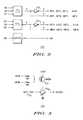
- FIG. 1is a block diagram illustrating one embodiment of a radio frequency switch, according to the present invention
- FIG. 2illustrates on embodiment of a logic diagram corresponding to the switch illustrated in FIG. 1 ;
- FIG. 3illustrates a logic diagram for one embodiment of a front-end amplifier, as illustrated in FIG. 1 ;
- FIG. 4is a simplified schematic diagram illustrating one embodiment of a satellite receiver incorporating the switch of FIG. 1 .
- Embodiments of the inventiongenerally provide a radio frequency (RF) switch for use in satellite receivers.
- the RF switchis an 8 ⁇ 2 RF switch that enables seamless change from a first transponder to a second transponder.
- the RF switchcomprises a single, four-layer printed circuit board that is placed and routed carefully for RF frequency impedance control and high isolation among signal paths, making the RF switch compact enough to be incorporated in a satellite receiver having a height of approximately one U rack (1.75 inches). In this case, isolation from undesired ports is measured from approximately 45 dB to more than 70 dB.
- the DC power supplyis a single +5 volts, and the total DC power requirement is measured less than approximately 1.2 watts.
- FIG. 1is a block diagram illustrating one embodiment of a radio frequency switch 100 , according to the present invention.
- the RF switch 100may be implemented, for example, in a satellite receiver.
- the RF switch 100comprises a plurality of input ports 102 1 - 102 8 (hereinafter collectively referred to as “input ports 102 ”) and a plurality of output ports 104 1 - 104 3 (hereinafter collectively referred to as “output ports 104 ”).
- input ports 102input ports 102 1 - 102 8
- output ports 104output ports 104 1 - 104 3
- the RF switch 100is illustrated as an 8 ⁇ 2 RF switch having eight input ports 102 and three output ports 104 (two primary and one backup), it will be appreciated by those skilled in the art that other configurations of an RF switch according to the present invention may comprise any number of input ports 102 and output ports 104 .
- each of a first output port 104 1 and a second output port 104 3independently selects one of the input ports 102 for digital satellite services.
- a third output port, output port 104 2selects from the first output port 104 1 and the second output port 104 3 as a backup port.
- this backup outputis coupled to an analog tuner and a demodulator (illustrated in further detail in FIG. 4 at 403 and 404 , respectively).
- combination logicis used to select the desired input port 102 for each output port 104 .
- this same combination logiccan be used to turn off unused RF amplifiers in the switch 100 .
- Each of the input ports 102is coupled to one of a set of front-end RF amplifiers 106 1 - 106 8 (hereinafter collectively referred to “amplifiers 106 ”).
- the amplifiers 106are broadband low-noise amplifiers.
- a transient voltage suppressor(not shown) is positioned in front of each amplifier 106 for protection.
- third-order intercept points of the amplifiers 106are high enough to have low intermodulation products at the strongest multiple-channels input signal.
- “low” intermodulation productsare at least approximately thirty-five dB below the desired signal levels, in order to reduce interferences.
- Each of the amplifiers 106is in turn coupled to one of a first set of power dividers 108 1 - 108 8 (hereinafter collectively referred to as “power dividers 108 ”).
- the power dividers 108split the signals from the input ports 102 .
- each power divider 108comprises three resistors for wide bandwidth and low cost.
- the amplifiers 106compensate for signal power loss due to the power dividers 108 .
- Each power divider 108is coupled to a plurality of resistor pads 110 1 - 110 16 (hereinafter collectively referred to as “resistor pads 110 ”).
- resistor pads 110are inserted after each power divider 108 to compensate for different lengths of striplines or microstrip transmission lines, so that unity insertion gain (within three dB because of tolerances of components) can be obtained from any input port 102 to any one of the output ports 104 (e.g., over approximately 950 MHz to approximately 2150 MHz).
- Unity insertion gainwill make the switch 100 transparent to tuners in a satellite receiver.
- the resistor pads 110are coupled to three stages of RF switches.
- a first stage of RF switches 112 1 - 112 8(hereinafter collectively referred to as “switches 112 ”) is directly coupled to the resistor pads 110 .
- the first stage of RF switchesis in turn coupled to a second stage of RF switches 114 1 - 114 4 (hereinafter collectively referred to as “switches 114 ”).
- the second stage of RF switchesis in turn coupled to a third stage of RF switches 116 1 - 116 2 (hereinafter collectively referred to as “switches 116 ”).
- the switches 112 , 114 , and 116 in each of the stagesare identical.
- the switches 112 , 114 , and 116are SP2T RF switches. In a further embodiment, the switches 112 , 114 , and 116 are gallium-arsenide (GaAs) monolithic microwave integrated circuit (MMIC) switches.
- GaAsgallium-arsenide
- MMICmonolithic microwave integrated circuit
- the first stage of RF switches 112comprises as many switches as there are input ports 102 .
- the second stage of RF switches 114comprises half as many switches as the first stage of RF switches 112
- the third stage of RF switches 116comprises half as many switches as the second stage of RF switches 114 .
- each switch in each stagereceives the output of two switches in the immediately previous stage (e.g., in the embodiment illustrated in FIG. 1 , switch 114 1 of the second stage receives the output of switches 112 1 and 112 3 of the first stage).
- the three stages of switchesdetermine which input port 102 will pass through to which output port 104 .
- the switches 112 , 114 , and 116are controlled by logic signals from outputs of two three- to eight-line logic decoders (denoted generally as 124 in FIG. 1 and as 124 1 - 124 2 in FIG. 2 ) and some inverters (denoted as 202 1 - 202 2 in FIG. 2 ), determined by six external control logic signals (denoted as S 10 , S 11 , S 12 , S 20 , S 21 , and S 22 in FIG. 1 ). Roughly half of the control logic signals (e.g., control logic signals S 10 , S 11 , and S 12 in FIG.
- control logic signal denoted as SANselects either the first output port 104 1 or the second output port 104 3 for the third, backup output port 104 2 .
- Each switch in the third stage of switches 116is coupled to one of a second set of back-end RF amplifiers 118 1 - 118 2 (hereinafter collectively referred to as “amplifiers 118 ”). These amplifiers 118 provide additional signal power gain, as well as isolation between the first output port 104 1 and the second output port 104 3 . Each of the amplifiers 118 is in turn coupled to one of a second set of power dividers 120 1 - 120 2 (hereinafter collectively referred to as “power dividers 120 ”).
- a lone RF switch 122selects either the first output port 104 1 or the second output port 104 3 for the third, backup output port 104 2 .
- the RF switch 122is an SP2T switch.
- the relatively compact, single board layout of the 8 ⁇ 2 RF switch 100does not require the connection of any internal coaxial cables when integrated into a satellite receiver. Because the lack of coaxial interconnection cables allows receiver space to be conserved, the switch 100 can be integrated in a compact satellite receiver (e.g., of approximately 1U rack height).
- the housing size of the 8 ⁇ 2 RF switch 100is approximately 6.5 inch long ⁇ 4 inch wide ⁇ 0.5 inch thick, which is smaller than the housing for a typical 8 ⁇ 1 switch.
- a 0.5 inch thicknessis the minimum required to accept F connectors, and a 6.5 inch length is defined by equally spacing eight F connectors while allowing external cables to be screwed and unscrewed by human fingers.
- the switch 100is capable of changing seamlessly between transponders of a satellite receiver.
- FIG. 4is a simplified schematic diagram illustrating one embodiment of a plurality of satellite receivers 400 1 - 400 N (hereinafter collectively referred to as “receivers 400 ”) incorporating the RF switch 100 of FIG. 1 .
- a plurality of power dividers 402 1 - 402 N(hereinafter collectively referred to as “power dividers 402 ”) split the signals from a plurality of antennae 401 1 - 401 N (hereinafter collectively referred to as “antennae 401 ”) into the receivers 400 (specifically into the input ports 102 of the switch 100 ).
- a plurality of tuners 403 1 - 403 3tune to satellite transponders from the output ports 104 of the switch 100 .
- a first tuner 403 1tunes to a first transponder from the first output port 104 1
- a second tuner 403 3tunes to a second transponder from the second output port 104 3
- a third tuner 403 2tunes to a backup transponder from the third, backup output port 104 2 .
- the output of each tuner 403is coupled to one of a plurality of demodulators 404 1 - 404 3 (hereinafter collectively referred to as “demodulators 404 ”).
- Video signals and audio signals from the demodulators 404are coupled to a video/audio switch 405 .
- the video/audio switch 405selects one pair of video and audio signals to provide satellite service. Because each tuner 403 is already tuned to a desired transponder, video and audio signals may be changed seamlessly without re-tuning the transponders.
- front-end amplifiers 106are turned off if their respective signal paths are not selected. In this way, only one—or at most two—of the front-end amplifiers 106 are turned on at a time.
- ferrite beadsdenoted in FIG. 1 as F 1 and F 2
- a capacitordenoted in FIG. 1 as C 1
- Thisprovides DC power to external low-noise down-converters at the satellite antennae, but blocks high frequencies between the first input port 102 1 and the first output port 104 1 .
- FIG. 3illustrates a logic diagram 300 for one embodiment of a front-end amplifier 106 M , as illustrated in FIG. 1 .
- the front-end amplifier 106 Mis one representative of the amplifiers 106 , and is coupled to a representative input port 102 M .
- the amplifier 106 Mreceives a plurality of control logic signals.
- the control logic signal denoted as AMP 1 Menables the amplifier 106 M when AMP 1 M is at logical LOW and disables the amplifier 106 M when AMP 1 M is at logical HIGH.
- AMP 1 Mis the inverted logic signal of OUT 1 M.
- control logic signal denoted as AMP 2 Menables the amplifier 106 M when AMP 2 M is at logical LOW and disables the amplifier 106 M when AMP 2 M is at logical HIGH.
- AMP 2 Mis the inverted logic signal of OUT 2 M.
- a PNP transistor 302is used to turn DC power to the amplifier 106 M on or off.
- the control logic signals AMP 1 M and AMP 2 Mare connected to the base of the transistor 302 , such that the transistor 302 is turned off if both of AMP 1 M and AMP 2 M are at logical HIGH.
- the first output port 104 1selects input port 102 3
- the second output port 104 3selects input port 102 7
- all of OUT 1 Mare LOW, except for OUT 13
- all of OUT 2 Mare LOW, except for OUT 27 .
- the first stage of RF switches 112will only pass input from input port 102 3 for the first output port 104 1 and input from input port 102 7 for the second output port 104 3 .
- all of AMP 1 Mare HIGH, except for AMP 13
- all of AMP 2 Mare HIGH, except for AMP 27 .
- all of the front-end RF amplifiers 106are turned off, except for the amplifier 106 3 coupled to input port 102 3 and the amplifier 106 7 coupled to input port 102 7 . If both the first output port 104 1 and the second output port 104 3 select input port 102 3 , then all of the front-end amplifiers 106 are turned off, except for the amplifier 106 3 coupled to input port 102 3 .
Landscapes
- Engineering & Computer Science (AREA)
- Physics & Mathematics (AREA)
- Astronomy & Astrophysics (AREA)
- Aviation & Aerospace Engineering (AREA)
- General Physics & Mathematics (AREA)
- Computer Networks & Wireless Communication (AREA)
- Signal Processing (AREA)
- Input Circuits Of Receivers And Coupling Of Receivers And Audio Equipment (AREA)
Abstract
Description
| TABLE 1 |
| Logic controls for first output port 1041selection |
| RF input port to | |||
| be selected | Logic signal S12 | Logic signal S11 | Logic signal S10 |
| 1021 | 0 | 0 | 0 |
| 1022 | 0 | 0 | 1 |
| 1023 | 0 | 1 | 0 |
| 1024 | 0 | 1 | 1 |
| 1025 | 1 | 0 | 0 |
| 1026 | 1 | 0 | 1 |
| 1027 | 1 | 1 | 0 |
| 1028 | 1 | 1 | 1 |
| TABLE 2 |
| Logic controls for second output port 1043selection |
| RF input port to | |||
| be selected | Logic signal S22 | Logic signal S21 | Logic signal S20 |
| 1021 | 0 | 0 | 0 |
| 1022 | 0 | 0 | 1 |
| 1023 | 0 | 1 | 0 |
| 1024 | 0 | 1 | 1 |
| 1025 | 1 | 0 | 0 |
| 1026 | 1 | 0 | 1 |
| 1027 | 1 | 1 | 0 |
| 1028 | 1 | 1 | 1 |
| TABLE 3 |
| Logic controls for third output port 1042selection |
| Port A output | Logic signal SAN | ||
| 1041 | 0 | ||
| 1043 | 1 | ||
Claims (18)
Priority Applications (1)
| Application Number | Priority Date | Filing Date | Title |
|---|---|---|---|
| US11/831,136US8174337B2 (en) | 2007-07-31 | 2007-07-31 | Radio frequency switch for use in satellite receivers |
Applications Claiming Priority (1)
| Application Number | Priority Date | Filing Date | Title |
|---|---|---|---|
| US11/831,136US8174337B2 (en) | 2007-07-31 | 2007-07-31 | Radio frequency switch for use in satellite receivers |
Publications (2)
| Publication Number | Publication Date |
|---|---|
| US20120064823A1 US20120064823A1 (en) | 2012-03-15 |
| US8174337B2true US8174337B2 (en) | 2012-05-08 |
Family
ID=45807181
Family Applications (1)
| Application Number | Title | Priority Date | Filing Date |
|---|---|---|---|
| US11/831,136Active2030-12-14US8174337B2 (en) | 2007-07-31 | 2007-07-31 | Radio frequency switch for use in satellite receivers |
Country Status (1)
| Country | Link |
|---|---|
| US (1) | US8174337B2 (en) |
Cited By (1)
| Publication number | Priority date | Publication date | Assignee | Title |
|---|---|---|---|---|
| US20160065136A1 (en)* | 2014-09-02 | 2016-03-03 | Quintech Electronics & Communications, Inc. | Modular RF Matrix Switch |
Families Citing this family (2)
| Publication number | Priority date | Publication date | Assignee | Title |
|---|---|---|---|---|
| CN102668388A (en)* | 2009-12-22 | 2012-09-12 | 航空力学服务有限公司 | Multiple Satellite Modem System Utilizing a Single Antenna |
| US10084509B2 (en)* | 2015-12-01 | 2018-09-25 | Hughes Network Systems, Llc | Flexible redundancy using RF switch matrix |
Citations (5)
| Publication number | Priority date | Publication date | Assignee | Title |
|---|---|---|---|---|
| US3833866A (en) | 1972-08-07 | 1974-09-03 | Int Standard Electric Corp | Microwave switching matrix |
| US5428814A (en)* | 1992-08-14 | 1995-06-27 | Alcatel Espace | Space communications apparatus employing switchable band filters for transparently switching signals on board a communications satellite, payload architectures using such apparatus, and methods of implementing the apparatus and the architectures |
| US5828268A (en)* | 1997-06-05 | 1998-10-27 | Hughes Electronics Corporation | Microwave switches and redundant switching systems |
| US20060091972A1 (en) | 2004-11-02 | 2006-05-04 | Microwave Photonics, Inc. | Distributed matrix switch |
| US7593703B2 (en)* | 2005-12-12 | 2009-09-22 | Alcatel-Lucent | Frequency switch for multiband power amplifier applications and multiband/multistandard power amplifier module |
- 2007
- 2007-07-31USUS11/831,136patent/US8174337B2/enactiveActive
Patent Citations (5)
| Publication number | Priority date | Publication date | Assignee | Title |
|---|---|---|---|---|
| US3833866A (en) | 1972-08-07 | 1974-09-03 | Int Standard Electric Corp | Microwave switching matrix |
| US5428814A (en)* | 1992-08-14 | 1995-06-27 | Alcatel Espace | Space communications apparatus employing switchable band filters for transparently switching signals on board a communications satellite, payload architectures using such apparatus, and methods of implementing the apparatus and the architectures |
| US5828268A (en)* | 1997-06-05 | 1998-10-27 | Hughes Electronics Corporation | Microwave switches and redundant switching systems |
| US20060091972A1 (en) | 2004-11-02 | 2006-05-04 | Microwave Photonics, Inc. | Distributed matrix switch |
| US7593703B2 (en)* | 2005-12-12 | 2009-09-22 | Alcatel-Lucent | Frequency switch for multiband power amplifier applications and multiband/multistandard power amplifier module |
Cited By (2)
| Publication number | Priority date | Publication date | Assignee | Title |
|---|---|---|---|---|
| US20160065136A1 (en)* | 2014-09-02 | 2016-03-03 | Quintech Electronics & Communications, Inc. | Modular RF Matrix Switch |
| US9819317B2 (en)* | 2014-09-02 | 2017-11-14 | Quintech Electronics & Communications, Inc. | Modular RF matrix switch |
Also Published As
| Publication number | Publication date |
|---|---|
| US20120064823A1 (en) | 2012-03-15 |
Similar Documents
| Publication | Publication Date | Title |
|---|---|---|
| US11929824B2 (en) | Satellite signal frequency translation and stacking | |
| US6018644A (en) | Low-loss, fault-tolerant antenna interface unit | |
| EP1317073B1 (en) | Tuner arrangement and set top box | |
| US20070111661A1 (en) | Integrated Crosspoint Switch with Band Translation | |
| US8300681B2 (en) | Translational switching system and signal distribution system employing same | |
| US6970688B2 (en) | Local oscillator signal divider and low-noise converter employing the same | |
| EP1886411A1 (en) | Method and apparatus for distributing multiple signal inputs to multiple integrated circuits | |
| US8174337B2 (en) | Radio frequency switch for use in satellite receivers | |
| US6020936A (en) | TV/FM receiver for multimedia applications | |
| US7610033B2 (en) | Radio frequency tuner | |
| US9548778B2 (en) | Device and method for switchably routing down-converted RF signals | |
| US7787851B2 (en) | Circuit arrangement with radio-frequency mixer, and receiver arrangement with the circuit arrangement | |
| JPH09200068A (en) | Television signal changeover output circuit | |
| KR0115811Y1 (en) | Dual switching output low noise block circuit | |
| JP2002359571A (en) | Television tuner | |
| JP2007142838A (en) | Electronic tuner |
Legal Events
| Date | Code | Title | Description |
|---|---|---|---|
| AS | Assignment | Owner name:GENERAL INSTRUMENT CORPORATION, PENNSYLVANIA Free format text:ASSIGNMENT OF ASSIGNORS INTEREST;ASSIGNOR:CHEN, KEMING J.;REEL/FRAME:019650/0457 Effective date:20070730 | |
| STCF | Information on status: patent grant | Free format text:PATENTED CASE | |
| AS | Assignment | Owner name:BANK OF AMERICA, N.A., AS ADMINISTRATIVE AGENT, IL Free format text:SECURITY AGREEMENT;ASSIGNORS:ARRIS GROUP, INC.;ARRIS ENTERPRISES, INC.;ARRIS SOLUTIONS, INC.;AND OTHERS;REEL/FRAME:030498/0023 Effective date:20130417 Owner name:BANK OF AMERICA, N.A., AS ADMINISTRATIVE AGENT, ILLINOIS Free format text:SECURITY AGREEMENT;ASSIGNORS:ARRIS GROUP, INC.;ARRIS ENTERPRISES, INC.;ARRIS SOLUTIONS, INC.;AND OTHERS;REEL/FRAME:030498/0023 Effective date:20130417 | |
| AS | Assignment | Owner name:ARRIS TECHNOLOGY, INC., GEORGIA Free format text:MERGER AND CHANGE OF NAME;ASSIGNOR:GENERAL INSTRUMENT CORPORATION;REEL/FRAME:035176/0620 Effective date:20150101 Owner name:ARRIS TECHNOLOGY, INC., GEORGIA Free format text:MERGER AND CHANGE OF NAME;ASSIGNORS:GENERAL INSTRUMENT CORPORATION;GENERAL INSTRUMENT CORPORATION;REEL/FRAME:035176/0620 Effective date:20150101 | |
| FPAY | Fee payment | Year of fee payment:4 | |
| AS | Assignment | Owner name:ARRIS ENTERPRISES, INC., GEORGIA Free format text:ASSIGNMENT OF ASSIGNORS INTEREST;ASSIGNOR:ARRIS TECHNOLOGY, INC;REEL/FRAME:037328/0341 Effective date:20151214 | |
| AS | Assignment | Owner name:ARRIS HOLDINGS CORP. OF ILLINOIS, INC., PENNSYLVAN Free format text:TERMINATION AND RELEASE OF SECURITY INTEREST IN PATENTS;ASSIGNOR:BANK OF AMERICA, N.A., AS ADMINISTRATIVE AGENT;REEL/FRAME:048825/0294 Effective date:20190404 Owner name:GENERAL INSTRUMENT INTERNATIONAL HOLDINGS, INC., P Free format text:TERMINATION AND RELEASE OF SECURITY INTEREST IN PATENTS;ASSIGNOR:BANK OF AMERICA, N.A., AS ADMINISTRATIVE AGENT;REEL/FRAME:048825/0294 Effective date:20190404 Owner name:MOTOROLA WIRELINE NETWORKS, INC., PENNSYLVANIA Free format text:TERMINATION AND RELEASE OF SECURITY INTEREST IN PATENTS;ASSIGNOR:BANK OF AMERICA, N.A., AS ADMINISTRATIVE AGENT;REEL/FRAME:048825/0294 Effective date:20190404 Owner name:NEXTLEVEL SYSTEMS (PUERTO RICO), INC., PENNSYLVANI Free format text:TERMINATION AND RELEASE OF SECURITY INTEREST IN PATENTS;ASSIGNOR:BANK OF AMERICA, N.A., AS ADMINISTRATIVE AGENT;REEL/FRAME:048825/0294 Effective date:20190404 Owner name:ARRIS GROUP, INC., PENNSYLVANIA Free format text:TERMINATION AND RELEASE OF SECURITY INTEREST IN PATENTS;ASSIGNOR:BANK OF AMERICA, N.A., AS ADMINISTRATIVE AGENT;REEL/FRAME:048825/0294 Effective date:20190404 Owner name:ACADIA AIC, INC., PENNSYLVANIA Free format text:TERMINATION AND RELEASE OF SECURITY INTEREST IN PATENTS;ASSIGNOR:BANK OF AMERICA, N.A., AS ADMINISTRATIVE AGENT;REEL/FRAME:048825/0294 Effective date:20190404 Owner name:MODULUS VIDEO, INC., PENNSYLVANIA Free format text:TERMINATION AND RELEASE OF SECURITY INTEREST IN PATENTS;ASSIGNOR:BANK OF AMERICA, N.A., AS ADMINISTRATIVE AGENT;REEL/FRAME:048825/0294 Effective date:20190404 Owner name:GENERAL INSTRUMENT CORPORATION, PENNSYLVANIA Free format text:TERMINATION AND RELEASE OF SECURITY INTEREST IN PATENTS;ASSIGNOR:BANK OF AMERICA, N.A., AS ADMINISTRATIVE AGENT;REEL/FRAME:048825/0294 Effective date:20190404 Owner name:QUANTUM BRIDGE COMMUNICATIONS, INC., PENNSYLVANIA Free format text:TERMINATION AND RELEASE OF SECURITY INTEREST IN PATENTS;ASSIGNOR:BANK OF AMERICA, N.A., AS ADMINISTRATIVE AGENT;REEL/FRAME:048825/0294 Effective date:20190404 Owner name:LEAPSTONE SYSTEMS, INC., PENNSYLVANIA Free format text:TERMINATION AND RELEASE OF SECURITY INTEREST IN PATENTS;ASSIGNOR:BANK OF AMERICA, N.A., AS ADMINISTRATIVE AGENT;REEL/FRAME:048825/0294 Effective date:20190404 Owner name:SETJAM, INC., PENNSYLVANIA Free format text:TERMINATION AND RELEASE OF SECURITY INTEREST IN PATENTS;ASSIGNOR:BANK OF AMERICA, N.A., AS ADMINISTRATIVE AGENT;REEL/FRAME:048825/0294 Effective date:20190404 Owner name:CCE SOFTWARE LLC, PENNSYLVANIA Free format text:TERMINATION AND RELEASE OF SECURITY INTEREST IN PATENTS;ASSIGNOR:BANK OF AMERICA, N.A., AS ADMINISTRATIVE AGENT;REEL/FRAME:048825/0294 Effective date:20190404 Owner name:THE GI REALTY TRUST 1996, PENNSYLVANIA Free format text:TERMINATION AND RELEASE OF SECURITY INTEREST IN PATENTS;ASSIGNOR:BANK OF AMERICA, N.A., AS ADMINISTRATIVE AGENT;REEL/FRAME:048825/0294 Effective date:20190404 Owner name:IMEDIA CORPORATION, PENNSYLVANIA Free format text:TERMINATION AND RELEASE OF SECURITY INTEREST IN PATENTS;ASSIGNOR:BANK OF AMERICA, N.A., AS ADMINISTRATIVE AGENT;REEL/FRAME:048825/0294 Effective date:20190404 Owner name:TEXSCAN CORPORATION, PENNSYLVANIA Free format text:TERMINATION AND RELEASE OF SECURITY INTEREST IN PATENTS;ASSIGNOR:BANK OF AMERICA, N.A., AS ADMINISTRATIVE AGENT;REEL/FRAME:048825/0294 Effective date:20190404 Owner name:SUNUP DESIGN SYSTEMS, INC., PENNSYLVANIA Free format text:TERMINATION AND RELEASE OF SECURITY INTEREST IN PATENTS;ASSIGNOR:BANK OF AMERICA, N.A., AS ADMINISTRATIVE AGENT;REEL/FRAME:048825/0294 Effective date:20190404 Owner name:4HOME, INC., PENNSYLVANIA Free format text:TERMINATION AND RELEASE OF SECURITY INTEREST IN PATENTS;ASSIGNOR:BANK OF AMERICA, N.A., AS ADMINISTRATIVE AGENT;REEL/FRAME:048825/0294 Effective date:20190404 Owner name:JERROLD DC RADIO, INC., PENNSYLVANIA Free format text:TERMINATION AND RELEASE OF SECURITY INTEREST IN PATENTS;ASSIGNOR:BANK OF AMERICA, N.A., AS ADMINISTRATIVE AGENT;REEL/FRAME:048825/0294 Effective date:20190404 Owner name:UCENTRIC SYSTEMS, INC., PENNSYLVANIA Free format text:TERMINATION AND RELEASE OF SECURITY INTEREST IN PATENTS;ASSIGNOR:BANK OF AMERICA, N.A., AS ADMINISTRATIVE AGENT;REEL/FRAME:048825/0294 Effective date:20190404 Owner name:AEROCAST, INC., PENNSYLVANIA Free format text:TERMINATION AND RELEASE OF SECURITY INTEREST IN PATENTS;ASSIGNOR:BANK OF AMERICA, N.A., AS ADMINISTRATIVE AGENT;REEL/FRAME:048825/0294 Effective date:20190404 Owner name:ARRIS KOREA, INC., PENNSYLVANIA Free format text:TERMINATION AND RELEASE OF SECURITY INTEREST IN PATENTS;ASSIGNOR:BANK OF AMERICA, N.A., AS ADMINISTRATIVE AGENT;REEL/FRAME:048825/0294 Effective date:20190404 Owner name:BIG BAND NETWORKS, INC., PENNSYLVANIA Free format text:TERMINATION AND RELEASE OF SECURITY INTEREST IN PATENTS;ASSIGNOR:BANK OF AMERICA, N.A., AS ADMINISTRATIVE AGENT;REEL/FRAME:048825/0294 Effective date:20190404 Owner name:ARRIS SOLUTIONS, INC., PENNSYLVANIA Free format text:TERMINATION AND RELEASE OF SECURITY INTEREST IN PATENTS;ASSIGNOR:BANK OF AMERICA, N.A., AS ADMINISTRATIVE AGENT;REEL/FRAME:048825/0294 Effective date:20190404 Owner name:GIC INTERNATIONAL HOLDCO LLC, PENNSYLVANIA Free format text:TERMINATION AND RELEASE OF SECURITY INTEREST IN PATENTS;ASSIGNOR:BANK OF AMERICA, N.A., AS ADMINISTRATIVE AGENT;REEL/FRAME:048825/0294 Effective date:20190404 Owner name:NETOPIA, INC., PENNSYLVANIA Free format text:TERMINATION AND RELEASE OF SECURITY INTEREST IN PATENTS;ASSIGNOR:BANK OF AMERICA, N.A., AS ADMINISTRATIVE AGENT;REEL/FRAME:048825/0294 Effective date:20190404 Owner name:ARRIS ENTERPRISES, INC., PENNSYLVANIA Free format text:TERMINATION AND RELEASE OF SECURITY INTEREST IN PATENTS;ASSIGNOR:BANK OF AMERICA, N.A., AS ADMINISTRATIVE AGENT;REEL/FRAME:048825/0294 Effective date:20190404 Owner name:POWER GUARD, INC., PENNSYLVANIA Free format text:TERMINATION AND RELEASE OF SECURITY INTEREST IN PATENTS;ASSIGNOR:BANK OF AMERICA, N.A., AS ADMINISTRATIVE AGENT;REEL/FRAME:048825/0294 Effective date:20190404 Owner name:GENERAL INSTRUMENT AUTHORIZATION SERVICES, INC., P Free format text:TERMINATION AND RELEASE OF SECURITY INTEREST IN PATENTS;ASSIGNOR:BANK OF AMERICA, N.A., AS ADMINISTRATIVE AGENT;REEL/FRAME:048825/0294 Effective date:20190404 Owner name:GIC INTERNATIONAL CAPITAL LLC, PENNSYLVANIA Free format text:TERMINATION AND RELEASE OF SECURITY INTEREST IN PATENTS;ASSIGNOR:BANK OF AMERICA, N.A., AS ADMINISTRATIVE AGENT;REEL/FRAME:048825/0294 Effective date:20190404 Owner name:BROADBUS TECHNOLOGIES, INC., PENNSYLVANIA Free format text:TERMINATION AND RELEASE OF SECURITY INTEREST IN PATENTS;ASSIGNOR:BANK OF AMERICA, N.A., AS ADMINISTRATIVE AGENT;REEL/FRAME:048825/0294 Effective date:20190404 Owner name:ARRIS HOLDINGS CORP. OF ILLINOIS, INC., PENNSYLVANIA Free format text:TERMINATION AND RELEASE OF SECURITY INTEREST IN PATENTS;ASSIGNOR:BANK OF AMERICA, N.A., AS ADMINISTRATIVE AGENT;REEL/FRAME:048825/0294 Effective date:20190404 Owner name:GENERAL INSTRUMENT INTERNATIONAL HOLDINGS, INC., PENNSYLVANIA Free format text:TERMINATION AND RELEASE OF SECURITY INTEREST IN PATENTS;ASSIGNOR:BANK OF AMERICA, N.A., AS ADMINISTRATIVE AGENT;REEL/FRAME:048825/0294 Effective date:20190404 Owner name:GENERAL INSTRUMENT AUTHORIZATION SERVICES, INC., PENNSYLVANIA Free format text:TERMINATION AND RELEASE OF SECURITY INTEREST IN PATENTS;ASSIGNOR:BANK OF AMERICA, N.A., AS ADMINISTRATIVE AGENT;REEL/FRAME:048825/0294 Effective date:20190404 Owner name:NEXTLEVEL SYSTEMS (PUERTO RICO), INC., PENNSYLVANIA Free format text:TERMINATION AND RELEASE OF SECURITY INTEREST IN PATENTS;ASSIGNOR:BANK OF AMERICA, N.A., AS ADMINISTRATIVE AGENT;REEL/FRAME:048825/0294 Effective date:20190404 | |
| AS | Assignment | Owner name:ARRIS ENTERPRISES LLC, GEORGIA Free format text:CHANGE OF NAME;ASSIGNOR:ARRIS ENTERPRISES, INC.;REEL/FRAME:049649/0062 Effective date:20151231 | |
| AS | Assignment | Owner name:WILMINGTON TRUST, NATIONAL ASSOCIATION, AS COLLATE Free format text:PATENT SECURITY AGREEMENT;ASSIGNOR:ARRIS ENTERPRISES LLC;REEL/FRAME:049820/0495 Effective date:20190404 Owner name:JPMORGAN CHASE BANK, N.A., NEW YORK Free format text:ABL SECURITY AGREEMENT;ASSIGNORS:COMMSCOPE, INC. OF NORTH CAROLINA;COMMSCOPE TECHNOLOGIES LLC;ARRIS ENTERPRISES LLC;AND OTHERS;REEL/FRAME:049892/0396 Effective date:20190404 Owner name:JPMORGAN CHASE BANK, N.A., NEW YORK Free format text:TERM LOAN SECURITY AGREEMENT;ASSIGNORS:COMMSCOPE, INC. OF NORTH CAROLINA;COMMSCOPE TECHNOLOGIES LLC;ARRIS ENTERPRISES LLC;AND OTHERS;REEL/FRAME:049905/0504 Effective date:20190404 Owner name:WILMINGTON TRUST, NATIONAL ASSOCIATION, AS COLLATERAL AGENT, CONNECTICUT Free format text:PATENT SECURITY AGREEMENT;ASSIGNOR:ARRIS ENTERPRISES LLC;REEL/FRAME:049820/0495 Effective date:20190404 | |
| MAFP | Maintenance fee payment | Free format text:PAYMENT OF MAINTENANCE FEE, 8TH YEAR, LARGE ENTITY (ORIGINAL EVENT CODE: M1552); ENTITY STATUS OF PATENT OWNER: LARGE ENTITY Year of fee payment:8 | |
| AS | Assignment | Owner name:WILMINGTON TRUST, DELAWARE Free format text:SECURITY INTEREST;ASSIGNORS:ARRIS SOLUTIONS, INC.;ARRIS ENTERPRISES LLC;COMMSCOPE TECHNOLOGIES LLC;AND OTHERS;REEL/FRAME:060752/0001 Effective date:20211115 | |
| AS | Assignment | Owner name:ARRIS ENTERPRISES, INC., GEORGIA Free format text:ASSIGNMENT OF ASSIGNORS INTEREST;ASSIGNOR:ARRIS TECHNOLOGY, INC.;REEL/FRAME:060791/0583 Effective date:20151214 | |
| MAFP | Maintenance fee payment | Free format text:PAYMENT OF MAINTENANCE FEE, 12TH YEAR, LARGE ENTITY (ORIGINAL EVENT CODE: M1553); ENTITY STATUS OF PATENT OWNER: LARGE ENTITY Year of fee payment:12 | |
| AS | Assignment | Owner name:APOLLO ADMINISTRATIVE AGENCY LLC, NEW YORK Free format text:SECURITY INTEREST;ASSIGNORS:ARRIS ENTERPRISES LLC;COMMSCOPE TECHNOLOGIES LLC;COMMSCOPE INC., OF NORTH CAROLINA;AND OTHERS;REEL/FRAME:069889/0114 Effective date:20241217 | |
| AS | Assignment | Owner name:RUCKUS WIRELESS, LLC (F/K/A RUCKUS WIRELESS, INC.), NORTH CAROLINA Free format text:RELEASE OF SECURITY INTEREST AT REEL/FRAME 049905/0504;ASSIGNOR:JPMORGAN CHASE BANK, N.A., AS COLLATERAL AGENT;REEL/FRAME:071477/0255 Effective date:20241217 Owner name:COMMSCOPE TECHNOLOGIES LLC, NORTH CAROLINA Free format text:RELEASE OF SECURITY INTEREST AT REEL/FRAME 049905/0504;ASSIGNOR:JPMORGAN CHASE BANK, N.A., AS COLLATERAL AGENT;REEL/FRAME:071477/0255 Effective date:20241217 Owner name:COMMSCOPE, INC. OF NORTH CAROLINA, NORTH CAROLINA Free format text:RELEASE OF SECURITY INTEREST AT REEL/FRAME 049905/0504;ASSIGNOR:JPMORGAN CHASE BANK, N.A., AS COLLATERAL AGENT;REEL/FRAME:071477/0255 Effective date:20241217 Owner name:ARRIS SOLUTIONS, INC., NORTH CAROLINA Free format text:RELEASE OF SECURITY INTEREST AT REEL/FRAME 049905/0504;ASSIGNOR:JPMORGAN CHASE BANK, N.A., AS COLLATERAL AGENT;REEL/FRAME:071477/0255 Effective date:20241217 Owner name:ARRIS TECHNOLOGY, INC., NORTH CAROLINA Free format text:RELEASE OF SECURITY INTEREST AT REEL/FRAME 049905/0504;ASSIGNOR:JPMORGAN CHASE BANK, N.A., AS COLLATERAL AGENT;REEL/FRAME:071477/0255 Effective date:20241217 Owner name:ARRIS ENTERPRISES LLC (F/K/A ARRIS ENTERPRISES, INC.), NORTH CAROLINA Free format text:RELEASE OF SECURITY INTEREST AT REEL/FRAME 049905/0504;ASSIGNOR:JPMORGAN CHASE BANK, N.A., AS COLLATERAL AGENT;REEL/FRAME:071477/0255 Effective date:20241217 |