US8172954B2 - Apparatus for simultaneous two-disk scrubbing and washing - Google Patents
Apparatus for simultaneous two-disk scrubbing and washingDownload PDFInfo
- Publication number
- US8172954B2 US8172954B2US10/435,293US43529303AUS8172954B2US 8172954 B2US8172954 B2US 8172954B2US 43529303 AUS43529303 AUS 43529303AUS 8172954 B2US8172954 B2US 8172954B2
- Authority
- US
- United States
- Prior art keywords
- disks
- pair
- disk
- selected carrier
- gap
- Prior art date
- Legal status (The legal status is an assumption and is not a legal conclusion. Google has not performed a legal analysis and makes no representation as to the accuracy of the status listed.)
- Expired - Fee Related, expires
Links
Images


Classifications
- G—PHYSICS
- G11—INFORMATION STORAGE
- G11B—INFORMATION STORAGE BASED ON RELATIVE MOVEMENT BETWEEN RECORD CARRIER AND TRANSDUCER
- G11B23/00—Record carriers not specific to the method of recording or reproducing; Accessories, e.g. containers, specially adapted for co-operation with the recording or reproducing apparatus ; Intermediate mediums; Apparatus or processes specially adapted for their manufacture
- G11B23/50—Reconditioning of record carriers; Cleaning of record carriers ; Carrying-off electrostatic charges
- G11B23/505—Reconditioning of record carriers; Cleaning of record carriers ; Carrying-off electrostatic charges of disk carriers
- G—PHYSICS
- G11—INFORMATION STORAGE
- G11B—INFORMATION STORAGE BASED ON RELATIVE MOVEMENT BETWEEN RECORD CARRIER AND TRANSDUCER
- G11B5/00—Recording by magnetisation or demagnetisation of a record carrier; Reproducing by magnetic means; Record carriers therefor
- G11B5/84—Processes or apparatus specially adapted for manufacturing record carriers
- G11B5/8404—Processes or apparatus specially adapted for manufacturing record carriers manufacturing base layers
- Y—GENERAL TAGGING OF NEW TECHNOLOGICAL DEVELOPMENTS; GENERAL TAGGING OF CROSS-SECTIONAL TECHNOLOGIES SPANNING OVER SEVERAL SECTIONS OF THE IPC; TECHNICAL SUBJECTS COVERED BY FORMER USPC CROSS-REFERENCE ART COLLECTIONS [XRACs] AND DIGESTS
- Y10—TECHNICAL SUBJECTS COVERED BY FORMER USPC
- Y10S—TECHNICAL SUBJECTS COVERED BY FORMER USPC CROSS-REFERENCE ART COLLECTIONS [XRACs] AND DIGESTS
- Y10S134/00—Cleaning and liquid contact with solids
- Y10S134/902—Semiconductor wafer
Definitions
- the present inventionrelates to the processing of hard memory disks, typically used in hard disk drives. More specifically, it relates to various methods and apparatus for simultaneously cleaning the active surfaces of two single-sided hard memory disks.
- Hard disk drivesare an efficient and cost effective solution for data storage. Depending upon the requirements of the particular application, a disk drive may include anywhere from one to eight hard disks and data may be stored on one or both surfaces of each disk. While hard disk drives are traditionally thought of as a component of a personal computer or as a network server, usage has expanded to include other storage applications such as set top boxes for recording and time shifting of television programs, personal digital assistants, cameras, music players and other consumer electronic devices, each having differing information storage capacity requirements.
- hard memory disksare produced with functional magnetic recording capabilities on both sides or surfaces of the disk.
- these hard disksare produced by subjecting both sides of a raw material substrate disk, such as glass, aluminum or some other suitable material, to numerous manufacturing processes. Active materials are deposited on both sides of the substrate disk and both sides of the disk are subject to full processing such that both sides of the disk may be referred to as active or functional from a memory storage stand point. The end result is that both sides of the finished disk have the necessary materials and characteristics required to effect magnetic recording and provide data storage. These are generally referred to as double-sided process disks. Assuming both surfaces pass certification testing and have no defects, both sides of the disk may be referred to as active or functional for memory storage purposes. These disks are referred as double-sided test pass disks. Double-sided test pass disks may be used in a disk drive for double-sided recording.
- the substrate disksare initially subjected to data zone texturing.
- Texturingprepares the surfaces of the substrate disks to receive layers of materials which will provide the active or memory storage capabilities on each disk surface.
- Texturingmay typically be accomplished in two ways: fixed abrasive texturing or free abrasive texturing.
- Fixed abrasive texturingis analogous to sanding, in which a fine grade sand paper or fabric is pressed against both sides of a spinning substrate disk to roughen or texturize both surfaces.
- Free abrasive texturinginvolves applying a rough woven fabric against the disk surfaces in the presence of a slurry.
- the slurrytypically contains diamond particles, which perform the texturing, a coolant to reduce heat generated in the texturing process and deionized water as the base solution.
- Texturingis typically followed by washing to remove particulate generated during texturing. Washing is a multi-stage process and usually includes scrubbing of the disk surfaces.
- the textured substrate disksare then subjected to a drying process. Drying is performed on an entire cassette of disk drives at a time. Following drying, the textured substrate disks are subjected to laser zone texturing. Laser zone texturing does not involve physically contacting and applying pressure against the substrate disk surfaces like data zone texturing.
- a laser beamis focused on and interacts with discrete portions of the disk surface, primarily to create an array of bumps for the head and slider assembly to land on and take off from.
- Laser zone texturingis performed one disk at a time.
- the disksare then washed again.
- the disksare individually subjected to a process which adds layers of material to both surfaces for purposes of creating data storage capabilities. This can be accomplished by sputtering, deposition or by other techniques known to persons of skill in the art.
- a lubricant layertypically is applied. The lubrication process can be accomplished by subjecting an entire cassette of disks to a liquid lubricant; it does not need to be done one disk at a time.
- the disksare individually subjected to surface burnishing to remove asperities, enhance bonding of the lubricant to the disk surface and otherwise provide a generally uniform finish to the disk surface.
- the disksare subjected to various types of testing. Examples of testing include glide testing to find and remove disks with asperities that could affect flying at the head/slider assembly and certification testing which is writing to and reading from the disk surfaces. Certification testing is also used to locate and remove disks with defects that make the surface unuseable for data storage.
- the finished diskscan then be subjected to a servo-writing process and placed in disk drives, or placed in disk drives then subjected to servo-writing.
- the data zone texturing, laser zone texturing, scrubbing, sputtering, burnishing and testing processesare done one disk at a time, with each surface of a single disk being processed simultaneously.
- disk drive manufacturerreduces its cost by eliminating the mechanical and electrical components needed to access the unused disk surface.
- These disk drivesare referred to as single-side drives and are typically used in low-end or economy disk drives to appeal to the low cost end of the marketplace. Although this approach may reduce some cost, it does not reduce the wasted cost of manufacturing the unused storage surface of each disk. Thus, substantial savings can be achieved by not only manufacturing disks with a single active or functional side, but doing so in a cost-effective manner.
- a single-sided diskhas only one functional memory surface with active recording materials. It is not a double-sided process disk where one side is not accessed or where one side has failed testing. Rather, manufacturing processes are applied in a controlled manner only to one side of the disk using unique single-sided processing techniques. In contrast to conventional double-sided disks, active recording materials are only applied to, and full processing is only conducted on, one side of the disk. Thus, substantial savings are achieved by eliminating processing the second side of each disk.
- FIG. 1shows a side-by-side schematic representation of the processing of one double-sided disk D d , depicted on the left side of FIG. 1 , versus the simultaneous processing of two single-sided disks D s , depicted on the right side of FIG. 1 .
- the double-sided disk or the two single-sided disksare subjected to the same process steps 1 through N, but the single-sided disk processing produces two disks in the same time the double-sided disk processing produces one disk.
- a benefit provided by simultaneous single-sided processing of disksis a substantial cost savings achieved by eliminating the application of materials to and processing of one side of each disk.
- a further, and potentially significant cost savingscan be achieved by utilizing existing double-sided disk processing equipment, with limited modification, to process pairs of single-sided disks.
- a still further benefitis a substantial increase in production (or reduction in processing time depending upon perspective).
- the simultaneous processingis achieved by combining two substrate disks together into a substrate disk pair or disk pair.
- a disk pairis two substrate disks that are oriented in a back-to-back relationship with the back-to-back surfaces either in direct physical contact or closely adjacent with a slight separation. The separation can be achieved with or without an intervening spacer.
- the substrate disk pairprogresses through each process step in much the same way as one double-sided disk, but with only the outwardly facing surface of each disk in the pair being subjected to the full process. Thus, the outwardly facing surface of each pair becomes the active or functional surface and the inwardly facing surface of each pair remain inactive or non-functional.
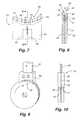
- FIG. 2a cross-section of a pair of gap-merged disks is shown.
- the R-sideactive or functional side
- the L-sideinactive or nonfunctional side
- FIG. 3a cross-section of a pair of concentric contact merged disks is shown in FIG. 3 .
- the relative orientation of the R-side and L-side of each diskremains the same, however, the L-side of each disk of the pair are in contact and the outer and inner perimeter P of each disk is aligned with the outer and inner perimeter P of the other disk.
- FIG. 4A conventional double-sided disk is shown in FIG. 4 .
- the left side surfaceis referred to as the “A” side and the right side surface is referred to as the “B” side. Both the A and B sides are subjected to processing, including the addition of active or magnetic materials.
- the R-side of each disk in a pair of disksis oriented on the outside of the pair and is subjected to processing in the same fashion as the A and B sides of a double-sided disk.
- the L-side of each disk in a pair of disksis oriented on the inside of the pair and is not subjected to full processing in the same fashion as the A and B sides of a double-sided disk.
- the benefit provided by the present inventionis an increased output in the production of finished disks achieved by cleaning and scrubbing two single-sided disks simultaneously.
- Another benefitis that, with limited modifications, the present invention can utilize existing processing equipment originally designed and built to clean and scrub double-sided disks for the processing of pairs of single-sided disks. This results in substantial capital equipment savings which would otherwise be spent unnecessarily modifying existing equipment or creating new equipment for cleaning and scrubbing single-sided disks.
- the present inventionis generally directed to methods and apparatus for cleaning and scrubbing the surface of two single-sided disks simultaneously.
- single-sided disk manufacturingand, more specifically, in the cleaning and scrubbing process, it is preferable to process the disks in pairs.
- the inactive or L-side surface of each disk within a pair of disksabuts the L-side surface of the other disk. This allows the outside surface, the R-side surface or active surface of each disk, to be cleaned simultaneously utilizing generally the same cleaning and scrubbing process equipment used to clean a single double-sided disk.
- a pair of gap merge disksare removed from a carrier containing a plurality of pairs of disks.
- the removed pair of disksis transferred to a cleaning and scrubbing zone where the upper outer edge of each disk contacts a pair of edge rollers.
- the edge rollersare configured to reposition the disks into a concentric contact merge orientation.
- a scrub brushis brought in contact with the R-side surface of each disk, further reorienting the disk pair into a concentric contact merge orientation by removing the remaining space between the disks.
- the edge rollersthen rotate to impart a rotation to the pair of disks.
- the rotationmay be clockwise or counter-clockwise.
- the scrubbing brushesrotate upwardly to force the disk pair against the edge rollers.
- a cleaning solutionis also applied to the disks and brushes. This process cleans and scrubs the R-side surface of each disk within the disk pair for a predetermined time period.
- a certain amount of stiction between the contact merge disksis beneficial to ensure unified movement of the two disks. Stiction between the disks is enhanced by the fact that the L-side surfaces are relatively flat, the presence of a liquid film or layer between the contact merge disks and because of the inwardly and oppositely directed forces applied by the scrubbing brushes on the outside surfaces of each of the disks.
- the film of water between the disksacts as an adhesive.
- One way in which to create the liquid layer between the disksis to spray a fine mist between the disks while they are in a gap merge orientation.
- a lower lift saddle and upper guide saddleare positioned adjacent to the pair of disks for purposes of securing the position of the disk pair and allowing the edge rollers and scrubbing brushes to disengage.
- the upper and lower saddleswill have outer edges which overlap the perimeter edges of the disk to prevent the processing equipment from losing control of the disk pair while the scrubbing brushes and edge rollers disengage.
- the upper and lower saddle memberssteady the position of the two disks following separation.
- each of the upper and lower disk securement saddlesmay be provided with a wedge portion which engages the interface between the two disks created by the contact between the L-side surface of each disk. As the upper and lower saddles move toward each other, the respective wedges of each saddle will force the disks apart and into separate disk receiving channels formed in the upper and lower saddles, or just the lower saddle.
- only the lower saddleincludes a wedge and two disk receiving channels, but both of the upper and lower saddle members also include water jets focused to impart a controlled stream of water directly at the interface between the two disks.
- the chamfer formed on the outer perimeter edges of the diskscreates a groove at the disk interface which facilitates separation of the disks by the water jets. Once the disks are physically separated by the action of the water jets, the wedge in the lower saddle member will mechanically maintain separation of the disks. The lower saddle member then lowers the pair of disks to a position in a receiving cassette. The cycle repeats itself with the next pair of disks in the cassette.
- the cleaning and scrubbing processis preferably performed with the disks in a contact merge orientation, it is possible for the cleaning to occur with the disks in a gap merge orientation.
- a contact merge orientationmay be preferred.
- FIG. 1is a schematic of a double-sided disk manufacturing process, showing process steps 1 through N on the left side of the illustration, and showing a single-sided disk manufacturing process of process steps 1 through N on the right side.
- FIG. 2is a cross-section of a gap merge pair of disks.
- FIG. 3is a cross-section of a concentric contact merge pair of disks.
- FIG. 4is a cross-section of a double-sided process disk.
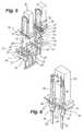
- FIG. 5is a perspective view of one embodiment of the disk scrubbing apparatus of the present invention.
- FIG. 6is a perspective view of a portion of the scrubbing apparatus shown in FIG. 5 , showing two pairs of disks positioned for scrubbing, although certain components have been removed, such as the scrubbing brushes, to better show the position of disks.
- FIG. 7is a front plan view of a lift saddle of the present invention.
- FIG. 8is a cross-section taken along line 8 - 8 of the lift saddle of FIG. 7 .
- FIG. 9is a perspective view of a pair of gap merge single-sided disks engaged by the upper demerge saddle of the present invention.
- FIG. 10is an end plan view of the apparatus shown in FIG. 9 , further showing a fluid delivery path and water nozzle.
- FIG. 11is a schematic side elevation view showing the scrubbing operation of the present invention.
- FIG. 12is an enlarged cross-sectional view of a pair of concentric contact merge disks just prior to demerging by the lower lift saddle.
- the preferred embodiment of the present apparatusprovides four stations 10 , 12 , 14 , 16 at which cassettes 18 containing a plurality of disks D are positioned.
- the cassettes 18have an open top and open bottom to allow pairs of disks to be removed from and returned to the cassettes 10 .
- a lift saddle 20is positioned below each cassette and is affixed to a shaft 22 .
- Each shaft 22moves the lift saddle 20 vertically between a lower position, beneath the cassettes, and an upper position, above the cassettes and within a scrubbing zone where the disk pairs are subjected to scrubbing and washing.
- the individual shaft 22may be interconnected, such as by plate 24 , to facilitate uniform movement of each lift saddle.
- the actions of multiple scrubbing zonescan be coordinated, and uniform efficient throughput achieved.
- the demerge saddles 26 and demerge shafts 28move vertically between a first position and a second position.
- the demerge shafts 28may also be interconnected by a plate or bracket 30 to facilitate uniform movement.
- the upper interconnector plate 30is attached to a servo actuator 32 which moves the demerge saddle 26 and demerge shafts 28 between the first and second positions.
- the lower interconnect plates 24are connected to similar actuators.
- the servo actuatorsprovide precise, uniform and coordinated movement of the saddles 20 and 26 . It should be appreciated that other means for moving the lifter saddle 20 and demerge saddle 26 , such as pneumatic or hydraulic systems, may be utilized as would be known by persons of skill in the art.
- the lifter saddle 20comprises a main body portion 34 attached to a shaft 22 .
- a cavity 36is formed in the body 34 of the lift saddle 20 to receive a shaft 22 .
- the lift saddle 20also includes a disk engagement portion 38 which engages the bottom perimeter edge of two disks.
- the engagement portion 38includes two curved grooves or channels 40 separated by a center tooth or wedge 42 .
- the center tooth or wedge 42may include multiple high pressure jet openings or nozzles 44 .
- the jet openingsare connected to a manifold or fluid delivery system 46 which delivers deionized water or other appropriate fluids to the nozzles 44 .
- a fluid source(not shown) is attached to the fluid delivery system 46 .
- Alternative fluidsinclude air or nitrogen.
- the grooves or channels 40 in the disk engagement portion 38 of the lift saddle 20are designed to maintain a pair of disks in gap merge orientation.
- Each channel 40is formed by the inside surface 48 of the saddle 20 side wall and by the side wall 50 of the center wedge. These two surfaces are formed at an angle that approximates the angle of the chamfer 52 on the outer perimeter edge of a disk.
- the flat base portion 54 of the channel 40approximates the width of the disk, less the chamfer portion.
- the disksmay be 95 millimeter in diameter and 0.050 inches thick, with a 45-degree chamfer. It should be appreciated that the present invention can be configured to work with a variety of disk sizes.
- cassettes 10are positioned at work station locations 10 , 12 , 14 , 16 . Additional work stations could be added or fewer could be employed.
- the cassettescontain a plurality of disks positioned in a single row, axially aligned. The disks are also preferably arranged in gap merge orientation ( FIG. 21 ).
- a gap merge orientation cassetteis described in co-pending U.S. patent application Ser. No. 10/435,362 entitled “Cassette Apparatus for Holding 25 Pairs of Disks for Manufacturing Process”, filed May 9, 2003, the entirety of which is incorporated herein by reference as if stated herein.
- the space or gap between the disks comprising a pairmay range from about 0.025 to 0.035 inches, with the preferable gap being about 0.035 inches.
- This gapallows a disk pair to utilize cleaning and scrubbing equipment originally designed and built to handle a single double-sided disk, without significant modifications.
- the cassettes 10are also positioned in an indexing mechanism, not shown, which moves or advances the cassette incrementally over the lift saddle 20 after a processed pair of disks is returned to the cassette such that the next pair of disks can be removed and processed.
- the demerge saddle 26includes a main body portion 56 and a disk engaging portion 58 .
- the disk engaging portion 58comprises a single groove or channel 60 formed by two angled side wall surfaces 62 and a flat bottom portion 64 .
- the demerge saddlealso includes a plurality of high pressure jets or nozzles 66 along the center of the flat portion 64 .
- the nozzles 66receive deionized water or other suitable liquid through a fluid delivery system 68 .
- the servo actuators 32move the demerge saddle 26 and lift saddle 20 into a position of engagement with a pair of disks in each cassette 10 .
- the lift saddle 20 and demerge saddle 26then move vertically upwardly, in unison, to remove the pair of disks from the cassette and move the pair to a disk scrubbing zone 70 .
- the pair of disksmay be transported to the scrubbing zone 70 solely by the lift saddle 20 .
- the demerge saddle 26may remain positioned above the scrubbing zone 70 and engage the disk pair following scrubbing for purposes of stabilizing and demerging the disks prior to the lift saddle returning the pair to the cassette.
- a fine mistmay be applied throughout the scrubbing zone in order to form a liquid layer on the L-side of each disk prior to changing the orientation of the disk pair into a contact merge orientation.
- the mistmay be continuously applied or intermittently applied as disk pairs move from the cassette to the scrubbing zone.
- the liquid layerassists in adhering the disks together so there is no relative movement between them.
- the upper outer perimeter edges of the disksare engaged by a pair of edge rollers 72 .
- the edge rollers 72have angled inside walls 74 and a flat base portion 76 .
- the edge rollers 72partially convert the orientation of the disk pair into a concentric contact merge orientation by forcing the top portion of the disks together.
- a pair of scrubbing brushes 78are positioned on each side of the disk pair, but initially spaced away from the disk pair in order that the upward movement of the disk pair is not impeded.
- a conventional 95 millimeter double-sided diskgenerally has a thickness of approximately 0.050 inches
- a single-sided disk of the same diametergenerally has a thickness of approximately 0.050 inches (or 0.10 inches for a pair).
- the pair of disksmust travel in a space created for a single double-sided disk. Therefore, the gap or space between the two single-sided disks must not be so large as to create an interference between the disks and the lift saddle on one hand, and the existing equipment on the other hand.
- An acceptable sized gapmay range between 0.025 inches and 0.035 inches for disks having a thickness of 0.050 inches. Therefore, the overall thickness of the disk pair is no greater than approximately 0.135 inches, which permits existing processing equipment to be used. It should be appreciated that the spacing between the disks may vary depending upon the thickness of the disks.
- the pair of rotating brushes 78are brought in contact with the outward facing surfaces (R-side) of each disk in each pair of disks. This opposed and inward movement of the brushes 78 fully removes the spacing between the disks, as the lift saddle 20 and demerge tool 26 simultaneously disengage the pair of disks.
- the brushes 78rotate upwardly, as shown in FIG. 11 , which forces the disks against the edge rollers 72 and secures the disks without the support of the lift saddle 20 .
- the brushesalso apply an inwardly directed force against the R-side surface of each disk.
- the inward pressure applied by the brushesis between 20 and 30 pounds per square inch, and preferably 25 pounds per square inch.
- the edge rollers 72are driven to impart rotation to the disk pair during scrubbing. In unison, the edge rollers 72 rotate the pair of disks and the brushes 78 rotate to scrub the rotating disks. Cleaning solution is applied to the disks in a manner known to those of skill in the art.
- the upward rotation of the brushes 78 against the disksmaintains the concentric contact merge orientation of the disks against the edge rollers 72 .
- the edge rollers 72also maintain the disks in a concentric merge orientation due to the profile of the walls 74 and base 76 .
- the angled walls 74correspond to the chamfer 52 of the outer edge of the disks and the width of the flat portion 76 corresponds to the thickness of the disk pair, less the chamfer portion 54 .
- the flat bottom portion 76also prevents lateral motion of one disk relative to the other.
- FIG. 11shows the lift saddle 20 and demerge saddle 26 removed from the scrubbing zone, such as during cleaning and scrubbing.
- FIG. 12shows the lift saddle 20 positioned proximate the disk pair just before the scrubbing brushes 78 release the disks and move away.
- the demerge saddle 26is similarly positioned proximate the upper perimeter edge of the disks.
- An important aspect of the transfer of disk support from the brushes 78 and edge rollers 72 to the lift saddle 20 and demerge saddle 26is that the outer perimeter of the disks be positioned within the channels 40 and 60 of the lift saddle and demerge saddle such that when the brushes 78 disengage the disks, the disks cannot be dropped. Rather, the disks are captured within the channels 40 and 60 .
- the disk pairis returned to a gap merge orientation. This is necessary in order that the lift saddle 20 can secure the pair of disks and return them to the cassette 18 , which is configured to receive disk pairs in a gap merge orientation.
- water jets 44 and 66are activated and directed at the interface 80 between the disks to force the disks apart.
- the jetswill create approximately a 0.005 inch gap between the disks.
- the demerge saddle 26may include a wedge to assist in mechanical separation of the disk pair.
- the servo actuators 32move the lift saddle 20 and demerge saddle 26 , together with gap merge disks, back to the cassette 18 .
- Each cassetteis then indexed to a new position to allow the process to be repeated with a new set of disk pairs.
- the demerge saddle 26may remain in place, or withdraw slightly, while the lift saddle 20 returns the disks to the cassette 18 .
- the dual servo actuator systems 32are programmable, accurate and offer simultaneous handling of disk pairs throughout the process.
- the scrubbing processis only a part of the overall cleaning of the disks or substrate disks. Also, cleaning may occur at one or more times during the overall manufacturing process. For example, cleaning may follow data zone texturing or laser zone texturing.
- the disksare initially subjected to a pre-soak in soapy water to loosen and remove organic materials and other particulates. While in the pre-soak, the liquid is subjected to ultrasound which turbulates the liquid and assists in removing unwanted particulate. The process is conducted while the disks are in cassettes. Next the disks, still within the cassettes, are subjected to a rinse of clean water. Scrubbing, as described above, typically follows the initial soak and rinse.
- the cassettes and disksproceed through a series of additional rinse steps and are then subjected to a drying cycle.
- the dryingis preferably performed in a spin dryer, with the disks still in the cassettes.
- the disksshould not be in a contact merge orientation, rather, at a minimum they should be in a gap merge orientation.
- placing the disk pairs in a gap merge orientationmay be efficient for processing purposes because the next process may preferably utilize disks in a gap merge orientation. Accordingly, placing the disks in a gap merge orientation following cleaning may not require reorienting the disks for the next process.
Landscapes
- Engineering & Computer Science (AREA)
- Manufacturing & Machinery (AREA)
- Manufacturing Of Magnetic Record Carriers (AREA)
Abstract
Description
- a) “R-side” and “L-side” refer to the active side and inactive side of a disk, respectively. R-side is the side that does or will have active recording materials and memory capability. The R-side may also be referred to as the active or functional side. The L-side is the side that has little or no active recording materials or memory capabilities; it is non-functional or inactive from a data storage stand point.
- b) “Merge” means to bring two disks closer together to form a pair of disks, a disk pair or a substrate pair.
- c) “Demerge,” conversely, means that a merged pair of disks is separated from each other.
- d) “Disk” means a finished memory disk and all predecessor configurations during the manufacturing process starting with a substrate disk and progressing to a finished memory disk, depending upon the context of the sentence in which it is used.
- e) “Disk pair” or “substrate pair” means two disks positioned in contact merge, gap merge or spacer merge orientation.
- f) “Double-sided disk” means a single disk which has been subjected to doublesided processing, whether or not both sides of the disk have passed testing or only one side has passed testing.
- g) “Gap merge” means a pair of disks that have been merged, but a space is maintained between the two merged disks. One or more spacers may or may not be used to maintain the gap or space. Gap merge includes both concentric and non-concentric merge. It should be understood that there is no precise dimension or limit to the space between the disks that causes them to be gap merged. Gap merge also includes the situation where the gap between the disks gradually decreases from one perimeter edge to the opposite perimeter edge of the disks when the two disks are angled toward each other. An example is when the bottom perimeter edges of the disks are spaced apart and the upper perimeter edges are in contact.
- h) “Single-sided disks” means a single disk which has been subjected to single-side processing, where only one surface of the disk is fully processed.
- i) “Spacer merge” means a spacer body is used to create spacing between two gap-merged disks.
- j) “Contact merge” means a merged pair of disks where the inside surface of each disk is in contact with the inside surface of the other disk. Contact merge includes concentric and non-concentric merge.
- k) “Concentric merge” means that two merged disks have the same axis and, assuming the two disks have the same outside diameter and inside diameter (as defined by the center aperture), their outer and inner perimeter edges are aligned.
- l) “Concentric contact merge” means a pair of disks that are oriented in both a contact merge and a concentric merge.
- m) “Non-concentric merge” or “off-centered merge” means the two merged disks are not concentric to each other or their perimeter edges are not aligned.
- n) “Non-concentric contact merge” means the two contact merged disks are not concentric to each other or their perimeter edges are not aligned.
Claims (32)
Priority Applications (1)
| Application Number | Priority Date | Filing Date | Title |
|---|---|---|---|
| US10/435,293US8172954B2 (en) | 2002-10-10 | 2003-05-09 | Apparatus for simultaneous two-disk scrubbing and washing |
Applications Claiming Priority (3)
| Application Number | Priority Date | Filing Date | Title |
|---|---|---|---|
| US41743202P | 2002-10-10 | 2002-10-10 | |
| US42561402P | 2002-11-11 | 2002-11-11 | |
| US10/435,293US8172954B2 (en) | 2002-10-10 | 2003-05-09 | Apparatus for simultaneous two-disk scrubbing and washing |
Publications (2)
| Publication Number | Publication Date |
|---|---|
| US20040070859A1 US20040070859A1 (en) | 2004-04-15 |
| US8172954B2true US8172954B2 (en) | 2012-05-08 |
Family
ID=32074381
Family Applications (1)
| Application Number | Title | Priority Date | Filing Date |
|---|---|---|---|
| US10/435,293Expired - Fee RelatedUS8172954B2 (en) | 2002-10-10 | 2003-05-09 | Apparatus for simultaneous two-disk scrubbing and washing |
Country Status (1)
| Country | Link |
|---|---|
| US (1) | US8172954B2 (en) |
Families Citing this family (17)
| Publication number | Priority date | Publication date | Assignee | Title |
|---|---|---|---|---|
| US7027246B2 (en)* | 2002-05-09 | 2006-04-11 | Maxtor Corporation | Method for servo pattern application on single-side processed disks in a merged state |
| TWI229324B (en)* | 2002-05-09 | 2005-03-11 | Maxtor Corp | Method of simultaneous two-disk processing of single-sided magnetic recording disks |
| US7180709B2 (en)* | 2002-05-09 | 2007-02-20 | Maxtor Corporation | Information-storage media with dissimilar outer diameter and/or inner diameter chamfer designs on two sides |
| US7600359B2 (en) | 2002-05-09 | 2009-10-13 | Seagate Technology Llc | Method of merging two disks concentrically without gap between disks |
| US7052739B2 (en)* | 2002-05-09 | 2006-05-30 | Maxtor Corporation | Method of lubricating multiple magnetic storage disks in close proximity |
| US7083871B2 (en) | 2002-05-09 | 2006-08-01 | Maxtor Corporation | Single-sided sputtered magnetic recording disks |
| US7628895B2 (en)* | 2002-05-09 | 2009-12-08 | Seagate Technology Llc | W-patterned tools for transporting/handling pairs of disks |
| US7165308B2 (en)* | 2002-05-09 | 2007-01-23 | Maxtor Corporation | Dual disk transport mechanism processing two disks tilted toward each other |
| US7367773B2 (en)* | 2002-05-09 | 2008-05-06 | Maxtor Corporation | Apparatus for combining or separating disk pairs simultaneously |
| US7083376B2 (en)* | 2002-10-10 | 2006-08-01 | Maxtor Corporation | Automated merge nest for pairs of magnetic storage disks |
| US7083502B2 (en)* | 2002-10-10 | 2006-08-01 | Maxtor Corporation | Method for simultaneous two-disk texturing |
| US7748532B2 (en)* | 2002-10-10 | 2010-07-06 | Seagate Technology Llc | Cassette for holding disks of different diameters |
| US7168153B2 (en)* | 2002-10-10 | 2007-01-30 | Maxtor Corporation | Method for manufacturing single-sided hard memory disks |
| US7682653B1 (en)* | 2004-06-17 | 2010-03-23 | Seagate Technology Llc | Magnetic disk with uniform lubricant thickness distribution |
| JP2006031760A (en)* | 2004-07-13 | 2006-02-02 | Sony Corp | Manufacturing method of magnetic disk device, test equipment for magnetic disk device, and test method for the test equipment |
| US7882616B1 (en) | 2004-09-02 | 2011-02-08 | Seagate Technology Llc | Manufacturing single-sided storage media |
| JP2010257562A (en)* | 2009-03-30 | 2010-11-11 | Hoya Corp | Substrate for magnetic disk and method for manufacturing the same |
Citations (72)
| Publication number | Priority date | Publication date | Assignee | Title |
|---|---|---|---|---|
| US3382647A (en) | 1965-05-20 | 1968-05-14 | Deering Milliken Inc | Coin wrapping machine |
| US3505777A (en) | 1967-06-01 | 1970-04-14 | Maui Pineapple Co Ltd | Can loader |
| US4573851A (en) | 1983-05-18 | 1986-03-04 | Microglass, Inc. | Semiconductor wafer transfer apparatus and method |
| EP0177073A2 (en) | 1984-08-21 | 1986-04-09 | Komag, Inc. | Disk carrier and plug |
| EP0192244A1 (en) | 1985-02-18 | 1986-08-27 | Hitachi Maxell Ltd. | An optical disc |
| US4676008A (en) | 1986-05-16 | 1987-06-30 | Microglass, Inc. | Cage-type wafer carrier and method |
| US4694778A (en) | 1984-05-04 | 1987-09-22 | Anicon, Inc. | Chemical vapor deposition wafer boat |
| US4695217A (en) | 1983-11-21 | 1987-09-22 | Lau John J | Semiconductor wafer transfer apparatus |
| US4768328A (en) | 1987-01-13 | 1988-09-06 | Machine Builders And Design | Automatic tray packer |
| US4819579A (en) | 1981-01-14 | 1989-04-11 | Northern Telecom Limited | Coating of semiconductor wafers and apparatus therefor |
| US4840530A (en) | 1988-05-23 | 1989-06-20 | Nguyen Loc H | Transfer apparatus for semiconductor wafers |
| US4856957A (en) | 1988-01-11 | 1989-08-15 | Mactronix, Inc. | Semiconductor wafer transfer apparatus with back-to-back positioning and separation |
| US4947784A (en) | 1987-12-07 | 1990-08-14 | Tel Sagami Limited | Apparatus and method for transferring wafers between a cassette and a boat |
| US4947624A (en) | 1989-05-08 | 1990-08-14 | Planet Products Corporation | Article processing machine and method of making same |
| US4958982A (en) | 1988-02-26 | 1990-09-25 | Centre Stephanois De Recherches Mecaniques Hydromecanique Et Frottement | Device for transferring items |
| US4962879A (en) | 1988-12-19 | 1990-10-16 | Duke University | Method for bubble-free bonding of silicon wafers |
| US4981222A (en) | 1988-08-24 | 1991-01-01 | Asq Boats, Inc. | Wafer boat |
| US4987407A (en) | 1988-04-22 | 1991-01-22 | Asq. Boats, Inc. | Wafer interleaving with electro-optical safety features |
| US5007788A (en) | 1988-04-25 | 1991-04-16 | Tel Sagami Limited | Pitch changing device for changing pitches of plate-like objects and method of changing pitches |
| US5111936A (en) | 1990-11-30 | 1992-05-12 | Fluoroware | Wafer carrier |
| US5125784A (en) | 1988-03-11 | 1992-06-30 | Tel Sagami Limited | Wafers transfer device |
| US5188499A (en) | 1990-12-14 | 1993-02-23 | Mactronix | Method and apparatus for varying wafer spacing |
| US5203360A (en)* | 1990-12-17 | 1993-04-20 | Seagate Technology, Inc. | Disc washing system |
| US5269643A (en) | 1991-03-22 | 1993-12-14 | Danippon Screen Manufacturing Co., Ltd. | Method and apparatus for transferring wafers from wafer carrier to wafer conveyor apparatus in carrierless wafer surface treatment apparatus |
| US5314107A (en) | 1992-12-31 | 1994-05-24 | Motorola, Inc. | Automated method for joining wafers |
| US5430992A (en) | 1993-09-20 | 1995-07-11 | Riverwood International Corporation | Stacked article carrier packaging |
| JPH07263521A (en) | 1994-03-18 | 1995-10-13 | Fujitsu Ltd | Wafer transfer apparatus and method and semiconductor device manufacturing method |
| US5486134A (en) | 1992-02-27 | 1996-01-23 | Oliver Design, Inc. | System and method for texturing magnetic data storage disks |
| US5501568A (en) | 1993-07-01 | 1996-03-26 | Mitsubishi Denki Kabushiki Kaisha | Wafer aligning apparatus |
| JPH08273210A (en) | 1995-03-30 | 1996-10-18 | Toshiba Emi Ltd | Method and apparatus for manufacturing bonded disc |
| US5620295A (en) | 1990-11-17 | 1997-04-15 | Tokyo Electron Limited | Transfer apparatus |
| EP0768704A2 (en) | 1995-10-13 | 1997-04-16 | Tokyo Electron Limited | A substrate cleaning method and a substrate cleaning apparatus |
| US5664407A (en) | 1993-05-14 | 1997-09-09 | Cooper, Iii; Clayton C. | Packaging machine |
| WO1998036867A1 (en) | 1997-02-10 | 1998-08-27 | Laserway Inc. | Method and apparatus for laser texturing a magnetic recording disk substrate |
| US5820449A (en) | 1995-06-07 | 1998-10-13 | Clover; Richmond B. | Vertically stacked planarization machine |
| US5906469A (en) | 1995-11-22 | 1999-05-25 | Dainippon Screen Mfg. Co., Ltd. | Apparatus and method for detecting and conveying substrates in cassette |
| US5956317A (en) | 1995-07-28 | 1999-09-21 | Toshiba-Emi Limited | Composite optical disk with structure for preventing adhesive from leaking into the center hole |
| US5976255A (en) | 1997-09-20 | 1999-11-02 | Anelva Corporation | Substrate holder for reducing non-uniform film characteristics resulting from support structures |
| US5991104A (en)* | 1996-11-27 | 1999-11-23 | Seagate Technology, Inc. | Using servowriter medium for quickly written servo-patterns on magnetic media |
| US6022837A (en) | 1996-11-26 | 2000-02-08 | Fujimi Incorporated | Method for rinsing a polished memory hard disk |
| US6033486A (en)* | 1996-07-09 | 2000-03-07 | Andros; Nicholas | Method for cleaning a surface by using a cationic sponge material |
| US6033522A (en) | 1997-07-08 | 2000-03-07 | System Seiko Co., Ltd. | Surface treatment method and apparatus for rotatable disc |
| US6086961A (en)* | 1998-03-09 | 2000-07-11 | Seagate Technology, Inc. | Quickly written servo-patterns for magnetic media including removing |
| US6107599A (en) | 1997-02-06 | 2000-08-22 | International Business Machines Corporation | Method and tool for laser texturing of glass substrates |
| US6182814B1 (en) | 2000-03-03 | 2001-02-06 | Sig Pack, Inc., Doboy Division | Inline vacuum slug feeder |
| US6230891B1 (en) | 1998-06-22 | 2001-05-15 | Sakurai Co., Ltd. | Container and supporting member for memory disks |
| JP2001232667A (en) | 1999-12-29 | 2001-08-28 | Imation Corp | Mold for manufacturing double-sided disk-shaped articles for data storage |
| US20020006324A1 (en) | 1998-11-03 | 2002-01-17 | Michito Sato | Apparatus and method for automatically transferring wafers between wafer holders in a liquid environment |
| US6345947B1 (en) | 1997-11-10 | 2002-02-12 | Tokyo Electron Limited | Substrate arranging apparatus and method |
| US6368040B1 (en) | 1998-02-18 | 2002-04-09 | Tokyo Electron Limited | Apparatus for and method of transporting substrates to be processed |
| US20020100132A1 (en) | 2001-01-30 | 2002-08-01 | Mcmullen Daniel T. | Porous polymeric substrate treatment device and method |
| US6427850B2 (en) | 1998-02-04 | 2002-08-06 | Micron Technology, Inc. | Electronic device workpiece carriers |
| US6438781B1 (en)* | 2000-04-21 | 2002-08-27 | Toda Citron Technologies, Inc. | Washer for cleaning substrates |
| US6582279B1 (en) | 2002-03-07 | 2003-06-24 | Hitachi Global Storage Technologies Netherlands B.V. | Apparatus and method for reclaiming a disk substrate for use in a data storage device |
| US6612801B1 (en) | 1999-08-26 | 2003-09-02 | Tokyo Electron Limited | Method and device for arraying substrates and processing apparatus thereof |
| US6626744B1 (en) | 1999-12-17 | 2003-09-30 | Applied Materials, Inc. | Planarization system with multiple polishing pads |
| US6625835B1 (en) | 1999-05-27 | 2003-09-30 | Lam Research Corporation | Disk cascade scrubber |
| US20030211275A1 (en) | 2002-05-09 | 2003-11-13 | Gerardo Buitron | Method of simultaneous two-disk processing of single-sided magnetic recording disks |
| US20030208899A1 (en) | 2002-05-09 | 2003-11-13 | John Grow | Dual disk transport mechanism processing two disks tilted toward each other |
| US20030211361A1 (en) | 2002-05-09 | 2003-11-13 | Kim Kwang Kon | Single-sided sputtered magnetic recording disks |
| US20030209389A1 (en) | 2002-05-09 | 2003-11-13 | Gerardo Buitron | Method of lubricating multiple magnetic storage disks in close proximity |
| US20030209421A1 (en) | 2002-05-09 | 2003-11-13 | Gerardo Buitron | W-patterned tools for transporting/handling pairs of disks |
| US20030210498A1 (en) | 2002-05-09 | 2003-11-13 | Kim Kwang Kon | Information-storage media with dissimilar outer diameter and/or inner diameter chamfer designs on two sides |
| US20040013011A1 (en) | 2002-05-09 | 2004-01-22 | Valeri Thomas M | Method for servo pattern application on single-side processed disks in a merged state |
| US20040016214A1 (en) | 2002-05-09 | 2004-01-29 | Gerardo Buitron | Method of merging two disks concentrically without gap between disks |
| US20040035737A1 (en) | 2002-05-09 | 2004-02-26 | Gerardo Buitron | Apparatus for combining or separating disk pairs simultaneously |
| US20040069662A1 (en) | 2002-10-10 | 2004-04-15 | Gerardo Buitron | Cassette for holding disks of multiple form factors |
| US20040070092A1 (en) | 2002-10-10 | 2004-04-15 | Gerardo Buitron | Method for simultaneous two-disk texturing |
| US20040071535A1 (en) | 2002-10-10 | 2004-04-15 | Walter Crofton | Automated merge nest for pairs of magnetic storage disks |
| US20040068862A1 (en) | 2002-10-10 | 2004-04-15 | Gerardo Buitron | Cassette apparatus for holding 25 pairs of disks for manufacturing process |
| US6769855B2 (en) | 2000-12-27 | 2004-08-03 | Tokyo Electron Limited | Substrate processing apparatus and substrate processing method |
| US6821189B1 (en) | 2000-10-13 | 2004-11-23 | 3M Innovative Properties Company | Abrasive article comprising a structured diamond-like carbon coating and method of using same to mechanically treat a substrate |
- 2003
- 2003-05-09USUS10/435,293patent/US8172954B2/ennot_activeExpired - Fee Related
Patent Citations (75)
| Publication number | Priority date | Publication date | Assignee | Title |
|---|---|---|---|---|
| US3382647A (en) | 1965-05-20 | 1968-05-14 | Deering Milliken Inc | Coin wrapping machine |
| US3505777A (en) | 1967-06-01 | 1970-04-14 | Maui Pineapple Co Ltd | Can loader |
| US4819579A (en) | 1981-01-14 | 1989-04-11 | Northern Telecom Limited | Coating of semiconductor wafers and apparatus therefor |
| US4573851A (en) | 1983-05-18 | 1986-03-04 | Microglass, Inc. | Semiconductor wafer transfer apparatus and method |
| US4695217A (en) | 1983-11-21 | 1987-09-22 | Lau John J | Semiconductor wafer transfer apparatus |
| US4694778A (en) | 1984-05-04 | 1987-09-22 | Anicon, Inc. | Chemical vapor deposition wafer boat |
| EP0177073A2 (en) | 1984-08-21 | 1986-04-09 | Komag, Inc. | Disk carrier and plug |
| EP0192244A1 (en) | 1985-02-18 | 1986-08-27 | Hitachi Maxell Ltd. | An optical disc |
| US4676008A (en) | 1986-05-16 | 1987-06-30 | Microglass, Inc. | Cage-type wafer carrier and method |
| US4768328A (en) | 1987-01-13 | 1988-09-06 | Machine Builders And Design | Automatic tray packer |
| US4947784A (en) | 1987-12-07 | 1990-08-14 | Tel Sagami Limited | Apparatus and method for transferring wafers between a cassette and a boat |
| US4856957A (en) | 1988-01-11 | 1989-08-15 | Mactronix, Inc. | Semiconductor wafer transfer apparatus with back-to-back positioning and separation |
| US4958982A (en) | 1988-02-26 | 1990-09-25 | Centre Stephanois De Recherches Mecaniques Hydromecanique Et Frottement | Device for transferring items |
| US5125784A (en) | 1988-03-11 | 1992-06-30 | Tel Sagami Limited | Wafers transfer device |
| US4987407A (en) | 1988-04-22 | 1991-01-22 | Asq. Boats, Inc. | Wafer interleaving with electro-optical safety features |
| US5007788A (en) | 1988-04-25 | 1991-04-16 | Tel Sagami Limited | Pitch changing device for changing pitches of plate-like objects and method of changing pitches |
| US4840530A (en) | 1988-05-23 | 1989-06-20 | Nguyen Loc H | Transfer apparatus for semiconductor wafers |
| US4981222A (en) | 1988-08-24 | 1991-01-01 | Asq Boats, Inc. | Wafer boat |
| US4962879A (en) | 1988-12-19 | 1990-10-16 | Duke University | Method for bubble-free bonding of silicon wafers |
| US4947624A (en) | 1989-05-08 | 1990-08-14 | Planet Products Corporation | Article processing machine and method of making same |
| US5620295A (en) | 1990-11-17 | 1997-04-15 | Tokyo Electron Limited | Transfer apparatus |
| US5111936A (en) | 1990-11-30 | 1992-05-12 | Fluoroware | Wafer carrier |
| US5188499A (en) | 1990-12-14 | 1993-02-23 | Mactronix | Method and apparatus for varying wafer spacing |
| US5203360A (en)* | 1990-12-17 | 1993-04-20 | Seagate Technology, Inc. | Disc washing system |
| US5269643A (en) | 1991-03-22 | 1993-12-14 | Danippon Screen Manufacturing Co., Ltd. | Method and apparatus for transferring wafers from wafer carrier to wafer conveyor apparatus in carrierless wafer surface treatment apparatus |
| US5486134A (en) | 1992-02-27 | 1996-01-23 | Oliver Design, Inc. | System and method for texturing magnetic data storage disks |
| US5314107A (en) | 1992-12-31 | 1994-05-24 | Motorola, Inc. | Automated method for joining wafers |
| US5664407A (en) | 1993-05-14 | 1997-09-09 | Cooper, Iii; Clayton C. | Packaging machine |
| US5501568A (en) | 1993-07-01 | 1996-03-26 | Mitsubishi Denki Kabushiki Kaisha | Wafer aligning apparatus |
| US5430992A (en) | 1993-09-20 | 1995-07-11 | Riverwood International Corporation | Stacked article carrier packaging |
| JPH07263521A (en) | 1994-03-18 | 1995-10-13 | Fujitsu Ltd | Wafer transfer apparatus and method and semiconductor device manufacturing method |
| JPH08273210A (en) | 1995-03-30 | 1996-10-18 | Toshiba Emi Ltd | Method and apparatus for manufacturing bonded disc |
| US5820449A (en) | 1995-06-07 | 1998-10-13 | Clover; Richmond B. | Vertically stacked planarization machine |
| US5956317A (en) | 1995-07-28 | 1999-09-21 | Toshiba-Emi Limited | Composite optical disk with structure for preventing adhesive from leaking into the center hole |
| EP0768704A2 (en) | 1995-10-13 | 1997-04-16 | Tokyo Electron Limited | A substrate cleaning method and a substrate cleaning apparatus |
| US5906469A (en) | 1995-11-22 | 1999-05-25 | Dainippon Screen Mfg. Co., Ltd. | Apparatus and method for detecting and conveying substrates in cassette |
| US6033486A (en)* | 1996-07-09 | 2000-03-07 | Andros; Nicholas | Method for cleaning a surface by using a cationic sponge material |
| US6022837A (en) | 1996-11-26 | 2000-02-08 | Fujimi Incorporated | Method for rinsing a polished memory hard disk |
| US5991104A (en)* | 1996-11-27 | 1999-11-23 | Seagate Technology, Inc. | Using servowriter medium for quickly written servo-patterns on magnetic media |
| US6107599A (en) | 1997-02-06 | 2000-08-22 | International Business Machines Corporation | Method and tool for laser texturing of glass substrates |
| WO1998036867A1 (en) | 1997-02-10 | 1998-08-27 | Laserway Inc. | Method and apparatus for laser texturing a magnetic recording disk substrate |
| US6033522A (en) | 1997-07-08 | 2000-03-07 | System Seiko Co., Ltd. | Surface treatment method and apparatus for rotatable disc |
| US5976255A (en) | 1997-09-20 | 1999-11-02 | Anelva Corporation | Substrate holder for reducing non-uniform film characteristics resulting from support structures |
| US6345947B1 (en) | 1997-11-10 | 2002-02-12 | Tokyo Electron Limited | Substrate arranging apparatus and method |
| US6427850B2 (en) | 1998-02-04 | 2002-08-06 | Micron Technology, Inc. | Electronic device workpiece carriers |
| US6368040B1 (en) | 1998-02-18 | 2002-04-09 | Tokyo Electron Limited | Apparatus for and method of transporting substrates to be processed |
| US6086961A (en)* | 1998-03-09 | 2000-07-11 | Seagate Technology, Inc. | Quickly written servo-patterns for magnetic media including removing |
| US6230891B1 (en) | 1998-06-22 | 2001-05-15 | Sakurai Co., Ltd. | Container and supporting member for memory disks |
| US6457929B2 (en) | 1998-11-03 | 2002-10-01 | Seh America, Inc. | Apparatus and method for automatically transferring wafers between wafer holders in a liquid environment |
| US6354794B2 (en) | 1998-11-03 | 2002-03-12 | Seh America, Inc. | Method for automatically transferring wafers between wafer holders in a liquid environment |
| US20020006324A1 (en) | 1998-11-03 | 2002-01-17 | Michito Sato | Apparatus and method for automatically transferring wafers between wafer holders in a liquid environment |
| US6625835B1 (en) | 1999-05-27 | 2003-09-30 | Lam Research Corporation | Disk cascade scrubber |
| US6612801B1 (en) | 1999-08-26 | 2003-09-02 | Tokyo Electron Limited | Method and device for arraying substrates and processing apparatus thereof |
| US6626744B1 (en) | 1999-12-17 | 2003-09-30 | Applied Materials, Inc. | Planarization system with multiple polishing pads |
| JP2001232667A (en) | 1999-12-29 | 2001-08-28 | Imation Corp | Mold for manufacturing double-sided disk-shaped articles for data storage |
| US6182814B1 (en) | 2000-03-03 | 2001-02-06 | Sig Pack, Inc., Doboy Division | Inline vacuum slug feeder |
| US6438781B1 (en)* | 2000-04-21 | 2002-08-27 | Toda Citron Technologies, Inc. | Washer for cleaning substrates |
| US6821189B1 (en) | 2000-10-13 | 2004-11-23 | 3M Innovative Properties Company | Abrasive article comprising a structured diamond-like carbon coating and method of using same to mechanically treat a substrate |
| US6769855B2 (en) | 2000-12-27 | 2004-08-03 | Tokyo Electron Limited | Substrate processing apparatus and substrate processing method |
| US20020100132A1 (en) | 2001-01-30 | 2002-08-01 | Mcmullen Daniel T. | Porous polymeric substrate treatment device and method |
| US6582279B1 (en) | 2002-03-07 | 2003-06-24 | Hitachi Global Storage Technologies Netherlands B.V. | Apparatus and method for reclaiming a disk substrate for use in a data storage device |
| US20030211361A1 (en) | 2002-05-09 | 2003-11-13 | Kim Kwang Kon | Single-sided sputtered magnetic recording disks |
| US20030208899A1 (en) | 2002-05-09 | 2003-11-13 | John Grow | Dual disk transport mechanism processing two disks tilted toward each other |
| US20030209421A1 (en) | 2002-05-09 | 2003-11-13 | Gerardo Buitron | W-patterned tools for transporting/handling pairs of disks |
| US20030210498A1 (en) | 2002-05-09 | 2003-11-13 | Kim Kwang Kon | Information-storage media with dissimilar outer diameter and/or inner diameter chamfer designs on two sides |
| US20040013011A1 (en) | 2002-05-09 | 2004-01-22 | Valeri Thomas M | Method for servo pattern application on single-side processed disks in a merged state |
| US20040016214A1 (en) | 2002-05-09 | 2004-01-29 | Gerardo Buitron | Method of merging two disks concentrically without gap between disks |
| US20040035737A1 (en) | 2002-05-09 | 2004-02-26 | Gerardo Buitron | Apparatus for combining or separating disk pairs simultaneously |
| US20030209389A1 (en) | 2002-05-09 | 2003-11-13 | Gerardo Buitron | Method of lubricating multiple magnetic storage disks in close proximity |
| US7322098B2 (en)* | 2002-05-09 | 2008-01-29 | Maxtor Corporation | Method of simultaneous two-disk processing of single-sided magnetic recording disks |
| US20030211275A1 (en) | 2002-05-09 | 2003-11-13 | Gerardo Buitron | Method of simultaneous two-disk processing of single-sided magnetic recording disks |
| US20040069662A1 (en) | 2002-10-10 | 2004-04-15 | Gerardo Buitron | Cassette for holding disks of multiple form factors |
| US20040068862A1 (en) | 2002-10-10 | 2004-04-15 | Gerardo Buitron | Cassette apparatus for holding 25 pairs of disks for manufacturing process |
| US20040071535A1 (en) | 2002-10-10 | 2004-04-15 | Walter Crofton | Automated merge nest for pairs of magnetic storage disks |
| US20040070092A1 (en) | 2002-10-10 | 2004-04-15 | Gerardo Buitron | Method for simultaneous two-disk texturing |
Non-Patent Citations (3)
| Title |
|---|
| "Design of an active memory system for network applications"; Asthana, A.; Cravatts, M.; Krzyzanowski, P.; Memory Technology, Design and Testing, Aug. 8-9, 1994; p. 58-63. |
| Australian Written Opinion and Search Report, Dec. 17, 2004, Singapore Application No. SG200302857-8. |
| Mar. 12, 2005 Invitiation to Respond to Written Opinion from Intellectual Property Office of Singapore to Tan Jinhwee, Eunice & Lim Chooeng. |
Also Published As
| Publication number | Publication date |
|---|---|
| US20040070859A1 (en) | 2004-04-15 |
Similar Documents
| Publication | Publication Date | Title |
|---|---|---|
| US8172954B2 (en) | Apparatus for simultaneous two-disk scrubbing and washing | |
| US7789615B2 (en) | Apparatus for combining or separating disk pairs simultaneously | |
| US7322098B2 (en) | Method of simultaneous two-disk processing of single-sided magnetic recording disks | |
| US7083376B2 (en) | Automated merge nest for pairs of magnetic storage disks | |
| US20060115599A1 (en) | Method of lubricating multiple magnetic storage disks in close proximity | |
| US6588043B1 (en) | Wafer cascade scrubber | |
| US7168153B2 (en) | Method for manufacturing single-sided hard memory disks | |
| US7600359B2 (en) | Method of merging two disks concentrically without gap between disks | |
| US7083502B2 (en) | Method for simultaneous two-disk texturing | |
| CN216298969U (en) | Modular Polishing System | |
| US7628895B2 (en) | W-patterned tools for transporting/handling pairs of disks | |
| US6910240B1 (en) | Wafer bevel edge cleaning system and apparatus | |
| US7748532B2 (en) | Cassette for holding disks of different diameters | |
| US7165308B2 (en) | Dual disk transport mechanism processing two disks tilted toward each other | |
| US7027246B2 (en) | Method for servo pattern application on single-side processed disks in a merged state | |
| JP2011527947A (en) | Integrated circuit cutting apparatus and method | |
| CN115863227A (en) | Wafer fine cleaning tool and using method thereof | |
| US20120111360A1 (en) | Method and Apparatus for Cleaning a Substrate | |
| KR20230027484A (en) | High throughput polishing modules and modular polishing systems | |
| US9406325B2 (en) | Slider cleaning and carrier tray | |
| WO2013125938A1 (en) | An apparatus for cleaning a substrate | |
| US6011618A (en) | Method and apparatus of surface inspection of a disk | |
| JPH05242534A (en) | Method and device for cleaning peripheral cylindrical face of disk for producing disk type information recording medium | |
| JP2006332386A (en) | Substrate cleaning apparatus and substrate cleaning method | |
| JP2789877B2 (en) | Disk polishing machine |
Legal Events
| Date | Code | Title | Description |
|---|---|---|---|
| AS | Assignment | Owner name:MAXTOR CORPORATION, COLORADO Free format text:ASSIGNMENT OF ASSIGNORS INTEREST;ASSIGNORS:CROFTON, WALTER;WYPYCH, ANDREW;REEL/FRAME:014064/0724 Effective date:20030507 | |
| AS | Assignment | Owner name:WELLS FARGO BANK, NATIONAL ASSOCIATION, AS COLLATERAL AGENT AND SECOND PRIORITY REPRESENTATIVE, CALIFORNIA Free format text:SECURITY AGREEMENT;ASSIGNORS:MAXTOR CORPORATION;SEAGATE TECHNOLOGY LLC;SEAGATE TECHNOLOGY INTERNATIONAL;REEL/FRAME:022757/0017 Effective date:20090507 Owner name:JPMORGAN CHASE BANK, N.A., AS ADMINISTRATIVE AGENT AND FIRST PRIORITY REPRESENTATIVE, NEW YORK Free format text:SECURITY AGREEMENT;ASSIGNORS:MAXTOR CORPORATION;SEAGATE TECHNOLOGY LLC;SEAGATE TECHNOLOGY INTERNATIONAL;REEL/FRAME:022757/0017 Effective date:20090507 Owner name:JPMORGAN CHASE BANK, N.A., AS ADMINISTRATIVE AGENT Free format text:SECURITY AGREEMENT;ASSIGNORS:MAXTOR CORPORATION;SEAGATE TECHNOLOGY LLC;SEAGATE TECHNOLOGY INTERNATIONAL;REEL/FRAME:022757/0017 Effective date:20090507 Owner name:WELLS FARGO BANK, NATIONAL ASSOCIATION, AS COLLATE Free format text:SECURITY AGREEMENT;ASSIGNORS:MAXTOR CORPORATION;SEAGATE TECHNOLOGY LLC;SEAGATE TECHNOLOGY INTERNATIONAL;REEL/FRAME:022757/0017 Effective date:20090507 | |
| AS | Assignment | Owner name:SEAGATE TECHNOLOGY LLC, CALIFORNIA Free format text:ASSIGNMENT OF ASSIGNORS INTEREST;ASSIGNOR:MAXTOR CORPORATION;REEL/FRAME:022987/0909 Effective date:20090529 Owner name:SEAGATE TECHNOLOGY LLC,CALIFORNIA Free format text:ASSIGNMENT OF ASSIGNORS INTEREST;ASSIGNOR:MAXTOR CORPORATION;REEL/FRAME:022987/0909 Effective date:20090529 | |
| AS | Assignment | Owner name:SEAGATE TECHNOLOGY LLC, CALIFORNIA Free format text:RELEASE;ASSIGNOR:JPMORGAN CHASE BANK, N.A., AS ADMINISTRATIVE AGENT;REEL/FRAME:025662/0001 Effective date:20110114 Owner name:MAXTOR CORPORATION, CALIFORNIA Free format text:RELEASE;ASSIGNOR:JPMORGAN CHASE BANK, N.A., AS ADMINISTRATIVE AGENT;REEL/FRAME:025662/0001 Effective date:20110114 Owner name:SEAGATE TECHNOLOGY HDD HOLDINGS, CALIFORNIA Free format text:RELEASE;ASSIGNOR:JPMORGAN CHASE BANK, N.A., AS ADMINISTRATIVE AGENT;REEL/FRAME:025662/0001 Effective date:20110114 Owner name:SEAGATE TECHNOLOGY INTERNATIONAL, CALIFORNIA Free format text:RELEASE;ASSIGNOR:JPMORGAN CHASE BANK, N.A., AS ADMINISTRATIVE AGENT;REEL/FRAME:025662/0001 Effective date:20110114 | |
| AS | Assignment | Owner name:THE BANK OF NOVA SCOTIA, AS ADMINISTRATIVE AGENT, CANADA Free format text:SECURITY AGREEMENT;ASSIGNOR:SEAGATE TECHNOLOGY LLC;REEL/FRAME:026010/0350 Effective date:20110118 Owner name:THE BANK OF NOVA SCOTIA, AS ADMINISTRATIVE AGENT, Free format text:SECURITY AGREEMENT;ASSIGNOR:SEAGATE TECHNOLOGY LLC;REEL/FRAME:026010/0350 Effective date:20110118 | |
| AS | Assignment | Owner name:SEAGATE TECHNOLOGY INTERNATIONAL, CAYMAN ISLANDS Free format text:TERMINATION AND RELEASE OF SECURITY INTEREST IN PATENT RIGHTS;ASSIGNOR:WELLS FARGO BANK, NATIONAL ASSOCIATION, AS COLLATERAL AGENT AND SECOND PRIORITY REPRESENTATIVE;REEL/FRAME:030833/0001 Effective date:20130312 Owner name:SEAGATE TECHNOLOGY US HOLDINGS, INC., CALIFORNIA Free format text:TERMINATION AND RELEASE OF SECURITY INTEREST IN PATENT RIGHTS;ASSIGNOR:WELLS FARGO BANK, NATIONAL ASSOCIATION, AS COLLATERAL AGENT AND SECOND PRIORITY REPRESENTATIVE;REEL/FRAME:030833/0001 Effective date:20130312 Owner name:SEAGATE TECHNOLOGY LLC, CALIFORNIA Free format text:TERMINATION AND RELEASE OF SECURITY INTEREST IN PATENT RIGHTS;ASSIGNOR:WELLS FARGO BANK, NATIONAL ASSOCIATION, AS COLLATERAL AGENT AND SECOND PRIORITY REPRESENTATIVE;REEL/FRAME:030833/0001 Effective date:20130312 Owner name:EVAULT INC. (F/K/A I365 INC.), CALIFORNIA Free format text:TERMINATION AND RELEASE OF SECURITY INTEREST IN PATENT RIGHTS;ASSIGNOR:WELLS FARGO BANK, NATIONAL ASSOCIATION, AS COLLATERAL AGENT AND SECOND PRIORITY REPRESENTATIVE;REEL/FRAME:030833/0001 Effective date:20130312 | |
| REMI | Maintenance fee reminder mailed | ||
| LAPS | Lapse for failure to pay maintenance fees | ||
| STCH | Information on status: patent discontinuation | Free format text:PATENT EXPIRED DUE TO NONPAYMENT OF MAINTENANCE FEES UNDER 37 CFR 1.362 | |
| FP | Lapsed due to failure to pay maintenance fee | Effective date:20160508 | |
| AS | Assignment | Owner name:SEAGATE TECHNOLOGY PUBLIC LIMITED COMPANY, CALIFORNIA Free format text:RELEASE BY SECURED PARTY;ASSIGNOR:THE BANK OF NOVA SCOTIA;REEL/FRAME:072193/0001 Effective date:20250303 Owner name:SEAGATE TECHNOLOGY, CALIFORNIA Free format text:RELEASE BY SECURED PARTY;ASSIGNOR:THE BANK OF NOVA SCOTIA;REEL/FRAME:072193/0001 Effective date:20250303 Owner name:SEAGATE TECHNOLOGY HDD HOLDINGS, CALIFORNIA Free format text:RELEASE BY SECURED PARTY;ASSIGNOR:THE BANK OF NOVA SCOTIA;REEL/FRAME:072193/0001 Effective date:20250303 Owner name:I365 INC., CALIFORNIA Free format text:RELEASE BY SECURED PARTY;ASSIGNOR:THE BANK OF NOVA SCOTIA;REEL/FRAME:072193/0001 Effective date:20250303 Owner name:SEAGATE TECHNOLOGY LLC, CALIFORNIA Free format text:RELEASE BY SECURED PARTY;ASSIGNOR:THE BANK OF NOVA SCOTIA;REEL/FRAME:072193/0001 Effective date:20250303 Owner name:SEAGATE TECHNOLOGY INTERNATIONAL, CAYMAN ISLANDS Free format text:RELEASE BY SECURED PARTY;ASSIGNOR:THE BANK OF NOVA SCOTIA;REEL/FRAME:072193/0001 Effective date:20250303 Owner name:SEAGATE HDD CAYMAN, CAYMAN ISLANDS Free format text:RELEASE BY SECURED PARTY;ASSIGNOR:THE BANK OF NOVA SCOTIA;REEL/FRAME:072193/0001 Effective date:20250303 Owner name:SEAGATE TECHNOLOGY (US) HOLDINGS, INC., CALIFORNIA Free format text:RELEASE BY SECURED PARTY;ASSIGNOR:THE BANK OF NOVA SCOTIA;REEL/FRAME:072193/0001 Effective date:20250303 |