US8172902B2 - Spinal interbody spacers - Google Patents
Spinal interbody spacersDownload PDFInfo
- Publication number
- US8172902B2 US8172902B2US12/503,937US50393709AUS8172902B2US 8172902 B2US8172902 B2US 8172902B2US 50393709 AUS50393709 AUS 50393709AUS 8172902 B2US8172902 B2US 8172902B2
- Authority
- US
- United States
- Prior art keywords
- female
- cavity
- male
- members
- rigid
- Prior art date
- Legal status (The legal status is an assumption and is not a legal conclusion. Google has not performed a legal analysis and makes no representation as to the accuracy of the status listed.)
- Expired - Fee Related, expires
Links
Images


Classifications
- A—HUMAN NECESSITIES
- A61—MEDICAL OR VETERINARY SCIENCE; HYGIENE
- A61F—FILTERS IMPLANTABLE INTO BLOOD VESSELS; PROSTHESES; DEVICES PROVIDING PATENCY TO, OR PREVENTING COLLAPSING OF, TUBULAR STRUCTURES OF THE BODY, e.g. STENTS; ORTHOPAEDIC, NURSING OR CONTRACEPTIVE DEVICES; FOMENTATION; TREATMENT OR PROTECTION OF EYES OR EARS; BANDAGES, DRESSINGS OR ABSORBENT PADS; FIRST-AID KITS
- A61F2/00—Filters implantable into blood vessels; Prostheses, i.e. artificial substitutes or replacements for parts of the body; Appliances for connecting them with the body; Devices providing patency to, or preventing collapsing of, tubular structures of the body, e.g. stents
- A61F2/02—Prostheses implantable into the body
- A61F2/30—Joints
- A61F2/44—Joints for the spine, e.g. vertebrae, spinal discs
- A61F2/442—Intervertebral or spinal discs, e.g. resilient
- A—HUMAN NECESSITIES
- A61—MEDICAL OR VETERINARY SCIENCE; HYGIENE
- A61F—FILTERS IMPLANTABLE INTO BLOOD VESSELS; PROSTHESES; DEVICES PROVIDING PATENCY TO, OR PREVENTING COLLAPSING OF, TUBULAR STRUCTURES OF THE BODY, e.g. STENTS; ORTHOPAEDIC, NURSING OR CONTRACEPTIVE DEVICES; FOMENTATION; TREATMENT OR PROTECTION OF EYES OR EARS; BANDAGES, DRESSINGS OR ABSORBENT PADS; FIRST-AID KITS
- A61F2/00—Filters implantable into blood vessels; Prostheses, i.e. artificial substitutes or replacements for parts of the body; Appliances for connecting them with the body; Devices providing patency to, or preventing collapsing of, tubular structures of the body, e.g. stents
- A61F2/02—Prostheses implantable into the body
- A61F2/30—Joints
- A61F2/46—Special tools for implanting artificial joints
- A61F2/4603—Special tools for implanting artificial joints for insertion or extraction of endoprosthetic joints or of accessories thereof
- A61F2/4611—Special tools for implanting artificial joints for insertion or extraction of endoprosthetic joints or of accessories thereof of spinal prostheses
- A—HUMAN NECESSITIES
- A61—MEDICAL OR VETERINARY SCIENCE; HYGIENE
- A61F—FILTERS IMPLANTABLE INTO BLOOD VESSELS; PROSTHESES; DEVICES PROVIDING PATENCY TO, OR PREVENTING COLLAPSING OF, TUBULAR STRUCTURES OF THE BODY, e.g. STENTS; ORTHOPAEDIC, NURSING OR CONTRACEPTIVE DEVICES; FOMENTATION; TREATMENT OR PROTECTION OF EYES OR EARS; BANDAGES, DRESSINGS OR ABSORBENT PADS; FIRST-AID KITS
- A61F2/00—Filters implantable into blood vessels; Prostheses, i.e. artificial substitutes or replacements for parts of the body; Appliances for connecting them with the body; Devices providing patency to, or preventing collapsing of, tubular structures of the body, e.g. stents
- A61F2/02—Prostheses implantable into the body
- A61F2/30—Joints
- A61F2/44—Joints for the spine, e.g. vertebrae, spinal discs
- A61F2/4455—Joints for the spine, e.g. vertebrae, spinal discs for the fusion of spinal bodies, e.g. intervertebral fusion of adjacent spinal bodies, e.g. fusion cages
- A61F2/447—Joints for the spine, e.g. vertebrae, spinal discs for the fusion of spinal bodies, e.g. intervertebral fusion of adjacent spinal bodies, e.g. fusion cages substantially parallelepipedal, e.g. having a rectangular or trapezoidal cross-section
- A—HUMAN NECESSITIES
- A61—MEDICAL OR VETERINARY SCIENCE; HYGIENE
- A61F—FILTERS IMPLANTABLE INTO BLOOD VESSELS; PROSTHESES; DEVICES PROVIDING PATENCY TO, OR PREVENTING COLLAPSING OF, TUBULAR STRUCTURES OF THE BODY, e.g. STENTS; ORTHOPAEDIC, NURSING OR CONTRACEPTIVE DEVICES; FOMENTATION; TREATMENT OR PROTECTION OF EYES OR EARS; BANDAGES, DRESSINGS OR ABSORBENT PADS; FIRST-AID KITS
- A61F2/00—Filters implantable into blood vessels; Prostheses, i.e. artificial substitutes or replacements for parts of the body; Appliances for connecting them with the body; Devices providing patency to, or preventing collapsing of, tubular structures of the body, e.g. stents
- A61F2/02—Prostheses implantable into the body
- A61F2/30—Joints
- A61F2002/30001—Additional features of subject-matter classified in A61F2/28, A61F2/30 and subgroups thereof
- A61F2002/30003—Material related properties of the prosthesis or of a coating on the prosthesis
- A61F2002/30004—Material related properties of the prosthesis or of a coating on the prosthesis the prosthesis being made from materials having different values of a given property at different locations within the same prosthesis
- A61F2002/30014—Material related properties of the prosthesis or of a coating on the prosthesis the prosthesis being made from materials having different values of a given property at different locations within the same prosthesis differing in elasticity, stiffness or compressibility
- A—HUMAN NECESSITIES
- A61—MEDICAL OR VETERINARY SCIENCE; HYGIENE
- A61F—FILTERS IMPLANTABLE INTO BLOOD VESSELS; PROSTHESES; DEVICES PROVIDING PATENCY TO, OR PREVENTING COLLAPSING OF, TUBULAR STRUCTURES OF THE BODY, e.g. STENTS; ORTHOPAEDIC, NURSING OR CONTRACEPTIVE DEVICES; FOMENTATION; TREATMENT OR PROTECTION OF EYES OR EARS; BANDAGES, DRESSINGS OR ABSORBENT PADS; FIRST-AID KITS
- A61F2/00—Filters implantable into blood vessels; Prostheses, i.e. artificial substitutes or replacements for parts of the body; Appliances for connecting them with the body; Devices providing patency to, or preventing collapsing of, tubular structures of the body, e.g. stents
- A61F2/02—Prostheses implantable into the body
- A61F2/30—Joints
- A61F2002/30001—Additional features of subject-matter classified in A61F2/28, A61F2/30 and subgroups thereof
- A61F2002/30108—Shapes
- A61F2002/3011—Cross-sections or two-dimensional shapes
- A61F2002/30112—Rounded shapes, e.g. with rounded corners
- A61F2002/30133—Rounded shapes, e.g. with rounded corners kidney-shaped or bean-shaped
- A—HUMAN NECESSITIES
- A61—MEDICAL OR VETERINARY SCIENCE; HYGIENE
- A61F—FILTERS IMPLANTABLE INTO BLOOD VESSELS; PROSTHESES; DEVICES PROVIDING PATENCY TO, OR PREVENTING COLLAPSING OF, TUBULAR STRUCTURES OF THE BODY, e.g. STENTS; ORTHOPAEDIC, NURSING OR CONTRACEPTIVE DEVICES; FOMENTATION; TREATMENT OR PROTECTION OF EYES OR EARS; BANDAGES, DRESSINGS OR ABSORBENT PADS; FIRST-AID KITS
- A61F2/00—Filters implantable into blood vessels; Prostheses, i.e. artificial substitutes or replacements for parts of the body; Appliances for connecting them with the body; Devices providing patency to, or preventing collapsing of, tubular structures of the body, e.g. stents
- A61F2/02—Prostheses implantable into the body
- A61F2/30—Joints
- A61F2002/30001—Additional features of subject-matter classified in A61F2/28, A61F2/30 and subgroups thereof
- A61F2002/30108—Shapes
- A61F2002/30199—Three-dimensional shapes
- A61F2002/302—Three-dimensional shapes toroidal, e.g. rings
- A—HUMAN NECESSITIES
- A61—MEDICAL OR VETERINARY SCIENCE; HYGIENE
- A61F—FILTERS IMPLANTABLE INTO BLOOD VESSELS; PROSTHESES; DEVICES PROVIDING PATENCY TO, OR PREVENTING COLLAPSING OF, TUBULAR STRUCTURES OF THE BODY, e.g. STENTS; ORTHOPAEDIC, NURSING OR CONTRACEPTIVE DEVICES; FOMENTATION; TREATMENT OR PROTECTION OF EYES OR EARS; BANDAGES, DRESSINGS OR ABSORBENT PADS; FIRST-AID KITS
- A61F2/00—Filters implantable into blood vessels; Prostheses, i.e. artificial substitutes or replacements for parts of the body; Appliances for connecting them with the body; Devices providing patency to, or preventing collapsing of, tubular structures of the body, e.g. stents
- A61F2/02—Prostheses implantable into the body
- A61F2/30—Joints
- A61F2002/30001—Additional features of subject-matter classified in A61F2/28, A61F2/30 and subgroups thereof
- A61F2002/30108—Shapes
- A61F2002/30199—Three-dimensional shapes
- A61F2002/30224—Three-dimensional shapes cylindrical
- A61F2002/30228—Cylinders of elliptical or oval basis
- A—HUMAN NECESSITIES
- A61—MEDICAL OR VETERINARY SCIENCE; HYGIENE
- A61F—FILTERS IMPLANTABLE INTO BLOOD VESSELS; PROSTHESES; DEVICES PROVIDING PATENCY TO, OR PREVENTING COLLAPSING OF, TUBULAR STRUCTURES OF THE BODY, e.g. STENTS; ORTHOPAEDIC, NURSING OR CONTRACEPTIVE DEVICES; FOMENTATION; TREATMENT OR PROTECTION OF EYES OR EARS; BANDAGES, DRESSINGS OR ABSORBENT PADS; FIRST-AID KITS
- A61F2/00—Filters implantable into blood vessels; Prostheses, i.e. artificial substitutes or replacements for parts of the body; Appliances for connecting them with the body; Devices providing patency to, or preventing collapsing of, tubular structures of the body, e.g. stents
- A61F2/02—Prostheses implantable into the body
- A61F2/30—Joints
- A61F2002/30001—Additional features of subject-matter classified in A61F2/28, A61F2/30 and subgroups thereof
- A61F2002/30108—Shapes
- A61F2002/30199—Three-dimensional shapes
- A61F2002/30286—Three-dimensional shapes barrel-shaped
- A—HUMAN NECESSITIES
- A61—MEDICAL OR VETERINARY SCIENCE; HYGIENE
- A61F—FILTERS IMPLANTABLE INTO BLOOD VESSELS; PROSTHESES; DEVICES PROVIDING PATENCY TO, OR PREVENTING COLLAPSING OF, TUBULAR STRUCTURES OF THE BODY, e.g. STENTS; ORTHOPAEDIC, NURSING OR CONTRACEPTIVE DEVICES; FOMENTATION; TREATMENT OR PROTECTION OF EYES OR EARS; BANDAGES, DRESSINGS OR ABSORBENT PADS; FIRST-AID KITS
- A61F2/00—Filters implantable into blood vessels; Prostheses, i.e. artificial substitutes or replacements for parts of the body; Appliances for connecting them with the body; Devices providing patency to, or preventing collapsing of, tubular structures of the body, e.g. stents
- A61F2/02—Prostheses implantable into the body
- A61F2/30—Joints
- A61F2002/30001—Additional features of subject-matter classified in A61F2/28, A61F2/30 and subgroups thereof
- A61F2002/30316—The prosthesis having different structural features at different locations within the same prosthesis; Connections between prosthetic parts; Special structural features of bone or joint prostheses not otherwise provided for
- A61F2002/30329—Connections or couplings between prosthetic parts, e.g. between modular parts; Connecting elements
- A61F2002/30331—Connections or couplings between prosthetic parts, e.g. between modular parts; Connecting elements made by longitudinally pushing a protrusion into a complementarily-shaped recess, e.g. held by friction fit
- A61F2002/30354—Cylindrically-shaped protrusion and recess, e.g. cylinder of circular basis
- A—HUMAN NECESSITIES
- A61—MEDICAL OR VETERINARY SCIENCE; HYGIENE
- A61F—FILTERS IMPLANTABLE INTO BLOOD VESSELS; PROSTHESES; DEVICES PROVIDING PATENCY TO, OR PREVENTING COLLAPSING OF, TUBULAR STRUCTURES OF THE BODY, e.g. STENTS; ORTHOPAEDIC, NURSING OR CONTRACEPTIVE DEVICES; FOMENTATION; TREATMENT OR PROTECTION OF EYES OR EARS; BANDAGES, DRESSINGS OR ABSORBENT PADS; FIRST-AID KITS
- A61F2/00—Filters implantable into blood vessels; Prostheses, i.e. artificial substitutes or replacements for parts of the body; Appliances for connecting them with the body; Devices providing patency to, or preventing collapsing of, tubular structures of the body, e.g. stents
- A61F2/02—Prostheses implantable into the body
- A61F2/30—Joints
- A61F2002/30001—Additional features of subject-matter classified in A61F2/28, A61F2/30 and subgroups thereof
- A61F2002/30316—The prosthesis having different structural features at different locations within the same prosthesis; Connections between prosthetic parts; Special structural features of bone or joint prostheses not otherwise provided for
- A61F2002/30329—Connections or couplings between prosthetic parts, e.g. between modular parts; Connecting elements
- A61F2002/30331—Connections or couplings between prosthetic parts, e.g. between modular parts; Connecting elements made by longitudinally pushing a protrusion into a complementarily-shaped recess, e.g. held by friction fit
- A61F2002/30362—Connections or couplings between prosthetic parts, e.g. between modular parts; Connecting elements made by longitudinally pushing a protrusion into a complementarily-shaped recess, e.g. held by friction fit with possibility of relative movement between the protrusion and the recess
- A61F2002/3037—Translation along the common longitudinal axis, e.g. piston
- A61F2002/30372—Translation along the common longitudinal axis, e.g. piston with additional means for limiting said translation
- A—HUMAN NECESSITIES
- A61—MEDICAL OR VETERINARY SCIENCE; HYGIENE
- A61F—FILTERS IMPLANTABLE INTO BLOOD VESSELS; PROSTHESES; DEVICES PROVIDING PATENCY TO, OR PREVENTING COLLAPSING OF, TUBULAR STRUCTURES OF THE BODY, e.g. STENTS; ORTHOPAEDIC, NURSING OR CONTRACEPTIVE DEVICES; FOMENTATION; TREATMENT OR PROTECTION OF EYES OR EARS; BANDAGES, DRESSINGS OR ABSORBENT PADS; FIRST-AID KITS
- A61F2/00—Filters implantable into blood vessels; Prostheses, i.e. artificial substitutes or replacements for parts of the body; Appliances for connecting them with the body; Devices providing patency to, or preventing collapsing of, tubular structures of the body, e.g. stents
- A61F2/02—Prostheses implantable into the body
- A61F2/30—Joints
- A61F2002/30001—Additional features of subject-matter classified in A61F2/28, A61F2/30 and subgroups thereof
- A61F2002/30316—The prosthesis having different structural features at different locations within the same prosthesis; Connections between prosthetic parts; Special structural features of bone or joint prostheses not otherwise provided for
- A61F2002/30329—Connections or couplings between prosthetic parts, e.g. between modular parts; Connecting elements
- A61F2002/30433—Connections or couplings between prosthetic parts, e.g. between modular parts; Connecting elements using additional screws, bolts, dowels, rivets or washers e.g. connecting screws
- A—HUMAN NECESSITIES
- A61—MEDICAL OR VETERINARY SCIENCE; HYGIENE
- A61F—FILTERS IMPLANTABLE INTO BLOOD VESSELS; PROSTHESES; DEVICES PROVIDING PATENCY TO, OR PREVENTING COLLAPSING OF, TUBULAR STRUCTURES OF THE BODY, e.g. STENTS; ORTHOPAEDIC, NURSING OR CONTRACEPTIVE DEVICES; FOMENTATION; TREATMENT OR PROTECTION OF EYES OR EARS; BANDAGES, DRESSINGS OR ABSORBENT PADS; FIRST-AID KITS
- A61F2/00—Filters implantable into blood vessels; Prostheses, i.e. artificial substitutes or replacements for parts of the body; Appliances for connecting them with the body; Devices providing patency to, or preventing collapsing of, tubular structures of the body, e.g. stents
- A61F2/02—Prostheses implantable into the body
- A61F2/30—Joints
- A61F2002/30001—Additional features of subject-matter classified in A61F2/28, A61F2/30 and subgroups thereof
- A61F2002/30316—The prosthesis having different structural features at different locations within the same prosthesis; Connections between prosthetic parts; Special structural features of bone or joint prostheses not otherwise provided for
- A61F2002/30329—Connections or couplings between prosthetic parts, e.g. between modular parts; Connecting elements
- A61F2002/30476—Connections or couplings between prosthetic parts, e.g. between modular parts; Connecting elements locked by an additional locking mechanism
- A61F2002/30481—Connections or couplings between prosthetic parts, e.g. between modular parts; Connecting elements locked by an additional locking mechanism using a locking clip
- A—HUMAN NECESSITIES
- A61—MEDICAL OR VETERINARY SCIENCE; HYGIENE
- A61F—FILTERS IMPLANTABLE INTO BLOOD VESSELS; PROSTHESES; DEVICES PROVIDING PATENCY TO, OR PREVENTING COLLAPSING OF, TUBULAR STRUCTURES OF THE BODY, e.g. STENTS; ORTHOPAEDIC, NURSING OR CONTRACEPTIVE DEVICES; FOMENTATION; TREATMENT OR PROTECTION OF EYES OR EARS; BANDAGES, DRESSINGS OR ABSORBENT PADS; FIRST-AID KITS
- A61F2/00—Filters implantable into blood vessels; Prostheses, i.e. artificial substitutes or replacements for parts of the body; Appliances for connecting them with the body; Devices providing patency to, or preventing collapsing of, tubular structures of the body, e.g. stents
- A61F2/02—Prostheses implantable into the body
- A61F2/30—Joints
- A61F2002/30001—Additional features of subject-matter classified in A61F2/28, A61F2/30 and subgroups thereof
- A61F2002/30316—The prosthesis having different structural features at different locations within the same prosthesis; Connections between prosthetic parts; Special structural features of bone or joint prostheses not otherwise provided for
- A61F2002/30329—Connections or couplings between prosthetic parts, e.g. between modular parts; Connecting elements
- A61F2002/30476—Connections or couplings between prosthetic parts, e.g. between modular parts; Connecting elements locked by an additional locking mechanism
- A61F2002/305—Snap connection
- A—HUMAN NECESSITIES
- A61—MEDICAL OR VETERINARY SCIENCE; HYGIENE
- A61F—FILTERS IMPLANTABLE INTO BLOOD VESSELS; PROSTHESES; DEVICES PROVIDING PATENCY TO, OR PREVENTING COLLAPSING OF, TUBULAR STRUCTURES OF THE BODY, e.g. STENTS; ORTHOPAEDIC, NURSING OR CONTRACEPTIVE DEVICES; FOMENTATION; TREATMENT OR PROTECTION OF EYES OR EARS; BANDAGES, DRESSINGS OR ABSORBENT PADS; FIRST-AID KITS
- A61F2/00—Filters implantable into blood vessels; Prostheses, i.e. artificial substitutes or replacements for parts of the body; Appliances for connecting them with the body; Devices providing patency to, or preventing collapsing of, tubular structures of the body, e.g. stents
- A61F2/02—Prostheses implantable into the body
- A61F2/30—Joints
- A61F2002/30001—Additional features of subject-matter classified in A61F2/28, A61F2/30 and subgroups thereof
- A61F2002/30316—The prosthesis having different structural features at different locations within the same prosthesis; Connections between prosthetic parts; Special structural features of bone or joint prostheses not otherwise provided for
- A61F2002/30535—Special structural features of bone or joint prostheses not otherwise provided for
- A61F2002/30537—Special structural features of bone or joint prostheses not otherwise provided for adjustable
- A61F2002/30546—Special structural features of bone or joint prostheses not otherwise provided for adjustable for adjusting elasticity, flexibility, spring rate or mechanical tension
- A—HUMAN NECESSITIES
- A61—MEDICAL OR VETERINARY SCIENCE; HYGIENE
- A61F—FILTERS IMPLANTABLE INTO BLOOD VESSELS; PROSTHESES; DEVICES PROVIDING PATENCY TO, OR PREVENTING COLLAPSING OF, TUBULAR STRUCTURES OF THE BODY, e.g. STENTS; ORTHOPAEDIC, NURSING OR CONTRACEPTIVE DEVICES; FOMENTATION; TREATMENT OR PROTECTION OF EYES OR EARS; BANDAGES, DRESSINGS OR ABSORBENT PADS; FIRST-AID KITS
- A61F2/00—Filters implantable into blood vessels; Prostheses, i.e. artificial substitutes or replacements for parts of the body; Appliances for connecting them with the body; Devices providing patency to, or preventing collapsing of, tubular structures of the body, e.g. stents
- A61F2/02—Prostheses implantable into the body
- A61F2/30—Joints
- A61F2002/30001—Additional features of subject-matter classified in A61F2/28, A61F2/30 and subgroups thereof
- A61F2002/30316—The prosthesis having different structural features at different locations within the same prosthesis; Connections between prosthetic parts; Special structural features of bone or joint prostheses not otherwise provided for
- A61F2002/30535—Special structural features of bone or joint prostheses not otherwise provided for
- A61F2002/30537—Special structural features of bone or joint prostheses not otherwise provided for adjustable
- A61F2002/30556—Special structural features of bone or joint prostheses not otherwise provided for adjustable for adjusting thickness
- A—HUMAN NECESSITIES
- A61—MEDICAL OR VETERINARY SCIENCE; HYGIENE
- A61F—FILTERS IMPLANTABLE INTO BLOOD VESSELS; PROSTHESES; DEVICES PROVIDING PATENCY TO, OR PREVENTING COLLAPSING OF, TUBULAR STRUCTURES OF THE BODY, e.g. STENTS; ORTHOPAEDIC, NURSING OR CONTRACEPTIVE DEVICES; FOMENTATION; TREATMENT OR PROTECTION OF EYES OR EARS; BANDAGES, DRESSINGS OR ABSORBENT PADS; FIRST-AID KITS
- A61F2/00—Filters implantable into blood vessels; Prostheses, i.e. artificial substitutes or replacements for parts of the body; Appliances for connecting them with the body; Devices providing patency to, or preventing collapsing of, tubular structures of the body, e.g. stents
- A61F2/02—Prostheses implantable into the body
- A61F2/30—Joints
- A61F2002/30001—Additional features of subject-matter classified in A61F2/28, A61F2/30 and subgroups thereof
- A61F2002/30316—The prosthesis having different structural features at different locations within the same prosthesis; Connections between prosthetic parts; Special structural features of bone or joint prostheses not otherwise provided for
- A61F2002/30535—Special structural features of bone or joint prostheses not otherwise provided for
- A61F2002/30563—Special structural features of bone or joint prostheses not otherwise provided for having elastic means or damping means, different from springs, e.g. including an elastomeric core or shock absorbers
- A—HUMAN NECESSITIES
- A61—MEDICAL OR VETERINARY SCIENCE; HYGIENE
- A61F—FILTERS IMPLANTABLE INTO BLOOD VESSELS; PROSTHESES; DEVICES PROVIDING PATENCY TO, OR PREVENTING COLLAPSING OF, TUBULAR STRUCTURES OF THE BODY, e.g. STENTS; ORTHOPAEDIC, NURSING OR CONTRACEPTIVE DEVICES; FOMENTATION; TREATMENT OR PROTECTION OF EYES OR EARS; BANDAGES, DRESSINGS OR ABSORBENT PADS; FIRST-AID KITS
- A61F2/00—Filters implantable into blood vessels; Prostheses, i.e. artificial substitutes or replacements for parts of the body; Appliances for connecting them with the body; Devices providing patency to, or preventing collapsing of, tubular structures of the body, e.g. stents
- A61F2/02—Prostheses implantable into the body
- A61F2/30—Joints
- A61F2002/30001—Additional features of subject-matter classified in A61F2/28, A61F2/30 and subgroups thereof
- A61F2002/30316—The prosthesis having different structural features at different locations within the same prosthesis; Connections between prosthetic parts; Special structural features of bone or joint prostheses not otherwise provided for
- A61F2002/30535—Special structural features of bone or joint prostheses not otherwise provided for
- A61F2002/30565—Special structural features of bone or joint prostheses not otherwise provided for having spring elements
- A61F2002/30566—Helical springs
- A61F2002/30568—Multiple spring systems including two or more helical springs
- A—HUMAN NECESSITIES
- A61—MEDICAL OR VETERINARY SCIENCE; HYGIENE
- A61F—FILTERS IMPLANTABLE INTO BLOOD VESSELS; PROSTHESES; DEVICES PROVIDING PATENCY TO, OR PREVENTING COLLAPSING OF, TUBULAR STRUCTURES OF THE BODY, e.g. STENTS; ORTHOPAEDIC, NURSING OR CONTRACEPTIVE DEVICES; FOMENTATION; TREATMENT OR PROTECTION OF EYES OR EARS; BANDAGES, DRESSINGS OR ABSORBENT PADS; FIRST-AID KITS
- A61F2/00—Filters implantable into blood vessels; Prostheses, i.e. artificial substitutes or replacements for parts of the body; Appliances for connecting them with the body; Devices providing patency to, or preventing collapsing of, tubular structures of the body, e.g. stents
- A61F2/02—Prostheses implantable into the body
- A61F2/30—Joints
- A61F2002/30001—Additional features of subject-matter classified in A61F2/28, A61F2/30 and subgroups thereof
- A61F2002/30316—The prosthesis having different structural features at different locations within the same prosthesis; Connections between prosthetic parts; Special structural features of bone or joint prostheses not otherwise provided for
- A61F2002/30535—Special structural features of bone or joint prostheses not otherwise provided for
- A61F2002/30565—Special structural features of bone or joint prostheses not otherwise provided for having spring elements
- A61F2002/30571—Leaf springs
- A—HUMAN NECESSITIES
- A61—MEDICAL OR VETERINARY SCIENCE; HYGIENE
- A61F—FILTERS IMPLANTABLE INTO BLOOD VESSELS; PROSTHESES; DEVICES PROVIDING PATENCY TO, OR PREVENTING COLLAPSING OF, TUBULAR STRUCTURES OF THE BODY, e.g. STENTS; ORTHOPAEDIC, NURSING OR CONTRACEPTIVE DEVICES; FOMENTATION; TREATMENT OR PROTECTION OF EYES OR EARS; BANDAGES, DRESSINGS OR ABSORBENT PADS; FIRST-AID KITS
- A61F2/00—Filters implantable into blood vessels; Prostheses, i.e. artificial substitutes or replacements for parts of the body; Appliances for connecting them with the body; Devices providing patency to, or preventing collapsing of, tubular structures of the body, e.g. stents
- A61F2/02—Prostheses implantable into the body
- A61F2/30—Joints
- A61F2002/30001—Additional features of subject-matter classified in A61F2/28, A61F2/30 and subgroups thereof
- A61F2002/30316—The prosthesis having different structural features at different locations within the same prosthesis; Connections between prosthetic parts; Special structural features of bone or joint prostheses not otherwise provided for
- A61F2002/30535—Special structural features of bone or joint prostheses not otherwise provided for
- A61F2002/30565—Special structural features of bone or joint prostheses not otherwise provided for having spring elements
- A61F2002/30573—2-D spiral springs
- A—HUMAN NECESSITIES
- A61—MEDICAL OR VETERINARY SCIENCE; HYGIENE
- A61F—FILTERS IMPLANTABLE INTO BLOOD VESSELS; PROSTHESES; DEVICES PROVIDING PATENCY TO, OR PREVENTING COLLAPSING OF, TUBULAR STRUCTURES OF THE BODY, e.g. STENTS; ORTHOPAEDIC, NURSING OR CONTRACEPTIVE DEVICES; FOMENTATION; TREATMENT OR PROTECTION OF EYES OR EARS; BANDAGES, DRESSINGS OR ABSORBENT PADS; FIRST-AID KITS
- A61F2/00—Filters implantable into blood vessels; Prostheses, i.e. artificial substitutes or replacements for parts of the body; Appliances for connecting them with the body; Devices providing patency to, or preventing collapsing of, tubular structures of the body, e.g. stents
- A61F2/02—Prostheses implantable into the body
- A61F2/30—Joints
- A61F2002/30001—Additional features of subject-matter classified in A61F2/28, A61F2/30 and subgroups thereof
- A61F2002/30316—The prosthesis having different structural features at different locations within the same prosthesis; Connections between prosthetic parts; Special structural features of bone or joint prostheses not otherwise provided for
- A61F2002/30535—Special structural features of bone or joint prostheses not otherwise provided for
- A61F2002/30579—Special structural features of bone or joint prostheses not otherwise provided for with mechanically expandable devices, e.g. fixation devices
- A—HUMAN NECESSITIES
- A61—MEDICAL OR VETERINARY SCIENCE; HYGIENE
- A61F—FILTERS IMPLANTABLE INTO BLOOD VESSELS; PROSTHESES; DEVICES PROVIDING PATENCY TO, OR PREVENTING COLLAPSING OF, TUBULAR STRUCTURES OF THE BODY, e.g. STENTS; ORTHOPAEDIC, NURSING OR CONTRACEPTIVE DEVICES; FOMENTATION; TREATMENT OR PROTECTION OF EYES OR EARS; BANDAGES, DRESSINGS OR ABSORBENT PADS; FIRST-AID KITS
- A61F2/00—Filters implantable into blood vessels; Prostheses, i.e. artificial substitutes or replacements for parts of the body; Appliances for connecting them with the body; Devices providing patency to, or preventing collapsing of, tubular structures of the body, e.g. stents
- A61F2/02—Prostheses implantable into the body
- A61F2/30—Joints
- A61F2002/30001—Additional features of subject-matter classified in A61F2/28, A61F2/30 and subgroups thereof
- A61F2002/30316—The prosthesis having different structural features at different locations within the same prosthesis; Connections between prosthetic parts; Special structural features of bone or joint prostheses not otherwise provided for
- A61F2002/30535—Special structural features of bone or joint prostheses not otherwise provided for
- A61F2002/30581—Special structural features of bone or joint prostheses not otherwise provided for having a pocket filled with fluid, e.g. liquid
- A61F2002/30586—Special structural features of bone or joint prostheses not otherwise provided for having a pocket filled with fluid, e.g. liquid having two or more inflatable pockets or chambers
- A—HUMAN NECESSITIES
- A61—MEDICAL OR VETERINARY SCIENCE; HYGIENE
- A61F—FILTERS IMPLANTABLE INTO BLOOD VESSELS; PROSTHESES; DEVICES PROVIDING PATENCY TO, OR PREVENTING COLLAPSING OF, TUBULAR STRUCTURES OF THE BODY, e.g. STENTS; ORTHOPAEDIC, NURSING OR CONTRACEPTIVE DEVICES; FOMENTATION; TREATMENT OR PROTECTION OF EYES OR EARS; BANDAGES, DRESSINGS OR ABSORBENT PADS; FIRST-AID KITS
- A61F2/00—Filters implantable into blood vessels; Prostheses, i.e. artificial substitutes or replacements for parts of the body; Appliances for connecting them with the body; Devices providing patency to, or preventing collapsing of, tubular structures of the body, e.g. stents
- A61F2/02—Prostheses implantable into the body
- A61F2/30—Joints
- A61F2002/30001—Additional features of subject-matter classified in A61F2/28, A61F2/30 and subgroups thereof
- A61F2002/30316—The prosthesis having different structural features at different locations within the same prosthesis; Connections between prosthetic parts; Special structural features of bone or joint prostheses not otherwise provided for
- A61F2002/30535—Special structural features of bone or joint prostheses not otherwise provided for
- A61F2002/30589—Sealing means
- A—HUMAN NECESSITIES
- A61—MEDICAL OR VETERINARY SCIENCE; HYGIENE
- A61F—FILTERS IMPLANTABLE INTO BLOOD VESSELS; PROSTHESES; DEVICES PROVIDING PATENCY TO, OR PREVENTING COLLAPSING OF, TUBULAR STRUCTURES OF THE BODY, e.g. STENTS; ORTHOPAEDIC, NURSING OR CONTRACEPTIVE DEVICES; FOMENTATION; TREATMENT OR PROTECTION OF EYES OR EARS; BANDAGES, DRESSINGS OR ABSORBENT PADS; FIRST-AID KITS
- A61F2/00—Filters implantable into blood vessels; Prostheses, i.e. artificial substitutes or replacements for parts of the body; Appliances for connecting them with the body; Devices providing patency to, or preventing collapsing of, tubular structures of the body, e.g. stents
- A61F2/02—Prostheses implantable into the body
- A61F2/30—Joints
- A61F2002/30001—Additional features of subject-matter classified in A61F2/28, A61F2/30 and subgroups thereof
- A61F2002/30316—The prosthesis having different structural features at different locations within the same prosthesis; Connections between prosthetic parts; Special structural features of bone or joint prostheses not otherwise provided for
- A61F2002/30535—Special structural features of bone or joint prostheses not otherwise provided for
- A61F2002/30593—Special structural features of bone or joint prostheses not otherwise provided for hollow
- A—HUMAN NECESSITIES
- A61—MEDICAL OR VETERINARY SCIENCE; HYGIENE
- A61F—FILTERS IMPLANTABLE INTO BLOOD VESSELS; PROSTHESES; DEVICES PROVIDING PATENCY TO, OR PREVENTING COLLAPSING OF, TUBULAR STRUCTURES OF THE BODY, e.g. STENTS; ORTHOPAEDIC, NURSING OR CONTRACEPTIVE DEVICES; FOMENTATION; TREATMENT OR PROTECTION OF EYES OR EARS; BANDAGES, DRESSINGS OR ABSORBENT PADS; FIRST-AID KITS
- A61F2/00—Filters implantable into blood vessels; Prostheses, i.e. artificial substitutes or replacements for parts of the body; Appliances for connecting them with the body; Devices providing patency to, or preventing collapsing of, tubular structures of the body, e.g. stents
- A61F2/02—Prostheses implantable into the body
- A61F2/30—Joints
- A61F2002/30001—Additional features of subject-matter classified in A61F2/28, A61F2/30 and subgroups thereof
- A61F2002/30316—The prosthesis having different structural features at different locations within the same prosthesis; Connections between prosthetic parts; Special structural features of bone or joint prostheses not otherwise provided for
- A61F2002/30535—Special structural features of bone or joint prostheses not otherwise provided for
- A61F2002/30599—Special structural features of bone or joint prostheses not otherwise provided for stackable
- A—HUMAN NECESSITIES
- A61—MEDICAL OR VETERINARY SCIENCE; HYGIENE
- A61F—FILTERS IMPLANTABLE INTO BLOOD VESSELS; PROSTHESES; DEVICES PROVIDING PATENCY TO, OR PREVENTING COLLAPSING OF, TUBULAR STRUCTURES OF THE BODY, e.g. STENTS; ORTHOPAEDIC, NURSING OR CONTRACEPTIVE DEVICES; FOMENTATION; TREATMENT OR PROTECTION OF EYES OR EARS; BANDAGES, DRESSINGS OR ABSORBENT PADS; FIRST-AID KITS
- A61F2/00—Filters implantable into blood vessels; Prostheses, i.e. artificial substitutes or replacements for parts of the body; Appliances for connecting them with the body; Devices providing patency to, or preventing collapsing of, tubular structures of the body, e.g. stents
- A61F2/02—Prostheses implantable into the body
- A61F2/30—Joints
- A61F2002/30001—Additional features of subject-matter classified in A61F2/28, A61F2/30 and subgroups thereof
- A61F2002/30316—The prosthesis having different structural features at different locations within the same prosthesis; Connections between prosthetic parts; Special structural features of bone or joint prostheses not otherwise provided for
- A61F2002/30535—Special structural features of bone or joint prostheses not otherwise provided for
- A61F2002/30604—Special structural features of bone or joint prostheses not otherwise provided for modular
- A61F2002/30616—Sets comprising a plurality of prosthetic parts of different sizes or orientations
- A—HUMAN NECESSITIES
- A61—MEDICAL OR VETERINARY SCIENCE; HYGIENE
- A61F—FILTERS IMPLANTABLE INTO BLOOD VESSELS; PROSTHESES; DEVICES PROVIDING PATENCY TO, OR PREVENTING COLLAPSING OF, TUBULAR STRUCTURES OF THE BODY, e.g. STENTS; ORTHOPAEDIC, NURSING OR CONTRACEPTIVE DEVICES; FOMENTATION; TREATMENT OR PROTECTION OF EYES OR EARS; BANDAGES, DRESSINGS OR ABSORBENT PADS; FIRST-AID KITS
- A61F2/00—Filters implantable into blood vessels; Prostheses, i.e. artificial substitutes or replacements for parts of the body; Appliances for connecting them with the body; Devices providing patency to, or preventing collapsing of, tubular structures of the body, e.g. stents
- A61F2/02—Prostheses implantable into the body
- A61F2/30—Joints
- A61F2/30767—Special external or bone-contacting surface, e.g. coating for improving bone ingrowth
- A61F2/30771—Special external or bone-contacting surface, e.g. coating for improving bone ingrowth applied in original prostheses, e.g. holes or grooves
- A61F2002/30772—Apertures or holes, e.g. of circular cross section
- A61F2002/30784—Plurality of holes
- A61F2002/30785—Plurality of holes parallel
- A—HUMAN NECESSITIES
- A61—MEDICAL OR VETERINARY SCIENCE; HYGIENE
- A61F—FILTERS IMPLANTABLE INTO BLOOD VESSELS; PROSTHESES; DEVICES PROVIDING PATENCY TO, OR PREVENTING COLLAPSING OF, TUBULAR STRUCTURES OF THE BODY, e.g. STENTS; ORTHOPAEDIC, NURSING OR CONTRACEPTIVE DEVICES; FOMENTATION; TREATMENT OR PROTECTION OF EYES OR EARS; BANDAGES, DRESSINGS OR ABSORBENT PADS; FIRST-AID KITS
- A61F2/00—Filters implantable into blood vessels; Prostheses, i.e. artificial substitutes or replacements for parts of the body; Appliances for connecting them with the body; Devices providing patency to, or preventing collapsing of, tubular structures of the body, e.g. stents
- A61F2/02—Prostheses implantable into the body
- A61F2/30—Joints
- A61F2/30767—Special external or bone-contacting surface, e.g. coating for improving bone ingrowth
- A61F2/30771—Special external or bone-contacting surface, e.g. coating for improving bone ingrowth applied in original prostheses, e.g. holes or grooves
- A61F2002/30904—Special external or bone-contacting surface, e.g. coating for improving bone ingrowth applied in original prostheses, e.g. holes or grooves serrated profile, i.e. saw-toothed
- A—HUMAN NECESSITIES
- A61—MEDICAL OR VETERINARY SCIENCE; HYGIENE
- A61F—FILTERS IMPLANTABLE INTO BLOOD VESSELS; PROSTHESES; DEVICES PROVIDING PATENCY TO, OR PREVENTING COLLAPSING OF, TUBULAR STRUCTURES OF THE BODY, e.g. STENTS; ORTHOPAEDIC, NURSING OR CONTRACEPTIVE DEVICES; FOMENTATION; TREATMENT OR PROTECTION OF EYES OR EARS; BANDAGES, DRESSINGS OR ABSORBENT PADS; FIRST-AID KITS
- A61F2/00—Filters implantable into blood vessels; Prostheses, i.e. artificial substitutes or replacements for parts of the body; Appliances for connecting them with the body; Devices providing patency to, or preventing collapsing of, tubular structures of the body, e.g. stents
- A61F2/02—Prostheses implantable into the body
- A61F2/30—Joints
- A61F2/30767—Special external or bone-contacting surface, e.g. coating for improving bone ingrowth
- A61F2002/30934—Special articulating surfaces
- A61F2002/30937—Special articulating surfaces with cut-outs
- A—HUMAN NECESSITIES
- A61—MEDICAL OR VETERINARY SCIENCE; HYGIENE
- A61F—FILTERS IMPLANTABLE INTO BLOOD VESSELS; PROSTHESES; DEVICES PROVIDING PATENCY TO, OR PREVENTING COLLAPSING OF, TUBULAR STRUCTURES OF THE BODY, e.g. STENTS; ORTHOPAEDIC, NURSING OR CONTRACEPTIVE DEVICES; FOMENTATION; TREATMENT OR PROTECTION OF EYES OR EARS; BANDAGES, DRESSINGS OR ABSORBENT PADS; FIRST-AID KITS
- A61F2/00—Filters implantable into blood vessels; Prostheses, i.e. artificial substitutes or replacements for parts of the body; Appliances for connecting them with the body; Devices providing patency to, or preventing collapsing of, tubular structures of the body, e.g. stents
- A61F2/02—Prostheses implantable into the body
- A61F2/30—Joints
- A61F2/44—Joints for the spine, e.g. vertebrae, spinal discs
- A61F2/442—Intervertebral or spinal discs, e.g. resilient
- A61F2/4425—Intervertebral or spinal discs, e.g. resilient made of articulated components
- A61F2002/443—Intervertebral or spinal discs, e.g. resilient made of articulated components having two transversal endplates and at least one intermediate component
- A—HUMAN NECESSITIES
- A61—MEDICAL OR VETERINARY SCIENCE; HYGIENE
- A61F—FILTERS IMPLANTABLE INTO BLOOD VESSELS; PROSTHESES; DEVICES PROVIDING PATENCY TO, OR PREVENTING COLLAPSING OF, TUBULAR STRUCTURES OF THE BODY, e.g. STENTS; ORTHOPAEDIC, NURSING OR CONTRACEPTIVE DEVICES; FOMENTATION; TREATMENT OR PROTECTION OF EYES OR EARS; BANDAGES, DRESSINGS OR ABSORBENT PADS; FIRST-AID KITS
- A61F2/00—Filters implantable into blood vessels; Prostheses, i.e. artificial substitutes or replacements for parts of the body; Appliances for connecting them with the body; Devices providing patency to, or preventing collapsing of, tubular structures of the body, e.g. stents
- A61F2/02—Prostheses implantable into the body
- A61F2/30—Joints
- A61F2/44—Joints for the spine, e.g. vertebrae, spinal discs
- A61F2002/448—Joints for the spine, e.g. vertebrae, spinal discs comprising multiple adjacent spinal implants within the same intervertebral space or within the same vertebra, e.g. comprising two adjacent spinal implants
- A—HUMAN NECESSITIES
- A61—MEDICAL OR VETERINARY SCIENCE; HYGIENE
- A61F—FILTERS IMPLANTABLE INTO BLOOD VESSELS; PROSTHESES; DEVICES PROVIDING PATENCY TO, OR PREVENTING COLLAPSING OF, TUBULAR STRUCTURES OF THE BODY, e.g. STENTS; ORTHOPAEDIC, NURSING OR CONTRACEPTIVE DEVICES; FOMENTATION; TREATMENT OR PROTECTION OF EYES OR EARS; BANDAGES, DRESSINGS OR ABSORBENT PADS; FIRST-AID KITS
- A61F2220/00—Fixations or connections for prostheses classified in groups A61F2/00 - A61F2/26 or A61F2/82 or A61F9/00 or A61F11/00 or subgroups thereof
- A61F2220/0025—Connections or couplings between prosthetic parts, e.g. between modular parts; Connecting elements
- A61F2220/0033—Connections or couplings between prosthetic parts, e.g. between modular parts; Connecting elements made by longitudinally pushing a protrusion into a complementary-shaped recess, e.g. held by friction fit
- A—HUMAN NECESSITIES
- A61—MEDICAL OR VETERINARY SCIENCE; HYGIENE
- A61F—FILTERS IMPLANTABLE INTO BLOOD VESSELS; PROSTHESES; DEVICES PROVIDING PATENCY TO, OR PREVENTING COLLAPSING OF, TUBULAR STRUCTURES OF THE BODY, e.g. STENTS; ORTHOPAEDIC, NURSING OR CONTRACEPTIVE DEVICES; FOMENTATION; TREATMENT OR PROTECTION OF EYES OR EARS; BANDAGES, DRESSINGS OR ABSORBENT PADS; FIRST-AID KITS
- A61F2220/00—Fixations or connections for prostheses classified in groups A61F2/00 - A61F2/26 or A61F2/82 or A61F9/00 or A61F11/00 or subgroups thereof
- A61F2220/0025—Connections or couplings between prosthetic parts, e.g. between modular parts; Connecting elements
- A61F2220/0041—Connections or couplings between prosthetic parts, e.g. between modular parts; Connecting elements using additional screws, bolts, dowels or rivets, e.g. connecting screws
- A—HUMAN NECESSITIES
- A61—MEDICAL OR VETERINARY SCIENCE; HYGIENE
- A61F—FILTERS IMPLANTABLE INTO BLOOD VESSELS; PROSTHESES; DEVICES PROVIDING PATENCY TO, OR PREVENTING COLLAPSING OF, TUBULAR STRUCTURES OF THE BODY, e.g. STENTS; ORTHOPAEDIC, NURSING OR CONTRACEPTIVE DEVICES; FOMENTATION; TREATMENT OR PROTECTION OF EYES OR EARS; BANDAGES, DRESSINGS OR ABSORBENT PADS; FIRST-AID KITS
- A61F2230/00—Geometry of prostheses classified in groups A61F2/00 - A61F2/26 or A61F2/82 or A61F9/00 or A61F11/00 or subgroups thereof
- A61F2230/0002—Two-dimensional shapes, e.g. cross-sections
- A61F2230/0004—Rounded shapes, e.g. with rounded corners
- A61F2230/0015—Kidney-shaped, e.g. bean-shaped
- A—HUMAN NECESSITIES
- A61—MEDICAL OR VETERINARY SCIENCE; HYGIENE
- A61F—FILTERS IMPLANTABLE INTO BLOOD VESSELS; PROSTHESES; DEVICES PROVIDING PATENCY TO, OR PREVENTING COLLAPSING OF, TUBULAR STRUCTURES OF THE BODY, e.g. STENTS; ORTHOPAEDIC, NURSING OR CONTRACEPTIVE DEVICES; FOMENTATION; TREATMENT OR PROTECTION OF EYES OR EARS; BANDAGES, DRESSINGS OR ABSORBENT PADS; FIRST-AID KITS
- A61F2230/00—Geometry of prostheses classified in groups A61F2/00 - A61F2/26 or A61F2/82 or A61F9/00 or A61F11/00 or subgroups thereof
- A61F2230/0063—Three-dimensional shapes
- A61F2230/0065—Three-dimensional shapes toroidal, e.g. ring-shaped, doughnut-shaped
- A—HUMAN NECESSITIES
- A61—MEDICAL OR VETERINARY SCIENCE; HYGIENE
- A61F—FILTERS IMPLANTABLE INTO BLOOD VESSELS; PROSTHESES; DEVICES PROVIDING PATENCY TO, OR PREVENTING COLLAPSING OF, TUBULAR STRUCTURES OF THE BODY, e.g. STENTS; ORTHOPAEDIC, NURSING OR CONTRACEPTIVE DEVICES; FOMENTATION; TREATMENT OR PROTECTION OF EYES OR EARS; BANDAGES, DRESSINGS OR ABSORBENT PADS; FIRST-AID KITS
- A61F2230/00—Geometry of prostheses classified in groups A61F2/00 - A61F2/26 or A61F2/82 or A61F9/00 or A61F11/00 or subgroups thereof
- A61F2230/0063—Three-dimensional shapes
- A61F2230/0069—Three-dimensional shapes cylindrical
- A—HUMAN NECESSITIES
- A61—MEDICAL OR VETERINARY SCIENCE; HYGIENE
- A61F—FILTERS IMPLANTABLE INTO BLOOD VESSELS; PROSTHESES; DEVICES PROVIDING PATENCY TO, OR PREVENTING COLLAPSING OF, TUBULAR STRUCTURES OF THE BODY, e.g. STENTS; ORTHOPAEDIC, NURSING OR CONTRACEPTIVE DEVICES; FOMENTATION; TREATMENT OR PROTECTION OF EYES OR EARS; BANDAGES, DRESSINGS OR ABSORBENT PADS; FIRST-AID KITS
- A61F2250/00—Special features of prostheses classified in groups A61F2/00 - A61F2/26 or A61F2/82 or A61F9/00 or A61F11/00 or subgroups thereof
- A61F2250/0004—Special features of prostheses classified in groups A61F2/00 - A61F2/26 or A61F2/82 or A61F9/00 or A61F11/00 or subgroups thereof adjustable
- A61F2250/0009—Special features of prostheses classified in groups A61F2/00 - A61F2/26 or A61F2/82 or A61F9/00 or A61F11/00 or subgroups thereof adjustable for adjusting thickness
- A—HUMAN NECESSITIES
- A61—MEDICAL OR VETERINARY SCIENCE; HYGIENE
- A61F—FILTERS IMPLANTABLE INTO BLOOD VESSELS; PROSTHESES; DEVICES PROVIDING PATENCY TO, OR PREVENTING COLLAPSING OF, TUBULAR STRUCTURES OF THE BODY, e.g. STENTS; ORTHOPAEDIC, NURSING OR CONTRACEPTIVE DEVICES; FOMENTATION; TREATMENT OR PROTECTION OF EYES OR EARS; BANDAGES, DRESSINGS OR ABSORBENT PADS; FIRST-AID KITS
- A61F2250/00—Special features of prostheses classified in groups A61F2/00 - A61F2/26 or A61F2/82 or A61F9/00 or A61F11/00 or subgroups thereof
- A61F2250/0004—Special features of prostheses classified in groups A61F2/00 - A61F2/26 or A61F2/82 or A61F9/00 or A61F11/00 or subgroups thereof adjustable
- A61F2250/0012—Special features of prostheses classified in groups A61F2/00 - A61F2/26 or A61F2/82 or A61F9/00 or A61F11/00 or subgroups thereof adjustable for adjusting elasticity, flexibility, spring rate or mechanical tension
- A—HUMAN NECESSITIES
- A61—MEDICAL OR VETERINARY SCIENCE; HYGIENE
- A61F—FILTERS IMPLANTABLE INTO BLOOD VESSELS; PROSTHESES; DEVICES PROVIDING PATENCY TO, OR PREVENTING COLLAPSING OF, TUBULAR STRUCTURES OF THE BODY, e.g. STENTS; ORTHOPAEDIC, NURSING OR CONTRACEPTIVE DEVICES; FOMENTATION; TREATMENT OR PROTECTION OF EYES OR EARS; BANDAGES, DRESSINGS OR ABSORBENT PADS; FIRST-AID KITS
- A61F2250/00—Special features of prostheses classified in groups A61F2/00 - A61F2/26 or A61F2/82 or A61F9/00 or A61F11/00 or subgroups thereof
- A61F2250/0014—Special features of prostheses classified in groups A61F2/00 - A61F2/26 or A61F2/82 or A61F9/00 or A61F11/00 or subgroups thereof having different values of a given property or geometrical feature, e.g. mechanical property or material property, at different locations within the same prosthesis
- A61F2250/0018—Special features of prostheses classified in groups A61F2/00 - A61F2/26 or A61F2/82 or A61F9/00 or A61F11/00 or subgroups thereof having different values of a given property or geometrical feature, e.g. mechanical property or material property, at different locations within the same prosthesis differing in elasticity, stiffness or compressibility
- A—HUMAN NECESSITIES
- A61—MEDICAL OR VETERINARY SCIENCE; HYGIENE
- A61F—FILTERS IMPLANTABLE INTO BLOOD VESSELS; PROSTHESES; DEVICES PROVIDING PATENCY TO, OR PREVENTING COLLAPSING OF, TUBULAR STRUCTURES OF THE BODY, e.g. STENTS; ORTHOPAEDIC, NURSING OR CONTRACEPTIVE DEVICES; FOMENTATION; TREATMENT OR PROTECTION OF EYES OR EARS; BANDAGES, DRESSINGS OR ABSORBENT PADS; FIRST-AID KITS
- A61F2250/00—Special features of prostheses classified in groups A61F2/00 - A61F2/26 or A61F2/82 or A61F9/00 or A61F11/00 or subgroups thereof
- A61F2250/0058—Additional features; Implant or prostheses properties not otherwise provided for
- A61F2250/006—Additional features; Implant or prostheses properties not otherwise provided for modular
- A61F2250/0063—Nested prosthetic parts
- A—HUMAN NECESSITIES
- A61—MEDICAL OR VETERINARY SCIENCE; HYGIENE
- A61F—FILTERS IMPLANTABLE INTO BLOOD VESSELS; PROSTHESES; DEVICES PROVIDING PATENCY TO, OR PREVENTING COLLAPSING OF, TUBULAR STRUCTURES OF THE BODY, e.g. STENTS; ORTHOPAEDIC, NURSING OR CONTRACEPTIVE DEVICES; FOMENTATION; TREATMENT OR PROTECTION OF EYES OR EARS; BANDAGES, DRESSINGS OR ABSORBENT PADS; FIRST-AID KITS
- A61F2310/00—Prostheses classified in A61F2/28 or A61F2/30 - A61F2/44 being constructed from or coated with a particular material
- A61F2310/00005—The prosthesis being constructed from a particular material
- A61F2310/00011—Metals or alloys
- A61F2310/00023—Titanium or titanium-based alloys, e.g. Ti-Ni alloys
Definitions
- the inventionrelates to spinal implants and may be particularly relevant to intervertebral body devices.
- the vertebrate spineis made of bony structures called vertebral bodies that are separated by relatively soft tissue structures called intervertebral discs.
- the intervertebral discis commonly referred to as a spinal disc.
- the spinal discprimarily serves as a mechanical cushion between the vertebral bones, permitting controlled motions between vertebral segments of the axial skeleton.
- the discacts as a joint and allows physiologic degrees of compression, flexion, extension, lateral bending, and axial rotation.
- the discmust have sufficient flexibility to allow these motions and have sufficient mechanical properties to resist the external forces and torsional moments caused by the vertebral bones.
- the normal discis a mixed avascular structure having two vertebral end plates (“end plates”), an annulus fibrosis (“annulus”) and a nucleus pulposus (“nucleus”). Typically, about 30-50% of the cross sectional area of the disc corresponds to the nucleus.
- the end platesare composed of thin cartilage overlying a thin layer of hard, cortical bone that attaches to the spongy cancellous bone of the vertebral body. The end plates act to attach adjacent vertebrae to the disc.
- the annulus of the discis a relatively tough, outer fibrous ring.
- the annuluscan be about 10 to 15 millimeters in height and about 10 to 15 millimeters in thickness; cervical discs tend to be smaller.
- nucleusInside the annulus is a gel-like nucleus with high water content.
- the nucleusacts as a liquid to equalize pressures within the annulus, transmitting the compressive force on the disc into tensile force on the fibers of the annulus.
- the annulus and nucleussupport the spine by flexing with forces produced by the adjacent vertebral bodies during bending, lifting, etc.
- the compressive load on the discchanges with posture.
- the compressive load on the third lumbar disccan be, for example, about 200 Newtons (N), which can rise rather dramatically (for example, to about 800 N) when an upright stance is assumed.
- the noted load valuesmay vary in different medical references, typically by about +/ ⁇ 100 to 200 N.
- the compressive loadmay increase, yet again, for example, to about 1200 N, when the body is bent forward by only 20 degrees.
- the spinal discmay be displaced or damaged due to trauma or a degenerative process.
- a disc herniationoccurs when the annulus fibers are weakened or torn and the inner material of the nucleus becomes permanently bulged, distended, or extruded out of its normal, internal annular confines.
- the mass of a herniated or “slipped” nucleus tissuecan compress a spinal nerve, resulting in leg pain, loss of muscle strength and control, or even paralysis.
- the nucleusloses its water binding ability and deflates with subsequent loss in disc height. Subsequently, the volume of the nucleus decreases, causing the annulus to buckle in areas where the laminated plies are loosely bonded. As these overlapping plies of the annulus buckle and separate, either circumferential or radial annular tears may occur, potentially resulting in persistent and disabling back pain.
- Discectomycan provide good short-term results. However, a discectomy is typically not desirable from a long-term biomechanical point of view. Whenever the disc is herniated or removed by surgery, the disc space will narrow and may lose much of its normal stability. The disc height loss may cause osteo-arthritic changes in the facet joints and/or compression of nerve roots over time. The normal flexibility of the joint is lost, creating higher stresses in adjacent discs. At times, it may be necessary to restore normal disc height after the damaged disc has collapsed.
- Fusionis a treatment by which two vertebral bodies are fixed to each other by a scaffold.
- the scaffoldmay be a rigid piece of metal, often including screws and plates, or allo- or auto-grafts.
- Current treatmentis to maintain disc space by placement of rigid metal devices and bone chips that fuse two vertebral bodies, e.g., such as by means of a bony bridge that forms from one vertebral body to another.
- the devicesare similar to mending plates with screws to fix one vertebral body to another one.
- hollow metal cylinders and/or carbon fiber wedge bodiescan be filled with bone chips and placed in the intervertebral space to fuse the vertebral bodies together (e.g., LT-CageTM from Sofamor-Danek or Lumbar I/F CAGETM from DePuy).
- Conventional fusion deviceshave disadvantages to the patient in that the bones are fused into a rigid mass with limited, if any, flexible motion or shock absorption that would normally occur with a natural spinal disc.
- Embodiments of the inventionare directed to spinal implant devices that can provide motion and/or shock absorption and may be particularly suitable as semi-rigid (or semi-flexible) interbody spacers, such as those used in fusion-type spinal therapies. However, the devices may also be suitable for non-fusion uses.
- Some embodimentsare directed to non-articulating spinal implants include upper and lower substantially rigid endplates that define at least one aligned pair of rigid male and female members.
- a respective female memberhas an interior facing cavity and the respective male member facing toward the female cavity.
- At least one (flexible) elastic memberis in communication with the female and/or male members (e.g., one can optionally reside in each female member cavity, around the female cavity, on the male member or combinations of same).
- the devicealso optionally includes a housing with at least one bore for each of the at least one aligned pairs of female and male members.
- the housing boremay be sized and configured to encase each respective aligned pair of endplate male and female members while leaving an upper outer surface of the upper endplate and a lower outer surface of the lower endplate exposed.
- kitsfor a spinal fusion procedure for providing dynamic stabilization.
- the kitsinclude a plurality of non-articulating semi-rigid interbody spacers and hardware such as at least one rod, plate and/or screw for attaching two adjacent vertebral levels together.
- the spacersinclude: (a) upper and lower rigid endplates that define at least one aligned pair of rigid male and female members, a respective female member having an interior facing cavity and the respective male member facing toward the female cavity; and (b) at least one elastic member in communication with each of the aligned female and male members.
- the spacerscan also include a housing with at least one bore, one bore for each of the at least one aligned pairs of female and male members.
- the bore(s)is sized and configured to encase each respective aligned pair of endplate male and female members while leaving an upper outer surface of the upper endplate and a lower outer surface of the lower endplate exposed.
- Still other embodimentsare directed to non-articulating PLIF or TLIF interbody spinal spacers.
- the spacersinclude: (a) upper and lower rigid endplates, one having two spaced apart male members and the other having two spaced apart female members, pairs of the male and female members are longitudinally aligned, each female member having a cavity facing the respective male member; and (b) a resilient (e.g., elastically compressible) member in communication with each female and male member pairs.
- the spacer endplatescan have a snap-fit attachment configuration and cooperate to apply a pre-load onto the at least one elastic member held therebetween.
- the spacerscan optionally also include a unitary body flexible housing with two through cavities.
- the cavitycan be sized and configured to encase each respective aligned pair of endplate male and female members while leaving an upper outer surface of the upper endplate and a lower outer surface of the lower endplate exposed.
- inventionsare directed to methods of making non-articulating interbody spinal spacers.
- the methodsinclude: (a) providing two rigid endplates, at least one having a female member with an interior facing cavity; (b) optionally attaching a first one of the rigid endplates to a flexible housing with bores extending therethrough to encase each of the at least one female members; (c) placing at least one of the elastic members (which may optionally be an elastically compressible solid plug) in each cavity; and (d) attaching the other endplate to the housing or the female member to define a non-articulating interbody spinal spacer.
- the flexible housingcan be a freeze-thaw molded PVA unitary body and the elastic member can also be a freeze-thaw molded solid PVA unitary body.
- the elastic membercan be a plug a metal such as titanium, a polymer such as polyurethane or silicone, or stacked O-rings or washers.
- the attaching stepcan include stretching the flexible housing over the rigid female member and engaging a retention feature on an outer surface of the female member with a corresponding channel in an inner wall of the housing cavity.
- Non-articulating semi-rigid spinal implantsthat include upper and lower rigid endplates that define at least two spaced apart chambers therebetween and a stack of closely spaced dome spring washers residing in each of the chambers.
- a plurality of the washersare oriented with the dome facing up and a plurality of the washers are oriented with the dome facing down.
- Still other embodimentsare directed to non-articulating semi-rigid spinal interbody spacers for fusion surgery of the spine.
- the spacersinclude upper and lower rigid endplates and at least two spaced apart unsealed chambers residing between the upper and lower endplates.
- the spacersalso include at least one resilient member residing in each of the chambers.
- the implantis a non-articulating implant that provides dynamic stabilization and substantially independent compressibility responsive to loading forces applied to each chamber in the spine for each chamber.
- the resilient membercan comprise stacked O-rings, spring washers, or a plug(s) or combinations thereof.
- the upper and lower endplatescan be configured to assemble together using a snap fit attachment configuration that pre-loads the resilient member.
- Additional embodimentsare directed to non-articulating semi-rigid spinal implants that include upper and lower rigid endplates that define at least two spaced apart annular chambers therebetween and a stack of closely spaced O-rings washers residing in each of the chambers.
- Still other embodimentsare directed to non-articulating semi-rigid spinal implants that include upper and lower rigid endplates that define at least two spaced apart chambers therebetween; and a single solid flexible plug residing in each of the chambers.
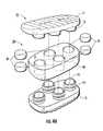
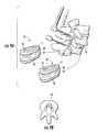
- FIG. 1is an exploded view of an exemplary interbody spacer according to embodiments of the present invention.
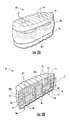
- FIG. 2Ais a side perspective view of the device shown in FIG. 1 .
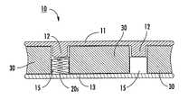
- FIG. 2Bis a cross-sectional view of the device shown in FIG. 2A .
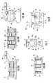
- FIG. 3Ais a partial sectional schematic illustration of a spacer with another flexible and elastically compressible member according to other embodiments of the present invention.
- FIGS. 3B and 3Care partial sectional schematic illustrations of two flexible elastic members according to yet other embodiments of the present invention.
- FIG. 3Dis a partial sectional schematic illustration of an example of an elastic flexible body integrally attached to one of the endplates according to yet other embodiments of the present invention.
- FIG. 3Eis a partial sectional schematic illustration of an example of an elastic flexible body integrally attached to one of the endplates according to yet other embodiments of the present invention.
- FIG. 4Ais an exploded view of another embodiment of an interbody spacer having additional pistons according to embodiments of the present invention.
- FIG. 4Bis an exploded view of an interbody spacer having a single piston according to embodiments of the present invention.
- FIG. 5Ais an exploded view of an interbody spacer with a different configuration of cooperating endplates according to embodiments of the present invention.
- FIG. 5Bis an assembled view of the device shown in FIG. 5A .
- FIG. 6Ais an exploded view of an interbody spacer with yet another configuration of cooperating endplates according to embodiments of the present invention.
- FIG. 6Bis an assembled view of the device shown in FIG. 6A .
- FIG. 7is a schematic partial exploded view of another configuration of a housing and endplates according to embodiments of the present invention.
- FIG. 8is a schematic exploded view of yet another configuration of cooperating endplates according to embodiments of the present invention.
- FIG. 9Ais an exploded schematic view of interbody spacers used with fusion hardware according to embodiments of the present invention.
- FIG. 9Bis an axial view of an implant site according to embodiments of the present invention.
- FIGS. 10A-10Care schematic illustrations of an interbody spacer in position and providing flexing during spinal loading according to embodiments of the present invention.
- FIG. 11is a flow chart of operations that can be used to fabricate surgical implants according to embodiments of the present invention.
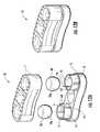
- FIG. 12Ais an exploded view of an interbody spacer according to embodiments of the present invention.
- FIG. 12Bis a side perspective assembled view of the spacer shown in FIG. 12A .
- FIG. 13Ais an exploded view of another interbody spacer similar to that shown in FIG. 12A according to embodiments of the present invention.
- FIG. 13Bis a side perspective assembled view of the device shown in FIG. 13A .
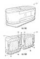
- FIG. 14Ais a side perspective view of an interbody spacer according to embodiments of the present invention.
- FIG. 14Bis a section view of the device shown in FIG. 14A .
- FIG. 14Cis a side perspective view of the device shown in FIG. 14A without the upper endplate.
- FIG. 14Dis a section view of the device shown in FIG. 14B with the device having a pre-load configuration according to embodiments of the present invention.
- FIG. 15Ais a side perspective view of an interbody spacer according to embodiments of the present invention.
- FIG. 15Bis a section view of the device shown in FIG. 15A .
- FIG. 16Ais an exploded view of an interbody spacer according to embodiments of the present invention.
- FIG. 16Bis a side perspective assembled view of the device shown in FIG. 16A .
- FIG. 17Ais a side perspective assembled view of an interbody device according to embodiments of the present invention.
- FIG. 17Bis a section view of the device shown in FIG. 17A .
- FIG. 18Ais a section view of a device similar to that shown in FIG. 16A but with the washers held in towers or extensions according to embodiments of the present invention.
- FIG. 18Bis a section view of the device shown in FIG. 18A illustrating an exemplary compressed (under load) configuration according to embodiments of the present invention.
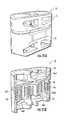
- FIG. 19Ais an exploded view of an interbody spacer according to embodiments of the present invention.
- FIG. 19Bis a side perspective assembled view of the device shown in FIG. 19A .
- FIG. 19Cis a section view of the device shown in FIG. 19A .
- FIG. 19Dis a section view of the device shown in FIG. 19C illustrating an exemplary compressed (under load) configuration according to embodiments of the present invention.
- FIG. 20Ais a side perspective view of yet another interbody spacer according to embodiments of the present invention.
- FIG. 20Bis a section view of the device shown in FIG. 20A .
- FIG. 21Ais a side perspective view of another interbody spacer similar to that shown in FIG. 20A but with the O-rings held in towers or extensions according to embodiments of the present invention.
- FIG. 21Bis a section view of the device shown in FIG. 21A .
- FIG. 22is a side perspective view of a surgical instrument used to place interbody spacers according to embodiments of the present invention.
- phrases such as “between X and Y” and “between about X and Y”should be interpreted to include X and Y.
- phrases such as “between about X and Y”mean “between about X and about Y.”
- phrases such as “from about X to Y”mean “from about X to about Y.”
- first, second, etc.may be used herein to describe various elements, components, regions, layers and/or sections, these elements, components, regions, layers and/or sections should not be limited by these terms. These terms are only used to distinguish one element, component, region, layer or section from another region, layer or section. Thus, a first element, component, region, layer or section discussed below could be termed a second element, component, region, layer or section without departing from the teachings of the present invention.
- the sequence of operations (or steps)is not limited to the order presented in the claims or figures unless specifically indicated otherwise.
- the devices of embodiments of the present inventionare suitable for mammalian patients, including veterinary and human subjects.
- semi-flexiblemeans that the device has the ability to at least partially resiliently deform in at least the axial direction.
- semi-flexiblemeans that the device is semi-flexible and has sufficient rigidity to substantially maintain its shape under normal (non back-bending) loading in the body.
- barrel-likerefers to a shape that has sides that curve (taper) outwardly, then inwardly, relative to a top and/or bottom surface thereof.
- borerefers to a hole or passage without regard to its formation methodology.
- the term “piston”means that an elastic member is held snugly inside a chamber and cooperates with a compression member that can move back and forth (in a substantially axial or longitudinal direction) to exert forces on the elastic member to compress and decompress the elastic member.
- elastic member and “resilient member” (or body)refers to a member that can substantially return to its original form after deformation due to normal compressive loading (in the spine).
- Embodiments of the inventionare particularly suitable as interbody spacers for use in spinal fusion procedures or therapies, such as, for example, posterior lumbar interbody fusion “PLIF” interbody spacers and/or as transforaminal lumbar interbody fusion “TLIF” interbody spacers.
- PLIFposterior lumbar interbody fusion
- TLIFtransforaminal lumbar interbody fusion
- fixation hardware of target vertebraecan be used with the spacer to allow for semi-flexible (dynamic) fusion implants.
- the term “dynamic stabilization”means that the spacer(s) and hardware allow certain types of limited motion but restrict other types of motion, such as, for example, abnormal ranges of motion.
- the spacerscan be configured to provide compression heights of between about 1-2.5 mm, typically about 1 mm.
- embodiments of the inventionare directed to spinal implant devices that employ one or more flexible elastic members that can allow at least some motion of the spine and/or that can act as a dampening material to absorb force impacts and protect adjacent bone structures.
- the devicescan do both.
- the devicescan be configured to allow independent compression of different regions of the device in the body.
- FIGS. 1 , 2 A and 2 Billustrate an exemplary embodiment of an interbody spacer 10 .
- the spacer 10includes upper and lower endplates 11 , 13 that cooperate to be able to deform two resilient and/or elastic members 20 .
- the elastic member 20can be a flexible solid plug 20 p as shown, but other configurations of elastic members may also be used, including metal members such as titanium bodies, O-rings, springs, washers, and the like, as will be discussed below.
- one of the endplatesdefines two spaced apart male portions or members 12 extending in an interior direction while the other endplate 13 (shown as the lower endplate) defines two corresponding female members or portions 14 with cavities 15 that are sized and configured to receive and hold the elastic members 20 .
- the orientation of the device 10can be inverted so that the female member cavity 15 is on the top and extends down (not shown) and the male member 12 extends up.
- the female member cavities 15can have a depth dimension that is longer than the length dimension of the corresponding male member 12 .
- the male member 12may have an interior facing (lowermost or uppermost surface, depending on orientation) arc or dome shape or may be substantially planar or have another suitable configuration.
- the spacer 10can also include an exterior shell or housing 30 with two bores or cavities 31 that are sized and configured to snugly surround the respective female and male member pairs 12 , 14 and a unitary body with a center segment 30 m that spaces the two bores 31 apart.
- the housing body 30 bcan have a longitudinal dimension L and a configuration that allows the upper and lower surfaces thereof to reside proximate (typically abut) the inner faces of the upper and lower endplates 11 , 13 so that there are substantially no gaps or voids between the endplate inner surfaces and the adjacent surface of the housing 30 .
- the housing 30typically frictionally engages both endplates 11 , 13 , but is not required to be sealed to upper or lower surfaces thereof.
- the elastic member(s) 20can substantially fill the volume between the upper and lower surfaces of the male and female members so that there is substantially no free space therebetween irrespective of the spinal loading.
- the spacer 10can include one or more through holes, such as formed through the endplates 11 , 13 and medial portion of the housing 30 m , for promoting bone ingrowth and/or fusion.
- the spacer 10may be configured so that the elastic member 20 is not affixed to either the upper or lower endplate 11 , 13 , and resides in a substantially non-deformed or uncompressed configuration in the female cavity 15 in communication with (typically in contact with) the male portion 12 .
- FIG. 2Billustrates an exemplary “normal” configuration of the elastic member 20 in the spacer 10 .
- the compression of the elastic member 20is between 0.5 mm to about 3 mm, typically between about 1-2 mm, during typical bending and/or torsional loading of the spine.
- the male member 12can slide up and down relative to the female cavity 15 .
- the configuration of the endplates 11 , 13 and/or housing 30can also prevent, inhibit or limit other motions, such as, for example, shear and axial rotation, particularly where more than one pair of male and female members 12 , 14 , respectively, are included.
- the female members 14can have an exterior retention or assembly locking or retention member 16 that engages the inner wall of the respective housing bore or cavity 31 .
- the housing bore or cavity 31can be configured to matably and/or frictionally engage the retention member 16 .
- the retention member 16is a circumferentially extending rib which can be continuous or semi-continuous, and the housing cavity 31 includes a channel 32 in the inner wall that matably engages the retention member 16 .
- the retention feature of the housing 32(where a housing is used) can be formed integrally to the inner wall (e.g., molded as a unitary body).
- the upper and lower endplatesmay be used to attach the upper and lower endplates while allowing compression of the elastic member(s) 20 , such as, for example, teeth, a longitudinally extending rib or ribs, teeth, and the like.
- the rib or ribs 16may be formed in the housing bore inner wall and the channel 32 can be formed into the endplate female portion outer wall (not shown).
- the male member 12 of one endplate 11may also include a retention member 16 (such as but not limited to a rib) that also engages a different channel 32 2 in the inner wall of the housing cavity 31 while the female portion of the other endplate 13 has a retention member 16 that engages a lower channel 32 1 .
- the channel 32 2can be formed to allow some longitudinal movement of the male member 12 , e.g., relative thereto, typically between about 1-3 mm, in order for the male portion or member 12 to be able to compress the elastic member 20 under appropriate loading to provide dynamic stabilization and some flexibility of the implant in conjunction with fusion of two adjacent vertebrae levels.
- one channel 32 1can be sized and configured to more snugly engage the corresponding retention feature or member 16 than the other channel 32 2 .
- the retention member or feature 16 of the male portion 12may alternatively have a smaller dimension than that of the female portion 14 , and the channels 32 1 , 32 2 can have the same dimensions (not shown) to allow the desired longitudinal movement.
- At least one endplate 11 , 13may include fluid apertures and channels 18 that allow local fluid to enter into the inner chamber and contact the elastic member 20 .
- the channels and associated entry apertures 18can reside over each underlying or overlying female cavity 15 .
- the upper or lower external surfaces of the endplates 11 , 13can have a series of steps or ridges 19 for contacting local vertebrae.
- the spacer 10can also have bone chip receptacles in the endplates 11 , 13 for in-growth fixation (not shown) as is known to those of skill in the art.
- the spacer 10can include one or more substantially planar porous and/or permeable membranes (not shown) that are sized and configured to overlie or reside adjacent the top and/or bottom surfaces of the elastic member 20 .
- the membranesmay be foil membranes.
- the elastic member (or elastic members) 20can be any suitable elastic member, such as one or a plurality of flexible plugs 20 p (shown in FIG. 1 ), or other type of elastic or resilient member.
- the elastic membercan comprise one or more springs 20 s , such as leaf springs, coil springs, Belleville springs, Clover-Dome spring washers (see, e.g., U.S. Pat. No.
- any other type of flexible elastic memberincluding, for example (polyurethane or other suitable material) O-rings 20 o .
- Combinations of different types of elastic or resilient members and/or more than one of the same typemay also be used.
- different types of elastic members 20can reside in different cavities of the spacer 10 (the cavity being formed by either or both the housing body cavity or female cavity 31 , 15 ).
- FIGS. 3B and 3Cillustrate a configuration that uses two elastic bodies 20 1 , 20 2 that cooperate with the endplates 11 , 13 .
- a spring 20 s and small plug 20 preside between the upper and lower endplates 11 , 13 and can provide shock absorption and spinal motion.
- the male member 12can include a shelf 12 s portion that merges into a lower neck portion 12 n .
- the shelf portion 12 scan be configured to compress a spring 20 s held under the shelf and the lower endplate 13 .
- the lower endplate 13can include a stepped cavity configuration with a larger portion merging into a narrower lower portion 15 n that is sized and configured to slidably receive the neck 12 n of the male member.
- a flexible elastic plug 20 2can be held in the lower portion of the cavity 15 n .
- the spring 20 scan compress and the plug 20 2 can deform and fill the narrow cavity 15 n when substantially fully constrained.
- the plug 20 pcan provide a “soft stop” before the male and female components of the endplates bottom out.
- maximum displacement of at least one of the endplates 11 , 13can occur when the plug 20 p is deformed to fully fill the lower cavity 15 n and thereby stop the downward movement of the upper endplate 11 .
- the plug 20 2can be substantially incompressible and may comprise or be a solid PVA hydrogel body.
- FIG. 3Dillustrates that the plug 20 p can be integrally attached to the male member 12 .
- the plug 20 p shown in the embodiment of FIG. 1can be modified as shown in FIG. 3E to be integrally attached to the male member 12 .
- one plug 20 pcan be attached to one endplate, such as the male member, and another plug can reside in the same cavity (aligned) and under the attached plug, but not be attached.
- a plug 20 pmay also be attached to a floor of the female cavity 15 .
- the plugs 20 pe.g., of solid polymeric material such as PVA hydrogel
- the plugs 20 pcan provide shock absorption.
- the elastic membercan have variable stiffness, customized stiffness or multiple different stiffnesses, typically over a length direction, but optionally also side-to-side.
- the plug-type elastic member 20 pcan be a solid unitary body of a biocompatible material, including metals and/or polymers.
- Some exemplary polymersinclude, for example, PEEK, polyurethane, silicone, hydrogels, collagens, hyalurons, polyvinyl pyrrolidone, poly HEMA, HYPANTM, Salubria®, high durometer PCU (polycarbonurethane) and other synthetic polymers that are configured to have a desired range of flexible or resilient mechanical properties, such as a suitable elastic stiffness and/or elastic modulus.
- the external housing 30where used, can be formed of similar materials.
- the elastic member 20is a solid molded unitary rigid polymer plug 20 p such as PEEK and/or a poly-vinyl alcohol (PVA) crystalline hydrogel plug defining a semi-compressible medium.
- the PVA bodycan comprise a high molecular-weight PVA material that when solubilized (with saline or water or a suitable aqueous solution), heated, molded and subjected to several freeze-thaw cycles, produces a crystalline flexible biocompatible structure suitable for implantation in the spine.
- the external housing 30where used, can again be formed of similar materials.
- the elastic member(s) 20 pcan have any suitable shape including spherical, box-like, cylindrical or other geometric shape, which may be hollow or solid.
- the plug 20 pcan have a barrel-like shape and can have a dome or upper and/or projecting lower surface with a convex shape and fit snugly inside the female cavity 15 .
- the housing 30can be formed of a biocompatible polymer.
- the housing 30can be a unitary polymer body that is also at least partially flexible and can have a relatively thin outer wall that covers the male/female member 12 , 14 pairs.
- the housing 30can be a PVA freeze-thaw solid molded flexible body that can be substantially incompressible or compressible (e.g., and can be formed of the same material as some embodiments of the elastic member(s) 20 ). Where both the housing 30 and the elastic member 20 are formed as solid molded freeze-thaw PVA hydrogels, the elastic member 20 may have increased rigidity or decreased rigidity relative to the housing 30 .
- the endplates 11 , 13can be formed of any suitable substantially rigid biocompatible material, including, for example, ceramics, hardened polymers, and metals such as titanium or combinations thereof.
- the elastic member(s) 20may also include a flexible sleeve or other constraint for the elastic member(s) 20 to provide support to inhibit lateral expansion.
- FIGS. 1 , 2 A, and 2 Billustrate that in some embodiments, the spacer 10 can have a dual chamber “piston” design.
- the piston 10 pcan be defined by the endplates 11 , 13 and the elastic member 20 .
- the housing bore 31can also form a portion of the piston by defining a portion of the holding chamber such that the piston is defined by the endplates 11 , 13 , the housing 30 and the elastic member 20 .
- the spacer 10 (and piston(s))are non-articulating.
- the spacer 10can be configured with other numbers of chambers and/or pistons 10 p .
- more than two pistons 10 pcan be used, such as, for example, between about 3-10, shown as four.
- FIG. 4Billustrates that the spacer 10 can have a single piston 10 p.
- FIGS. 5A and 5Billustrate that each endplate 11 , 13 can include a male portion or member 12 that enters into opposing end portions of the cavity 31 of the housing and can hold, block or trap the elastic member 20 .
- the housing 30defines a portion of the sidewall of the piston chamber.
- One or both of the male members 12can be configured to move in a longitudinal direction to compress the elastic member 20 .
- the upper or lower male member 12may have a longer length relative to the other aligned member 12 .
- FIGS. 6A and 6Billustrate that one of the endplates 13 shown can have a substantially planar interior facing surface 13 p with the other endplate 11 having one or more male members 12 .
- the elastic member 20is held in the cavity 31 under (or above) the male member 12 .
- the orientation of the device showncan be reversed for implantation or positioning in the body.
- the housing 30defines a portion of the sidewall of the piston chamber.
- the planar endplate 13may include a shallow cavity or a raised edge 13 r with a groove or rib proximate each cavity 31 to engage the cavity of the housing 31 .
- the planar endplate 13may include a ridge or groove about its perimeter to engage a receiving portion of the housing (not shown) or other housing engaging means.
- FIG. 8illustrates another embodiment of the spacer 10 .
- each endplate 11 , 13may have both a female and male member 14 , 12 , respectively, that is aligned with the corresponding male and female member 12 , 14 on the opposing side of the elastic member 20 about a housing cavity 31 .
- FIGS. 9A and 9Billustrate that two spacers 10 can be placed (side-by-side) at each vertebrae space (disc) level that is being treated and used with fusion hardware (e.g., posterior rods and screws) (the components are not shown to scale).
- FIGS. 10A-10Cillustrates exemplary dynamic stabilization configurations of the spacers(s) 10 .
- FIG. 11is a flow chart of exemplary operations that can be carried out to form a spacer according to embodiments of the present invention.
- Rigid upper and lower endplatesare provided (block 100 ).
- At least one elastic memberis provided (block 120 ).
- the elastic member and/or housing bodycan be unitary molded solid PVA freeze-thaw bodies (block 115 ).
- One endplateis attached to the other (block 125 ).
- the assembled endplatescan be attached to preload the elastic member with a desired pre-load force/configuration (block 135 ) and define an interbody spinal spacer.
- the spacercan be sterilized and placed in a sterile medical package (block 140 ).
- a molded housing with at least one cavitycan optionally be provided (block 110 ).
- the molded housingwhere used, can be a flexible polymer and/or elastomeric primary shell.
- the housingcan be flexible and stretched to fit over and snugly encase the female members.
- the elastic membercan be placed in the cavity or bore residing between the endplates (e.g., one or more of a plug, O'rings, springs, or washers).
- FIGS. 12A , 13 A, 14 B, 14 C 15 B, 17 B and 18 Aillustrate a spacer 10 with two chambers or cavities 15 .
- the lower endplate 13can include upwardly extending circular walls with inner portions having radially extending projections that form internal click fingers 14 f that matably engage (e.g., snap-fit) to the upper end plate 11 .
- the upper endplate 11includes a wall extending downwardly with a finger 13 f that matably engages an upwardly extending wall with a finger 14 f of the lower endplate 13 .
- the finger 14 fmay reside on an inner portion of the wall and be provided as an arc segment “ ⁇ ” ( FIG. 12A ) of between about 10-120 degrees, typically between about 15-90 degrees, and more typically between about 25-45 degrees. Upwardly extending or downwardly extending slots may reside on one or both sides of the finger 14 f as shown in the figures.
- the recesses (particularly the two outer circular recesses) shown on the upper surface of the endplate 11 in FIG. 12Aare optional and may not be used, particularly for smaller size spacers.
- FIGS. 19C , 20 B and 21 Billustrate an alternate snap-fit or click-attachment assembly configuration.
- the lower end plate 13includes an interior substantially vertically extending through-cavity.
- the lower end plate 13includes an interior (medial) substantially vertically extending through channel 141 with a lower portion having a ledge 14 .
- the upper endplateincludes a clip member 140 f with a lower portion with a tapered end (finger) that abuts the female member ledge 142 to lock the upper endplate to the lower endplate.
- FIGS. 20B and 21Billustrate that the clip member 140 f can be integral with the upper endplate 11 .
- the upper and lower endplates 11 , 13can be configured to assemble together using the clip member 14 f , 140 f as a snap fit attachment configuration that pre-loads the resilient member 20 (e.g. 20 p , 20 o , 20 s ).
- FIG. 14Dshows an example of a pre-load configuration of the spacer according to embodiments of the present invention.
- the pre-loadcan be customized to fit the particular implant location or patient requirement.
- the same pre-load featurecan apply to other resilient members used, e.g., the O-ring 20 o , or springs 20 s ( FIGS. 17B , 20 B) when the endplates 11 , 13 are snap-fitted or otherwise attached together.
- An exemplary range of pre-loadscan be between about 10N to about 600N, typically between about 100N to 500N, but such pre-load forces may vary and be greater or lower than the forces in these ranges.
- the pre-load forcecan get the laxity out of the system and provide some resistance to compression in a neutral position. It is contemplated, that the pre-load can be customized or provided in different selectable ranges so that a clinician can select a pre-load based on patient-specific characteristics.
- FIGS. 15A , 15 B, 18 A, 21 A, 21 Billustrate spacers with “tower” extensions 11 ext, 13 ext.
- the upper endplate 11includes an upper portion with a surface that is configured to contact local bone and a second surface that is vertically spaced apart from and resides below the upper portion, the second surface defining a ceiling for the chamber or cavity holding the resilient member 20 ( 20 p , 20 s , 20 o ).
- the lower endplate 13includes a lower portion with a surface that is configured to contact local bone and a second surface that is vertically spaced apart from and resides above from the lower portion. The second surface is attached to or defines the female member.
- the height of the gap space or extension between the upper surface and the second surfacecan have a height “h 1 ”.
- the height of the gap space or extension between the lower surface and the second surface associated with the female membercan have a height “h 2 ”.
- the heights h 1 and h 2can be substantially the same or one may be greater than the other.
- the h 1 heightcan be 10%-30% or more than the lower height h 2 or vice versa.
- FIGS. 12A , 12 B, 13 A, 13 B, 14 A- 14 C, 15 A and 15 Ball illustrate spacers 10 with elastic members 20 that are configured as solid or hollow plugs 20 p similar to the embodiments discussed above with respect to FIGS. 1 and 2A .
- FIGS. 16A , 16 B, 17 A, 17 B and 18 Aall illustrate spacers 10 with elastic members 20 that are defined by or include stacked spring washers 20 s such as dome spring disk washers.
- stacked spring washers 20 ssuch as dome spring disk washers.
- the washerscan be stacked in triplet subsets as shown in FIG. 16A and 17B , as sequence “3A3B3A3B” meaning (3 washers in direction A, then 3 oriented in direction B, etc.).
- washer pairscan be stacked, AA, BB, AA, BB, AA. Other numbers of washers or washer sub-combinations may also be used.
- the same or different stack configurations or number of washers in a stackcan vary in each chamber in the spacer 10 and the stack can be configured so that the design is a non-repeating pattern.
- the spring rate for spacers with two stackscan be between about 300N/mm-800 N/mm (typically about 780 N/mm for a 12 piece stack in the 3A3B3A3B configuration and about 300N/mm for the 10 piece stack configuration discussed above.
- Belleville washers, wave washers or disc spring washersmay also be used alone or in combination with the dome spring washers.
- the dome spring washersare stacked in series of two or three in different orientations.
- the male membermay extend upward or the chambers may contain the washers without any such male member.
- the male member(s)can help maintain alignment of the washers in the chamber/cavity when exposed to shear stresses, torsion or other dynamic loads.
- FIGS. 19A-C , 20 A, 20 B, 21 A and 21 Ball illustrate spacers 10 with elastic members 20 that are stacked O-rings. As shown, three O-rings 20 o are vertically stacked and abut each other in an annular chamber. However, two, four, five, six or even more O-rings may be used.
- the male member 12can extend through a center channel 141 as discussed above and/or include an annular projection that compresses the O-rings. Other attachment configurations can be used.
- FIGS. 18B and 19Dillustrate examples of the spacers 10 in an exemplary compressed (loaded) configuration.
- the spacers 10can be evenly distributed structures that are strong, stiff and allow from dynamic stabilization and can withstand normal torsion and shear.
- the spacerscan include openings on the top and bottom for bone in-growth.
- the devices 10can include a total lordotic angle of about 5 degrees.
- the devices 10can be configured with dual (or more) independent compressibility upon exposure to forces based on the spaced apart elastic members in two or more chambers.
- the devices 10can allow for about 1-2.5 mm of compression, typically about 1 mm compression.
- the devices 10can be configured to apply a pre-load onto the resilient member 20 that may be customized to fit the particular implant location and/or patient requirement.
- the devices 10can be configured with a “soft stop” that occurs before the maximum “hard stop” of the endplates 11 , 13 using the endplate/resilient member 20 configurations described herein which can provide more physiological loading patterns.
- the elastic member(s)can have variable stiffness, customized stiffness or multiple different stiffnesses.
- FIG. 22illustrates an example of a surgical tool 200 that can be used to place the spacer 10 in the spine.
- the tool 200can include a front lead in chamfer and can include a track on the side for instrument docking.
- the toolcan include a front end 210 that clicks around the implant and a tubular portion can be pushed forward to lock the front end 210 .
- the implant/spacer 10can be inserted into the spine (and the tool may be suitable for impaction with a mallet on a rear end portion of the hand piece).
Landscapes
- Health & Medical Sciences (AREA)
- Engineering & Computer Science (AREA)
- Biomedical Technology (AREA)
- Orthopedic Medicine & Surgery (AREA)
- Transplantation (AREA)
- Neurology (AREA)
- Oral & Maxillofacial Surgery (AREA)
- Cardiology (AREA)
- Heart & Thoracic Surgery (AREA)
- Vascular Medicine (AREA)
- Life Sciences & Earth Sciences (AREA)
- Animal Behavior & Ethology (AREA)
- General Health & Medical Sciences (AREA)
- Public Health (AREA)
- Veterinary Medicine (AREA)
- Physical Education & Sports Medicine (AREA)
- Prostheses (AREA)
Abstract
Description
Claims (3)
Priority Applications (1)
| Application Number | Priority Date | Filing Date | Title |
|---|---|---|---|
| US12/503,937US8172902B2 (en) | 2008-07-17 | 2009-07-16 | Spinal interbody spacers |
Applications Claiming Priority (2)
| Application Number | Priority Date | Filing Date | Title |
|---|---|---|---|
| US8141408P | 2008-07-17 | 2008-07-17 | |
| US12/503,937US8172902B2 (en) | 2008-07-17 | 2009-07-16 | Spinal interbody spacers |
Publications (2)
| Publication Number | Publication Date |
|---|---|
| US20100016970A1 US20100016970A1 (en) | 2010-01-21 |
| US8172902B2true US8172902B2 (en) | 2012-05-08 |
Family
ID=41530998
Family Applications (1)
| Application Number | Title | Priority Date | Filing Date |
|---|---|---|---|
| US12/503,937Expired - Fee RelatedUS8172902B2 (en) | 2008-07-17 | 2009-07-16 | Spinal interbody spacers |
Country Status (1)
| Country | Link |
|---|---|
| US (1) | US8172902B2 (en) |
Cited By (9)
| Publication number | Priority date | Publication date | Assignee | Title |
|---|---|---|---|---|
| US20120046750A1 (en)* | 2009-03-05 | 2012-02-23 | Dsm Ip Assets B.V. | Spinal fusion cage |
| US20160015527A1 (en)* | 2008-03-07 | 2016-01-21 | DePuy Synthes Products, Inc. | Expandable interbody spacer device |
| US20200046511A1 (en)* | 2018-08-07 | 2020-02-13 | Minimally Invasive Spinal Technology, LLC | Device and method for correcting spinal deformities in patients |
| WO2020198161A1 (en)* | 2012-03-16 | 2020-10-01 | Sag, Llc | Surgical instrument for implanting a semi-rigid medical implant |
| US11147687B2 (en)* | 2020-01-02 | 2021-10-19 | Solco Biomedical Co., Ltd. | Cage for spinal surgery |
| US11197765B2 (en) | 2019-12-04 | 2021-12-14 | Robert S. Bray, Jr. | Artificial disc replacement device |
| US11259933B2 (en)* | 2019-09-06 | 2022-03-01 | Globus Medical Inc. | Expandable motion preservation spacer |
| US11839554B2 (en) | 2020-01-23 | 2023-12-12 | Robert S. Bray, Jr. | Method of implanting an artificial disc replacement device |
| US20240016523A1 (en)* | 2022-07-13 | 2024-01-18 | Globus Medical, Inc. | Reverse dynamization implants |
Families Citing this family (30)
| Publication number | Priority date | Publication date | Assignee | Title |
|---|---|---|---|---|
| US12232975B2 (en) | 2008-02-22 | 2025-02-25 | Howmedica Osteonics Corp. | Lockable spinal implant |
| US8992620B2 (en) | 2008-12-10 | 2015-03-31 | Coalign Innovations, Inc. | Adjustable distraction cage with linked locking mechanisms |
| US20100145455A1 (en) | 2008-12-10 | 2010-06-10 | Innvotec Surgical, Inc. | Lockable spinal implant |
| US8932355B2 (en) | 2008-02-22 | 2015-01-13 | Coalign Innovations, Inc. | Spinal implant with expandable fixation |
| US11224521B2 (en) | 2008-06-06 | 2022-01-18 | Providence Medical Technology, Inc. | Cervical distraction/implant delivery device |
| US10842645B2 (en) | 2008-08-13 | 2020-11-24 | Smed-Ta/Td, Llc | Orthopaedic implant with porous structural member |
| US20100042213A1 (en) | 2008-08-13 | 2010-02-18 | Nebosky Paul S | Drug delivery implants |
| JP2012500058A (en)* | 2008-08-13 | 2012-01-05 | スメド−ティーエイ/ティーディー・エルエルシー | Orthopedic implant with a porous structural member |
| US9700431B2 (en)* | 2008-08-13 | 2017-07-11 | Smed-Ta/Td, Llc | Orthopaedic implant with porous structural member |
| US9616205B2 (en) | 2008-08-13 | 2017-04-11 | Smed-Ta/Td, Llc | Drug delivery implants |
| WO2010025386A1 (en) | 2008-08-29 | 2010-03-04 | Smed-Ta/Td, Llc | Orthopaedic implant |
| US8277509B2 (en)* | 2009-12-07 | 2012-10-02 | Globus Medical, Inc. | Transforaminal prosthetic spinal disc apparatus |
| US8956414B2 (en) | 2010-04-21 | 2015-02-17 | Spinecraft, LLC | Intervertebral body implant, instrument and method |
| US8377140B2 (en) | 2011-01-12 | 2013-02-19 | Ebi, Llc | Expandable spinal implant device |
| WO2012103254A2 (en) | 2011-01-25 | 2012-08-02 | Nuvasive, Inc. | Spinal implants for rotationally adjusting vertebrae |
| US9277946B2 (en)* | 2011-09-06 | 2016-03-08 | Amendia, Inc. | Spinal fusion system |
| US9757247B2 (en) | 2012-10-01 | 2017-09-12 | DePuy Synthes Products, Inc. | Interbody fusion implant |
| FR2996444B1 (en)* | 2012-10-08 | 2015-10-23 | Medicrea International | INTERVERTEBRAL DISC PROSTHESIS |
| US9238319B2 (en)* | 2013-03-14 | 2016-01-19 | DePuy Synthes Products, Inc. | Hybrid intervertebral disc spacer device and method of manufacturing the same |
| EP2777632B1 (en)* | 2013-03-15 | 2020-04-22 | Howmedica Osteonics Corp. | Adjustable distraction cage with linked locking mechanisms. |
| JP5934161B2 (en) | 2013-09-09 | 2016-06-15 | 武蔵エンジニアリング株式会社 | Nozzle and liquid material discharge apparatus including the nozzle |
| WO2016144150A1 (en)* | 2015-03-06 | 2016-09-15 | Marin Salvador José | Expandable system for intersomatic fusion and method for the use thereof |
| US10548738B2 (en) | 2016-04-07 | 2020-02-04 | Howmedica Osteonics Corp. | Expandable interbody implant |
| WO2017192627A1 (en)* | 2016-05-02 | 2017-11-09 | Spinal Simplicity, Llc | Spinal interbody with compressive fusion features |
| AU2017203369B2 (en) | 2016-05-20 | 2022-04-28 | Vb Spine Us Opco Llc | Expandable interbody implant with lordosis correction |
| AU2017228529B2 (en) | 2016-09-12 | 2022-03-10 | Vb Spine Us Opco Llc | Interbody implant with independent control of expansion at multiple locations |
| AU2017251734B2 (en) | 2016-10-26 | 2022-10-20 | Vb Spine Us Opco Llc | Expandable interbody implant with lateral articulation |
| US20200289285A1 (en)* | 2017-11-16 | 2020-09-17 | Providence Medical Technology, Inc. | Arthroplasty implant for a facet joint |
| WO2020061464A1 (en) | 2018-09-21 | 2020-03-26 | Providence Medical Technology, Inc. | Vertebral joint access and decortication devices and methods of using |
| US20240033100A1 (en)* | 2022-07-29 | 2024-02-01 | Warsaw Orthopedic, Inc. | Interbody implant having endplates connected by struts |
Citations (140)
| Publication number | Priority date | Publication date | Assignee | Title |
|---|---|---|---|---|
| US4309777A (en) | 1980-11-13 | 1982-01-12 | Patil Arun A | Artificial intervertebral disc |
| US4932969A (en) | 1987-01-08 | 1990-06-12 | Sulzer Brothers Limited | Joint endoprosthesis |
| WO1994004100A1 (en) | 1992-08-24 | 1994-03-03 | Societe De Fabrication De Materiel Orthopedique - Sofamor | Intervertebral disk prosthesis |
| US5370697A (en) | 1992-04-21 | 1994-12-06 | Sulzer Medizinaltechnik Ag | Artificial intervertebral disk member |
| US5425772A (en) | 1993-09-20 | 1995-06-20 | Brantigan; John W. | Prosthetic implant for intervertebral spinal fusion |
| US5458642A (en) | 1994-01-18 | 1995-10-17 | Beer; John C. | Synthetic intervertebral disc |
| US5480442A (en) | 1993-06-24 | 1996-01-02 | Man Ceramics Gmbh | Fixedly adjustable intervertebral prosthesis |
| US5534028A (en) | 1993-04-20 | 1996-07-09 | Howmedica, Inc. | Hydrogel intervertebral disc nucleus with diminished lateral bulging |
| FR2730159B1 (en) | 1995-02-06 | 1997-04-25 | Teule Jean Germain | PROSTHESIS FOR INTERVERTEBRAL DISC |
| US5674294A (en) | 1993-09-14 | 1997-10-07 | Commissariat A L'energie Atomique | Intervertebral disk prosthesis |
| US5683465A (en) | 1996-03-18 | 1997-11-04 | Shinn; Gary Lee | Artificial intervertebral disk prosthesis |
| US5893889A (en) | 1997-06-20 | 1999-04-13 | Harrington; Michael | Artificial disc |
| WO2000035382A1 (en) | 1998-12-11 | 2000-06-22 | Dimso (Distribution Medicale Du Sud-Ouest) | Intervertebral disc prosthesis with reduced friction |
| JP3275056B2 (en) | 1992-04-02 | 2002-04-15 | サンユレック株式会社 | Urethane resin composition |
| JP3275055B2 (en) | 1991-11-19 | 2002-04-15 | 株式会社トーキン | Rare earth bonded magnet |
| US6375682B1 (en) | 2001-08-06 | 2002-04-23 | Lewis W. Fleischmann | Collapsible, rotatable and expandable spinal hydraulic prosthetic device |
| US6395032B1 (en) | 1998-12-11 | 2002-05-28 | Dimso (Distribution Medicale Du Sud-Ouest) | Intervertebral disc prosthesis with liquid chamber |
| US6402785B1 (en) | 1999-06-04 | 2002-06-11 | Sdgi Holdings, Inc. | Artificial disc implant |
| US6419704B1 (en) | 1999-10-08 | 2002-07-16 | Bret Ferree | Artificial intervertebral disc replacement methods and apparatus |
| US6419706B1 (en) | 1997-12-19 | 2002-07-16 | Sofamor S.N.C. | Partial disc prosthesis |
| US6468310B1 (en) | 2001-07-16 | 2002-10-22 | Third Millennium Engineering, Llc | Intervertebral spacer device having a wave washer force restoring element |
| US20030023311A1 (en) | 2000-08-30 | 2003-01-30 | Trieu Hai H. | Intervertebral disc nucleus implants and methods |
| US6520996B1 (en) | 1999-06-04 | 2003-02-18 | Depuy Acromed, Incorporated | Orthopedic implant |
| US6527806B2 (en) | 2001-07-16 | 2003-03-04 | Third Millennium Engineering, Llc | Intervertebral spacer device having a spiral wave washer force restoring element |
| US6527804B1 (en) | 1998-12-11 | 2003-03-04 | Dimso (Distribution Medicale Du Sud-Quest) | Intervertebral disk prosthesis |
| US20030045939A1 (en) | 2001-08-24 | 2003-03-06 | Simon Casutt | Artificial intervertebral disc |
| US6533818B1 (en) | 2000-04-26 | 2003-03-18 | Pearl Technology Holdings, Llc | Artificial spinal disc |
| USD473650S1 (en) | 2000-10-27 | 2003-04-22 | Lifenet | Bone implant |
| US6572653B1 (en) | 2001-12-07 | 2003-06-03 | Rush E. Simonson | Vertebral implant adapted for posterior insertion |
| US6579320B1 (en) | 1998-12-11 | 2003-06-17 | Stryker Spine | Intervertebral disc prosthesis with contact blocks |
| US6579318B2 (en) | 2000-06-12 | 2003-06-17 | Ortho Development Corporation | Intervertebral spacer |
| US6582468B1 (en) | 1998-12-11 | 2003-06-24 | Spryker Spine | Intervertebral disc prosthesis with compressible body |
| US6608117B1 (en) | 2001-05-11 | 2003-08-19 | Nanosystems Research Inc. | Methods for the preparation of cellular hydrogels |
| US6610093B1 (en) | 2000-07-28 | 2003-08-26 | Perumala Corporation | Method and apparatus for stabilizing adjacent vertebrae |
| US6626943B2 (en) | 2001-08-24 | 2003-09-30 | Sulzer Orthopedics Ltd. | Artificial intervertebral disc |
| US20030199982A1 (en) | 1998-09-04 | 2003-10-23 | Sdgi Holdings, Inc. | Peanut spectacle multi discoid thoraco-lumbar disc prosthesis |
| US20030208271A1 (en) | 2001-07-03 | 2003-11-06 | Axiomed Spine Corporation | Artificial disc |
| US6645249B2 (en) | 2001-10-18 | 2003-11-11 | Spinecore, Inc. | Intervertebral spacer device having a multi-pronged domed spring |
| US6669732B2 (en) | 1997-10-17 | 2003-12-30 | Depuy Acromed, Inc. | Spinal disc |
| US6682562B2 (en) | 2000-03-10 | 2004-01-27 | Eurosurgical Sa | Intervertebral disc prosthesis |
| US20040024461A1 (en)* | 2002-05-10 | 2004-02-05 | Ferree Bret A. | Spring and spherical joint artificial disc replacements |
| US20040034421A1 (en) | 2001-07-16 | 2004-02-19 | Errico Joseph P. | Circumferentially buried wire mesh endplate attachment device for use with an orthopedic device |
| US20040034437A1 (en) | 2002-08-15 | 2004-02-19 | Reinhold Schmieding | Osteochondral repair using plug fashioned from whole distal femur or condyle formed of hydrogel composition |
| WO2004016205A2 (en) | 2002-08-15 | 2004-02-26 | Coppes Justin K | Intervertebral disc implant |
| US6705813B2 (en) | 2002-02-07 | 2004-03-16 | Pierre P. Schwab | Snap disc device |
| US6719794B2 (en) | 2001-05-03 | 2004-04-13 | Synthes (U.S.A.) | Intervertebral implant for transforaminal posterior lumbar interbody fusion procedure |
| US6726721B2 (en) | 1999-09-30 | 2004-04-27 | Replication Medical Inc. | Hydrogel-based prosthetic device for replaceing at least a part of the nucleus of a spinal disc |
| US6733532B1 (en) | 1998-12-11 | 2004-05-11 | Stryker Spine | Intervertebral disc prosthesis with improved mechanical behavior |
| US20040093082A1 (en) | 2002-04-19 | 2004-05-13 | Ferree Bret A. | Mobile-bearing artificial disc replacement |
| US20040093087A1 (en) | 2002-11-05 | 2004-05-13 | Ferree Bret A. | Fluid-filled artificial disc replacement (ADR) |
| US6749635B1 (en) | 1998-09-04 | 2004-06-15 | Sdgi Holdings, Inc. | Peanut spectacle multi discoid thoraco-lumbar disc prosthesis |
| US20040127991A1 (en) | 2002-10-22 | 2004-07-01 | Ferree Bret A. | Biaxial artificial disc replacement |
| US20040133278A1 (en) | 2002-10-31 | 2004-07-08 | Marino James F. | Spinal disc implant |
| US20040143332A1 (en) | 2002-10-31 | 2004-07-22 | Krueger David J. | Movable disc implant |
| US20040220672A1 (en) | 2003-05-03 | 2004-11-04 | Shadduck John H. | Orthopedic implants, methods of use and methods of fabrication |
| US20040267369A1 (en) | 2002-04-25 | 2004-12-30 | Matthew Lyons | Artificial intervertebral disc |
| US6837904B2 (en) | 2001-07-16 | 2005-01-04 | Spinecore, Inc. | Method of surgically treating scoliosis |
| US20050055095A1 (en) | 2001-07-16 | 2005-03-10 | Errico Joseph P. | Artificial intervertebral disc trials having a cylindrical engagement surface |
| US20050055099A1 (en) | 2003-09-09 | 2005-03-10 | Ku David N. | Flexible spinal disc |
| US20050085909A1 (en) | 2003-10-15 | 2005-04-21 | Sdgi Holding, Inc. | Semi-constrained and mobile-bearing disc prosthesis |
| WO2005044151A1 (en) | 2003-11-03 | 2005-05-19 | Ulrich Gmbh & Co. Kg | Implant for placing between vertebral bodies |
| US20050113925A1 (en) | 2003-10-17 | 2005-05-26 | Olivier Carli | Lumbar disc prostheses |
| US20050149189A1 (en) | 2004-01-07 | 2005-07-07 | Mokhtar Mourad B. | Intervertebral disk prosthesis |
| US20050159818A1 (en) | 2002-06-26 | 2005-07-21 | Jason Blain | Total disc replacement system and related methods |
| US20050178395A1 (en) | 2003-11-20 | 2005-08-18 | Angiotech International Ag | Polymer compositions and methods for their use |
| US20050192674A1 (en) | 1999-10-08 | 2005-09-01 | Ferree Bret A. | Prosthetic joints with contained compressible resilient members |
| US20050203626A1 (en) | 2004-03-15 | 2005-09-15 | Sdgi Holdings, Inc. | System and method for stabilizing a prosthetic device |
| US20050216084A1 (en) | 2003-04-22 | 2005-09-29 | Fleischmann Lewis W | Collapsible, rotatable, and tiltable hydraulic spinal disc prosthesis system with selectable modular components |
| US20050216092A1 (en) | 2004-03-23 | 2005-09-29 | Sdgi Holdings, Inc. | Constrained artificial implant for orthopaedic applications |
| US20050216081A1 (en) | 2004-03-29 | 2005-09-29 | Taylor Brett A | Arthroplasty spinal prosthesis and insertion device |
| US6960232B2 (en) | 2002-04-25 | 2005-11-01 | Blackstone Medical, Inc. | Artificial intervertebral disc |
| JP2005329232A (en) | 2004-05-18 | 2005-12-02 | Zimmer Gmbh | Intervertebral disk implant |
| US20050273169A1 (en) | 2004-02-23 | 2005-12-08 | Thomas Purcell | Artificial intervertebral disc assembly |
| US20050273178A1 (en) | 2004-02-06 | 2005-12-08 | Boyan Barbara D | Load bearing biocompatible device |
| US20050273170A1 (en) | 2004-06-08 | 2005-12-08 | Navarro Richard R | Prosthetic intervertebral spinal disc with integral microprocessor |
| US7001433B2 (en) | 2002-05-23 | 2006-02-21 | Pioneer Laboratories, Inc. | Artificial intervertebral disc device |
| US20060041314A1 (en) | 2004-08-20 | 2006-02-23 | Thierry Millard | Artificial disc prosthesis |
| US20060089720A1 (en) | 2004-10-22 | 2006-04-27 | Michael Schneier | Dynamic spinal implant or joint replacement |
| US7052515B2 (en) | 2001-12-07 | 2006-05-30 | Simonson Rush E | Vertebral implant with dampening matrix adapted for posterior insertion |
| US7060099B2 (en) | 2003-06-26 | 2006-06-13 | Scient' X | Disk prosthesis for cervical vertebrae with controlled clearance |
| US7066958B2 (en) | 2002-05-10 | 2006-06-27 | Ferree Bret A | Prosthetic components with partially contained compressible resilient members |
| US7066960B1 (en) | 2002-06-28 | 2006-06-27 | Dickman Curtis A | Intervertebral disk replacement |
| US20060142860A1 (en) | 2003-04-04 | 2006-06-29 | Theken Disc, Llc | Artificial disc prosthesis |
| US20060155377A1 (en) | 2002-11-05 | 2006-07-13 | Jacques Beaurain | Intervertebral disk prosthesis |
| US20060188487A1 (en) | 2005-02-23 | 2006-08-24 | Zimmer Technology, Inc. | Blend hydrogels and methods of making |
| US20060217809A1 (en) | 2005-03-24 | 2006-09-28 | Accin Corporation | Intervertebral disc replacement device |
| US7118599B2 (en) | 2001-07-16 | 2006-10-10 | Spinecore, Inc. | Artificial intervertebral disc |
| US20060235531A1 (en) | 2004-10-18 | 2006-10-19 | Karin Buettner-Janz | Intervertebral disc prosthesis with transversally arched, curved cylindrical articulation surfaces for the lumbar and cervical spine |
| US20060241772A1 (en) | 2004-10-18 | 2006-10-26 | Karin Buettner-Janz | Physiologically movable intervertebral disc prosthesis for the lumbar and cervical spine |
| US20060241765A1 (en) | 2003-04-03 | 2006-10-26 | Burn Peter J | Load bearing intervertebral disk |
| US20060259144A1 (en) | 2004-01-27 | 2006-11-16 | Warsaw Orthopedic Inc. | Hybrid intervertebral disc system |
| USD533277S1 (en) | 2005-11-04 | 2006-12-05 | Quantum Orthopedics, Inc. | Interbody fusion device |
| US20060276900A1 (en) | 2005-06-01 | 2006-12-07 | Carpenter Clyde T | Anatomic total disc replacement |
| US7156876B2 (en) | 2002-10-09 | 2007-01-02 | Depuy Acromed, Inc. | Intervertebral motion disc having articulation and shock absorption |
| WO2007007284A2 (en) | 2005-07-13 | 2007-01-18 | Consiglio Nazionale Delle Ricerche | Composite biomimetic total intervertebral disc prosthesis |
| US20070016301A1 (en) | 2005-07-14 | 2007-01-18 | Medical Device Concepts Llc. | Multi-axial interbody spacer device |
| US7166131B2 (en) | 2002-10-28 | 2007-01-23 | Synthes (Usa) | Intervertebral disk prosthesis or artificial vertebra |
| US7169181B2 (en) | 2002-12-10 | 2007-01-30 | Axiomed Spine Corporation | Artificial disc |
| US20070043441A1 (en) | 2005-08-02 | 2007-02-22 | Perumala Corporation | Total artificial disc |
| US20070050032A1 (en) | 2005-09-01 | 2007-03-01 | Spinal Kinetics, Inc. | Prosthetic intervertebral discs |
| US20070067036A1 (en) | 2005-09-20 | 2007-03-22 | Zimmer Spine, Inc. | Hydrogel total disc prosthesis |
| US7195644B2 (en) | 2004-03-02 | 2007-03-27 | Joint Synergy, Llc | Ball and dual socket joint |
| US20070073403A1 (en) | 2005-09-22 | 2007-03-29 | Alan Lombardo | Artificial intervertebral disc |
| US20070088441A1 (en) | 2004-06-30 | 2007-04-19 | Synergy Disc Replacement, Inc. | Artificial Spinal Disc |
| US7208014B2 (en) | 2001-10-01 | 2007-04-24 | Spinecore, Inc. | Intervertebral spacer device utilizing a belleville washer having radially extending grooves |
| US20070093903A1 (en) | 2003-10-08 | 2007-04-26 | Cheng David M | Spine replacement system for the treatment of spine instability and degenerative disc disease |
| USD541940S1 (en) | 2005-11-04 | 2007-05-01 | Spinal Elements, Inc. | Interbody fusion device |
| US20070098799A1 (en) | 2005-10-28 | 2007-05-03 | Zimmer, Inc. | Mineralized Hydrogels and Methods of Making and Using Hydrogels |
| US7223292B2 (en) | 2001-05-03 | 2007-05-29 | Synthes (U.S.A.) | Intervertebral implant for transforaminal posterior lumbar interbody fusion procedure |
| US7235102B2 (en) | 2002-05-10 | 2007-06-26 | Ferree Bret A | Prosthetic components with contained compressible resilient members |
| US7235592B2 (en) | 2004-10-12 | 2007-06-26 | Zimmer Gmbh | PVA hydrogel |
| WO2007075878A2 (en) | 2005-12-22 | 2007-07-05 | Endius, Inc. | Methods and devices for replacement of intervertebral discs |
| US20070168037A1 (en) | 2006-01-13 | 2007-07-19 | Posnick Jeffrey C | Orthopedic implant |
| US20070185579A1 (en) | 2004-03-30 | 2007-08-09 | Hans Naegerl | Artificial intervertebral disk |
| US20070198089A1 (en) | 2004-05-13 | 2007-08-23 | Nathan Moskowitz | Artificial total lumbar disc for unilateral safe and simple posterior placement in the lumbar spine, and removable bifunctional screw which drives vertical sliding expansile plate expansion, and interplate widening,and angled traction spikes |
| US20070213821A1 (en) | 2006-02-10 | 2007-09-13 | Depuy Spine, Inc. | Intervertebral disc prosthesis having multiple bearing surfaces |
| US7270682B2 (en) | 2002-12-17 | 2007-09-18 | Synthes (U.S.A.) | Intervertebral implant |
| US20070233262A1 (en) | 2006-03-31 | 2007-10-04 | Uri Arnin | Articulating spinal prosthesis |
| US20070239279A1 (en) | 2006-04-06 | 2007-10-11 | Sdgi Holdings, Inc. | Intervertebral disc nucleus replacement implants and methods |
| FR2877833B1 (en) | 2004-11-15 | 2007-10-12 | Alain Ventimiglia | CORRECTEUR OF LORDOSES |
| US7291171B2 (en) | 2002-05-10 | 2007-11-06 | Ferree Bret A | Artificial disc replacement (ADR) using elastic tether member |
| US7291150B2 (en) | 1999-12-01 | 2007-11-06 | Sdgi Holdings, Inc. | Intervertebral stabilising device |
| US20070265626A1 (en) | 2006-05-09 | 2007-11-15 | Steven Seme | Systems and methods for stabilizing a functional spinal unit |
| US20070270952A1 (en) | 2006-04-19 | 2007-11-22 | Spinal Kinetics, Inc. | Prosthetic intervertebral discs implantable by minimally invasive surgical techniques |
| US20070276495A1 (en) | 2003-12-22 | 2007-11-29 | Alain Aaron | Intervertebral Disc Prosthesis |
| US7309357B2 (en) | 2004-12-30 | 2007-12-18 | Infinesse, Corporation | Prosthetic spinal discs |
| US20080033562A1 (en) | 2004-10-15 | 2008-02-07 | Disc Motion Technologies, Inc. | Posteriorly inserted artificial disc and an artificial facet joint |
| US7331994B2 (en) | 1999-05-17 | 2008-02-19 | Vanderbilt University | Intervertebral disc replacement prosthesis |
| US20080058931A1 (en)* | 2006-07-21 | 2008-03-06 | John White | Expandable vertebral implant and methods of use |
| US20080065216A1 (en) | 2005-05-02 | 2008-03-13 | Kinetic Spine Technologies, Inc. | Artificial intervertebral disc |
| US20080071379A1 (en) | 2006-05-10 | 2008-03-20 | Mark Rydell | Intervertebral disc replacement |
| US20080077242A1 (en) | 2006-09-27 | 2008-03-27 | Reo Michael L | Prosthetic intervertebral discs having compressible core elements bounded by fiber-containing membranes |
| US20080077244A1 (en) | 2006-09-26 | 2008-03-27 | Robinson Janine C | Prosthetic intervertebral discs having cast end plates and methods for making and using them |
| US20080077246A1 (en) | 2006-09-21 | 2008-03-27 | Fehling Ag | Vertebral disc prosthesis |
| US7393361B2 (en) | 2004-02-20 | 2008-07-01 | Spinecore, Inc. | Artificial intervertebral disc having a bored semispherical bearing with a compression locking post and retaining caps |
| US20080195154A1 (en) | 2006-06-08 | 2008-08-14 | Disc Motion Technologies, Inc. | Dynamic spinal stabilization device |
| US20080228227A1 (en) | 2006-06-08 | 2008-09-18 | Disc Motion Technologies, Inc. | Dynamic connector for spinal device |
| US20090157187A1 (en)* | 2007-12-12 | 2009-06-18 | Richelsoph Marc E | Load sharing interbody fusion device |
| US7563286B2 (en) | 2002-08-15 | 2009-07-21 | Synthes Usa, Llc | Controlled artificial intervertebral disc implant |
| US20090192617A1 (en)* | 2008-01-25 | 2009-07-30 | Spinalmotion, Inc. | Intervertebral Prosthetic Disc With Shock Absorbing Core Formed With Disc Springs |
- 2009
- 2009-07-16USUS12/503,937patent/US8172902B2/ennot_activeExpired - Fee Related
Patent Citations (163)
| Publication number | Priority date | Publication date | Assignee | Title |
|---|---|---|---|---|
| US4309777A (en) | 1980-11-13 | 1982-01-12 | Patil Arun A | Artificial intervertebral disc |
| US4932969A (en) | 1987-01-08 | 1990-06-12 | Sulzer Brothers Limited | Joint endoprosthesis |
| JP3275055B2 (en) | 1991-11-19 | 2002-04-15 | 株式会社トーキン | Rare earth bonded magnet |
| JP3275056B2 (en) | 1992-04-02 | 2002-04-15 | サンユレック株式会社 | Urethane resin composition |
| US5370697A (en) | 1992-04-21 | 1994-12-06 | Sulzer Medizinaltechnik Ag | Artificial intervertebral disk member |
| WO1994004100A1 (en) | 1992-08-24 | 1994-03-03 | Societe De Fabrication De Materiel Orthopedique - Sofamor | Intervertebral disk prosthesis |
| US5534028A (en) | 1993-04-20 | 1996-07-09 | Howmedica, Inc. | Hydrogel intervertebral disc nucleus with diminished lateral bulging |
| US5480442A (en) | 1993-06-24 | 1996-01-02 | Man Ceramics Gmbh | Fixedly adjustable intervertebral prosthesis |
| US5674294A (en) | 1993-09-14 | 1997-10-07 | Commissariat A L'energie Atomique | Intervertebral disk prosthesis |
| US5425772A (en) | 1993-09-20 | 1995-06-20 | Brantigan; John W. | Prosthetic implant for intervertebral spinal fusion |
| US5458642A (en) | 1994-01-18 | 1995-10-17 | Beer; John C. | Synthetic intervertebral disc |
| FR2730159B1 (en) | 1995-02-06 | 1997-04-25 | Teule Jean Germain | PROSTHESIS FOR INTERVERTEBRAL DISC |
| US5683465A (en) | 1996-03-18 | 1997-11-04 | Shinn; Gary Lee | Artificial intervertebral disk prosthesis |
| US5893889A (en) | 1997-06-20 | 1999-04-13 | Harrington; Michael | Artificial disc |
| US6669732B2 (en) | 1997-10-17 | 2003-12-30 | Depuy Acromed, Inc. | Spinal disc |
| US6419706B1 (en) | 1997-12-19 | 2002-07-16 | Sofamor S.N.C. | Partial disc prosthesis |
| US6749635B1 (en) | 1998-09-04 | 2004-06-15 | Sdgi Holdings, Inc. | Peanut spectacle multi discoid thoraco-lumbar disc prosthesis |
| US20030199982A1 (en) | 1998-09-04 | 2003-10-23 | Sdgi Holdings, Inc. | Peanut spectacle multi discoid thoraco-lumbar disc prosthesis |
| US20060074489A1 (en) | 1998-09-04 | 2006-04-06 | Sdgi Holdings, Inc. | Peanut spectacle multi discoid thoraco-lumbar disc prosthesis |
| US6733532B1 (en) | 1998-12-11 | 2004-05-11 | Stryker Spine | Intervertebral disc prosthesis with improved mechanical behavior |
| US6579320B1 (en) | 1998-12-11 | 2003-06-17 | Stryker Spine | Intervertebral disc prosthesis with contact blocks |
| US6395032B1 (en) | 1998-12-11 | 2002-05-28 | Dimso (Distribution Medicale Du Sud-Ouest) | Intervertebral disc prosthesis with liquid chamber |
| WO2000035382A1 (en) | 1998-12-11 | 2000-06-22 | Dimso (Distribution Medicale Du Sud-Ouest) | Intervertebral disc prosthesis with reduced friction |
| US6527804B1 (en) | 1998-12-11 | 2003-03-04 | Dimso (Distribution Medicale Du Sud-Quest) | Intervertebral disk prosthesis |
| US6582466B1 (en) | 1998-12-11 | 2003-06-24 | Stryker Spine | Intervertebral disc prosthesis with reduced friction |
| US6582468B1 (en) | 1998-12-11 | 2003-06-24 | Spryker Spine | Intervertebral disc prosthesis with compressible body |
| US7331994B2 (en) | 1999-05-17 | 2008-02-19 | Vanderbilt University | Intervertebral disc replacement prosthesis |
| US6520996B1 (en) | 1999-06-04 | 2003-02-18 | Depuy Acromed, Incorporated | Orthopedic implant |
| US20050143821A1 (en) | 1999-06-04 | 2005-06-30 | Zdeblick Thomas A. | Artificial disc implant |
| US6402785B1 (en) | 1999-06-04 | 2002-06-11 | Sdgi Holdings, Inc. | Artificial disc implant |
| US6726721B2 (en) | 1999-09-30 | 2004-04-27 | Replication Medical Inc. | Hydrogel-based prosthetic device for replaceing at least a part of the nucleus of a spinal disc |
| US7204897B2 (en) | 1999-09-30 | 2007-04-17 | Replication Medical, Inc. | Hydrogel-based prosthetic device for replacing at least a part of the nucleus of a spinal disc |
| US20050192674A1 (en) | 1999-10-08 | 2005-09-01 | Ferree Bret A. | Prosthetic joints with contained compressible resilient members |
| US6419704B1 (en) | 1999-10-08 | 2002-07-16 | Bret Ferree | Artificial intervertebral disc replacement methods and apparatus |
| US7291150B2 (en) | 1999-12-01 | 2007-11-06 | Sdgi Holdings, Inc. | Intervertebral stabilising device |
| US6682562B2 (en) | 2000-03-10 | 2004-01-27 | Eurosurgical Sa | Intervertebral disc prosthesis |
| US6533818B1 (en) | 2000-04-26 | 2003-03-18 | Pearl Technology Holdings, Llc | Artificial spinal disc |
| US20060212119A1 (en) | 2000-06-12 | 2006-09-21 | Varga Peter P | Intervertebral spacer |
| US6579318B2 (en) | 2000-06-12 | 2003-06-17 | Ortho Development Corporation | Intervertebral spacer |
| US6610093B1 (en) | 2000-07-28 | 2003-08-26 | Perumala Corporation | Method and apparatus for stabilizing adjacent vertebrae |
| US7074240B2 (en) | 2000-07-28 | 2006-07-11 | Perumala Corporation | Method and apparatus for stabilizing adjacent vertebrae |
| US20030023311A1 (en) | 2000-08-30 | 2003-01-30 | Trieu Hai H. | Intervertebral disc nucleus implants and methods |
| USD473650S1 (en) | 2000-10-27 | 2003-04-22 | Lifenet | Bone implant |
| US7223292B2 (en) | 2001-05-03 | 2007-05-29 | Synthes (U.S.A.) | Intervertebral implant for transforaminal posterior lumbar interbody fusion procedure |
| US6719794B2 (en) | 2001-05-03 | 2004-04-13 | Synthes (U.S.A.) | Intervertebral implant for transforaminal posterior lumbar interbody fusion procedure |
| US6608117B1 (en) | 2001-05-11 | 2003-08-19 | Nanosystems Research Inc. | Methods for the preparation of cellular hydrogels |
| US20030208271A1 (en) | 2001-07-03 | 2003-11-06 | Axiomed Spine Corporation | Artificial disc |
| US6527806B2 (en) | 2001-07-16 | 2003-03-04 | Third Millennium Engineering, Llc | Intervertebral spacer device having a spiral wave washer force restoring element |
| US7118599B2 (en) | 2001-07-16 | 2006-10-10 | Spinecore, Inc. | Artificial intervertebral disc |
| US20040034421A1 (en) | 2001-07-16 | 2004-02-19 | Errico Joseph P. | Circumferentially buried wire mesh endplate attachment device for use with an orthopedic device |
| US20050055095A1 (en) | 2001-07-16 | 2005-03-10 | Errico Joseph P. | Artificial intervertebral disc trials having a cylindrical engagement surface |
| US6468310B1 (en) | 2001-07-16 | 2002-10-22 | Third Millennium Engineering, Llc | Intervertebral spacer device having a wave washer force restoring element |
| US6837904B2 (en) | 2001-07-16 | 2005-01-04 | Spinecore, Inc. | Method of surgically treating scoliosis |
| US6375682B1 (en) | 2001-08-06 | 2002-04-23 | Lewis W. Fleischmann | Collapsible, rotatable and expandable spinal hydraulic prosthetic device |
| US6626943B2 (en) | 2001-08-24 | 2003-09-30 | Sulzer Orthopedics Ltd. | Artificial intervertebral disc |
| US20030045939A1 (en) | 2001-08-24 | 2003-03-06 | Simon Casutt | Artificial intervertebral disc |
| US6645248B2 (en) | 2001-08-24 | 2003-11-11 | Sulzer Orthopedics Ltd. | Artificial intervertebral disc |
| US7208014B2 (en) | 2001-10-01 | 2007-04-24 | Spinecore, Inc. | Intervertebral spacer device utilizing a belleville washer having radially extending grooves |
| US6645249B2 (en) | 2001-10-18 | 2003-11-11 | Spinecore, Inc. | Intervertebral spacer device having a multi-pronged domed spring |
| US6673113B2 (en) | 2001-10-18 | 2004-01-06 | Spinecore, Inc. | Intervertebral spacer device having arch shaped spring elements |
| US7052515B2 (en) | 2001-12-07 | 2006-05-30 | Simonson Rush E | Vertebral implant with dampening matrix adapted for posterior insertion |
| US6572653B1 (en) | 2001-12-07 | 2003-06-03 | Rush E. Simonson | Vertebral implant adapted for posterior insertion |
| US6705813B2 (en) | 2002-02-07 | 2004-03-16 | Pierre P. Schwab | Snap disc device |
| US20040093082A1 (en) | 2002-04-19 | 2004-05-13 | Ferree Bret A. | Mobile-bearing artificial disc replacement |
| US20040267369A1 (en) | 2002-04-25 | 2004-12-30 | Matthew Lyons | Artificial intervertebral disc |
| US6960232B2 (en) | 2002-04-25 | 2005-11-01 | Blackstone Medical, Inc. | Artificial intervertebral disc |
| US7291171B2 (en) | 2002-05-10 | 2007-11-06 | Ferree Bret A | Artificial disc replacement (ADR) using elastic tether member |
| US7066958B2 (en) | 2002-05-10 | 2006-06-27 | Ferree Bret A | Prosthetic components with partially contained compressible resilient members |
| US7235102B2 (en) | 2002-05-10 | 2007-06-26 | Ferree Bret A | Prosthetic components with contained compressible resilient members |
| US20040024461A1 (en)* | 2002-05-10 | 2004-02-05 | Ferree Bret A. | Spring and spherical joint artificial disc replacements |
| US7001433B2 (en) | 2002-05-23 | 2006-02-21 | Pioneer Laboratories, Inc. | Artificial intervertebral disc device |
| US20050159818A1 (en) | 2002-06-26 | 2005-07-21 | Jason Blain | Total disc replacement system and related methods |
| US7066960B1 (en) | 2002-06-28 | 2006-06-27 | Dickman Curtis A | Intervertebral disk replacement |
| US20070016302A1 (en) | 2002-06-28 | 2007-01-18 | Dickman Curtis A | Intervertebral disc replacement |
| US7563284B2 (en) | 2002-08-15 | 2009-07-21 | Synthes Usa, Llc | Intervertebral disc implant |
| US7563286B2 (en) | 2002-08-15 | 2009-07-21 | Synthes Usa, Llc | Controlled artificial intervertebral disc implant |
| US20040034437A1 (en) | 2002-08-15 | 2004-02-19 | Reinhold Schmieding | Osteochondral repair using plug fashioned from whole distal femur or condyle formed of hydrogel composition |
| WO2004016205A2 (en) | 2002-08-15 | 2004-02-26 | Coppes Justin K | Intervertebral disc implant |
| US7156876B2 (en) | 2002-10-09 | 2007-01-02 | Depuy Acromed, Inc. | Intervertebral motion disc having articulation and shock absorption |
| US20040127991A1 (en) | 2002-10-22 | 2004-07-01 | Ferree Bret A. | Biaxial artificial disc replacement |
| US7267688B2 (en) | 2002-10-22 | 2007-09-11 | Ferree Bret A | Biaxial artificial disc replacement |
| US7166131B2 (en) | 2002-10-28 | 2007-01-23 | Synthes (Usa) | Intervertebral disk prosthesis or artificial vertebra |
| US20040133278A1 (en) | 2002-10-31 | 2004-07-08 | Marino James F. | Spinal disc implant |
| US20060116768A1 (en) | 2002-10-31 | 2006-06-01 | Krueger David J | Movable disc implant |
| US20080015698A1 (en) | 2002-10-31 | 2008-01-17 | Marino James F | Spinal disc implant |
| US20040143332A1 (en) | 2002-10-31 | 2004-07-22 | Krueger David J. | Movable disc implant |
| US20060155377A1 (en) | 2002-11-05 | 2006-07-13 | Jacques Beaurain | Intervertebral disk prosthesis |
| US20040093087A1 (en) | 2002-11-05 | 2004-05-13 | Ferree Bret A. | Fluid-filled artificial disc replacement (ADR) |
| US7169181B2 (en) | 2002-12-10 | 2007-01-30 | Axiomed Spine Corporation | Artificial disc |
| US7270682B2 (en) | 2002-12-17 | 2007-09-18 | Synthes (U.S.A.) | Intervertebral implant |
| US20060241765A1 (en) | 2003-04-03 | 2006-10-26 | Burn Peter J | Load bearing intervertebral disk |
| US20060149377A1 (en) | 2003-04-04 | 2006-07-06 | Theken Disc, Llc | Artificial disc prosthesis |
| US20060259146A1 (en)* | 2003-04-04 | 2006-11-16 | Theken Disc, Llc | Artificial disc prosthesis |
| US20060142860A1 (en) | 2003-04-04 | 2006-06-29 | Theken Disc, Llc | Artificial disc prosthesis |
| US20060259143A1 (en) | 2003-04-04 | 2006-11-16 | Theken Disc, Llc | Artificial disc prosthesis |
| US20050216084A1 (en) | 2003-04-22 | 2005-09-29 | Fleischmann Lewis W | Collapsible, rotatable, and tiltable hydraulic spinal disc prosthesis system with selectable modular components |
| US7419505B2 (en) | 2003-04-22 | 2008-09-02 | Fleischmann Lewis W | Collapsible, rotatable, and tiltable hydraulic spinal disc prosthesis system with selectable modular components |
| US20040220672A1 (en) | 2003-05-03 | 2004-11-04 | Shadduck John H. | Orthopedic implants, methods of use and methods of fabrication |
| US7060099B2 (en) | 2003-06-26 | 2006-06-13 | Scient' X | Disk prosthesis for cervical vertebrae with controlled clearance |
| US20050055099A1 (en) | 2003-09-09 | 2005-03-10 | Ku David N. | Flexible spinal disc |
| US20070093903A1 (en) | 2003-10-08 | 2007-04-26 | Cheng David M | Spine replacement system for the treatment of spine instability and degenerative disc disease |
| US20050085909A1 (en) | 2003-10-15 | 2005-04-21 | Sdgi Holding, Inc. | Semi-constrained and mobile-bearing disc prosthesis |
| US20050113925A1 (en) | 2003-10-17 | 2005-05-26 | Olivier Carli | Lumbar disc prostheses |
| WO2005044151A1 (en) | 2003-11-03 | 2005-05-19 | Ulrich Gmbh & Co. Kg | Implant for placing between vertebral bodies |
| US20050178395A1 (en) | 2003-11-20 | 2005-08-18 | Angiotech International Ag | Polymer compositions and methods for their use |
| US20070276495A1 (en) | 2003-12-22 | 2007-11-29 | Alain Aaron | Intervertebral Disc Prosthesis |
| US7842089B2 (en)* | 2003-12-22 | 2010-11-30 | Fournitures Hospitalieres Industrie-F.H. Industrie | Intervertebral disc prosthesis |
| US20050149189A1 (en) | 2004-01-07 | 2005-07-07 | Mokhtar Mourad B. | Intervertebral disk prosthesis |
| US20060259144A1 (en) | 2004-01-27 | 2006-11-16 | Warsaw Orthopedic Inc. | Hybrid intervertebral disc system |
| US7250060B2 (en) | 2004-01-27 | 2007-07-31 | Sdgi Holdings, Inc. | Hybrid intervertebral disc system |
| US20050273178A1 (en) | 2004-02-06 | 2005-12-08 | Boyan Barbara D | Load bearing biocompatible device |
| US7393361B2 (en) | 2004-02-20 | 2008-07-01 | Spinecore, Inc. | Artificial intervertebral disc having a bored semispherical bearing with a compression locking post and retaining caps |
| US7485145B2 (en) | 2004-02-23 | 2009-02-03 | Alphatec Spine, Incorporated | Artificial intervertebral disc assembly |
| US20050273169A1 (en) | 2004-02-23 | 2005-12-08 | Thomas Purcell | Artificial intervertebral disc assembly |
| US7195644B2 (en) | 2004-03-02 | 2007-03-27 | Joint Synergy, Llc | Ball and dual socket joint |
| US20070162133A1 (en) | 2004-03-02 | 2007-07-12 | Robert Doubler | Concentric interior insert ball and dual socket joint |
| US20050203626A1 (en) | 2004-03-15 | 2005-09-15 | Sdgi Holdings, Inc. | System and method for stabilizing a prosthetic device |
| US20050216092A1 (en) | 2004-03-23 | 2005-09-29 | Sdgi Holdings, Inc. | Constrained artificial implant for orthopaedic applications |
| US20050216081A1 (en) | 2004-03-29 | 2005-09-29 | Taylor Brett A | Arthroplasty spinal prosthesis and insertion device |
| US20070185579A1 (en) | 2004-03-30 | 2007-08-09 | Hans Naegerl | Artificial intervertebral disk |
| US20070198089A1 (en) | 2004-05-13 | 2007-08-23 | Nathan Moskowitz | Artificial total lumbar disc for unilateral safe and simple posterior placement in the lumbar spine, and removable bifunctional screw which drives vertical sliding expansile plate expansion, and interplate widening,and angled traction spikes |
| JP2005329232A (en) | 2004-05-18 | 2005-12-02 | Zimmer Gmbh | Intervertebral disk implant |
| US20050273170A1 (en) | 2004-06-08 | 2005-12-08 | Navarro Richard R | Prosthetic intervertebral spinal disc with integral microprocessor |
| US20070088441A1 (en) | 2004-06-30 | 2007-04-19 | Synergy Disc Replacement, Inc. | Artificial Spinal Disc |
| US20060041314A1 (en) | 2004-08-20 | 2006-02-23 | Thierry Millard | Artificial disc prosthesis |
| US7235592B2 (en) | 2004-10-12 | 2007-06-26 | Zimmer Gmbh | PVA hydrogel |
| US20080033562A1 (en) | 2004-10-15 | 2008-02-07 | Disc Motion Technologies, Inc. | Posteriorly inserted artificial disc and an artificial facet joint |
| US20060241772A1 (en) | 2004-10-18 | 2006-10-26 | Karin Buettner-Janz | Physiologically movable intervertebral disc prosthesis for the lumbar and cervical spine |
| US20060235531A1 (en) | 2004-10-18 | 2006-10-19 | Karin Buettner-Janz | Intervertebral disc prosthesis with transversally arched, curved cylindrical articulation surfaces for the lumbar and cervical spine |
| US20060089720A1 (en) | 2004-10-22 | 2006-04-27 | Michael Schneier | Dynamic spinal implant or joint replacement |
| FR2877833B1 (en) | 2004-11-15 | 2007-10-12 | Alain Ventimiglia | CORRECTEUR OF LORDOSES |
| US7309357B2 (en) | 2004-12-30 | 2007-12-18 | Infinesse, Corporation | Prosthetic spinal discs |
| US20060188487A1 (en) | 2005-02-23 | 2006-08-24 | Zimmer Technology, Inc. | Blend hydrogels and methods of making |
| US20060217809A1 (en) | 2005-03-24 | 2006-09-28 | Accin Corporation | Intervertebral disc replacement device |
| US20080065216A1 (en) | 2005-05-02 | 2008-03-13 | Kinetic Spine Technologies, Inc. | Artificial intervertebral disc |
| US20060276900A1 (en) | 2005-06-01 | 2006-12-07 | Carpenter Clyde T | Anatomic total disc replacement |
| WO2007007284A2 (en) | 2005-07-13 | 2007-01-18 | Consiglio Nazionale Delle Ricerche | Composite biomimetic total intervertebral disc prosthesis |
| US20070016301A1 (en) | 2005-07-14 | 2007-01-18 | Medical Device Concepts Llc. | Multi-axial interbody spacer device |
| US20070043441A1 (en) | 2005-08-02 | 2007-02-22 | Perumala Corporation | Total artificial disc |
| US20070050032A1 (en) | 2005-09-01 | 2007-03-01 | Spinal Kinetics, Inc. | Prosthetic intervertebral discs |
| US20070067036A1 (en) | 2005-09-20 | 2007-03-22 | Zimmer Spine, Inc. | Hydrogel total disc prosthesis |
| US20070073403A1 (en) | 2005-09-22 | 2007-03-29 | Alan Lombardo | Artificial intervertebral disc |
| US20070098799A1 (en) | 2005-10-28 | 2007-05-03 | Zimmer, Inc. | Mineralized Hydrogels and Methods of Making and Using Hydrogels |
| USD539934S1 (en) | 2005-11-04 | 2007-04-03 | Spinal Elements, Inc. | Interbody fusion device |
| USD541940S1 (en) | 2005-11-04 | 2007-05-01 | Spinal Elements, Inc. | Interbody fusion device |
| USD533277S1 (en) | 2005-11-04 | 2006-12-05 | Quantum Orthopedics, Inc. | Interbody fusion device |
| US20070179611A1 (en) | 2005-12-22 | 2007-08-02 | Dipoto Gene P | Methods and devices for replacement of intervertebral discs |
| WO2007075878A2 (en) | 2005-12-22 | 2007-07-05 | Endius, Inc. | Methods and devices for replacement of intervertebral discs |
| US20070168037A1 (en) | 2006-01-13 | 2007-07-19 | Posnick Jeffrey C | Orthopedic implant |
| US20070213821A1 (en) | 2006-02-10 | 2007-09-13 | Depuy Spine, Inc. | Intervertebral disc prosthesis having multiple bearing surfaces |
| US20070233262A1 (en) | 2006-03-31 | 2007-10-04 | Uri Arnin | Articulating spinal prosthesis |
| US20070239279A1 (en) | 2006-04-06 | 2007-10-11 | Sdgi Holdings, Inc. | Intervertebral disc nucleus replacement implants and methods |
| US20070270952A1 (en) | 2006-04-19 | 2007-11-22 | Spinal Kinetics, Inc. | Prosthetic intervertebral discs implantable by minimally invasive surgical techniques |
| US20070265626A1 (en) | 2006-05-09 | 2007-11-15 | Steven Seme | Systems and methods for stabilizing a functional spinal unit |
| US20080071379A1 (en) | 2006-05-10 | 2008-03-20 | Mark Rydell | Intervertebral disc replacement |
| US20080195154A1 (en) | 2006-06-08 | 2008-08-14 | Disc Motion Technologies, Inc. | Dynamic spinal stabilization device |
| US20080228227A1 (en) | 2006-06-08 | 2008-09-18 | Disc Motion Technologies, Inc. | Dynamic connector for spinal device |
| US20080058931A1 (en)* | 2006-07-21 | 2008-03-06 | John White | Expandable vertebral implant and methods of use |
| US20080077246A1 (en) | 2006-09-21 | 2008-03-27 | Fehling Ag | Vertebral disc prosthesis |
| US20080077244A1 (en) | 2006-09-26 | 2008-03-27 | Robinson Janine C | Prosthetic intervertebral discs having cast end plates and methods for making and using them |
| US20080077242A1 (en) | 2006-09-27 | 2008-03-27 | Reo Michael L | Prosthetic intervertebral discs having compressible core elements bounded by fiber-containing membranes |
| US20090157187A1 (en)* | 2007-12-12 | 2009-06-18 | Richelsoph Marc E | Load sharing interbody fusion device |
| US20090192617A1 (en)* | 2008-01-25 | 2009-07-30 | Spinalmotion, Inc. | Intervertebral Prosthetic Disc With Shock Absorbing Core Formed With Disc Springs |
Non-Patent Citations (9)
| Title |
|---|
| Bagby, G.W., The evolution of intervertebral stabilization techniques across the species, 1st World Orothopaedic Veterinary Congress, Munich, Sep. 5-8, 2002, p. 38. |
| Disc Motion Technologies, Flyer, Product example and description, www.discmotion.com, © 2008 (4 pages). |
| Spinal Concepts®, Cadence(TM) Vue, The Clear Choice, Advertising Brochure Document No. 1599-0015-MKC Rev. A per DCR #2304, Jul. 2003, Spinal Concepts, Inc. |
| Spinal Concepts®, Cadence™ Vue, The Clear Choice, Advertising Brochure Document No. 1599-0015-MKC Rev. A per DCR #2304, Jul. 2003, Spinal Concepts, Inc. |
| Spinal Concepts®, Coda® Posterior Interbody Fusion Device, Advertising Brochure Document No. 1599-0001-MKC Rev. B per DCR #1801, Sep. 2002, Spinal Concepts, Inc. |
| Spinal Concepts®, Natural Selection(TM), Interbody Spacers, Advertising Brochure Document No. 1599-0016-MKC Rev. A per DCR #2306, Jul. 2003, Spinal Concepts, Inc. |
| Spinal Concepts®, Natural Selection™, Interbody Spacers, Advertising Brochure Document No. 1599-0016-MKC Rev. A per DCR #2306, Jul. 2003, Spinal Concepts, Inc. |
| Spinal Concepts®, Traxis(TM), Transforaminal Lumbar Spacer, Advertising Brochure, Spinal Concepts, Inc., date unknown but believed to be prior to Jul. 17, 2008. |
| Spinal Concepts®, Traxis™, Transforaminal Lumbar Spacer, Advertising Brochure, Spinal Concepts, Inc., date unknown but believed to be prior to Jul. 17, 2008. |
Cited By (20)
| Publication number | Priority date | Publication date | Assignee | Title |
|---|---|---|---|---|
| US20160015527A1 (en)* | 2008-03-07 | 2016-01-21 | DePuy Synthes Products, Inc. | Expandable interbody spacer device |
| US9844445B2 (en)* | 2008-03-07 | 2017-12-19 | DePuy Synthes Products, Inc. | Expandable interbody spacer device |
| US9452061B2 (en)* | 2009-03-05 | 2016-09-27 | Dsm Ip Assets B.V. | Spinal fusion cage |
| US20120046750A1 (en)* | 2009-03-05 | 2012-02-23 | Dsm Ip Assets B.V. | Spinal fusion cage |
| US11246714B2 (en) | 2012-03-16 | 2022-02-15 | Sag, Llc | Surgical instrument for implanting a semi-rigid medical implant |
| WO2020198161A1 (en)* | 2012-03-16 | 2020-10-01 | Sag, Llc | Surgical instrument for implanting a semi-rigid medical implant |
| US20200046511A1 (en)* | 2018-08-07 | 2020-02-13 | Minimally Invasive Spinal Technology, LLC | Device and method for correcting spinal deformities in patients |
| US10893951B2 (en)* | 2018-08-07 | 2021-01-19 | Minimally Invasive Spinal Technology, LLC | Device and method for correcting spinal deformities in patients |
| US11259933B2 (en)* | 2019-09-06 | 2022-03-01 | Globus Medical Inc. | Expandable motion preservation spacer |
| US20220142790A1 (en)* | 2019-09-06 | 2022-05-12 | Globus Medical, Inc. | Expandable motion preservation spacer |
| US11759328B2 (en)* | 2019-09-06 | 2023-09-19 | Globus Medical Inc. | Expandable motion preservation spacer |
| US11197765B2 (en) | 2019-12-04 | 2021-12-14 | Robert S. Bray, Jr. | Artificial disc replacement device |
| US11938035B2 (en) | 2019-12-04 | 2024-03-26 | Robert S. Bray, Jr. | Artificial disc replacement device |
| US12329651B2 (en) | 2019-12-04 | 2025-06-17 | TRM IP Management, LLC | Artificial disc replacement device |
| US11147687B2 (en)* | 2020-01-02 | 2021-10-19 | Solco Biomedical Co., Ltd. | Cage for spinal surgery |
| US11839554B2 (en) | 2020-01-23 | 2023-12-12 | Robert S. Bray, Jr. | Method of implanting an artificial disc replacement device |
| US12303406B2 (en) | 2020-01-23 | 2025-05-20 | Trm Ip Management Llc | Method of implanting an artificial disc replacement device |
| US20240016523A1 (en)* | 2022-07-13 | 2024-01-18 | Globus Medical, Inc. | Reverse dynamization implants |
| US11883080B1 (en)* | 2022-07-13 | 2024-01-30 | Globus Medical, Inc | Reverse dynamization implants |
| US20240164817A1 (en)* | 2022-07-13 | 2024-05-23 | Globus Medical, Inc. | Reverse dynamization implants |
Also Published As
| Publication number | Publication date |
|---|---|
| US20100016970A1 (en) | 2010-01-21 |
Similar Documents
| Publication | Publication Date | Title |
|---|---|---|
| US8172902B2 (en) | Spinal interbody spacers | |
| US8435301B2 (en) | Artificial intervertebral disc implant | |
| US8753399B2 (en) | Dynamic interbody device | |
| US8480742B2 (en) | Total artificial disc | |
| US7458988B2 (en) | Compressible corpectomy device | |
| US7060100B2 (en) | Artificial disc and joint replacements with modular cushioning components | |
| EP2635240B1 (en) | Anatomic total disc replacement | |
| US20040093087A1 (en) | Fluid-filled artificial disc replacement (ADR) | |
| US20070173936A1 (en) | Intervertebral disc prosthesis | |
| US8915964B2 (en) | Flexible dampening intervertebral spacer device | |
| US20020111687A1 (en) | Intervertebral spacer device utilizing a belleville washer having radially extending grooves | |
| US20050197702A1 (en) | Intervertebral disc implant | |
| US7208014B2 (en) | Intervertebral spacer device utilizing a belleville washer having radially extending grooves | |
| CN100560038C (en) | Controlled artificial intervertebral disc implant | |
| WO2009102675A1 (en) | Distractable spinal implant assembly | |
| US9173748B2 (en) | Toroid-shaped spinal disc | |
| WO2017190236A1 (en) | Vertebral implant | |
| US11918480B2 (en) | Cervical cage | |
| US20220287847A1 (en) | Disc prosthesis for controlled fusion |
Legal Events
| Date | Code | Title | Description |
|---|---|---|---|
| AS | Assignment | Owner name:SPINEMEDICA CORPORATION,GEORGIA Free format text:ASSIGNMENT OF ASSIGNORS INTEREST;ASSIGNORS:KAPITAN, JOHN;NIJENBANNING, GERT;DENOZIERE, GUILHEM;AND OTHERS;SIGNING DATES FROM 20090820 TO 20091008;REEL/FRAME:024227/0926 Owner name:SPINEMEDICA CORPORATION, GEORGIA Free format text:ASSIGNMENT OF ASSIGNORS INTEREST;ASSIGNORS:KAPITAN, JOHN;NIJENBANNING, GERT;DENOZIERE, GUILHEM;AND OTHERS;SIGNING DATES FROM 20090820 TO 20091008;REEL/FRAME:024227/0926 | |
| AS | Assignment | Owner name:SPINEMEDICA, LLC,GEORGIA Free format text:CORRECTIVE ASSIGNMENT TO CORRECT THE RECEIVING PARTY'S NAME, PREVIOUSLY RECORDED ON REEL 024227 FRAME 0926;ASSIGNORS:KAPITAN, JOHN;NIJENBANNING, GERT;DENOZIERE, GUILHEM;AND OTHERS;SIGNING DATES FROM 20090820 TO 20091008;REEL/FRAME:024536/0639 Owner name:SPINEMEDICA, LLC, GEORGIA Free format text:CORRECTIVE ASSIGNMENT TO CORRECT THE RECEIVING PARTY'S NAME, PREVIOUSLY RECORDED ON REEL 024227 FRAME 0926;ASSIGNORS:KAPITAN, JOHN;NIJENBANNING, GERT;DENOZIERE, GUILHEM;AND OTHERS;SIGNING DATES FROM 20090820 TO 20091008;REEL/FRAME:024536/0639 | |
| STCF | Information on status: patent grant | Free format text:PATENTED CASE | |
| AS | Assignment | Owner name:MIMEDX PROCESSING SERVICES, LLC, GEORGIA Free format text:CHANGE OF NAME;ASSIGNOR:SPINEMEDICA, LLC;REEL/FRAME:036753/0375 Effective date:20150915 | |
| AS | Assignment | Owner name:BANK OF AMERICA, N.A., AS ADMINISTRATIVE AGENT, NO Free format text:NOTICE OF GRANT OF SECURITY INTEREST IN PATENTS;ASSIGNOR:MIMEDX PROCESSING SERVICES, LLC;REEL/FRAME:036872/0650 Effective date:20151012 | |
| REMI | Maintenance fee reminder mailed | ||
| FPAY | Fee payment | Year of fee payment:4 | |
| SULP | Surcharge for late payment | ||
| AS | Assignment | Owner name:MIMEDX PROCESSING SERVICES, LLC, GEORGIA Free format text:TERMINATION AND RELEASE OF SECURITY INTEREST IN PATENTS;ASSIGNOR:BANK OF AMERICA, N.A., AS ADMINISTRATIVE AGENT;REEL/FRAME:048122/0137 Effective date:20190123 | |
| AS | Assignment | Owner name:BLUE TORCH FINANCE LLC, AS COLLATERAL AGENT, NEW Y Free format text:SECURITY INTEREST;ASSIGNOR:MIMEDX GROUP, INC.;REEL/FRAME:049426/0863 Effective date:20190610 Owner name:BLUE TORCH FINANCE LLC, AS COLLATERAL AGENT, NEW YORK Free format text:SECURITY INTEREST;ASSIGNOR:MIMEDX GROUP, INC.;REEL/FRAME:049426/0863 Effective date:20190610 | |
| FEPP | Fee payment procedure | Free format text:MAINTENANCE FEE REMINDER MAILED (ORIGINAL EVENT CODE: REM.); ENTITY STATUS OF PATENT OWNER: SMALL ENTITY | |
| LAPS | Lapse for failure to pay maintenance fees | Free format text:PATENT EXPIRED FOR FAILURE TO PAY MAINTENANCE FEES (ORIGINAL EVENT CODE: EXP.); ENTITY STATUS OF PATENT OWNER: SMALL ENTITY | |
| AS | Assignment | Owner name:MIMEDX PROCESSING SERVICES, LLC, GEORGIA Free format text:RELEASE BY SECURED PARTY;ASSIGNOR:BLUE TORCH FINANCE LLC, AS COLLATERAL AGENT;REEL/FRAME:054075/0687 Effective date:20200702 Owner name:MIMEDX GROUP, INC., GEORGIA Free format text:RELEASE BY SECURED PARTY;ASSIGNOR:BLUE TORCH FINANCE LLC, AS COLLATERAL AGENT;REEL/FRAME:054075/0687 Effective date:20200702 | |
| STCH | Information on status: patent discontinuation | Free format text:PATENT EXPIRED DUE TO NONPAYMENT OF MAINTENANCE FEES UNDER 37 CFR 1.362 |