US8172879B2 - Resilient spinal rod system with controllable angulation - Google Patents
Resilient spinal rod system with controllable angulationDownload PDFInfo
- Publication number
- US8172879B2 US8172879B2US12/196,438US19643808AUS8172879B2US 8172879 B2US8172879 B2US 8172879B2US 19643808 AUS19643808 AUS 19643808AUS 8172879 B2US8172879 B2US 8172879B2
- Authority
- US
- United States
- Prior art keywords
- rod
- spinal
- tube
- spring
- spinal rod
- Prior art date
- Legal status (The legal status is an assumption and is not a legal conclusion. Google has not performed a legal analysis and makes no representation as to the accuracy of the status listed.)
- Active, expires
Links
- 125000006850spacer groupChemical group0.000claimsabstractdescription60
- 239000000560biocompatible materialSubstances0.000claimsabstractdescription7
- 229920001692polycarbonate urethanePolymers0.000claimsdescription17
- 230000006641stabilisationEffects0.000description9
- 238000011105stabilizationMethods0.000description9
- 238000005452bendingMethods0.000description8
- 210000000988bone and boneAnatomy0.000description7
- 239000010936titaniumSubstances0.000description7
- 230000000087stabilizing effectEffects0.000description6
- 229910052719titaniumInorganic materials0.000description6
- 230000006835compressionEffects0.000description5
- 238000007906compressionMethods0.000description5
- 230000004927fusionEffects0.000description5
- 238000004873anchoringMethods0.000description4
- 230000000712assemblyEffects0.000description4
- 238000000429assemblyMethods0.000description4
- RTAQQCXQSZGOHL-UHFFFAOYSA-NTitaniumChemical compound[Ti]RTAQQCXQSZGOHL-UHFFFAOYSA-N0.000description3
- 239000006096absorbing agentSubstances0.000description3
- 238000011065in-situ storageMethods0.000description3
- 238000000034methodMethods0.000description3
- 230000035939shockEffects0.000description3
- 230000004323axial lengthEffects0.000description2
- 230000000694effectsEffects0.000description2
- 208000014674injuryDiseases0.000description2
- 238000004519manufacturing processMethods0.000description2
- 239000000463materialSubstances0.000description2
- 230000008733traumaEffects0.000description2
- 206010061246Intervertebral disc degenerationDiseases0.000description1
- 206010058907Spinal deformityDiseases0.000description1
- 230000006978adaptationEffects0.000description1
- 230000003247decreasing effectEffects0.000description1
- 208000018180degenerative disc diseaseDiseases0.000description1
- 230000001419dependent effectEffects0.000description1
- 201000010099diseaseDiseases0.000description1
- 208000037265diseases, disorders, signs and symptomsDiseases0.000description1
- 208000021600intervertebral disc degenerative diseaseDiseases0.000description1
- 238000012986modificationMethods0.000description1
- 230000004048modificationEffects0.000description1
- 230000001737promoting effectEffects0.000description1
- 230000000717retained effectEffects0.000description1
- 206010039722scoliosisDiseases0.000description1
- 229910001220stainless steelInorganic materials0.000description1
- 239000010935stainless steelSubstances0.000description1
- 210000002517zygapophyseal jointAnatomy0.000description1
Images


Classifications
- A—HUMAN NECESSITIES
- A61—MEDICAL OR VETERINARY SCIENCE; HYGIENE
- A61B—DIAGNOSIS; SURGERY; IDENTIFICATION
- A61B17/00—Surgical instruments, devices or methods
- A61B17/56—Surgical instruments or methods for treatment of bones or joints; Devices specially adapted therefor
- A61B17/58—Surgical instruments or methods for treatment of bones or joints; Devices specially adapted therefor for osteosynthesis, e.g. bone plates, screws or setting implements
- A61B17/68—Internal fixation devices, including fasteners and spinal fixators, even if a part thereof projects from the skin
- A61B17/70—Spinal positioners or stabilisers, e.g. stabilisers comprising fluid filler in an implant
- A61B17/7001—Screws or hooks combined with longitudinal elements which do not contact vertebrae
- A61B17/7002—Longitudinal elements, e.g. rods
- A61B17/7019—Longitudinal elements having flexible parts, or parts connected together, such that after implantation the elements can move relative to each other
- A61B17/7026—Longitudinal elements having flexible parts, or parts connected together, such that after implantation the elements can move relative to each other with a part that is flexible due to its form
- A61B17/7029—Longitudinal elements having flexible parts, or parts connected together, such that after implantation the elements can move relative to each other with a part that is flexible due to its form the entire longitudinal element being flexible
- A—HUMAN NECESSITIES
- A61—MEDICAL OR VETERINARY SCIENCE; HYGIENE
- A61B—DIAGNOSIS; SURGERY; IDENTIFICATION
- A61B17/00—Surgical instruments, devices or methods
- A61B17/56—Surgical instruments or methods for treatment of bones or joints; Devices specially adapted therefor
- A61B17/58—Surgical instruments or methods for treatment of bones or joints; Devices specially adapted therefor for osteosynthesis, e.g. bone plates, screws or setting implements
- A61B17/68—Internal fixation devices, including fasteners and spinal fixators, even if a part thereof projects from the skin
- A61B17/70—Spinal positioners or stabilisers, e.g. stabilisers comprising fluid filler in an implant
- A61B17/7001—Screws or hooks combined with longitudinal elements which do not contact vertebrae
- A61B17/7002—Longitudinal elements, e.g. rods
- A61B17/7011—Longitudinal element being non-straight, e.g. curved, angled or branched
- A61B17/7013—Longitudinal element being non-straight, e.g. curved, angled or branched the shape of the element being adjustable before use
Definitions
- the present inventionrelates to devices for the stabilization of the spinal column such as and particularly spinal rods for the stabilization of vertebrae of the spine and, more particularly, to a resilient spinal rod system for the stabilization of vertebrae of the spine.
- spinal problemsmay be attributable to disease, trauma and/or other event.
- degenerative disc disease, spinal trauma and the likesuch conditions are often painful and/or physically deforming.
- the pain and complications caused by these conditionsmay require that one or more vertebra, facet joints, and/or intervertebral discs be removed from the spinal column.
- bone fusionis a common treatment used to facilitate the realignment and/or fixation of the remaining spinal elements.
- One type of spine stabilizing assemblygenerally includes two posterior vertebral plates disposed longitudinally on either side of the spinous processes. Each plate is attached between adjacent vertebra using bone anchoring elements, such as bone screws. Together, the plates provide a rigid vertebral fixation.
- Another type of spine stabilizing assemblygenerally includes two posterior vertebral rods disposed longitudinally on either side of the vertebrae (e.g. the spinous processes thereof). Like the plates, these rods are attached between adjacent vertebrae using appropriate bone anchoring devices to achieve rigid vertebral fixation.
- spine stabilizing assembliesare also used to correct spinal deformities such as scoliosis or the like.
- spine stabilizing assembliesmay have spine rods that span two or more vertebrae.
- a drawback of rigid fixationrelates to the loading that occurs on the stabilizing assemblies and especially on the anchoring sites during normal activity. These loads may result in loosening of the assembly from the vertebrae or even breaking of the assembly. Also, fusion subjects the non-fused spine elements to various stresses, particularly the remaining adjacent vertebrae and vertebral discs since these elements must accommodate different degrees of motion. Moreover, spinal fusion limits the range of a patient's motion.
- the present inventionprovides a resilient spinal rod/rod system with controllable angulation or curvature.
- the present spinal rodis particularly, but not necessarily, for posterior spine stabilization.
- the controllable curvature of the present resilient spinal rodallows for limited movement of the vertebrae connected by the present resilient spinal rod system.
- the present resilient spinal rod systemis thus bendable along its longitudinal axis and configured to maintain its curvature or angulation.
- Such angulationmay be set during manufacture or may be set in-situ.
- the present resilient spinal rod with controllable angulationis defined by a multi-component system which includes an inner spring rod and an outer rod tube.
- An angulation ringis threadedly attached to an end of the spring rod and provides controlled adjustment of the angulation of the spinal rod through axial compression of the spring rod relative to the outer tube.
- the angulation ring and thus the angulation of the spinal rodare fixed via an angulation pin that locks the angulation ring relative to the spring rod. This prevents the increase and/or decrease of angulation of the spinal rod once locked.
- the present resilient spinal rod with controllable angulationmay include a titanium spacer ring that is situated between the spring rod and the outer rod tube in order to prevent and/or hinder over angulation.
- the spacer ringmay be situated midpoint of the length of the spinal rod.
- one or more spacer ringsare situated between the spring rod and the outer rod tube axially adjacent each side of the titanium spacer ring.
- the spacersmay be made of polycarbonate urethane.
- the spacer ringsact as an additional spring force in bending, and act as a shock absorber in the axial compression of the of the spinal rod.
- the outer periphery of a spacer ringhas a slight inward taper from each end toward its axial midpoint to control collapse of the spacer ring.
- the ringsmay be made of various durometers.
- the spring rodis made from hardened titanium (Ti 6AL4VELI) so as to give the spring rod a spring temper.
- the outer rod tubeis formed of two portions that connect to each other preferably at a midpoint of the spring rod.
- An end of each outer rod tube portionis formed in a stepped or “castle” shape that interlock with each other to prevent and/or hinder rotation of the outer rod tube portions.
- the present spinal rodmay be straight or curved (lordosed) and may be made in different lengths.
- the spinal rodmay be made to have various curvatures.
- a stabilization systemmay include straight and curved spinal rod segments.
- FIG. 1is a side view of a resilient spinal rod with controllable angulation fashioned in accordance with the present principles
- FIG. 2is a sectional view of the resilient spinal rod with controllable angulation of FIG. 1 taken along line 2 - 2 thereof;
- FIG. 3is an enlarged view of a portion of the sectional view of the resilient spinal rod with controllable angulation of FIG. 2 taken along circle 3 - 3 thereof;
- FIG. 4is an enlarged view of a portion of the sectional view of the resilient spinal rod with controllable angulation of FIG. 2 taken along circle 4 - 4 thereof;
- FIG. 5is an enlarged side view of a spacer ring of the resilient spinal rod with controllable angulation of FIG. 1 ;
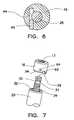
- FIG. 6is an enlarged sectional view of an end portion of the resilient spinal rod with controllable angulation of FIG. 1 taken along line 1 - 1 thereof;
- FIG. 7is a partial view of an end of the resilient spinal rod with controllable angulation of FIG. 1 showing an end cap thereof in exploded view;
- FIG. 8is a side view of the resilient spinal rod with controllable angulation of FIG. 1 in a lordosed, bent or curved position.
- a resilient spinal rod/rod system with controllable angulation (bending or curving) 10(generally, spinal rod 10 ), fashioned in accordance with the present principles and especially for use in a spinal stabilization system or assembly.
- the spinal rod 10is designed to be retained at both ends to respective bone anchoring elements (not shown) such as are known in the art.
- the spinal rod 10is fashioned from a biocompatible material such as titanium, stainless steel or the like.
- the spinal rod 10is characterized by a rod tube or cylinder 12 that surrounds a portion of a spring rod 14 .
- the rod tube 12is preferably, but not necessarily, formed by first and second rod tube portions 18 and 20 .
- the first and second rod tube portions 18 and 20each have a first end that is stepped or castled, i.e. ends 36 and 38 of respective first and second rod tube portions 18 and 20 , that are joined together at an approximate mid point or middle of the axial length of the spring rod 14 .
- the stepped first ends 36 and 38prevent and/or hinder rotation of the rod tube portions 18 and 20 relative to the spring rod 14 .
- the spring rod 14has a rod portion 26 that axially extends a length from a cylindrical head 24 .
- the rod portion 26extends through and within an axial bore 19 of the first rod tube portion 18 and an axial bore 21 of the second rod tube portion 20 .
- a second end 40 of the first tube portion 18abuts the cylindrical head 24 .
- the rod portion 26 of the spring rod 14terminates in an end 28 distal the cylindrical head 24 .
- the end 28has first external threading 29 and second external threading 31 separated by an annular groove 30 .
- the threaded end 28accepts an angulation ring 16 .
- the angulation ring 16includes an internally threaded bore 17 .
- the angulation ring 16is thus threadedly received onto the threaded end 28 .
- the angulation ring 16adjusts the curvature, bend or angulation of the spinal rod 10 .
- the spinal rod 10includes an essentially tubular spacer ring 46 that radially surrounds the rod portion 26 .
- the spacer ring 46is preferably, but not necessarily, made from titanium and is situated about the rod portion 26 at the middle or mid point of the length of the rod portion 26 , and particularly, radially inward of the first ends 36 and 38 of the first and second rod portions 18 and 20 . It should be appreciated that the spacer ring 46 may be provided at different places along the rod portion 26 and/or more than one spacer ring 46 may be provided. The spacer ring 46 prevents and/or hinders over angulation of the spinal rod 10 .
- the spinal rod 10also includes one or more (here, four) essentially tubular spacer rings 50 that radially surround the rod portion 26 .
- Theseare shown and described as polycarbonate urethane (PCU) spacer rings but may be of a different material and of different durometers
- PCUpolycarbonate urethane
- a spinal rod fashioned in accordance with the present principlesmay have more or less than four PCU spacer rings 50 or no spacer rings. In the case of no spacer rings, titanium spacers or wire cuts or other material washers may be used for the spring effect.
- Two of the four PCU spacer rings 50are positioned to one axial side of the spacer ring 46 while the other two of the four PCU spacer rings 50 are positioned to the other axial side of the spacer ring 46 .
- Axial positioning of the PCU spacer rings 50may be changed as desired.
- the PCU spacer rings 50act as an additional spring force in bending and as a shock absorber in axial compression of the spinal rod 10 . It should be appreciated that the spacer ring 26 may be used without the PCU spacer rings 50 , while the PCU spacer rings 50 may be used without the spacer ring 26 .
- the spacer ring 50includes a generally tubular body 52 have a central bore 60 extending from one tapered end 56 to another tapered end 58 .
- the body 52includes a curved outer periphery or wall 54 that radially inwardly arches from the tapered ends 56 and 58 towards a midpoint 53 .
- the curved outer wall 54controls collapse of the PCU spacer ring 50 during angulation.
- the PCU spacer rings 50may be made of various durometers to provide an additional spring force in bending and as a shock absorber in axial compression of the rod.
- the first rod portion 18includes an enlarged bore portion 48 that is greater in diameter than the diameter of the bore 19 of the first rod portion 18 .
- the second rod portion 20includes an enlarged bore portion 49 that is greater in diameter than the diameter of the bore 21 of the second rod portion 20 .
- the axial length of each enlarged bore portion 18 , 20is dependent on the number of spacer rings that the rod portions are to accommodate.
- FIGS. 6 and 7there is shown an enlarged sectional view of the end cap 16 and end structure 28 of the spinal rod 10 and an exploded view of the end cap 16 and end cap pin 66 relative to the end structure 28 respectively, of the spinal rod 10 .
- the end cap pin 66is positioned in or pressed into an end cap bore 64 of the end cap 16 such that the end cap pin 66 abuts the threads or pin groove 29 of the end structure 28 .
- the end cap pin 66thus prevents the end cap 16 from increasing or decreasing the angulation of the spinal rod 10 .
- FIG. 8depicts the spinal rod 10 in an angulated, bent or curved position.
- the end cap 16has been threaded onto the end structure 28 .
- the second rod portion 20axially compresses or pushes against the first rod portion 18 .
- the end 40 of the first rod portion 18axially compresses or pushes against the end 42 of the head 24 of the rod portion 26 .
- the spring tension of the rod portion 26 as well as the spring tension of the PCU spacer rings 50cause the spinal rod 10 to want to spring back to its original, uncompressed position.
- the angulation and/or the degree of angulation of the spinal rod 10may be accomplished and/or set during manufacture of the spinal rod. Alternatively, the angulation and/or degree of angulation of the spinal rod 10 may be accomplished in situ. The spinal rod 10 may be made in different lengths.
Landscapes
- Health & Medical Sciences (AREA)
- Orthopedic Medicine & Surgery (AREA)
- Life Sciences & Earth Sciences (AREA)
- Neurology (AREA)
- Surgery (AREA)
- Heart & Thoracic Surgery (AREA)
- Engineering & Computer Science (AREA)
- Biomedical Technology (AREA)
- Nuclear Medicine, Radiotherapy & Molecular Imaging (AREA)
- Medical Informatics (AREA)
- Molecular Biology (AREA)
- Animal Behavior & Ethology (AREA)
- General Health & Medical Sciences (AREA)
- Public Health (AREA)
- Veterinary Medicine (AREA)
- Surgical Instruments (AREA)
Abstract
Description
Claims (25)
Priority Applications (1)
| Application Number | Priority Date | Filing Date | Title |
|---|---|---|---|
| US12/196,438US8172879B2 (en) | 2007-08-23 | 2008-08-22 | Resilient spinal rod system with controllable angulation |
Applications Claiming Priority (2)
| Application Number | Priority Date | Filing Date | Title |
|---|---|---|---|
| US96597107P | 2007-08-23 | 2007-08-23 | |
| US12/196,438US8172879B2 (en) | 2007-08-23 | 2008-08-22 | Resilient spinal rod system with controllable angulation |
Publications (2)
| Publication Number | Publication Date |
|---|---|
| US20090054932A1 US20090054932A1 (en) | 2009-02-26 |
| US8172879B2true US8172879B2 (en) | 2012-05-08 |
Family
ID=40378683
Family Applications (1)
| Application Number | Title | Priority Date | Filing Date |
|---|---|---|---|
| US12/196,438Active2030-01-31US8172879B2 (en) | 2007-08-23 | 2008-08-22 | Resilient spinal rod system with controllable angulation |
Country Status (2)
| Country | Link |
|---|---|
| US (1) | US8172879B2 (en) |
| WO (1) | WO2009026519A1 (en) |
Cited By (14)
| Publication number | Priority date | Publication date | Assignee | Title |
|---|---|---|---|---|
| US20100318130A1 (en)* | 2007-12-15 | 2010-12-16 | Parlato Brian D | Flexible rod assembly for spinal fixation |
| US20120109207A1 (en)* | 2010-10-29 | 2012-05-03 | Warsaw Orthopedic, Inc. | Enhanced Interfacial Conformance for a Composite Rod for Spinal Implant Systems with Higher Modulus Core and Lower Modulus Polymeric Sleeve |
| US20130041469A1 (en)* | 2011-08-11 | 2013-02-14 | Jeff Phelps | Interbody axis cage |
| US20130090690A1 (en)* | 2011-10-06 | 2013-04-11 | David A. Walsh | Dynamic Rod Assembly |
| US10238432B2 (en) | 2017-02-10 | 2019-03-26 | Medos International Sàrl | Tandem rod connectors and related methods |
| US10321939B2 (en) | 2016-05-18 | 2019-06-18 | Medos International Sarl | Implant connectors and related methods |
| US10398476B2 (en) | 2016-12-13 | 2019-09-03 | Medos International Sàrl | Implant adapters and related methods |
| US10492835B2 (en) | 2016-12-19 | 2019-12-03 | Medos International Sàrl | Offset rods, offset rod connectors, and related methods |
| US10517647B2 (en) | 2016-05-18 | 2019-12-31 | Medos International Sarl | Implant connectors and related methods |
| US10561454B2 (en) | 2017-03-28 | 2020-02-18 | Medos International Sarl | Articulating implant connectors and related methods |
| US10966761B2 (en) | 2017-03-28 | 2021-04-06 | Medos International Sarl | Articulating implant connectors and related methods |
| US11076890B2 (en) | 2017-12-01 | 2021-08-03 | Medos International Sàrl | Rod-to-rod connectors having robust rod closure mechanisms and related methods |
| US20230085446A1 (en)* | 2007-06-22 | 2023-03-16 | Empirical Spine, Inc, | Methods and systems for increasing the bending stiffness of a spinal segment with elongation limit |
| RU2810365C1 (en)* | 2023-04-28 | 2023-12-27 | Общество с ограниченной ответственностью "КОНМЕТ" | Tool for bending bars during transpedicular fixation |
Families Citing this family (49)
| Publication number | Priority date | Publication date | Assignee | Title |
|---|---|---|---|---|
| US8292926B2 (en) | 2005-09-30 | 2012-10-23 | Jackson Roger P | Dynamic stabilization connecting member with elastic core and outer sleeve |
| US10258382B2 (en)* | 2007-01-18 | 2019-04-16 | Roger P. Jackson | Rod-cord dynamic connection assemblies with slidable bone anchor attachment members along the cord |
| US20160242816A9 (en) | 2001-05-09 | 2016-08-25 | Roger P. Jackson | Dynamic spinal stabilization assembly with elastic bumpers and locking limited travel closure mechanisms |
| US10729469B2 (en) | 2006-01-09 | 2020-08-04 | Roger P. Jackson | Flexible spinal stabilization assembly with spacer having off-axis core member |
| US7862587B2 (en) | 2004-02-27 | 2011-01-04 | Jackson Roger P | Dynamic stabilization assemblies, tool set and method |
| US8353932B2 (en)* | 2005-09-30 | 2013-01-15 | Jackson Roger P | Polyaxial bone anchor assembly with one-piece closure, pressure insert and plastic elongate member |
| US7621918B2 (en) | 2004-11-23 | 2009-11-24 | Jackson Roger P | Spinal fixation tool set and method |
| US7766915B2 (en) | 2004-02-27 | 2010-08-03 | Jackson Roger P | Dynamic fixation assemblies with inner core and outer coil-like member |
| US8092500B2 (en) | 2007-05-01 | 2012-01-10 | Jackson Roger P | Dynamic stabilization connecting member with floating core, compression spacer and over-mold |
| US7776067B2 (en) | 2005-05-27 | 2010-08-17 | Jackson Roger P | Polyaxial bone screw with shank articulation pressure insert and method |
| US11419642B2 (en) | 2003-12-16 | 2022-08-23 | Medos International Sarl | Percutaneous access devices and bone anchor assemblies |
| US7527638B2 (en) | 2003-12-16 | 2009-05-05 | Depuy Spine, Inc. | Methods and devices for minimally invasive spinal fixation element placement |
| US7179261B2 (en) | 2003-12-16 | 2007-02-20 | Depuy Spine, Inc. | Percutaneous access devices and bone anchor assemblies |
| JP2007525274A (en) | 2004-02-27 | 2007-09-06 | ロジャー・ピー・ジャクソン | Orthopedic implant rod reduction instrument set and method |
| US11241261B2 (en) | 2005-09-30 | 2022-02-08 | Roger P Jackson | Apparatus and method for soft spinal stabilization using a tensionable cord and releasable end structure |
| US8152810B2 (en) | 2004-11-23 | 2012-04-10 | Jackson Roger P | Spinal fixation tool set and method |
| US7160300B2 (en) | 2004-02-27 | 2007-01-09 | Jackson Roger P | Orthopedic implant rod reduction tool set and method |
| US7651502B2 (en) | 2004-09-24 | 2010-01-26 | Jackson Roger P | Spinal fixation tool set and method for rod reduction and fastener insertion |
| US9216041B2 (en) | 2009-06-15 | 2015-12-22 | Roger P. Jackson | Spinal connecting members with tensioned cords and rigid sleeves for engaging compression inserts |
| WO2006057837A1 (en) | 2004-11-23 | 2006-06-01 | Jackson Roger P | Spinal fixation tool attachment structure |
| US7901437B2 (en) | 2007-01-26 | 2011-03-08 | Jackson Roger P | Dynamic stabilization member with molded connection |
| US8105368B2 (en) | 2005-09-30 | 2012-01-31 | Jackson Roger P | Dynamic stabilization connecting member with slitted core and outer sleeve |
| US20080140076A1 (en)* | 2005-09-30 | 2008-06-12 | Jackson Roger P | Dynamic stabilization connecting member with slitted segment and surrounding external elastomer |
| WO2007061960A2 (en) | 2005-11-18 | 2007-05-31 | Life Spine, Inc. | Dynamic spinal stabilization devices and systems |
| US7815663B2 (en)* | 2006-01-27 | 2010-10-19 | Warsaw Orthopedic, Inc. | Vertebral rods and methods of use |
| CA2670988C (en) | 2006-12-08 | 2014-03-25 | Roger P. Jackson | Tool system for dynamic spinal implants |
| US11224463B2 (en) | 2007-01-18 | 2022-01-18 | Roger P. Jackson | Dynamic stabilization connecting member with pre-tensioned flexible core member |
| US8475498B2 (en)* | 2007-01-18 | 2013-07-02 | Roger P. Jackson | Dynamic stabilization connecting member with cord connection |
| US8366745B2 (en)* | 2007-05-01 | 2013-02-05 | Jackson Roger P | Dynamic stabilization assembly having pre-compressed spacers with differential displacements |
| US8012177B2 (en) | 2007-02-12 | 2011-09-06 | Jackson Roger P | Dynamic stabilization assembly with frusto-conical connection |
| US8979904B2 (en) | 2007-05-01 | 2015-03-17 | Roger P Jackson | Connecting member with tensioned cord, low profile rigid sleeve and spacer with torsion control |
| US10383660B2 (en) | 2007-05-01 | 2019-08-20 | Roger P. Jackson | Soft stabilization assemblies with pretensioned cords |
| WO2009026519A1 (en) | 2007-08-23 | 2009-02-26 | Life Spine Inc. | Resilient spinal rod system with controllable angulation |
| US20090088782A1 (en)* | 2007-09-28 | 2009-04-02 | Missoum Moumene | Flexible Spinal Rod With Elastomeric Jacket |
| AU2010260521C1 (en) | 2008-08-01 | 2013-08-01 | Roger P. Jackson | Longitudinal connecting member with sleeved tensioned cords |
| EP2160988B1 (en)* | 2008-09-04 | 2012-12-26 | Biedermann Technologies GmbH & Co. KG | Rod-shaped implant in particular for stabilizing the spinal column and stabilization device including such a rod-shaped implant |
| EP2376008A1 (en)* | 2008-12-22 | 2011-10-19 | Synthes GmbH | Variable tension spine fixation rod |
| US8118840B2 (en) | 2009-02-27 | 2012-02-21 | Warsaw Orthopedic, Inc. | Vertebral rod and related method of manufacture |
| US9668771B2 (en) | 2009-06-15 | 2017-06-06 | Roger P Jackson | Soft stabilization assemblies with off-set connector |
| US9011494B2 (en)* | 2009-09-24 | 2015-04-21 | Warsaw Orthopedic, Inc. | Composite vertebral rod system and methods of use |
| EP2485654B1 (en) | 2009-10-05 | 2021-05-05 | Jackson P. Roger | Polyaxial bone anchor with non-pivotable retainer and pop-on shank, some with friction fit |
| WO2011066231A1 (en)* | 2009-11-25 | 2011-06-03 | Seaspine, Inc. | Hybrid rod constructs for spinal applications |
| US8317834B2 (en)* | 2010-01-28 | 2012-11-27 | Warsaw Orthopedic, Inc. | Pre-assembled construct for insertion into a patient |
| US20120029564A1 (en)* | 2010-07-29 | 2012-02-02 | Warsaw Orthopedic, Inc. | Composite Rod for Spinal Implant Systems With Higher Modulus Core and Lower Modulus Polymeric Sleeve |
| AU2011299558A1 (en) | 2010-09-08 | 2013-05-02 | Roger P. Jackson | Dynamic stabilization members with elastic and inelastic sections |
| US20120277798A1 (en)* | 2011-04-28 | 2012-11-01 | Warsaw Orthopedic, Inc. | Spinal Rod Construct to Limit Facet Impingement |
| US10588642B2 (en) | 2014-05-15 | 2020-03-17 | Gauthier Biomedical, Inc. | Molding process and products formed thereby |
| WO2020178838A1 (en)* | 2019-03-07 | 2020-09-10 | Carbofix In Orthopedics Llc | Devices, assemblies, kits, systems and methods for shaping of elongated elements containing thermoplastic polymers |
| US12434426B2 (en) | 2023-12-11 | 2025-10-07 | Carbofix Spine Inc | Device for maintaining the shape of cross-sectional profile of an elongated element including composite material, and a device for bending thereof |
Citations (29)
| Publication number | Priority date | Publication date | Assignee | Title |
|---|---|---|---|---|
| US4041939A (en)* | 1975-04-28 | 1977-08-16 | Downs Surgical Limited | Surgical implant spinal screw |
| US4804000A (en) | 1987-01-21 | 1989-02-14 | Steve Lamb | Dynamic sagittal knee test apparatus |
| US5034011A (en) | 1990-08-09 | 1991-07-23 | Advanced Spine Fixation Systems Incorporated | Segmental instrumentation of the posterior spine |
| US5047029A (en) | 1988-06-10 | 1991-09-10 | Synthes (U.S.A.) | Clamp and system for internal fixation |
| FR2715825A1 (en) | 1994-02-09 | 1995-08-11 | Soprane Sa | Self-aligning rod for spinal osteosynthesis apparatus |
| US5466238A (en) | 1993-08-27 | 1995-11-14 | Lin; Chih-I | Vertebral locking and retrieving system having a fixation crossbar |
| US6241730B1 (en) | 1997-11-26 | 2001-06-05 | Scient'x (Societe A Responsabilite Limitee) | Intervertebral link device capable of axial and angular displacement |
| US6290700B1 (en) | 1997-07-31 | 2001-09-18 | Plus Endoprothetik Ag | Device for stiffening and/or correcting a vertebral column or such like |
| US20040039384A1 (en) | 2002-08-21 | 2004-02-26 | Boehm Frank H. | Device and method for pertcutaneous placement of lumbar pedicle screws and connecting rods |
| US6736818B2 (en) | 1999-11-11 | 2004-05-18 | Synthes (U.S.A.) | Radially expandable intramedullary nail |
| US20050038432A1 (en) | 2003-04-25 | 2005-02-17 | Shaolian Samuel M. | Articulating spinal fixation rod and system |
| US20050065514A1 (en) | 2001-12-07 | 2005-03-24 | Armin Studer | Damping element |
| US20050085815A1 (en) | 2003-10-17 | 2005-04-21 | Biedermann Motech Gmbh | Rod-shaped implant element for application in spine surgery or trauma surgery, stabilization apparatus comprising said rod-shaped implant element, and production method for the rod-shaped implant element |
| US20050113927A1 (en) | 2003-11-25 | 2005-05-26 | Malek Michel H. | Spinal stabilization systems |
| US20050124991A1 (en) | 2003-12-05 | 2005-06-09 | Tae-Ahn Jahng | Method and apparatus for flexible fixation of a spine |
| US20050131407A1 (en) | 2003-12-16 | 2005-06-16 | Sicvol Christopher W. | Flexible spinal fixation elements |
| US20050143823A1 (en) | 2003-12-31 | 2005-06-30 | Boyd Lawrence M. | Dynamic spinal stabilization system |
| US20050165396A1 (en) | 2001-07-18 | 2005-07-28 | Frederic Fortin | Flexible vertebral linking device |
| US20050182409A1 (en) | 2003-05-02 | 2005-08-18 | Ronald Callahan | Systems and methods accommodating relative motion in spine stabilization |
| US20050222569A1 (en) | 2003-05-02 | 2005-10-06 | Panjabi Manohar M | Dynamic spine stabilizer |
| US20060106381A1 (en) | 2004-11-18 | 2006-05-18 | Ferree Bret A | Methods and apparatus for treating spinal stenosis |
| US20060229612A1 (en) | 2005-03-03 | 2006-10-12 | Accin Corporation | Methods and apparatus for vertebral stabilization using sleeved springs |
| US20060264937A1 (en) | 2005-05-04 | 2006-11-23 | White Patrick M | Mobile spine stabilization device |
| US20060264935A1 (en) | 2005-05-04 | 2006-11-23 | White Patrick M | Orthopedic stabilization device |
| US20070118122A1 (en) | 2005-11-18 | 2007-05-24 | Life Spine, Llc | Dynamic spinal stabilization device and systems |
| US7326210B2 (en) | 2003-09-24 | 2008-02-05 | N Spine, Inc | Spinal stabilization device |
| WO2009026519A1 (en) | 2007-08-23 | 2009-02-26 | Life Spine Inc. | Resilient spinal rod system with controllable angulation |
| US7621940B2 (en) | 2004-03-09 | 2009-11-24 | Biedermann Motech Gmbh | Rod-like element for application in spinal or trauma surgery, and stabilization device with such a rod-like element |
| US7815665B2 (en)* | 2003-09-24 | 2010-10-19 | N Spine, Inc. | Adjustable spinal stabilization system |
Family Cites Families (1)
| Publication number | Priority date | Publication date | Assignee | Title |
|---|---|---|---|---|
| US6738818B1 (en)* | 1999-12-27 | 2004-05-18 | Intel Corporation | Centralized technique for assigning I/O controllers to hosts in a cluster |
- 2008
- 2008-08-22WOPCT/US2008/074019patent/WO2009026519A1/enactiveSearch and Examination
- 2008-08-22USUS12/196,438patent/US8172879B2/enactiveActive
Patent Citations (30)
| Publication number | Priority date | Publication date | Assignee | Title |
|---|---|---|---|---|
| US4041939A (en)* | 1975-04-28 | 1977-08-16 | Downs Surgical Limited | Surgical implant spinal screw |
| US4804000A (en) | 1987-01-21 | 1989-02-14 | Steve Lamb | Dynamic sagittal knee test apparatus |
| US5047029A (en) | 1988-06-10 | 1991-09-10 | Synthes (U.S.A.) | Clamp and system for internal fixation |
| US5034011A (en) | 1990-08-09 | 1991-07-23 | Advanced Spine Fixation Systems Incorporated | Segmental instrumentation of the posterior spine |
| US5466238A (en) | 1993-08-27 | 1995-11-14 | Lin; Chih-I | Vertebral locking and retrieving system having a fixation crossbar |
| FR2715825A1 (en) | 1994-02-09 | 1995-08-11 | Soprane Sa | Self-aligning rod for spinal osteosynthesis apparatus |
| US6290700B1 (en) | 1997-07-31 | 2001-09-18 | Plus Endoprothetik Ag | Device for stiffening and/or correcting a vertebral column or such like |
| US6241730B1 (en) | 1997-11-26 | 2001-06-05 | Scient'x (Societe A Responsabilite Limitee) | Intervertebral link device capable of axial and angular displacement |
| US6736818B2 (en) | 1999-11-11 | 2004-05-18 | Synthes (U.S.A.) | Radially expandable intramedullary nail |
| US20050165396A1 (en) | 2001-07-18 | 2005-07-28 | Frederic Fortin | Flexible vertebral linking device |
| US20050065514A1 (en) | 2001-12-07 | 2005-03-24 | Armin Studer | Damping element |
| US20040039384A1 (en) | 2002-08-21 | 2004-02-26 | Boehm Frank H. | Device and method for pertcutaneous placement of lumbar pedicle screws and connecting rods |
| US20050038432A1 (en) | 2003-04-25 | 2005-02-17 | Shaolian Samuel M. | Articulating spinal fixation rod and system |
| US20050222569A1 (en) | 2003-05-02 | 2005-10-06 | Panjabi Manohar M | Dynamic spine stabilizer |
| US20050182409A1 (en) | 2003-05-02 | 2005-08-18 | Ronald Callahan | Systems and methods accommodating relative motion in spine stabilization |
| US7815665B2 (en)* | 2003-09-24 | 2010-10-19 | N Spine, Inc. | Adjustable spinal stabilization system |
| US7326210B2 (en) | 2003-09-24 | 2008-02-05 | N Spine, Inc | Spinal stabilization device |
| US20050085815A1 (en) | 2003-10-17 | 2005-04-21 | Biedermann Motech Gmbh | Rod-shaped implant element for application in spine surgery or trauma surgery, stabilization apparatus comprising said rod-shaped implant element, and production method for the rod-shaped implant element |
| US20050113927A1 (en) | 2003-11-25 | 2005-05-26 | Malek Michel H. | Spinal stabilization systems |
| US20050124991A1 (en) | 2003-12-05 | 2005-06-09 | Tae-Ahn Jahng | Method and apparatus for flexible fixation of a spine |
| US20050131407A1 (en) | 2003-12-16 | 2005-06-16 | Sicvol Christopher W. | Flexible spinal fixation elements |
| US20050143823A1 (en) | 2003-12-31 | 2005-06-30 | Boyd Lawrence M. | Dynamic spinal stabilization system |
| US7621940B2 (en) | 2004-03-09 | 2009-11-24 | Biedermann Motech Gmbh | Rod-like element for application in spinal or trauma surgery, and stabilization device with such a rod-like element |
| US20060106381A1 (en) | 2004-11-18 | 2006-05-18 | Ferree Bret A | Methods and apparatus for treating spinal stenosis |
| US20060229612A1 (en) | 2005-03-03 | 2006-10-12 | Accin Corporation | Methods and apparatus for vertebral stabilization using sleeved springs |
| US7556639B2 (en) | 2005-03-03 | 2009-07-07 | Accelerated Innovation, Llc | Methods and apparatus for vertebral stabilization using sleeved springs |
| US20060264937A1 (en) | 2005-05-04 | 2006-11-23 | White Patrick M | Mobile spine stabilization device |
| US20060264935A1 (en) | 2005-05-04 | 2006-11-23 | White Patrick M | Orthopedic stabilization device |
| US20070118122A1 (en) | 2005-11-18 | 2007-05-24 | Life Spine, Llc | Dynamic spinal stabilization device and systems |
| WO2009026519A1 (en) | 2007-08-23 | 2009-02-26 | Life Spine Inc. | Resilient spinal rod system with controllable angulation |
Non-Patent Citations (1)
| Title |
|---|
| Written Opinion of the International Searching Authority for PCT Application No. PCT/US08/74019, mail date Nov. 3, 2008, 4 pages. |
Cited By (24)
| Publication number | Priority date | Publication date | Assignee | Title |
|---|---|---|---|---|
| US20230085446A1 (en)* | 2007-06-22 | 2023-03-16 | Empirical Spine, Inc, | Methods and systems for increasing the bending stiffness of a spinal segment with elongation limit |
| US20100318130A1 (en)* | 2007-12-15 | 2010-12-16 | Parlato Brian D | Flexible rod assembly for spinal fixation |
| US20120109207A1 (en)* | 2010-10-29 | 2012-05-03 | Warsaw Orthopedic, Inc. | Enhanced Interfacial Conformance for a Composite Rod for Spinal Implant Systems with Higher Modulus Core and Lower Modulus Polymeric Sleeve |
| US20130041469A1 (en)* | 2011-08-11 | 2013-02-14 | Jeff Phelps | Interbody axis cage |
| US9144506B2 (en)* | 2011-08-11 | 2015-09-29 | Jeff Phelps | Interbody axis cage |
| US20130090690A1 (en)* | 2011-10-06 | 2013-04-11 | David A. Walsh | Dynamic Rod Assembly |
| US10321939B2 (en) | 2016-05-18 | 2019-06-18 | Medos International Sarl | Implant connectors and related methods |
| US10517647B2 (en) | 2016-05-18 | 2019-12-31 | Medos International Sarl | Implant connectors and related methods |
| US11596451B2 (en) | 2016-05-18 | 2023-03-07 | Medos International Sarl | Implant connectors and related methods |
| US11058463B2 (en) | 2016-05-18 | 2021-07-13 | Medos International Sarl | Implant connectors and related methods |
| US10398476B2 (en) | 2016-12-13 | 2019-09-03 | Medos International Sàrl | Implant adapters and related methods |
| US11160583B2 (en) | 2016-12-19 | 2021-11-02 | Medos International Sarl | Offset rods, offset rod connectors, and related methods |
| US10492835B2 (en) | 2016-12-19 | 2019-12-03 | Medos International Sàrl | Offset rods, offset rod connectors, and related methods |
| US12150679B2 (en) | 2016-12-19 | 2024-11-26 | Medos International Srl | Offset rods, offset rod connectors, and related methods |
| US10869695B2 (en) | 2017-02-10 | 2020-12-22 | Medos International Sarl | Tandem rod connectors and related methods |
| US10238432B2 (en) | 2017-02-10 | 2019-03-26 | Medos International Sàrl | Tandem rod connectors and related methods |
| US11793554B2 (en) | 2017-02-10 | 2023-10-24 | Medos International Sarl | Tandem rod connectors and related methods |
| US11382676B2 (en) | 2017-03-28 | 2022-07-12 | Medos International Sarl | Articulating implant connectors and related methods |
| US10966761B2 (en) | 2017-03-28 | 2021-04-06 | Medos International Sarl | Articulating implant connectors and related methods |
| US11707304B2 (en) | 2017-03-28 | 2023-07-25 | Medos International Sarl | Articulating implant connectors and related methods |
| US12059187B2 (en) | 2017-03-28 | 2024-08-13 | Medos International Sarl | Articulating implant connectors and related methods |
| US10561454B2 (en) | 2017-03-28 | 2020-02-18 | Medos International Sarl | Articulating implant connectors and related methods |
| US11076890B2 (en) | 2017-12-01 | 2021-08-03 | Medos International Sàrl | Rod-to-rod connectors having robust rod closure mechanisms and related methods |
| RU2810365C1 (en)* | 2023-04-28 | 2023-12-27 | Общество с ограниченной ответственностью "КОНМЕТ" | Tool for bending bars during transpedicular fixation |
Also Published As
| Publication number | Publication date |
|---|---|
| US20090054932A1 (en) | 2009-02-26 |
| WO2009026519A1 (en) | 2009-02-26 |
Similar Documents
| Publication | Publication Date | Title |
|---|---|---|
| US8172879B2 (en) | Resilient spinal rod system with controllable angulation | |
| US8221467B2 (en) | Dynamic spinal stabilization device and systems | |
| US11389211B2 (en) | Polyaxial screwdriver for a pedicle screw system | |
| US8657856B2 (en) | Size transition spinal rod | |
| EP2451369B1 (en) | Vertebral stabilization transition connector | |
| US9504497B2 (en) | Iliosacral polyaxial screw | |
| EP3409225B1 (en) | Vertebral stabilization system | |
| US20060212033A1 (en) | Vertebral stabilization using flexible rods | |
| US8439923B2 (en) | Poly-axial pedicle screw assembly | |
| US20060229612A1 (en) | Methods and apparatus for vertebral stabilization using sleeved springs | |
| US20140277146A1 (en) | Cross-braced bilateral spinal rod connector | |
| US8979906B2 (en) | Spine rod clamping body and pedicle screw assembly comprising same |
Legal Events
| Date | Code | Title | Description |
|---|---|---|---|
| AS | Assignment | Owner name:SILICON VALLEY BANK, COLORADO Free format text:SECURITY AGREEMENT;ASSIGNOR:LIFE SPINE, INC.;REEL/FRAME:025846/0010 Effective date:20110208 | |
| AS | Assignment | Owner name:LIFE SPINE, INC., ILLINOIS Free format text:RELEASE BY SECURED PARTY;ASSIGNOR:SILICON VALLEY BANK;REEL/FRAME:026944/0931 Effective date:20110920 | |
| AS | Assignment | Owner name:LIFE SPINE, INC., ILLINOIS Free format text:ASSIGNMENT OF ASSIGNORS INTEREST;ASSIGNORS:BUTLER, MICHAEL S.;HARTSELL, BRIAN D.;REEL/FRAME:028018/0465 Effective date:20080916 | |
| STCF | Information on status: patent grant | Free format text:PATENTED CASE | |
| AS | Assignment | Owner name:BMO HARRIS BANK N.A., ILLINOIS Free format text:SECURITY INTEREST;ASSIGNOR:LIFE SPINE, INC.;REEL/FRAME:033276/0408 Effective date:20140626 | |
| FPAY | Fee payment | Year of fee payment:4 | |
| AS | Assignment | Owner name:MB FINANCIAL BANK, N.A., ILLINOIS Free format text:SECURITY INTEREST;ASSIGNORS:LIFE SPINE, INC.;GIZMO MEDICAL, LLC;REEL/FRAME:040491/0791 Effective date:20161025 Owner name:ST CLOUD CAPITAL PARTNERS III SBIC, LP, CALIFORNIA Free format text:SECURITY INTEREST;ASSIGNORS:GIZMO MEDICAL, LLC;LIFE SPINE, INC.;REEL/FRAME:040497/0926 Effective date:20161025 | |
| AS | Assignment | Owner name:LIFE SPINE, INC., ILLINOIS Free format text:RELEASE BY SECURED PARTY;ASSIGNOR:BMO HARRIS BANK N.A.;REEL/FRAME:040511/0788 Effective date:20161028 | |
| AS | Assignment | Owner name:ST CLOUD CAPITAL PARTNERS III SBIC, LP, CALIFORNIA Free format text:CORRECTIVE ASSIGNMENT TO CORRECT THE LEGAL DOCUMENT ATTACHED TO THE FILING PREVIOUSLY RECORDED AT REEL: 040497 FRAME: 0926. ASSIGNOR(S) HEREBY CONFIRMS THE SECURITY INTEREST;ASSIGNORS:GIZMO MEDIACL, LLC;LIFE SPINE, INC.;REEL/FRAME:042084/0917 Effective date:20161025 Owner name:ST CLOUD CAPITAL PARTNERS III SBIC, LP, CALIFORNIA Free format text:CORRECTIVE ASSIGNMENT TO CORRECT THE LEGAL DOCUMENT PREVIOUSLY RECORDED AT REEL: 040497 FRAME: 0926. ASSIGNOR(S) HEREBY CONFIRMS THE ASSIGNMENT;ASSIGNORS:GIZMO MEDICAL, LLC;LIFE SPINE, INC.;REEL/FRAME:042243/0607 Effective date:20161025 | |
| FEPP | Fee payment procedure | Free format text:MAINTENANCE FEE REMINDER MAILED (ORIGINAL EVENT CODE: REM.); ENTITY STATUS OF PATENT OWNER: SMALL ENTITY | |
| FEPP | Fee payment procedure | Free format text:7.5 YR SURCHARGE - LATE PMT W/IN 6 MO, SMALL ENTITY (ORIGINAL EVENT CODE: M2555); ENTITY STATUS OF PATENT OWNER: SMALL ENTITY | |
| MAFP | Maintenance fee payment | Free format text:PAYMENT OF MAINTENANCE FEE, 8TH YR, SMALL ENTITY (ORIGINAL EVENT CODE: M2552); ENTITY STATUS OF PATENT OWNER: SMALL ENTITY Year of fee payment:8 | |
| AS | Assignment | Owner name:GIZMO MEDICAL, LLC, ILLINOIS Free format text:RELEASE BY SECURED PARTY;ASSIGNOR:FIFTH THIRD BANK, NATIONAL ASSOCIATION;REEL/FRAME:054843/0755 Effective date:20201218 Owner name:LIFE SPINE, INC., ILLINOIS Free format text:RELEASE BY SECURED PARTY;ASSIGNOR:FIFTH THIRD BANK, NATIONAL ASSOCIATION;REEL/FRAME:054843/0755 Effective date:20201218 Owner name:ST. CLOUD CAPITAL PARTNERS III SBIC, LP, CALIFORNIA Free format text:SECURITY INTEREST;ASSIGNORS:LIFE SPINE, INC.;GIZMO MEDICAL, LLC;REEL/FRAME:054844/0239 Effective date:20201218 | |
| AS | Assignment | Owner name:ASSOCIATED BANK, NATIONAL ASSOCIATION, AS AGENT, ILLINOIS Free format text:SECURITY INTEREST;ASSIGNOR:LIFE SPINE, INC.;REEL/FRAME:056728/0438 Effective date:20210630 | |
| AS | Assignment | Owner name:LIFE SPINE, INC., ILLINOIS Free format text:RELEASE BY SECURED PARTY;ASSIGNOR:ASSOCIATED BANK, NATIONAL ASSOCIATION;REEL/FRAME:064275/0446 Effective date:20230526 | |
| FEPP | Fee payment procedure | Free format text:MAINTENANCE FEE REMINDER MAILED (ORIGINAL EVENT CODE: REM.); ENTITY STATUS OF PATENT OWNER: SMALL ENTITY | |
| FEPP | Fee payment procedure | Free format text:11.5 YR SURCHARGE- LATE PMT W/IN 6 MO, SMALL ENTITY (ORIGINAL EVENT CODE: M2556); ENTITY STATUS OF PATENT OWNER: SMALL ENTITY | |
| MAFP | Maintenance fee payment | Free format text:PAYMENT OF MAINTENANCE FEE, 12TH YR, SMALL ENTITY (ORIGINAL EVENT CODE: M2553); ENTITY STATUS OF PATENT OWNER: SMALL ENTITY Year of fee payment:12 |