US8172878B2 - Conical interspinous apparatus and a method of performing interspinous distraction - Google Patents
Conical interspinous apparatus and a method of performing interspinous distractionDownload PDFInfo
- Publication number
- US8172878B2 US8172878B2US12/343,082US34308208AUS8172878B2US 8172878 B2US8172878 B2US 8172878B2US 34308208 AUS34308208 AUS 34308208AUS 8172878 B2US8172878 B2US 8172878B2
- Authority
- US
- United States
- Prior art keywords
- distractor
- engagement groove
- spinous processes
- pair
- central engagement
- Prior art date
- Legal status (The legal status is an assumption and is not a legal conclusion. Google has not performed a legal analysis and makes no representation as to the accuracy of the status listed.)
- Expired - Fee Related, expires
Links
- 238000000034methodMethods0.000titleclaimsabstractdescription165
- 238000003780insertionMethods0.000claimsabstractdescription193
- 230000037431insertionEffects0.000claimsabstractdescription193
- 230000008569processEffects0.000claimsabstractdescription143
- 239000003381stabilizerSubstances0.000claimsabstractdescription39
- 230000006641stabilisationEffects0.000claimsdescription157
- 238000011105stabilizationMethods0.000claimsdescription157
- 230000007246mechanismEffects0.000claimsdescription16
- 239000004696Poly ether ether ketoneSubstances0.000claimsdescription13
- 229920002530polyetherether ketonePolymers0.000claimsdescription13
- 210000000988bone and boneAnatomy0.000claimsdescription12
- 229910052588hydroxylapatiteInorganic materials0.000claimsdescription12
- XYJRXVWERLGGKC-UHFFFAOYSA-Dpentacalcium;hydroxide;triphosphateChemical compound[OH-].[Ca+2].[Ca+2].[Ca+2].[Ca+2].[Ca+2].[O-]P([O-])([O-])=O.[O-]P([O-])([O-])=O.[O-]P([O-])([O-])=OXYJRXVWERLGGKC-UHFFFAOYSA-D0.000claimsdescription12
- 239000000463materialSubstances0.000claimsdescription10
- RTAQQCXQSZGOHL-UHFFFAOYSA-NTitaniumChemical compound[Ti]RTAQQCXQSZGOHL-UHFFFAOYSA-N0.000claimsdescription7
- 229910052719titaniumInorganic materials0.000claimsdescription7
- 239000010936titaniumSubstances0.000claimsdescription7
- 239000002639bone cementSubstances0.000claimsdescription6
- 239000000316bone substituteSubstances0.000claimsdescription6
- 239000010935stainless steelSubstances0.000claimsdescription6
- 229910001220stainless steelInorganic materials0.000claimsdescription6
- 230000006835compressionEffects0.000claimsdescription3
- 238000007906compressionMethods0.000claimsdescription3
- 230000008878couplingEffects0.000claimsdescription2
- 238000010168coupling processMethods0.000claimsdescription2
- 238000005859coupling reactionMethods0.000claimsdescription2
- 210000003041ligamentAnatomy0.000description12
- 208000005198spinal stenosisDiseases0.000description11
- 230000004927fusionEffects0.000description10
- 238000001356surgical procedureMethods0.000description5
- 206010025005lumbar spinal stenosisDiseases0.000description4
- 239000007787solidSubstances0.000description4
- 230000010339dilationEffects0.000description3
- 230000000694effectsEffects0.000description3
- 239000007943implantSubstances0.000description3
- 238000002684laminectomyMethods0.000description3
- 238000005096rolling processMethods0.000description3
- 238000010276constructionMethods0.000description2
- 210000004705lumbosacral regionAnatomy0.000description2
- 239000012056semi-solid materialSubstances0.000description2
- 239000011343solid materialSubstances0.000description2
- 230000000087stabilizing effectEffects0.000description2
- 208000003618Intervertebral Disc DisplacementDiseases0.000description1
- 208000008930Low Back PainDiseases0.000description1
- 206010028980NeoplasmDiseases0.000description1
- 208000001132OsteoporosisDiseases0.000description1
- 208000002193PainDiseases0.000description1
- 229910000831SteelInorganic materials0.000description1
- 230000002159abnormal effectEffects0.000description1
- 230000032683agingEffects0.000description1
- 229910045601alloyInorganic materials0.000description1
- 239000000956alloySubstances0.000description1
- 210000001217buttockAnatomy0.000description1
- 230000006837decompressionEffects0.000description1
- 230000003247decreasing effectEffects0.000description1
- 230000007850degenerationEffects0.000description1
- 210000002683footAnatomy0.000description1
- 230000006870functionEffects0.000description1
- 210000002414legAnatomy0.000description1
- 239000007788liquidSubstances0.000description1
- 238000012986modificationMethods0.000description1
- 230000004048modificationEffects0.000description1
- 230000035807sensationEffects0.000description1
- 210000000278spinal cordAnatomy0.000description1
- 210000001032spinal nerveAnatomy0.000description1
- 230000007480spreadingEffects0.000description1
- 239000010959steelSubstances0.000description1
- 208000024891symptomDiseases0.000description1
- 210000000689upper legAnatomy0.000description1
Images


Classifications
- A—HUMAN NECESSITIES
- A61—MEDICAL OR VETERINARY SCIENCE; HYGIENE
- A61B—DIAGNOSIS; SURGERY; IDENTIFICATION
- A61B17/00—Surgical instruments, devices or methods
- A61B17/56—Surgical instruments or methods for treatment of bones or joints; Devices specially adapted therefor
- A61B17/58—Surgical instruments or methods for treatment of bones or joints; Devices specially adapted therefor for osteosynthesis, e.g. bone plates, screws or setting implements
- A61B17/68—Internal fixation devices, including fasteners and spinal fixators, even if a part thereof projects from the skin
- A61B17/70—Spinal positioners or stabilisers, e.g. stabilisers comprising fluid filler in an implant
- A61B17/7062—Devices acting on, attached to, or simulating the effect of, vertebral processes, vertebral facets or ribs ; Tools for such devices
- A61B17/7065—Devices with changeable shape, e.g. collapsible or having retractable arms to aid implantation; Tools therefor
Definitions
- the present inventionrelates to the field of interspinous devices, and more particularly, relates to conical interspinous apparatus inserted between two spinous processes of the lumbar spine such that the two spinous processes are separated, the spinal canal opens and the symptoms of spinal stenosis are alleviated.
- the conical interspinous apparatuscan be used to treat spinal stenosis.
- Lumbar Spinal Stenosisis one of the most common reasons for spine surgery in older people.
- Spinal stenosisis a medical condition in which the spinal canal narrows and compresses the spinal cord and nerves. This is usually due to the natural process of spinal degeneration that occurs with aging. It can also sometimes be caused by spinal disc herniation, osteoporosis or a tumor.
- Spinal stenosismay affect the cervical or lumbar vertebrae or both.
- Lumbar spinal stenosisresults in lower back pain as well as pain or abnormal sensations in the legs, thighs, feet or buttocks, or loss of bladder and bowel control.
- Laminectomyis a basic part of the surgical treatment of LSS and is the most effective remedy for severe spinal stenosis. Laminectomy can be done without spinal fusion. However, if the spinal column is unstable, fusion may be required for the laminectomy.
- a device which can be implanted between two spinous processes of the spine more easily and which involves less invasive procedures than present day proceduresis needed. Also, a device which can easily be adapted for both fusion and non-fusion procedures is needed. Such a device would aid in the treatment for spinal stenosis.
- Exemplary embodiments of the present inventionovercome the above disadvantages and other disadvantages not described above. Also, the present invention is not required to overcome the disadvantages described above, and an exemplary embodiment of the present invention may not overcome any of the problems described above.
- the present inventionprovides conical interspinous apparatus inserted between two spinous processes of the lumbar spine such that the two spinous processes are separated, and a method of performing interspinous distraction.
- a conical interspinous apparatusincluding a distractor having an insertion portion and a central engagement groove having a proximal end and a distal end, the insertion portion having a conical shape which tapers from the proximal end of the central engagement groove to a tip and is adapted to enable passage of the distractor between two spinous processes of vertebrae such that a gradual distraction between the two spinous processes occurs, and the central engagement groove is adapted to secure the distractor between the two spinous processes such that the two spinous processes rest in the central engagement groove between the proximal end and the distal end; a stabilizer which is adapted to be deployed from the distractor to secure the two spinous processes within the central engagement groove; an insertion driver detachably coupled to a rear portion of the distractor; and a guide wire having a pointed tip, the guide wire being adapted for insertion between the two spinous processes and configured to guide the insertion of the distractor, coupled to the insertion driver, between the
- the insertion portionhas an axis of distraction having a constant increasing angle that provides for constant distraction. Furthermore, the insertion portion may have a conical screw shape such that a surface of the insertion portion has screw-shaped (i.e., helical) grooves adapted to enable the distractor to be screwed into place between the two spinous processes. If the insertion portion is created with a grooved surface, the grooves can be created with a differential pitch and thread design.
- the tip of the insertion portionmay also be grooved.
- the tip of the insertion portionmay be ungrooved to allow for ease of initial insertion and the remaining portions of the insertion portion are grooved to permit gradual distraction and stabilization of device after insertion.
- the distractorcan be composed of any solid or semi solid material including but not limited to poly-ether-ether-ketone (PEEK), titanium, stainless steel, or bone.
- PEEKpoly-ether-ether-ketone
- the distractormay be composed of but not limited to hydroxyapatite, bone substitutes, a combination of hydroxyapatite and bone cement, CORTOSS, or the like. If the distractor is composed of any material besides bone, motion is preserved due to the rolling effect of the cone in extension and flexion. If the distractor is composed of bone, the device can be used to induce fusion. Thus, the device could also be used to fuse spines depending on what material it is made of.
- a non-bone insertion portionmay be composed of differing materials to permit for a collapsing umbrella stabilizing tip to be deployed, to be described below.
- the stabilizerincludes a wire fed through the guide channel and connected to the tip of the insertion portion; and the insertion portion, made of flexible material and having a first diameter at the proximal end of the central engagement groove.
- the insertions portionis configured to flex outward and collapse towards the proximal end of the central engagement groove such that the insertion portion is compressed into a shape having a second diameter at the proximal end of the central engagement groove larger than the first diameter to inhibit the distractor from reversing out from between the two spinous processes, the tip of the insertion portion is adapted to be pulled towards the central engagement groove upon pulling of the wire to collapse the insertion portion.
- the stabilizermay further include a stabilization base coupled to the distal end of the central engagement groove and which extends outward from the distractor and is adapted to inhibit the distractor from being inserted further between the two spinous processes.
- a stabilizerincluding a pair of proximal stabilization wings retracted within a first cavity of the distractor and configured to be deployed through a pair of proximal slots disposed on opposite sides of the proximal end of the central engagement groove; and an insertion screw driver inserted within the guide channel of the distractor, coupled to the insertion driver and configured to engage a first pair of gears, each gear of the first pair of gears mechanically coupled to one of the pair of proximal stabilization wings, wherein when the insertion driver is turned, the insertion screw driver is turned within the distractor and engages with the first pair of gears to deploy the pair of proximal stabilization wings from the proximal slots.
- the stabilizermay further include a pair of distal stabilization wings retracted within a second cavity of the distractor and configured to be deployed through a pair of distal slots disposed on opposite sides of the distal end of the central engagement groove; and the insertion screw driver is configured to engage a second pair of gears, each gear of the second pair of gears mechanically coupled to one of the pair of distal stabilization wings, wherein when the insertion driver is turned, the insertion screw driver is turned within the distractor and engages with the second pair of gears to deploy the pair of distal stabilization wings from the distal slots.
- the stabilizermay further include a stabilization base coupled to the distal end of the central engagement groove and which extends outward from the distractor and is adapted to inhibit the distractor from being inserted further between the two spinous processes.
- a stabilizerincluding a pair of proximal stabilization wings retracted within a first cavity of the distractor and configured to be deployed through a pair of proximal slots disposed on opposite sides of the proximal end of the central engagement groove; a pair of distal stabilization wings retracted within a second cavity of the distractor and configured to be deployed through a pair of distal slots disposed on opposite sides of the distal end of the central engagement groove; and a deployment bar coupled to the insertion driver and to each stabilization wing of the proximal stabilization wings and the distal stabilization wings, the deployment bar being inserted within the guide channel of the distractor, and configured to be slidably switched between an extended position and a retracted position, wherein, when in the extended position, the deployment bar maintains the proximal stabilization wings and the distal stabilization wings in a retracted state, and, when in the retracted position, the deployment bar releases the proximal stabilization wings
- the stabilizermay further include a lock configured to engage with the deployment bar while in the retracted position and configured to turn the deployment bar to lock each of the stabilization wings of the proximal stabilization wings and the distal stabilization wings into the deployed state.
- a stabilizerincluding a pair of proximal stabilization wings retracted within a first cavity of the distractor and configured to be deployed through a pair of proximal slots disposed on opposite sides of the proximal end of the central engagement groove; and a pair of distal stabilization wings retracted within a second cavity of the distractor and configured to be deployed through a pair of distal slots disposed on opposite sides of the distal end of the central engagement groove, wherein the pair of proximal stabilization wings and the pair of distal stabilization wings are coupled to the central engagement groove by a pressure mechanism such that the stabilization wings are deployed when the central engagement groove is pressurized by compression from the two spinous processes upon insertion therebetween.
- a stabilizerincluding a pair of proximal stabilization wings retracted within a first cavity of the distractor and configured to be deployed through a pair of proximal slots disposed on opposite sides of the proximal end of the central engagement groove, the proximal stabilization wings are balloon O-rings such that the proximal stabilization wings are deflated in a retracted state and inflated in a deployed state; a pair of distal stabilization wings retracted within a second cavity of the distractor and configured to be deployed through a pair of distal slots disposed on opposite sides of the distal end of the central engagement groove, the distal stabilization wings are balloon O-rings such that the distal stabilization wings are deflated in a retracted state and inflated in a deployed state; and a pump coupled to each of the proximal stabilization wings and distal stabilization wings to inflate the proximal stabilization wings and the distal stabilization wings to a
- the insertion portionincludes a pair of axial rectangular grooves, each disposed oppositely from each other, and the stabilizer includes a pair of side wings, each disposed within one of the pair of axial rectangular grooves and are configured to be congruent with a shape of the axial rectangular grooves and with a surface of the insertion portion in an undeployed state, the pair of side wings configured to be deployed outward from the axial rectangular grooves; a deployment means which deploys the pair of side wings from the axial rectangular grooves by pulling the side wings towards the proximal end of the central engagement groove such that such that the side wings open up from the axial rectangular grooves to a vertical position adjacent to the proximal end of the central engagement groove; and a pair of hinges, each hinge coupling the deployment means to a distal end of each of the side wings, enabling the side wings to open to a deployed state.
- the insertion portionhas a conical screw shape such that the surface of the insertion portion has screw-shaped (i.e., helical) grooves adapted to enable the distractor to be screwed into place between the two spinous processes.
- a surface of the side wingsis configured to be congruent with the screw-shaped grooved surface of the insertion portion when the side wings are in an undeployed state.
- the stabilizermay further include a stabilization base coupled to the distal end of the central engagement groove and which extends outward from the distractor and is adapted to inhibit the distractor from being inserted further between the two spinous processes.
- a method of performing interspinous distractionincludes inserting a distractor having a conical insertion portion and a central engagement groove between two spinous processes of vertebrae, the conical insertion portion adapted such that a gradual distraction between the two spinous processes occurs; inserting an insertion driver while coupled to the distractor, the insertion driver being detachably coupled to a rear portion of the distractor; implanting the distractor between the two spinous processes such that the two spinous processes rest in the central engagement groove between a proximal end and a distal end of the central engagement groove; deploying a stabilizer which is adapted to be deployed from within the distractor to secure the two spinous processes within the central engagement groove; and decoupling the insertion driver from the distractor and removing the insertion driver.
- the methodmay also include locking the stabilizer in a deployed state.
- the methodmay also include inserting a guide wire having a pointed tip between the two spinous processes, the guide wire configured to guide the inserting of the distractor and the inserting of the insertion driver between the two spinous processes while the insertion driver is coupled to the distractor, wherein the distractor and the insertion driver each have a guide channel disposed therein configured to accept the guide wire therein.
- the inserting of the distractormay also include screwing the distractor into place between the two spinous processes, wherein the insertion portion has a conical screw shape such that a surface of the insertion portion has screw-shaped grooves adapted to enable the distractor to be screwed into place between the two spinous processes during the inserting of the distractor.
- the insertion portionhas an axis of distraction having a constant increasing angle that provides for constant distraction during the inserting of the distractor.
- a method of performing interspinous distractionincludes inserting a guide wire having a pointed tip between the two spinous processes; inserting a distractor having a conical insertion portion and a central engagement groove between two spinous processes of vertebrae, the conical insertion portion adapted such that a gradual distraction between the two spinous processes occurs; inserting an insertion driver while coupled to the distractor, the insertion driver being detachably coupled to a rear portion of the distractor; implanting the distractor between the two spinous processes such that the two spinous processes rest in the central engagement groove between a proximal end and a distal end of the central engagement groove; and decoupling the insertion driver from the distractor and removing the insertion driver, wherein the guide wire is configured to guide the inserting of the distractor and the inserting of the insertion driver between the two spinous processes while the insertion driver is coupled to the distractor, and the distractor and the insertion driver each have a guide channel disposed there
- the conical interspinous deviceseparates spinous process gradually and, in the central portion of the device, grooves allow for immediate stability.
- the tip of the devicewhich is pointed, can be pulled back, thereby also locking the device into place.
- a devicehaving a solid nose housing (i.e., the distractor) permitting internal stabilization wing deployment devices to be internalized for a more minimally invasive device and technique.
- a devicewhich can be implanted between two spinous processes of the spine more easily and which involves less invasive procedures is provided which can be adapted for both fusion and non-fusion procedures.
- FIG. 1illustrates an interspinous apparatus according to an exemplary embodiment of the present invention
- FIG. 2Aillustrates a dilator according to an exemplary embodiment of the present invention
- FIG. 2Billustrates another view of the dilator shown in FIG 2 A
- FIG. 3illustrates an interspinous apparatus according to an exemplary embodiment of the present invention
- FIG. 4illustrates an interspinous apparatus according to the exemplary embodiment of the present invention
- FIG. 5illustrates an interspinous apparatus according to another exemplary embodiment of the present invention
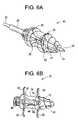
- FIG. 6Aillustrates an interspinous apparatus having stabilizers in a retracted state according to another exemplary embodiment of the present invention
- FIG. 6Billustrates an interspinous apparatus having stabilizers in a deployed state according to the exemplary embodiment of the present invention shown in FIG. 6A ;
- FIG. 7illustrates a locking mechanism according to an exemplary embodiment of the present invention
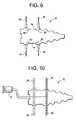
- FIG. 8illustrates an interspinous apparatus according to another exemplary embodiment of the present invention.
- FIG. 9illustrates an interspinous apparatus according to another exemplary embodiment of the present invention.
- FIG. 10illustrates an interspinous apparatus according to another exemplary embodiment of the present invention.
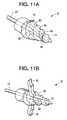
- FIGS. 11A and 11Billustrate an interspinous apparatus according to another exemplary embodiment of the present invention
- FIGS. 12A and 12Billustrate an interspinous apparatus according to another exemplary embodiment of the present invention.
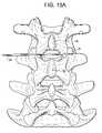
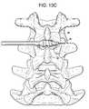
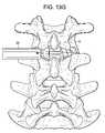
- FIGS. 13A-13Iillustrate a method of performing interspinous distraction according to an exemplary embodiment of the present invention.
- the deviceis composed of a device which has a pointed conical shape with embedded screw-shaped (i.e., helical) grooves that permit the passage of the device between the spinous processes of the human spine.
- the deviceis designed to be positioned between two spinous processes. It is placed through the interspinous ligament and below the supra-spinous ligament.
- the grooved conical surfacepermits the device to be screwed into place in a percutaneous or traditional open surgery.
- the deviceis secured between the spinous processes due to a deeper central engagement groove as well as by mechanisms to be described whereby the end(s) of the device are further stabilized. Due to its position within the interspinous ligament and below the supra-spinous ligament, further stability is obtained.
- the devicegradually spreads the spinous processes apart.
- the volume of the spinal canal and vertebral foramenare increased thereby decompressing the spine in cases of spinal stenosis.
- a unique feature of this procedureis that there is no required instrumentation to place the final device into its final position except for a device holding tool (i.e., an insertion driver). Provisional dilation of the spinous processes can be performed if so desired with solid dilators also of conical screw or a smooth semi-conical shape. The depth and pitch and other parameters of a screw configuration can be modified to provide faster insertion, more stable insertion, and positioning of the implant. The central groove may be deeper and broader to accept the spinous process anatomic region in a stable and consistent manner.
- the devicecan be either solid or cannulated.
- FIG. 1illustrates a high level drawing of an interspinous apparatus 10 according to an exemplary embodiment of the present invention.
- the interspinous apparatus 10includes a distractor 12 , an insertion driver 20 , and a guide wire 24 having a pointed tip 25 .
- the distractor 12has a conical shape which is adapted to enable passage of the distractor 12 between two spinous processes 26 of vertebrae such that a gradual distraction between the two spinous processes 26 occurs.
- Each of the distractor 12 and the insertion driver 20have a guide channel which extends through an entire central portion therein configured to accept the guide wire 24 therein.
- the pointed tip 25 of the guide wire 24permits an easier insertion of the guide wire 24 between the two spinous processes 26 .
- the guide wire 24is inserted between the two spinous processes 26 in order to guide the insertion of the distractor 12 , detachably coupled to the insertion driver 20 , between the two spinous processes 26 .
- the distractor 12has a conical shape which is adapted to enable passage of the distractor 12 between two spinous processes 26 that a gradual distraction between the two spinous processes 26 occurs. Due to the conical shape of the distractor 12 , the distractor 12 has an axis of distraction, to be described later, having a constant increasing angle that provides for constant distraction.
- the distractor 12can be composed of any solid or semi solid material including but not limited to poly-ether-ether-ketone (PEEK), titanium, stainless steel, or bone.
- the distractor 12may be composed of but not limited to hydroxyapatite, bone substitutes, a combination of hydroxyapatite and bone cement, CORTOSS, or the like. If the distractor 12 is composed of any material besides bone, motion is preserved due to the rolling effect of the cone in extension and flexion. If the distractor 12 is composed of bone, the device can be used to induce fusion. Thus, the device could also be used to fuse spines depending on what material it is made of.
- the central engagement groove 14can be partially flattened thereby decreasing the rolling effect of the device providing more stability.
- the distractor 12may be used to treat patients who require fusion with or without decompression of the spinal canal and foramen.
- materialssuch as PEEK, steel, titanium, or other alloys could be utilized.
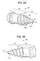
- FIGS. 2A and 2Billustrate a solid dilator 100 that is used before the distractor 12 according to an exemplary embodiment of the present invention.
- the dilator 100includes an insertion portion 113 and a central engagement groove 114 having a proximal end 115 and a distal end 116 .
- the insertion portion 113has a conical shape which tapers from the proximal end 115 of the central engagement groove 114 to a tip 117 and is adapted to enable passage of the dilator 100 between the two spinous processes 26 such that a gradual distraction between the two spinous processes 26 occurs.
- the insertion portion 113has embedded screw-shaped (i.e., helical) grooves 118 which permits the device to be screwed into place in a percutaneous or traditional open surgery.
- the grooves 118include sharp edges 118 A that are configured to incise through a patient's interspinous ligament (not shown).
- the edges 118 Acan serially dilates/spread the interspinous ligament apart. Moreover, the concave grooves 118 dilator keep the interspinous ligament distracted while the next edge 118 A incises the ligament.
- the insertion portion 113an axis of distraction 111 having a constant increasing angle that provides for constant distraction.
- the tip 117 of the insertion portion 113is ungrooved to allow for ease of initial insertions, but may be grooved.
- the tip 119is hollow, showing a portion of the guide channel 119 which extends through the entire central portion of the distractor 112 for accepting the guide wire 124 therein.
- the tip 119also includes a sharp edge 119 A this is configured to cut through the patient's interspinous ligament.
- the central engagement groove 114is adapted to secure the dilator 100 between the two spinous processes 26 such that the two spinous processes 26 rest in the central engagement groove 14 between the proximal end 115 and the distal end 116 .
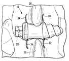
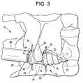
- FIG. 3illustrates an interspinous apparatus 10 according to another exemplary embodiment of the present invention.
- the distractoris inserted after the dilator 100 is removed and includes an insertion portion 13 and a central engagement groove 14 having a proximal end 15 and a distal end 16 .
- the insertion portion 13has a conical shape which tapers from the proximal end 15 of the central engagement groove 14 to a tip 17 and is adapted to enable passage of the distractor 12 between the two spinous processes 26 such that a gradual distraction between the two spinous processes 26 occurs.
- the insertion portion 13has embedded screw-shaped (i.e., helical) grooves 18 which permits the device to be screwed into place in a percutaneous or traditional open surgery.
- the insertion portion 13an axis of distraction 11 having a constant increasing angle that provides for constant distraction.
- the tip 17 of the insertion portion 13is ungrooved to allow for ease of initial insertions, but may be grooved.
- the tip 19is hollow, showing a portion of the guide channel 19 which extends through the entire central portion of the distractor 12 for accepting the guide wire 24 therein.
- the central engagement groove 14is adapted to secure the distractor 12 between the two spinous processes 26 such that the two spinous processes 26 rest in the central engagement groove 14 between the proximal end 15 and the distal end 16 .
- the interspinous apparatus 10includes the distractor 12 having a rear portion 28 detachably coupled to the insertion driver 20 , and the guide wire 24 .
- the insertion portion 13has a tip 17 which is grooved.
- the distractor 12includes a pair of proximal stabilization wings 30 retracted within a first cavity (not shown) of the distractor 12 and configured to be deployed through a pair of proximal slots 32 disposed on opposite sides of the proximal end 15 of the central engagement groove 14 .
- the stabilization wings 30are deployed after the spinous processes 26 are secured in the central engagement groove 14 to inhibit the distractor 12 from reversing out from between the two spinous processes 26 .
- the distractormay also include a pair of distal stabilization wings 34 retracted within a second cavity (not shown) of the distractor 12 and configured to be deployed through a pair of distal slots 36 disposed on opposite sides of the distal end 16 of the central engagement groove 14 .
- the stabilization wings 34are deployed after the spinous processes 26 are secured in the central engagement groove 14 to inhibit the distractor from being inserted further between the two spinous processes 26 .
- the proximal stabilization wings 30 and the distal stabilization wings 34stabilize the two spinous processes 26 within the central engagement groove 14 .
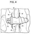
- FIG. 4illustrates an interspinous apparatus 10 having the insertion driver 20 decoupled from the rear portion 28 of the distractor 12 and the guide wire 24 removed from the distractor 12 .
- the distractor 12is shown implanted between the two spinous processes 26 and having the proximal stabilization wings 30 and the distal stabilization wings 34 deployed from within the distractor 12 .
- a circular ringcan be slipped over either end of the device and tightened thereby providing stability to the implant (not shown).
- FIG. 5illustrates an interspinous apparatus 10 according to another exemplary embodiment of the present invention.
- the distractor 12includes a stabilization base 36 in the alternative to the distal stabilization wings 34 .
- the stabilization base 36is coupled to the distal end 16 of the central engagement groove 14 and which extends outward from the distractor 12 .
- the stabilization base 36much like the distal stabilization wings 34 , is adapted to inhibit the distractor from being inserted further between the two spinous processes 26 .
- FIGS. 6A and 6Billustrate an interspinous apparatus having stabilizers 30 and 34 in a retracted state and in a deployed state, respectively, according to another exemplary embodiment of the present invention.
- the guide wire 24is disposed within the guide channel 19 , which extends through the entire central portion of the distractor 12 and the insertion driver 20 .
- Each guide channel 19 of the distractor 12 and the insertion driver 20is in alignment with each other.
- the distractor 12includes the pair of proximal stabilization wings 30 retracted within a first cavity 40 of the distractor 12 .
- the proximal stabilization wings 30are configured to be deployed through the pair of proximal slots 32 disposed on opposite sides of the proximal end 15 of the central engagement groove 14 .
- the distractor 12includes the pair of distal stabilization wings 34 retracted within a second cavity 42 of the distractor.
- the distal stabilization wings 34are configured to be deployed through the pair of distal slots 36 disposed on opposite sides of the distal end 16 of the central engagement groove 14 .
- the distractor 12includes a deployment bar 44 disposed therein and detachably coupled to the insertion driver 20 .
- the deployment bar 44is also coupled to each stabilization wing of the proximal stabilization wings 30 and the distal stabilization wings 34 .
- the deployment bar 44is disposed within the guide channel 19 of the distractor 12 and is configured to be slidably switched between an extended position (as shown in FIG. 6A ) and a retracted position (as shown in FIG. 6B ).
- the deployment bar 44when the deployment bar 44 is in the extended position, the deployment bar 44 maintains the proximal stabilization wings 30 and the distal stabilization wings 34 in a retracted state. On the other hand, when deployment bar 44 is in the retracted position, the deployment bar 44 releases the proximal stabilization wings 30 and the distal stabilization wings 34 to a deployed state.
- the deployment bar 44is slidably switched between the extended position and the retracted position by moving the portion of the insertion driver 20 that is detachably coupled to the deployment bar 44 in and out of the distractor 12 .
- the stabilization wings 30 and 34may be locked into their deployed position by a lock configured to engage with the deployment bar 44 .
- the portion of the insertion driver 20 that is detachably coupled to the deployment bar 44may be rotated, and in turn rotating the deployment bar 44 within the distractor 12 to a locked position. Once in a locked state, the insertion driver 20 can be decoupled from the deployment bar 44 and removed from the guide wire 24 .
- FIG. 7illustrates a locking mechanism according to an exemplary embodiment of the present invention.
- a rear portion 46(as shown in FIGS. 6A and 6B ) of the deployment bar 44 has interlocking members 47 which can be rotated clockwise to engage locking slots 48 to lock the deployment bar 44 into place, and thereby, locking the stabilization wings 30 and 34 in the deployed state.
- FIG. 8illustrates an interspinous apparatus according to another exemplary embodiment of the present invention.
- FIG. 8illustrates an alternative mechanism for deploying the proximal stabilization wings 30 and the distal stabilization wings 34 .
- the distractor 12includes an insertion screw driver 50 disposed within the guide channel of the distractor, coupled to the insertion driver 20 and configured to engage a first pair of gears 52 and a second pair of gears 54 .
- Each gear 52 and 54is mechanically coupled to a respective stabilization wing 30 and 34 .
- the insertion screw driver 50is turned within the distractor 12 and engages with the first pair of gears 52 to deploy the pair of proximal stabilization wings 30 from the proximal slots 32 and engages with the second pair of gears 54 to deploy the pair of distal stabilization wings 34 from the distal slots 36 .
- FIG. 9illustrates an interspinous apparatus according to another exemplary embodiment of the present invention.
- FIG. 9illustrates an alternative mechanism for deploying the proximal stabilization wings 30 and the distal stabilization wings 34 .
- Each stabilization wing of the pair of proximal stabilization wings 30 and the pair of distal stabilization wings 34are coupled to the central engagement groove 14 by a pressure mechanism 60 such that the stabilization wings 30 and 34 are deployed when the central engagement groove 14 is pressurized by compression from the two spinous processes 26 upon insertion therebetween.
- the pressure on the central engagement groove 14deploys the stabilization wings 30 and 34 from within the distractor 12 .
- FIG. 10illustrates an interspinous apparatus according to another exemplary embodiment of the present invention.
- FIG. 10illustrates an alternative mechanism for deploying the proximal stabilization wings 30 and the distal stabilization wings 34 .
- the proximal stabilization wings 30 and distal stabilization wingsare balloon O-rings such that the stabilization wings 30 and 34 are deflated in a retracted state and inflated in a deployed state.
- a pump 70 coupled to each of the proximal stabilization wings 30 and distal stabilization wings 34is used to inflate the proximal stabilization wings 30 and the distal stabilization wings to a deployed state 34 .
- the O-ringscan be inflated with either a gas or a liquid to stabilize the implant.
- FIGS. 11A and 11Billustrate an interspinous apparatus according to another exemplary embodiment of the present invention.
- FIGS. 11A and 11Billustrate an alternative mechanism for deploying the proximal stabilization wings 30 .
- FIGS. 11A and 11Billustrate an interspinous apparatus having stabilizers 30 in a retracted state and in a deployed state, respectively, according to another exemplary embodiment of the present invention.
- the insertion portion 13includes a pair of axial rectangular grooves 80 , each disposed oppositely from each other. Within the pair of axial rectangular grooves 80 is disposed the pair of proximal stabilization wings 30 or side wings. Each proximal stabilization wing 30 is disposed within one of the pair of axial rectangular grooves 80 . Furthermore, the proximal stabilization wings 30 are configured to be congruent with a shape of the axial rectangular grooves 80 and with a surface of the insertion portion 13 in an undeployed state as shown in FIG. 11A .
- a surfaces of the proximal stabilization wings 30also have grooves to be congruent the grooved surface of the insertion portion 13 . This enables the distractor 12 to be screwed into place between the two spinous processes 26 when the proximal stabilization wings 30 are undeployed.
- the proximal stabilization wings 30are also configured to be deployed outward from the axial rectangular grooves 80 as shown in FIG. 11B .
- a deployment means 82deploys the pair of proximal stabilization wings 30 from the axial rectangular grooves 80 by pulling the stabilization wings 30 towards the proximal end 15 of the central engagement groove 14 such that such that the stabilization wings 30 open up from the axial rectangular grooves 80 to a vertical position adjacent to the proximal end 15 of the central engagement groove 14 .
- the stabilization wings 30are coupled to the deployment means 82 by a pair of hinges 84 , enabling the stabilization wings 30 to open to a deployed state.
- the distractor 12may also include the stabilization base 36 similar to that shown in FIG. 5 .
- FIGS. 12A and 12Billustrate an interspinous apparatus according to another exemplary embodiment of the present invention.
- FIGS. 12A and 12Billustrate an alternative mechanism for deploying a stabilizer.
- the distractor 12and more particularly, the insertion portion 13 may be composed of differing materials to permit for a collapsing umbrella stabilizing tip to be deployed.
- the insertion portion 13is made of flexible material having a first diameter D 1 at the proximal end 15 of the central engagement groove 14 .
- the insertion portion 13is configured to collapse towards the proximal end of the central engagement groove such that the insertion portion 13 is compressed into a shape having a second diameter D 2 at the proximal end 15 of the central engagement groove 14 larger than the first diameter D 1 after the distractor 12 is implanted to inhibit the distractor 12 from reversing out from between the two spinous processes 26 .
- the distractor 12includes a wire 90 fed through the guide channel 19 and connected to the tip 17 of the insertion portion 13 .
- the tip 17 of the insertion portion 13is adapted to be pulled towards the central engagement groove 14 upon pulling of the wire 90 to collapse the insertion portion 13 .
- the length of portion Bcollapses, while the length of portion A remains constant and rigid.
- the distractor 12may also include the stabilization base 36 similar to that shown in FIG. 5 .
- stabilization base 36 as described in FIG. 5could be implemented in any of the above exemplary embodiments.
- FIGS. 13A-13Hillustrate a method of performing interspinous distraction according to an exemplary embodiment of the present invention.
- the methodincludes inserting a guide wire 24 having a pointed tip 25 between the two spinous processes 26 ( FIG. 13A ).
- the guide wire 24is configured to guide the insertion of the distractor 12 and the inserting of the insertion driver 20 between the two spinous processes 26 while the insertion driver 20 is coupled to the distractor 12 .
- the distractor 12 and the insertion driver 20each have a guide channel 19 disposed therein configured to accept the guide wire 24 therein.
- Provisional dilation of the spinous processes 26is performed with cannulated conical screw or smooth semi conical shape dilators 100 and 100 , as shown in FIGS. 13B and 13C .
- the first dilator 100is inserted via the guide wire 24 and cuts through the interspinous ligament (not shown) using the sharp edges 117 A, 118 A.
- the dilator 100distracts the spinous processes 26 if the dilator 100 comes into contact with the spinous processes 26 . Then, the first dilator 100 is removed.
- a second dilator 101is inserted via the guide wire 24 .
- the second dilator 101is larger than the first dilator 100 and also cuts through the interspinous ligament. If necessary, several dilators 100 , 101 , etc. can be used until one of the dilators contacts the spinous processes 26 .
- the dilatorscan have slightly increasing outer diameters. For example, a 6 mm, an 8 mm, a 10 mm, a 12 mm, and a 14 mm dilator can be used.
- a distractor of an appropriate sizecan be selected.
- the methodfurther includes inserting the distractor 12 having a conical insertion portion 13 and a central engagement groove 14 between the two spinous processes 26 ( FIG. 13D ).
- the conical insertion portion 13is adapted such that a gradual distraction between the two spinous processes occurs 26 .
- the insertion drive 20acts as a device holding tool for inserting the distractor 12 between the spinous processes 26 .
- FIG. 13Dalso illustrates inserting the insertion driver 20 while coupled to the distractor 12 , the insertion driver 20 being detachably coupled to a rear portion 28 of the distractor 12 .
- the methodfurther includes implanting the distractor 12 between the two spinous processes 26 such that the two spinous processes 26 rest in the central engagement groove 14 between a proximal end 15 and a distal end 16 of the central engagement groove 14 ( FIG. 13E ).
- the methodfurther includes deploying a stabilizer (e.g., stabilization wings 30 and 34 ) which is adapted to be deployed from within the distractor 12 to secure the two spinous processes 26 within the central engagement groove 14 ( FIG. 13F ).
- the stabilizermay also be locked into the deployed state ( FIG. 13F ).
- the methodfurther includes decoupling the insertion driver 20 from the distractor 12 ( FIG. 13G and 13H ) and removing the insertion driver 20 and the guide wire 24 ( FIG. 13I ).
Landscapes
- Health & Medical Sciences (AREA)
- Orthopedic Medicine & Surgery (AREA)
- Life Sciences & Earth Sciences (AREA)
- Neurology (AREA)
- Surgery (AREA)
- Heart & Thoracic Surgery (AREA)
- Engineering & Computer Science (AREA)
- Biomedical Technology (AREA)
- Nuclear Medicine, Radiotherapy & Molecular Imaging (AREA)
- Medical Informatics (AREA)
- Molecular Biology (AREA)
- Animal Behavior & Ethology (AREA)
- General Health & Medical Sciences (AREA)
- Public Health (AREA)
- Veterinary Medicine (AREA)
- Prostheses (AREA)
- Surgical Instruments (AREA)
Abstract
Description
Claims (29)
Priority Applications (9)
| Application Number | Priority Date | Filing Date | Title |
|---|---|---|---|
| US12/343,082US8172878B2 (en) | 2008-08-27 | 2008-12-23 | Conical interspinous apparatus and a method of performing interspinous distraction |
| CN200980000373.6ACN101795632B (en) | 2008-08-27 | 2009-08-27 | Conical interspinous apparatus and a method of performing interspinous distraction |
| EP09791972.4AEP2328490B1 (en) | 2008-08-27 | 2009-08-27 | Conical interspinous apparatus |
| PCT/US2009/055124WO2010027886A1 (en) | 2008-08-27 | 2009-08-27 | Conical interspinous apparatus and a method of performing interspinous distraction |
| ES09791972.4TES2623851T3 (en) | 2008-08-27 | 2009-08-27 | Conical interspinous apparatus |
| US12/616,245US8192466B2 (en) | 2008-08-27 | 2009-11-11 | Conical interspinous apparatus and a method of performing interspinous distraction |
| PCT/US2009/064040WO2010074829A1 (en) | 2008-12-23 | 2009-11-11 | Conical interspinous apparatus and a method of performing interspinous distraction |
| US13/461,972US8518083B2 (en) | 2008-08-27 | 2012-05-02 | Conical interspinous apparatus and a method of performing interspinous distraction |
| US13/478,564US8747440B2 (en) | 2008-08-27 | 2012-05-23 | Conical interspinous apparatus and a method of performing interspinous distraction |
Applications Claiming Priority (2)
| Application Number | Priority Date | Filing Date | Title |
|---|---|---|---|
| US9214208P | 2008-08-27 | 2008-08-27 | |
| US12/343,082US8172878B2 (en) | 2008-08-27 | 2008-12-23 | Conical interspinous apparatus and a method of performing interspinous distraction |
Related Child Applications (3)
| Application Number | Title | Priority Date | Filing Date |
|---|---|---|---|
| US12/616,245Continuation-In-PartUS8192466B2 (en) | 2008-08-27 | 2009-11-11 | Conical interspinous apparatus and a method of performing interspinous distraction |
| US12/616,425Continuation-In-PartUS7913967B1 (en) | 2009-11-11 | 2009-11-11 | Adjustable picture-hanger assembly |
| US13/461,972DivisionUS8518083B2 (en) | 2008-08-27 | 2012-05-02 | Conical interspinous apparatus and a method of performing interspinous distraction |
Publications (2)
| Publication Number | Publication Date |
|---|---|
| US20100057130A1 US20100057130A1 (en) | 2010-03-04 |
| US8172878B2true US8172878B2 (en) | 2012-05-08 |
Family
ID=41571840
Family Applications (2)
| Application Number | Title | Priority Date | Filing Date |
|---|---|---|---|
| US12/343,082Expired - Fee RelatedUS8172878B2 (en) | 2008-08-27 | 2008-12-23 | Conical interspinous apparatus and a method of performing interspinous distraction |
| US13/461,972Expired - Fee RelatedUS8518083B2 (en) | 2008-08-27 | 2012-05-02 | Conical interspinous apparatus and a method of performing interspinous distraction |
Family Applications After (1)
| Application Number | Title | Priority Date | Filing Date |
|---|---|---|---|
| US13/461,972Expired - Fee RelatedUS8518083B2 (en) | 2008-08-27 | 2012-05-02 | Conical interspinous apparatus and a method of performing interspinous distraction |
Country Status (4)
| Country | Link |
|---|---|
| US (2) | US8172878B2 (en) |
| EP (1) | EP2328490B1 (en) |
| CN (1) | CN101795632B (en) |
| WO (2) | WO2010027886A1 (en) |
Cited By (5)
| Publication number | Priority date | Publication date | Assignee | Title |
|---|---|---|---|---|
| US20110172710A1 (en)* | 2009-11-06 | 2011-07-14 | Synthes Usa, Llc | Minimally invasive interspinous process spacer implants and methods |
| US20150305785A1 (en)* | 2007-11-02 | 2015-10-29 | Lanx, Inc. | Interspinous implants with deployable wing |
| US9693876B1 (en) | 2012-03-30 | 2017-07-04 | Ali H. MESIWALA | Spinal fusion implant and related methods |
| US20220249243A1 (en)* | 2019-07-08 | 2022-08-11 | Innospina Sarl | Interspinous implant and associated implantation ancillary |
| US12263095B2 (en) | 2020-08-20 | 2025-04-01 | Spinal Simplicity, Llc | Interspinous process implant |
Families Citing this family (50)
| Publication number | Priority date | Publication date | Assignee | Title |
|---|---|---|---|---|
| US20180228621A1 (en) | 2004-08-09 | 2018-08-16 | Mark A. Reiley | Apparatus, systems, and methods for the fixation or fusion of bone |
| US8414648B2 (en) | 2004-08-09 | 2013-04-09 | Si-Bone Inc. | Apparatus, systems, and methods for achieving trans-iliac lumbar fusion |
| US9662158B2 (en) | 2004-08-09 | 2017-05-30 | Si-Bone Inc. | Systems and methods for the fixation or fusion of bone at or near a sacroiliac joint |
| US9949843B2 (en) | 2004-08-09 | 2018-04-24 | Si-Bone Inc. | Apparatus, systems, and methods for the fixation or fusion of bone |
| US8388667B2 (en) | 2004-08-09 | 2013-03-05 | Si-Bone, Inc. | Systems and methods for the fixation or fusion of bone using compressive implants |
| US8425570B2 (en) | 2004-08-09 | 2013-04-23 | Si-Bone Inc. | Apparatus, systems, and methods for achieving anterior lumbar interbody fusion |
| US8500778B2 (en)* | 2006-02-01 | 2013-08-06 | DePuy Synthes Products, LLC | Interspinous process spacer |
| CN101854887B (en)* | 2007-05-01 | 2013-09-25 | 斯百诺辛普利斯提有限责任公司 | Interspinous implants and methods for implanting same |
| EP2142146A4 (en)* | 2007-05-01 | 2010-12-01 | Spinal Simplicity Llc | Interspinous implants and methods for implanting same |
| US8142479B2 (en)* | 2007-05-01 | 2012-03-27 | Spinal Simplicity Llc | Interspinous process implants having deployable engagement arms |
| ITPI20080010A1 (en)* | 2008-02-07 | 2009-08-08 | Giuseppe Calvosa | INTERSTEIN VERTEBRAL DISTRACTOR FOR PERCUTANEOUS INSERTION |
| US9861399B2 (en)* | 2009-03-13 | 2018-01-09 | Spinal Simplicity, Llc | Interspinous process implant having a body with a removable end portion |
| US9757164B2 (en)* | 2013-01-07 | 2017-09-12 | Spinal Simplicity Llc | Interspinous process implant having deployable anchor blades |
| US8945184B2 (en)* | 2009-03-13 | 2015-02-03 | Spinal Simplicity Llc. | Interspinous process implant and fusion cage spacer |
| US8343035B2 (en)* | 2009-04-20 | 2013-01-01 | Spine View, Inc. | Dilator with direct visualization |
| US8827902B2 (en) | 2010-08-16 | 2014-09-09 | Donald David DIETZE, Jr. | Surgical instrument system and method for providing retraction and vertebral distraction |
| ES2390766B1 (en)* | 2010-09-30 | 2014-01-17 | Biotechnology Institute, I Mas D, S.L. | OSEA CRESTA EXPANSION METHOD AND AN EXPANSOR IMPLANT TO BE USED IN THIS METHOD |
| US8603143B2 (en) | 2010-12-05 | 2013-12-10 | James C. Robinson | Spinous process fixation apparatus |
| US8603142B2 (en) | 2010-12-05 | 2013-12-10 | James C. Robinson | Spinous process fixation apparatus and method |
| CN101991459B (en)* | 2010-12-10 | 2012-12-26 | 上海凯利泰医疗科技股份有限公司 | Flick spinous process propping device |
| US10363140B2 (en) | 2012-03-09 | 2019-07-30 | Si-Bone Inc. | Systems, device, and methods for joint fusion |
| US9044321B2 (en) | 2012-03-09 | 2015-06-02 | Si-Bone Inc. | Integrated implant |
| EP3818947B1 (en) | 2012-05-04 | 2023-08-30 | SI-Bone, Inc. | Fenestrated implant |
| WO2014145902A1 (en) | 2013-03-15 | 2014-09-18 | Si-Bone Inc. | Implants for spinal fixation or fusion |
| CN104116579B (en)* | 2013-04-28 | 2016-08-03 | 苏州海欧斯医疗器械有限公司 | Implantation unit is strutted between a kind of Via Posterior Spinal Approach ridge |
| KR20160016919A (en)* | 2013-05-29 | 2016-02-15 | 스파이널 심플리서티 엘엘씨 | Instrument for inserting an interspinous process implant |
| US9839448B2 (en) | 2013-10-15 | 2017-12-12 | Si-Bone Inc. | Implant placement |
| US11147688B2 (en) | 2013-10-15 | 2021-10-19 | Si-Bone Inc. | Implant placement |
| US10166033B2 (en) | 2014-09-18 | 2019-01-01 | Si-Bone Inc. | Implants for bone fixation or fusion |
| JP6542362B2 (en) | 2014-09-18 | 2019-07-10 | エスアイ−ボーン・インコーポレイテッドSi−Bone, Inc. | Matrix implant |
| US10022246B2 (en) | 2014-12-16 | 2018-07-17 | Donald Mackenzie | Interlaminar fixation device |
| US10376206B2 (en) | 2015-04-01 | 2019-08-13 | Si-Bone Inc. | Neuromonitoring systems and methods for bone fixation or fusion procedures |
| EP3297554B1 (en)* | 2015-05-22 | 2024-04-24 | Spinal Simplicity LLC | Interspinous process implant having a body with a removable end portion |
| US9724502B2 (en)* | 2015-07-10 | 2017-08-08 | Coloplast A/S | Dilator and method for penile prosthetic implantation |
| US11510710B2 (en) | 2016-04-14 | 2022-11-29 | Spinal Simplicity, Llc | Locking system for interspinous implant insertion instrument |
| US11116519B2 (en) | 2017-09-26 | 2021-09-14 | Si-Bone Inc. | Systems and methods for decorticating the sacroiliac joint |
| US10864029B2 (en)* | 2018-01-26 | 2020-12-15 | West End Bay Partners, Llc | Sacroiliac joint stabilization and fixation devices and related methods |
| ES3011907T3 (en) | 2018-03-28 | 2025-04-08 | Si Bone Inc | Threaded implants for use across bone segments |
| EP4613244A2 (en) | 2019-02-14 | 2025-09-10 | SI-Bone Inc. | Implants for spinal fixation and or fusion |
| US11369419B2 (en) | 2019-02-14 | 2022-06-28 | Si-Bone Inc. | Implants for spinal fixation and or fusion |
| JP7646654B2 (en) | 2019-11-21 | 2025-03-17 | エスアイ-ボーン・インコーポレイテッド | Rod coupling assembly for bone stabilization construct - Patent application |
| AU2020392121B2 (en) | 2019-11-27 | 2025-05-22 | Si-Bone, Inc. | Bone stabilizing implants and methods of placement across SI joints |
| EP4072452A4 (en) | 2019-12-09 | 2023-12-20 | SI-Bone, Inc. | Sacro-iliac joint stabilizing implants and methods of implantation |
| US11311388B2 (en) | 2020-08-20 | 2022-04-26 | Spinal Simplicity, Llc | Interspinous process implant |
| EP4259015A4 (en) | 2020-12-09 | 2024-09-11 | SI-Bone, Inc. | SACROILIAC JOINT STABILIZATION IMPLANTS AND METHODS OF IMPLANTATION |
| CN115670628A (en)* | 2021-07-23 | 2023-02-03 | 艾派(广州)医疗器械有限公司 | Fixator for opening and keeping interspinous space |
| US11672572B1 (en) | 2022-04-08 | 2023-06-13 | Spinal Simplicity, Llc | Disposable interspinous implant insertion instrument |
| US11849975B1 (en)* | 2022-11-09 | 2023-12-26 | Spinal Simplicity, Llc | Methods for single incision anterior and posterior spinal fusion procedure |
| US12133664B2 (en) | 2022-12-13 | 2024-11-05 | Spinal Simplicity, Llc | Medical implant |
| WO2025038769A1 (en) | 2023-08-15 | 2025-02-20 | Si-Bone Inc. | Pelvic stabilization implants, methods of use and manufacture |
Citations (28)
| Publication number | Priority date | Publication date | Assignee | Title |
|---|---|---|---|---|
| US5609634A (en) | 1992-07-07 | 1997-03-11 | Voydeville; Gilles | Intervertebral prosthesis making possible rotatory stabilization and flexion/extension stabilization |
| US5645599A (en) | 1994-07-26 | 1997-07-08 | Fixano | Interspinal vertebral implant |
| US5836948A (en) | 1997-01-02 | 1998-11-17 | Saint Francis Medical Technologies, Llc | Spine distraction implant and method |
| US5860977A (en) | 1997-01-02 | 1999-01-19 | Saint Francis Medical Technologies, Llc | Spine distraction implant and method |
| US6048342A (en) | 1997-01-02 | 2000-04-11 | St. Francis Medical Technologies, Inc. | Spine distraction implant |
| US6068630A (en) | 1997-01-02 | 2000-05-30 | St. Francis Medical Technologies, Inc. | Spine distraction implant |
| US6152926A (en) | 1997-01-02 | 2000-11-28 | St. Francis Medical Technologies, Inc. | Spine distraction implant and method |
| US20010012938A1 (en) | 1997-01-02 | 2001-08-09 | Zucherman James F. | Spine distraction implant |
| US20010016743A1 (en) | 1997-01-02 | 2001-08-23 | St. Francis Medical Technologies, Inc. | Spine distraction implant and method |
| US6440169B1 (en) | 1998-02-10 | 2002-08-27 | Dimso | Interspinous stabilizer to be fixed to spinous processes of two vertebrae |
| US20030114854A1 (en) | 1994-09-15 | 2003-06-19 | Howmedica Osteonics Corp. | Conically shaped anterior fusion cage and method of implantation |
| US6733534B2 (en) | 2002-01-29 | 2004-05-11 | Sdgi Holdings, Inc. | System and method for spine spacing |
| US20050165398A1 (en) | 2004-01-26 | 2005-07-28 | Reiley Mark A. | Percutaneous spine distraction implant systems and methods |
| WO2006064356A1 (en) | 2004-12-16 | 2006-06-22 | Doellinger Horst | Implant for the treatment of lumbar spinal canal stenosis |
| US20060265066A1 (en) | 2005-03-21 | 2006-11-23 | St. Francis Medical Technologies, Inc. | Interspinous process implant having a thread-shaped wing and method of implantation |
| US20060264938A1 (en) | 2005-03-21 | 2006-11-23 | St. Francis Medical Technologies, Inc. | Interspinous process implant having deployable wing and method of implantation |
| US20060271049A1 (en) | 2005-04-18 | 2006-11-30 | St. Francis Medical Technologies, Inc. | Interspinous process implant having deployable wings and method of implantation |
| US20070055237A1 (en) | 2005-02-17 | 2007-03-08 | Edidin Avram A | Percutaneous spinal implants and methods |
| US20070149972A1 (en) | 2003-05-16 | 2007-06-28 | Yoshinobu Iwasaki | Interspinous spacer |
| GB2436293A (en) | 2006-03-24 | 2007-09-26 | Galley Geoffrey H | Spinous processes insertion device |
| US20080027438A1 (en) | 2006-07-27 | 2008-01-31 | Abdou M S | Devices and methods for the minimally invasive treatment of spinal stenosis |
| US20080058935A1 (en) | 2005-02-17 | 2008-03-06 | Malandain Hugues F | Percutaneous spinal implants and methods |
| US20080071280A1 (en) | 2004-04-28 | 2008-03-20 | St. Francis Medical Technologies, Inc. | System and Method for Insertion of an Interspinous Process Implant that is Rotatable in Order to Retain the Implant Relative to the Spinous Processes |
| EP1920719A1 (en) | 2005-08-11 | 2008-05-14 | National University Corp. Kobe University | Minimally-invasive implant for opening and enlargement of processus spinosus interspace and method of percutaneously enlarging processus spinosus interspace therewith |
| US20080161822A1 (en) | 2006-12-28 | 2008-07-03 | Mi4Spine, Llc | Minimally invasive interspinous process spacer insertion device |
| US20080177312A1 (en) | 2006-12-28 | 2008-07-24 | Mi4Spine, Llc | Interspinous Process Spacer Device |
| US20080243250A1 (en)* | 2007-03-26 | 2008-10-02 | Seifert Jody L | Lateral Spinous Process Spacer |
| US20090326581A1 (en)* | 2006-03-24 | 2009-12-31 | Geoffrey Harrison Galley | Expandable spacing means for insertion between spinous processes of adjacent vertebrae |
Family Cites Families (1)
| Publication number | Priority date | Publication date | Assignee | Title |
|---|---|---|---|---|
| CN201088619Y (en)* | 2007-08-31 | 2008-07-23 | 周跃 | Combinated multifunctional lumbar fusion device |
- 2008
- 2008-12-23USUS12/343,082patent/US8172878B2/ennot_activeExpired - Fee Related
- 2009
- 2009-08-27EPEP09791972.4Apatent/EP2328490B1/ennot_activeNot-in-force
- 2009-08-27WOPCT/US2009/055124patent/WO2010027886A1/enactiveApplication Filing
- 2009-08-27CNCN200980000373.6Apatent/CN101795632B/ennot_activeExpired - Fee Related
- 2009-11-11WOPCT/US2009/064040patent/WO2010074829A1/enactiveApplication Filing
- 2012
- 2012-05-02USUS13/461,972patent/US8518083B2/ennot_activeExpired - Fee Related
Patent Citations (43)
| Publication number | Priority date | Publication date | Assignee | Title |
|---|---|---|---|---|
| US5609634A (en) | 1992-07-07 | 1997-03-11 | Voydeville; Gilles | Intervertebral prosthesis making possible rotatory stabilization and flexion/extension stabilization |
| US5645599A (en) | 1994-07-26 | 1997-07-08 | Fixano | Interspinal vertebral implant |
| US20030114854A1 (en) | 1994-09-15 | 2003-06-19 | Howmedica Osteonics Corp. | Conically shaped anterior fusion cage and method of implantation |
| US6190387B1 (en) | 1997-01-02 | 2001-02-20 | St. Francis Medical Technologies, Inc. | Spine distraction implant |
| US6238397B1 (en) | 1997-01-02 | 2001-05-29 | St. Francis Technologies, Inc. | Spine distraction implant and method |
| US6048342A (en) | 1997-01-02 | 2000-04-11 | St. Francis Medical Technologies, Inc. | Spine distraction implant |
| US6068630A (en) | 1997-01-02 | 2000-05-30 | St. Francis Medical Technologies, Inc. | Spine distraction implant |
| US6074390A (en) | 1997-01-02 | 2000-06-13 | St. Francis Medical Technologies, Inc. | Spine distraction implant and method |
| US6090112A (en) | 1997-01-02 | 2000-07-18 | St. Francis Medical Technologies, Inc. | Spine distraction implant and method |
| US6152926A (en) | 1997-01-02 | 2000-11-28 | St. Francis Medical Technologies, Inc. | Spine distraction implant and method |
| US6156038A (en) | 1997-01-02 | 2000-12-05 | St. Francis Medical Technologies, Inc. | Spine distraction implant and method |
| US6183471B1 (en) | 1997-01-02 | 2001-02-06 | St. Francis Medical Technologies, Inc. | Spine distraction implant and method |
| US5860977A (en) | 1997-01-02 | 1999-01-19 | Saint Francis Medical Technologies, Llc | Spine distraction implant and method |
| US6235030B1 (en) | 1997-01-02 | 2001-05-22 | St. Francis Medical Technologies, Inc. | Spine distraction implant |
| US5876404A (en) | 1997-01-02 | 1999-03-02 | St. Francis Medical Technologies, Llc | Spine distraction implant and method |
| US20010012938A1 (en) | 1997-01-02 | 2001-08-09 | Zucherman James F. | Spine distraction implant |
| US20010016776A1 (en) | 1997-01-02 | 2001-08-23 | St. Francis Medical Technologies | Spine distraction implant and method |
| US20010016743A1 (en) | 1997-01-02 | 2001-08-23 | St. Francis Medical Technologies, Inc. | Spine distraction implant and method |
| US6332883B1 (en) | 1997-01-02 | 2001-12-25 | St. Francis Medical Technologies, Inc. | Spine distraction implant |
| US6419677B2 (en) | 1997-01-02 | 2002-07-16 | St. Francis Medical Technologies, Inc. | Spine distraction implant and method |
| US5836948A (en) | 1997-01-02 | 1998-11-17 | Saint Francis Medical Technologies, Llc | Spine distraction implant and method |
| US6451020B1 (en) | 1997-01-02 | 2002-09-17 | St. Francis Medical Technologies, Inc. | Spine distraction implant and method |
| US6478796B2 (en) | 1997-01-02 | 2002-11-12 | St. Francis Medical Technologies, Inc. | Spin distraction implant and method |
| US6514256B2 (en) | 1997-01-02 | 2003-02-04 | St. Francis Medical Technologies, Inc. | Spine distraction implant and method |
| US6440169B1 (en) | 1998-02-10 | 2002-08-27 | Dimso | Interspinous stabilizer to be fixed to spinous processes of two vertebrae |
| US6733534B2 (en) | 2002-01-29 | 2004-05-11 | Sdgi Holdings, Inc. | System and method for spine spacing |
| US20070149972A1 (en) | 2003-05-16 | 2007-06-28 | Yoshinobu Iwasaki | Interspinous spacer |
| US20050165398A1 (en) | 2004-01-26 | 2005-07-28 | Reiley Mark A. | Percutaneous spine distraction implant systems and methods |
| US20080071280A1 (en) | 2004-04-28 | 2008-03-20 | St. Francis Medical Technologies, Inc. | System and Method for Insertion of an Interspinous Process Implant that is Rotatable in Order to Retain the Implant Relative to the Spinous Processes |
| WO2006064356A1 (en) | 2004-12-16 | 2006-06-22 | Doellinger Horst | Implant for the treatment of lumbar spinal canal stenosis |
| US20080058935A1 (en) | 2005-02-17 | 2008-03-06 | Malandain Hugues F | Percutaneous spinal implants and methods |
| US20070055237A1 (en) | 2005-02-17 | 2007-03-08 | Edidin Avram A | Percutaneous spinal implants and methods |
| US20060264938A1 (en) | 2005-03-21 | 2006-11-23 | St. Francis Medical Technologies, Inc. | Interspinous process implant having deployable wing and method of implantation |
| US20060265066A1 (en) | 2005-03-21 | 2006-11-23 | St. Francis Medical Technologies, Inc. | Interspinous process implant having a thread-shaped wing and method of implantation |
| US20080045958A1 (en) | 2005-04-18 | 2008-02-21 | Zucherman James F | Interspinous process implant having deployable wings and method of implantation |
| US20060271049A1 (en) | 2005-04-18 | 2006-11-30 | St. Francis Medical Technologies, Inc. | Interspinous process implant having deployable wings and method of implantation |
| EP1920719A1 (en) | 2005-08-11 | 2008-05-14 | National University Corp. Kobe University | Minimally-invasive implant for opening and enlargement of processus spinosus interspace and method of percutaneously enlarging processus spinosus interspace therewith |
| GB2436293A (en) | 2006-03-24 | 2007-09-26 | Galley Geoffrey H | Spinous processes insertion device |
| US20090326581A1 (en)* | 2006-03-24 | 2009-12-31 | Geoffrey Harrison Galley | Expandable spacing means for insertion between spinous processes of adjacent vertebrae |
| US20080027438A1 (en) | 2006-07-27 | 2008-01-31 | Abdou M S | Devices and methods for the minimally invasive treatment of spinal stenosis |
| US20080161822A1 (en) | 2006-12-28 | 2008-07-03 | Mi4Spine, Llc | Minimally invasive interspinous process spacer insertion device |
| US20080177312A1 (en) | 2006-12-28 | 2008-07-24 | Mi4Spine, Llc | Interspinous Process Spacer Device |
| US20080243250A1 (en)* | 2007-03-26 | 2008-10-02 | Seifert Jody L | Lateral Spinous Process Spacer |
Cited By (14)
| Publication number | Priority date | Publication date | Assignee | Title |
|---|---|---|---|---|
| US20150305785A1 (en)* | 2007-11-02 | 2015-10-29 | Lanx, Inc. | Interspinous implants with deployable wing |
| US9750544B2 (en)* | 2007-11-02 | 2017-09-05 | Zimmer Biomet Spine, Inc. | Interspinous implants with deployable wing |
| US9155571B2 (en) | 2009-11-06 | 2015-10-13 | DePuy Synthes Products, Inc. | Minimally invasive interspinous process spacer implants and methods |
| US20110172710A1 (en)* | 2009-11-06 | 2011-07-14 | Synthes Usa, Llc | Minimally invasive interspinous process spacer implants and methods |
| US8702757B2 (en)* | 2009-11-06 | 2014-04-22 | DePuy Synthes Products, LLC | Minimally invasive interspinous process spacer implants and methods |
| US20110190817A1 (en)* | 2009-11-06 | 2011-08-04 | Synthes Usa, Llc | Minimally invasive interspinous process spacer implants and methods |
| US9924978B2 (en) | 2009-11-06 | 2018-03-27 | DePuy Synthes Products, Inc. | Minimally invasive interspinous process spacer implants and methods |
| US10729476B2 (en) | 2009-11-06 | 2020-08-04 | DePuy Synthes Products, Inc. | Minimally invasive interspinous process spacer implants and methods |
| US9693876B1 (en) | 2012-03-30 | 2017-07-04 | Ali H. MESIWALA | Spinal fusion implant and related methods |
| US10238504B2 (en) | 2012-03-30 | 2019-03-26 | Ali H. MESIWALA | Spinal fusion implant and related methods |
| US10561447B2 (en) | 2012-12-31 | 2020-02-18 | Zimmer Biomet Spine, Inc. | Interspinous implants with deployable wing |
| US20220249243A1 (en)* | 2019-07-08 | 2022-08-11 | Innospina Sarl | Interspinous implant and associated implantation ancillary |
| US12318302B2 (en)* | 2019-07-08 | 2025-06-03 | Innospina Sarl | Interspinous implant and associated implantation ancillary |
| US12263095B2 (en) | 2020-08-20 | 2025-04-01 | Spinal Simplicity, Llc | Interspinous process implant |
Also Published As
| Publication number | Publication date |
|---|---|
| EP2328490A1 (en) | 2011-06-08 |
| US20120265251A1 (en) | 2012-10-18 |
| US8518083B2 (en) | 2013-08-27 |
| US20100057130A1 (en) | 2010-03-04 |
| WO2010027886A1 (en) | 2010-03-11 |
| CN101795632A (en) | 2010-08-04 |
| CN101795632B (en) | 2013-06-12 |
| WO2010074829A1 (en) | 2010-07-01 |
| EP2328490B1 (en) | 2017-02-01 |
Similar Documents
| Publication | Publication Date | Title |
|---|---|---|
| US8172878B2 (en) | Conical interspinous apparatus and a method of performing interspinous distraction | |
| US8192466B2 (en) | Conical interspinous apparatus and a method of performing interspinous distraction | |
| US10709481B2 (en) | Systems and methods for posterior dynamic stabilization of the spine | |
| CN100518682C (en) | Expandable percutaneous sheath | |
| US10292738B2 (en) | Systems and methods for stabilizing the motion or adjusting the position of the spine | |
| US8157806B2 (en) | Apparatus and methods for vertebral augmentation | |
| US20070055237A1 (en) | Percutaneous spinal implants and methods | |
| US20080147192A1 (en) | Percutaneous spinal implants and methods | |
| US20070049934A1 (en) | Percutaneous spinal implants and methods | |
| WO2009143496A1 (en) | Devices and methods for spinal reduction, displacement and resection | |
| JP2009511198A (en) | Vertebral augmentation device and method | |
| ES2623851T3 (en) | Conical interspinous apparatus | |
| HK1144543A (en) | Conical interspinous apparatus and a method of performing interspinous distraction |
Legal Events
| Date | Code | Title | Description |
|---|---|---|---|
| ZAAA | Notice of allowance and fees due | Free format text:ORIGINAL CODE: NOA | |
| ZAAB | Notice of allowance mailed | Free format text:ORIGINAL CODE: MN/=. | |
| STCF | Information on status: patent grant | Free format text:PATENTED CASE | |
| FPAY | Fee payment | Year of fee payment:4 | |
| AS | Assignment | Owner name:GLOBUS MEDICAL, INC., PENNSYLVANIA Free format text:INTELLECTUAL PROPERTY SECURITY AGREEMENT;ASSIGNORS:ALPHATEC HOLDINGS, INC.;ALPHATEC SPINE, INC.;REEL/FRAME:040108/0202 Effective date:20160901 | |
| AS | Assignment | Owner name:ALPHATEC SPINE, INC., CALIFORNIA Free format text:RELEASE BY SECURED PARTY;ASSIGNOR:GLOBUS MEDICAL, INC.;REEL/FRAME:047485/0084 Effective date:20181107 Owner name:ALPHATEC HOLDINGS, INC., CALIFORNIA Free format text:RELEASE BY SECURED PARTY;ASSIGNOR:GLOBUS MEDICAL, INC.;REEL/FRAME:047485/0084 Effective date:20181107 | |
| AS | Assignment | Owner name:SQUADRON MEDICAL FINANCE SOLUTIONS LLC, CONNECTICUT Free format text:SECURITY INTEREST;ASSIGNORS:ALPHATEC HOLDINGS, INC.;ALPHATEC SPINE, INC.;REEL/FRAME:047494/0562 Effective date:20181106 Owner name:SQUADRON MEDICAL FINANCE SOLUTIONS LLC, CONNECTICU Free format text:SECURITY INTEREST;ASSIGNORS:ALPHATEC HOLDINGS, INC.;ALPHATEC SPINE, INC.;REEL/FRAME:047494/0562 Effective date:20181106 | |
| MAFP | Maintenance fee payment | Free format text:PAYMENT OF MAINTENANCE FEE, 8TH YR, SMALL ENTITY (ORIGINAL EVENT CODE: M2552); ENTITY STATUS OF PATENT OWNER: SMALL ENTITY Year of fee payment:8 | |
| AS | Assignment | Owner name:ALPHATEC SPINE, INC., CALIFORNIA Free format text:ASSIGNMENT OF ASSIGNORS INTEREST;ASSIGNORS:YUE, JAMES J.;ARAMBULA, JARED;GAMBOA, CHRISTIAN GABRIEL;SIGNING DATES FROM 20090106 TO 20091217;REEL/FRAME:056783/0486 | |
| AS | Assignment | Owner name:ALPHATEC HOLDINGS, INC., CALIFORNIA Free format text:RELEASE OF SECURITY INTEREST IN PATENT COLLATERAL AT REEL/FRAME NO. 47494/0562;ASSIGNOR:SQUADRON MEDICAL FINANCE SOLUTIONS LLC;REEL/FRAME:057177/0687 Effective date:20210804 Owner name:ALPHATEC SPINE, INC., CALIFORNIA Free format text:RELEASE OF SECURITY INTEREST IN PATENT COLLATERAL AT REEL/FRAME NO. 47494/0562;ASSIGNOR:SQUADRON MEDICAL FINANCE SOLUTIONS LLC;REEL/FRAME:057177/0687 Effective date:20210804 | |
| FEPP | Fee payment procedure | Free format text:ENTITY STATUS SET TO UNDISCOUNTED (ORIGINAL EVENT CODE: BIG.); ENTITY STATUS OF PATENT OWNER: LARGE ENTITY | |
| FEPP | Fee payment procedure | Free format text:ENTITY STATUS SET TO SMALL (ORIGINAL EVENT CODE: SMAL); ENTITY STATUS OF PATENT OWNER: LARGE ENTITY Free format text:ENTITY STATUS SET TO UNDISCOUNTED (ORIGINAL EVENT CODE: BIG.); ENTITY STATUS OF PATENT OWNER: LARGE ENTITY | |
| AS | Assignment | Owner name:MIDCAP FUNDING IV TRUST, MARYLAND Free format text:SECURITY INTEREST;ASSIGNORS:ALPHATEC SPINE, INC.;SAFEOP SURGICAL, INC.;REEL/FRAME:062310/0001 Effective date:20230106 | |
| AS | Assignment | Owner name:WILMINGTON TRUST, NATIONAL ASSOCIATION, DELAWARE Free format text:SECURITY INTEREST;ASSIGNORS:ALPHATEC SPINE, INC.;SAFEOP SURGICAL, INC.;REEL/FRAME:062681/0020 Effective date:20230106 | |
| FEPP | Fee payment procedure | Free format text:MAINTENANCE FEE REMINDER MAILED (ORIGINAL EVENT CODE: REM.); ENTITY STATUS OF PATENT OWNER: LARGE ENTITY | |
| LAPS | Lapse for failure to pay maintenance fees | Free format text:PATENT EXPIRED FOR FAILURE TO PAY MAINTENANCE FEES (ORIGINAL EVENT CODE: EXP.); ENTITY STATUS OF PATENT OWNER: LARGE ENTITY | |
| STCH | Information on status: patent discontinuation | Free format text:PATENT EXPIRED DUE TO NONPAYMENT OF MAINTENANCE FEES UNDER 37 CFR 1.362 | |
| FP | Lapsed due to failure to pay maintenance fee | Effective date:20240508 |