US8172848B2 - Surgical instruments for spinal disc implants and related methods - Google Patents
Surgical instruments for spinal disc implants and related methodsDownload PDFInfo
- Publication number
- US8172848B2 US8172848B2US12/101,390US10139008AUS8172848B2US 8172848 B2US8172848 B2US 8172848B2US 10139008 AUS10139008 AUS 10139008AUS 8172848 B2US8172848 B2US 8172848B2
- Authority
- US
- United States
- Prior art keywords
- trial
- cutting
- cutting guide
- implant
- reamer
- Prior art date
- Legal status (The legal status is an assumption and is not a legal conclusion. Google has not performed a legal analysis and makes no representation as to the accuracy of the status listed.)
- Expired - Fee Related, expires
Links
- 239000007943implantSubstances0.000titleclaimsabstractdescription115
- 238000000034methodMethods0.000titleabstractdescription9
- 238000005520cutting processMethods0.000claimsabstractdescription90
- 210000000988bone and boneAnatomy0.000claimsabstractdescription39
- 238000001356surgical procedureMethods0.000claimsabstractdescription5
- 230000033001locomotionEffects0.000claimsdescription8
- 238000004873anchoringMethods0.000claimsdescription7
- 230000000670limiting effectEffects0.000claimsdescription4
- 230000015572biosynthetic processEffects0.000claimsdescription3
- 239000000463materialSubstances0.000description14
- 230000036961partial effectEffects0.000description13
- 229920000728polyesterPolymers0.000description7
- 229920002451polyvinyl alcoholPolymers0.000description6
- 238000004140cleaningMethods0.000description5
- 230000001054cortical effectEffects0.000description5
- 239000000017hydrogelSubstances0.000description4
- 238000003780insertionMethods0.000description4
- 230000000153supplemental effectEffects0.000description4
- 238000002513implantationMethods0.000description3
- 230000000149penetrating effectEffects0.000description3
- 210000003484anatomyAnatomy0.000description2
- 238000013459approachMethods0.000description2
- 239000004744fabricSubstances0.000description2
- 239000000835fiberSubstances0.000description2
- 230000037431insertionEffects0.000description2
- 230000007774longtermEffects0.000description2
- 238000012986modificationMethods0.000description2
- 230000004048modificationEffects0.000description2
- 230000002787reinforcementEffects0.000description2
- 238000012800visualizationMethods0.000description2
- GDOPTJXRTPNYNR-UHFFFAOYSA-NCC1CCCC1Chemical compoundCC1CCCC1GDOPTJXRTPNYNR-UHFFFAOYSA-N0.000description1
- 206010016654FibrosisDiseases0.000description1
- 241000251539Vertebrata <Metazoa>Species0.000description1
- 238000010521absorption reactionMethods0.000description1
- 230000009471actionEffects0.000description1
- 239000000853adhesiveSubstances0.000description1
- 230000001070adhesive effectEffects0.000description1
- 238000005452bendingMethods0.000description1
- 210000000845cartilageAnatomy0.000description1
- 210000000078clawAnatomy0.000description1
- 238000000576coating methodMethods0.000description1
- 238000010276constructionMethods0.000description1
- 238000006073displacement reactionMethods0.000description1
- 239000013536elastomeric materialSubstances0.000description1
- 238000000605extractionMethods0.000description1
- 230000004761fibrosisEffects0.000description1
- 238000011065in-situ storageMethods0.000description1
- 230000001788irregularEffects0.000description1
- 210000004705lumbosacral regionAnatomy0.000description1
- 239000007769metal materialSubstances0.000description1
- 230000000399orthopedic effectEffects0.000description1
- -1poly(vinyl alcohol)Polymers0.000description1
- 229920001296polysiloxanePolymers0.000description1
- 238000004080punchingMethods0.000description1
- 230000000284resting effectEffects0.000description1
- 230000000717retained effectEffects0.000description1
- 230000002441reversible effectEffects0.000description1
- 230000035939shockEffects0.000description1
- 238000004513sizingMethods0.000description1
- 210000004872soft tissueAnatomy0.000description1
- 239000007787solidSubstances0.000description1
- 238000003892spreadingMethods0.000description1
- 230000007480spreadingEffects0.000description1
- 230000006641stabilisationEffects0.000description1
- 238000011105stabilizationMethods0.000description1
- 230000001954sterilising effectEffects0.000description1
- 238000004659sterilization and disinfectionMethods0.000description1
- 239000000758substrateSubstances0.000description1
- 238000012360testing methodMethods0.000description1
Images


Classifications
- A—HUMAN NECESSITIES
- A61—MEDICAL OR VETERINARY SCIENCE; HYGIENE
- A61B—DIAGNOSIS; SURGERY; IDENTIFICATION
- A61B17/00—Surgical instruments, devices or methods
- A61B17/16—Instruments for performing osteoclasis; Drills or chisels for bones; Trepans
- A61B17/17—Guides or aligning means for drills, mills, pins or wires
- A61B17/1739—Guides or aligning means for drills, mills, pins or wires specially adapted for particular parts of the body
- A61B17/1757—Guides or aligning means for drills, mills, pins or wires specially adapted for particular parts of the body for the spine
- A—HUMAN NECESSITIES
- A61—MEDICAL OR VETERINARY SCIENCE; HYGIENE
- A61F—FILTERS IMPLANTABLE INTO BLOOD VESSELS; PROSTHESES; DEVICES PROVIDING PATENCY TO, OR PREVENTING COLLAPSING OF, TUBULAR STRUCTURES OF THE BODY, e.g. STENTS; ORTHOPAEDIC, NURSING OR CONTRACEPTIVE DEVICES; FOMENTATION; TREATMENT OR PROTECTION OF EYES OR EARS; BANDAGES, DRESSINGS OR ABSORBENT PADS; FIRST-AID KITS
- A61F2/00—Filters implantable into blood vessels; Prostheses, i.e. artificial substitutes or replacements for parts of the body; Appliances for connecting them with the body; Devices providing patency to, or preventing collapsing of, tubular structures of the body, e.g. stents
- A61F2/02—Prostheses implantable into the body
- A61F2/30—Joints
- A61F2/44—Joints for the spine, e.g. vertebrae, spinal discs
- A61F2/4455—Joints for the spine, e.g. vertebrae, spinal discs for the fusion of spinal bodies, e.g. intervertebral fusion of adjacent spinal bodies, e.g. fusion cages
- A—HUMAN NECESSITIES
- A61—MEDICAL OR VETERINARY SCIENCE; HYGIENE
- A61F—FILTERS IMPLANTABLE INTO BLOOD VESSELS; PROSTHESES; DEVICES PROVIDING PATENCY TO, OR PREVENTING COLLAPSING OF, TUBULAR STRUCTURES OF THE BODY, e.g. STENTS; ORTHOPAEDIC, NURSING OR CONTRACEPTIVE DEVICES; FOMENTATION; TREATMENT OR PROTECTION OF EYES OR EARS; BANDAGES, DRESSINGS OR ABSORBENT PADS; FIRST-AID KITS
- A61F2/00—Filters implantable into blood vessels; Prostheses, i.e. artificial substitutes or replacements for parts of the body; Appliances for connecting them with the body; Devices providing patency to, or preventing collapsing of, tubular structures of the body, e.g. stents
- A61F2/02—Prostheses implantable into the body
- A61F2/30—Joints
- A61F2/46—Special tools for implanting artificial joints
- A61F2/4603—Special tools for implanting artificial joints for insertion or extraction of endoprosthetic joints or of accessories thereof
- A61F2/4611—Special tools for implanting artificial joints for insertion or extraction of endoprosthetic joints or of accessories thereof of spinal prostheses
- A—HUMAN NECESSITIES
- A61—MEDICAL OR VETERINARY SCIENCE; HYGIENE
- A61F—FILTERS IMPLANTABLE INTO BLOOD VESSELS; PROSTHESES; DEVICES PROVIDING PATENCY TO, OR PREVENTING COLLAPSING OF, TUBULAR STRUCTURES OF THE BODY, e.g. STENTS; ORTHOPAEDIC, NURSING OR CONTRACEPTIVE DEVICES; FOMENTATION; TREATMENT OR PROTECTION OF EYES OR EARS; BANDAGES, DRESSINGS OR ABSORBENT PADS; FIRST-AID KITS
- A61F2/00—Filters implantable into blood vessels; Prostheses, i.e. artificial substitutes or replacements for parts of the body; Appliances for connecting them with the body; Devices providing patency to, or preventing collapsing of, tubular structures of the body, e.g. stents
- A61F2/02—Prostheses implantable into the body
- A61F2/30—Joints
- A61F2/46—Special tools for implanting artificial joints
- A61F2/4684—Trial or dummy prostheses
- A—HUMAN NECESSITIES
- A61—MEDICAL OR VETERINARY SCIENCE; HYGIENE
- A61B—DIAGNOSIS; SURGERY; IDENTIFICATION
- A61B17/00—Surgical instruments, devices or methods
- A61B17/16—Instruments for performing osteoclasis; Drills or chisels for bones; Trepans
- A61B17/1604—Chisels; Rongeurs; Punches; Stamps
- A—HUMAN NECESSITIES
- A61—MEDICAL OR VETERINARY SCIENCE; HYGIENE
- A61B—DIAGNOSIS; SURGERY; IDENTIFICATION
- A61B17/00—Surgical instruments, devices or methods
- A61B17/16—Instruments for performing osteoclasis; Drills or chisels for bones; Trepans
- A61B17/1662—Instruments for performing osteoclasis; Drills or chisels for bones; Trepans for particular parts of the body
- A61B17/1671—Instruments for performing osteoclasis; Drills or chisels for bones; Trepans for particular parts of the body for the spine
- A—HUMAN NECESSITIES
- A61—MEDICAL OR VETERINARY SCIENCE; HYGIENE
- A61B—DIAGNOSIS; SURGERY; IDENTIFICATION
- A61B17/00—Surgical instruments, devices or methods
- A61B17/56—Surgical instruments or methods for treatment of bones or joints; Devices specially adapted therefor
- A61B17/58—Surgical instruments or methods for treatment of bones or joints; Devices specially adapted therefor for osteosynthesis, e.g. bone plates, screws or setting implements
- A61B17/88—Osteosynthesis instruments; Methods or means for implanting or extracting internal or external fixation devices
- A61B17/8875—Screwdrivers, spanners or wrenches
- A—HUMAN NECESSITIES
- A61—MEDICAL OR VETERINARY SCIENCE; HYGIENE
- A61B—DIAGNOSIS; SURGERY; IDENTIFICATION
- A61B17/00—Surgical instruments, devices or methods
- A61B17/56—Surgical instruments or methods for treatment of bones or joints; Devices specially adapted therefor
- A61B17/58—Surgical instruments or methods for treatment of bones or joints; Devices specially adapted therefor for osteosynthesis, e.g. bone plates, screws or setting implements
- A61B17/88—Osteosynthesis instruments; Methods or means for implanting or extracting internal or external fixation devices
- A61B17/92—Impactors or extractors, e.g. for removing intramedullary devices
- A—HUMAN NECESSITIES
- A61—MEDICAL OR VETERINARY SCIENCE; HYGIENE
- A61B—DIAGNOSIS; SURGERY; IDENTIFICATION
- A61B17/00—Surgical instruments, devices or methods
- A61B17/02—Surgical instruments, devices or methods for holding wounds open, e.g. retractors; Tractors
- A61B17/025—Joint distractors
- A61B2017/0256—Joint distractors for the spine
- A—HUMAN NECESSITIES
- A61—MEDICAL OR VETERINARY SCIENCE; HYGIENE
- A61B—DIAGNOSIS; SURGERY; IDENTIFICATION
- A61B90/00—Instruments, implements or accessories specially adapted for surgery or diagnosis and not covered by any of the groups A61B1/00 - A61B50/00, e.g. for luxation treatment or for protecting wound edges
- A61B90/06—Measuring instruments not otherwise provided for
- A61B2090/061—Measuring instruments not otherwise provided for for measuring dimensions, e.g. length
- A—HUMAN NECESSITIES
- A61—MEDICAL OR VETERINARY SCIENCE; HYGIENE
- A61F—FILTERS IMPLANTABLE INTO BLOOD VESSELS; PROSTHESES; DEVICES PROVIDING PATENCY TO, OR PREVENTING COLLAPSING OF, TUBULAR STRUCTURES OF THE BODY, e.g. STENTS; ORTHOPAEDIC, NURSING OR CONTRACEPTIVE DEVICES; FOMENTATION; TREATMENT OR PROTECTION OF EYES OR EARS; BANDAGES, DRESSINGS OR ABSORBENT PADS; FIRST-AID KITS
- A61F2/00—Filters implantable into blood vessels; Prostheses, i.e. artificial substitutes or replacements for parts of the body; Appliances for connecting them with the body; Devices providing patency to, or preventing collapsing of, tubular structures of the body, e.g. stents
- A61F2/02—Prostheses implantable into the body
- A61F2/30—Joints
- A61F2/44—Joints for the spine, e.g. vertebrae, spinal discs
- A61F2/442—Intervertebral or spinal discs, e.g. resilient
- A—HUMAN NECESSITIES
- A61—MEDICAL OR VETERINARY SCIENCE; HYGIENE
- A61F—FILTERS IMPLANTABLE INTO BLOOD VESSELS; PROSTHESES; DEVICES PROVIDING PATENCY TO, OR PREVENTING COLLAPSING OF, TUBULAR STRUCTURES OF THE BODY, e.g. STENTS; ORTHOPAEDIC, NURSING OR CONTRACEPTIVE DEVICES; FOMENTATION; TREATMENT OR PROTECTION OF EYES OR EARS; BANDAGES, DRESSINGS OR ABSORBENT PADS; FIRST-AID KITS
- A61F2/00—Filters implantable into blood vessels; Prostheses, i.e. artificial substitutes or replacements for parts of the body; Appliances for connecting them with the body; Devices providing patency to, or preventing collapsing of, tubular structures of the body, e.g. stents
- A61F2/02—Prostheses implantable into the body
- A61F2/30—Joints
- A61F2/46—Special tools for implanting artificial joints
- A61F2/4603—Special tools for implanting artificial joints for insertion or extraction of endoprosthetic joints or of accessories thereof
- A—HUMAN NECESSITIES
- A61—MEDICAL OR VETERINARY SCIENCE; HYGIENE
- A61F—FILTERS IMPLANTABLE INTO BLOOD VESSELS; PROSTHESES; DEVICES PROVIDING PATENCY TO, OR PREVENTING COLLAPSING OF, TUBULAR STRUCTURES OF THE BODY, e.g. STENTS; ORTHOPAEDIC, NURSING OR CONTRACEPTIVE DEVICES; FOMENTATION; TREATMENT OR PROTECTION OF EYES OR EARS; BANDAGES, DRESSINGS OR ABSORBENT PADS; FIRST-AID KITS
- A61F2/00—Filters implantable into blood vessels; Prostheses, i.e. artificial substitutes or replacements for parts of the body; Appliances for connecting them with the body; Devices providing patency to, or preventing collapsing of, tubular structures of the body, e.g. stents
- A61F2/02—Prostheses implantable into the body
- A61F2/30—Joints
- A61F2002/30001—Additional features of subject-matter classified in A61F2/28, A61F2/30 and subgroups thereof
- A61F2002/30316—The prosthesis having different structural features at different locations within the same prosthesis; Connections between prosthetic parts; Special structural features of bone or joint prostheses not otherwise provided for
- A61F2002/30535—Special structural features of bone or joint prostheses not otherwise provided for
- A61F2002/30565—Special structural features of bone or joint prostheses not otherwise provided for having spring elements
- A61F2002/30571—Leaf springs
- A—HUMAN NECESSITIES
- A61—MEDICAL OR VETERINARY SCIENCE; HYGIENE
- A61F—FILTERS IMPLANTABLE INTO BLOOD VESSELS; PROSTHESES; DEVICES PROVIDING PATENCY TO, OR PREVENTING COLLAPSING OF, TUBULAR STRUCTURES OF THE BODY, e.g. STENTS; ORTHOPAEDIC, NURSING OR CONTRACEPTIVE DEVICES; FOMENTATION; TREATMENT OR PROTECTION OF EYES OR EARS; BANDAGES, DRESSINGS OR ABSORBENT PADS; FIRST-AID KITS
- A61F2/00—Filters implantable into blood vessels; Prostheses, i.e. artificial substitutes or replacements for parts of the body; Appliances for connecting them with the body; Devices providing patency to, or preventing collapsing of, tubular structures of the body, e.g. stents
- A61F2/02—Prostheses implantable into the body
- A61F2/30—Joints
- A61F2002/30001—Additional features of subject-matter classified in A61F2/28, A61F2/30 and subgroups thereof
- A61F2002/30316—The prosthesis having different structural features at different locations within the same prosthesis; Connections between prosthetic parts; Special structural features of bone or joint prostheses not otherwise provided for
- A61F2002/30535—Special structural features of bone or joint prostheses not otherwise provided for
- A61F2002/30576—Special structural features of bone or joint prostheses not otherwise provided for with extending fixation tabs
- A61F2002/30578—Special structural features of bone or joint prostheses not otherwise provided for with extending fixation tabs having apertures, e.g. for receiving fixation screws
- A—HUMAN NECESSITIES
- A61—MEDICAL OR VETERINARY SCIENCE; HYGIENE
- A61F—FILTERS IMPLANTABLE INTO BLOOD VESSELS; PROSTHESES; DEVICES PROVIDING PATENCY TO, OR PREVENTING COLLAPSING OF, TUBULAR STRUCTURES OF THE BODY, e.g. STENTS; ORTHOPAEDIC, NURSING OR CONTRACEPTIVE DEVICES; FOMENTATION; TREATMENT OR PROTECTION OF EYES OR EARS; BANDAGES, DRESSINGS OR ABSORBENT PADS; FIRST-AID KITS
- A61F2/00—Filters implantable into blood vessels; Prostheses, i.e. artificial substitutes or replacements for parts of the body; Appliances for connecting them with the body; Devices providing patency to, or preventing collapsing of, tubular structures of the body, e.g. stents
- A61F2/02—Prostheses implantable into the body
- A61F2/30—Joints
- A61F2002/30001—Additional features of subject-matter classified in A61F2/28, A61F2/30 and subgroups thereof
- A61F2002/30316—The prosthesis having different structural features at different locations within the same prosthesis; Connections between prosthetic parts; Special structural features of bone or joint prostheses not otherwise provided for
- A61F2002/30535—Special structural features of bone or joint prostheses not otherwise provided for
- A61F2002/30604—Special structural features of bone or joint prostheses not otherwise provided for modular
- A61F2002/30616—Sets comprising a plurality of prosthetic parts of different sizes or orientations
- A—HUMAN NECESSITIES
- A61—MEDICAL OR VETERINARY SCIENCE; HYGIENE
- A61F—FILTERS IMPLANTABLE INTO BLOOD VESSELS; PROSTHESES; DEVICES PROVIDING PATENCY TO, OR PREVENTING COLLAPSING OF, TUBULAR STRUCTURES OF THE BODY, e.g. STENTS; ORTHOPAEDIC, NURSING OR CONTRACEPTIVE DEVICES; FOMENTATION; TREATMENT OR PROTECTION OF EYES OR EARS; BANDAGES, DRESSINGS OR ABSORBENT PADS; FIRST-AID KITS
- A61F2/00—Filters implantable into blood vessels; Prostheses, i.e. artificial substitutes or replacements for parts of the body; Appliances for connecting them with the body; Devices providing patency to, or preventing collapsing of, tubular structures of the body, e.g. stents
- A61F2/02—Prostheses implantable into the body
- A61F2/30—Joints
- A61F2/30767—Special external or bone-contacting surface, e.g. coating for improving bone ingrowth
- A61F2/30771—Special external or bone-contacting surface, e.g. coating for improving bone ingrowth applied in original prostheses, e.g. holes or grooves
- A61F2002/30841—Sharp anchoring protrusions for impaction into the bone, e.g. sharp pins, spikes
- A—HUMAN NECESSITIES
- A61—MEDICAL OR VETERINARY SCIENCE; HYGIENE
- A61F—FILTERS IMPLANTABLE INTO BLOOD VESSELS; PROSTHESES; DEVICES PROVIDING PATENCY TO, OR PREVENTING COLLAPSING OF, TUBULAR STRUCTURES OF THE BODY, e.g. STENTS; ORTHOPAEDIC, NURSING OR CONTRACEPTIVE DEVICES; FOMENTATION; TREATMENT OR PROTECTION OF EYES OR EARS; BANDAGES, DRESSINGS OR ABSORBENT PADS; FIRST-AID KITS
- A61F2/00—Filters implantable into blood vessels; Prostheses, i.e. artificial substitutes or replacements for parts of the body; Appliances for connecting them with the body; Devices providing patency to, or preventing collapsing of, tubular structures of the body, e.g. stents
- A61F2/02—Prostheses implantable into the body
- A61F2/30—Joints
- A61F2/30767—Special external or bone-contacting surface, e.g. coating for improving bone ingrowth
- A61F2/30771—Special external or bone-contacting surface, e.g. coating for improving bone ingrowth applied in original prostheses, e.g. holes or grooves
- A61F2002/30878—Special external or bone-contacting surface, e.g. coating for improving bone ingrowth applied in original prostheses, e.g. holes or grooves with non-sharp protrusions, for instance contacting the bone for anchoring, e.g. keels, pegs, pins, posts, shanks, stems, struts
- A61F2002/30884—Fins or wings, e.g. longitudinal wings for preventing rotation within the bone cavity
- A—HUMAN NECESSITIES
- A61—MEDICAL OR VETERINARY SCIENCE; HYGIENE
- A61F—FILTERS IMPLANTABLE INTO BLOOD VESSELS; PROSTHESES; DEVICES PROVIDING PATENCY TO, OR PREVENTING COLLAPSING OF, TUBULAR STRUCTURES OF THE BODY, e.g. STENTS; ORTHOPAEDIC, NURSING OR CONTRACEPTIVE DEVICES; FOMENTATION; TREATMENT OR PROTECTION OF EYES OR EARS; BANDAGES, DRESSINGS OR ABSORBENT PADS; FIRST-AID KITS
- A61F2/00—Filters implantable into blood vessels; Prostheses, i.e. artificial substitutes or replacements for parts of the body; Appliances for connecting them with the body; Devices providing patency to, or preventing collapsing of, tubular structures of the body, e.g. stents
- A61F2/02—Prostheses implantable into the body
- A61F2/30—Joints
- A61F2/30767—Special external or bone-contacting surface, e.g. coating for improving bone ingrowth
- A61F2/30907—Nets or sleeves applied to surface of prostheses or in cement
- A61F2002/30909—Nets
- A—HUMAN NECESSITIES
- A61—MEDICAL OR VETERINARY SCIENCE; HYGIENE
- A61F—FILTERS IMPLANTABLE INTO BLOOD VESSELS; PROSTHESES; DEVICES PROVIDING PATENCY TO, OR PREVENTING COLLAPSING OF, TUBULAR STRUCTURES OF THE BODY, e.g. STENTS; ORTHOPAEDIC, NURSING OR CONTRACEPTIVE DEVICES; FOMENTATION; TREATMENT OR PROTECTION OF EYES OR EARS; BANDAGES, DRESSINGS OR ABSORBENT PADS; FIRST-AID KITS
- A61F2/00—Filters implantable into blood vessels; Prostheses, i.e. artificial substitutes or replacements for parts of the body; Appliances for connecting them with the body; Devices providing patency to, or preventing collapsing of, tubular structures of the body, e.g. stents
- A61F2/02—Prostheses implantable into the body
- A61F2/30—Joints
- A61F2/44—Joints for the spine, e.g. vertebrae, spinal discs
- A61F2002/4495—Joints for the spine, e.g. vertebrae, spinal discs having a fabric structure, e.g. made from wires or fibres
- A—HUMAN NECESSITIES
- A61—MEDICAL OR VETERINARY SCIENCE; HYGIENE
- A61F—FILTERS IMPLANTABLE INTO BLOOD VESSELS; PROSTHESES; DEVICES PROVIDING PATENCY TO, OR PREVENTING COLLAPSING OF, TUBULAR STRUCTURES OF THE BODY, e.g. STENTS; ORTHOPAEDIC, NURSING OR CONTRACEPTIVE DEVICES; FOMENTATION; TREATMENT OR PROTECTION OF EYES OR EARS; BANDAGES, DRESSINGS OR ABSORBENT PADS; FIRST-AID KITS
- A61F2/00—Filters implantable into blood vessels; Prostheses, i.e. artificial substitutes or replacements for parts of the body; Appliances for connecting them with the body; Devices providing patency to, or preventing collapsing of, tubular structures of the body, e.g. stents
- A61F2/02—Prostheses implantable into the body
- A61F2/30—Joints
- A61F2/46—Special tools for implanting artificial joints
- A61F2002/4681—Special tools for implanting artificial joints by applying mechanical shocks, e.g. by hammering
Definitions
- the inventionrelates to surgical tools for preparing local spinal anatomy and/or placing spinal total disc replacement (TDR) implants.
- TDRspinal total disc replacement
- the vertebrate spineis made of bony structures called vertebral bodies that are separated by relatively soft tissue structures called intervertebral discs.
- the intervertebral discis commonly referred to as a spinal disc.
- the spinal discprimarily serves as a mechanical cushion between the vertebral bones, permitting controlled motions between vertebral segments of the axial skeleton.
- the discacts as a joint and allows physiologic degrees of flexion, extension, lateral bending, and axial rotation.
- the discmust have sufficient flexibility to allow these motions and have sufficient mechanical properties to resist the external forces and torsional moments caused by the vertebral bones.
- the normal discis a mixed avascular structure having two vertebral end plates (“end plates”), an annulus fibrosis (“annulus”) and a nucleus pulposus (“nucleus”). Typically, about 30-50% of the cross sectional area of the disc corresponds to the nucleus.
- the end platesare composed of thin cartilage overlying a thin layer of hard, cortical bone that attaches to the spongy cancellous bone of the vertebral body. The end plates act to attach adjacent vertebrae to the disc.
- the annulus of the discis a relatively tough, outer fibrous ring. For certain discs, particularly for discs at lower lumbar levels, the annulus can be about 10 to 15 millimeters in height and about 10 to 15 millimeters in thickness, recognizing that cervical discs are smaller.
- TDR deviceshave attempted to allow for motion between the vertebral bodies through articulating implants that allow some relative slippage between parts (e.g., ProDisc®, ChariteTM), see, for example, U.S. Pat. Nos. 5,314,477, 4,759,766, 5,401,269 and 5,556,431.
- a flexible solid elastomeric spinal disc implantthat is configured to simulate natural disc action (i.e., can provide shock absorption and elastic tensile and compressive deformation) is described in U.S. Patent Application Publication No. 2005/0055099 to Ku, the contents of which are hereby incorporated by reference as if recited in full herein.
- Embodiments of the inventionare directed to surgical instruments for preparing target spinal structure and/or for placing spinal implants.
- Some embodimentsare directed to trials for spinal surgery.
- the trialsinclude: (a) a trial implant portion having a shape corresponding to an implantable spinal disc implant; (b) a shaft connected to the trial implant portion; and (c) at least one axially extending cutting guide attached to the shaft at a position that is axially spaced apart from the trial implant portion, the cutting guide slot configured to releasably slidably receive and guide a cutting member toward vertebral bone.
- the at least one cutting guidecan comprise an axially extending slot residing in a ramp extending toward the trial implant portion.
- the trial implantcan have superior and inferior bearing surfaces that are devoid of cutting guide slots.
- the at least one cutting guidecan be two cutting guides: a superior cutting guide and an inferior cutting guide. Each cutting guide can have a respective cutting guide slot.
- the trialcan also include an upper and lower trial implant portion stop with a respective alignment window residing respectively above and below the bearing surfaces on an anterior side of the trial implant portion. The upper and lower alignment windows are configured to allow cutting members to extend therethrough while held in a desired orientation by the corresponding superior and inferior cutting guide slot.
- the trialcan include a shallow groove on the superior and inferior bearing surfaces of the trial implant portion, the shallow groove configured so as to avoid contact with the cutting blade during formation of a keelway.
- the at least one cutting guidecan be two cutting guides, one for directing one of the reamers and chisels to form a superior keelway and the other for directing the other one of the reamers and chisels to form an inferior keelway.
- the reamers and the chiselsare cutting members that releasably and slidably engage the cutting guides.
- Still other embodimentsare directed to sets of trials for preparing an intervertebral space for spinal implants.
- Each of the trialsincludes: (a) a trial implant portion with superior and inferior vertebral bone bearing surfaces; (b) a superior ramp with a cutting guide slot that declines in a direction toward the trial implant portion; (c) an inferior ramp with a cutting guide slot that inclines in a direction toward the trial implant portion; and (d) a cutting window residing between the trial implant portion and the superior and inferior ramps.
- Different ones of the trial implant portionshave at least one of the following: (a) different anterior heights; (b) different wedge angles; (c) different antero-posterior diameters; and (d) different lengths from a proximal side of the ramp to an anterior stop of the trial thereby allowing the use of a common reamer and/or chisel for each of the various trials.
- insertersconfigured to releasably hold a spinal implant during surgical placement into position in the spine.
- the insertersinclude an inserter head configured to engage a skirt of a unitary non-articulating spinal implant and allow a primary portion of the implant body to project outwardly therefrom with superior and inferior keels thereon exposed for implantation into keelways in vertebral bone.
- the inserteris in combination with a spinal implant.
- the spinal implantcan have a skirt comprising mesh that engages an anterior side of a target vertebral body anterior surface.
- the spinal implantmay have superior and inferior flexible keels that are moldably attached to a body of crystalline PVA hydrogel that forms a body of the implant.
- the punchesinclude: (a) a shaft; (b) a punch attached to the shaft, the punch residing at a forwardmost end of the shaft, wherein the punch has a penetrating length sufficient to extend through a skirt of an implant and through anterior cortical bone; and (c) a punch stop residing proximate the punch to inhibit the punch from penetrating more than about 3-10 mm, thereby preventing over-insertion into the vertebral bone posteriorly.
- Some embodimentsare directed to spinal keelway clearing hooks comprising a planar forward end with rounded edges attached to an axially extending shaft, wherein the planar forward end extends substantially orthogonal to the shaft.
- Still other embodimentsare directed to distractors that include: (a) a pair of parallel distracting blades; (b) a distractor body attached to the blades; and (c) a pair of handles attached to the distractor body; and (d) a bridge that releasably slidably engages each of the handles.
- Yet other embodimentsare directed to methods of forming keelways in vertebral bodies.
- the methodsinclude: (a) inserting a trial with a superior and inferior cutting guide; (b) inserting a first chisel into one of the superior or inferior cutting guides and into vertebral bone to form a superior keelway; and (c) inserting a second chisel into the other cutting guide while the first chisel remains in the superior keelway to form an inferior keelway.
- the methodsmay also include: (d) removing one of the first and second chisels from the cutting guide to form an open cutting guide, leaving the other chisel in position; (e) inserting a first reamer into the open cutting guide and into the associated keelway; (f) removing the chisel from the cutting guide to form an open cutting guide, while the first reamer remains in position; (g) inserting a second reamer into the open cutting guide and into the associated keelway; and (h) removing the first and second reamers.
- Other embodimentsare directed to methods of implanting a spinal implant.
- the methodsinclude: (a) releaseably engaging a non-articulating spinal implant with a skirt with an inserter so that a primary portion of the implant body projects outwardly therefrom with superior and inferior keels thereon exposed for implantation into keelways in vertebral bone; (b) inserting the spinal implant into a target intervertebral disc space to force adjacent vertebral bones further apart to perform a supplemental distraction and to place the keels in a respective keelway in the vertebral bone with the skirt residing against a surface of anterior vertebral bone; (c) releasing the inserter; (d) punching a plurality of apertures through the skirt of the implant and through underlying anterior cortical bone; and (e) inserting screws into the apertures to affix the skirt to the vertebral bone.
- the surgical instrument setsinclude: (a) a pilot hole punch; (b) a keelway clearing hook; (c) a set of trials; and (d) a set of spinal implants.
- the surgical instrument setsmay also include one or more of the following: a pair of chisels that cooperate with the trials; a pair of reamers that cooperate with the trials; an inserter; a screwdriver; a screw holder configured to releasably engage the screw driver and positively hold a target screw during insertion; a plurality of screws; a plurality of access window tools; a plurality of discectomy width templates; a pusher; a mallet, a reamer cleaning tool and a distractor.
- Some of the toolscan be pre-arranged in subsets of tools according to size.
- kitscan be provided as a first universal tool tray with universal tools comprising a distractor, a pair of reamers, a pair of chisels, a pilot hole punch, a screw driver and screw holder (and, optionally, implant anchoring screws), and can include a pusher.
- the kitscan also be provided with a second “size” specific tray with correspondingly sized tools in small, medium, large and extra large arrangements.
- the second tray of size-specific toolscan include trials, spinal implants, at least one inserter and an access window tool, and/or a discectomy width template.
- FIG. 1is a side perspective view of a spinal implant according to some embodiments of the present invention.
- FIG. 2Ais a side view of an implantable spinal disc prosthesis with keels and a skirt according to embodiments of the invention.
- FIG. 2Bis a partial enlarged top view of the device shown in FIG. 2A .
- FIG. 3is a schematic illustration of surgical instruments that can be used to implant a total-replacement spinal disc prosthesis according to embodiments of the present invention.
- FIG. 4Ais a left side view of a spinal implant with nomenclature of certain features identified.
- FIG. 4Bis a chart of exemplary sizing and dimensions of spinal disc implant configurations/shapes according to embodiments of the present invention.
- FIG. 5Ais a top view of an access window tool according to embodiments of the present invention.
- FIG. 5Bis a side view of the tool shown in FIG. 5A .
- FIGS. 6A and 6Bare side perspective views of a Discectomy Width Template (DWT) according to embodiments of the present invention.
- DWTDiscectomy Width Template
- FIG. 6Cis an end view of a DWT according to embodiments of the present invention.
- FIG. 7is a top view of a DWT according to some embodiments of the present invention.
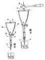
- FIGS. 8A and 8Bare side views of a distractor according to embodiments of the present invention.
- FIGS. 9A-9Care enlarged partial views of the device shown in FIGS. 8A and 8B illustrating assembly of a bridge to a handle, then pivoting of the assembled bridge downwardly according to some embodiments of the present invention.
- FIG. 9Dis a partial side view of the device shown in FIGS. 8A and 8B illustrating the bridge shown in FIGS. 9A-9C being slidably connected to the other handle according to some embodiments of the present invention.
- FIG. 10Ais a side perspective view of a trial according to embodiments of the present invention.
- FIG. 10Bis an enlarged partial side view of the device shown in FIG. 10A .
- FIG. 10Cis an enlarged partial side perspective view of the device shown in FIG. 10A .
- FIG. 11Ais a greatly enlarged partial rear side perspective view of the device shown in FIG. 10A illustrating cutting guide channels/slots according to some embodiments of the present invention.
- FIG. 11Bis a greatly enlarged partial end perspective view of the device shown in FIG. 10A illustrating anterior extending anchoring members according to embodiments of the present invention.
- FIG. 11Cis a greatly enlarged partial side perspective view of the device shown in FIG. 10A illustrating a cutting blade window according to embodiments of the present invention.
- FIGS. 12A and 12Bare side perspective views of the trial being positioned in a target intervertebral space according to embodiments of the present invention.
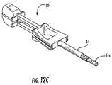
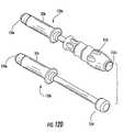
- FIG. 12Cis a side perspective view of a trial with a shaft stem releasably attachable to different handles according to some embodiments of the present invention.
- FIG. 12Dis a side perspective view of two different handles that can releasably attach to the trial shown in FIG. 12C (and/or other instruments) according to embodiments of the present invention.
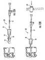
- FIGS. 13A-13Dare side perspective views of serial operations that can be used to cut keelways using the trial according to embodiments of the present invention.
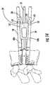
- FIG. 14is a partially translucent side view of two chisels in the fully extended position in upper and lower keelways with the trial in the intervertebral disc (IVD) space according to some embodiments of the present invention.
- FIG. 15Ais a side perspective view of a cutter or chisel according to some embodiments of the present invention.
- FIG. 15Bis a greatly enlarged partial end perspective view of the device shown in FIG. 15A .
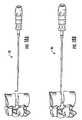
- FIG. 16Ais a side perspective view of ream cutters cooperating with the trial.
- FIG. 16Bis a side view of a ream cutter according to embodiments of the present invention.
- FIG. 16Cis an enlarged partial side end perspective view of the ream cutter shown in FIG. 16B .
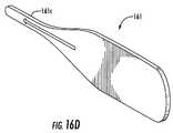
- FIG. 16Dis a side perspective view of a reamer-cleaning tool that can be used to clean a forward cutting portion of a respective reamer according to embodiments of the present invention.
- FIG. 17is a side schematic illustration of a trial with a universal cutter having a fixed stroke distance “X” whereby different trials provide different lengths “D” according to some embodiments of the invention.
- FIGS. 18A and 18Bare side perspective views of a keelway cleaner (hook) according to embodiments of the present invention.
- FIG. 19is a greatly enlarged partial view of the cleaner shown in FIGS. 18A and 18B .
- FIG. 20Ais a top view of an inserter configured to releasably hold a spinal implant according to embodiments of the present invention.
- FIG. 20Bis a side view of the device shown in FIG. 20A .
- FIG. 20Cis a bottom view of the device shown in FIG. 20A .
- FIG. 20Dis a side perspective view of the inserter shown in FIG. 20A .
- FIG. 21Ais a side perspective view of an inserter with implant illustrating the inserter holding the implant according to embodiments of the present invention.
- FIG. 21Bis a bottom view of the device with implant shown in FIG. 21A .
- FIG. 21Cis an end view of the device shown in FIG. 21B .
- FIG. 21Dis a side view of the device with implant shown in FIG. 21A .
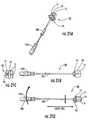
- FIG. 22is a side perspective view of a pusher according to embodiments of the present invention.
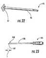
- FIG. 23is a side perspective view of a pilot-hole punch according to embodiments of the present invention.
- FIG. 24Ais a side perspective view of a hex screw holder according to embodiments of the present invention.
- FIG. 24Bis a side view of the device shown in FIG. 24A .
- FIG. 24Cis an end view of the device shown in FIG. 24B .
- FIG. 24Dis a section view taken along line 24 D- 24 D in FIG. 24C .
- FIG. 24Eis an enlarged partial sectional end view of the device shown in FIG. 24D .
- FIG. 25is a side perspective view of a hex screwdriver according to embodiments of the present invention.
- FIG. 26Ais a side view of the device shown in FIG. 25 .
- FIG. 26Bis a partial enlarged view of the operational functional bands shown in FIG. 26A .
- phrases such as “between X and Y” and “between about X and Y”should be interpreted to include X and Y.
- phrases such as “between about X and Y”mean “between about X and about Y.”
- phrases such as “from about X to Y”mean “from about X to about Y.”
- first, second, etc.may be used herein to describe various elements, components, regions, layers and/or sections, these elements, components, regions, layers and/or sections should not be limited by these terms. These terms are only used to distinguish one element, component, region, layer or section from another region, layer or section. Thus, a first element, component, region, layer or section discussed below could be termed a second element, component, region, layer or section without departing from the teachings of the present invention.
- the sequence of operations (or steps)is not limited to the order presented in the claims or figures unless specifically indicated otherwise.
- spinal disc implantand “spinal disc prosthesis” are used interchangeably herein to designate total disc replacements using an implantable total spinal disc replacement prosthesis (rather than a nucleus only) and as such are configured to replace the natural spinal disc of a mammalian subject (for veterinary or medical (human) applications).
- the term “flexible”means that the member can be flexed or bent.
- the keelis flexible but has sufficient rigidity to be substantially self-supporting so as to be able to substantially maintain a desired configuration outside of the body.
- the keelcan include reinforcement to increase its rigidity.
- keelmeans an implant component, feature or member that is configured to be received in a recess or mortise in an adjacent bone to facilitate short and/or long-term fixation and/or to provide twist or torsion resistance in situ.
- meshmeans any flexible material in any form including, for example, knotted, braided, extruded, stamped, knitted, woven or otherwise, and may include a material with a substantially regular foramination pattern and/or irregular foramination patterns.
- macroporesrefers to apertures having at least about a 0.5 mm diameter or width size, typically a diameter or width that is between about 1 mm to about 3 mm, and more typically a diameter or width that is between about 1 mm to about 1.5 mm (the width dimension referring to non-circular apertures).
- the macroporesare larger than the openings or foramina of the mesh substrate. The macropores may promote bony through-growth for increased fixation and/or stabilization over time.
- looprefers to a keel shape in the affected material that has a closed or nearly closed turn or figure.
- the loopcan have its uppermost portion merge into two contacting lower portions or into two proximately spaced apart lower portions.
- foldmeans to bend over and the bend of the fold may have a sharp or rounded edge.
- pleator “fold” refer to doubling material on itself (with or without sharp edges).
- universalmeans that the so-called tool or component thereof can be used with all of the different sized trials or different sized implants, not requiring any trial specific and/or implant specific component.
- FIG. 1illustrates one embodiment of spinal disc implant 10 .
- the implant 10includes at least one keel 15 on each of the upper and lower primary surfaces. Other keel orientations and configurations may also be used.
- the keel 15can extend a distance outward from the implant body between about 2 to about 15 mm, typically between about 6-10 mm.
- the keel 15may be flexible and can provide twist or torsion resistance for the implant 10 and/or facilitate short and long term fixation.
- the keel 15can comprise a mesh fabric material with a thickness between about 0.1-5 mm, typically between about 0.5-3 mm, and more typically between about 1-2 mm.
- the flexible keel 15can include structural reinforcement, such as, for example, coatings, materials or components that add rigidity to the keel 15 .
- the meshis at least partially embedded with crystalline PVA hydrogel to add thickness and rigidity.
- the flexible keels 15can comprise a biocompatible mesh material such as a polyester fabric and the TDR spinal implants may further comprise a crystalline poly(vinyl alcohol) (PVA) hydrogel.
- PVApoly(vinyl alcohol)
- the flexible keelscan be configured to bend (slightly) and/or move side-to-side while having sufficient rigidity to maintain a generally upwardly or downwardly extending orientation outside the body.
- the keel 15is configured to enter a respective channel or mortise formed in an adjacent vertebrae.
- the keel 15is cut part way through in the anterior-posterior direction.
- the channelcan have a relatively shallow depth that is greater than the height of the keel 15 .
- the channelcan have a depth that is between about 5-12 mm.
- the implant 10is substantially covered with at least partially embedded mesh layers and the keel 15 is defined by an outwardly extending looped and/or fold of a mesh layer.
- the mesh layerscan be polyester mesh layers that may be extruded, knitted, braided, woven or otherwise formed into a mesh pattern.
- the meshcomprises a multi-filament fiber(s) that can provide increased strength over conventional polyester material, such as, for example, a polyester mesh multifilament fiber that, for example, can be made out of a High Tenacity Polyester Teraphthalate (HTPET), which typically has a longer molecular chain than conventional polyester material, therefore providing more strength to the mesh than a regular polyester material.
- the meshcan be a high strength mesh that using a ball burst test (ref. ASTM D3787-01) can have a burst value between about 1500-3000N and also a slope of the linear portion of the load/displacement curve of between about 150-300 N/mm.
- FIGS. 1 , 2 A and 2 Bshow that the implant 10 can include a skirt 14 (which can also be described as a tab), which may be reinforced with crystalline molded PVA hydrogel material, to provide a means for attaching to vertebral bodies.
- a skirt 14which can also be described as a tab
- the skirt 14can be between about 1-4 mm thick, typically about 2 mm thick.
- each of the mesh layerscan be about 0.75 mm thick.
- the additional thickness of the skirt 14can be provided by the molded PVA material that embeds the layers forming the skirt material 14 .
- a surgical instrument medical kit 100can be used to select the correct implant size and/or shape and place the implant 10 in the body.
- the medical kit 100can include one or more of the following components, which in particular embodiments, can be arranged in “universal” and size specific trays and/or packaged with an implant 10 as will be discussed further below:
- AKTAccess Window Tool
- Discectomy Width Template (DWT) 30Discectomy Width Template
- Screw Holder 110
- Screwdriver 120
- Second Releasable Handle 150 bSecond Releasable Handle 150 b.
- the implant 10can be made available in a range of different anterior-posterior (AP) sizes with an associated different keel height (the dimensions shown in mm), such as, for example, S, M, L, XL.
- APanterior-posterior
- keel heightthe dimensions shown in mm
- Each subset of differently sized implants, S, M, L, XLcan have differing dimensions associated with one or more of anterior height (AH), posterior height (PH), keel height (KH) and wedge angle (WA).
- AHanterior height
- PHposterior height
- KHkeel height
- WAwedge angle
- the medium and large implantsmay have a greater number of size variations and/or combinations of variations than the small and extra large versions.
- the implantsmay be alternatively provided in other categories of sizes and/or other dimensions.
- the implant 10may be custom-made for a particular patient. See, e.g., co-assigned, co-pending, U.S. application Ser. No. 11/753,755, the contents of which are hereby incorporated by reference as if recited in full herein. As such, some of the instruments defined above may be optional. Similarly, where alternate fixation techniques are used, bone screw instruments may not be required.
- the surgical implantation methodologycan be described by the following general steps. Incision and approach to lumbar spine (Step 1 ). Use the AWT 20 to confirm sufficient approach channel (Step 2 ). Insert the DWT 30 to mark the space for disc removal (Step 3 ). Prepare the intervertebral disc space (Step 4 ). Insert the Spreader/Distractor 40 (Step 5 ). Choose an appropriate trial 50 size (Step 6 ) (may include trying several different trials). Insert the trial 50 (Step 7 ). The trials can perform a supplemental distraction as the space may have a tendency to partially close or collapse after the primary distractor is removed. Cut with the chisels 60 a , 60 b (Step 8 ).
- Step 9Cut with the reamers 70 a , 70 b (Step 9 ). Clean the chiseled slot with the hook 80 (Step 10 ). Insert the implant 10 (Step 11 ).
- the implantcan be forced into position and can also act as a supplemental distractor after the trial is removed to open the disc space to receive the implant without requiring additional tooling to open the space to position the implant 10 (Step 12 ).
- FIGS. 5A-5Billustrate an exemplary AWT 20 with a handle 22 on one end portion and a flat or planar plate 21 on the other.
- the plate 21corresponds to the access window desired by the orthopedic surgeon.
- One AWT 20can be provided or made available for discs of each AP diameter (S, M, L, XL) since the access window for discs of each AP diameter is different.
- FIGS. 6A-6C and 7illustrate an exemplary DWT 30 .
- the DWT 30includes a shield 31 and an outwardly projecting pin 32 on one end connected to a shaft 33 with a handle 34 on the other end.
- the pin 32inserts into the disc prior to discectomy.
- the pin 32can have a length “L” of between about 10-30 mm, typically about 20 mm, and a diameter of between about 1-3 mm, typically about 1.8 mm. This allows the surgeon to determine the patient's midline via visualization, such as via X-Ray, by comparing the pin location relative to anatomical features.
- the shield 31can have an arcuate shape and serve as a stop to limit over-insertion of the pin 32 posteriorly.
- the width “W” of the shield 31is a template that defines the width of disc to be cleared from the disc space during the discectomy.
- the DWT 30can be provided in different heights “H”, such as about 13 mm for S, about 15 mm for M, and about 17 mm for L and XL.
- One DWT 30can be provided or made available for discs of each AP diameter, as the discectomy width for discs of each AP diameter is different.
- the overall length of the DWT 30can be between about 100-300 mm, typically about 200 mm.
- the intervertebral spacecan be prepared with conventional instruments as is well known to those of skill in the art.
- a distractor 40(also known as a spreader) can be used to spread the vertebral bodies adjacent the target disc space.
- the distractor 40can be any conventional distractor. See, e.g., U.S. Pat. No. 7,081,118, the contents of which are hereby incorporated by reference as if recited in full herein.
- the distractor 40can include tip blade portions 41 that remain parallel during spreading, handles 42 1 , 42 2 , a bridge 44 and a hammer engaging member 46 on the bridge 44 .
- the distractor 40includes a mechanical linkage assembly 47 that engages a spring-loaded lock (nut) 48 that can lock the distractor blades 41 to any open position.
- the spring 49can reside between the handles 42 1 , 42 2 .
- the blades 41 and the handles 42 1 , 42 2can be removably attached to opposing end portions of the linkage 47 .
- the distractor 40can perform parallel distraction.
- the bridge 44can be removably attached to the handles 42 1 , 42 2 . As shown, the bridge 44 can be slidably attached to one handle 42 1 , pivoted down, then slidably attached to the other handle 42 2 .
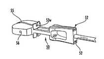
- FIGS. 10A-10Cillustrate an exemplary trial 50 .
- the trial 50includes a shaft 51 that holds a cutter guiding slot 52 , an implant member 54 with bearing surfaces 54 s , and a fixed AP-stop member 53 with a cutting window 53 w .
- the trial 50can include a handle 50 h that can be configured as a removable trial handle/shaft 150 a as shown in FIG. 12C .
- the handle/shaft 150 acan comprise a sterilizable material, such as silicone, for a resusable instrument.
- the implant member 54can also include an aperture for positional control under image visualization, such as X-ray.
- the trial 50can also be an integrated fixed assembly.
- the implant bearing surfaces 54 scan include a shallow clearance groove 55 .
- the optional clearance groove 55does not function as a cutting “guide” and may be provided in the bearing surface 54 s of the trial 50 to allow a lowermost or uppermost portion of the respective chisel 60 a , 60 b and/or reamer 70 a , 70 b to pass thereabove or therebelow.
- the shallow groove 55(e.g., not contact slot) may be less than about 0.5 mm deep, typically about 0.25 mm deep.
- the trial 50has a shaft 51 with an upper guiding slot or channel 52 for the chisel 60 a and reamer 70 a and a lower guiding slot or channel 52 for the chisel 60 b and the reamer 70 b .
- the guiding slots 52reside on the shaft 51 of the trial 50 , axially spaced apart from the stop 53 and the trial implant portion 54 (they are not on the bearing surface of the trial).
- the cutting guide slots 52can be held by respective ramps 58 ; the upper ramp 58 declines toward the superior surface and the lower ramp 58 inclines toward the inferior surface of the trial implant portion 54 .
- the trial 50 implant portion 54can have 3D convex contours on the superior and inferior bearing surfaces 54 s of the trial, substantially matched to average patient anatomies and disc geometries.
- the trials 50can be provided in the same implant widths with sizes varied in other dimensions.
- the trials 50can have a one-to-one correspondence with the corresponding prostheses: one trial implant member portion 54 equals one implantable disc 10 (see, e.g., FIG. 4B ) and the shapes substantially correspond to each other (e.g., the size and convexities of the superior and inferior surfaces of the trial corresponds to the selected spinal implant).
- trials 50may be adjustable, or can be “built”, or are variable by one parameter only (such as height).
- the trial 50 (and implant 10 )can each function as a supplemental distractor during use to open the target disc space which may partially collapse and/or partially close after removal of the primary distractor 40 . That is, the mallet can force the trial 50 (and implant) into position and thereby force the adjacent vertebral bodies further apart to snugly receive the trial 50 (and subsequently the implant 10 ) without requiring the use of any additional instruments to maintain the disc space during trialing or implanting (e.g., the trial and implant are self-distracting).
- FIGS. 11B and 11Cillustrate that the stop 53 can include anchoring portions 57 such as pins or teeth or other features that extend toward the trial implant portion 54 that can engage and/or anchor to local vertebrae.
- the anchoring portions 57comprise two outwardly extending teeth, one on each side of the window 53 w to facilitate the trial biting into and/or engaging the anterior side of the vertebral bodies for the purpose of limiting motion of the trial and/or maintaining trial position during the chiseling and reamer steps.
- FIG. 11Ashows that the lead in portions 52 i of the slots 52 can be configured with a geometry that snugly matably engages that of a corresponding portion of the cutters (chisel and reamer) for positive orientation and alignment during cutting.
- FIG. 11Cillustrates that the window 53 w can provide the geometric lead-in shapes for the cutting blades ( 60 a , 70 a ) in a lateral and a caudal-cranial direction and that the geometry can be configured to snugly and/or matably receive the lower or upper leading ends of the blades (depending on if an upper or lower keelway is being cut) ( 61 s , 71 s , FIGS. 15A , 16 A).
- FIGS. 12A and 12Billustrate the trial 50 being inserted into position according to some embodiments of the present invention.
- a mallet 159can be used to advance the implant portion 54 into position with the upper and lower stops 53 resting against the outer surfaces of the respective vertebral bones.
- FIG. 12Cillustrates a trial 50 with a shaft 51 having a shaft stem 51 s that releasably engages different handles 50 h .
- the trial stem 51 scan serially attach to first and second releasably attachable handles 150 a , 150 b .
- the trial 50can also attach to the second handle 150 b , to allow for the mallet 159 to cooperate with the second handle for ease of extraction of the trial 50 .
- the first handle 150 acan have an end portion that cooperates with the mallet 159 while the second handle 150 b can have an end portion that allows for cooperation with a mallet in the reverse direction from that of the first handle 150 a .
- the attachment means between stem 51 s and engaging end 150 e of the handle 50 hcan be any suitable means, including bayonet, frictional press-fit, threads, or the like.
- the first handle 150 ahas a rubber grip handle 153 with a rigid end 153 e for engaging the mallet 159 .
- the other handle 150 bcan have a knob 154 for “hammering” out or extracting the trial 50 from the disc space (e.g., for removing the trial rather than inserting the trial as per handle 150 a ).
- one or both of the handles 150 a , 150 bcan releasably attach to other instruments and the other instruments can have a stem 51 s similar to that shown with respect to the trial 50 in FIG. 12C .
- the pusher 95 and inserter 90can all attach to the first handle 150 a.
- FIGS. 13A-13Dillustrate the use of a cutter or chisel blades 60 a , 60 b to cut the keelways or mortises in the vertebral bones.
- the cutting bladee.g., chisel and/or reamer
- the cutting bladeextends into intevertebral bone and a lower portion thereof may travel over the bearing surface 54 s in the intevertebral space, but typically does not contact the bearing surface 54 s of the trial 50 .
- each trial 50can incorporate a unique geometry relative to the geometry of the other trials in the set which, when used with a common “universal” chisel and/or “universal” reamer or other “universal” cutting device, can yield a unique keelway height and depth cut into the vertebral bodies.
- each trial 50can incorporate a fixed stop location 59 that cooperates with a fixed stop segment of the cutter, such as chisel stop portion 63 and reamer stop portion 73 ( FIGS. 13B , 16 A) on the respective chisel and reamer.
- the position of the fixed stop location 59can be defined by the ramp 58 . As shown in FIGS.
- the fixed ramp stop location 59can be proximate a lead-in portion of the ramp 58 and defined by the geometry of the slot 52 and geometry of the stop portion 63 , 73 of the respective cutter.
- the fixed stop location 59may be positioned in other locations, such as, for example, on the window 53 or at a different location along the ramp 58 . It is noted that although chisels and reamers are described as suitable bone cutting devices, saws (blades) or other devices may also or alternatively be used.
- each trial 50can be configured to be different to allow for different cut heights and depths into the target vertebral body.
- the plane of the ramp 58can be considered to be “sunken” relative to the bearing surface 54 s of the trial.
- Each trial 50can incorporate a different sunken depth of this plane, which allows for a unique keelway height to be cut into the vertebral body.
- chisels 60 a , 60 bare used to cut the desired keelways.
- the cuttingcan be carried out serially as shown in FIGS. 13A-13D , with the top cutter 60 a typically used first and kept in position until the bottom cutter 60 b is extended to stabilize the trial 50 as shown in FIG. 14 .
- the bottom cutter (e.g., chisel) 60 bmay be used first, with the upper cutter 60 a following behind.
- the schematic illustration of the vertebrae and the extended cutters 60 a , 60 b in FIG. 14is not to scale (and XL trial is shown); however, a smaller trial may be more appropriate in the vertebrae shown.
- FIGS. 15A and 15Bshow an example of a chisel 60 a , 60 b .
- the leading edge 62can be beveled or have a chamfer 62 b .
- a series of apertures 64can be used to trap or remove chiseled bone.
- the blade 60 a , 60 bcan also include a segment with a formed ledge 66 located axially rearward of the cutting portion of the chisel 61 that matably engages slot 52 in the ramp 58 of the trial 50 .
- the formed ledge 66typically does not extend through window 53 w during cutting as only the cutting end portion 61 extends into the vertebral bone to cut the keelway.
- FIGS. 16A-16Cillustrate a similar configuration for the reamer 70 a , 70 b .
- the reamers 70 a , 70 bare primarily used to “square” up the keelways, apertures are not required. Indeed, the reamers 70 a , 70 b may not be required in some embodiments as the chisels 60 a , 60 b (or other cutting devices) may form sufficiently open keelways (particularly for flexible keels).
- the cutting end portion 72 of the reamers 70 a , 70 bmay be configured with a beveled edge 72 b and may include a small gap 72 g or mismatch between two cutting blades 74 , 75 to allow bone to enter therein. As shown in FIG.
- a thin reamer-cleaning tool 161 with a cleaning segment 161 ccan be inserted into the gap 72 g to clean the reamer.
- the blade 70 a , 70 bcan also include a segment with a formed ledge 76 located axially rearward of the cutting portion of the reamer 71 that matably engages slot 52 in the ramp 58 of the trial 50 .
- the formed ledge 76typically does not extend through window 53 w during cutting as only the cutting end portion 72 extends into the vertebral bone to cut the keelway.
- FIG. 16Aillustrates that the top reamer 70 a slides through the guides 52 to ream the keelway 10 k , and remains in position while the bottom reamer 70 b slides through its respective guide 72 to ream the lower keelway.
- the cutting ends (blades) of the reamer 70 a , 70 b and chisel 60 a , 60 bcan be configured to be replaceable with the devices being multi-use/reusable after sterilization.
- the order of cuttingis typically to (a) use one chisel cutter 60 a and leave the chisel cutter 60 a in position, (b) insert the second chisel cutter 60 b , (c) remove the second cutter 60 b , (d) insert the first reamer 70 a while the first cutter 60 a is still in position, (e) remove the first chisel cutter 60 a , and (f) insert the second reamer 70 b while the first reamer 70 a is still in position.
- a universal chisel 60 a , 60 b and/or reamer 70 a , 70 bcan be used with any of the trials 50 .
- each trialcan have a different distance “D” that corresponds the distance between the anterior portion or side of the trial implant 54 and stop 53 and the cutting blade stop location 59 on the respective ramp 58 ; however, the overall length “X” can be substantially constant for all of the trials 50 , allowing the use of a common or “universal” chisel and/or reamer. That is, the trials 50 can have different lengths from a proximal side of the ramp 59 to an anterior stop 59 of the trial thereby allowing the use of a common reamer and/or chisel for each of the various trials.
- a clearing hook 80can be used to clear debris that remains in the keelways.
- the clearing hook 80is not designed as a scraper/cutter.
- the clearing hook 80can have a shaft 84 that merges into a handle 85 at one end and that merges into a substantially planar segment 82 that is substantially orthogonal to the primary shaft 84 and has rounded outer edges 83 .
- the width of the rounded edgecan be between about 2-3 mm.
- the inserter 90has an implant holder head 90 h .
- the head 90 hhas a skirt channel 91 that releasably engages the skirt 14 of implant 10 ( FIGS. 1 , 2 A).
- the inserter 90is configured to allow a user to slide the instrument 90 sideways to release the implanted product 10 (once implanted in the IVD space), or to torque it over (as with a claw hammer working on a nail) to pry the instrument 90 away from the implanted device 10 .
- One inserter 10can be configured to hold and implant al of the disc sizes of a substantially common AP diameter.
- the inserter head 90 hcan be formed from an elastomeric and/or metallic material.
- the inserter 90is typically oriented so that a closed floor 92 of the skirt channel 91 is under the lower portion of the bottom skirt 14 .
- the handle 90 h of the inserter 90can be rotated to rotate the inserter about the implant 10 (shown by the arrow proximate the handle in FIG. 21D ) to release the inserter 90 from the implant 10 , leaving the implant 10 in position.
- the release of the implant 10 from the inserter 10can use rotation due to the flexibility of the skirt 14 .
- the implant 10can be released by sliding the inserter 90 downward (which in this case does require that the skirt flex)—as indicated by the down arrow proximate the channel 91 in FIG. 21D .
- the latter operationmay employ some clearance for the inserter, which may not be possible in some applications due to the typically small size of the surgical windows.
- FIG. 22illustrates that a pusher 95 can be used to further push the implant 10 into a desired position in the target IVD space.
- the pusher 95includes a shaft 96 and a shield 97 that pushes against the implant 10 .
- FIG. 23illustrates a pilot hole punch 105 .
- the punch 105includes a shaft and a sharp punch end 107 .
- the punch length “L” of the punch end 107is greater than the thickness of the implant skirt 14 and the thickness of the cortical layer of bone to ensure that the cortical layer is punched through.
- the punch length “L”can be between about 5-15 mm, which is typically longer than the penetrating length, which is typically between about 3-10 mm (so as to be able to penetrate the skirt 14 ).
- the punch end 107merges into a fixed stop 108 to ensure that the punch 107 is not over-inserted into the bone posteriorly.
- the punch 105can be used to insert apertures into the skirt and/or underlying bone. Typically, four holes are punched into the bone and skirt for receiving anchoring members such as bone screws, but the skirt 14 may be preformed with the holes.
- FIGS. 24A-24Eillustrate a screw holder 110 that holds a screw at a distal screw cavity portion 112 .
- the screw holder 110cooperates with a hex screwdriver 120 ( FIG. 25 , FIGS. 26A , 26 B). That is, the shaft 121 of the hex screwdriver is configured to reside in a channel 111 in the screw holder 110 to allow the screwdriver 120 to advance and rotate to tighten a target screw held in cavity 112 against the skirt 14 ( FIG. 1 ) and into underlying bone, while the screw is positively retained by the holder 110 .
- the holder 110can be disengaged when the screw is partially engaged with bone. As shown in FIGS.
- the screwdriver 120can incorporate color-coded bands 123 . At least one of the bands 123 shows through a window or is otherwise visible when in the screw holder 110 for each position of the holder 110 relative to the screwdriver: e.g., Load, Lock, Unlock, although other words, indicia, such as arrows or combinations thereof can be used to indicate the desired operation (e.g., Assemble, Lock, Release).
- the holder 110With the hex head of the screwdriver 120 inserted into the hex receptacle of the screw, the holder 110 holds the screw on the outer diameter of the head.
- a usercan turn the screwdriver 120 in the holder 110 to select the desired operation to carry out the associated operation: for example, to load a screw into the device 110 , lock the screw in the device 110 , then unlock the holder 110 after the screw is assembled to the implant 10 .
- the distractor 40(and its components, e.g., blades, handles, bridge) may be provided as a single universal device in the medical kit.
- the pusher 95 , mallet 159 , pilot hole punch 105 , screwdriver 120 and holder 110may be provided as universal components (e.g., a single one of each).
- Screws, where used,can be provided in at least two sizes 122 a , 122 b ( FIG. 3 ) to allow for an increased size that can be used where the smaller one is stripped.
- the screws 122 a , 122 bcan be packaged and/or provided with the implant 10 or with the instrument kit 100 .
- a single removable trial handle/shaft 150 acan be provided to mate with all of the trials 50 .
- the inserter 90can be provided in S, M, L, and XL.
- a universal medical tray(not shown) can be provided that packages the universal instruments together. Additionally, for convenience, pre-assembled trays of small instruments, medium instruments, large instruments, and extra large instruments can be selected and provided, each for a target site(s) such as L4/L5.
- the trials 50 and implants 10can be in 23 different sizes and configurations, and they can be sub-grouped into the S, M, L and XL categories for easier selection and/or use by a clinician.
Landscapes
- Health & Medical Sciences (AREA)
- Orthopedic Medicine & Surgery (AREA)
- Engineering & Computer Science (AREA)
- Biomedical Technology (AREA)
- Transplantation (AREA)
- Life Sciences & Earth Sciences (AREA)
- General Health & Medical Sciences (AREA)
- Veterinary Medicine (AREA)
- Oral & Maxillofacial Surgery (AREA)
- Heart & Thoracic Surgery (AREA)
- Public Health (AREA)
- Animal Behavior & Ethology (AREA)
- Cardiology (AREA)
- Vascular Medicine (AREA)
- Neurology (AREA)
- Physical Education & Sports Medicine (AREA)
- Surgery (AREA)
- Dentistry (AREA)
- Nuclear Medicine, Radiotherapy & Molecular Imaging (AREA)
- Medical Informatics (AREA)
- Molecular Biology (AREA)
- Prostheses (AREA)
Abstract
Description
Claims (10)
Priority Applications (1)
| Application Number | Priority Date | Filing Date | Title |
|---|---|---|---|
| US12/101,390US8172848B2 (en) | 2007-04-27 | 2008-04-11 | Surgical instruments for spinal disc implants and related methods |
Applications Claiming Priority (2)
| Application Number | Priority Date | Filing Date | Title |
|---|---|---|---|
| US91447107P | 2007-04-27 | 2007-04-27 | |
| US12/101,390US8172848B2 (en) | 2007-04-27 | 2008-04-11 | Surgical instruments for spinal disc implants and related methods |
Publications (2)
| Publication Number | Publication Date |
|---|---|
| US20080269756A1 US20080269756A1 (en) | 2008-10-30 |
| US8172848B2true US8172848B2 (en) | 2012-05-08 |
Family
ID=39887878
Family Applications (1)
| Application Number | Title | Priority Date | Filing Date |
|---|---|---|---|
| US12/101,390Expired - Fee RelatedUS8172848B2 (en) | 2007-04-27 | 2008-04-11 | Surgical instruments for spinal disc implants and related methods |
Country Status (1)
| Country | Link |
|---|---|
| US (1) | US8172848B2 (en) |
Cited By (36)
| Publication number | Priority date | Publication date | Assignee | Title |
|---|---|---|---|---|
| US20100280620A1 (en)* | 2009-04-15 | 2010-11-04 | Marc Reichen | Trial implant assembly |
| US9622805B2 (en) | 2015-08-14 | 2017-04-18 | Treace Medical Concepts, Inc. | Bone positioning and preparing guide systems and methods |
| US9662123B2 (en) | 2014-07-31 | 2017-05-30 | Amendia, Inc. | Vertical cutter and method of use |
| US9687250B2 (en) | 2015-01-07 | 2017-06-27 | Treace Medical Concepts, Inc. | Bone cutting guide systems and methods |
| US10342590B2 (en) | 2015-08-14 | 2019-07-09 | Treace Medical Concepts, Inc. | Tarsal-metatarsal joint procedure utilizing fulcrum |
| US10512470B1 (en) | 2016-08-26 | 2019-12-24 | Treace Medical Concepts, Inc. | Osteotomy procedure for correcting bone misalignment |
| US10524808B1 (en) | 2016-11-11 | 2020-01-07 | Treace Medical Concepts, Inc. | Devices and techniques for performing an osteotomy procedure on a first metatarsal to correct a bone misalignment |
| US10555757B2 (en) | 2014-07-15 | 2020-02-11 | Treace Medical Concepts, Inc. | Bone positioning and cutting system and method |
| US10575862B2 (en) | 2015-09-18 | 2020-03-03 | Treace Medical Concepts, Inc. | Joint spacer systems and methods |
| US10653467B2 (en) | 2015-05-06 | 2020-05-19 | Treace Medical Concepts, Inc. | Intra-osseous plate system and method |
| US10849631B2 (en) | 2015-02-18 | 2020-12-01 | Treace Medical Concepts, Inc. | Pivotable bone cutting guide useful for bone realignment and compression techniques |
| US10849663B2 (en) | 2015-07-14 | 2020-12-01 | Treace Medical Concepts, Inc. | Bone cutting guide systems and methods |
| US10874446B2 (en) | 2015-07-14 | 2020-12-29 | Treace Medical Concepts, Inc. | Bone positioning guide |
| US10939939B1 (en) | 2017-02-26 | 2021-03-09 | Treace Medical Concepts, Inc. | Fulcrum for tarsal-metatarsal joint procedure |
| US11278337B2 (en) | 2015-08-14 | 2022-03-22 | Treace Medical Concepts, Inc. | Tarsal-metatarsal joint procedure utilizing fulcrum |
| US11583323B2 (en) | 2018-07-12 | 2023-02-21 | Treace Medical Concepts, Inc. | Multi-diameter bone pin for installing and aligning bone fixation plate while minimizing bone damage |
| US11596443B2 (en) | 2018-07-11 | 2023-03-07 | Treace Medical Concepts, Inc. | Compressor-distractor for angularly realigning bone portions |
| US11607250B2 (en) | 2019-02-13 | 2023-03-21 | Treace Medical Concepts, Inc. | Tarsal-metatarsal joint procedure utilizing compressor-distractor and instrument providing sliding surface |
| US11622797B2 (en) | 2020-01-31 | 2023-04-11 | Treace Medical Concepts, Inc. | Metatarsophalangeal joint preparation and metatarsal realignment for fusion |
| US11627954B2 (en) | 2019-08-07 | 2023-04-18 | Treace Medical Concepts, Inc. | Bi-planar instrument for bone cutting and joint realignment procedure |
| USD1011524S1 (en) | 2022-02-23 | 2024-01-16 | Treace Medical Concepts, Inc. | Compressor-distractor for the foot |
| US11890039B1 (en) | 2019-09-13 | 2024-02-06 | Treace Medical Concepts, Inc. | Multi-diameter K-wire for orthopedic applications |
| US11889998B1 (en) | 2019-09-12 | 2024-02-06 | Treace Medical Concepts, Inc. | Surgical pin positioning lock |
| US11931106B2 (en) | 2019-09-13 | 2024-03-19 | Treace Medical Concepts, Inc. | Patient-specific surgical methods and instrumentation |
| US11986251B2 (en) | 2019-09-13 | 2024-05-21 | Treace Medical Concepts, Inc. | Patient-specific osteotomy instrumentation |
| US12004789B2 (en) | 2020-05-19 | 2024-06-11 | Treace Medical Concepts, Inc. | Devices and techniques for treating metatarsus adductus |
| USD1051382S1 (en) | 2022-02-23 | 2024-11-12 | Treace Medical Concepts, Inc. | Lesser metatarsal cut guide |
| US12161371B2 (en) | 2021-01-18 | 2024-12-10 | Treace Medical Concepts, Inc. | Contoured bone plate with locking screw for bone compression, particularly across a tarsometatarsal joint |
| USD1057155S1 (en) | 2022-02-23 | 2025-01-07 | Treace Medical Concepts, Inc. | Lesser metatarsal cut guide with parallel cut faces |
| US12193683B2 (en) | 2021-05-20 | 2025-01-14 | Treace Medical Concepts, Inc. | Cut guide with integrated joint realignment features |
| USD1068078S1 (en) | 2023-02-08 | 2025-03-25 | Treace Medical Concepts, Inc. | Handle for an orthopedic instrument |
| USD1068077S1 (en) | 2023-02-08 | 2025-03-25 | Treace Medical Concepts, Inc. | Orthopedic rasp for preparing an intercuneiform joint |
| USD1075012S1 (en) | 2022-02-23 | 2025-05-13 | Treace Medical Concepts, Inc. | Metatarsal lateral release instrument |
| US12310603B2 (en) | 2021-02-18 | 2025-05-27 | Treace Medical Concepts, Inc. | System and technique for metatarsal realignment with reduced incision length |
| USD1079011S1 (en) | 2022-02-23 | 2025-06-10 | Treace Medical Concepts, Inc. | Metatarsal cut guide with parallel cut faces |
| US12440250B2 (en) | 2024-02-05 | 2025-10-14 | Treace Medical Concepts, Inc. | Multi-diameter K-wire for orthopedic applications |
Families Citing this family (41)
| Publication number | Priority date | Publication date | Assignee | Title |
|---|---|---|---|---|
| US8597360B2 (en) | 2004-11-03 | 2013-12-03 | Neuropro Technologies, Inc. | Bone fusion device |
| US8790403B2 (en)* | 2006-04-20 | 2014-07-29 | K2M, Inc. | Monorail system |
| US7824427B2 (en)* | 2007-01-16 | 2010-11-02 | Perez-Cruet Miquelangelo J | Minimally invasive interbody device |
| US20090088789A1 (en)* | 2007-09-28 | 2009-04-02 | O'neil Michael J | Balloon With Shape Control For Spinal Procedures |
| AU2009205679B2 (en)* | 2008-01-18 | 2013-12-05 | Spinecore, Inc. | Instruments and methods for inserting artificial intervertebral implants |
| US8152846B2 (en)* | 2008-03-06 | 2012-04-10 | Musculoskeletal Transplant Foundation | Instrumentation and method for repair of meniscus tissue |
| EP2337510B1 (en) | 2008-06-25 | 2018-10-31 | Stryker European Holdings I, LLC | Surgical instrumentation for implanting a prothesis |
| US8349015B2 (en) | 2009-02-11 | 2013-01-08 | Howmedica Osteonics Corp. | Intervertebral implant with integrated fixation |
| US9439685B2 (en)* | 2009-05-12 | 2016-09-13 | Bullard Spine, Llc | Multi-layer osteoinductive, osteogenic, and osteoconductive carrier |
| ES2563172T3 (en) | 2009-07-09 | 2016-03-11 | R Tree Innovations, Llc | Flexible intersomatic implant |
| EP2835113B1 (en) | 2009-08-10 | 2016-05-25 | Howmedica Osteonics Corp. | Intervertebral implant with integrated fixation |
| EP2496187B1 (en) | 2009-11-03 | 2016-12-21 | Howmedica Osteonics Corp. | Intervertebral implant with integrated fixation |
| WO2013023096A1 (en) | 2011-08-09 | 2013-02-14 | Neuropro Technologies, Inc. | Bone fusion device, system and method |
| US9358123B2 (en) | 2011-08-09 | 2016-06-07 | Neuropro Spinal Jaxx, Inc. | Bone fusion device, apparatus and method |
| US10420654B2 (en) | 2011-08-09 | 2019-09-24 | Neuropro Technologies, Inc. | Bone fusion device, system and method |
| JP4875220B1 (en)* | 2011-08-10 | 2012-02-15 | 浩太 須田 | Puncture device |
| US9532883B2 (en) | 2012-04-13 | 2017-01-03 | Neuropro Technologies, Inc. | Bone fusion device |
| US10159583B2 (en) | 2012-04-13 | 2018-12-25 | Neuropro Technologies, Inc. | Bone fusion device |
| CA2906531C (en) | 2013-03-15 | 2020-10-06 | Neuropro Technologies, Inc. | Bodiless bone fusion device, apparatus and method |
| US9730802B1 (en)* | 2014-01-14 | 2017-08-15 | Nuvasive, Inc. | Spinal fusion implant and related methods |
| US9456817B2 (en) | 2014-04-08 | 2016-10-04 | DePuy Synthes Products, Inc. | Methods and devices for spinal correction |
| US9498351B2 (en)* | 2014-06-04 | 2016-11-22 | Spine Wave, Inc. | Apparatus for locating the position of a spinal implant during surgery |
| AU2016200179B2 (en) | 2015-01-14 | 2020-09-17 | Stryker European Operations Holdings Llc | Spinal implant with porous and solid surfaces |
| AU2016200195B2 (en) | 2015-01-14 | 2020-07-02 | Vb Spine Us Opco Llc | Spinal implant with fluid delivery capabilities |
| CA2930123A1 (en) | 2015-05-18 | 2016-11-18 | Stryker European Holdings I, Llc | Partially resorbable implants and methods |
| DE102015007540A1 (en)* | 2015-06-16 | 2016-12-22 | Adalbert Missalla | Surgical instrument set |
| EP3195833B1 (en)* | 2016-01-19 | 2022-01-12 | K2M, Inc. | Surgical instrument |
| TW201739427A (en)* | 2016-03-03 | 2017-11-16 | 典型脊骨股份有限公司 | Instruments for interspinous or interlaminar stabilization devices |
| US10231849B2 (en)* | 2016-10-13 | 2019-03-19 | Warsaw Orthopedic, Inc. | Surgical instrument system and method |
| US10729560B2 (en) | 2017-01-18 | 2020-08-04 | Neuropro Technologies, Inc. | Bone fusion system, device and method including an insertion instrument |
| US10213321B2 (en) | 2017-01-18 | 2019-02-26 | Neuropro Technologies, Inc. | Bone fusion system, device and method including delivery apparatus |
| US10111760B2 (en) | 2017-01-18 | 2018-10-30 | Neuropro Technologies, Inc. | Bone fusion system, device and method including a measuring mechanism |
| US10973657B2 (en) | 2017-01-18 | 2021-04-13 | Neuropro Technologies, Inc. | Bone fusion surgical system and method |
| EP3459502B1 (en) | 2017-09-20 | 2024-05-22 | Stryker European Operations Holdings LLC | Spinal implants |
| US11013607B2 (en) | 2017-09-22 | 2021-05-25 | Encore Medical, L.P. | Talar ankle implant |
| EP3501432A1 (en) | 2017-12-20 | 2019-06-26 | Stryker European Holdings I, LLC | Joint instrumentation |
| US11224446B2 (en)* | 2019-06-20 | 2022-01-18 | Imam Abdulrahman Bin Faisal University | Supracondylar bullet sleeve |
| EP4034002B1 (en)* | 2019-09-24 | 2025-09-10 | Simplify Medical Pty Limited | Surgical cutter instrument with trial |
| US11648132B2 (en)* | 2019-09-24 | 2023-05-16 | Adcura, Inc | Surgical instrument for operating spinal implant system with dual axis adjustability and method of operating same |
| BR102020010701A2 (en)* | 2020-05-28 | 2021-12-07 | M3 Health Ind E Comercio De Produtos Medicos Odontologicos E Correlatos S A | Dental and medical device insertion instrument and dental and medical device insertion tool comprising said instrument |
| US12324753B2 (en)* | 2022-10-05 | 2025-06-10 | Warsaw Orthopedic, Inc. | Interbody trial instrument with screw trajectory indicators |
Citations (24)
| Publication number | Priority date | Publication date | Assignee | Title |
|---|---|---|---|---|
| USD245919S (en) | 1976-10-01 | 1977-09-27 | Zimmer, U.S.A. Inc. | Talar resection guide |
| US4759766A (en) | 1984-09-04 | 1988-07-26 | Humboldt-Universitaet Zu Berlin | Intervertebral disc endoprosthesis |
| USD312309S (en) | 1987-11-16 | 1990-11-20 | Michelson Gary K | Lumbar interbody graft driver |
| US5314477A (en) | 1990-03-07 | 1994-05-24 | J.B.S. Limited Company | Prosthesis for intervertebral discs and instruments for implanting it |
| US5401269A (en) | 1992-03-13 | 1995-03-28 | Waldemar Link Gmbh & Co. | Intervertebral disc endoprosthesis |
| US5556431A (en) | 1992-03-13 | 1996-09-17 | B+E,Uml U+Ee Ttner-Janz; Karin | Intervertebral disc endoprosthesis |
| US5899907A (en) | 1991-06-27 | 1999-05-04 | Johnson; Lanny L. | Instrumentation for proximal femoral compaction broaching |
| US6425920B1 (en) | 1999-10-13 | 2002-07-30 | James S. Hamada | Spinal fusion implant |
| US20040143332A1 (en)* | 2002-10-31 | 2004-07-22 | Krueger David J. | Movable disc implant |
| US20040143331A1 (en) | 2001-07-16 | 2004-07-22 | Errico Joseph P. | Intervertebral spacer device having simultaneously engageable angled perimeters for manipulation using a surgical tool |
| US6793658B2 (en) | 2001-04-06 | 2004-09-21 | Society De Fabrication De Material Orthopedique, S.A. | Anterior plating system and method |
| US20040215198A1 (en) | 2003-04-28 | 2004-10-28 | Spine Solutions, Inc. | Instruments and method for preparing an intervertebral space for receiving an artificial disc implant |
| US20050043740A1 (en)* | 2003-08-20 | 2005-02-24 | Haid Regis W. | Technique and instrumentation for preparation of vertebral members |
| US20050055099A1 (en) | 2003-09-09 | 2005-03-10 | Ku David N. | Flexible spinal disc |
| US20050090829A1 (en) | 2003-10-23 | 2005-04-28 | Osteotech, Inc. | Spinal bone chisels |
| US6923813B2 (en) | 2003-09-03 | 2005-08-02 | Kyphon Inc. | Devices for creating voids in interior body regions and related methods |
| US20050288788A1 (en) | 2004-06-25 | 2005-12-29 | Gretchen Dougherty-Shah | Intervertebral implant and associated method |
| US20060064100A1 (en) | 2004-09-23 | 2006-03-23 | Rudi Bertagnoli | Adjustable cutting of cutout in vertebral bone |
| WO2006033067A2 (en) | 2004-09-23 | 2006-03-30 | Spine Solutions Inc. | System and method for an intervertebral implant |
| US20060129160A1 (en)* | 2003-03-13 | 2006-06-15 | Sdgi Holdings, Inc. | Vertebral endplate preparation tool kit |
| US7081118B2 (en) | 2002-08-22 | 2006-07-25 | Helmut Weber | Medical tool |
| US7128760B2 (en) | 2001-03-27 | 2006-10-31 | Warsaw Orthopedic, Inc. | Radially expanding interbody spinal fusion implants, instrumentation, and methods of insertion |
| US20070179621A1 (en) | 2006-01-25 | 2007-08-02 | Spinemedica Corporation | Spinal disc implants with flexible keels and methods of fabricating implants |
| US20070276501A1 (en) | 2006-05-25 | 2007-11-29 | Spinemedica Corp. | Patient-specific spinal implants and related systems and methods |
- 2008
- 2008-04-11USUS12/101,390patent/US8172848B2/ennot_activeExpired - Fee Related
Patent Citations (26)
| Publication number | Priority date | Publication date | Assignee | Title |
|---|---|---|---|---|
| USD245919S (en) | 1976-10-01 | 1977-09-27 | Zimmer, U.S.A. Inc. | Talar resection guide |
| US4759766A (en) | 1984-09-04 | 1988-07-26 | Humboldt-Universitaet Zu Berlin | Intervertebral disc endoprosthesis |
| USD312309S (en) | 1987-11-16 | 1990-11-20 | Michelson Gary K | Lumbar interbody graft driver |
| US5314477A (en) | 1990-03-07 | 1994-05-24 | J.B.S. Limited Company | Prosthesis for intervertebral discs and instruments for implanting it |
| US5899907A (en) | 1991-06-27 | 1999-05-04 | Johnson; Lanny L. | Instrumentation for proximal femoral compaction broaching |
| US5401269A (en) | 1992-03-13 | 1995-03-28 | Waldemar Link Gmbh & Co. | Intervertebral disc endoprosthesis |
| US5556431A (en) | 1992-03-13 | 1996-09-17 | B+E,Uml U+Ee Ttner-Janz; Karin | Intervertebral disc endoprosthesis |
| US6425920B1 (en) | 1999-10-13 | 2002-07-30 | James S. Hamada | Spinal fusion implant |
| US6436101B1 (en) | 1999-10-13 | 2002-08-20 | James S. Hamada | Rasp for use in spine surgery |
| US7128760B2 (en) | 2001-03-27 | 2006-10-31 | Warsaw Orthopedic, Inc. | Radially expanding interbody spinal fusion implants, instrumentation, and methods of insertion |
| US6793658B2 (en) | 2001-04-06 | 2004-09-21 | Society De Fabrication De Material Orthopedique, S.A. | Anterior plating system and method |
| US20040143331A1 (en) | 2001-07-16 | 2004-07-22 | Errico Joseph P. | Intervertebral spacer device having simultaneously engageable angled perimeters for manipulation using a surgical tool |
| US7081118B2 (en) | 2002-08-22 | 2006-07-25 | Helmut Weber | Medical tool |
| US20040143332A1 (en)* | 2002-10-31 | 2004-07-22 | Krueger David J. | Movable disc implant |
| US20060116768A1 (en) | 2002-10-31 | 2006-06-01 | Krueger David J | Movable disc implant |
| US20060129160A1 (en)* | 2003-03-13 | 2006-06-15 | Sdgi Holdings, Inc. | Vertebral endplate preparation tool kit |
| US20040215198A1 (en) | 2003-04-28 | 2004-10-28 | Spine Solutions, Inc. | Instruments and method for preparing an intervertebral space for receiving an artificial disc implant |
| US20050043740A1 (en)* | 2003-08-20 | 2005-02-24 | Haid Regis W. | Technique and instrumentation for preparation of vertebral members |
| US6923813B2 (en) | 2003-09-03 | 2005-08-02 | Kyphon Inc. | Devices for creating voids in interior body regions and related methods |
| US20050055099A1 (en) | 2003-09-09 | 2005-03-10 | Ku David N. | Flexible spinal disc |
| US20050090829A1 (en) | 2003-10-23 | 2005-04-28 | Osteotech, Inc. | Spinal bone chisels |
| US20050288788A1 (en) | 2004-06-25 | 2005-12-29 | Gretchen Dougherty-Shah | Intervertebral implant and associated method |
| US20060064100A1 (en) | 2004-09-23 | 2006-03-23 | Rudi Bertagnoli | Adjustable cutting of cutout in vertebral bone |
| WO2006033067A2 (en) | 2004-09-23 | 2006-03-30 | Spine Solutions Inc. | System and method for an intervertebral implant |
| US20070179621A1 (en) | 2006-01-25 | 2007-08-02 | Spinemedica Corporation | Spinal disc implants with flexible keels and methods of fabricating implants |
| US20070276501A1 (en) | 2006-05-25 | 2007-11-29 | Spinemedica Corp. | Patient-specific spinal implants and related systems and methods |
Cited By (87)
| Publication number | Priority date | Publication date | Assignee | Title |
|---|---|---|---|---|
| US20100280620A1 (en)* | 2009-04-15 | 2010-11-04 | Marc Reichen | Trial implant assembly |
| US9078771B2 (en)* | 2009-04-15 | 2015-07-14 | DePuy Synthes Products, Inc. | Trial implant assembly |
| US11937849B2 (en) | 2014-07-15 | 2024-03-26 | Treace Medical Concepts, Inc. | Bone positioning and cutting system and method |
| US11147590B2 (en) | 2014-07-15 | 2021-10-19 | Treace Medical Concepts, Inc. | Bone positioning and cutting system and method |
| US10945764B2 (en) | 2014-07-15 | 2021-03-16 | Treace Medical Concepts, Inc. | Bone positioning and cutting system and method |
| US11497528B2 (en) | 2014-07-15 | 2022-11-15 | Treace Medical Concepts, Inc. | Bone positioning and cutting system and method |
| US12349941B2 (en) | 2014-07-15 | 2025-07-08 | Treace Medical Concepts, Inc. | Bone positioning and cutting system and method |
| US11523845B2 (en) | 2014-07-15 | 2022-12-13 | Treace Medical Concepts, Inc. | Bone positioning and cutting system and method |
| US10555757B2 (en) | 2014-07-15 | 2020-02-11 | Treace Medical Concepts, Inc. | Bone positioning and cutting system and method |
| US11771467B2 (en) | 2014-07-15 | 2023-10-03 | Treace Medical Concepts, Inc. | Bone positioning and cutting system and method |
| US10172628B2 (en) | 2014-07-31 | 2019-01-08 | Amendia, Inc. | Vertical cutter and method of use |
| US9918722B2 (en) | 2014-07-31 | 2018-03-20 | Amendia, Inc. | Vertical cutter and method of use |
| US9662123B2 (en) | 2014-07-31 | 2017-05-30 | Amendia, Inc. | Vertical cutter and method of use |
| US12023048B2 (en) | 2014-07-31 | 2024-07-02 | Spinal Elements, Inc. | Vertical cutter and method of use |
| US9687250B2 (en) | 2015-01-07 | 2017-06-27 | Treace Medical Concepts, Inc. | Bone cutting guide systems and methods |
| US11786257B2 (en) | 2015-01-07 | 2023-10-17 | Treace Medical Concepts, Inc. | Bone cutting guide systems and methods |
| US10603046B2 (en) | 2015-01-07 | 2020-03-31 | Treace Medical Concepts, Inc. | Bone cutting guide systems and methods |
| US10561426B1 (en) | 2015-01-07 | 2020-02-18 | Treace Medical Concepts, Inc. | Bone cutting guide systems and methods |
| US10888335B2 (en) | 2015-01-07 | 2021-01-12 | Treace Medical Concepts, Inc. | Bone cutting guide systems and methods |
| US12268397B2 (en) | 2015-01-07 | 2025-04-08 | Treace Medical Concepts, Inc. | Bone cutting guide systems and methods |
| US11844533B2 (en) | 2015-02-18 | 2023-12-19 | Treace Medical Concepts, Inc. | Pivotable bone cutting guide useful for bone realignment and compression techniques |
| US10849631B2 (en) | 2015-02-18 | 2020-12-01 | Treace Medical Concepts, Inc. | Pivotable bone cutting guide useful for bone realignment and compression techniques |
| US10653467B2 (en) | 2015-05-06 | 2020-05-19 | Treace Medical Concepts, Inc. | Intra-osseous plate system and method |
| US12396771B2 (en) | 2015-05-06 | 2025-08-26 | Treace Medical Concepts, Inc. | Intra-osseous plate system and method |
| US11426219B2 (en) | 2015-05-06 | 2022-08-30 | Treace Medical Concepts, Inc. | Intra-osseous plate system and method |
| US11969193B2 (en) | 2015-05-06 | 2024-04-30 | Treace Medical Concepts, Inc. | Intra-osseous plate system and method |
| US12102368B2 (en) | 2015-07-14 | 2024-10-01 | Treace Medical Concepts, Inc. | Bone positioning guide |
| US10874446B2 (en) | 2015-07-14 | 2020-12-29 | Treace Medical Concepts, Inc. | Bone positioning guide |
| US11116558B2 (en) | 2015-07-14 | 2021-09-14 | Treace Medical Concepts, Inc. | Bone positioning guide |
| US11950819B2 (en) | 2015-07-14 | 2024-04-09 | Treace Medical Concepts, Inc. | Bone positioning guide |
| US11185359B2 (en) | 2015-07-14 | 2021-11-30 | Treace Medical Concepts, Inc. | Bone positioning guide |
| US11963703B2 (en) | 2015-07-14 | 2024-04-23 | Treace Medical Concepts, Inc. | Bone cutting guide systems and methods |
| US10335220B2 (en) | 2015-07-14 | 2019-07-02 | Treace Medical Concepts, Inc. | Bone positioning guide |
| US11602386B2 (en) | 2015-07-14 | 2023-03-14 | Treace Medical Concepts, Inc. | Bone positioning guide |
| US10849663B2 (en) | 2015-07-14 | 2020-12-01 | Treace Medical Concepts, Inc. | Bone cutting guide systems and methods |
| US9936994B2 (en) | 2015-07-14 | 2018-04-10 | Treace Medical Concepts, Inc. | Bone positioning guide |
| US12274481B2 (en) | 2015-08-14 | 2025-04-15 | Treace Medical Concepts, Inc. | Bone positioning and preparing guide systems and methods |
| US10342590B2 (en) | 2015-08-14 | 2019-07-09 | Treace Medical Concepts, Inc. | Tarsal-metatarsal joint procedure utilizing fulcrum |
| US11039873B2 (en) | 2015-08-14 | 2021-06-22 | Treace Medical Concepts, Inc. | Bone positioning and preparing guide systems and methods |
| US11911085B2 (en) | 2015-08-14 | 2024-02-27 | Treace Medical Concepts, Inc. | Bone positioning and preparing guide systems and methods |
| US9622805B2 (en) | 2015-08-14 | 2017-04-18 | Treace Medical Concepts, Inc. | Bone positioning and preparing guide systems and methods |
| US11602387B2 (en) | 2015-08-14 | 2023-03-14 | Treace Medical Concepts, Inc. | Bone positioning and preparing guide systems and methods |
| US12268428B2 (en) | 2015-08-14 | 2025-04-08 | Treace Medical Concepts, Inc. | Tarsal-metatarsal joint procedure utilizing fulcrum |
| US10045807B2 (en) | 2015-08-14 | 2018-08-14 | Treace Medical Concepts, Inc. | Bone positioning and preparing guide systems and methods |
| US11278337B2 (en) | 2015-08-14 | 2022-03-22 | Treace Medical Concepts, Inc. | Tarsal-metatarsal joint procedure utilizing fulcrum |
| US11213333B2 (en) | 2015-08-14 | 2022-01-04 | Treace Medical Concepts, Inc. | Bone positioning and preparing guide systems and methods |
| US11690659B2 (en) | 2015-08-14 | 2023-07-04 | Treace Medical Concepts, Inc. | Tarsal-metatarsal joint procedure utilizing fulcrum |
| US11413081B2 (en) | 2015-08-14 | 2022-08-16 | Treace Medical Concepts, Inc. | Tarsal-metatarsal joint procedure utilizing fulcrum |
| US10849670B2 (en) | 2015-08-14 | 2020-12-01 | Treace Medical Concepts, Inc. | Bone positioning and preparing guide systems and methods |
| US11771443B2 (en) | 2015-09-18 | 2023-10-03 | Treace Medical Concepts, Inc. | Joint spacer systems and methods |
| US10575862B2 (en) | 2015-09-18 | 2020-03-03 | Treace Medical Concepts, Inc. | Joint spacer systems and methods |
| US11648019B2 (en) | 2015-09-18 | 2023-05-16 | Treace Medical Concepts, Inc. | Joint spacer systems and methods |
| US12349927B2 (en) | 2015-09-18 | 2025-07-08 | Treace Medical Concepts, Inc. | Joint spacer systems and methods |
| US11931047B2 (en) | 2016-08-26 | 2024-03-19 | Treace Medical Concepts, Inc. | Osteotomy procedure for correcting bone misalignment |
| US11076863B1 (en) | 2016-08-26 | 2021-08-03 | Treace Medical Concepts, Inc. | Osteotomy procedure for correcting bone misalignment |
| US10512470B1 (en) | 2016-08-26 | 2019-12-24 | Treace Medical Concepts, Inc. | Osteotomy procedure for correcting bone misalignment |
| US10524808B1 (en) | 2016-11-11 | 2020-01-07 | Treace Medical Concepts, Inc. | Devices and techniques for performing an osteotomy procedure on a first metatarsal to correct a bone misalignment |
| US12414779B2 (en) | 2016-11-11 | 2025-09-16 | Treace Medical Concepts, Inc. | Devices and techniques for performing an osteotomy procedure on a first metatarsal to correct a bone misalignment |
| US10582936B1 (en) | 2016-11-11 | 2020-03-10 | Treace Medical Concepts, Inc. | Devices and techniques for performing an osteotomy procedure on a first metatarsal to correct a bone misalignment |
| US11364037B2 (en) | 2016-11-11 | 2022-06-21 | Treace Medical Concepts, Inc. | Techniques for performing an osteotomy procedure on bone to correct a bone misalignment |
| US12357347B2 (en) | 2017-02-26 | 2025-07-15 | Treace Medical Concepts, Inc. | Fulcrum for tarsal-metatarsal joint procedure |
| US10939939B1 (en) | 2017-02-26 | 2021-03-09 | Treace Medical Concepts, Inc. | Fulcrum for tarsal-metatarsal joint procedure |
| US11596443B2 (en) | 2018-07-11 | 2023-03-07 | Treace Medical Concepts, Inc. | Compressor-distractor for angularly realigning bone portions |
| US11583323B2 (en) | 2018-07-12 | 2023-02-21 | Treace Medical Concepts, Inc. | Multi-diameter bone pin for installing and aligning bone fixation plate while minimizing bone damage |
| US11607250B2 (en) | 2019-02-13 | 2023-03-21 | Treace Medical Concepts, Inc. | Tarsal-metatarsal joint procedure utilizing compressor-distractor and instrument providing sliding surface |
| US12279794B2 (en) | 2019-02-13 | 2025-04-22 | Treace Medical Concepts, Inc. | Tarsal-metatarsal joint procedure utilizing compressor-distractor and instrument providing sliding surface |
| US12251091B2 (en) | 2019-08-07 | 2025-03-18 | Treace Medical Concepts, Inc. | Bi-planar instrument for bone cutting and joint realignment procedure |
| US11627954B2 (en) | 2019-08-07 | 2023-04-18 | Treace Medical Concepts, Inc. | Bi-planar instrument for bone cutting and joint realignment procedure |
| US11889998B1 (en) | 2019-09-12 | 2024-02-06 | Treace Medical Concepts, Inc. | Surgical pin positioning lock |
| US11986251B2 (en) | 2019-09-13 | 2024-05-21 | Treace Medical Concepts, Inc. | Patient-specific osteotomy instrumentation |
| US11890039B1 (en) | 2019-09-13 | 2024-02-06 | Treace Medical Concepts, Inc. | Multi-diameter K-wire for orthopedic applications |
| US11931106B2 (en) | 2019-09-13 | 2024-03-19 | Treace Medical Concepts, Inc. | Patient-specific surgical methods and instrumentation |
| US11622797B2 (en) | 2020-01-31 | 2023-04-11 | Treace Medical Concepts, Inc. | Metatarsophalangeal joint preparation and metatarsal realignment for fusion |
| US12364522B2 (en) | 2020-01-31 | 2025-07-22 | Treace Medical Concepts, Inc. | Metatarsophalangeal joint preparation and metatarsal realignment for fusion |
| US12396770B2 (en) | 2020-05-19 | 2025-08-26 | Treace Medical Concepts, Inc. | Devices and techniques for treating metatarsus adductus |
| US12004789B2 (en) | 2020-05-19 | 2024-06-11 | Treace Medical Concepts, Inc. | Devices and techniques for treating metatarsus adductus |
| US12161371B2 (en) | 2021-01-18 | 2024-12-10 | Treace Medical Concepts, Inc. | Contoured bone plate with locking screw for bone compression, particularly across a tarsometatarsal joint |
| US12310603B2 (en) | 2021-02-18 | 2025-05-27 | Treace Medical Concepts, Inc. | System and technique for metatarsal realignment with reduced incision length |
| US12193683B2 (en) | 2021-05-20 | 2025-01-14 | Treace Medical Concepts, Inc. | Cut guide with integrated joint realignment features |
| USD1079011S1 (en) | 2022-02-23 | 2025-06-10 | Treace Medical Concepts, Inc. | Metatarsal cut guide with parallel cut faces |
| USD1075012S1 (en) | 2022-02-23 | 2025-05-13 | Treace Medical Concepts, Inc. | Metatarsal lateral release instrument |
| USD1057155S1 (en) | 2022-02-23 | 2025-01-07 | Treace Medical Concepts, Inc. | Lesser metatarsal cut guide with parallel cut faces |
| USD1051382S1 (en) | 2022-02-23 | 2024-11-12 | Treace Medical Concepts, Inc. | Lesser metatarsal cut guide |
| USD1011524S1 (en) | 2022-02-23 | 2024-01-16 | Treace Medical Concepts, Inc. | Compressor-distractor for the foot |
| USD1068077S1 (en) | 2023-02-08 | 2025-03-25 | Treace Medical Concepts, Inc. | Orthopedic rasp for preparing an intercuneiform joint |
| USD1068078S1 (en) | 2023-02-08 | 2025-03-25 | Treace Medical Concepts, Inc. | Handle for an orthopedic instrument |
| US12440250B2 (en) | 2024-02-05 | 2025-10-14 | Treace Medical Concepts, Inc. | Multi-diameter K-wire for orthopedic applications |
Also Published As
| Publication number | Publication date |
|---|---|
| US20080269756A1 (en) | 2008-10-30 |
Similar Documents
| Publication | Publication Date | Title |
|---|---|---|
| US8172848B2 (en) | Surgical instruments for spinal disc implants and related methods | |
| US11642231B2 (en) | Intervertebral disc and insertion methods therefor | |
| US10245154B2 (en) | Instruments and methods for inserting artificial intervertebral implants | |
| EP2446861B1 (en) | Intervertebral disc implants and tooling | |
| AU2012202443B2 (en) | Intervertebral disc and insertion methods therefor |
Legal Events
| Date | Code | Title | Description |
|---|---|---|---|
| AS | Assignment | Owner name:SPINEMEDICA CORPORATION, GEORGIA Free format text:ASSIGNMENT OF ASSIGNORS INTEREST;ASSIGNORS:TOMKO, DANIEL;DENOZIERE, GUILHEM;REEL/FRAME:020918/0380 Effective date:20080421 Owner name:ZRINSKI AG, GERMANY Free format text:ASSIGNMENT OF ASSIGNORS INTEREST;ASSIGNORS:ECKHOF, STEPHAN;SCHWEIZER, BARBARA;GEISSER, ALEXANDER;REEL/FRAME:020927/0793;SIGNING DATES FROM 20080328 TO 20080420 Owner name:SPINEMEDICA CORPORATION, GEORGIA Free format text:ASSIGNMENT OF ASSIGNORS INTEREST;ASSIGNOR:ZRINSKI AG;REEL/FRAME:020927/0801 Effective date:20080421 Owner name:ZRINSKI AG, GERMANY Free format text:ASSIGNMENT OF ASSIGNORS INTEREST;ASSIGNORS:ECKHOF, STEPHAN;SCHWEIZER, BARBARA;GEISSER, ALEXANDER;SIGNING DATES FROM 20080328 TO 20080420;REEL/FRAME:020927/0793 | |
| AS | Assignment | Owner name:SPINEMEDICA, LLC, GEORGIA Free format text:MERGER;ASSIGNOR:SPINEMEDICA CORP.;REEL/FRAME:022753/0659 Effective date:20070723 | |
| AS | Assignment | Owner name:MIMEDX PROCESSING SERVICES, LLC, GEORGIA Free format text:CHANGE OF NAME;ASSIGNOR:SPINEMEDICA, LLC;REEL/FRAME:036753/0375 Effective date:20150915 | |
| AS | Assignment | Owner name:BANK OF AMERICA, N.A., AS ADMINISTRATIVE AGENT, NO Free format text:NOTICE OF GRANT OF SECURITY INTEREST IN PATENTS;ASSIGNOR:MIMEDX PROCESSING SERVICES, LLC;REEL/FRAME:036872/0650 Effective date:20151012 | |
| REMI | Maintenance fee reminder mailed | ||
| LAPS | Lapse for failure to pay maintenance fees | ||
| STCH | Information on status: patent discontinuation | Free format text:PATENT EXPIRED DUE TO NONPAYMENT OF MAINTENANCE FEES UNDER 37 CFR 1.362 | |
| FP | Lapsed due to failure to pay maintenance fee | Effective date:20160508 | |
| AS | Assignment | Owner name:MIMEDX PROCESSING SERVICES, LLC, GEORGIA Free format text:TERMINATION AND RELEASE OF SECURITY INTEREST IN PATENTS;ASSIGNOR:BANK OF AMERICA, N.A., AS ADMINISTRATIVE AGENT;REEL/FRAME:048122/0137 Effective date:20190123 |