US8172818B2 - Reduced-pressure, liquid-collection canister with multi-orientation filter - Google Patents
Reduced-pressure, liquid-collection canister with multi-orientation filterDownload PDFInfo
- Publication number
- US8172818B2 US8172818B2US12/478,244US47824409AUS8172818B2US 8172818 B2US8172818 B2US 8172818B2US 47824409 AUS47824409 AUS 47824409AUS 8172818 B2US8172818 B2US 8172818B2
- Authority
- US
- United States
- Prior art keywords
- canister
- liquid
- space
- filter
- reduced pressure
- Prior art date
- Legal status (The legal status is an assumption and is not a legal conclusion. Google has not performed a legal analysis and makes no representation as to the accuracy of the status listed.)
- Active, expires
Links
Images


Classifications
- A—HUMAN NECESSITIES
- A61—MEDICAL OR VETERINARY SCIENCE; HYGIENE
- A61M—DEVICES FOR INTRODUCING MEDIA INTO, OR ONTO, THE BODY; DEVICES FOR TRANSDUCING BODY MEDIA OR FOR TAKING MEDIA FROM THE BODY; DEVICES FOR PRODUCING OR ENDING SLEEP OR STUPOR
- A61M1/00—Suction or pumping devices for medical purposes; Devices for carrying-off, for treatment of, or for carrying-over, body-liquids; Drainage systems
- A61M1/71—Suction drainage systems
- A61M1/78—Means for preventing overflow or contamination of the pumping systems
- A61M1/784—Means for preventing overflow or contamination of the pumping systems by filtering, sterilising or disinfecting the exhaust air, e.g. swellable filter valves
- A—HUMAN NECESSITIES
- A61—MEDICAL OR VETERINARY SCIENCE; HYGIENE
- A61M—DEVICES FOR INTRODUCING MEDIA INTO, OR ONTO, THE BODY; DEVICES FOR TRANSDUCING BODY MEDIA OR FOR TAKING MEDIA FROM THE BODY; DEVICES FOR PRODUCING OR ENDING SLEEP OR STUPOR
- A61M1/00—Suction or pumping devices for medical purposes; Devices for carrying-off, for treatment of, or for carrying-over, body-liquids; Drainage systems
- A61M1/60—Containers for suction drainage, adapted to be used with an external suction source
- A—HUMAN NECESSITIES
- A61—MEDICAL OR VETERINARY SCIENCE; HYGIENE
- A61M—DEVICES FOR INTRODUCING MEDIA INTO, OR ONTO, THE BODY; DEVICES FOR TRANSDUCING BODY MEDIA OR FOR TAKING MEDIA FROM THE BODY; DEVICES FOR PRODUCING OR ENDING SLEEP OR STUPOR
- A61M1/00—Suction or pumping devices for medical purposes; Devices for carrying-off, for treatment of, or for carrying-over, body-liquids; Drainage systems
- A61M1/90—Negative pressure wound therapy devices, i.e. devices for applying suction to a wound to promote healing, e.g. including a vacuum dressing
- A61M1/98—Containers specifically adapted for negative pressure wound therapy
- A—HUMAN NECESSITIES
- A61—MEDICAL OR VETERINARY SCIENCE; HYGIENE
- A61M—DEVICES FOR INTRODUCING MEDIA INTO, OR ONTO, THE BODY; DEVICES FOR TRANSDUCING BODY MEDIA OR FOR TAKING MEDIA FROM THE BODY; DEVICES FOR PRODUCING OR ENDING SLEEP OR STUPOR
- A61M27/00—Drainage appliance for wounds or the like, i.e. wound drains, implanted drains
- B—PERFORMING OPERATIONS; TRANSPORTING
- B01—PHYSICAL OR CHEMICAL PROCESSES OR APPARATUS IN GENERAL
- B01D—SEPARATION
- B01D46/00—Filters or filtering processes specially modified for separating dispersed particles from gases or vapours
- B01D46/30—Particle separators, e.g. dust precipitators, using loose filtering material
- B—PERFORMING OPERATIONS; TRANSPORTING
- B01—PHYSICAL OR CHEMICAL PROCESSES OR APPARATUS IN GENERAL
- B01D—SEPARATION
- B01D47/00—Separating dispersed particles from gases, air or vapours by liquid as separating agent
- B01D47/02—Separating dispersed particles from gases, air or vapours by liquid as separating agent by passing the gas or air or vapour over or through a liquid bath
- A—HUMAN NECESSITIES
- A61—MEDICAL OR VETERINARY SCIENCE; HYGIENE
- A61M—DEVICES FOR INTRODUCING MEDIA INTO, OR ONTO, THE BODY; DEVICES FOR TRANSDUCING BODY MEDIA OR FOR TAKING MEDIA FROM THE BODY; DEVICES FOR PRODUCING OR ENDING SLEEP OR STUPOR
- A61M1/00—Suction or pumping devices for medical purposes; Devices for carrying-off, for treatment of, or for carrying-over, body-liquids; Drainage systems
- A61M1/90—Negative pressure wound therapy devices, i.e. devices for applying suction to a wound to promote healing, e.g. including a vacuum dressing
- A61M1/91—Suction aspects of the dressing
- A61M1/915—Constructional details of the pressure distribution manifold
- A—HUMAN NECESSITIES
- A61—MEDICAL OR VETERINARY SCIENCE; HYGIENE
- A61M—DEVICES FOR INTRODUCING MEDIA INTO, OR ONTO, THE BODY; DEVICES FOR TRANSDUCING BODY MEDIA OR FOR TAKING MEDIA FROM THE BODY; DEVICES FOR PRODUCING OR ENDING SLEEP OR STUPOR
- A61M2205/00—General characteristics of the apparatus
- A61M2205/21—General characteristics of the apparatus insensitive to tilting or inclination, e.g. spill-over prevention
- A—HUMAN NECESSITIES
- A61—MEDICAL OR VETERINARY SCIENCE; HYGIENE
- A61M—DEVICES FOR INTRODUCING MEDIA INTO, OR ONTO, THE BODY; DEVICES FOR TRANSDUCING BODY MEDIA OR FOR TAKING MEDIA FROM THE BODY; DEVICES FOR PRODUCING OR ENDING SLEEP OR STUPOR
- A61M2205/00—General characteristics of the apparatus
- A61M2205/75—General characteristics of the apparatus with filters
- A61M2205/7536—General characteristics of the apparatus with filters allowing gas passage, but preventing liquid passage, e.g. liquophobic, hydrophobic, water-repellent membranes
Definitions
- the present inventionrelates generally to reduced pressure treatment systems and more particularly to a reduced-pressure, liquid-collection canister having a filter that allows operation of the canister in multiple orientations.
- reduced pressureprovides a number of benefits, including migration of epithelial and subcutaneous tissues, improved blood flow, and micro-deformation of tissue at the wound site. Together these benefits result in increased development of granulation tissue and faster healing times.
- reduced pressureis applied by a reduced pressure source to tissue through a porous pad or other manifold device.
- wound exudate and other liquids from the tissue siteare collected within a canister to prevent the liquids from reaching the reduced pressure source.
- a liquid-collection canister for collecting liquid from a tissue site to which reduced pressure treatment is appliedincludes a first space configured to collect the liquid from the tissue site.
- a filter having a frame and a non-planar filter elementis provided. The filter defines a second space within the canister separated from the first space by the filter element. The filter element substantially prevents liquid from passing from the first space into the second space. The filter element substantially allows gaseous communication between the first space and the second space when the second space is exposed to a reduced pressure.
- a liquid-collection canister for collecting liquid from a tissue site to which reduced pressure treatment is appliedincludes a first space and a second space.
- the first spaceis configured to collect the liquid from the tissue site, and the second space is configured to receive a reduced pressure.
- a plurality of liquid-air separatorsare positioned within the canister between the first space and the second space such that the liquid in the first space is substantially prevented from entering the second space.
- the plurality of liquid-air separatorsallows transfer of a gas between the second space and the first space. At least two of the plurality of liquid-air separators are substantially planar and each of the two are located within different planes.
- a liquid-collection canister for collecting liquid from a tissue site to which reduced pressure treatment is appliedincludes a first space configured to collect the liquid from the tissue site.
- the canisterfurther includes a filter disposed on a wall of the canister.
- the filterhas a first chamber extending from the wall of the canister and includes an opening at an end of the first chamber opposite the wall.
- the filterhas a second chamber extending from the wall of the canister and includes an opening at an end of the second chamber opposite the wall.
- the opening of the first chamberallows communication between the first space and the first chamber.
- the opening of the second chamberallows communication between the first space and the second chamber.
- a distance from the opening of the first chamber to the wallis greater than a distance from the opening of the second chamber to the wall.
- a first filter elementis positioned over the opening of the first chamber, and a second filter element is positioned over the opening of the second chamber.
- a reduced pressure treatment system for applying reduced pressure treatment to a tissue siteincludes a liquid-collection canister.
- the canistercomprises a first space configured to collect a liquid from the tissue site and a filter having a frame and a non-planar filter element.
- the filterdefines a second space within the canister separated from the first space by the filter element.
- the filter elementsubstantially prevents liquid from passing from the first space into the second space.
- the filter elementsubstantially allows gaseous communication between the first space and the second space.
- the canisterfurther includes a canister inlet associated with the first space and a canister outlet associated with the second space.
- a reduced pressure sourceis provided in fluid communication with the canister outlet to deliver a reduced pressure to the second space.
- a manifoldis positioned at the tissue site and in fluid communication with the canister inlet to distribute the reduced pressure to the tissue site.
- a reduced pressure treatment system for applying reduced pressure treatment to a tissue siteincludes a liquid-collection canister.
- the canisterincludes a first space configured to collect the liquid from the tissue site and a second space configured to receive a reduced pressure.
- a plurality of liquid-air separatorsis positioned within the canister between the first space and the second space such that the liquid in the first space is substantially prevented from entering the second space.
- the plurality of liquid-air separatorsallows transfer of a gas between the second space and the first space. At least two of the plurality of liquid-air separators are substantially planar, and each of the two are located within different planes.
- a canister inletis associated with the first space, and a canister outlet is associated with the second space.
- a reduced pressure sourceis in fluid communication with the canister outlet to deliver a reduced pressure to the second space, and a manifold is positioned at the tissue site and in fluid communication with the canister inlet to distribute the reduced pressure to the tissue site.
- a reduced pressure treatment system for applying reduced pressure treatment to a tissue siteincludes a liquid-collection canister.
- the canisterincludes a first space configured to collect the liquid from the tissue site and a filter disposed on a wall of the canister.
- the filterhas a first chamber extending from the wall of the canister and includes an opening at an end of the first chamber opposite the wall.
- the filterhas a second chamber extending from the wall of the canister and includes an opening at an end of the second chamber opposite the wall.
- the opening of the first chamberallows communication between the first space and the first chamber.
- a first filter elementis positioned over the opening of the first chamber, and a second filter element is positioned over the opening of the second chamber.
- a canister inletallows communication with the first space, and a canister outlet allows communication with the first and second chambers.
- a reduced pressure sourceis in fluid communication with the canister outlet to deliver a reduced pressure to the first and second chambers, and a manifold is positioned at the tissue site and in fluid communication with the canister inlet to distribute the reduced pressure to the tissue site.
- a method of collecting liquid from a tissue siteincludes applying a reduced pressure to a second space of a canister.
- the second spacehas an opening to allow communication with a first space of the canister.
- the openingis covered by a non-planar filter element that allows gaseous communication through the non-planar filter element such that the reduced pressure is communicated to the first space of the canister. Liquid is drawn into the first space, and flow through the non-planar filter element is filtered to substantially prevent the liquid from entering the second space.
- a method of collecting liquid from a tissue siteincludes applying a reduced pressure to a second space of a canister.
- the second spacehas a plurality of openings to allow communication with a first space of the canister.
- the openingsare covered by a plurality of liquid-air separators, and at least two of the plurality of liquid-air separators are substantially planar and located within different planes. Gaseous communication is allowed through the liquid-air separators such that the reduced pressure is communicated to the first space of the canister.
- the liquidis drawn into the first space, and flow through the liquid-air separators is filtered to substantially prevent the liquid from entering the second space.
- a method of collecting liquid from a tissue siteincludes applying a reduced pressure to a first chamber and a second chamber of a canister.
- the first and second chamberseach extend from a wall of the canister and each include an opening at an end of the chamber opposite the wall.
- the opening of the first chamberis covered by a first filter element
- the opening of the second chamberis covered by a second filter element.
- a distance from the opening of the first chamber to the wallis greater than a distance from the opening of the second chamber to the wall.
- the methodfurther includes allowing gaseous communication through the first and second filter elements such that the reduced pressure is communicated to a first space of the canister.
- the liquidis drawn into the first space, and flow through the first and second filter elements is filtered to substantially prevent the liquid from entering the first and second chambers.
- a method of administering reduced pressure treatment to a tissue siteincludes applying a reduced pressure to a second space of a canister.
- the second spacehas an opening to allow communication with a first space of the canister, and the opening is covered by a non-planar filter element. Gaseous communication is allowed through the non-planar filter element such that the reduced pressure is communicated to the first space of the canister.
- the reduced pressureis communicated to the tissue site. A liquid is drawn from the tissue site into the first space, and flow through the non-planar filter element is filtered to substantially prevent the liquid from entering the second space.
- a method of administering reduced pressure treatment to a tissue siteincludes applying a reduced pressure to a second space of a canister.
- the second spacehas a plurality of openings to allow communication with a first space of the canister.
- the openingsare covered by a plurality of liquid-air separators, and at least two of the plurality of liquid-air separators are substantially planar and located within different planes.
- the methodfurther includes allowing gaseous communication through the liquid-air separators such that the reduced pressure is communicated to the first space of the canister.
- the reduced pressureis communicated to the tissue site.
- a liquidis drawn from the tissue site into the first space, and flow through the liquid-air separators is filtered to substantially prevent the liquid from entering the second space.
- a method of administering reduced pressure treatment to a tissue siteincludes applying a reduced pressure to a first chamber and a second chamber of a canister.
- the first and second chamberseach extend from a wall of the canister, and each include an opening at an end of the chamber opposite the wall.
- the opening of the first chamberis covered by a first filter element, and the opening of the second chamber is covered by a second filter element.
- a distance from the opening of the first chamber to the wallis greater than a distance from the opening of the second chamber to the wall.
- Gaseous communicationis allowed through the first and second filter elements such that the reduced pressure is communicated to a first space of the canister.
- the reduced pressureis communicated to the tissue site.
- a liquidis drawn from the tissue site into the first space, and flow through the first and second filter elements is filtered to substantially prevent the liquid from entering the first and second chambers.
- FIG. 1illustrates a perspective view of a reduced pressure treatment system having a liquid-collection canister and a multi-orientation filter according to an illustrative embodiment
- FIG. 2Aillustrates an exploded perspective view of the multi-orientation filter of FIG. 1 , the filter being pyramid shaped;
- FIG. 2Billustrated an exploded perspective view of a multi-orientation filter according to an illustrative embodiment, the filter being conically shaped;
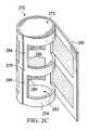
- FIG. 2Cillustrated an exploded perspective view of a multi-orientation filter according to an illustrative embodiment, the filter being cylindrically shaped;
- FIG. 2Dillustrated an exploded perspective view of a multi-orientation filter according to an illustrative embodiment, the filter being rectangular cubically shaped;
- FIG. 3illustrates a cross-sectional view of the liquid-collection canister of FIG. 1 taken at 3 - 3 ;
- FIG. 4illustrates a cross-sectional view of the liquid-collection canister of FIG. 1 similar to the cross-section of FIG. 3 but with a side wall of the canister oriented downward;
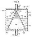
- FIG. 5illustrates a cross-sectional view of the liquid-collection canister of FIG. 1 similar to the cross-section of FIG. 3 but with an outlet wall of the canister oriented downward;
- FIG. 6illustrates a cross-sectional view of the liquid-collection canister of FIG. 1 similar to the cross-section of FIG. 3 but with an inlet wall of the canister oriented downward;
- FIG. 7illustrates a perspective view of the multi-orientation filter of FIG. 1 positioned in liquid-collection canister according to an illustrative embodiment
- FIG. 8illustrates a perspective view of the multi-orientation filter of FIG. 1 positioned in a liquid-collection canister according to an illustrative embodiment
- FIG. 9illustrates a perspective view of a liquid collection canister according to an illustrative embodiment, the canister having a multi-orientation filter.
- FIG. 10illustrates a cross-sectional view of the liquid-collection canister of FIG. 9 taken at 10 - 10 .
- reduced pressuregenerally refers to a pressure less than the ambient pressure at a tissue site that is being subjected to treatment. In most cases, this reduced pressure will be less than the atmospheric pressure at which the patient is located. Alternatively, the reduced pressure may be less than a hydrostatic pressure associated with tissue at the tissue site. Although the terms “vacuum” and “negative pressure” may be used to describe the pressure applied to the tissue site, the actual pressure reduction applied to the tissue site may be significantly less than the pressure reduction normally associated with a complete vacuum. Reduced pressure may initially generate fluid flow in the area of the tissue site. As the hydrostatic pressure around the tissue site approaches the desired reduced pressure, the flow may subside, and the reduced pressure is then maintained. Unless otherwise indicated, values of pressure stated herein are gauge pressures. Similarly, references to increases in reduced pressure typically refer to a decrease in absolute pressure, while decreases in reduced pressure typically refer to an increase in absolute pressure.
- tissue siterefers to a wound or defect located on or within any tissue, including but not limited to, bone tissue, adipose tissue, muscle tissue, neural tissue, dermal tissue, vascular tissue, connective tissue, cartilage, tendons, or ligaments.
- tissue sitemay further refer to areas of any tissue that are not necessarily wounded or defective, but are instead areas in which it is desired to add or promote the growth of additional tissue. For example, reduced pressure tissue treatment may be used in certain tissue areas to grow additional tissue that may be harvested and transplanted to another tissue location.
- a reduced pressure treatment system 100 for applying a reduced pressure to a tissue site 101 of a patientincludes a canister 102 having a filter 104 contained within the canister 102 .
- the canister 102is positioned in fluid communication with a reduced pressure source 108 and a reduced pressure dressing 112 that is positioned at the tissue site 101 .
- the reduced pressure dressing 112is fluidly connected to an inlet 116 of the canister 102 by a conduit 120 .
- the conduit 120may fluidly communicate with the reduced pressure dressing 112 through a tubing adapter 124 .
- a second conduit 128fluidly connects an outlet 132 of the canister 102 with the reduced pressure source 108 .
- the reduced pressure source 108is an electrically-driven vacuum pump.
- the reduced pressure source 108may instead be a manually-actuated or manually-charged pump that does not require electrical power.
- the reduced pressure source 108instead may be any other type of reduced pressure pump, or alternatively a wall suction port such as those available in hospitals and other medical facilities.
- the reduced pressure source 108may be housed within or used in conjunction with a reduced pressure treatment unit 140 , which may also contain sensors, processing units, alarm indicators, memory, databases, software, display units, and user interfaces that further facilitate the application of reduced pressure treatment to the tissue site 101 .
- a sensor or switchmay be disposed at or near the reduced pressure source 108 to determine a source pressure generated by the reduced pressure source 108 .
- the sensormay communicate with a processing unit that monitors and controls the reduced pressure that is delivered by the reduced pressure source 108 .
- the reduced pressure dressing 112includes a distribution manifold 144 adapted to be positioned at the tissue site 101 , and a cover 148 , or drape, that is positioned over the distribution manifold 144 to maintain reduced pressure beneath the cover 148 at the tissue site 101 .
- the cover 148may extend beyond a perimeter of the tissue site 101 and may include an adhesive or bonding agent on the cover 148 to secure the cover to tissue adjacent the tissue site 101 .
- the adhesive disposed on cover 148may be used to seal between the tissue and the cover 148 to prevent leakage of reduced pressure from the tissue site 101 .
- a seal layersuch as, for example, a hydrogel or other material may be disposed between the cover 148 and the tissue to augment or substitute for the sealing properties of the adhesive.
- the distribution manifold 144 of the reduced pressure dressing 112is adapted to contact the tissue site 101 .
- the distribution manifold 144may be partially or fully in contact with the tissue site 101 being treated by the reduced pressure dressing 112 .
- the distribution manifold 144may partially or fully fill the wound.
- the distribution manifold 144may be any size, shape, or thickness depending on a variety of factors, such as the type of treatment being implemented or the nature and size of the tissue site 101 .
- the size and shape of the distribution manifold 144may be customized by a user to cover a particular portion of the tissue site 101 , or to fill or partially fill the tissue site 101 .
- the distribution manifold 144may have, for example, a square shape, or may be shaped as a circle, oval, polygon, an irregular shape, or any other shape.
- the distribution manifold 144is a foam material that distributes reduced pressure to the tissue site 101 when the distribution manifold 144 is in contact with or near the tissue site 101 .
- the foam materialmay be either hydrophobic or hydrophilic.
- the distribution manifold 144is an open-cell, reticulated polyurethane foam such as GranuFoam® dressing available from Kinetic Concepts, Inc. of San Antonio, Tex.
- the distribution manifold 144also functions to wick fluid away from the tissue site 101 , while continuing to provide reduced pressure to the tissue site 101 as a manifold.
- the wicking properties of the distribution manifold 144draw fluid away from the tissue site 101 by capillary flow or other wicking mechanisms.
- An example of a hydrophilic foamis a polyvinyl alcohol, open-cell foam such as V.A.C. WhiteFoam® dressing available from Kinetic Concepts, Inc. of San Antonio, Tex.
- Other hydrophilic foamsmay include those made from polyether.
- Other foams that may exhibit hydrophilic characteristicsinclude hydrophobic foams that have been treated or coated to provide hydrophilicity.
- the distribution manifold 144may further promote granulation at the tissue site 101 when a reduced pressure is applied through the reduced pressure dressing 112 .
- any or all of the surfaces of the distribution manifold 144may have an uneven, coarse, or jagged profile that causes microstrains and stresses at the tissue site 101 when reduced pressure is applied through the distribution manifold 144 . These microstrains and stresses have been shown to increase new tissue growth.
- the distribution manifold 144may be constructed from bioresorbable materials that do not have to be removed from a patient's body following use of the reduced pressure dressing 112 .
- Suitable bioresorbable materialsmay include, without limitation, a polymeric blend of polylactic acid (PLA) and polyglycolic acid (PGA).
- the polymeric blendmay also include without limitation polycarbonates, polyfumarates, and capralactones.
- the distribution manifold 144may further serve as a scaffold for new cell-growth, or a scaffold material may be used in conjunction with the distribution manifold 144 to promote cell-growth.
- a scaffoldis a substance or structure used to enhance or promote the growth of cells or formation of tissue, such as a three-dimensional porous structure that provides a template for cell growth.
- Illustrative examples of scaffold materialsinclude calcium phosphate, collagen, PLA/PGA, coral hydroxy apatites, carbonates, or processed allograft materials.
- the filter 104includes a frame 202 that is pyramid-shaped and includes a base 206 , an apex 210 , and four walls 214 extending between the base 206 and the apex 210 .
- the base 206may include a flange 218 to allow the filter 104 to be easily mounted within the canister 102 to a wall of the canister 102 .
- a passage 222may be positioned in the base 206 to provide fluid communication with the outlet 132 of the canister 102 .
- the frame 202includes openings 226 in at least two of the four walls 214 . In the embodiment illustrated in FIG.
- the openings 226are disposed in only two of the four walls 214 , and the openings 226 are positioned in opposing walls. In another embodiment, the openings 226 may be disposed in two adjacent walls 214 , or alternatively in three or even four of the four walls 214 . It should also be noted that, while the frame 202 illustrated in FIG. 2A is pyramid-shaped with four walls, the frame 202 may be provided in a similar tapered configuration (i.e. tapering from a base to an apex) and instead include only three walls. In another embodiment, the frame 202 may include five walls or an even greater number of walls, with openings 226 in two or more of the walls.
- multiple openings 226may be disposed in each wall 214 that includes openings, thereby forming ribs 232 between the openings 226 .
- the openings 226may be of any shape or size including, without limitation, circular, square, rectangular, ovular, polygonal, irregular, or any other shape.
- the filter 104further includes filter elements 240 to cover the openings 226 in the walls 214 that include openings 226 .
- the filter element 240 covering each wall 214is substantially planar, although in alternative embodiments, non-planar filter elements may by used depending on the shape of the filter frame.
- the ribs 232provide structural support to prevent the filter elements 240 from being drawn through the openings 226 when the filter 104 is exposed to a reduced pressure.
- a baffle, or diverter 234may be positioned at the apex 210 of the filter 104 to assist in diverting liquid entering the canister 102 from spraying on the filter elements 240 .
- the filter 104 of FIG. 2Ais illustrated as having two filter elements 240 , one for each wall 214 of the frame 202 that includes openings 226 .
- multiple filter elements 240may be provided for each wall 214 .
- one filter element 240may be provided for each opening 226 .
- the filter elements 240may be adhesively attached, or attached or bonded by any other means to the walls 214 .
- the filter elements 240are preferably liquid-air separators that permit the transmission of gases, but substantially prevent the transmission of liquids through the filter elements 240 .
- the filter elements 240are hydrophobic membranes.
- the filter element 240may alternatively be any material coated with a hydrophobic material to make the filter element impermeable to liquid.
- the filter element 240may be a chemically bonded fluorocarbon monomer using a plasma process, thus increasing the hydrophobicity of the filter further.
- the filter element 240may be made from or coated with a lipophobic material.
- Some exemplary filter media materialsinclude foam, spun fiberglass, cotton gauze, polyester, glass fibers, polypropylene, microfibers, porous polymeric membranes, PTFE, and the like.
- the frame 202 and the filter elements 240define an interior region, or filter chamber 244 of the filter 104 .
- the interior region 244 of the filter 104is a space or chamber that is protected from liquid that collects within the canister.
- the frame 202 of the filter 104may be made from any type of material having a sufficient structural rigidity to provide mechanical support for the filter elements 240 .
- Some exemplary materialsinclude plastics, thermoplastics, thermosets, fiber-type materials, metals, metal alloys, and the like.
- the frame 202may be molded, cast, welded or otherwise formed to provide the desired shape.
- the flange 218 of the frame 202preferably is made of a material that is capable of being affixed, joined, welded, or otherwise attached to a wall of the canister 102 .
- a filter 250is provided that is similar in function and operation to, but different in shape than, filter 104 .
- the filter 250includes a frame 252 that is conically-shaped and includes a base 254 and an apex 256 .
- a conical wall 258extends from the base 254 to the apex 256 and includes at least one, and preferably a plurality, of openings 260 passing through the conical wall 258 .
- a passage 262may be positioned in the base 254 to provide fluid communication with the outlet 132 of the canister 102 .
- the multiple openings 260 of filter 250form ribs 264 between the openings 260 .
- the openings 260may be of any shape or size including, without limitation, circular, square, rectangular, ovular, polygonal, irregular, or any other shape.
- the filter 250further includes one or more filter elements 266 to cover the openings 260 in the conical wall 258 .
- one filter element 266is illustrated and since the filter element 266 wraps around the conical wall 258 , the filter element 266 includes non-planar portions when installed on the frame 252 .
- the ribs 264provide structural support to prevent the filter element 266 from being drawn through the openings 260 when the filter 250 is exposed to a reduced pressure.
- the number of filter elements 266 , the means of attaching the filter elements 266 to the frame 252 , the function of the filter elements 266 , and the material composition of the filter elements 266is similar to that described for the filter elements 240 of filter 104 .
- the frame 252 and the filter elements 266define an interior region, or chamber 268 of the filter 250 similar to interior region 244 of filter 104 .
- a filter 270is provided that is similar in function and operation to, but different in shape than, filters 104 and 250 .
- the filter 270includes a frame 272 that is cylindrically-shaped and includes a cylindrical wall 278 that has at least one and preferably a plurality of openings 280 passing through the cylindrical wall 278 .
- a passage(not shown) may be positioned in a base 274 of the frame 272 to provide fluid communication with the outlet 132 of the canister 102 .
- the multiple openings 280 of filter 270form ribs 284 between the openings 280 .
- the openings 280may be of any shape or size including, without limitation, circular, square, rectangular, ovular, polygonal, irregular, or any other shape.
- the filter 270further includes one or more filter elements 285 to cover the openings 280 in the cylindrical wall 278 .
- one filter element 285is illustrated and since the filter element 285 wraps around the cylindrical wall 278 , the filter element 285 includes non-planar portions when installed on the frame 272 .
- the ribs 284provide structural support to prevent the filter element 285 from being drawn through the openings 280 when the filter 270 is exposed to a reduced pressure.
- the number of filter elements 285 , the means of attaching the filter elements 285 to the frame 252 , the function of the filter elements 285 , and the material composition of the filter elements 285is similar to that described for the filter elements 240 of filter 104 .
- the frame 272 and the filter elements 285define an interior region, or chamber 283 of the filter 270 similar to interior region 244 of filter 104 .
- a filter 286is provided that is similar in function and operation to, but different in shape than, filters 104 , 250 , 270 .
- the filter 286includes a frame 288 that is cubically or rectangular cubically-shaped and includes a rectangular-cubical wall 290 that has at least one and preferably a plurality of openings 292 passing through the wall 290 .
- a passage 293may be positioned in a base 294 of the frame 288 to provide fluid communication with the outlet 132 of the canister 102 .
- the multiple openings 292 of filter 286form ribs 296 between the openings 292 .
- the openings 292may be of any shape or size including, without limitation, circular, square, rectangular, ovular, polygonal, irregular, or any other shape.
- the filter 286further includes one or more filter elements 298 to cover the openings 292 in the wall 290 .
- one filter element 298is illustrated on each of the walls 290 , and each filter element 298 is substantially planar when installed on the frame 288 .
- the ribs 296provide structural support to prevent the filter element 298 from being drawn through the openings 292 when the filter 286 is exposed to a reduced pressure.
- the number of filter elements 298 , the means of attaching the filter elements 298 to the frame 252 , the function of the filter elements 298 , and the material composition of the filter elements 298is similar to that described for the filter elements 240 of filter 104 .
- the frame 288 and the filter elements 298define an interior region, or chamber 299 of the filter 286 similar to interior region 244 of filter 104 .
- canister 102is substantially cubical or rectangular cubical in shape.
- Canister 102includes six walls: a first wall 302 in which the outlet 132 of the canister 102 is disposed, a second wall 304 in which the inlet 116 of the canister 102 is disposed, a third wall 306 which represents the bottom wall of the canister 102 in FIG. 1 , a fourth wall 308 which represents the top wall of the canister 102 in FIG. 1 , a fifth wall 310 , and a sixth wall 312 . Together, the six walls define an interior chamber, or interior space 318 of the canister 102 .
- the filter 104is positioned within the interior space 318 of the canister 102 such that the base 206 of the filter 104 is adjacent the first wall 302 .
- the passage 222 in the base 206 of the filter 104is aligned with the outlet 132 of the canister 102 such that reduced pressure from the reduced pressure source 108 may be communicated to the interior region 244 of the filter 104 .
- the base 206 of the filter 104is preferably connected to and supported by the first wall 302 in any number of ways including, without limitation, welding, gluing or other fastening means.
- a sealing connectionis provided between the outlet 132 and/or conduit 128 and the interior region 244 .
- This sealing connectionprevents direct fluid communication between the interior space 318 of the canister 102 and the conduit 128 . Instead, any fluid communication between the interior space 318 of the canister 102 and the conduit 128 must occur via the interior region 244 of the filter 104 . Due to the presence of the liquid-blocking filter elements 240 , only gases from the interior space 318 of the canister 102 may pass through the interior region 244 to the conduit 128 .
- the positioning of the inlet 116 and outlet 132 of the canister 102may vary, in the embodiment illustrated in FIG. 1 , the inlet 116 and outlet 132 are disposed in opposing walls of the canister 102 .
- the inlet 116 of the canister 102is generally centered in the second wall 304
- the outlet 132is generally centered in the first wall 302 .
- the placement of the filter 104is such that the base 206 completely covers the first wall 302 , and the apex 210 of the filter 104 is centrally positioned adjacent the inlet 116 .
- filters of other shapesmay be similarly positioned within a canister similar to canister 102 .
- a conically-shaped filtersuch as filter 250 could be positioned in the canister 102 such that the apex 256 of filter 250 is centrally aligned with the inlet 116 .
- Filter 270 and filter 286may similarly be positioned in the canister 102 as an alternative to filter 104 .
- the interior space 318 of the canisterforms a first space where liquid from the tissue site 101 is collected.
- the interior region 244 of the filter 104forms a second space, which is a dry space that is substantially protected from liquid.
- the interior region 244allows the passage of reduced pressure between the reduced pressure source 108 and the interior space 318 of the canister 102 .
- the reduced pressureis delivered to the tissue site 101 , which results in liquid 332 at the tissue site 101 being drawn into the interior space 318 of the canister 102 .
- FIG. 3which represents an orientation of the canister with the third wall 306 down (similar to that illustrated in FIG.
- the liquid 332begins to fill the interior space 318 of the canister 102 but is substantially prevented from passing through the filter elements 240 to enter the interior region 244 of the filter 104 .
- the liquid 332includes a surface 334 that is substantially planar and forms a liquid plane 335 .
- any portion of the filter elements 240 below the surface 334 of the liquid 332will no longer allow transmission or flow of gas between the interior space 318 and the interior region 244 . In other words, the reduced pressure will no longer be delivered or transferred to the interior space 318 through the portion of the filter element 240 that is covered in liquid 332 .
- a dry region 336 of the filter element 240 located above the liquid surface 334continues to allow flow of gas or transmission of reduced pressure between the interior space 318 and the interior region 244 . As long as a portion of the filter element 240 remains uncovered by liquid 332 , the filter element will continue to permit gas flow and transmission of reduced pressure.
- the filter 104is illustrated in an orientation in which fifth wall 310 is positioned in a downward position.
- the filter 104is illustrated in an orientation in which first wall 302 is positioned in a downward position.
- the filter 104is illustrated in an orientation in which second wall 304 is positioned in a downward position.
- the presence of liquid within the interior space 318 of the canister 102blocks transmission of gas through the portions of the filter elements 240 beneath the surface 334 of the liquid.
- gas flow and thus reduced pressure transmission between the reduced pressure source 108 and the tissue site 101continues due to the presence of the dry region 336 of the filter elements 240 above the surface 334 of the liquid 332 .
- the success of the filter 104 at allowing large-volume liquid collection in any orientation of the canister 102is due in part to the large and multi-faceted filter elements 240 that are a part of the filter 104 .
- the tapered nature of the filter 104increases the liquid-collecting volume of the interior space 318 , but also provides a large surface area for the filter elements 240 .
- the filter elements 240 of filter 104are substantially planar, but the plane associated with each filter element 240 is obliquely angled relative to the planes of other filter elements 240 . This angled relationship between the filter elements 240 results in at least a portion of one of the filter elements 240 being not parallel to the liquid plane 335 of the liquid 332 in any particular orientation of the canister 102 . Since there is almost always a filter element 240 that will not be parallel to the surface 334 of the liquid 332 , the ability of the filter elements 240 to continue gas transmission during higher volumes of liquid collection is improved.
- the baffle 234may be positioned on the filter 104 or canister 102 to further prevent the liquid 332 from contacting the filter elements 240 as the fluid enters the inlet 116 of the canister 102 and flows downward with gravity to the bottom of the canister 102 . Since even incidental contact with liquid or bubbles formed by liquid entering the canister may result in protein deposition on the filter elements 240 , and thus premature blockage of gas transmission by the filter elements 240 , the baffle 234 may serve a valuable role in preventing premature contact between the liquid 332 and the filter elements 240 .
- the base 206instead may be positioned against a wall of the canister 102 that does not include the outlet.
- the filter 104may be positioned with base 206 adjacent the third wall 306 , the fourth wall 308 , the fifth wall 310 , or the sixth wall 312 .
- the outlet 132may be fluidly connected to the interior region 244 of the filter 104 by a conduit that is plumbed through the base 206 , the apex 210 , or one of the walls 214 of the filter 104 .
- outlet 132 and inlet 116 of the canister 102have been described as being located in opposing walls of the canister 102 , the outlet 132 and inlet 116 may be positioned in adjacent walls, or even in the same wall depending on the size, shape, and positioning of the filter 104 .
- the filter 104may be positioned such that base 206 does not lie flat against a wall of the canister. Instead, the filter 104 is positioned such that the base 206 is adjacent a corner 706 formed between two walls of the canister 102 . The outlet 132 is positioned within the corner 706 , and a conduit 710 provides communication between the outlet 132 and the passage 222 of the base 206 .
- filters of other shapessuch as those described herein may also be positioned as illustrated in FIG. 7 .
- a filter 804 similar in shape to filter 104may be positioned in a cylindrically-shaped canister 802 .
- the filter 804includes a base 806 , an apex 810 , a plurality of walls 814 , and a plurality of filter elements 840 .
- the base 806is positioned adjacent a cylindrical wall 818 of the canister 802 , although in another embodiment, the base 806 could be positioned against one of two end walls 820 of the canister 802 .
- the canister 802 and filter 804are similar in function to the canister 102 and filter 104 , and the filter 804 is similarly capable of allowing continued transmission of reduced pressure and collection of liquid in multiple orientations of the canister 802 .
- a canister 902may be used with a reduced pressure treatment system similar to reduced pressure treatment system 100 .
- Canister 902includes a basin 904 and a lid 906 that are capable of complementary engagement to form a substantially sealed interior chamber, or interior space 910 within the canister.
- the canister 902includes an inlet 914 that may be fluidly connected to a reduced pressure dressing and an outlet 918 that may be fluidly connected to a reduced pressure source.
- the lid 906forms a substantially planar wall 922 of the canister 902 .
- a filter 926is positioned on the wall 922 and includes a first chamber 932 and a second chamber 936 , both of which extend from the wall 922 .
- the first chamber 932includes an opening 938 disposed at an end of the first chamber 932 opposite the wall 922
- the second chamber 936includes an opening 940 disposed at an end of the second chamber 936 opposite the wall 922 .
- the opening 938 of the first chamber 932allows fluid communication between the interior space 910 and the first chamber 932
- the opening 940 of the second chamber 936allows fluid communication between the interior space 910 and the second chamber 936 .
- the volume of the first chamber 932is greater than the volume of the second chamber 936 due in large part to the variation in distance that each chamber extends from the wall 922 .
- the distance between the opening 938 of the first chamber 932 and the wall 922is greater than the distance between the opening 940 of the second chamber 936 and the wall 922 .
- Each of the openings 938 , 940are covered with a filter element similar in function and material composition to the filter elements described herein.
- a first filter element 950is positioned over the opening of the first chamber 932
- a second filter element 954is positioned over the opening of the second chamber 936 .
- Both the first and second filter elements 950 , 954may be substantially planar, and the variation in distance between each filter element and the wall relative to one another places the filter elements 950 , 954 in separate planes.
- the plane associated with filter element 950is substantially parallel to the plane associated with filter element 954 , and both planes are substantially parallel to the wall 922 .
- the filter elementsmay be oriented such that the planes associated with the filter elements are not parallel.
- both the first chamber 932 and the second chamber 936are fluidly connected to the outlet 918 of the canister 902 .
- a first channel 960is positioned along the wall 922 and is fluidly connected between the first chamber 932 and the outlet 918 .
- a second channel 964is positioned along the wall 922 and is fluidly connected between the second chamber 936 and the outlet 918 .
- An odor filter 968such as for example a charcoal filter, may be positioned at a junction of the first channel 960 and the second channel 964 to reduce odor associated with gases withdrawn from the canister 902 .
- the interior space 910 of the canister 902forms a first space where liquid from a tissue site may be collected.
- the first chamber 932 and the second chamber 936form a second space, which is a dry space that is substantially protected from liquid.
- the first and second chambers 932 , 936allow the passage of reduced pressure between a reduced pressure source and the interior space 910 of the canister 902 .
- a reduced pressureis applied by the reduced pressure source to the canister 902 , the reduced pressure is delivered to the tissue site, which results in liquid at the tissue site being drawn into the interior space 910 of the canister 902 . Similar in operation to the canister 102 illustrated in FIGS.
- the liquidbegins to fill the interior space 910 of the canister 902 but is substantially prevented from passing through the filter elements 950 , 954 to enter the first and second chambers 932 , 936 of the filter 926 .
- the sizing, positioning, and arrangement of the first and second filter elements 950 , 954is such that substantial amounts of liquid collection are permitted in any particular orientation of the canister 902 .
- filter 926allows the canister to continue to transmit reduced pressure even as the level of liquid within the canister rises to and beyond the volume of the interior space 910 being half full of liquid. This particular feature of the filter 926 is possible due to the multi-planar positioning of the filter elements 950 , 954 relative to one another, and due to the spaced positioning of the filter elements 950 , 954 .
- the canisters 102 , 802 and 902may be any type of material of sufficient rigidity and structural integrity to withstand the reduced pressure required for reduced pressure treatment and to contain liquid therein.
- Some exemplary materials of the canistersare plastics, polymers, thermoplastics, metals, metal alloys, composition material, fiber-type materials, and the like.
- the canistersmay have a plurality of individual sides that are affixed, joined, and/or welded together to create the desired shape, e.g., rectangular or cylindrical, or may be a molded single or multi-part housing.
- the plastics described hereinmay be a substance or structure capable of being shaped or molded with or without the application of heat, a high polymer, usually synthetic, combined with other ingredients such as curatives, fillers, reinforcing agents, plasticizers, etc.
- Plasticscan be formed or molded under heat and pressure in its raw state and machined to high dimensional accuracy, trimmed and finished in its hardened state.
- the thermoplastic typecan be resoftened to its original condition by heat.
- the plasticsmay mean engineered plastics such as those that are capable of sustaining high levels of stress and are machinable and dimensionally stable.
- thermoplastics described hereinmay be high polymers that softens when exposed to heat and return to their original condition when cooled to room temperature. Generally, it may apply to synthetics such as polyvinylchloride, nylons, fluorocarbons, linear polyethylene, polyurethane prepolymer, polystyrene, polypropylene, and cellulosic and acrylic resins, for example.
- Each of the filters described hereinmay be varied in size or shape to better accommodate a canister of a particular size or shape. While several canister shapes have been illustrated and described, use of the filters described herein, and the advantages that these filters provide, is not limited to any particular shape of canister.
- filter chambersWhile some of the filters presented herein have been described as having a single interior space or chamber, the number of filter chambers is not limited. Multiple filter chambers that are either independently or jointly connected to the canister outlet or multiple canister outlets may be employed, again depending at least partially upon the size and shape of the canister. Similarly, multiple filter elements may be used to increase the time that the filter maintains gas transmission during liquid collection activities.
- a method of collecting liquid from a tissue sitemay include applying a reduced pressure to a second space of a canister such as the liquid-collection canisters described with reference to FIGS. 1-10 .
- the second space of the liquid-collection canisterhas an opening to allow communication with a first space of the canister.
- the openingis covered by a non-planar filter element that allows gaseous communication through the non-planar filter element such that the reduced pressure is communicated to the first space of the canister. Liquid is drawn into the first space, and flow through the non-planar filter element is filtered to substantially prevent the liquid from entering the second space.
- a method of collecting liquid from a tissue siteincludes applying a reduced pressure to a second space of a canister.
- the second spacehas a plurality of openings to allow communication with a first space of the canister.
- the openingsare covered by a plurality of liquid-air separators, and at least two of the plurality of liquid-air separators are substantially planar and located within different planes. Gaseous communication is allowed through the liquid-air separators such that the reduced pressure is communicated to the first space of the canister.
- the liquidis drawn into the first space, and flow through the liquid-air separators is filtered to substantially prevent the liquid from entering the second space.
- a method of collecting liquid from a tissue siteincludes applying a reduced pressure to a first chamber and a second chamber of a canister.
- the first and second chamberseach extend from a wall of the canister and each include an opening at an end of the chamber opposite the wall.
- the opening of the first chamberis covered by a first filter element
- the opening of the second chamberis covered by a second filter element.
- a distance from the opening of the first chamber to the wallis greater than a distance from the opening of the second chamber to the wall.
- the methodfurther includes allowing gaseous communication through the first and second filter elements such that the reduced pressure is communicated to a first space of the canister.
- the liquidis drawn into the first space, and flow through the first and second filter elements is filtered to substantially prevent the liquid from entering the first and second chambers.
- the filters and liquid-collection canisters described hereinmay also be used as part of a process or method for administering reduced pressure treatment to a tissue site.
- the methodincludes applying a reduced pressure to a second space of a canister such as the canisters described herein.
- the second spacehas an opening to allow communication with a first space of the canister, and the opening is covered by a non-planar filter element. Gaseous communication is allowed through the non-planar filter element such that the reduced pressure is communicated to the first space of the canister.
- the reduced pressureis communicated to the tissue site.
- a liquidis drawn from the tissue site into the first space, and flow through the non-planar filter element is filtered to substantially prevent the liquid from entering the second space.
- a method of administering reduced pressure treatment to a tissue sitemay include applying a reduced pressure to a second space of a canister similar to the canisters described herein.
- the second spacehas a plurality of openings to allow communication with a first space of the canister.
- the openingsare covered by a plurality of liquid-air separators, and at least two of the plurality of liquid-air separators are substantially planar and located within different planes.
- the methodfurther includes allowing gaseous communication through the liquid-air separators such that the reduced pressure is communicated to the first space of the canister.
- the reduced pressureis communicated to the tissue site.
- a liquidis drawn from the tissue site into the first space, and flow through the liquid-air separators is filtered to substantially prevent the liquid from entering the second space.
- a method of administering reduced pressure treatment to a tissue siteincludes applying a reduced pressure to a first chamber and a second chamber of a canister such as the canisters described herein.
- the first and second chamberseach extend from a wall of the canister, and each include an opening at an end of the chamber opposite the wall.
- the opening of the first chamberis covered by a first filter element, and the opening of the second chamber is covered by a second filter element.
- a distance from the opening of the first chamber to the wallis greater than a distance from the opening of the second chamber to the wall.
- Gaseous communicationis allowed through the first and second filter elements such that the reduced pressure is communicated to a first space of the canister.
- the reduced pressureis communicated to the tissue site.
- a liquidis drawn from the tissue site into the first space, and flow through the first and second filter elements is filtered to substantially prevent the liquid from entering the first and second chambers.
Landscapes
- Health & Medical Sciences (AREA)
- Heart & Thoracic Surgery (AREA)
- Animal Behavior & Ethology (AREA)
- General Health & Medical Sciences (AREA)
- Anesthesiology (AREA)
- Biomedical Technology (AREA)
- Hematology (AREA)
- Life Sciences & Earth Sciences (AREA)
- Veterinary Medicine (AREA)
- Engineering & Computer Science (AREA)
- Public Health (AREA)
- Vascular Medicine (AREA)
- Chemical & Material Sciences (AREA)
- Chemical Kinetics & Catalysis (AREA)
- Otolaryngology (AREA)
- Media Introduction/Drainage Providing Device (AREA)
- External Artificial Organs (AREA)
Abstract
Description
Claims (19)
Priority Applications (4)
| Application Number | Priority Date | Filing Date | Title |
|---|---|---|---|
| US12/478,244US8172818B2 (en) | 2008-06-04 | 2009-06-04 | Reduced-pressure, liquid-collection canister with multi-orientation filter |
| US13/444,310US9211486B2 (en) | 2008-06-04 | 2012-04-11 | Reduced-pressure, liquid-collection canister with multi-orientation filter |
| US14/938,587US10149966B2 (en) | 2008-06-04 | 2015-11-11 | Reduced-pressure, liquid-collection canister with multi-orientation filter |
| US16/178,376US10994106B2 (en) | 2008-06-04 | 2018-11-01 | Reduced-pressure, liquid-collection canister with multi-orientation filter |
Applications Claiming Priority (2)
| Application Number | Priority Date | Filing Date | Title |
|---|---|---|---|
| US5883008P | 2008-06-04 | 2008-06-04 | |
| US12/478,244US8172818B2 (en) | 2008-06-04 | 2009-06-04 | Reduced-pressure, liquid-collection canister with multi-orientation filter |
Related Child Applications (1)
| Application Number | Title | Priority Date | Filing Date |
|---|---|---|---|
| US13/444,310ContinuationUS9211486B2 (en) | 2008-06-04 | 2012-04-11 | Reduced-pressure, liquid-collection canister with multi-orientation filter |
Publications (2)
| Publication Number | Publication Date |
|---|---|
| US20090306630A1 US20090306630A1 (en) | 2009-12-10 |
| US8172818B2true US8172818B2 (en) | 2012-05-08 |
Family
ID=41057457
Family Applications (1)
| Application Number | Title | Priority Date | Filing Date |
|---|---|---|---|
| US12/478,244Active2030-03-11US8172818B2 (en) | 2008-06-04 | 2009-06-04 | Reduced-pressure, liquid-collection canister with multi-orientation filter |
Country Status (12)
| Country | Link |
|---|---|
| US (1) | US8172818B2 (en) |
| EP (1) | EP2280744B1 (en) |
| JP (5) | JP2011524191A (en) |
| KR (1) | KR101259281B1 (en) |
| CN (2) | CN104383613B (en) |
| AU (1) | AU2009256128B2 (en) |
| BR (1) | BRPI0909904A2 (en) |
| CA (3) | CA2984749C (en) |
| MX (1) | MX2010013323A (en) |
| RU (1) | RU2471510C2 (en) |
| TW (1) | TW201000161A (en) |
| WO (1) | WO2009149250A1 (en) |
Cited By (13)
| Publication number | Priority date | Publication date | Assignee | Title |
|---|---|---|---|---|
| US20110054422A1 (en)* | 2009-08-27 | 2011-03-03 | Christopher Brian Locke | Re-epithelialization wound dressings and systems |
| US20110054420A1 (en)* | 2009-08-27 | 2011-03-03 | Christopher Brian Locke | Reduced-pressure wound dressings and systems for re-epithelialization and granulation |
| US20120046624A1 (en)* | 2010-08-18 | 2012-02-23 | Christopher Brian Locke | Reduced-pressure, multi-orientation, liquid-collection canister |
| US20130116639A1 (en)* | 2009-12-23 | 2013-05-09 | Kci Licensing, Inc. | Reduced-pressure, multi-orientation, liquid-collection canister |
| US20160058986A1 (en)* | 2008-06-04 | 2016-03-03 | Kci Licensing, Inc. | Reduced-pressure, liquid-collection canister with multi-orientation filter |
| US10085892B2 (en) | 2013-03-07 | 2018-10-02 | Life Sciences Llc | Apparatus and method for wound infection prevention |
| US10314955B2 (en) | 2015-10-21 | 2019-06-11 | Lifecell Corporation | Systems and methods for medical device control |
| US20210113745A1 (en)* | 2012-02-21 | 2021-04-22 | Kci Licensing, Inc. | Multi-Orientation Canister For Use With A Reduced Pressure Treatment System |
| US11091733B2 (en) | 2016-08-30 | 2021-08-17 | Lifecell Corporation | Systems and methods for medical device control |
| US20220016330A1 (en)* | 2008-08-08 | 2022-01-20 | Kci Licensing, Inc. | Reduced-pressure treatment systems with reservoir control |
| US11261418B2 (en) | 2012-09-06 | 2022-03-01 | The Gid Group, Inc. | Tissue processing apparatus and method for processing adipose tissue |
| US20220355020A1 (en)* | 2007-11-21 | 2022-11-10 | T.J.Smith And Nephew,Limited | Suction device and dressing |
| US12420222B2 (en) | 2021-09-06 | 2025-09-23 | Fresenius Hemocare Italia S.R.L. | Filter assembly and container for collecting a body fluid containing the same |
Families Citing this family (34)
| Publication number | Priority date | Publication date | Assignee | Title |
|---|---|---|---|---|
| GB0715259D0 (en) | 2007-08-06 | 2007-09-12 | Smith & Nephew | Canister status determination |
| US9408954B2 (en) | 2007-07-02 | 2016-08-09 | Smith & Nephew Plc | Systems and methods for controlling operation of negative pressure wound therapy apparatus |
| US12121648B2 (en) | 2007-08-06 | 2024-10-22 | Smith & Nephew Plc | Canister status determination |
| WO2011090996A2 (en)* | 2010-01-20 | 2011-07-28 | Kci Licensing, Inc. | Leak-resistant bandage systems and methods with hydrophilic foam wound insert for fluid-instillation and/or negative-pressure wound therapies |
| US8604265B2 (en) | 2010-04-16 | 2013-12-10 | Kci Licensing, Inc. | Dressings and methods for treating a tissue site on a patient |
| CN103796692B (en) | 2011-09-13 | 2016-06-22 | 凯希特许有限公司 | Pressure Relief Tanks with Hydrophobic Pores |
| HK1197964A2 (en) | 2011-12-03 | 2015-02-27 | DePuy Synthes Products, Inc. | Safe cutting heads and systems for fast removal of a target tissue |
| EP3081240B1 (en)* | 2012-02-21 | 2019-04-03 | KCI Licensing, Inc. | A multi-orientation canister for use with a reduced pressure treatment system |
| IN2014KN02620A (en)* | 2012-04-30 | 2015-05-08 | Univ Johns Hopkins | |
| WO2013173705A1 (en) | 2012-05-18 | 2013-11-21 | Basf Se | Encapsulated particle |
| KR20150013788A (en) | 2012-05-18 | 2015-02-05 | 바스프 에스이 | An encapsulated particle |
| BR112015002600A2 (en) | 2012-08-08 | 2017-07-04 | Smith & Nephew | custom-made wound care device and methods for use in negative pressure wound therapy |
| CN104619360B (en)* | 2012-09-12 | 2019-08-16 | 凯希特许有限公司 | System and method for collecting exudate in decompression therapy |
| JP6289475B2 (en)* | 2012-10-01 | 2018-03-07 | メンリッケ・ヘルス・ケア・アーベー | Wound therapy device |
| US9944568B2 (en) | 2012-11-16 | 2018-04-17 | Basf Se | Encapsulated fertilizer particle containing pesticide |
| US10092682B2 (en)* | 2013-03-13 | 2018-10-09 | Kci Licensing, Inc. | Expandable fluid collection canister |
| KR101459461B1 (en) | 2013-05-20 | 2014-11-10 | 현대자동차 주식회사 | Touch screen input system having analog operation device |
| AU2014290685B2 (en)* | 2013-07-18 | 2018-12-13 | Kci Licensing, Inc. | Fluid volume measurement using canister resonance for reduced pressure therapy systems |
| EP3021768B1 (en) | 2013-07-19 | 2020-08-19 | DePuy Synthes Products, Inc. | An anti-clogging device for a vacuum-assisted, tissue removal system |
| EP3096725B1 (en) | 2014-01-21 | 2023-10-18 | Smith & Nephew plc | Wound treatment apparatuses |
| DE102014214045A1 (en) | 2014-07-18 | 2016-01-21 | Asskea Gmbh | Apparatus for aspirating body fluid and filter module therefor |
| US20160287482A1 (en)* | 2015-04-05 | 2016-10-06 | Sarah Bassett | Methods and Apparatuses for Orogastric Decompression |
| EP3291738B1 (en) | 2015-05-07 | 2024-02-14 | Avitus Orthopaedics, Inc. | Systems for bone and tissue harvesting |
| CN104984418A (en)* | 2015-06-30 | 2015-10-21 | 昆山韦睿医疗科技有限公司 | Negative-pressure therapy system and exudate collecting box thereof |
| ES2775597T3 (en) | 2015-10-21 | 2020-07-27 | Lifecell Corp | Systems and methods for tube management |
| EP3595737B1 (en)* | 2017-03-17 | 2023-04-05 | Stryker Corporation | Manifold for a medical/surgical waste collection system with a material collection volume for collecting material entrained within fluid |
| WO2019027703A1 (en)* | 2017-07-31 | 2019-02-07 | Kcl Licensing, Inc. | Liquid collection container for negative-pressure therapy |
| CN111836655A (en)* | 2017-11-16 | 2020-10-27 | 康沃特克有限公司 | fluid collection equipment |
| CN109731153B (en)* | 2019-01-24 | 2021-06-08 | 山东农业大学 | A transport device that can quickly extract oocytes and preserve them |
| JP2021186744A (en)* | 2020-05-29 | 2021-12-13 | 極東開発工業株式会社 | Fermentation apparatus, liquid fertilizer manufacturing apparatus, and liquid fertilizer manufacturing method |
| EP4308185A1 (en)* | 2021-03-17 | 2024-01-24 | KCI Manufacturing Unlimited Company | Evaporative fluid management canister for wound therapy system |
| CN113842511B (en)* | 2021-09-27 | 2024-08-30 | 南京市中西医结合医院 | Medical effusion cleaning device |
| EP4426367A1 (en)* | 2021-11-05 | 2024-09-11 | KCI Manufacturing Unlimited Company | Liquid-collection canister with multi-orientation filter |
| CN119950827A (en)* | 2024-12-26 | 2025-05-09 | 萨科(厦门)医疗科技有限公司 | A negative pressure drainage bottle |
Citations (120)
| Publication number | Priority date | Publication date | Assignee | Title |
|---|---|---|---|---|
| US1355846A (en) | 1920-02-06 | 1920-10-19 | David A Rannells | Medical appliance |
| US2547758A (en) | 1949-01-05 | 1951-04-03 | Wilmer B Keeling | Instrument for treating the male urethra |
| US2632443A (en) | 1949-04-18 | 1953-03-24 | Eleanor P Lesher | Surgical dressing |
| GB692578A (en) | 1949-09-13 | 1953-06-10 | Minnesota Mining & Mfg | Improvements in or relating to drape sheets for surgical use |
| US2682873A (en) | 1952-07-30 | 1954-07-06 | Johnson & Johnson | General purpose protective dressing |
| US2910763A (en) | 1955-08-17 | 1959-11-03 | Du Pont | Felt-like products |
| US2969057A (en) | 1957-11-04 | 1961-01-24 | Brady Co W H | Nematodic swab |
| US3066672A (en) | 1960-09-27 | 1962-12-04 | Jr William H Crosby | Method and apparatus for serial sampling of intestinal juice |
| US3367332A (en) | 1965-08-27 | 1968-02-06 | Gen Electric | Product and process for establishing a sterile area of skin |
| US3520300A (en) | 1967-03-15 | 1970-07-14 | Amp Inc | Surgical sponge and suction device |
| US3568675A (en) | 1968-08-30 | 1971-03-09 | Clyde B Harvey | Fistula and penetrating wound dressing |
| US3648692A (en) | 1970-12-07 | 1972-03-14 | Parke Davis & Co | Medical-surgical dressing for burns and the like |
| US3682180A (en) | 1970-06-08 | 1972-08-08 | Coilform Co Inc | Drain clip for surgical drain |
| US3826254A (en) | 1973-02-26 | 1974-07-30 | Verco Ind | Needle or catheter retaining appliance |
| DE2640413A1 (en) | 1976-09-08 | 1978-03-09 | Wolf Gmbh Richard | CATHETER MONITORING DEVICE |
| US4080970A (en) | 1976-11-17 | 1978-03-28 | Miller Thomas J | Post-operative combination dressing and internal drain tube with external shield and tube connector |
| US4096853A (en) | 1975-06-21 | 1978-06-27 | Hoechst Aktiengesellschaft | Device for the introduction of contrast medium into an anus praeter |
| US4139004A (en) | 1977-02-17 | 1979-02-13 | Gonzalez Jr Harry | Bandage apparatus for treating burns |
| US4165748A (en) | 1977-11-07 | 1979-08-28 | Johnson Melissa C | Catheter tube holder |
| US4184510A (en) | 1977-03-15 | 1980-01-22 | Fibra-Sonics, Inc. | Valued device for controlling vacuum in surgery |
| US4233969A (en) | 1976-11-11 | 1980-11-18 | Lock Peter M | Wound dressing materials |
| US4245630A (en) | 1976-10-08 | 1981-01-20 | T. J. Smith & Nephew, Ltd. | Tearable composite strip of materials |
| US4256109A (en) | 1978-07-10 | 1981-03-17 | Nichols Robert L | Shut off valve for medical suction apparatus |
| US4261363A (en) | 1979-11-09 | 1981-04-14 | C. R. Bard, Inc. | Retention clips for body fluid drains |
| US4275721A (en) | 1978-11-28 | 1981-06-30 | Landstingens Inkopscentral Lic, Ekonomisk Forening | Vein catheter bandage |
| US4284079A (en) | 1979-06-28 | 1981-08-18 | Adair Edwin Lloyd | Method for applying a male incontinence device |
| US4297995A (en) | 1980-06-03 | 1981-11-03 | Key Pharmaceuticals, Inc. | Bandage containing attachment post |
| US4333468A (en) | 1980-08-18 | 1982-06-08 | Geist Robert W | Mesentery tube holder apparatus |
| US4373519A (en) | 1981-06-26 | 1983-02-15 | Minnesota Mining And Manufacturing Company | Composite wound dressing |
| US4382441A (en) | 1978-12-06 | 1983-05-10 | Svedman Paul | Device for treating tissues, for example skin |
| US4392858A (en) | 1981-07-16 | 1983-07-12 | Sherwood Medical Company | Wound drainage device |
| US4392853A (en) | 1981-03-16 | 1983-07-12 | Rudolph Muto | Sterile assembly for protecting and fastening an indwelling device |
| US4419097A (en) | 1981-07-31 | 1983-12-06 | Rexar Industries, Inc. | Attachment for catheter tube |
| EP0100148A1 (en) | 1982-07-06 | 1984-02-08 | Dow Corning Limited | Medical-surgical dressing and a process for the production thereof |
| US4465485A (en) | 1981-03-06 | 1984-08-14 | Becton, Dickinson And Company | Suction canister with unitary shut-off valve and filter features |
| EP0117632A2 (en) | 1983-01-27 | 1984-09-05 | Johnson & Johnson Products Inc. | Adhesive film dressing |
| US4475909A (en) | 1982-05-06 | 1984-10-09 | Eisenberg Melvin I | Male urinary device and method for applying the device |
| US4480638A (en) | 1980-03-11 | 1984-11-06 | Eduard Schmid | Cushion for holding an element of grafted skin |
| US4525166A (en) | 1981-11-21 | 1985-06-25 | Intermedicat Gmbh | Rolled flexible medical suction drainage device |
| US4525374A (en) | 1984-02-27 | 1985-06-25 | Manresa, Inc. | Treating hydrophobic filters to render them hydrophilic |
| US4540412A (en) | 1983-07-14 | 1985-09-10 | The Kendall Company | Device for moist heat therapy |
| US4543100A (en) | 1983-11-01 | 1985-09-24 | Brodsky Stuart A | Catheter and drain tube retainer |
| US4548202A (en) | 1983-06-20 | 1985-10-22 | Ethicon, Inc. | Mesh tissue fasteners |
| US4551139A (en) | 1982-02-08 | 1985-11-05 | Marion Laboratories, Inc. | Method and apparatus for burn wound treatment |
| EP0161865A2 (en) | 1984-05-03 | 1985-11-21 | Smith and Nephew Associated Companies p.l.c. | Adhesive wound dressing |
| US4569348A (en) | 1980-02-22 | 1986-02-11 | Velcro Usa Inc. | Catheter tube holder strap |
| US4605399A (en) | 1984-12-04 | 1986-08-12 | Complex, Inc. | Transdermal infusion device |
| US4608041A (en) | 1981-10-14 | 1986-08-26 | Frese Nielsen | Device for treatment of wounds in body tissue of patients by exposure to jets of gas |
| US4640688A (en) | 1985-08-23 | 1987-02-03 | Mentor Corporation | Urine collection catheter |
| US4655754A (en) | 1984-11-09 | 1987-04-07 | Stryker Corporation | Vacuum wound drainage system and lipids baffle therefor |
| US4664662A (en) | 1984-08-02 | 1987-05-12 | Smith And Nephew Associated Companies Plc | Wound dressing |
| US4710165A (en) | 1985-09-16 | 1987-12-01 | Mcneil Charles B | Wearable, variable rate suction/collection device |
| US4733659A (en) | 1986-01-17 | 1988-03-29 | Seton Company | Foam bandage |
| GB2195255A (en) | 1986-09-30 | 1988-04-07 | Vacutec Uk Limited | Method and apparatus for vacuum treatment of an epidermal surface |
| US4743232A (en) | 1986-10-06 | 1988-05-10 | The Clinipad Corporation | Package assembly for plastic film bandage |
| GB2197789A (en) | 1986-11-28 | 1988-06-02 | Smiths Industries Plc | Anti-foaming disinfectants used in surgical suction apparatus |
| US4758220A (en) | 1985-09-26 | 1988-07-19 | Alcon Laboratories, Inc. | Surgical cassette proximity sensing and latching apparatus |
| US4787888A (en) | 1987-06-01 | 1988-11-29 | University Of Connecticut | Disposable piezoelectric polymer bandage for percutaneous delivery of drugs and method for such percutaneous delivery (a) |
| US4826494A (en) | 1984-11-09 | 1989-05-02 | Stryker Corporation | Vacuum wound drainage system |
| US4838883A (en) | 1986-03-07 | 1989-06-13 | Nissho Corporation | Urine-collecting device |
| US4840187A (en) | 1986-09-11 | 1989-06-20 | Bard Limited | Sheath applicator |
| US4863449A (en) | 1987-07-06 | 1989-09-05 | Hollister Incorporated | Adhesive-lined elastic condom cathether |
| US4872450A (en) | 1984-08-17 | 1989-10-10 | Austad Eric D | Wound dressing and method of forming same |
| US4878901A (en) | 1986-10-10 | 1989-11-07 | Sachse Hans Ernst | Condom catheter, a urethral catheter for the prevention of ascending infections |
| GB2220357A (en) | 1988-05-28 | 1990-01-10 | Smiths Industries Plc | Medico-surgical containers |
| US4897081A (en) | 1984-05-25 | 1990-01-30 | Thermedics Inc. | Percutaneous access device |
| US4906233A (en) | 1986-05-29 | 1990-03-06 | Terumo Kabushiki Kaisha | Method of securing a catheter body to a human skin surface |
| US4906240A (en) | 1988-02-01 | 1990-03-06 | Matrix Medica, Inc. | Adhesive-faced porous absorbent sheet and method of making same |
| US4919654A (en) | 1988-08-03 | 1990-04-24 | Kalt Medical Corporation | IV clamp with membrane |
| CA2005436A1 (en) | 1988-12-13 | 1990-06-13 | Glenda G. Kalt | Transparent tracheostomy tube dressing |
| US4941882A (en) | 1987-03-14 | 1990-07-17 | Smith And Nephew Associated Companies, P.L.C. | Adhesive dressing for retaining a cannula on the skin |
| US4953565A (en) | 1986-11-26 | 1990-09-04 | Shunro Tachibana | Endermic application kits for external medicines |
| US4969880A (en) | 1989-04-03 | 1990-11-13 | Zamierowski David S | Wound dressing and treatment method |
| US4985019A (en) | 1988-03-11 | 1991-01-15 | Michelson Gary K | X-ray marker |
| GB2235877A (en) | 1989-09-18 | 1991-03-20 | Antonio Talluri | Closed wound suction apparatus |
| US5037397A (en) | 1985-05-03 | 1991-08-06 | Medical Distributors, Inc. | Universal clamp |
| US5086170A (en) | 1989-01-16 | 1992-02-04 | Roussel Uclaf | Process for the preparation of azabicyclo compounds |
| US5092858A (en) | 1990-03-20 | 1992-03-03 | Becton, Dickinson And Company | Liquid gelling agent distributor device |
| US5100396A (en) | 1989-04-03 | 1992-03-31 | Zamierowski David S | Fluidic connection system and method |
| US5134994A (en) | 1990-02-12 | 1992-08-04 | Say Sam L | Field aspirator in a soft pack with externally mounted container |
| US5149331A (en) | 1991-05-03 | 1992-09-22 | Ariel Ferdman | Method and device for wound closure |
| US5167613A (en) | 1992-03-23 | 1992-12-01 | The Kendall Company | Composite vented wound dressing |
| US5176663A (en) | 1987-12-02 | 1993-01-05 | Pal Svedman | Dressing having pad with compressibility limiting elements |
| US5215522A (en) | 1984-07-23 | 1993-06-01 | Ballard Medical Products | Single use medical aspirating device and method |
| US5232453A (en) | 1989-07-14 | 1993-08-03 | E. R. Squibb & Sons, Inc. | Catheter holder |
| US5261893A (en) | 1989-04-03 | 1993-11-16 | Zamierowski David S | Fastening system and method |
| US5278100A (en) | 1991-11-08 | 1994-01-11 | Micron Technology, Inc. | Chemical vapor deposition technique for depositing titanium silicide on semiconductor wafers |
| US5279550A (en) | 1991-12-19 | 1994-01-18 | Gish Biomedical, Inc. | Orthopedic autotransfusion system |
| US5298015A (en) | 1989-07-11 | 1994-03-29 | Nippon Zeon Co., Ltd. | Wound dressing having a porous structure |
| US5342376A (en) | 1993-05-03 | 1994-08-30 | Dermagraphics, Inc. | Inserting device for a barbed tissue connector |
| US5344415A (en) | 1993-06-15 | 1994-09-06 | Deroyal Industries, Inc. | Sterile system for dressing vascular access site |
| DE4306478A1 (en) | 1993-03-02 | 1994-09-08 | Wolfgang Dr Wagner | Drainage device, in particular pleural drainage device, and drainage method |
| US5358494A (en) | 1989-07-11 | 1994-10-25 | Svedman Paul | Irrigation dressing |
| US5437622A (en) | 1992-04-29 | 1995-08-01 | Laboratoire Hydrex (Sa) | Transparent adhesive dressing with reinforced starter cuts |
| US5437651A (en) | 1993-09-01 | 1995-08-01 | Research Medical, Inc. | Medical suction apparatus |
| DE29504378U1 (en) | 1995-03-15 | 1995-09-14 | MTG Medizinisch, technische Gerätebau GmbH, 66299 Friedrichsthal | Electronically controlled low-vacuum pump for chest and wound drainage |
| US5527293A (en) | 1989-04-03 | 1996-06-18 | Kinetic Concepts, Inc. | Fastening system and method |
| US5549584A (en) | 1994-02-14 | 1996-08-27 | The Kendall Company | Apparatus for removing fluid from a wound |
| US5556375A (en) | 1994-06-16 | 1996-09-17 | Hercules Incorporated | Wound dressing having a fenestrated base layer |
| US5607388A (en) | 1994-06-16 | 1997-03-04 | Hercules Incorporated | Multi-purpose wound dressing |
| US5636643A (en) | 1991-11-14 | 1997-06-10 | Wake Forest University | Wound treatment employing reduced pressure |
| US5645081A (en) | 1991-11-14 | 1997-07-08 | Wake Forest University | Method of treating tissue damage and apparatus for same |
| GB2333965A (en) | 1997-09-12 | 1999-08-11 | Kci Medical Ltd | Surgical drape |
| US6071267A (en) | 1998-02-06 | 2000-06-06 | Kinetic Concepts, Inc. | Medical patient fluid management interface system and method |
| US6093230A (en) | 1998-10-12 | 2000-07-25 | Allegiance Corporation | Filter assembly comprising two filter elements separated by a hydrophobic foam |
| US6135116A (en) | 1997-07-28 | 2000-10-24 | Kci Licensing, Inc. | Therapeutic method for treating ulcers |
| US6241747B1 (en) | 1993-05-03 | 2001-06-05 | Quill Medical, Inc. | Barbed Bodily tissue connector |
| US6287316B1 (en) | 1999-03-26 | 2001-09-11 | Ethicon, Inc. | Knitted surgical mesh |
| US20020077661A1 (en) | 2000-12-20 | 2002-06-20 | Vahid Saadat | Multi-barbed device for retaining tissue in apposition and methods of use |
| US20020099343A1 (en)* | 2001-01-23 | 2002-07-25 | Teddy Garcia | Suction device for removing material from skin pores |
| US20020115951A1 (en) | 2001-02-22 | 2002-08-22 | Core Products International, Inc. | Ankle brace providing upper and lower ankle adjustment |
| US20020120185A1 (en) | 2000-05-26 | 2002-08-29 | Kci Licensing, Inc. | System for combined transcutaneous blood gas monitoring and vacuum assisted wound closure |
| US20020143286A1 (en) | 2001-03-05 | 2002-10-03 | Kci Licensing, Inc. | Vacuum assisted wound treatment apparatus and infection identification system and method |
| US6488643B1 (en) | 1998-10-08 | 2002-12-03 | Kci Licensing, Inc. | Wound healing foot wrap |
| US6493568B1 (en) | 1994-07-19 | 2002-12-10 | Kci Licensing, Inc. | Patient interface system |
| AU755496B2 (en) | 1997-09-12 | 2002-12-12 | Kci Licensing, Inc. | Surgical drape and suction head for wound treatment |
| US20030178360A1 (en) | 2002-03-22 | 2003-09-25 | Dean Haldopoulos | Tapered hydrophobic filter for suction canisters |
| US20040122434A1 (en)* | 2002-08-23 | 2004-06-24 | Argenta Louis C. | Bone treatment employing reduced pressure |
| WO2007133618A2 (en) | 2006-05-11 | 2007-11-22 | Iasis Medical, Llc | Device and method for wound therapy |
| JP4129536B2 (en) | 2000-02-24 | 2008-08-06 | ヴェネテック インターナショナル,インコーポレイテッド | Highly compatible catheter anchoring system |
Family Cites Families (12)
| Publication number | Priority date | Publication date | Assignee | Title |
|---|---|---|---|---|
| US4459139A (en)* | 1981-09-14 | 1984-07-10 | Gelman Sciences Inc. | Disposable filter device and liquid aspirating system incorporating same |
| WO1987000439A1 (en)* | 1985-07-16 | 1987-01-29 | General Polymeric Corporation | Fluid-flow controlling device and apparatus employing same |
| JPH02115003A (en)* | 1988-10-25 | 1990-04-27 | Nissin Electric Co Ltd | Apparatus for separating gas in oil |
| SE500395C2 (en)* | 1992-10-16 | 1994-06-20 | Humanteknik Ab | Moisture absorbing device |
| JP3027412U (en)* | 1996-01-31 | 1996-08-09 | 章 西影 | Air cleaning filter |
| JP4442969B2 (en)* | 1999-11-15 | 2010-03-31 | 一郎 渋谷 | Disposable body fluid filter unit and body fluid aspirator |
| US6575946B2 (en)* | 2001-04-16 | 2003-06-10 | Andrew I. Sealfon | Portable aspirating device with anti-splash baffle |
| US7004915B2 (en)* | 2001-08-24 | 2006-02-28 | Kci Licensing, Inc. | Negative pressure assisted tissue treatment system |
| US6746514B2 (en)* | 2002-08-08 | 2004-06-08 | Baxter International Inc. | Gas venting device and a system and method for venting a gas from a liquid delivery system |
| RU2283000C2 (en)* | 2003-11-19 | 2006-09-10 | Центр "Биоинженерия" Ран | Method for protein production |
| EP1905465B2 (en)* | 2006-09-28 | 2013-11-27 | Smith & Nephew, Inc. | Portable wound therapy system |
| KR20090117721A (en)* | 2007-02-09 | 2009-11-12 | 케이씨아이 라이센싱 인코포레이티드 | Systems and Methods for Applying Reduced Pressure to Tissue Sites |
- 2009
- 2009-06-04CACA2984749Apatent/CA2984749C/enactiveActive
- 2009-06-04RURU2010146768/14Apatent/RU2471510C2/enactive
- 2009-06-04CACA3078054Apatent/CA3078054A1/ennot_activeAbandoned
- 2009-06-04JPJP2011512642Apatent/JP2011524191A/enactivePending
- 2009-06-04EPEP09759409Apatent/EP2280744B1/enactiveActive
- 2009-06-04MXMX2010013323Apatent/MX2010013323A/ennot_activeApplication Discontinuation
- 2009-06-04BRBRPI0909904Apatent/BRPI0909904A2/ennot_activeIP Right Cessation
- 2009-06-04WOPCT/US2009/046244patent/WO2009149250A1/enactiveApplication Filing
- 2009-06-04TWTW098118596Apatent/TW201000161A/enunknown
- 2009-06-04CNCN201410655481.XApatent/CN104383613B/enactiveActive
- 2009-06-04CNCN200980120304.9Apatent/CN102065919B/enactiveActive
- 2009-06-04USUS12/478,244patent/US8172818B2/enactiveActive
- 2009-06-04AUAU2009256128Apatent/AU2009256128B2/enactiveActive
- 2009-06-04KRKR1020117000070Apatent/KR101259281B1/ennot_activeExpired - Fee Related
- 2009-06-04CACA2726995Apatent/CA2726995C/enactiveActive
- 2012
- 2012-11-16JPJP2012251833Apatent/JP5607702B2/enactiveActive
- 2014
- 2014-08-28JPJP2014173406Apatent/JP5963275B2/enactiveActive
- 2016
- 2016-06-23JPJP2016124115Apatent/JP6297628B2/enactiveActive
- 2018
- 2018-02-21JPJP2018028501Apatent/JP6602905B2/enactiveActive
Patent Citations (128)
| Publication number | Priority date | Publication date | Assignee | Title |
|---|---|---|---|---|
| US1355846A (en) | 1920-02-06 | 1920-10-19 | David A Rannells | Medical appliance |
| US2547758A (en) | 1949-01-05 | 1951-04-03 | Wilmer B Keeling | Instrument for treating the male urethra |
| US2632443A (en) | 1949-04-18 | 1953-03-24 | Eleanor P Lesher | Surgical dressing |
| GB692578A (en) | 1949-09-13 | 1953-06-10 | Minnesota Mining & Mfg | Improvements in or relating to drape sheets for surgical use |
| US2682873A (en) | 1952-07-30 | 1954-07-06 | Johnson & Johnson | General purpose protective dressing |
| US2910763A (en) | 1955-08-17 | 1959-11-03 | Du Pont | Felt-like products |
| US2969057A (en) | 1957-11-04 | 1961-01-24 | Brady Co W H | Nematodic swab |
| US3066672A (en) | 1960-09-27 | 1962-12-04 | Jr William H Crosby | Method and apparatus for serial sampling of intestinal juice |
| US3367332A (en) | 1965-08-27 | 1968-02-06 | Gen Electric | Product and process for establishing a sterile area of skin |
| US3520300A (en) | 1967-03-15 | 1970-07-14 | Amp Inc | Surgical sponge and suction device |
| US3568675A (en) | 1968-08-30 | 1971-03-09 | Clyde B Harvey | Fistula and penetrating wound dressing |
| US3682180A (en) | 1970-06-08 | 1972-08-08 | Coilform Co Inc | Drain clip for surgical drain |
| US3648692A (en) | 1970-12-07 | 1972-03-14 | Parke Davis & Co | Medical-surgical dressing for burns and the like |
| US3826254A (en) | 1973-02-26 | 1974-07-30 | Verco Ind | Needle or catheter retaining appliance |
| US4096853A (en) | 1975-06-21 | 1978-06-27 | Hoechst Aktiengesellschaft | Device for the introduction of contrast medium into an anus praeter |
| DE2640413A1 (en) | 1976-09-08 | 1978-03-09 | Wolf Gmbh Richard | CATHETER MONITORING DEVICE |
| US4245630A (en) | 1976-10-08 | 1981-01-20 | T. J. Smith & Nephew, Ltd. | Tearable composite strip of materials |
| US4233969A (en) | 1976-11-11 | 1980-11-18 | Lock Peter M | Wound dressing materials |
| US4080970A (en) | 1976-11-17 | 1978-03-28 | Miller Thomas J | Post-operative combination dressing and internal drain tube with external shield and tube connector |
| US4139004A (en) | 1977-02-17 | 1979-02-13 | Gonzalez Jr Harry | Bandage apparatus for treating burns |
| US4184510A (en) | 1977-03-15 | 1980-01-22 | Fibra-Sonics, Inc. | Valued device for controlling vacuum in surgery |
| US4165748A (en) | 1977-11-07 | 1979-08-28 | Johnson Melissa C | Catheter tube holder |
| US4256109A (en) | 1978-07-10 | 1981-03-17 | Nichols Robert L | Shut off valve for medical suction apparatus |
| US4275721A (en) | 1978-11-28 | 1981-06-30 | Landstingens Inkopscentral Lic, Ekonomisk Forening | Vein catheter bandage |
| US4382441A (en) | 1978-12-06 | 1983-05-10 | Svedman Paul | Device for treating tissues, for example skin |
| US4284079A (en) | 1979-06-28 | 1981-08-18 | Adair Edwin Lloyd | Method for applying a male incontinence device |
| US4261363A (en) | 1979-11-09 | 1981-04-14 | C. R. Bard, Inc. | Retention clips for body fluid drains |
| US4569348A (en) | 1980-02-22 | 1986-02-11 | Velcro Usa Inc. | Catheter tube holder strap |
| US4480638A (en) | 1980-03-11 | 1984-11-06 | Eduard Schmid | Cushion for holding an element of grafted skin |
| US4297995A (en) | 1980-06-03 | 1981-11-03 | Key Pharmaceuticals, Inc. | Bandage containing attachment post |
| US4333468A (en) | 1980-08-18 | 1982-06-08 | Geist Robert W | Mesentery tube holder apparatus |
| US4465485A (en) | 1981-03-06 | 1984-08-14 | Becton, Dickinson And Company | Suction canister with unitary shut-off valve and filter features |
| US4392853A (en) | 1981-03-16 | 1983-07-12 | Rudolph Muto | Sterile assembly for protecting and fastening an indwelling device |
| US4373519A (en) | 1981-06-26 | 1983-02-15 | Minnesota Mining And Manufacturing Company | Composite wound dressing |
| US4392858A (en) | 1981-07-16 | 1983-07-12 | Sherwood Medical Company | Wound drainage device |
| US4419097A (en) | 1981-07-31 | 1983-12-06 | Rexar Industries, Inc. | Attachment for catheter tube |
| US4608041A (en) | 1981-10-14 | 1986-08-26 | Frese Nielsen | Device for treatment of wounds in body tissue of patients by exposure to jets of gas |
| US4525166A (en) | 1981-11-21 | 1985-06-25 | Intermedicat Gmbh | Rolled flexible medical suction drainage device |
| US4551139A (en) | 1982-02-08 | 1985-11-05 | Marion Laboratories, Inc. | Method and apparatus for burn wound treatment |
| US4475909A (en) | 1982-05-06 | 1984-10-09 | Eisenberg Melvin I | Male urinary device and method for applying the device |
| EP0100148A1 (en) | 1982-07-06 | 1984-02-08 | Dow Corning Limited | Medical-surgical dressing and a process for the production thereof |
| EP0117632A2 (en) | 1983-01-27 | 1984-09-05 | Johnson & Johnson Products Inc. | Adhesive film dressing |
| US4548202A (en) | 1983-06-20 | 1985-10-22 | Ethicon, Inc. | Mesh tissue fasteners |
| US4540412A (en) | 1983-07-14 | 1985-09-10 | The Kendall Company | Device for moist heat therapy |
| US4543100A (en) | 1983-11-01 | 1985-09-24 | Brodsky Stuart A | Catheter and drain tube retainer |
| US4525374A (en) | 1984-02-27 | 1985-06-25 | Manresa, Inc. | Treating hydrophobic filters to render them hydrophilic |
| EP0161865A2 (en) | 1984-05-03 | 1985-11-21 | Smith and Nephew Associated Companies p.l.c. | Adhesive wound dressing |
| US4897081A (en) | 1984-05-25 | 1990-01-30 | Thermedics Inc. | Percutaneous access device |
| US5215522A (en) | 1984-07-23 | 1993-06-01 | Ballard Medical Products | Single use medical aspirating device and method |
| US4664662A (en) | 1984-08-02 | 1987-05-12 | Smith And Nephew Associated Companies Plc | Wound dressing |
| US4872450A (en) | 1984-08-17 | 1989-10-10 | Austad Eric D | Wound dressing and method of forming same |
| US4655754A (en) | 1984-11-09 | 1987-04-07 | Stryker Corporation | Vacuum wound drainage system and lipids baffle therefor |
| US4826494A (en) | 1984-11-09 | 1989-05-02 | Stryker Corporation | Vacuum wound drainage system |
| US4605399A (en) | 1984-12-04 | 1986-08-12 | Complex, Inc. | Transdermal infusion device |
| US5037397A (en) | 1985-05-03 | 1991-08-06 | Medical Distributors, Inc. | Universal clamp |
| US4640688A (en) | 1985-08-23 | 1987-02-03 | Mentor Corporation | Urine collection catheter |
| US4710165A (en) | 1985-09-16 | 1987-12-01 | Mcneil Charles B | Wearable, variable rate suction/collection device |
| US4758220A (en) | 1985-09-26 | 1988-07-19 | Alcon Laboratories, Inc. | Surgical cassette proximity sensing and latching apparatus |
| US4733659A (en) | 1986-01-17 | 1988-03-29 | Seton Company | Foam bandage |
| US4838883A (en) | 1986-03-07 | 1989-06-13 | Nissho Corporation | Urine-collecting device |
| US4906233A (en) | 1986-05-29 | 1990-03-06 | Terumo Kabushiki Kaisha | Method of securing a catheter body to a human skin surface |
| US4840187A (en) | 1986-09-11 | 1989-06-20 | Bard Limited | Sheath applicator |
| GB2195255A (en) | 1986-09-30 | 1988-04-07 | Vacutec Uk Limited | Method and apparatus for vacuum treatment of an epidermal surface |
| US4743232A (en) | 1986-10-06 | 1988-05-10 | The Clinipad Corporation | Package assembly for plastic film bandage |
| US4878901A (en) | 1986-10-10 | 1989-11-07 | Sachse Hans Ernst | Condom catheter, a urethral catheter for the prevention of ascending infections |
| US4953565A (en) | 1986-11-26 | 1990-09-04 | Shunro Tachibana | Endermic application kits for external medicines |
| GB2197789A (en) | 1986-11-28 | 1988-06-02 | Smiths Industries Plc | Anti-foaming disinfectants used in surgical suction apparatus |
| US4941882A (en) | 1987-03-14 | 1990-07-17 | Smith And Nephew Associated Companies, P.L.C. | Adhesive dressing for retaining a cannula on the skin |
| US4787888A (en) | 1987-06-01 | 1988-11-29 | University Of Connecticut | Disposable piezoelectric polymer bandage for percutaneous delivery of drugs and method for such percutaneous delivery (a) |
| US4863449A (en) | 1987-07-06 | 1989-09-05 | Hollister Incorporated | Adhesive-lined elastic condom cathether |
| US5176663A (en) | 1987-12-02 | 1993-01-05 | Pal Svedman | Dressing having pad with compressibility limiting elements |
| US4906240A (en) | 1988-02-01 | 1990-03-06 | Matrix Medica, Inc. | Adhesive-faced porous absorbent sheet and method of making same |
| US4985019A (en) | 1988-03-11 | 1991-01-15 | Michelson Gary K | X-ray marker |
| EP0358302A2 (en) | 1988-05-28 | 1990-03-14 | Smiths Industries Public Limited Company | Medico-surgical suction container |
| GB2220357A (en) | 1988-05-28 | 1990-01-10 | Smiths Industries Plc | Medico-surgical containers |
| US4919654A (en) | 1988-08-03 | 1990-04-24 | Kalt Medical Corporation | IV clamp with membrane |
| CA2005436A1 (en) | 1988-12-13 | 1990-06-13 | Glenda G. Kalt | Transparent tracheostomy tube dressing |
| US5086170A (en) | 1989-01-16 | 1992-02-04 | Roussel Uclaf | Process for the preparation of azabicyclo compounds |
| US5527293A (en) | 1989-04-03 | 1996-06-18 | Kinetic Concepts, Inc. | Fastening system and method |
| US5100396A (en) | 1989-04-03 | 1992-03-31 | Zamierowski David S | Fluidic connection system and method |
| US5261893A (en) | 1989-04-03 | 1993-11-16 | Zamierowski David S | Fastening system and method |
| US4969880A (en) | 1989-04-03 | 1990-11-13 | Zamierowski David S | Wound dressing and treatment method |
| US5298015A (en) | 1989-07-11 | 1994-03-29 | Nippon Zeon Co., Ltd. | Wound dressing having a porous structure |
| US5358494A (en) | 1989-07-11 | 1994-10-25 | Svedman Paul | Irrigation dressing |
| US5232453A (en) | 1989-07-14 | 1993-08-03 | E. R. Squibb & Sons, Inc. | Catheter holder |
| GB2235877A (en) | 1989-09-18 | 1991-03-20 | Antonio Talluri | Closed wound suction apparatus |
| US5134994A (en) | 1990-02-12 | 1992-08-04 | Say Sam L | Field aspirator in a soft pack with externally mounted container |
| US5092858A (en) | 1990-03-20 | 1992-03-03 | Becton, Dickinson And Company | Liquid gelling agent distributor device |
| US5149331A (en) | 1991-05-03 | 1992-09-22 | Ariel Ferdman | Method and device for wound closure |
| US5278100A (en) | 1991-11-08 | 1994-01-11 | Micron Technology, Inc. | Chemical vapor deposition technique for depositing titanium silicide on semiconductor wafers |
| US5636643A (en) | 1991-11-14 | 1997-06-10 | Wake Forest University | Wound treatment employing reduced pressure |
| US5645081A (en) | 1991-11-14 | 1997-07-08 | Wake Forest University | Method of treating tissue damage and apparatus for same |
| US5279550A (en) | 1991-12-19 | 1994-01-18 | Gish Biomedical, Inc. | Orthopedic autotransfusion system |
| US5167613A (en) | 1992-03-23 | 1992-12-01 | The Kendall Company | Composite vented wound dressing |
| US5437622A (en) | 1992-04-29 | 1995-08-01 | Laboratoire Hydrex (Sa) | Transparent adhesive dressing with reinforced starter cuts |
| DE4306478A1 (en) | 1993-03-02 | 1994-09-08 | Wolfgang Dr Wagner | Drainage device, in particular pleural drainage device, and drainage method |
| US5342376A (en) | 1993-05-03 | 1994-08-30 | Dermagraphics, Inc. | Inserting device for a barbed tissue connector |
| US6241747B1 (en) | 1993-05-03 | 2001-06-05 | Quill Medical, Inc. | Barbed Bodily tissue connector |
| US5344415A (en) | 1993-06-15 | 1994-09-06 | Deroyal Industries, Inc. | Sterile system for dressing vascular access site |
| US5437651A (en) | 1993-09-01 | 1995-08-01 | Research Medical, Inc. | Medical suction apparatus |
| US5549584A (en) | 1994-02-14 | 1996-08-27 | The Kendall Company | Apparatus for removing fluid from a wound |
| US5556375A (en) | 1994-06-16 | 1996-09-17 | Hercules Incorporated | Wound dressing having a fenestrated base layer |
| US5607388A (en) | 1994-06-16 | 1997-03-04 | Hercules Incorporated | Multi-purpose wound dressing |
| US6493568B1 (en) | 1994-07-19 | 2002-12-10 | Kci Licensing, Inc. | Patient interface system |
| DE29504378U1 (en) | 1995-03-15 | 1995-09-14 | MTG Medizinisch, technische Gerätebau GmbH, 66299 Friedrichsthal | Electronically controlled low-vacuum pump for chest and wound drainage |
| US6135116A (en) | 1997-07-28 | 2000-10-24 | Kci Licensing, Inc. | Therapeutic method for treating ulcers |
| US6553998B2 (en) | 1997-09-12 | 2003-04-29 | Kci Licensing, Inc. | Surgical drape and suction head for wound treatment |
| GB2329127B (en) | 1997-09-12 | 2000-08-16 | Kci Medical Ltd | Surgical drape and suction head for wound treatment |
| EP1018967B1 (en) | 1997-09-12 | 2004-08-18 | KCI Licensing, Inc. | Suction head for wound treatment and combination with a surgical drape |
| US6814079B2 (en) | 1997-09-12 | 2004-11-09 | Kci Licensing, Inc. | Surgical drape and suction head for wound treatment |
| US6345623B1 (en) | 1997-09-12 | 2002-02-12 | Keith Patrick Heaton | Surgical drape and suction head for wound treatment |
| AU745271B2 (en) | 1997-09-12 | 2002-03-14 | Kci Licensing, Inc. | Surgical drape and suction head for wound treatment |
| AU755496B2 (en) | 1997-09-12 | 2002-12-12 | Kci Licensing, Inc. | Surgical drape and suction head for wound treatment |
| GB2333965A (en) | 1997-09-12 | 1999-08-11 | Kci Medical Ltd | Surgical drape |
| US6071267A (en) | 1998-02-06 | 2000-06-06 | Kinetic Concepts, Inc. | Medical patient fluid management interface system and method |
| US6488643B1 (en) | 1998-10-08 | 2002-12-03 | Kci Licensing, Inc. | Wound healing foot wrap |
| US6093230A (en) | 1998-10-12 | 2000-07-25 | Allegiance Corporation | Filter assembly comprising two filter elements separated by a hydrophobic foam |
| US6287316B1 (en) | 1999-03-26 | 2001-09-11 | Ethicon, Inc. | Knitted surgical mesh |
| US20040225208A1 (en)* | 1999-05-27 | 2004-11-11 | Royce Johnson | System for combined transcutaneous blood gas monitoring and vacuum assisted wound closure |
| JP4129536B2 (en) | 2000-02-24 | 2008-08-06 | ヴェネテック インターナショナル,インコーポレイテッド | Highly compatible catheter anchoring system |
| US20020120185A1 (en) | 2000-05-26 | 2002-08-29 | Kci Licensing, Inc. | System for combined transcutaneous blood gas monitoring and vacuum assisted wound closure |
| US20020077661A1 (en) | 2000-12-20 | 2002-06-20 | Vahid Saadat | Multi-barbed device for retaining tissue in apposition and methods of use |
| US20020099343A1 (en)* | 2001-01-23 | 2002-07-25 | Teddy Garcia | Suction device for removing material from skin pores |
| US20020115951A1 (en) | 2001-02-22 | 2002-08-22 | Core Products International, Inc. | Ankle brace providing upper and lower ankle adjustment |
| US20020143286A1 (en) | 2001-03-05 | 2002-10-03 | Kci Licensing, Inc. | Vacuum assisted wound treatment apparatus and infection identification system and method |
| US20030178360A1 (en) | 2002-03-22 | 2003-09-25 | Dean Haldopoulos | Tapered hydrophobic filter for suction canisters |
| US20040122434A1 (en)* | 2002-08-23 | 2004-06-24 | Argenta Louis C. | Bone treatment employing reduced pressure |
| WO2007133618A2 (en) | 2006-05-11 | 2007-11-22 | Iasis Medical, Llc | Device and method for wound therapy |
Non-Patent Citations (41)
| Title |
|---|
| A.A. Safronov, Dissertation Abstract, Vacuum Therapy of Trophic Ulcers of the Lower Leg with Simultaneous Autoplasty of the Skin (Central Scientific Research Institute of Traumatology and Orthopedics, Moscow, U.S.S.R. 1967). |
| Arnljots, Björn et al.: "Irrigation Treatment in Split-Thickness Skin Grafting of Intractable Leg Ulcers", Scand J. Plast Reconstr. Surg., No. 19, 1985, pp. 211-213. |
| C.E. Tennants, "The Use of Hypermia in the Postoperative Treatment of Lesions of the Extremities and Thorax,"Journal of the American Medical Association 64 (1915), pp. 1548-1549. |
| Chariker, Mark E., M.D., et al; "Effective Management of incisional and cutaneous fistulae with closed suction wound drainage"; Contemporary Surgery, vol. 34, Jun. 1989 pp. 59-63. |
| Chinn, Steven D. et al.: "Closed Wound Suction Drainage", The Journal of Foot Surgery, vol. 24, No. 1, 1985, pp. 76-81. |
| D.E. Tribble, An Improved Sump Drain-Irrigation Device of Simple Construction, Archives of Surgery of Surgery 105 (1972) pp. 511-513. |
| Dattilo, Philip P., Jr., et al; "Medical Textiles: Application of an Absorbable Barbed Bi-directional Surgical Suture"; Journal of Textile and Apparel, Technology and Management, vol. 2, Issue 2, Spring 2002, pp. 1-5. |
| Davydov, Yu. A., et al; "Bacteriological and Cytological Assessment of Vacuum Therapy for Purulent Wounds"; Vestnik Khirurgi, Oct. 1988, pp. 48-52, and 8 page English translation thereof. |
| Davydov, Yu. A., et al; "Concepts for the Clinical-Biological Management of the Wound Process in the Treatment of Purulent Wounds by Means of Vacuum Therapy"; Vestnik Khirurgi, Jul 7, 1980, pp. 132-136, and 8 page English translation thereof. |
| Davydov, Yu. A., et al; "Vacuum Therapy in the Treatment of Purulent Lactation Mastitis"; Vestnik Khirurgi, May 14, 1986, pp. 66-70, and 9 page English translation thereof. |
| Egnell Minor, Instruction Book, First Edition 300 7502, Feb. 1975, pp. 24. |
| Egnell Minor: Addition to the Users Manual Concerning Overflow Protection-Concerns all Egnell Pumps, Feb. 3, 1983, pp. 2. |
| F.E. Johnson, "An Improved Technique for Skin Graft Placement Using a Suction Drain," Surgery, Gynecology, and Obstetrics 159 (1984), pp. 584-585. |
| G. {hacek over (Z)}ivadinovic, V. ukio, {hacek over (Z)}. Maksimovic, . Radak, and P. Pe{hacek over (s)}ka, "Vacuum Therapy in the Treatment of Peripheral Blood Vessels," Timok Medical Journal 11 (1986), pp. 161-164. |
| G. {hacek over (Z)}ivadinović, V. ukio, {hacek over (Z)}. Maksimović, . Radak, and P. Pe{hacek over (s)}ka, "Vacuum Therapy in the Treatment of Peripheral Blood Vessels," Timok Medical Journal 11 (1986), pp. 161-164. |
| George V. Letsou, MD., et al; "Stimulation of Adenylate Cyclase Activity in Cultured Endothelial Cells Subjected to Cyclic Stretch"; Journal of Cardiovascular Surgery, 31, 1990, pp. 634-639. |
| International Search Report and Written Opinion date mailed Oct. 14, 2009 for PCT International Application No. PCT/US2009/046244. |
| International Search Report for PCT International Application PCT/GB95/01983; Nov. 23, 1995. |
| James H. Blackburn, II, MD, et al; "Negative-Pressure Dressings as a Bolster for Skin Grafts"; Annals of Plastic Surgery, vol. 40, No. 5, May 1998, pp. 453-457. |
| John Masters; "Reliable, Inexpensive and Simple Suction Dressings"; Letter to the Editor, British Journal of Plastic Surgery, 1998, vol. 51 (3), p. 267; Elsevier Science/The British Association of Plastic Surgeons, UK. |
| K.F. Jeter, T.E. Tintle, and M. Chariker, "Managing Draining Wounds and Fistulae: New and Established Methods," Chronic Wound Care, edited by D. Krasner (Health Management Publications, Inc., King of Prussia, PA 1990), pp. 240-246. |
| Kostyuchenok, B.M., et al; "Vacuum Treatment in the Surgical Management of Purulent Wounds"; Vestnik Khirurgi, Sep. 1986, pp. 18-21 and 6 page English translation thereof. |
| Louis C. Argenta, MD and Michael J. Morykwas, PhD; "Vacuum-Assisted Closure: A New Method for Wound Control and Treatment: Clinical Experience"; Annals of Plastic Surgery, vol. 38, No. 6, Jun. 1997; pp. 563-576. |
| M. Schein, R. Saadia, J.R. Jamieson, and G.A.G. Decker, "The 'Sandwich Technique' in the Management of the Open Abdomen," British Journal of Surgery 73 (1986) pp. 369-370. |
| M.J. Morykwas, L.C. Argenta, E.I. Shelton-Brown, and W. McGuirt, "Vacuum-Assisted Closure: A New Method for Wound Control and Treatment: Animal Studies and Basic Foundation," Annals of Plastic Surgery 38 (1997), pp. 553-562 (Morykwas I). |
| N.A. Bagautdinov, "Variant of External Vacuum Aspiration in the Treatment of Purulent Diseases of the Soft Tissues," Current Problems in Modern Clinical Surgery: Interdepartmental Collection, edited by V. Ye Volkov et al. (Chuvashia State University, Cheboksary, U.S.S.R. 1986); pp. 94-96. |
| Orringer, Jay, et al; "Management of Wounds in Patients with Complex Enterocutaneous Fistulas"; Surgery, Gynecology & Obstetrics, Jul 1987, vol. 165 pp. 79-80. |
| PCT International Examination and Search Report, PCT International Application PCT/GB96/02802; Jan. 15, 1998 & Apr. 29, 1997. |
| PCT International Search Report for PCT International Application PCT/GB98/02713; Jan. 8, 1999. |
| PCT Written Opinion, PCT International Application PCT/GB96/02802; Sep. 3, 1997. |
| PCT Written Opinion; PCT International Application PCT/GB98/02713; Jun. 8 1999. |
| S.E. Greer, et al "The Use of Subatmospheric Pressure Dressing Therapy to Close Lymphocutaneous Fistulas of the Groin" British Journal of Plastic Surgery (2000), 53, pp. 484-487. |
| Selections from W. Meyer and V. Schmieden, Bier's Hyperemic Treatment in Surgery, Medicine, and the Specialties: A Manual of Its Practical Application, (W.B. Saunders Co., Philadelphia, PA 1909), pp. 17-25, 44-64, 90-96, 167-170, and 210-211. |
| Susan Mendez-Eastmen, RN; "When Wounds Won't Heal" RN Jan. 1998, vol. 61 (1); Medical Economics Company, Inc., Montvale, NJ, USA; pp. 20-24. |
| Svedman, P. et al.: "A Dressing System Providing Fluid Supply and Suction Drainage Used for Continuous or Intermittent Irrigation", Annals of Plastic Surgery, vol. 17, No. 2, Aug. 1986, pp. 125-133. |
| Svedman, P.: "A Dressing Allowing Continuous Treatment of a Biosurface", IRCS Medical Science: Biomedical Technology, Clinical Medicine, Surgery and Transplantation, vol. 7, 1979, p. 221. |
| Svedman, P.: "Irrigation Treatment of Leg Ulcers", The Lancet, Sep. 3, 1983, pp. 532-534. |
| V.A. Kuznetsov & N.A. Bagautdinov, "Vacuum and Vacuum-Sorption Treatment of Open Septic Wounds," in II All-Union Conference on Wounds and Wound Infections: Presentation Abstracts, edited by B.M. Kostyuchenok et al. (Moscow, U.S.S.R. Oct. 28-29, 1986) pp. 91-92 ("Bagautdinov II"). |
| V.A. Solovev et al., Guidelines, The Method of Treatment of Immature External Fistulas in the Upper Gastrointestinal Tract, editor-in-chief Prov. V.I. Parahonyak (S.M. Kirov Gorky State Medical Institute, Gorky, U.S.S.R. 1987) ("Solovev Guidelines"). |
| V.A. Solovev, Dissertation Abstract, Treatment and Prevention of Suture Failures after Gastric Resection (S.M. Kirov Gorky State Medical Institute, Gorky, U.S.S.R. 1988) ("Solovev Abstract"). |
| Yusupov. Yu. N., et al; "Active Wound Drainage", Vestnik Khirurgi, vol. 138, Issue 4, 1987, and 7 page English translation thereof. |
Cited By (26)
| Publication number | Priority date | Publication date | Assignee | Title |
|---|---|---|---|---|
| US12194224B2 (en) | 2007-11-21 | 2025-01-14 | T.J.Smith And Nephew, Limited | Suction device and dressing |
| US11766512B2 (en)* | 2007-11-21 | 2023-09-26 | T.J.Smith And Nephew, Limited | Suction device and dressing |
| US20220355020A1 (en)* | 2007-11-21 | 2022-11-10 | T.J.Smith And Nephew,Limited | Suction device and dressing |
| US20160058986A1 (en)* | 2008-06-04 | 2016-03-03 | Kci Licensing, Inc. | Reduced-pressure, liquid-collection canister with multi-orientation filter |
| US10994106B2 (en)* | 2008-06-04 | 2021-05-04 | Kcl Licensing, Inc. | Reduced-pressure, liquid-collection canister with multi-orientation filter |
| US10149966B2 (en)* | 2008-06-04 | 2018-12-11 | Kci Licensing, Inc. | Reduced-pressure, liquid-collection canister with multi-orientation filter |
| US20220016330A1 (en)* | 2008-08-08 | 2022-01-20 | Kci Licensing, Inc. | Reduced-pressure treatment systems with reservoir control |
| US10052236B2 (en)* | 2009-08-27 | 2018-08-21 | Kci Licensing, Inc. | Re-epithelialization wound dressings and systems |
| US20110054420A1 (en)* | 2009-08-27 | 2011-03-03 | Christopher Brian Locke | Reduced-pressure wound dressings and systems for re-epithelialization and granulation |
| US20140148769A1 (en)* | 2009-08-27 | 2014-05-29 | Kci Licensing, Inc. | Re-epithelialization wound dressings and systems |
| US8690844B2 (en)* | 2009-08-27 | 2014-04-08 | Kci Licensing, Inc. | Re-epithelialization wound dressings and systems |
| US20110054422A1 (en)* | 2009-08-27 | 2011-03-03 | Christopher Brian Locke | Re-epithelialization wound dressings and systems |
| US8801686B2 (en)* | 2009-12-23 | 2014-08-12 | Kci Licensing, Inc. | Reduced-pressure, multi-orientation, liquid-collection canister |
| US20130116639A1 (en)* | 2009-12-23 | 2013-05-09 | Kci Licensing, Inc. | Reduced-pressure, multi-orientation, liquid-collection canister |
| US9463265B2 (en)* | 2010-08-18 | 2016-10-11 | Kci Licensing, Inc. | Reduced-pressure, multi-orientation, liquid-collection canister |
| US20160375181A1 (en)* | 2010-08-18 | 2016-12-29 | Kci Licensing, Inc. | Reduced-Pressure, Multi-Orientation, Liquid-Collection Canister |
| US20120046624A1 (en)* | 2010-08-18 | 2012-02-23 | Christopher Brian Locke | Reduced-pressure, multi-orientation, liquid-collection canister |
| US10556043B2 (en)* | 2010-08-18 | 2020-02-11 | Kci Licensing, Inc. | Reduced-pressure, multi-orientation, liquid-collection canister |
| US20210113745A1 (en)* | 2012-02-21 | 2021-04-22 | Kci Licensing, Inc. | Multi-Orientation Canister For Use With A Reduced Pressure Treatment System |
| US11261418B2 (en) | 2012-09-06 | 2022-03-01 | The Gid Group, Inc. | Tissue processing apparatus and method for processing adipose tissue |
| US11311420B1 (en) | 2013-03-07 | 2022-04-26 | Life Sciences, Llc | Apparatus for wound infection prevention |
| US10085892B2 (en) | 2013-03-07 | 2018-10-02 | Life Sciences Llc | Apparatus and method for wound infection prevention |
| US10314955B2 (en) | 2015-10-21 | 2019-06-11 | Lifecell Corporation | Systems and methods for medical device control |
| US11091733B2 (en) | 2016-08-30 | 2021-08-17 | Lifecell Corporation | Systems and methods for medical device control |
| US11717602B2 (en) | 2016-08-30 | 2023-08-08 | Lifecell Corporation | Systems and methods for medical device control |
| US12420222B2 (en) | 2021-09-06 | 2025-09-23 | Fresenius Hemocare Italia S.R.L. | Filter assembly and container for collecting a body fluid containing the same |
Also Published As
| Publication number | Publication date |
|---|---|
| EP2280744A1 (en) | 2011-02-09 |
| CA2726995A1 (en) | 2009-12-10 |
| AU2009256128A1 (en) | 2009-12-10 |
| CN102065919B (en) | 2014-12-10 |
| HK1155410A1 (en) | 2012-05-18 |
| CN104383613B (en) | 2017-06-20 |
| CA2984749C (en) | 2020-06-23 |
| US20090306630A1 (en) | 2009-12-10 |
| RU2010146768A (en) | 2012-07-20 |
| TW201000161A (en) | 2010-01-01 |
| MX2010013323A (en) | 2010-12-21 |
| JP2016190061A (en) | 2016-11-10 |
| JP2013059638A (en) | 2013-04-04 |
| CN104383613A (en) | 2015-03-04 |
| JP2018108414A (en) | 2018-07-12 |
| KR20110018411A (en) | 2011-02-23 |
| JP6602905B2 (en) | 2019-11-06 |
| RU2471510C2 (en) | 2013-01-10 |
| AU2009256128B2 (en) | 2013-07-04 |
| CA3078054A1 (en) | 2009-12-10 |
| JP5963275B2 (en) | 2016-08-03 |
| BRPI0909904A2 (en) | 2015-10-06 |
| WO2009149250A1 (en) | 2009-12-10 |
| JP6297628B2 (en) | 2018-03-20 |
| JP5607702B2 (en) | 2014-10-15 |
| CN102065919A (en) | 2011-05-18 |
| EP2280744B1 (en) | 2013-03-27 |
| KR101259281B1 (en) | 2013-05-06 |
| JP2011524191A (en) | 2011-09-01 |
| CA2984749A1 (en) | 2009-12-10 |
| CA2726995C (en) | 2017-12-19 |
| JP2014237047A (en) | 2014-12-18 |
Similar Documents
| Publication | Publication Date | Title |
|---|---|---|
| US10994106B2 (en) | Reduced-pressure, liquid-collection canister with multi-orientation filter | |
| US8172818B2 (en) | Reduced-pressure, liquid-collection canister with multi-orientation filter | |
| US12138379B2 (en) | Reduced-pressure, multi-orientation, liquid-collection canister | |
| AU2017268542B2 (en) | Reduced-pressure, liquid-collection canister with multi-orientation filter | |
| AU2013237673B2 (en) | Reduced-pressure, liquid-collection canister with multi-orientation filter | |
| HK1155410B (en) | Reduced-pressure, liquid-collection canister with multi-orientation filter |
Legal Events
| Date | Code | Title | Description |
|---|---|---|---|
| AS | Assignment | Owner name:KCI LICENSING, INC., TEXAS Free format text:ASSIGNMENT OF ASSIGNORS INTEREST;ASSIGNORS:LOCKE, CHRISTOPHER BRIAN;TOUT, AIDAN MARCUS;PRATT, BENJAMIN ANDREW;REEL/FRAME:023081/0755;SIGNING DATES FROM 20090701 TO 20090703 Owner name:KCI LICENSING, INC., TEXAS Free format text:ASSIGNMENT OF ASSIGNORS INTEREST;ASSIGNORS:LOCKE, CHRISTOPHER BRIAN;TOUT, AIDAN MARCUS;PRATT, BENJAMIN ANDREW;SIGNING DATES FROM 20090701 TO 20090703;REEL/FRAME:023081/0755 | |
| FEPP | Fee payment procedure | Free format text:PAYOR NUMBER ASSIGNED (ORIGINAL EVENT CODE: ASPN); ENTITY STATUS OF PATENT OWNER: LARGE ENTITY | |
| STCF | Information on status: patent grant | Free format text:PATENTED CASE | |
| FEPP | Fee payment procedure | Free format text:PAYER NUMBER DE-ASSIGNED (ORIGINAL EVENT CODE: RMPN); ENTITY STATUS OF PATENT OWNER: LARGE ENTITY Free format text:PAYOR NUMBER ASSIGNED (ORIGINAL EVENT CODE: ASPN); ENTITY STATUS OF PATENT OWNER: LARGE ENTITY | |
| FPAY | Fee payment | Year of fee payment:4 | |
| AS | Assignment | Owner name:WILMINGTON TRUST, NATIONAL ASSOCIATION, AS COLLATERAL AGENT, MINNESOTA Free format text:SECOND LIEN SECURITY AGREEMENT;ASSIGNORS:KCI USA, INC.;LIFECELL CORPORATION;KCI LICENSING, INC.;REEL/FRAME:040098/0268 Effective date:20160920 Owner name:WILMINGTON TRUST, NATIONAL ASSOCIATION, AS COLLATE Free format text:SECOND LIEN SECURITY AGREEMENT;ASSIGNORS:KCI USA, INC.;LIFECELL CORPORATION;KCI LICENSING, INC.;REEL/FRAME:040098/0268 Effective date:20160920 | |
| AS | Assignment | Owner name:WILMINGTON TRUST, NATIONAL ASSOCIATION, AS COLLATERAL AGENT, MINNESOTA Free format text:LIMITED THIRD LIEN INTELLECTUAL PROPERTY SECURITY AGREEMENT;ASSIGNORS:KCI USA, INC.;LIFECELL CORPORATION;KCI LICENSING, INC.;REEL/FRAME:040291/0237 Effective date:20161006 Owner name:WILMINGTON TRUST, NATIONAL ASSOCIATION, AS COLLATE Free format text:LIMITED THIRD LIEN INTELLECTUAL PROPERTY SECURITY AGREEMENT;ASSIGNORS:KCI USA, INC.;LIFECELL CORPORATION;KCI LICENSING, INC.;REEL/FRAME:040291/0237 Effective date:20161006 | |
| AS | Assignment | Owner name:KCI USA, INC., TEXAS Free format text:RELEASE OF SECURITY INTEREST REEL/FRAME 040098/0268;ASSIGNOR:WILMINGTON TRUST;REEL/FRAME:041666/0320 Effective date:20170203 | |
| MAFP | Maintenance fee payment | Free format text:PAYMENT OF MAINTENANCE FEE, 8TH YEAR, LARGE ENTITY (ORIGINAL EVENT CODE: M1552); ENTITY STATUS OF PATENT OWNER: LARGE ENTITY Year of fee payment:8 | |
| AS | Assignment | Owner name:KCI USA, INC., TEXAS Free format text:RELEASE OF SECURITY INTEREST IN PATENTS;ASSIGNOR:WILMINGTON TRUST, NATIONAL ASSOCIATION;REEL/FRAME:050966/0547 Effective date:20191011 Owner name:KCI LICENSING, INC., TEXAS Free format text:RELEASE OF SECURITY INTEREST IN PATENTS;ASSIGNOR:WILMINGTON TRUST, NATIONAL ASSOCIATION;REEL/FRAME:050966/0547 Effective date:20191011 | |
| AS | Assignment | Owner name:3M INNOVATIVE PROPERTIES COMPANY, MINNESOTA Free format text:ASSIGNMENT OF ASSIGNORS INTEREST;ASSIGNOR:KCI LICENSING, INC.;REEL/FRAME:064790/0085 Effective date:20230830 | |
| MAFP | Maintenance fee payment | Free format text:PAYMENT OF MAINTENANCE FEE, 12TH YEAR, LARGE ENTITY (ORIGINAL EVENT CODE: M1553); ENTITY STATUS OF PATENT OWNER: LARGE ENTITY Year of fee payment:12 | |
| AS | Assignment | Owner name:SOLVENTUM INTELLECTUAL PROPERTIES COMPANY, MINNESOTA Free format text:ASSIGNMENT OF ASSIGNORS INTEREST;ASSIGNOR:3M INNOVATIVE PROPERTIES COMPANY;REEL/FRAME:066432/0345 Effective date:20240201 |