US8172762B2 - Simultaneous blood flow and hematocrit sensor - Google Patents
Simultaneous blood flow and hematocrit sensorDownload PDFInfo
- Publication number
- US8172762B2 US8172762B2US11/897,942US89794207AUS8172762B2US 8172762 B2US8172762 B2US 8172762B2US 89794207 AUS89794207 AUS 89794207AUS 8172762 B2US8172762 B2US 8172762B2
- Authority
- US
- United States
- Prior art keywords
- pair
- blood
- blood flow
- sense electrodes
- flow sensor
- Prior art date
- Legal status (The legal status is an assumption and is not a legal conclusion. Google has not performed a legal analysis and makes no representation as to the accuracy of the status listed.)
- Expired - Fee Related, expires
Links
- 230000017531blood circulationEffects0.000titleclaimsabstractdescription67
- 238000005534hematocritMethods0.000titleclaimsdescription31
- 210000004204blood vesselAnatomy0.000claimsabstractdescription18
- 210000004369bloodAnatomy0.000claimsdescription41
- 239000008280bloodSubstances0.000claimsdescription41
- 210000003743erythrocyteAnatomy0.000claimsdescription27
- 238000000034methodMethods0.000claimsdescription26
- 239000000758substrateSubstances0.000claimsdescription13
- 230000008878couplingEffects0.000claimsdescription7
- 238000010168coupling processMethods0.000claimsdescription7
- 238000005859coupling reactionMethods0.000claimsdescription7
- 238000001514detection methodMethods0.000claimsdescription6
- 238000012545processingMethods0.000claimsdescription5
- 239000003814drugSubstances0.000claimsdescription2
- 229940079593drugDrugs0.000claimsdescription2
- 230000000246remedial effectEffects0.000claims3
- 230000001902propagating effectEffects0.000claims2
- 238000005259measurementMethods0.000abstractdescription24
- 230000000694effectsEffects0.000abstractdescription15
- 238000013480data collectionMethods0.000abstractdescription9
- 210000004027cellAnatomy0.000description12
- 210000001631vena cava inferiorAnatomy0.000description9
- 210000002620vena cava superiorAnatomy0.000description8
- 230000000747cardiac effectEffects0.000description6
- 230000000740bleeding effectEffects0.000description5
- 238000002474experimental methodMethods0.000description5
- 239000007943implantSubstances0.000description5
- 208000027418Wounds and injuryDiseases0.000description4
- 230000009471actionEffects0.000description4
- 210000004556brainAnatomy0.000description4
- 238000012544monitoring processMethods0.000description4
- 206010028980NeoplasmDiseases0.000description3
- 230000005189cardiac healthEffects0.000description3
- 230000008859changeEffects0.000description3
- 230000006378damageEffects0.000description3
- 230000003247decreasing effectEffects0.000description3
- 230000003111delayed effectEffects0.000description3
- 238000010586diagramMethods0.000description3
- 208000014674injuryDiseases0.000description3
- 230000008569processEffects0.000description3
- 238000012360testing methodMethods0.000description3
- 210000001519tissueAnatomy0.000description3
- XUIMIQQOPSSXEZ-UHFFFAOYSA-NSiliconChemical compound[Si]XUIMIQQOPSSXEZ-UHFFFAOYSA-N0.000description2
- 208000007536ThrombosisDiseases0.000description2
- 230000002159abnormal effectEffects0.000description2
- 230000001154acute effectEffects0.000description2
- 239000003146anticoagulant agentSubstances0.000description2
- 229940127219anticoagulant drugDrugs0.000description2
- 210000000709aortaAnatomy0.000description2
- 230000008901benefitEffects0.000description2
- 230000005540biological transmissionEffects0.000description2
- 230000001684chronic effectEffects0.000description2
- 238000004891communicationMethods0.000description2
- 230000000875corresponding effectEffects0.000description2
- 238000011161developmentMethods0.000description2
- 239000012530fluidSubstances0.000description2
- 230000036541healthEffects0.000description2
- 238000001727in vivoMethods0.000description2
- 230000003340mental effectEffects0.000description2
- 238000012986modificationMethods0.000description2
- 230000004048modificationEffects0.000description2
- 210000000056organAnatomy0.000description2
- 239000004065semiconductorSubstances0.000description2
- 229910052710siliconInorganic materials0.000description2
- 239000010703siliconSubstances0.000description2
- 230000004936stimulating effectEffects0.000description2
- 230000005856abnormalityEffects0.000description1
- 230000003466anti-cipated effectEffects0.000description1
- 238000013459approachMethods0.000description1
- 230000000903blocking effectEffects0.000description1
- 201000011510cancerDiseases0.000description1
- 238000007796conventional methodMethods0.000description1
- 230000002596correlated effectEffects0.000description1
- 230000025009detection of woundingEffects0.000description1
- 230000029087digestionEffects0.000description1
- 230000001079digestive effectEffects0.000description1
- 201000010099diseaseDiseases0.000description1
- 208000037265diseases, disorders, signs and symptomsDiseases0.000description1
- 238000005868electrolysis reactionMethods0.000description1
- 230000004907fluxEffects0.000description1
- 230000002496gastric effectEffects0.000description1
- 230000000004hemodynamic effectEffects0.000description1
- 210000000936intestineAnatomy0.000description1
- 230000007774longtermEffects0.000description1
- 238000004519manufacturing processMethods0.000description1
- 230000002503metabolic effectEffects0.000description1
- 229910052751metalInorganic materials0.000description1
- 239000002184metalSubstances0.000description1
- 150000002739metalsChemical class0.000description1
- 210000004165myocardiumAnatomy0.000description1
- 230000004962physiological conditionEffects0.000description1
- 230000001766physiological effectEffects0.000description1
- 230000004044responseEffects0.000description1
- 230000002441reversible effectEffects0.000description1
- 230000011664signalingEffects0.000description1
- 210000002784stomachAnatomy0.000description1
- 238000001356surgical procedureMethods0.000description1
- 208000024891symptomDiseases0.000description1
- 230000009885systemic effectEffects0.000description1
- 238000003325tomographyMethods0.000description1
- 230000000007visual effectEffects0.000description1
Images


Classifications
- A—HUMAN NECESSITIES
- A61—MEDICAL OR VETERINARY SCIENCE; HYGIENE
- A61B—DIAGNOSIS; SURGERY; IDENTIFICATION
- A61B5/00—Measuring for diagnostic purposes; Identification of persons
- A61B5/02—Detecting, measuring or recording for evaluating the cardiovascular system, e.g. pulse, heart rate, blood pressure or blood flow
- A61B5/026—Measuring blood flow
- A—HUMAN NECESSITIES
- A61—MEDICAL OR VETERINARY SCIENCE; HYGIENE
- A61B—DIAGNOSIS; SURGERY; IDENTIFICATION
- A61B5/00—Measuring for diagnostic purposes; Identification of persons
- A61B5/0002—Remote monitoring of patients using telemetry, e.g. transmission of vital signals via a communication network
- A61B5/0031—Implanted circuitry
- A—HUMAN NECESSITIES
- A61—MEDICAL OR VETERINARY SCIENCE; HYGIENE
- A61B—DIAGNOSIS; SURGERY; IDENTIFICATION
- A61B5/00—Measuring for diagnostic purposes; Identification of persons
- A61B5/145—Measuring characteristics of blood in vivo, e.g. gas concentration or pH-value ; Measuring characteristics of body fluids or tissues, e.g. interstitial fluid or cerebral tissue
- A61B5/14535—Measuring characteristics of blood in vivo, e.g. gas concentration or pH-value ; Measuring characteristics of body fluids or tissues, e.g. interstitial fluid or cerebral tissue for measuring haematocrit
Definitions
- the present inventionrelates in general to medical devices and techniques, and in particular to measurement of physiological parameters using dependence of blood resistivity on flow.
- the resistivity of bloodvaries directly with the flow velocity and inversely with hematocrit, i.e., the percentage, by volume, of whole blood that is made up of red blood cells.
- hematocriti.e., the percentage, by volume, of whole blood that is made up of red blood cells.
- the variationcan be on the order of 15%, large enough to be measurable. It is generally believed that the resistivity varies due to the difference in conductivity between red blood cells (RBCs) and plasma. As blood flows, the RBCs order and deform, which disrupts currents flowing through the blood, resulting in variation in the bulk resistance of blood.
- Blood flow velocitycan provide an indication of a patient's physiological functioning. For instance, blood flow velocity near the heart can indicate whether the heart is operating effectively. Vessel blockages created by blood clots, plaque deposits, or the like also affect blood flow velocity, as do internal bleeding and other conditions.
- Embodiments of the present inventionprovide blood flow sensors that can be used for measurement of various physiological parameters under a wide array of conditions.
- the blood flow sensorcan be implanted into a blood vessel and left in place indefinitely and will unobtrusively measure and record data as the patient engages in regular daily activities. The data can later be read out by a clinician using a suitable interface.
- the datais collected and analyzed within a data collection device implanted in or attached to the patient's body, and the collection device can report to the patient on an ongoing basis or in the form of alerts issued when conditions requiring medical intervention are detected.
- a blood flow sensorincludes a sensor module configured to apply a current between two terminals that contact the blood stream. Sensing electrodes and a differential amplifier are arranged near the terminals to detect a potential difference created by the resistivity of the blood. This potential difference is related to the resistivity, which in turn correlates with the blood flow velocity.
- the blood flow sensorincludes a wireless transmitter configured to communicate the measured potential difference to a data collection device that may be implanted in or attached to the patient's body.
- the wireless transmitteradvantageously uses quasi-electrostatic near-field coupling to send the data to the data collection device.
- the datacan be recorded for later reporting to a clinician, used to compute additional physiological parameters, and/or used to determine whether to take some automated action, such as alerting the patient, dispensing a dose of a medication, stimulating the heart muscle, or the like.
- the blood flow measurementscan be used to detect, evaluate and treat numerous conditions, examples of which are described below.
- FIG. 1is a block diagram of blood flow sensor 100 according to an embodiment of the present invention.
- FIG. 2is a block diagram of a transmitter for the sensor of FIG. 1 according to an embodiment of the present invention
- FIG. 3illustrates an application of a blood flow sensor and transmitter according to an embodiment of the present invention
- FIG. 4illustrates an experimental setup for testing a blood resistivity sensor according to an embodiment of the present invention.
- FIGS. 5-7are results obtained from experiments conducted using the setup of FIG. 4 .
- FIG. 8shows an embodiment of a resistance blood flow sensor according to an embodiment of the present invention.
- FIGS. 9A to 9Cprovide depictions of the type of data that may be obtained with a sensor as shown in FIG. 8 .
- Embodiments of the present inventionprovide blood flow sensors that can be used for measurement of various physiological parameters under a wide array of conditions.
- the blood flow sensorcan be implanted into a blood vessel and left in place indefinitely and will unobtrusively measure and record data as the patient engages in regular daily activities. The data can later be read out by a clinician using a suitable interface.
- the datais collected and analyzed within a data collection device implanted in or attached to the patient's body, and the collection device can report to the patient on an ongoing basis or in the form of alerts issued when conditions requiring medical intervention are detected.
- One aspect of the present inventionrelates to blood flow sensors that can measure flow velocity and/or hematocrit (the percentage, by volume, of the patient's blood that is made up of red blood cells). These measurements can be used to detect various physiological conditions, as described below.
- flow velocity and/or hematocritthe percentage, by volume, of the patient's blood that is made up of red blood cells.
- a blood flow sensorexploits the well-known property that the resistivity of blood varies directly with the flow velocity and inversely with hematocrit, i.e., the percentage, by volume, of whole blood that is made up of red blood cells as described above.
- the sensoris implemented at micron size scales, allowing hematocrit and flow effects to be distinguished.
- FIG. 1is a block diagram of blood flow sensor 100 according to an embodiment of the present invention.
- Sensor 100includes a current source 104 connected between terminals 106 and 108 , sensing electrodes 110 and 112 , a differential amplifier 114 , and a power supply 118 .
- Sensor 100can be implemented, e.g., as an integrated circuit on a semiconductor substrate using conventional fabrication techniques.
- Power supply 118provides power to the components of sensor 100 (the connections are not shown but will be well understood by those of ordinary skill in the art) and may be implemented in various ways.
- power supply 118includes a conventional battery.
- power supply 118includes electrodes of two different metals exposed to the flowing blood, and power is generated through reverse electrolysis.
- power supply 118collects energy from a remote source, e.g., via near-field quasi-electrostatic coupling, as described in above-referenced Application No. 60/713,680.
- blood flow sensor 100can be activated at desired times by transmitting power from the remote power source. It will be appreciated that a particular power source or power supply configuration is not critical to the present invention, and a detailed description is omitted.
- sensor 100is placed inside a blood vessel, preferably at a fixed location, with terminals 106 , 108 and sensing electrodes 110 , 112 exposed to the flowing blood, represented in FIG. 1 by red blood cells 122 .
- Current source 104powered by power supply 118 , applies a constant current I between terminals 106 and 108 .
- the currentpasses through the blood, which has a resistivity ⁇ that depends in part on the flow rate and in part on hematocrit.
- the flowing currentcreates a potential difference ( ⁇ V) across sensing electrodes 110 , 112 that depends on the current I, the resistivity ⁇ of the blood, and the distance S between sensing electrodes 110 and 112 .
- ⁇ V⁇ I/2 ⁇ S, as described in Barber & Brown, J. Phys. E. Sci. Instrum., 17, 723 (1984).
- the potential difference ⁇ Vis detected and amplified by differential amplifier 114 .
- a measurement value M, proportional to ⁇ V,is generated on a signal line 124 .
- the distance S between sensing electrodes 110 and 112may be varied as desired. Where S is comparable to the size of a red blood cell (e.g., 6-8 microns), it becomes possible to count individual red blood cells flowing past. In a “cell-sized” configuration, a discrete pulse in ⁇ V occurs as red blood cells pass close to the device, analogous to shot noise in electronic circuits in other contexts. Amplifier 114 can be connected to a counter that counts the pulses, thereby counting red blood cells and providing a measurement of hematocrit. In some embodiments, flow velocity and hematocrit can be measured separately.
- the measurement value Mcan be reported to another device located within the patient's body.
- sensor 100is coupled to a transmitter section 216 that transmits the value M wirelessly, using quasi-electrostatic transmission techniques as described in above-referenced Application No. 60/713,680.
- transmitter section 216receives the signal M from differential amplifier 114 via line 224 and transmits the data using near-field coupling as described above. In one embodiment, transmitter section 216 transmits at a frequency determined by M. In this embodiment, transmitter section 216 includes a voltage-controlled oscillator (VCO) 226 and an electrode driver 228 , which may be generally similar to the oscillator and electrode drivers described above. VCO 226 oscillates at a frequency determined by the measurement signal M, generating signals ⁇ and ⁇ . These signals induce electrode driver 228 to drive transmission electrodes 230 , 232 at a corresponding frequency.
- VCOvoltage-controlled oscillator
- Transmitter section 216may also implement other techniques for encoding and transmitting data. For instance, amplitude modulation based on the measurement data M might be substituted for frequency modulation. In another embodiment, transmitter section 216 might include an analog-to-digital converter that converts the measured signal M to a corresponding digital value. This digital value can be encoded and sent as a bit stream using amplitude modulation, frequency modulation, phase modulation, or any combination thereof. In addition, in some embodiments, an identifier of the sensor may be encoded and transmitted along with the measurement value. Transmitting an identifier allows multiple sensors placed at different locations in the patient's body to report measurements, with each reported measurement being associated with its source.
- FIG. 3illustrates an application of a blood flow sensor and transmitter according to an embodiment of the present invention.
- a remote unit 302that includes sensor 100 and transmitter section 216 (which may be fabricated together as a single integrated circuit chip using conventional techniques) is implanted in a blood vessel somewhere in the body of a patient 300 .
- Patient 300also has a data collection device, in this case an implanted pacemaker 304 whose leads 306 act as a receiver for signals transmitted by remote unit 302 .
- Pacemaker 304has a control can that stores the received data, which can then be read out by a clinician using a conventional communication wand.
- controlcan also includes logic circuits configured to process the received data and determine an action to be taken based on the data (e.g., stimulating the heart, releasing an anticoagulant into the bloodstream) and control circuits configured to perform the action determined by the logic circuits.
- logic circuitsconfigured to process the received data and determine an action to be taken based on the data (e.g., stimulating the heart, releasing an anticoagulant into the bloodstream) and control circuits configured to perform the action determined by the logic circuits.
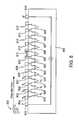
- the inventive blood flow sensorconsists of a silicon chip with 5 or more electrodes located on its surface. Two of the electrodes, which may be the outermost electrodes, are used as a current source to drive current through the fluid. The other electrodes are used as voltage sensing electrodes. The voltage difference can be measured across neighboring electrodes. Alternatively, the voltage difference can be measured across any two electrodes.
- the electrodescan be spaced equally apart along the sensor, to give uniformly spaced data points, and allow for easier processing of the data. Alternatively, the electrodes can be spaced at different intervals to include only desired data points.
- the sensorcan be placed anywhere in the body to measure blood flow. As red blood cells pass each pair of electrodes, the resistance between the pair of electrodes is increased. This creates a spike in the voltage measured across the electrodes. Observing the voltage signal at the first set of electrodes, there will be a spike for each red blood cell.
- the processing circuitrycan count the voltage spikes, giving an indication of hematocrit on a continuous, in vivo basis.
- the voltage signalcan be measured between every pair of neighboring electrodes. Assuming there is not much change in the cloud of red blood cells, the spike pattern will be similar but delayed by a time, t, at a pair of electrodes further in the direction of blood flow, at a distance, d, from the first electrode pair.
- the blood velocity and hematocritcan be determined at many different points along the sensor.
- the spacing between electrodescan be provided which is similar to the size of a red blood cell to give the clearest spike for each cell. This allows for the most accurate measure of hematocrit.
- blood velocitycan be accurately determined with a much higher spacing using the inventive method.
- the voltage signalwould not have as many clear spikes using this alternate approach, the signals at different electrode pairs can still be correlated accurately.
- FIG. 8shows an embodiment of the inventive blood flow sensor, which consists of a silicon chip 801 with fourteen electrodes 803 - 816 located on its surface. Each electrode 803 - 816 is separated by a uniform distance, d. The outermost electrodes 803 and 816 are configured as a current source to drive current through the fluid. The other electrodes 804 - 815 are configured as voltage sensing electrodes. The voltage signals at all neighboring electrodes are passed through differential amplifiers 819 - 829 to obtain the voltage difference between the two electrodes. The voltage at the output of each amplifier 819 - 829 is passed to processing circuitry, where it is analyzed. As red blood cells 831 pass each pair of electrodes, the resistance between the pair of electrodes is increased. This creates a spike in the voltage difference measured between the electrodes.
- FIG. 9Ashows theoretical data for the voltage signal measured by the device shown in FIG. 8 at the output of amplifier 819 , which outputs the voltage difference between electrodes 804 and 805 .
- This waveform 901would be expected when a group of red blood cells passes the pace between electrodes 804 and 805 .
- Each peak 905 - 909is caused by one red blood cell passing electrodes 804 and 805 .
- the control circuitrycounts the peaks to give an estimation of hematocrit on a continuous, in vivo basis.
- FIG. 9Bshows theoretical data for the voltage signal measured by the device shown in FIG. 8 at the output of amplifier 820 , which outputs the voltage difference between electrodes 805 and 806 .
- This waveform 911would be expected when the same group of cells that created waveform 901 from FIG. 9A passes the space between electrodes 805 and 806 .
- Waveform 911is very similar to waveform 901 in FIG. 9A , except it is delayed by a time, t 1 .
- the process circuitryreceives waveforms 901 and 911 and correlates them using techniques well known in the art to recognize the analogous waveform, and find the time difference, t 1 .
- FIG. 9Cshows theoretical data for the voltage signal measured by the device shown in FIG. 8 at the output of amplifier 821 , which outputs the voltage difference between electrodes 806 and 807 .
- This waveform 913would be expected when the same group of cells that created waveform 901 from FIG. 9A passes the space between electrodes 806 and 807 .
- the waveformis very similar to waveform 901 , except that it is delayed by a time t 2 .
- the correlation techniquesare used to compare waveform 913 with either waveform 901 from FIG. 9A , waveform 911 from FIG. 9B , or both. This will be used to calculate t 2 .
- This inventive techniquecan be used to calculate hematocrit and blood velocity at and between every electrode pair along the length of the sensor.
- the spacing between the two data pointscan be varied depending on the desired information.
- Each successive neighboring paircan be used to track changes in blood flow over the length of the sensor.
- two electrode pairs that are spaced further apartmay be used.
- the shape of the spikescan be used to determine the size of the cells. A larger cell would produce a broader spike, while a smaller cell would produce a sharper spike.
- statisticssuch as the relative size of the minor axis of the cell to the major axis of the cell can be generated. This information can be used to evaluate the health of the cells.
- a central data collection devicee.g., a pacemaker control can
- the datamay be processed and/or forwarded to an external device for processing.
- the data collection devicecan be internal or external as desired; for instance, a collection device can be implemented as a watch or belt with electrodes that contact the patient's skin while the patient wears the device.
- An external devicemay provide audible and/or visual information to the patient or clinician, including alerts, measurement data and the like.
- Such a devicemay also include a communication port via which the device can be connected to a computer to which data collected by the device can be transferred.
- the senor embodiment described hereincan be implanted and operated for an indefinite period, including while the patient goes about his or her normal activities. Depending on how power is supplied to the sensor, the sensor can be operated continuously or on some duty cycle selected by the clinician. Data reported by the sensors can be stored in the collection device until the patient visits the clinician, at which time the clinician can read out the data and evaluate the patient's condition. In some embodiments, the collection device may also be able to generate an audible or visible alert to the patient if data indicating an abnormal condition are received; the alert prompts the patient to seek medical care.
- a number of physiological parameterscan be derived from blood resistivity measurements reported by sensors of the type described herein. These parameters can be used to diagnose a patient's condition, determine a treatment plan, and modify the treatment plan based on the response as determined from continued use of the sensors.
- stroke volumerefers to the amount of blood moved into and out of the heart over a cardiac cycle.
- a sensoris positioned to detect flow velocity of blood through a blood vessel located near the heart. From the perspective of accuracy, the aorta is a desirable location for implanting the sensor; however, medical considerations may make an implant into the aorta impractical.
- the vena cavawhich is generally accessible during catheterization procedures, is another suitable site for the implant.
- the diameter or cross-sectional area of the selected blood vessel at the implant siteis measured, e.g., directly (while the vessel is being accessed for the implant), by statistical estimation (e.g., based on an average over a suitable population of patients), by electrical tomography, or by any other suitable technique.
- the flow rate multiplied by the cross sectional areaprovides a flux measurement that can be integrated over the duration of a cardiac cycle to determine the total volume of blood passing through the vessel. Stroke volume provides one measure of heart health.
- blood vessel blockagescan be detected by implanting a flow sensor in any location where development of a blockage (or worsening of a partial blockage) is anticipated. Occlusion of the blood vessel will affect the blood velocity profile for the vessel, with the effect being stronger as the degree of occlusion increases.
- a flow sensor as described hereincan be used to monitor a blood vessel for blockages, either acute or chronic. For example, an acute thrombosis could be detected in this manner, with detection triggering an alert to the patient and/or automatic release of an anti-coagulant. Chronic growth of a plaque deposit in a blood vessel can also be measured by detecting changes in the resistivity as the flow rate changes over time.
- Additional metrics of heart healthcan also be defined. For example, as noted above, blood resistivity varies directly with flow velocity and inversely with hematocrit. As a result, it can be difficult to separate the effects of flow velocity and hematocrit on a resistivity measurement. In the short term, hematocrit is effectively constant and this is not an issue, but for longer term monitoring, the possible variation of hematocrit and its effect on resistivity should be considered. Metrics in which the hematocrit dependence is removed (e.g., by cancellation in a ratio) can advantageously be used to facilitate long-term monitoring of changes in heart health. For instance, if ⁇ max is the maximum flow velocity during a cardiac cycle and ⁇ min is the minimum flow velocity, one can define a flow ratio ⁇ as:
- ⁇v ma ⁇ ⁇ x v m ⁇ ⁇ i ⁇ ⁇ n . ( 5 )
- resistivity-based blood flow sensorse.g., as described above
- Other similar metricscould also be constructed and validated through clinical observation.
- hematocrit and floware measured separately.
- hematocritis determined by measuring resistivity in a region where flow velocity is known (and preferably fixed).
- small flow sensorsdetect the passage of individual red blood cells. For instance, the sensor embodiment shown in FIG. 1 above can be fabricated on a semiconductor substrate with the distance S in the 6-8 micron range.
- the voltage V measured by a device of this kindis given by:
- V⁇ ⁇ ⁇ I 2 ⁇ ⁇ ⁇ ⁇ S , ( 6 )
- blood flow sensorsare used in detection of injury (e.g., bleeding) and wound management. Any injury that results in internal or external bleeding will also change the flow profile in blood vessels surrounding the injury site. According, flow sensors can be implanted at or near an injury site or surgical site to detect whether bleeding has stopped. In the case of surgical sites, it may be useful to implant such sensors to detect internal bleeding after the surgery so that action can be taken even before symptoms are apparent.
- Still other embodimentsuse blood flow as an indicator of physiological activity in body tissues or organs to which blood is supplied. It is generally known that as systems, organs or tissues in the body become more active, blood flow to those locations increases in order to satisfy the increased metabolic demand. For instance, blood flow to various areas of the brain increases when those areas are active (e.g., during various kinds of mental activity). Blood flow sensors in or around the brain could be used to detect such activity and to associate various mental activities with the relevant regions of the brain. Absence of increased blood flow in situations where it would be expected may also indicate an abnormality.
- sensors as described hereinmight be used to construct a “lie detector.” By studying subjects engaged in deceptive and non-deceptive behavior, it may be possible to identify characteristic differences in blood flow patterns (e.g., certain areas of the brain might become more active); these differences could be used to detect deceptive behavior in other subjects.
- stomach and intestinesreceive increased blood flow during digestion; thus, digestive processes can be detected and monitored using sensors placed in gastric blood vessels.
- Abnormal tissuessuch as malignant tumors
- blood flow to the tumorwill depend on the size of the tumor and whether it is growing or shrinking.
- Changes in blood flow in a vessel feeding the tumorcan provide an indication as to how effectively a given course of treatment is working. This information can be used by a clinician in determining whether to continue or change the treatment.
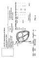
- FIG. 4illustrates an experimental setup for testing a blood resistivity sensor according to an embodiment of the present invention.
- a pigas the test subject, one sensor (with a pair of electrodes) was placed in the superior vena cava (SVC) and another in the inferior vena cava (IVC), and a two-point measurement was performed. Constant voltage was applied between each pair of electrodes, and the voltage across a 10-ohm resistor in series was measured. The measured voltage is proportional to current and thus inversely proportional to impedance between the two electrodes in the pair.
- SVCsuperior vena cava
- IVCinferior vena cava
- FIGS. 5 and 6are results obtained from experiments in an anesthetized pig.
- the top panel (S 1 )corresponds to the SVC
- the second panel (S 2 )corresponds to the IVC.
- the bottom panel (ECG)corresponds to an electrocardiogram taken at the same time as the data. Panels in the left column show a time trace of about 12 seconds, and the right column shows data for several cardiac cycles (as determined from the ECG readings) overlaid.
- FIG. 7shows results from an experiment in which a balloon was inflated to occlude the IVC, blocking blood flow.
- the experimentbegan with the balloon deflated; after about 2 seconds, the balloon was inflated over 2-3 seconds, held full for 2 seconds, then deflated over 2-3 seconds.
- the SVC panel (S 1 )shows that the flow rate in the SVC generally increased when the IVC was blocked, since the SVC must provide more blood to fill the heart when the IVC is blocked. When the IVC was unblocked, restoring the flow, the flow rate in the SVC decreased. The dip at around 4 seconds is believed to be due to a systemic effect: the increased flow “sucked the SVC dry” until hemodynamic systems could compensate.
- the IVC panel(S 2 ) shows that the flow rate in the IVC spiked as the vessel was pinched off by the inflating balloon, with blood rushing through the narrow opening between the vessel wall and the balloon.
- the blood flowgenerally decreased below baseline (see FIGS. 5 and 6 ) when the vessel was completely blocked, although the effect is not as dramatic as might have been expected.
- the resultsalso show that the variation of flow rate within a cardiac cycle is decreased when the vessel is occluded.
- measuring electrical resistivity (or conductivity) as described hereinis a viable tool for monitoring the patient's circulatory system, including the development of vessel blockages.
Landscapes
- Health & Medical Sciences (AREA)
- Life Sciences & Earth Sciences (AREA)
- Physics & Mathematics (AREA)
- Engineering & Computer Science (AREA)
- Heart & Thoracic Surgery (AREA)
- Surgery (AREA)
- Biophysics (AREA)
- Pathology (AREA)
- Veterinary Medicine (AREA)
- Biomedical Technology (AREA)
- Public Health (AREA)
- Medical Informatics (AREA)
- Molecular Biology (AREA)
- General Health & Medical Sciences (AREA)
- Animal Behavior & Ethology (AREA)
- Physiology (AREA)
- Hematology (AREA)
- Cardiology (AREA)
- Computer Networks & Wireless Communication (AREA)
- Optics & Photonics (AREA)
- Measuring Pulse, Heart Rate, Blood Pressure Or Blood Flow (AREA)
Abstract
Description
v=d/t (1)
v=d/t1 (2)
v=d/(t2−t1) (3)
v=2d/t2 (4)
One might expect η to be large for a healthy heart and small for a weak or diseased heart. An advantage of such a metric is that in resistivity-based blood flow sensors (e.g., as described above), it can be difficult to disentangle the effects of flow velocity and hematocrit; in Eq. (5), any hematocrit dependencies would cancel out. Other similar metrics could also be constructed and validated through clinical observation.
Claims (17)
Priority Applications (1)
| Application Number | Priority Date | Filing Date | Title |
|---|---|---|---|
| US11/897,942US8172762B2 (en) | 2006-09-01 | 2007-08-31 | Simultaneous blood flow and hematocrit sensor |
Applications Claiming Priority (2)
| Application Number | Priority Date | Filing Date | Title |
|---|---|---|---|
| US82430906P | 2006-09-01 | 2006-09-01 | |
| US11/897,942US8172762B2 (en) | 2006-09-01 | 2007-08-31 | Simultaneous blood flow and hematocrit sensor |
Publications (2)
| Publication Number | Publication Date |
|---|---|
| US20080058630A1 US20080058630A1 (en) | 2008-03-06 |
| US8172762B2true US8172762B2 (en) | 2012-05-08 |
Family
ID=39152745
Family Applications (1)
| Application Number | Title | Priority Date | Filing Date |
|---|---|---|---|
| US11/897,942Expired - Fee RelatedUS8172762B2 (en) | 2006-09-01 | 2007-08-31 | Simultaneous blood flow and hematocrit sensor |
Country Status (1)
| Country | Link |
|---|---|
| US (1) | US8172762B2 (en) |
Cited By (18)
| Publication number | Priority date | Publication date | Assignee | Title |
|---|---|---|---|---|
| US20130165760A1 (en)* | 2011-12-14 | 2013-06-27 | Paul J. Erlinger | Devices for determining the relative spatial change in subsurface resistivities across frequencies in tissue |
| US9072906B2 (en) | 2008-07-30 | 2015-07-07 | Ecole Polytechnique Federale De Lausanne | Apparatus and method for optimized stimulation of a neurological target |
| US9192767B2 (en) | 2009-12-01 | 2015-11-24 | Ecole Polytechnique Federale De Lausanne | Microfabricated surface neurostimulation device and methods of making and using the same |
| US9403011B2 (en) | 2014-08-27 | 2016-08-02 | Aleva Neurotherapeutics | Leadless neurostimulator |
| US9440082B2 (en) | 2008-11-12 | 2016-09-13 | Ecole Polytechnique Federale De Lausanne | Microfabricated neurostimulation device |
| US9474894B2 (en) | 2014-08-27 | 2016-10-25 | Aleva Neurotherapeutics | Deep brain stimulation lead |
| US9549708B2 (en) | 2010-04-01 | 2017-01-24 | Ecole Polytechnique Federale De Lausanne | Device for interacting with neurological tissue and methods of making and using the same |
| US9585593B2 (en) | 2009-11-18 | 2017-03-07 | Chung Shing Fan | Signal distribution for patient-electrode measurements |
| US9615767B2 (en) | 2009-10-26 | 2017-04-11 | Impedimed Limited | Fluid level indicator determination |
| US9724012B2 (en) | 2005-10-11 | 2017-08-08 | Impedimed Limited | Hydration status monitoring |
| US9925376B2 (en) | 2014-08-27 | 2018-03-27 | Aleva Neurotherapeutics | Treatment of autoimmune diseases with deep brain stimulation |
| US10307074B2 (en) | 2007-04-20 | 2019-06-04 | Impedimed Limited | Monitoring system and probe |
| US10966620B2 (en) | 2014-05-16 | 2021-04-06 | Aleva Neurotherapeutics Sa | Device for interacting with neurological tissue and methods of making and using the same |
| US11266830B2 (en) | 2018-03-02 | 2022-03-08 | Aleva Neurotherapeutics | Neurostimulation device |
| US11311718B2 (en) | 2014-05-16 | 2022-04-26 | Aleva Neurotherapeutics Sa | Device for interacting with neurological tissue and methods of making and using the same |
| US11476952B2 (en)* | 2005-04-28 | 2022-10-18 | Otsuka Pharmaceutical Co., Ltd. | Pharma-informatics system |
| US11737678B2 (en) | 2005-07-01 | 2023-08-29 | Impedimed Limited | Monitoring system |
| US12318198B2 (en)* | 2016-09-27 | 2025-06-03 | Itamar Medical Ltd. | Systems and methods for biological metrics measurement |
Families Citing this family (9)
| Publication number | Priority date | Publication date | Assignee | Title |
|---|---|---|---|---|
| EP2063766B1 (en)* | 2006-09-06 | 2017-01-18 | Innurvation, Inc. | Ingestible low power sensor device and system for communicating with same |
| DE102008040788A1 (en)* | 2008-07-28 | 2010-02-11 | Biotronik Crm Patent Ag | Apparatus and method for detecting the flow rate of a bloodstream and cardiovascular assistance apparatus |
| DK2346395T3 (en)* | 2008-09-22 | 2018-06-06 | Cheetah Medical Inc | SYSTEM AND PROCEDURE FOR DETERMINING BLOOD FLOW |
| US8480581B2 (en)* | 2009-03-24 | 2013-07-09 | Cardiac Pacemakers, Inc. | Systems and methods for anemia detection, monitoring, and treatment |
| US20100312128A1 (en)* | 2009-06-09 | 2010-12-09 | Edward Karst | Systems and methods for monitoring blood partitioning and organ function |
| US10485481B2 (en)* | 2015-03-20 | 2019-11-26 | The Trustees Of Dartmouth College | Systems and methods for enhancing uptake of therapeutic agent from bloodstream into disease site |
| CN106037757B (en)* | 2016-07-13 | 2023-10-17 | 心擎医疗(苏州)股份有限公司 | In-vivo platelet instant label-free detection system and detection method |
| CN117897094A (en)* | 2021-08-23 | 2024-04-16 | C·R·巴德股份有限公司 | Urine output monitoring system |
| US20250255554A1 (en)* | 2022-04-22 | 2025-08-14 | Medtronic, Inc. | Determination of cardiac flow rate with an implantable medical device |
Citations (47)
| Publication number | Priority date | Publication date | Assignee | Title |
|---|---|---|---|---|
| US3949388A (en) | 1972-11-13 | 1976-04-06 | Monitron Industries, Inc. | Physiological sensor and transmitter |
| US3996925A (en)* | 1975-05-05 | 1976-12-14 | Ljubomir Djordjevich | System for determining characteristics of blood flow |
| US4635296A (en) | 1985-02-22 | 1987-01-06 | Transkinetic Systems, Inc. | Wide bandwidth ultra high stability FM telemetry transmitter |
| US4844076A (en) | 1988-08-26 | 1989-07-04 | The Johns Hopkins University | Ingestible size continuously transmitting temperature monitoring pill |
| US5099227A (en) | 1989-07-18 | 1992-03-24 | Indala Corporation | Proximity detecting apparatus |
| US5331966A (en) | 1991-04-05 | 1994-07-26 | Medtronic, Inc. | Subcutaneous multi-electrode sensing system, method and pacer |
| US5513637A (en) | 1992-09-29 | 1996-05-07 | Hdc Corporation | Method and apparatus for determining the position of catheters, tubes, placement guidewires and implantable ports within biological tissue |
| US5630835A (en) | 1995-07-24 | 1997-05-20 | Cardiac Control Systems, Inc. | Method and apparatus for the suppression of far-field interference signals for implantable device data transmission systems |
| US5697958A (en) | 1995-06-07 | 1997-12-16 | Intermedics, Inc. | Electromagnetic noise detector for implantable medical devices |
| US5796827A (en) | 1996-11-14 | 1998-08-18 | International Business Machines Corporation | System and method for near-field human-body coupling for encrypted communication with identification cards |
| US5829444A (en) | 1994-09-15 | 1998-11-03 | Visualization Technology, Inc. | Position tracking and imaging system for use in medical applications |
| US5842977A (en) | 1995-07-24 | 1998-12-01 | The Johns Hopkins University | Multi-channel pill with integrated optical interface |
| US5905261A (en) | 1995-12-01 | 1999-05-18 | Schotland; John Carl | Imaging system and method using direct reconstruction of scattered radiation |
| US5914701A (en)* | 1995-05-08 | 1999-06-22 | Massachusetts Institute Of Technology | Non-contact system for sensing and signalling by externally induced intra-body currents |
| US6009350A (en) | 1998-02-06 | 1999-12-28 | Medtronic, Inc. | Implant device telemetry antenna |
| US6115636A (en) | 1998-12-22 | 2000-09-05 | Medtronic, Inc. | Telemetry for implantable devices using the body as an antenna |
| US6201387B1 (en) | 1997-10-07 | 2001-03-13 | Biosense, Inc. | Miniaturized position sensor having photolithographic coils for tracking a medical probe |
| US6208894B1 (en) | 1997-02-26 | 2001-03-27 | Alfred E. Mann Foundation For Scientific Research And Advanced Bionics | System of implantable devices for monitoring and/or affecting body parameters |
| US6211799B1 (en)* | 1997-11-06 | 2001-04-03 | Massachusetts Institute Of Technology | Method and apparatus for transbody transmission of power and information |
| US6336031B1 (en)* | 1998-12-22 | 2002-01-01 | Nortel Networks Limited | Wireless data transmission over quasi-static electric potential fields |
| US6359597B2 (en) | 2000-07-03 | 2002-03-19 | Yosri Mohamad Taher Haj-Yousef | Method and device for detecting and monitoring concealed bodies and objects |
| US6458086B1 (en)* | 2000-04-05 | 2002-10-01 | Kenneth Lawrence Franco | Implantable blood flow monitoring system |
| US6505072B1 (en) | 2000-11-16 | 2003-01-07 | Cardiac Pacemakers, Inc. | Implantable electronic stimulator having isolation transformer input to telemetry circuits |
| US20030036674A1 (en) | 2001-07-26 | 2003-02-20 | Bouton Chad Edward | Electromagnetic sensors for biological tissue applications and methods for their use |
| US6574510B2 (en) | 2000-11-30 | 2003-06-03 | Cardiac Pacemakers, Inc. | Telemetry apparatus and method for an implantable medical device |
| US20030167000A1 (en) | 2000-02-08 | 2003-09-04 | Tarun Mullick | Miniature ingestible capsule |
| US20030169132A1 (en) | 1996-05-13 | 2003-09-11 | Hex Technology Holdings Limited, Jersey, Channel Islands | Generator of electric and magnetic fields, a corresponding field detector, and a sample analyzer and treatment apparatus incorporating the field generator and/or field detector |
| US6630833B2 (en) | 1994-07-26 | 2003-10-07 | Phase Dynamics, Inc. | Measurement by concentration of a material within a structure |
| US20040004554A1 (en) | 2000-12-08 | 2004-01-08 | Regaswamy Srinivasan | Wireless multi-funtional sensor platform, system containing same and method for its use |
| US20040024309A1 (en) | 1994-09-15 | 2004-02-05 | Ferre Maurice R. | System for monitoring the position of a medical instrument with respect to a patient's body |
| US20040030260A1 (en) | 2002-08-08 | 2004-02-12 | Arx Jeffrey A. Von | Method and system for improved spectral efficiency of far field telemetry in a medical device |
| US6706040B2 (en) | 2001-11-23 | 2004-03-16 | Medlennium Technologies, Inc. | Invasive therapeutic probe |
| US20040102219A1 (en) | 1999-11-29 | 2004-05-27 | Bunton John David | Communications system |
| US6754472B1 (en) | 2000-04-27 | 2004-06-22 | Microsoft Corporation | Method and apparatus for transmitting power and data using the human body |
| US20040123871A1 (en) | 2002-12-31 | 2004-07-01 | Wright J Nelson | Method and apparatus for sensing field strength signals to estimate location of a wireless implantable marker |
| US20040187875A1 (en) | 2001-05-01 | 2004-09-30 | He Sheng Ding | Method and apparatus for altering conduction properties along pathways in the heart and in vessels in conductive communication with the heart. |
| US6809701B2 (en) | 2001-08-03 | 2004-10-26 | Cardiac Pacemakers, Inc. | Circumferential antenna for an implantable medical device |
| US20050075559A1 (en) | 1999-12-21 | 2005-04-07 | Phaeton Research Ltd. | Ingestible device |
| US20050096562A1 (en) | 2003-11-05 | 2005-05-05 | Delalic Z. J. | Implantable telemetric monitoring system, apparatus, and method |
| US20050110700A1 (en) | 2003-11-25 | 2005-05-26 | Starkey Laboratories, Inc. | Enhanced magnetic field communication system |
| US20050134520A1 (en) | 2003-12-22 | 2005-06-23 | Prashant Rawat | Radio frequency antenna in a header of an implantable medical device |
| US20060025661A1 (en)* | 2004-08-02 | 2006-02-02 | Sweeney Robert J | Device for monitoring fluid status |
| US20060178109A1 (en)* | 2003-02-27 | 2006-08-10 | Sony Corporation | Communication system, communication method and communication apparatus |
| US7236821B2 (en)* | 2002-02-19 | 2007-06-26 | Cardiac Pacemakers, Inc. | Chronically-implanted device for sensing and therapy |
| US7245954B2 (en)* | 2003-03-27 | 2007-07-17 | Given Imaging Ltd. | Measuring a gradient in-vivo |
| US20080306359A1 (en)* | 2005-09-01 | 2008-12-11 | Zdeblick Mark J | Medical Diagnostic and Treatment Platform Using Near-Field Wireless Communication of Information Within a Patient's Body |
| US7664476B2 (en)* | 2005-04-18 | 2010-02-16 | Sony Corporation | Human body communication system and communication device |
- 2007
- 2007-08-31USUS11/897,942patent/US8172762B2/ennot_activeExpired - Fee Related
Patent Citations (48)
| Publication number | Priority date | Publication date | Assignee | Title |
|---|---|---|---|---|
| US3949388A (en) | 1972-11-13 | 1976-04-06 | Monitron Industries, Inc. | Physiological sensor and transmitter |
| US3996925A (en)* | 1975-05-05 | 1976-12-14 | Ljubomir Djordjevich | System for determining characteristics of blood flow |
| US4635296A (en) | 1985-02-22 | 1987-01-06 | Transkinetic Systems, Inc. | Wide bandwidth ultra high stability FM telemetry transmitter |
| US4844076A (en) | 1988-08-26 | 1989-07-04 | The Johns Hopkins University | Ingestible size continuously transmitting temperature monitoring pill |
| US5099227A (en) | 1989-07-18 | 1992-03-24 | Indala Corporation | Proximity detecting apparatus |
| US5331966A (en) | 1991-04-05 | 1994-07-26 | Medtronic, Inc. | Subcutaneous multi-electrode sensing system, method and pacer |
| US5513637A (en) | 1992-09-29 | 1996-05-07 | Hdc Corporation | Method and apparatus for determining the position of catheters, tubes, placement guidewires and implantable ports within biological tissue |
| US6630833B2 (en) | 1994-07-26 | 2003-10-07 | Phase Dynamics, Inc. | Measurement by concentration of a material within a structure |
| US5829444A (en) | 1994-09-15 | 1998-11-03 | Visualization Technology, Inc. | Position tracking and imaging system for use in medical applications |
| US20040024309A1 (en) | 1994-09-15 | 2004-02-05 | Ferre Maurice R. | System for monitoring the position of a medical instrument with respect to a patient's body |
| US5914701A (en)* | 1995-05-08 | 1999-06-22 | Massachusetts Institute Of Technology | Non-contact system for sensing and signalling by externally induced intra-body currents |
| US5697958A (en) | 1995-06-07 | 1997-12-16 | Intermedics, Inc. | Electromagnetic noise detector for implantable medical devices |
| US5842977A (en) | 1995-07-24 | 1998-12-01 | The Johns Hopkins University | Multi-channel pill with integrated optical interface |
| US5630835A (en) | 1995-07-24 | 1997-05-20 | Cardiac Control Systems, Inc. | Method and apparatus for the suppression of far-field interference signals for implantable device data transmission systems |
| US5905261A (en) | 1995-12-01 | 1999-05-18 | Schotland; John Carl | Imaging system and method using direct reconstruction of scattered radiation |
| US20030169132A1 (en) | 1996-05-13 | 2003-09-11 | Hex Technology Holdings Limited, Jersey, Channel Islands | Generator of electric and magnetic fields, a corresponding field detector, and a sample analyzer and treatment apparatus incorporating the field generator and/or field detector |
| US5796827A (en) | 1996-11-14 | 1998-08-18 | International Business Machines Corporation | System and method for near-field human-body coupling for encrypted communication with identification cards |
| US6208894B1 (en) | 1997-02-26 | 2001-03-27 | Alfred E. Mann Foundation For Scientific Research And Advanced Bionics | System of implantable devices for monitoring and/or affecting body parameters |
| US6201387B1 (en) | 1997-10-07 | 2001-03-13 | Biosense, Inc. | Miniaturized position sensor having photolithographic coils for tracking a medical probe |
| US6211799B1 (en)* | 1997-11-06 | 2001-04-03 | Massachusetts Institute Of Technology | Method and apparatus for transbody transmission of power and information |
| US6009350A (en) | 1998-02-06 | 1999-12-28 | Medtronic, Inc. | Implant device telemetry antenna |
| US6336031B1 (en)* | 1998-12-22 | 2002-01-01 | Nortel Networks Limited | Wireless data transmission over quasi-static electric potential fields |
| US6115636A (en) | 1998-12-22 | 2000-09-05 | Medtronic, Inc. | Telemetry for implantable devices using the body as an antenna |
| US20040102219A1 (en) | 1999-11-29 | 2004-05-27 | Bunton John David | Communications system |
| US20050075559A1 (en) | 1999-12-21 | 2005-04-07 | Phaeton Research Ltd. | Ingestible device |
| US20030167000A1 (en) | 2000-02-08 | 2003-09-04 | Tarun Mullick | Miniature ingestible capsule |
| US6458086B1 (en)* | 2000-04-05 | 2002-10-01 | Kenneth Lawrence Franco | Implantable blood flow monitoring system |
| US6754472B1 (en) | 2000-04-27 | 2004-06-22 | Microsoft Corporation | Method and apparatus for transmitting power and data using the human body |
| US6359597B2 (en) | 2000-07-03 | 2002-03-19 | Yosri Mohamad Taher Haj-Yousef | Method and device for detecting and monitoring concealed bodies and objects |
| US6505072B1 (en) | 2000-11-16 | 2003-01-07 | Cardiac Pacemakers, Inc. | Implantable electronic stimulator having isolation transformer input to telemetry circuits |
| US6574510B2 (en) | 2000-11-30 | 2003-06-03 | Cardiac Pacemakers, Inc. | Telemetry apparatus and method for an implantable medical device |
| US6766201B2 (en) | 2000-11-30 | 2004-07-20 | Cardiac Pacemakers, Inc. | Telemetry apparatus and method for an implantable medical device |
| US20040004554A1 (en) | 2000-12-08 | 2004-01-08 | Regaswamy Srinivasan | Wireless multi-funtional sensor platform, system containing same and method for its use |
| US20040187875A1 (en) | 2001-05-01 | 2004-09-30 | He Sheng Ding | Method and apparatus for altering conduction properties along pathways in the heart and in vessels in conductive communication with the heart. |
| US20030036674A1 (en) | 2001-07-26 | 2003-02-20 | Bouton Chad Edward | Electromagnetic sensors for biological tissue applications and methods for their use |
| US6809701B2 (en) | 2001-08-03 | 2004-10-26 | Cardiac Pacemakers, Inc. | Circumferential antenna for an implantable medical device |
| US6706040B2 (en) | 2001-11-23 | 2004-03-16 | Medlennium Technologies, Inc. | Invasive therapeutic probe |
| US7236821B2 (en)* | 2002-02-19 | 2007-06-26 | Cardiac Pacemakers, Inc. | Chronically-implanted device for sensing and therapy |
| US20040030260A1 (en) | 2002-08-08 | 2004-02-12 | Arx Jeffrey A. Von | Method and system for improved spectral efficiency of far field telemetry in a medical device |
| US20040123871A1 (en) | 2002-12-31 | 2004-07-01 | Wright J Nelson | Method and apparatus for sensing field strength signals to estimate location of a wireless implantable marker |
| US20060178109A1 (en)* | 2003-02-27 | 2006-08-10 | Sony Corporation | Communication system, communication method and communication apparatus |
| US7245954B2 (en)* | 2003-03-27 | 2007-07-17 | Given Imaging Ltd. | Measuring a gradient in-vivo |
| US20050096562A1 (en) | 2003-11-05 | 2005-05-05 | Delalic Z. J. | Implantable telemetric monitoring system, apparatus, and method |
| US20050110700A1 (en) | 2003-11-25 | 2005-05-26 | Starkey Laboratories, Inc. | Enhanced magnetic field communication system |
| US20050134520A1 (en) | 2003-12-22 | 2005-06-23 | Prashant Rawat | Radio frequency antenna in a header of an implantable medical device |
| US20060025661A1 (en)* | 2004-08-02 | 2006-02-02 | Sweeney Robert J | Device for monitoring fluid status |
| US7664476B2 (en)* | 2005-04-18 | 2010-02-16 | Sony Corporation | Human body communication system and communication device |
| US20080306359A1 (en)* | 2005-09-01 | 2008-12-11 | Zdeblick Mark J | Medical Diagnostic and Treatment Platform Using Near-Field Wireless Communication of Information Within a Patient's Body |
Cited By (36)
| Publication number | Priority date | Publication date | Assignee | Title |
|---|---|---|---|---|
| US11476952B2 (en)* | 2005-04-28 | 2022-10-18 | Otsuka Pharmaceutical Co., Ltd. | Pharma-informatics system |
| US11737678B2 (en) | 2005-07-01 | 2023-08-29 | Impedimed Limited | Monitoring system |
| US9724012B2 (en) | 2005-10-11 | 2017-08-08 | Impedimed Limited | Hydration status monitoring |
| US11612332B2 (en) | 2005-10-11 | 2023-03-28 | Impedimed Limited | Hydration status monitoring |
| US10307074B2 (en) | 2007-04-20 | 2019-06-04 | Impedimed Limited | Monitoring system and probe |
| US10952627B2 (en) | 2008-07-30 | 2021-03-23 | Ecole Polytechnique Federale De Lausanne | Apparatus and method for optimized stimulation of a neurological target |
| US10166392B2 (en) | 2008-07-30 | 2019-01-01 | Ecole Polytechnique Federale De Lausanne | Apparatus and method for optimized stimulation of a neurological target |
| US9072906B2 (en) | 2008-07-30 | 2015-07-07 | Ecole Polytechnique Federale De Lausanne | Apparatus and method for optimized stimulation of a neurological target |
| US9440082B2 (en) | 2008-11-12 | 2016-09-13 | Ecole Polytechnique Federale De Lausanne | Microfabricated neurostimulation device |
| US11123548B2 (en) | 2008-11-12 | 2021-09-21 | Ecole Polytechnique Federale De Lausanne | Microfabricated neurostimulation device |
| US10406350B2 (en) | 2008-11-12 | 2019-09-10 | Ecole Polytechnique Federale De Lausanne | Microfabricated neurostimulation device |
| US9615767B2 (en) | 2009-10-26 | 2017-04-11 | Impedimed Limited | Fluid level indicator determination |
| US9585593B2 (en) | 2009-11-18 | 2017-03-07 | Chung Shing Fan | Signal distribution for patient-electrode measurements |
| US9192767B2 (en) | 2009-12-01 | 2015-11-24 | Ecole Polytechnique Federale De Lausanne | Microfabricated surface neurostimulation device and methods of making and using the same |
| US9604055B2 (en) | 2009-12-01 | 2017-03-28 | Ecole Polytechnique Federale De Lausanne | Microfabricated surface neurostimulation device and methods of making and using the same |
| US11766560B2 (en) | 2010-04-01 | 2023-09-26 | Ecole Polytechnique Federale De Lausanne | Device for interacting with neurological tissue and methods of making and using the same |
| US9549708B2 (en) | 2010-04-01 | 2017-01-24 | Ecole Polytechnique Federale De Lausanne | Device for interacting with neurological tissue and methods of making and using the same |
| US10695556B2 (en) | 2010-04-01 | 2020-06-30 | Ecole Polytechnique Federale De Lausanne | Device for interacting with neurological tissue and methods of making and using the same |
| US20130165760A1 (en)* | 2011-12-14 | 2013-06-27 | Paul J. Erlinger | Devices for determining the relative spatial change in subsurface resistivities across frequencies in tissue |
| US9149225B2 (en) | 2011-12-14 | 2015-10-06 | Intesection Medical, Inc. | Methods for determining the relative spatial change in subsurface resistivities across frequencies in tissue |
| US8700121B2 (en)* | 2011-12-14 | 2014-04-15 | Intersection Medical, Inc. | Devices for determining the relative spatial change in subsurface resistivities across frequencies in tissue |
| US11311718B2 (en) | 2014-05-16 | 2022-04-26 | Aleva Neurotherapeutics Sa | Device for interacting with neurological tissue and methods of making and using the same |
| US10966620B2 (en) | 2014-05-16 | 2021-04-06 | Aleva Neurotherapeutics Sa | Device for interacting with neurological tissue and methods of making and using the same |
| US10201707B2 (en) | 2014-08-27 | 2019-02-12 | Aleva Neurotherapeutics | Treatment of autoimmune diseases with deep brain stimulation |
| US10441779B2 (en) | 2014-08-27 | 2019-10-15 | Aleva Neurotherapeutics | Deep brain stimulation lead |
| US10065031B2 (en) | 2014-08-27 | 2018-09-04 | Aleva Neurotherapeutics | Deep brain stimulation lead |
| US11167126B2 (en) | 2014-08-27 | 2021-11-09 | Aleva Neurotherapeutics | Deep brain stimulation lead |
| US9925376B2 (en) | 2014-08-27 | 2018-03-27 | Aleva Neurotherapeutics | Treatment of autoimmune diseases with deep brain stimulation |
| US9889304B2 (en) | 2014-08-27 | 2018-02-13 | Aleva Neurotherapeutics | Leadless neurostimulator |
| US9572985B2 (en) | 2014-08-27 | 2017-02-21 | Aleva Neurotherapeutics | Method of manufacturing a thin film leadless neurostimulator |
| US11730953B2 (en) | 2014-08-27 | 2023-08-22 | Aleva Neurotherapeutics | Deep brain stimulation lead |
| US9474894B2 (en) | 2014-08-27 | 2016-10-25 | Aleva Neurotherapeutics | Deep brain stimulation lead |
| US9403011B2 (en) | 2014-08-27 | 2016-08-02 | Aleva Neurotherapeutics | Leadless neurostimulator |
| US12318198B2 (en)* | 2016-09-27 | 2025-06-03 | Itamar Medical Ltd. | Systems and methods for biological metrics measurement |
| US11266830B2 (en) | 2018-03-02 | 2022-03-08 | Aleva Neurotherapeutics | Neurostimulation device |
| US11738192B2 (en) | 2018-03-02 | 2023-08-29 | Aleva Neurotherapeutics | Neurostimulation device |
Also Published As
| Publication number | Publication date |
|---|---|
| US20080058630A1 (en) | 2008-03-06 |
Similar Documents
| Publication | Publication Date | Title |
|---|---|---|
| US8172762B2 (en) | Simultaneous blood flow and hematocrit sensor | |
| US7899526B2 (en) | Portable device for monitoring electrocardiographic signals and indices of blood flow | |
| US11529065B2 (en) | Methods and devices of cardiac tissue monitoring and analysis | |
| US8547248B2 (en) | Implantable zero-wire communications system | |
| Summers et al. | Bench to bedside: electrophysiologic and clinical principles of noninvasive hemodynamic monitoring using impedance cardiography | |
| EP2117639B1 (en) | Detect eating to initiate gastric pacing | |
| AU2020289809A1 (en) | Non-invasive detection of the backflow of urine | |
| US20090306524A1 (en) | Sensor for detecting the passing of a pulse wave from a subject's arterial system | |
| US7894884B2 (en) | System and method for ischemia classification with implantable medical device | |
| GB2563155A (en) | Implantable devices and related methods for heart failure monitoring | |
| CA2583526A1 (en) | Thoracic impedance monitor and electrode array and method of use | |
| US8965493B2 (en) | Electromedical implant and monitoring system | |
| JP2012520157A (en) | Volume detection | |
| CN101484068A (en) | Wearable blood pressure monitoring system | |
| KR102830485B1 (en) | Monitoring device inserted into human body and operating method thereof | |
| US8798723B2 (en) | System and method for ischemia classification with implantable medical device | |
| US20240156406A1 (en) | Systems and methods for measuring extravascular lung water | |
| US20190159693A1 (en) | Direct electrocardiography monitoring for atrial fibrillation detection | |
| Kong et al. | Design and initial evaluation of an implantable sonomicrometer and cw doppler flowmeter for simultaneous recordings with a multichannel telemetry system | |
| IL239240A (en) | Methods and systems for monitoring intrabody tissues |
Legal Events
| Date | Code | Title | Description |
|---|---|---|---|
| AS | Assignment | Owner name:PROTEUS BIOMEDICAL, INC., CALIFORNIA Free format text:ASSIGNMENT OF ASSIGNORS INTEREST;ASSIGNOR:ROBERTSON, TIMOTHY L.;REEL/FRAME:020563/0086 Effective date:20071018 | |
| FEPP | Fee payment procedure | Free format text:PAYOR NUMBER ASSIGNED (ORIGINAL EVENT CODE: ASPN); ENTITY STATUS OF PATENT OWNER: LARGE ENTITY | |
| ZAAA | Notice of allowance and fees due | Free format text:ORIGINAL CODE: NOA | |
| ZAAB | Notice of allowance mailed | Free format text:ORIGINAL CODE: MN/=. | |
| STCF | Information on status: patent grant | Free format text:PATENTED CASE | |
| AS | Assignment | Owner name:PROTEUS DIGITAL HEALTH, INC., CALIFORNIA Free format text:CHANGE OF NAME;ASSIGNOR:PROTEUS BIOMEDICAL, INC.;REEL/FRAME:029228/0436 Effective date:20120705 | |
| FPAY | Fee payment | Year of fee payment:4 | |
| FEPP | Fee payment procedure | Free format text:MAINTENANCE FEE REMINDER MAILED (ORIGINAL EVENT CODE: REM.); ENTITY STATUS OF PATENT OWNER: LARGE ENTITY | |
| FEPP | Fee payment procedure | Free format text:7.5 YR SURCHARGE - LATE PMT W/IN 6 MO, LARGE ENTITY (ORIGINAL EVENT CODE: M1555); ENTITY STATUS OF PATENT OWNER: LARGE ENTITY | |
| MAFP | Maintenance fee payment | Free format text:PAYMENT OF MAINTENANCE FEE, 8TH YEAR, LARGE ENTITY (ORIGINAL EVENT CODE: M1552); ENTITY STATUS OF PATENT OWNER: LARGE ENTITY Year of fee payment:8 | |
| FEPP | Fee payment procedure | Free format text:MAINTENANCE FEE REMINDER MAILED (ORIGINAL EVENT CODE: REM.); ENTITY STATUS OF PATENT OWNER: LARGE ENTITY | |
| LAPS | Lapse for failure to pay maintenance fees | Free format text:PATENT EXPIRED FOR FAILURE TO PAY MAINTENANCE FEES (ORIGINAL EVENT CODE: EXP.); ENTITY STATUS OF PATENT OWNER: LARGE ENTITY | |
| STCH | Information on status: patent discontinuation | Free format text:PATENT EXPIRED DUE TO NONPAYMENT OF MAINTENANCE FEES UNDER 37 CFR 1.362 | |
| FP | Lapsed due to failure to pay maintenance fee | Effective date:20240508 |