US8172747B2 - Balloon visualization for traversing a tissue wall - Google Patents
Balloon visualization for traversing a tissue wallDownload PDFInfo
- Publication number
- US8172747B2 US8172747B2US10/949,032US94903204AUS8172747B2US 8172747 B2US8172747 B2US 8172747B2US 94903204 AUS94903204 AUS 94903204AUS 8172747 B2US8172747 B2US 8172747B2
- Authority
- US
- United States
- Prior art keywords
- balloon
- tissue wall
- tissue
- traversing
- catheter
- Prior art date
- Legal status (The legal status is an assumption and is not a legal conclusion. Google has not performed a legal analysis and makes no representation as to the accuracy of the status listed.)
- Active, expires
Links
- 238000012800visualizationMethods0.000titleclaimsabstractdescription23
- 238000003384imaging methodMethods0.000claimsabstractdescription47
- 238000000034methodMethods0.000claimsabstractdescription24
- QVGXLLKOCUKJST-UHFFFAOYSA-Natomic oxygenChemical compound[O]QVGXLLKOCUKJST-UHFFFAOYSA-N0.000claimsabstractdescription9
- 229910052760oxygenInorganic materials0.000claimsabstractdescription9
- 239000001301oxygenSubstances0.000claimsabstractdescription9
- 238000012544monitoring processMethods0.000claimsabstractdescription7
- 239000013307optical fiberSubstances0.000claimsdescription10
- 210000003157atrial septumAnatomy0.000claimsdescription9
- 239000012530fluidSubstances0.000claimsdescription9
- 238000004513sizingMethods0.000claimsdescription6
- FAPWRFPIFSIZLT-UHFFFAOYSA-MSodium chlorideChemical compound[Na+].[Cl-]FAPWRFPIFSIZLT-UHFFFAOYSA-M0.000claimsdescription5
- 239000011780sodium chlorideSubstances0.000claimsdescription5
- 239000008280bloodSubstances0.000claimsdescription4
- 210000004369bloodAnatomy0.000claimsdescription4
- 210000005246left atriumAnatomy0.000claimsdescription3
- 238000001514detection methodMethods0.000claimsdescription2
- 210000005245right atriumAnatomy0.000claimsdescription2
- 230000005540biological transmissionEffects0.000description8
- 239000000463materialSubstances0.000description5
- 230000005855radiationEffects0.000description5
- CURLTUGMZLYLDI-UHFFFAOYSA-NCarbon dioxideChemical compoundO=C=OCURLTUGMZLYLDI-UHFFFAOYSA-N0.000description4
- 238000012790confirmationMethods0.000description4
- 238000007796conventional methodMethods0.000description4
- 238000002594fluoroscopyMethods0.000description4
- 238000002604ultrasonographyMethods0.000description4
- 238000005452bendingMethods0.000description3
- 238000005516engineering processMethods0.000description3
- 229910002092carbon dioxideInorganic materials0.000description2
- 239000001569carbon dioxideSubstances0.000description2
- 239000002872contrast mediaSubstances0.000description2
- 238000011010flushing procedureMethods0.000description2
- 238000005286illuminationMethods0.000description2
- 239000011261inert gasSubstances0.000description2
- 238000002329infrared spectrumMethods0.000description2
- 238000012986modificationMethods0.000description2
- 230000004048modificationEffects0.000description2
- 230000037361pathwayEffects0.000description2
- 229920003229poly(methyl methacrylate)Polymers0.000description2
- 239000004926polymethyl methacrylateSubstances0.000description2
- 238000005070samplingMethods0.000description2
- 239000003381stabilizerSubstances0.000description2
- ZCYVEMRRCGMTRW-UHFFFAOYSA-N7553-56-2Chemical compound[I]ZCYVEMRRCGMTRW-UHFFFAOYSA-N0.000description1
- 241001465754MetazoaSpecies0.000description1
- 239000004677NylonSubstances0.000description1
- 239000004642PolyimideSubstances0.000description1
- 239000000853adhesiveSubstances0.000description1
- 230000001070adhesive effectEffects0.000description1
- 238000013459approachMethods0.000description1
- 230000001746atrial effectEffects0.000description1
- 210000004204blood vesselAnatomy0.000description1
- 238000013098chemical test methodMethods0.000description1
- 238000004891communicationMethods0.000description1
- 230000000694effectsEffects0.000description1
- 239000003365glass fiberSubstances0.000description1
- 238000003331infrared imagingMethods0.000description1
- 239000007924injectionSubstances0.000description1
- 238000002347injectionMethods0.000description1
- 229910052740iodineInorganic materials0.000description1
- 239000011630iodineSubstances0.000description1
- WABPQHHGFIMREM-UHFFFAOYSA-Nlead(0)Chemical compound[Pb]WABPQHHGFIMREM-UHFFFAOYSA-N0.000description1
- 238000004519manufacturing processMethods0.000description1
- 238000005259measurementMethods0.000description1
- 229920001778nylonPolymers0.000description1
- 230000003287optical effectEffects0.000description1
- 229920001721polyimidePolymers0.000description1
- 229920000642polymerPolymers0.000description1
- 238000002106pulse oximetryMethods0.000description1
- 239000000523sampleSubstances0.000description1
- 239000000243solutionSubstances0.000description1
- 230000005236sound signalEffects0.000description1
- 229910001220stainless steelInorganic materials0.000description1
- 239000010935stainless steelSubstances0.000description1
- 238000001356surgical procedureMethods0.000description1
- 238000012360testing methodMethods0.000description1
Images


Classifications
- A—HUMAN NECESSITIES
- A61—MEDICAL OR VETERINARY SCIENCE; HYGIENE
- A61B—DIAGNOSIS; SURGERY; IDENTIFICATION
- A61B1/00—Instruments for performing medical examinations of the interior of cavities or tubes of the body by visual or photographical inspection, e.g. endoscopes; Illuminating arrangements therefor
- A61B1/04—Instruments for performing medical examinations of the interior of cavities or tubes of the body by visual or photographical inspection, e.g. endoscopes; Illuminating arrangements therefor combined with photographic or television appliances
- A61B1/05—Instruments for performing medical examinations of the interior of cavities or tubes of the body by visual or photographical inspection, e.g. endoscopes; Illuminating arrangements therefor combined with photographic or television appliances characterised by the image sensor, e.g. camera, being in the distal end portion
- A61B1/053—Instruments for performing medical examinations of the interior of cavities or tubes of the body by visual or photographical inspection, e.g. endoscopes; Illuminating arrangements therefor combined with photographic or television appliances characterised by the image sensor, e.g. camera, being in the distal end portion being detachable
- A—HUMAN NECESSITIES
- A61—MEDICAL OR VETERINARY SCIENCE; HYGIENE
- A61B—DIAGNOSIS; SURGERY; IDENTIFICATION
- A61B1/00—Instruments for performing medical examinations of the interior of cavities or tubes of the body by visual or photographical inspection, e.g. endoscopes; Illuminating arrangements therefor
- A61B1/00064—Constructional details of the endoscope body
- A61B1/00071—Insertion part of the endoscope body
- A61B1/0008—Insertion part of the endoscope body characterised by distal tip features
- A61B1/00082—Balloons
- A—HUMAN NECESSITIES
- A61—MEDICAL OR VETERINARY SCIENCE; HYGIENE
- A61B—DIAGNOSIS; SURGERY; IDENTIFICATION
- A61B5/00—Measuring for diagnostic purposes; Identification of persons
- A61B5/0059—Measuring for diagnostic purposes; Identification of persons using light, e.g. diagnosis by transillumination, diascopy, fluorescence
- A61B5/0082—Measuring for diagnostic purposes; Identification of persons using light, e.g. diagnosis by transillumination, diascopy, fluorescence adapted for particular medical purposes
- A61B5/0084—Measuring for diagnostic purposes; Identification of persons using light, e.g. diagnosis by transillumination, diascopy, fluorescence adapted for particular medical purposes for introduction into the body, e.g. by catheters
Definitions
- One of the challenges in sending a medical device or portion thereof across a an internal body tissue wallis ensuring that the device is not advanced too far past the tissue wall, which can damage adjacent tissue structures.
- the use of minimally invasive surgical techniquessuch as those employing catheters or other elongate surgical probes, complicate this challenge by taking certain aspects of a given medical procedure beyond the normal field of view of the surgeon.
- conventional minimally invasive techniques for placing a trocar or needle across the atrial septum of a heartinvolves pushing a transseptal needle, such as those sold by Medtronic/AVE under the tradename “BrockenbroughTM”, out of a introducer sheath and across the atrial septum, with guidance provided by a conventional imaging modality, such as fluoroscopy.
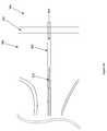
- FIG. 1Adepicts a side view of a catheter structure in accordance with one embodiment of the invention.
- FIG. 1Bdepicts a cross-sectional view of the structure of FIG. 1A .
- FIG. 1Cdepicts a cross-sectional view of a catheter structure in accordance with another embodiment of the invention.
- FIG. 1Ddepicts a side view of a catheter structure in accordance with yet another embodiment of the invention.
- FIG. 1Edepicts a side view of a catheter structure in accordance with still another embodiment of the invention.
- FIG. 1Fdepicts a side view of a catheter structure in accordance with yet another embodiment of the invention.
- FIG. 2depicts a side view of a catheter structure in accordance still another embodiment of the invention.
- FIGS. 3A-3Fare side views depicting various stages of yet another catheter structure embodiment of the invention, including a traversing member traversing a tissue wall in a body.
- FIGS. 3G-3Iare side views of a variation of the embodiment of FIGS. 3A-F , in which sleeve is left positioned after withdrawal of the tissue traversing member to function as an access lumen across the tissue wall.
- FIG. 4is a side view depicting use of a catheter structure embodiment similar to that depicted in FIG. 2 .
- FIGS. 5A-5Ndepict various structures for confirming a position of a traversing member relative to a tissue wall in accordance with various embodiments of the invention.
- FIGS. 6A and 6Bare flow charts illustrating two exemplary procedures for traversing a tissue wall in accordance with embodiments of the invention.
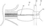
- FIG. 1Aa side view of a distal portion ( 100 ) of a catheter in accordance with the present invention is depicted. The same structure is depicted in cross-sectional view in FIG. 1B .
- a balloon ( 102 )is disposed at the end of an elongate tubular member ( 118 ) which defines various lumens ( 120 , 122 , 124 ) and confines various structures ( 106 , 112 ) associated with balloon-based optical visualization.
- the tubular member ( 126 )extends from the elongate tubular member ( 118 ) to the distal end surface ( 104 ) of the balloon, which in the depicted embodiment is substantially flat with the balloon ( 102 ) in an inflated or expanded configuration ( 128 ).
- the balloon ( 102 )may be inflated with carbon dioxide or another relatively biologically inert gas.
- the tubular member ( 126 )also preferably comprises a substantially translucent polymeric material, such as polymethylmethacrylate (“PMMA”) or polyimide, paired appropriately with the imaging modality, to enable visualization into and across the tubular member ( 126 ) with the imaging element ( 108 ).
- PMMApolymethylmethacrylate
- the tubular membermay comprise a separate tube component coupled to the distal end of the elongate tubular member ( 118 ) utilizing conventional techniques such as polymeric adhesive or stainless steel clips, or may comprise an extension of the material comprising the elongate tubular member ( 118 ).
- the imaging element ( 108 )may comprise a distal end of an optical fiber, in which case the depicted image transmission line ( 106 ) comprises an optical fiber, or it may comprise another image capturing element, such as a charge-coupled-device (CCD) or infrared imaging chip, in which case the image transmission line ( 106 ) may comprise an electronic data transmission wire.
- a lighting element ( 110 )is paired with the imaging element to provide illumination or radiation appropriate for capturing images in the given tissue cavity.
- the lighting element ( 110 )preferably comprises an emitter of light, such as a small light bulb, light emitting diode, or end of another optical fiber distal end in communication with an emitter or light.
- the light energy transmission line ( 112 )may comprise optical fiber, electronic lead wire, or the like to transmit the appropriate lighting energy to the lighting element ( 110 ).
- the lighting element ( 110 )comprises an emitter of infrared-spectrum radiation and the imaging element ( 108 ) comprises an infrared-detecting imaging element to enable infrared-spectrum visualization within the geometrically prescribed field of view ( 114 ).
- Suitable infrared emitters and detectorsare well known in the art and available from suppliers such as CardioOptics of Boulder, Colo.
- the imaging element ( 108 )may comprise a lens, filter, mirror, or other structure configured to control the field of view ( 114 ) or focal length of the associated imaging element ( 108 ). Further, a lens, filter, mirror, or other structure may be positioned distally from the imaging element ( 108 ) within the balloon portion ( 116 ) of the catheter distal end ( 100 ) for similar purposes.
- the utilization of a imaging element ( 108 ) located at the distal end of a medical instrument, such as a balloon catheter, for purposes of visualizing objects from the point of interestis referred to herein as “direct visualization”. In other words, “direct visualization” is used in reference to placing an imaging “eye” distally to the location of tissue treatment interest.
- FIG. 1Ba cross-sectional view of the structures of FIG. 1A depicts the balloon sizing lumens ( 120 , 122 ), working lumen ( 124 ), imaging element ( 108 ), and lighting element ( 110 ) in a substantially aligned configuration which is more resistive to cantilever bending of the catheter distal end ( 100 ) along the direction of the aligned configuration than in a direction 90-degrees rotated from such alignment.
- such componentryis cross-sectionally arranged as tightly as possible about the central axis of the elongate tubular member ( 118 ) to facilitate easier and more uniform cantilever bending.
- Such componentsmay be arranged within the elongate tubular member ( 118 ) to facilitate overall mechanical performance goals given the mechanics of the components themselves. For example, in an embodiment where high cantilever-bending flexibility in all directions is desired, and wherein the image transmission line ( 106 ) and light energy transmission line ( 112 ) comprise relatively stiff optical fiber, it is advantageous to position these two structures ( 106 , 112 ) close to the central axis of the elongate tubular member ( 118 ).
- the elongate tubular member ( 118 )preferably comprises a conventional polymeric material, such as that sold under the trade name “PebaxTM” by Atofina Corporation, which is suitable for use inside of animals and has desirable mechanical and manufacturing properties.
- a conventional polymeric materialsuch as that sold under the trade name “PebaxTM” by Atofina Corporation, which is suitable for use inside of animals and has desirable mechanical and manufacturing properties.
- glass fiberssuch as those conventionally utilized in endoscopes, may be utilized, or more flexible polymeric optical fibers, such as those available from Nanoptics Corporation of Gainesville, Fla., may be utilized.
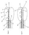
- FIG. 1Ddepicts a structure similar to that of FIG. 1A , with the exception that the balloon ( 102 ) is in a deflated or contracted configuration ( 130 ), as the result of a removal of saline ( 132 ) from the balloon ( 102 ) via the balloon sizing lumens ( 120 , 122 ).
- one of the balloon sizing lumens ( 120 )is reserved only for inflation, while the other ( 122 ) is reserved for deflation. More or less than two balloon sizing lumens may be suitable, depending upon the diameter of such structures and desired rate of inflation and deflation, as would be apparent to one skilled in the art. As shown in FIG.
- the contracted ( 130 ) balloonpreferably has an outer diameter roughly the same size as the associated elongate tubular member ( 118 ) for atraumatic, smooth endolumenal delivery while also facilitating a narrowed forward-looking field of view ( 115 ) with the imaging element ( 108 ) during delivery.
- FIG. 1Eanother embodiment is depicted wherein the imaging element ( 108 ) is positioned forward within the balloon ( 102 ) to gain better access to adjacent objects of interest adjacent the distal end of the balloon ( 102 ) and within the field of view ( 114 ) of the imaging element ( 108 ) and broadcast range of the lighting element ( 110 ).
- the image transmission line ( 106 )extends beyond the distal end of the elongate tubular member ( 118 ) and into the balloon ( 102 ), as depicted in FIG. 1E .
- the portion of the image transmission line ( 106 ) within the balloon ( 102 )may be mechanically stabilized with small polymer or metallic clips ( 134 , 136 ), as shown.
- FIG. 1Fanother embodiment is depicted wherein the lighting element ( 110 ) is positioned forward into the balloon ( 102 ) with the imaging element ( 108 ) to minimize shadowing effects.
- Mechanical stabilizers ( 138 , 140 ) similar to those described in reference to FIG. 1Emay be utilized to maintain the relative positioning of the balloon ( 102 ), tubular member ( 126 ), imaging element ( 108 ), and lighting element ( 110 ).
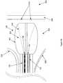
- the balloon ( 102 )comprises a concave surface ( 144 ) distally upon inflation, and wherein the imaging element ( 108 ) and lighting element ( 110 ) are positioned for substantially immediate visualization of adjacently positioned objects.
- Such lumens ( 150 , 152 )are extended through the balloon ( 102 ) to the concave surface ( 144 ) by small tubular members ( 154 , 156 ), which may be stabilized along with the other associated structures within the balloon ( 102 ) utilizing mechanical stabilizers ( 146 , 148 ) similar to those described in reference to FIG. 1E , as shown in FIG. 2 .
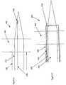
- the distal end of the catheter ( 100 )is positioned in the vicinity of a targeted tissue structure or tissue wall ( 300 ).
- the distal end ( 100 )may be advanced through a relatively tight geometry between two tissue structures ( 306 , 308 ) and into a first enlarged cavity ( 302 ), which may be opposite the targeted tissue wall ( 300 ) from a second enlarged cavity ( 304 ).
- a targeted region of the tissue wall ( 300 )may be identifiable by terrain or substructures ( 310 ) comprising the surface of the targeted tissue wall ( 300 ).
- a narrowed field of view ( 115 ) captured by the imaging element ( 108 ) as facilitated by the lighting element ( 110 )may be utilized for navigating the balloon ( 102 ) into position adjacent the tissue wall ( 300 ).
- the translucent media within the balloon ( 102 )may comprise a contrast agent to facilitate imaging.
- the translucent mediapreferably comprises a conventional contrast agent such as iodine.
- the balloonUpon entry into a relatively large cavity ( 302 ), the balloon may be inflated to provide a broadened field of view and illumination, as shown in FIG. 3B . Positioning of the balloon ( 102 ) relative to the first enlarged cavity ( 302 ) may be confirmed or monitored using conventional techniques, such as ultrasound and fluoroscopy.
- the expanded balloonis advanced into contact with the targeted tissue wall ( 300 ), where even with a nontranslucent cavity ( 302 ) media such as blood, the tissue wall ( 300 ) and substructures thereof ( 310 ) may be visualized through the balloon ( 102 ) with the imaging element ( 108 ) and lighting element ( 110 ). With such visualization, it may be preferable to fine-tune the position of the balloon relative to the tissue wall ( 300 ).
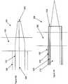
- a tissue traversing membersuch as a trocar or BrockenbroughTM needle, is advanced through the working lumen ( 124 ) of the elongate tubular member ( 118 ) and tubular member ( 126 ) to a position adjacent the targeted tissue wall ( 300 ).
- the tubular member ( 126 )preferably comprises a material through which the imaging element ( 108 ) can “see” to provide the user with feedback regarding the relative positioning of the traversing member ( 312 ), balloon ( 102 ), and tissue wall ( 300 ).
- the traversing member ( 312 )is advanced into and across the tissue wall ( 300 ), as depicted in FIG.
- FIGS. 3EVisualization of gradient markers (not shown) on the traversing member ( 312 ), along with images of the pertinent structures from other modalities, such as fluoroscopy and/or ultrasound, facilitate precise positioning of a portion of the traversing member ( 312 ) across and beyond ( 314 ) the subject tissue wall ( 300 ), into the second cavity ( 304 ). Further details of the traversal positioning and confirmation are described in reference to FIGS. 5A-5N . While the illustrative description in reference FIGS. 3A-3E incorporates a balloon catheter structure similar to that of FIG. 1A , such description is applicable to embodiments such as those depicted in FIGS. 1E and 1F and FIG. 2 , with the exception that the structures similar to FIG. 2 may involve additional steps, as further described in reference to FIG. 4 and FIG. 6B .
- the distal end of the cathetermay be withdrawn, leaving behind the ( 312 ).
- the traversing member ( 312 )is advanced into place accompanied with a preferably tubular sleeve ( 500 ) which may be left in place along with the traversing member ( 312 ) following withdrawal of the catheter.
- the traversing member ( 312 )may subsequently be withdrawn, leaving behind only the sleeve ( 500 ), which provides an access lumen ( 501 ) over to the second cavity ( 304 ), the access lumen being usable as a working lumen for tools, injections, and the like which may be used to examine and treat the second cavity ( 304 ), tissue wall ( 300 ), or other adjacent tissues.
- FIG. 4a depiction of a catheter distal end ( 101 ) similar to that depicted in FIG. 2 is illustrated in a position analogous to the positioning of structures of FIG. 3C to illustrate the notion that a flushing of substantially translucent fluid ( 316 ) may be utilized to facilitate viewing by the imaging element ( 108 ) and lighting element ( 110 ) through a volume ( 318 ) captured between the concave surface ( 144 ) of the depicted embodiment and a tissue wall ( 300 ).
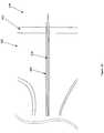
- FIG. 5Aa close-up side view depicting an embodiment of a traversing member ( 312 ) positioned across a tissue wall ( 300 ) is depicted.
- the traversing member ( 312 )is guided to the tissue wall ( 300 ) by the tubular member ( 126 ).
- the distal tip ( 314 ) of the traversing memberis positioned in the cavity ( 304 ) opposite the cavity ( 302 ) in which the tubular member ( 126 ) is positioned.
- FIG. 5Ba close-up side view depicting an embodiment of a traversing member ( 312 ) with a sleeve ( 500 ) is illustrated, with the sleeve ( 500 ) and traversing member ( 312 ) both advanced into a position across the tissue wall with distal protrusion ( 314 ) into the cavity ( 304 ) opposite the cavity in which the tubular member ( 126 ) is positioned.
- FIGS. 5C-5D , 5 E- 5 F, 5 G- 5 H, 5 I- 5 J, 5 K- 5 L, and 5 M- 5 Ndepict pairings of embodiments analogous to the sleeveless and sleeved embodiments depicted in FIGS. 5A and 5B .
- Each of these pairingsfeatures a different embodiment for confirming the position of a traversing member ( 312 ) across a subject tissue wall ( 300 ) by sensing or monitoring a difference known to be associated with a desired second cavity ( 304 ) position or position within the targeted tissue wall ( 300 ).
- localized pressure within a first cavity ( 302 )may be substantially different than both the localized pressure within the tissue wall ( 300 ) and within a second cavity ( 304 ).
- FIGS. 5C-5NFor flow rate, oxygen saturation, etcetera, as described in reference to FIGS. 5C-5N .
- Each of the different monitoring variablesis described separately in FIGS. 5C-5N , but, as would be apparent to one skilled in the art, the monitoring structures and modalities may be combined for increased position determination capability.
- the location of the traversing member ( 312 )may be determined by sampling fluid along a pathway ( 502 ) through a lumen ( 317 ) formed in the traversing member ( 312 ), and transporting sampled fluid proximally to a position outside of the body for conventional testing, such as rapid chemical testing, pulse oximetry, and the like.
- a traversing member ( 312 ) defining such a lumen ( 317 )could be formed using conventional technologies, and purchased from suppliers of high-precision machined trocars and similar structures such as Disposable Instrument Company, Inc. of Shawnee Mission, Kans. FIG.
- 5Ddepicts a sleeved embodiment wherein fluid is sampled along a pathway ( 504 ) between the traversing member ( 312 ) and the sleeve ( 500 ).
- the lumen ( 501 ) of an empty sleeve ( 500 )may serve a similar purpose.
- a traversing member ( 312 ) having a distally disposed pressure sensor ( 508 ) with a sensor lead ( 510 )may be utilized to monitor pressure changes at the distal portion of the traversing member ( 312 ).
- Suitable small pressure sensors ( 508 )are known in the art and available from suppliers such as Motorola Sensor Products of Phoenix, Ariz., and IC Sensors, a division of Measurement Specialties, of Milpitas, Calif.
- FIG. 5Fdepicts an embodiment wherein a pressure sensor ( 508 ) is coupled to a sleeve ( 500 ).
- a color shade sensor ( 512 )is coupled to the distal portion of a traversing member ( 312 ) to facilitate monitoring of the color or graytone of local objects such as aterial versus venous blood.
- the color shade sensor ( 512 )preferably comprises a CCD or CMOS-based image sensor, such as those available from suppliers such as Eastman Kodak Image Sensor Solutions, which is configured in this embodiment to transmit data proximally through a sensor lead ( 514 ) as depicted.
- FIG. 5Hdepicts an embodiment wherein a color shade sensor ( 512 ) is coupled to a sleeve as opposed to directly to the traversing member ( 312 ).
- mirrors, lenses, filters, and the likemay be utilized to enhance or modify the image sampling of such sensors.
- an oxygen saturation sensor ( 516 )is coupled to the distal end of a traversing member ( 312 ) to facilitate monitoring of the partial pressure of oxygen at the oxygen saturation sensor ( 516 ) location utilizing a sensor lead ( 518 ).
- an oxygen saturation sensor ( 516 )may also be positioned upon a sleeve ( 500 ).
- Small oxygen saturation sensorsgenerally comprising a small radiation transmitter, such as a laser diode, and a small radiation receiver, are available from suppliers such as Nellcor Puritan Bennett of Pleasanton, Calif.
- FIG. 5Kan embodiment of a traversing member is depicted with a flow sensor ( 520 ) disposed at the distal tip, in a configuration selected to access flows straight ahead of the advancing traversing member ( 312 ).
- FIG. 5Ldepicts a similar embodiment with a flow sensor coupled to a sleeve ( 500 ).
- flow rate datais transmitted proximally, preferably via a sensor lead ( 522 ).
- Small flow rate sensorsbased upon Doppler ultrasound or laser diode technology are well known in the art and available from suppliers such as Transonic Systems, Inc. of Ithaca, N.Y.
- FIG. 5Man embodiment of a traversing member is depicted with an echo time sensor ( 524 ) disposed at the distal tip, in a configuration selected to access flows straight ahead of the advancing traversing member ( 312 ).
- FIG. 5Ndepicts a similar embodiment with an echo time sensor ( 524 ) coupled to a sleeve ( 500 ).
- echo time datais transmitted proximally, preferably via a sensor lead ( 526 ).
- An echo time sensor ( 524 )generally comprising a radiation emitter and detector configured to detect the proximity of objects in a manner similar to that of sonar technology, may be interfaced with a computer-generated sound signal which changes frequency in accordance with changes in echo time.
- the sound frequency when the echo time sensor ( 524 ) is positioned within a relatively high-density tissue wall ( 300 )may vary significantly from the sound frequency associated with a relatively low density, open cavity ( 304 ), thereby facilitating detection of the distal end of a traversing member ( 312 ) as it is advanced across the tissue wall ( 300 ) and into the adjacent open cavity ( 304 ).
- FIG. 6Aan embodiment of a tissue wall traversal process in accordance with the present invention is summarized in flowchart format.
- a balloon structureis positioned adjacent a tissue wall ( 530 ). Inflation of the balloon optimizes visualization by providing a relatively unobstructed field of view ( 532 ). Subsequent to confirming an appropriate position upon the tissue wall or navigating to an appropriate position utilizing visualization feedback ( 534 ), the traversing member is advanced across the tissue wall while the position is monitored for confirmation of appropriate positioning ( 538 ). With the traversing member appropriately positioned across the tissue wall, the balloon is deflated and retracted proximally to leave the transecting member in place across the tissue wall ( 540 ).
- FIG. 6Banother embodiment of a tissue wall traversal process in accordance with the present invention is summarized in flowchart format, the embodiment of FIG. 6B differing from that of FIG. 6A in that the embodiment of FIG. 6B comprises an additional step of flushing a volume entrapped between a concave balloon surface to provide better translucency for image capture, in a process wherein a structure similar to that described in reference to FIGS. 2 and 4 is utilized.
- tissue structures 306 and 308may represent portions of the wall of a right atrium cavity ( 302 ), the tissue wall ( 300 ) may represent the atrial septum, and the second cavity ( 304 ) may represent the left atrium of the heart.
- the collapsed catheter distal end ( 100 )may be advanced toward the atrial septum, guided into position by wall ( 300 ) terrain ( 310 ) such as the outline of the fossa ovalis.
- Appropriate positioning of the working lumen ( 124 ) relative to the outlines of the fossa ovalismay be confirmed utilizing images from the imaging element ( 108 ) with a preferably fully expanded ( 128 ) balloon ( 102 ) urged against the atrial septum, subsequent to which a traversing member ( 312 ), such as a BrockenbroughTM needle, may be advanced into the atrial septal wall through the working lumen ( 124 ), as observed through the tubular member ( 126 ), and preferably also through redundant visualization modalities, such as ultrasound and/or fluoroscopy.
- a traversing member ( 312 )such as a BrockenbroughTM needle
- the traversing member ( 312 )may be instrumented with a sensor, such as a pressure, flow rate, color shade, or other sensor, to confirm that the distal tip of the traversing member ( 312 ) is indeed where the operator thinks it is.
- a sensorsuch as a pressure, flow rate, color shade, or other sensor
Landscapes
- Health & Medical Sciences (AREA)
- Life Sciences & Earth Sciences (AREA)
- Surgery (AREA)
- Medical Informatics (AREA)
- Biophysics (AREA)
- Engineering & Computer Science (AREA)
- Biomedical Technology (AREA)
- Heart & Thoracic Surgery (AREA)
- Physics & Mathematics (AREA)
- Molecular Biology (AREA)
- Pathology (AREA)
- Animal Behavior & Ethology (AREA)
- General Health & Medical Sciences (AREA)
- Public Health (AREA)
- Veterinary Medicine (AREA)
- Nuclear Medicine, Radiotherapy & Molecular Imaging (AREA)
- Optics & Photonics (AREA)
- Radiology & Medical Imaging (AREA)
- Endoscopes (AREA)
Abstract
Description
Claims (23)
Priority Applications (2)
| Application Number | Priority Date | Filing Date | Title |
|---|---|---|---|
| US10/949,032US8172747B2 (en) | 2003-09-25 | 2004-09-24 | Balloon visualization for traversing a tissue wall |
| US13/452,029US20120296161A1 (en) | 2003-09-25 | 2012-04-20 | Balloon visualization for traversing a tissue wall |
Applications Claiming Priority (2)
| Application Number | Priority Date | Filing Date | Title |
|---|---|---|---|
| US50629303P | 2003-09-25 | 2003-09-25 | |
| US10/949,032US8172747B2 (en) | 2003-09-25 | 2004-09-24 | Balloon visualization for traversing a tissue wall |
Related Child Applications (1)
| Application Number | Title | Priority Date | Filing Date |
|---|---|---|---|
| US13/452,029ContinuationUS20120296161A1 (en) | 2003-09-25 | 2012-04-20 | Balloon visualization for traversing a tissue wall |
Publications (2)
| Publication Number | Publication Date |
|---|---|
| US20050197530A1 US20050197530A1 (en) | 2005-09-08 |
| US8172747B2true US8172747B2 (en) | 2012-05-08 |
Family
ID=34915470
Family Applications (2)
| Application Number | Title | Priority Date | Filing Date |
|---|---|---|---|
| US10/949,032Active2026-03-05US8172747B2 (en) | 2003-09-25 | 2004-09-24 | Balloon visualization for traversing a tissue wall |
| US13/452,029AbandonedUS20120296161A1 (en) | 2003-09-25 | 2012-04-20 | Balloon visualization for traversing a tissue wall |
Family Applications After (1)
| Application Number | Title | Priority Date | Filing Date |
|---|---|---|---|
| US13/452,029AbandonedUS20120296161A1 (en) | 2003-09-25 | 2012-04-20 | Balloon visualization for traversing a tissue wall |
Country Status (1)
| Country | Link |
|---|---|
| US (2) | US8172747B2 (en) |
Cited By (28)
| Publication number | Priority date | Publication date | Assignee | Title |
|---|---|---|---|---|
| US20110319910A1 (en)* | 2007-08-14 | 2011-12-29 | Hansen Medical, Inc. | Methods and devices for controlling a shapeable instrument |
| US20150196345A1 (en)* | 2013-11-01 | 2015-07-16 | C2 Therapeutics, Inc. | Cryogenic balloon ablation system |
| US9333031B2 (en) | 2013-04-08 | 2016-05-10 | Apama Medical, Inc. | Visualization inside an expandable medical device |
| US9610006B2 (en) | 2008-11-11 | 2017-04-04 | Shifamed Holdings, Llc | Minimally invasive visualization systems |
| WO2017083785A1 (en)* | 2015-11-13 | 2017-05-18 | Boston Scientific Scimed, Inc. | Direct visualization devices, systems, and methods for transseptal crossing |
| US9655677B2 (en) | 2010-05-12 | 2017-05-23 | Shifamed Holdings, Llc | Ablation catheters including a balloon and electrodes |
| US9795442B2 (en) | 2008-11-11 | 2017-10-24 | Shifamed Holdings, Llc | Ablation catheters |
| US10098694B2 (en) | 2013-04-08 | 2018-10-16 | Apama Medical, Inc. | Tissue ablation and monitoring thereof |
| US10098686B2 (en) | 2015-05-15 | 2018-10-16 | Pentax Of America, Inc. | Cryogenic balloon ablation system |
| US10159533B2 (en) | 2014-07-01 | 2018-12-25 | Auris Health, Inc. | Surgical system with configurable rail-mounted mechanical arms |
| US10251693B2 (en) | 2016-05-20 | 2019-04-09 | Pentax Of America, Inc. | Cryogenic ablation system with rotatable and translatable catheter |
| US10350390B2 (en) | 2011-01-20 | 2019-07-16 | Auris Health, Inc. | System and method for endoluminal and translumenal therapy |
| US10349824B2 (en) | 2013-04-08 | 2019-07-16 | Apama Medical, Inc. | Tissue mapping and visualization systems |
| US10368951B2 (en) | 2005-03-04 | 2019-08-06 | Auris Health, Inc. | Robotic catheter system and methods |
| US10383676B2 (en) | 2008-11-21 | 2019-08-20 | Pentax Of America, Inc. | Cryogenic ablation system and method |
| US10500001B2 (en) | 2015-05-15 | 2019-12-10 | Auris Health, Inc. | Surgical robotics system |
| US10667871B2 (en) | 2014-09-30 | 2020-06-02 | Auris Health, Inc. | Configurable robotic surgical system with virtual rail and flexible endoscope |
| US10702348B2 (en) | 2015-04-09 | 2020-07-07 | Auris Health, Inc. | Surgical system with configurable rail-mounted mechanical arms |
| US10736693B2 (en) | 2015-11-16 | 2020-08-11 | Apama Medical, Inc. | Energy delivery devices |
| US10751140B2 (en) | 2018-06-07 | 2020-08-25 | Auris Health, Inc. | Robotic medical systems with high force instruments |
| US10874468B2 (en) | 2004-03-05 | 2020-12-29 | Auris Health, Inc. | Robotic catheter system |
| US11020016B2 (en) | 2013-05-30 | 2021-06-01 | Auris Health, Inc. | System and method for displaying anatomy and devices on a movable display |
| US11497898B2 (en) | 2016-04-19 | 2022-11-15 | Boston Scientific Scimed, Inc. | Weeping balloon devices |
| US11723518B2 (en)* | 2017-10-25 | 2023-08-15 | Boston Scientific Scimed, Inc. | Direct visualization catheter and system |
| US11730515B2 (en) | 2010-04-23 | 2023-08-22 | Mark D. Wieczorek, PC | Transseptal access device and method of use |
| US11744670B2 (en) | 2018-01-17 | 2023-09-05 | Auris Health, Inc. | Surgical platform with adjustable arm supports |
| US11826020B2 (en) | 2015-01-23 | 2023-11-28 | Boston Scientific Scimed, Inc. | Balloon catheter suturing systems, methods, and devices having pledgets |
| US12082775B2 (en) | 2015-12-18 | 2024-09-10 | Boston Scientific Scimed, Inc. | Radially-directed balloon visualization device |
Families Citing this family (164)
| Publication number | Priority date | Publication date | Assignee | Title |
|---|---|---|---|---|
| US7231243B2 (en) | 2000-10-30 | 2007-06-12 | The General Hospital Corporation | Optical methods for tissue analysis |
| WO2002088684A1 (en) | 2001-04-30 | 2002-11-07 | The General Hospital Corporation | Method and apparatus for improving image clarity and sensitivity in optical coherence tomography using dynamic feedback to control focal properties and coherence gating |
| US8956280B2 (en) | 2002-05-30 | 2015-02-17 | Intuitive Surgical Operations, Inc. | Apparatus and methods for placing leads using direct visualization |
| EP1426411A1 (en)* | 2002-12-06 | 2004-06-09 | KRATON Polymers Research B.V. | Styrenic block copolymer compositions to be used for the manufacture of transparent, gel free films |
| EP2436307B1 (en) | 2003-03-31 | 2015-10-21 | The General Hospital Corporation | Speckle reduction in optical coherence tomography by path length encoded angular compounding |
| KR101386971B1 (en) | 2003-06-06 | 2014-04-18 | 더 제너럴 하스피탈 코포레이션 | Process and apparatus for a wavelength tunning source |
| US8172747B2 (en) | 2003-09-25 | 2012-05-08 | Hansen Medical, Inc. | Balloon visualization for traversing a tissue wall |
| US20050113719A1 (en)* | 2003-09-26 | 2005-05-26 | Vahid Saadat | Left atrial access apparatus and methods |
| US20110270034A1 (en)* | 2004-02-10 | 2011-11-03 | Mackin Robert A | Endotracheal tube with side mounted camera and illuminator |
| US20050228452A1 (en)* | 2004-02-11 | 2005-10-13 | Mourlas Nicholas J | Steerable catheters and methods for using them |
| US8528565B2 (en) | 2004-05-28 | 2013-09-10 | St. Jude Medical, Atrial Fibrillation Division, Inc. | Robotic surgical system and method for automated therapy delivery |
| US10863945B2 (en) | 2004-05-28 | 2020-12-15 | St. Jude Medical, Atrial Fibrillation Division, Inc. | Robotic surgical system with contact sensing feature |
| US9782130B2 (en) | 2004-05-28 | 2017-10-10 | St. Jude Medical, Atrial Fibrillation Division, Inc. | Robotic surgical system |
| US7974674B2 (en) | 2004-05-28 | 2011-07-05 | St. Jude Medical, Atrial Fibrillation Division, Inc. | Robotic surgical system and method for surface modeling |
| US10258285B2 (en) | 2004-05-28 | 2019-04-16 | St. Jude Medical, Atrial Fibrillation Division, Inc. | Robotic surgical system and method for automated creation of ablation lesions |
| US7632265B2 (en) | 2004-05-28 | 2009-12-15 | St. Jude Medical, Atrial Fibrillation Division, Inc. | Radio frequency ablation servo catheter and method |
| US8755864B2 (en) | 2004-05-28 | 2014-06-17 | St. Jude Medical, Atrial Fibrillation Division, Inc. | Robotic surgical system and method for diagnostic data mapping |
| AU2005270037B2 (en) | 2004-07-02 | 2012-02-09 | The General Hospital Corporation | Endoscopic imaging probe comprising dual clad fibre |
| EP2272421A1 (en) | 2004-08-24 | 2011-01-12 | The General Hospital Corporation | Method and apparatus for imaging of vessel segments |
| WO2006024014A2 (en) | 2004-08-24 | 2006-03-02 | The General Hospital Corporation | Process, system and software arrangement for measuring a mechanical strain and elastic properties of a sample |
| WO2006058346A1 (en) | 2004-11-29 | 2006-06-01 | The General Hospital Corporation | Arrangements, devices, endoscopes, catheters and methods for performing optical imaging by simultaneously illuminating and detecting multiple points on a sample |
| US8050746B2 (en) | 2005-02-02 | 2011-11-01 | Voyage Medical, Inc. | Tissue visualization device and method variations |
| US10064540B2 (en) | 2005-02-02 | 2018-09-04 | Intuitive Surgical Operations, Inc. | Visualization apparatus for transseptal access |
| US7930016B1 (en) | 2005-02-02 | 2011-04-19 | Voyage Medical, Inc. | Tissue closure system |
| US9510732B2 (en) | 2005-10-25 | 2016-12-06 | Intuitive Surgical Operations, Inc. | Methods and apparatus for efficient purging |
| US7860556B2 (en) | 2005-02-02 | 2010-12-28 | Voyage Medical, Inc. | Tissue imaging and extraction systems |
| US8078266B2 (en) | 2005-10-25 | 2011-12-13 | Voyage Medical, Inc. | Flow reduction hood systems |
| US20080015569A1 (en) | 2005-02-02 | 2008-01-17 | Voyage Medical, Inc. | Methods and apparatus for treatment of atrial fibrillation |
| US7918787B2 (en)* | 2005-02-02 | 2011-04-05 | Voyage Medical, Inc. | Tissue visualization and manipulation systems |
| US7860555B2 (en) | 2005-02-02 | 2010-12-28 | Voyage Medical, Inc. | Tissue visualization and manipulation system |
| US8137333B2 (en) | 2005-10-25 | 2012-03-20 | Voyage Medical, Inc. | Delivery of biological compounds to ischemic and/or infarcted tissue |
| US11478152B2 (en) | 2005-02-02 | 2022-10-25 | Intuitive Surgical Operations, Inc. | Electrophysiology mapping and visualization system |
| ES2337497T3 (en) | 2005-04-28 | 2010-04-26 | The General Hospital Corporation | EVALUATION OF CHARACTERISTICS OF THE IMAGE OF AN ANATOMICAL STRUCTURE IN IMAGES OF TOMOGRAPHY OF OPTICAL COHERENCE. |
| US8155910B2 (en) | 2005-05-27 | 2012-04-10 | St. Jude Medical, Atrial Fibrillation Divison, Inc. | Robotically controlled catheter and method of its calibration |
| US9060689B2 (en) | 2005-06-01 | 2015-06-23 | The General Hospital Corporation | Apparatus, method and system for performing phase-resolved optical frequency domain imaging |
| US7553278B2 (en)* | 2005-06-01 | 2009-06-30 | Cannuflow, Inc. | Protective cap for arthroscopic instruments |
| EP2267404B1 (en) | 2005-08-09 | 2016-10-05 | The General Hospital Corporation | Apparatus and method for performing polarization-based quadrature demodulation in optical coherence tomography |
| US7843572B2 (en) | 2005-09-29 | 2010-11-30 | The General Hospital Corporation | Method and apparatus for optical imaging via spectral encoding |
| US8221310B2 (en) | 2005-10-25 | 2012-07-17 | Voyage Medical, Inc. | Tissue visualization device and method variations |
| DK1973466T3 (en) | 2006-01-19 | 2021-02-01 | Massachusetts Gen Hospital | BALLOON IMAGING CATHETER |
| US8145018B2 (en) | 2006-01-19 | 2012-03-27 | The General Hospital Corporation | Apparatus for obtaining information for a structure using spectrally-encoded endoscopy techniques and methods for producing one or more optical arrangements |
| JP5680829B2 (en) | 2006-02-01 | 2015-03-04 | ザ ジェネラル ホスピタル コーポレイション | A device that irradiates a sample with multiple electromagnetic radiations |
| WO2007149602A2 (en) | 2006-02-01 | 2007-12-27 | The General Hospital Corporation | Methods and systems for providing electromagnetic radiation to at least one portion of a sample using conformal laser therapy procedures |
| EP2982929A1 (en) | 2006-02-24 | 2016-02-10 | The General Hospital Corporation | Methods and systems for performing angle-resolved fourier-domain optical coherence tomography |
| WO2007133961A2 (en) | 2006-05-10 | 2007-11-22 | The General Hospital Corporation | Processes, arrangements and systems for providing frequency domain imaging of a sample |
| JP2007319396A (en) | 2006-05-31 | 2007-12-13 | Olympus Medical Systems Corp | Endoscope and endoscope system |
| IL176046A (en)* | 2006-05-31 | 2010-06-30 | Wave Group Ltd | Abdominal observation device |
| US9055906B2 (en) | 2006-06-14 | 2015-06-16 | Intuitive Surgical Operations, Inc. | In-vivo visualization systems |
| JP2009539575A (en)* | 2006-06-14 | 2009-11-19 | ボエッジ メディカル, インコーポレイテッド | Visualization apparatus and method for transseptal access |
| US20080097476A1 (en) | 2006-09-01 | 2008-04-24 | Voyage Medical, Inc. | Precision control systems for tissue visualization and manipulation assemblies |
| US10004388B2 (en) | 2006-09-01 | 2018-06-26 | Intuitive Surgical Operations, Inc. | Coronary sinus cannulation |
| WO2008028149A2 (en) | 2006-09-01 | 2008-03-06 | Voyage Medical, Inc. | Electrophysiology mapping and visualization system |
| JPWO2008041755A1 (en)* | 2006-10-04 | 2010-02-04 | 東京電力株式会社 | AC / DC converter |
| US8838213B2 (en)* | 2006-10-19 | 2014-09-16 | The General Hospital Corporation | Apparatus and method for obtaining and providing imaging information associated with at least one portion of a sample, and effecting such portion(s) |
| US10335131B2 (en) | 2006-10-23 | 2019-07-02 | Intuitive Surgical Operations, Inc. | Methods for preventing tissue migration |
| US20080183036A1 (en) | 2006-12-18 | 2008-07-31 | Voyage Medical, Inc. | Systems and methods for unobstructed visualization and ablation |
| US9226648B2 (en) | 2006-12-21 | 2016-01-05 | Intuitive Surgical Operations, Inc. | Off-axis visualization systems |
| US8131350B2 (en) | 2006-12-21 | 2012-03-06 | Voyage Medical, Inc. | Stabilization of visualization catheters |
| US8108069B2 (en)* | 2007-01-10 | 2012-01-31 | Hansen Medical, Inc. | Robotic catheter system and methods |
| US20090036900A1 (en)* | 2007-02-02 | 2009-02-05 | Hansen Medical, Inc. | Surgery methods using a robotic instrument system |
| US9176319B2 (en) | 2007-03-23 | 2015-11-03 | The General Hospital Corporation | Methods, arrangements and apparatus for utilizing a wavelength-swept laser using angular scanning and dispersion procedures |
| WO2008118481A2 (en) | 2007-03-26 | 2008-10-02 | Hansen Medical, Inc. | Robotic catheter systems and methods |
| US10534129B2 (en) | 2007-03-30 | 2020-01-14 | The General Hospital Corporation | System and method providing intracoronary laser speckle imaging for the detection of vulnerable plaque |
| WO2008131303A2 (en) | 2007-04-20 | 2008-10-30 | Hansen Medical, Inc. | Optical fiber shape sensing systems |
| WO2008133956A2 (en)* | 2007-04-23 | 2008-11-06 | Hansen Medical, Inc. | Robotic instrument control system |
| EP2148608A4 (en) | 2007-04-27 | 2010-04-28 | Voyage Medical Inc | Complex shape steerable tissue visualization and manipulation catheter |
| US20090138025A1 (en)* | 2007-05-04 | 2009-05-28 | Hansen Medical, Inc. | Apparatus systems and methods for forming a working platform of a robotic instrument system by manipulation of components having controllably rigidity |
| US8657805B2 (en) | 2007-05-08 | 2014-02-25 | Intuitive Surgical Operations, Inc. | Complex shape steerable tissue visualization and manipulation catheter |
| WO2008141238A1 (en)* | 2007-05-11 | 2008-11-20 | Voyage Medical, Inc. | Visual electrode ablation systems |
| US8409234B2 (en)* | 2007-05-25 | 2013-04-02 | Hansen Medical, Inc. | Rotational apparatus system and method for a robotic instrument system |
| US9375158B2 (en) | 2007-07-31 | 2016-06-28 | The General Hospital Corporation | Systems and methods for providing beam scan patterns for high speed doppler optical frequency domain imaging |
| EP2626030A3 (en) | 2007-08-14 | 2017-03-08 | Koninklijke Philips N.V. | Robotic instrument systems and methods utilizing optical fiber sensors |
| US8235985B2 (en) | 2007-08-31 | 2012-08-07 | Voyage Medical, Inc. | Visualization and ablation system variations |
| US8858609B2 (en)* | 2008-02-07 | 2014-10-14 | Intuitive Surgical Operations, Inc. | Stent delivery under direct visualization |
| US20090228020A1 (en)* | 2008-03-06 | 2009-09-10 | Hansen Medical, Inc. | In-situ graft fenestration |
| US20090254083A1 (en)* | 2008-03-10 | 2009-10-08 | Hansen Medical, Inc. | Robotic ablation catheter |
| EP2274572A4 (en) | 2008-05-07 | 2013-08-28 | Gen Hospital Corp | SYSTEM, METHOD AND COMPUTER MEDIUM FOR MONITORING THE MOVEMENT OF VESSELS DURING A THREE-DIMENSIONAL MICROSCOPY EXAMINATION OF CORONARY ARTERIES |
| US9101735B2 (en) | 2008-07-07 | 2015-08-11 | Intuitive Surgical Operations, Inc. | Catheter control systems |
| WO2010009136A2 (en) | 2008-07-14 | 2010-01-21 | The General Hospital Corporation | Apparatus and methods for color endoscopy |
| US8290571B2 (en)* | 2008-08-01 | 2012-10-16 | Koninklijke Philips Electronics N.V. | Auxiliary cavity localization |
| US20100094167A1 (en)* | 2008-10-09 | 2010-04-15 | Jay Iinuma | Medical examining device with fiber optic receiving channel and sampling channel |
| US20100094082A1 (en)* | 2008-10-09 | 2010-04-15 | Jay Iinuma | Medical examining device with an angularly offset fiber optic channel |
| US8894643B2 (en) | 2008-10-10 | 2014-11-25 | Intuitive Surgical Operations, Inc. | Integral electrode placement and connection systems |
| US8333012B2 (en) | 2008-10-10 | 2012-12-18 | Voyage Medical, Inc. | Method of forming electrode placement and connection systems |
| US9468364B2 (en) | 2008-11-14 | 2016-10-18 | Intuitive Surgical Operations, Inc. | Intravascular catheter with hood and image processing systems |
| JP5731394B2 (en) | 2008-12-10 | 2015-06-10 | ザ ジェネラル ホスピタル コーポレイション | System, apparatus and method for extending imaging depth range of optical coherence tomography through optical subsampling |
| JP2012515576A (en) | 2009-01-20 | 2012-07-12 | ザ ジェネラル ホスピタル コーポレイション | Endoscopic biopsy device, system, and method |
| CA2749670A1 (en) | 2009-02-04 | 2010-08-12 | The General Hospital Corporation | Apparatus and method for utilization of a high-speed optical wavelength tuning source |
| JP5819823B2 (en) | 2009-07-14 | 2015-11-24 | ザ ジェネラル ホスピタル コーポレイション | Device for measuring the flow and pressure inside a blood vessel and method of operating the device |
| US8780339B2 (en) | 2009-07-15 | 2014-07-15 | Koninklijke Philips N.V. | Fiber shape sensing systems and methods |
| EP2485643B1 (en) | 2009-10-09 | 2020-02-26 | Flip Technologies Limited | A device for facilitating monitoring the cross-section of a gastric sleeve during formation thereof |
| US8694071B2 (en) | 2010-02-12 | 2014-04-08 | Intuitive Surgical Operations, Inc. | Image stabilization techniques and methods |
| KR20130004326A (en) | 2010-03-05 | 2013-01-09 | 더 제너럴 하스피탈 코포레이션 | Systems, methods and computer-accessible medium which provide microscopic images of at least one anatomical structure at a particular resolution |
| US9814522B2 (en) | 2010-04-06 | 2017-11-14 | Intuitive Surgical Operations, Inc. | Apparatus and methods for ablation efficacy |
| US9069130B2 (en) | 2010-05-03 | 2015-06-30 | The General Hospital Corporation | Apparatus, method and system for generating optical radiation from biological gain media |
| EP2575598A2 (en) | 2010-05-25 | 2013-04-10 | The General Hospital Corporation | Apparatus, systems, methods and computer-accessible medium for spectral analysis of optical coherence tomography images |
| EP2575597B1 (en) | 2010-05-25 | 2022-05-04 | The General Hospital Corporation | Apparatus for providing optical imaging of structures and compositions |
| JP6066901B2 (en) | 2010-06-03 | 2017-01-25 | ザ ジェネラル ホスピタル コーポレイション | Method for apparatus and device for imaging structures in or in one or more luminal organs |
| JP2014501053A (en)* | 2010-10-12 | 2014-01-16 | コーニンクレッカ フィリップス エヌ ヴェ | Wire-type waveguide for terahertz radiation |
| WO2012058381A2 (en) | 2010-10-27 | 2012-05-03 | The General Hospital Corporation | Apparatus, systems and methods for measuring blood pressure within at least one vessel |
| EP4000497A1 (en) | 2011-02-16 | 2022-05-25 | The General Hospital Corporation | Optical coupler for an endoscope |
| US9330092B2 (en) | 2011-07-19 | 2016-05-03 | The General Hospital Corporation | Systems, methods, apparatus and computer-accessible-medium for providing polarization-mode dispersion compensation in optical coherence tomography |
| US20130030363A1 (en) | 2011-07-29 | 2013-01-31 | Hansen Medical, Inc. | Systems and methods utilizing shape sensing fibers |
| US9014789B2 (en) | 2011-09-22 | 2015-04-21 | The George Washington University | Systems and methods for visualizing ablated tissue |
| AU2012312066C1 (en) | 2011-09-22 | 2016-06-16 | 460Medical, Inc. | Systems and methods for visualizing ablated tissue |
| JP2015502562A (en) | 2011-10-18 | 2015-01-22 | ザ ジェネラル ホスピタル コーポレイション | Apparatus and method for generating and / or providing recirculating optical delay |
| WO2013148306A1 (en) | 2012-03-30 | 2013-10-03 | The General Hospital Corporation | Imaging system, method and distal attachment for multidirectional field of view endoscopy |
| JP2015517387A (en) | 2012-05-21 | 2015-06-22 | ザ ジェネラル ホスピタル コーポレイション | Apparatus, device and method for capsule microscopy |
| WO2013179217A1 (en)* | 2012-05-29 | 2013-12-05 | Alvimedica Tibbi̇ Ürünler San. Ve Diş Ti̇c. A.Ş. | A balloon dilatation catheter for treatment of paranasal sinus diseases |
| JP6227652B2 (en) | 2012-08-22 | 2017-11-08 | ザ ジェネラル ホスピタル コーポレイション | System, method, and computer-accessible medium for fabricating a miniature endoscope using soft lithography |
| US9451875B2 (en)* | 2012-12-07 | 2016-09-27 | Cook Medical Technologies Llc | Flexible lens |
| US9968261B2 (en) | 2013-01-28 | 2018-05-15 | The General Hospital Corporation | Apparatus and method for providing diffuse spectroscopy co-registered with optical frequency domain imaging |
| WO2014120791A1 (en) | 2013-01-29 | 2014-08-07 | The General Hospital Corporation | Apparatus, systems and methods for providing information regarding the aortic valve |
| US11179028B2 (en) | 2013-02-01 | 2021-11-23 | The General Hospital Corporation | Objective lens arrangement for confocal endomicroscopy |
| US10342498B2 (en)* | 2013-02-21 | 2019-07-09 | Medtronic Holding Company Sàrl | Cannula with image markers to indicate expandable device size |
| US9566414B2 (en) | 2013-03-13 | 2017-02-14 | Hansen Medical, Inc. | Integrated catheter and guide wire controller |
| US11213363B2 (en) | 2013-03-14 | 2022-01-04 | Auris Health, Inc. | Catheter tension sensing |
| US9498601B2 (en) | 2013-03-14 | 2016-11-22 | Hansen Medical, Inc. | Catheter tension sensing |
| US10478072B2 (en) | 2013-03-15 | 2019-11-19 | The General Hospital Corporation | Methods and system for characterizing an object |
| US9283046B2 (en) | 2013-03-15 | 2016-03-15 | Hansen Medical, Inc. | User interface for active drive apparatus with finite range of motion |
| US10849702B2 (en) | 2013-03-15 | 2020-12-01 | Auris Health, Inc. | User input devices for controlling manipulation of guidewires and catheters |
| EP2997354A4 (en) | 2013-05-13 | 2017-01-18 | The General Hospital Corporation | Detecting self-interefering fluorescence phase and amplitude |
| EP3021735A4 (en) | 2013-07-19 | 2017-04-19 | The General Hospital Corporation | Determining eye motion by imaging retina. with feedback |
| WO2015009932A1 (en) | 2013-07-19 | 2015-01-22 | The General Hospital Corporation | Imaging apparatus and method which utilizes multidirectional field of view endoscopy |
| CN105407786B (en)* | 2013-07-22 | 2018-11-23 | 伍恩迪吉股份有限公司 | Medical apparatus and the method for using the medical apparatus |
| WO2015013651A2 (en) | 2013-07-26 | 2015-01-29 | The General Hospital Corporation | System, apparatus and method utilizing optical dispersion for fourier-domain optical coherence tomography |
| WO2015035354A1 (en) | 2013-09-09 | 2015-03-12 | The Cleveland Clinic Foundation | Endoscope for tissue dissection and visualization |
| EP3068280B1 (en)* | 2013-11-14 | 2021-06-02 | Clph, Llc | Apparatus and systems for epicardial imaging and injection |
| JP6737705B2 (en) | 2013-11-14 | 2020-08-12 | ザ・ジョージ・ワシントン・ユニバーシティThe George Washingtonuniversity | Method of operating system for determining depth of injury site and system for generating images of heart tissue |
| JP2017500550A (en) | 2013-11-20 | 2017-01-05 | ザ・ジョージ・ワシントン・ユニバーシティThe George Washingtonuniversity | System and method for hyperspectral analysis of cardiac tissue |
| WO2015105870A1 (en) | 2014-01-08 | 2015-07-16 | The General Hospital Corporation | Method and apparatus for microscopic imaging |
| US10736494B2 (en) | 2014-01-31 | 2020-08-11 | The General Hospital Corporation | System and method for facilitating manual and/or automatic volumetric imaging with real-time tension or force feedback using a tethered imaging device |
| EP3243476B1 (en) | 2014-03-24 | 2019-11-06 | Auris Health, Inc. | Systems and devices for catheter driving instinctiveness |
| WO2015153982A1 (en) | 2014-04-04 | 2015-10-08 | The General Hospital Corporation | Apparatus and method for controlling propagation and/or transmission of electromagnetic radiation in flexible waveguide(s) |
| US10912462B2 (en) | 2014-07-25 | 2021-02-09 | The General Hospital Corporation | Apparatus, devices and methods for in vivo imaging and diagnosis |
| US9459442B2 (en) | 2014-09-23 | 2016-10-04 | Scott Miller | Optical coupler for optical imaging visualization device |
| KR102499045B1 (en) | 2014-11-03 | 2023-02-10 | 더 조지 워싱턴 유니버시티 | Systems and methods for lesion assessment |
| EP3215001A4 (en) | 2014-11-03 | 2018-04-04 | Luxcath, LLC | Systems and methods for assessment of contact quality |
| EP3223735A4 (en)* | 2014-11-25 | 2018-07-11 | Luxcath, LLC | Visualization catheters |
| US10548467B2 (en) | 2015-06-02 | 2020-02-04 | GI Scientific, LLC | Conductive optical element |
| US20160367120A1 (en) | 2015-06-19 | 2016-12-22 | Children's Medical Center Corporation | Optically Guided Surgical Devices |
| US10779904B2 (en) | 2015-07-19 | 2020-09-22 | 460Medical, Inc. | Systems and methods for lesion formation and assessment |
| WO2017015480A1 (en) | 2015-07-21 | 2017-01-26 | GI Scientific, LLC | Endoscope accessory with angularly adjustable exit portal |
| CA3014320A1 (en)* | 2016-02-12 | 2017-08-17 | Children's Medical Center Corporation | Instrument port with integrated imaging system |
| US11037464B2 (en) | 2016-07-21 | 2021-06-15 | Auris Health, Inc. | System with emulator movement tracking for controlling medical devices |
| US11660121B2 (en) | 2016-10-18 | 2023-05-30 | East End Medical Llc | Transseptal insertion device |
| CA2957977C (en)* | 2017-02-15 | 2019-03-26 | Synaptive Medical (Barbados) Inc. | Sensored surgical tool and surgical intraoperative tracking and imaging system incorporating same |
| WO2019113391A1 (en) | 2017-12-08 | 2019-06-13 | Auris Health, Inc. | System and method for medical instrument navigation and targeting |
| US11324555B2 (en) | 2018-03-09 | 2022-05-10 | The Children's Medical Center Corporation | Instrument port including optical bulb secured to port body |
| US11284788B2 (en) | 2018-03-09 | 2022-03-29 | The Children's Medical Center Corporation | Instrument port with fluid flush system |
| US11213316B2 (en) | 2018-03-09 | 2022-01-04 | The Children's Medical Center Corporation | Gasket with multi-leaflet valve for surgical port apparatus |
| US11547276B2 (en) | 2018-03-09 | 2023-01-10 | The Children's Medical Center Corporation | Optical bulb for surgical instrument port |
| US11179213B2 (en) | 2018-05-18 | 2021-11-23 | Auris Health, Inc. | Controllers for robotically-enabled teleoperated systems |
| US20230248434A1 (en)* | 2019-01-18 | 2023-08-10 | Ipg Photonics Corporation | Efficient multi-functional endoscopic instrument |
| CA3141251A1 (en) | 2019-06-11 | 2020-12-17 | East End Medical, Llc | Directional balloon transseptal insertion device for medical procedures with improved transseptal puncture system with puncture member balloon seal |
| WO2020264418A1 (en) | 2019-06-28 | 2020-12-30 | Auris Health, Inc. | Console overlay and methods of using same |
| EP4017337A4 (en)* | 2019-08-20 | 2023-08-09 | Fertigo Medical Ltd. | An imaging device with an inflatable cover |
| AU2020349508A1 (en)* | 2019-09-20 | 2022-04-14 | East End Medical, Llc | Directional balloon transseptal insertion device for medical procedures with improved transseptal puncture system with puncture member balloon seal |
| AU2020357991A1 (en) | 2019-10-04 | 2022-04-21 | East End Medical, Llc | Directional balloon transseptal insertion device for medical procedures with improved handle |
| EP4087511A4 (en) | 2020-01-08 | 2024-02-14 | 460Medical, Inc. | Systems and methods for optical interrogation of ablation lesions |
| AU2021221979A1 (en) | 2020-02-18 | 2022-09-15 | East End Medical, Llc | Deflectable anchor balloon catheter for vascular procedures |
| WO2021207229A1 (en)* | 2020-04-08 | 2021-10-14 | Boston Scientific Scimed, Inc. | Medical instrument having a balloon and an extraction member |
| WO2022061059A1 (en)* | 2020-09-17 | 2022-03-24 | Shifamed Holdings, Llc | Tissue piercing assemblies and methods of use |
| CN114366250B (en)* | 2021-12-31 | 2023-09-05 | 杭州德柯医疗科技有限公司 | Sleeves, injection devices, injection systems, ablation devices and ablation systems |
Citations (17)
| Publication number | Priority date | Publication date | Assignee | Title |
|---|---|---|---|---|
| US4961738A (en) | 1987-01-28 | 1990-10-09 | Mackin Robert A | Angioplasty catheter with illumination and visualization within angioplasty balloon |
| US4976710A (en) | 1987-01-28 | 1990-12-11 | Mackin Robert A | Working well balloon method |
| US5312341A (en)* | 1992-08-14 | 1994-05-17 | Wayne State University | Retaining apparatus and procedure for transseptal catheterization |
| USRE35312E (en)* | 1991-03-25 | 1996-08-06 | Surgical Inventions & Innovations, Inc. | Christoudias endospongestick probe |
| US5725523A (en) | 1996-03-29 | 1998-03-10 | Mueller; Richard L. | Lateral-and posterior-aspect method and apparatus for laser-assisted transmyocardial revascularization and other surgical applications |
| US5766163A (en)* | 1996-07-03 | 1998-06-16 | Eclipse Surgical Technologies, Inc. | Controllable trocar for transmyocardial revascularization (TMR) via endocardium method and apparatus |
| US5800342A (en)* | 1994-03-18 | 1998-09-01 | Lee; Jai S. | Method of endotracheal intubation |
| US6071279A (en)* | 1996-12-19 | 2000-06-06 | Ep Technologies, Inc. | Branched structures for supporting multiple electrode elements |
| US6190353B1 (en)* | 1995-10-13 | 2001-02-20 | Transvascular, Inc. | Methods and apparatus for bypassing arterial obstructions and/or performing other transvascular procedures |
| US6201989B1 (en)* | 1997-03-13 | 2001-03-13 | Biomax Technologies Inc. | Methods and apparatus for detecting the rejection of transplanted tissue |
| US20020068930A1 (en)* | 1995-11-22 | 2002-06-06 | Arthrocare Corporation | Systems and methods for electrosurgical tendon vascularization |
| US20030181901A1 (en)* | 2000-06-13 | 2003-09-25 | Maguire Mark A. | Surgical ablation probe for forming a circumferential lesion |
| US6692430B2 (en)* | 2000-04-10 | 2004-02-17 | C2Cure Inc. | Intra vascular imaging apparatus |
| US6726677B1 (en)* | 1995-10-13 | 2004-04-27 | Transvascular, Inc. | Stabilized tissue penetrating catheters |
| US20040097788A1 (en)* | 2002-05-30 | 2004-05-20 | Mourlas Nicholas J. | Apparatus and methods for coronary sinus access |
| US20050197530A1 (en) | 2003-09-25 | 2005-09-08 | Wallace Daniel T. | Balloon visualization for traversing a tissue wall |
| US7022131B1 (en)* | 1998-05-29 | 2006-04-04 | By-Pass Inc. | Methods and devices for vascular surgery |
Family Cites Families (1)
| Publication number | Priority date | Publication date | Assignee | Title |
|---|---|---|---|---|
| US20020019660A1 (en)* | 1998-09-05 | 2002-02-14 | Marc Gianotti | Methods and apparatus for a curved stent |
- 2004
- 2004-09-24USUS10/949,032patent/US8172747B2/enactiveActive
- 2012
- 2012-04-20USUS13/452,029patent/US20120296161A1/ennot_activeAbandoned
Patent Citations (17)
| Publication number | Priority date | Publication date | Assignee | Title |
|---|---|---|---|---|
| US4976710A (en) | 1987-01-28 | 1990-12-11 | Mackin Robert A | Working well balloon method |
| US4961738A (en) | 1987-01-28 | 1990-10-09 | Mackin Robert A | Angioplasty catheter with illumination and visualization within angioplasty balloon |
| USRE35312E (en)* | 1991-03-25 | 1996-08-06 | Surgical Inventions & Innovations, Inc. | Christoudias endospongestick probe |
| US5312341A (en)* | 1992-08-14 | 1994-05-17 | Wayne State University | Retaining apparatus and procedure for transseptal catheterization |
| US5800342A (en)* | 1994-03-18 | 1998-09-01 | Lee; Jai S. | Method of endotracheal intubation |
| US6190353B1 (en)* | 1995-10-13 | 2001-02-20 | Transvascular, Inc. | Methods and apparatus for bypassing arterial obstructions and/or performing other transvascular procedures |
| US6726677B1 (en)* | 1995-10-13 | 2004-04-27 | Transvascular, Inc. | Stabilized tissue penetrating catheters |
| US20020068930A1 (en)* | 1995-11-22 | 2002-06-06 | Arthrocare Corporation | Systems and methods for electrosurgical tendon vascularization |
| US5725523A (en) | 1996-03-29 | 1998-03-10 | Mueller; Richard L. | Lateral-and posterior-aspect method and apparatus for laser-assisted transmyocardial revascularization and other surgical applications |
| US5766163A (en)* | 1996-07-03 | 1998-06-16 | Eclipse Surgical Technologies, Inc. | Controllable trocar for transmyocardial revascularization (TMR) via endocardium method and apparatus |
| US6071279A (en)* | 1996-12-19 | 2000-06-06 | Ep Technologies, Inc. | Branched structures for supporting multiple electrode elements |
| US6201989B1 (en)* | 1997-03-13 | 2001-03-13 | Biomax Technologies Inc. | Methods and apparatus for detecting the rejection of transplanted tissue |
| US7022131B1 (en)* | 1998-05-29 | 2006-04-04 | By-Pass Inc. | Methods and devices for vascular surgery |
| US6692430B2 (en)* | 2000-04-10 | 2004-02-17 | C2Cure Inc. | Intra vascular imaging apparatus |
| US20030181901A1 (en)* | 2000-06-13 | 2003-09-25 | Maguire Mark A. | Surgical ablation probe for forming a circumferential lesion |
| US20040097788A1 (en)* | 2002-05-30 | 2004-05-20 | Mourlas Nicholas J. | Apparatus and methods for coronary sinus access |
| US20050197530A1 (en) | 2003-09-25 | 2005-09-08 | Wallace Daniel T. | Balloon visualization for traversing a tissue wall |
Cited By (45)
| Publication number | Priority date | Publication date | Assignee | Title |
|---|---|---|---|---|
| US11883121B2 (en) | 2004-03-05 | 2024-01-30 | Auris Health, Inc. | Robotic catheter system |
| US10874468B2 (en) | 2004-03-05 | 2020-12-29 | Auris Health, Inc. | Robotic catheter system |
| US10368951B2 (en) | 2005-03-04 | 2019-08-06 | Auris Health, Inc. | Robotic catheter system and methods |
| US12251176B2 (en) | 2005-07-01 | 2025-03-18 | Auris Health, Inc. | Robotic catheter system and methods |
| US20110319910A1 (en)* | 2007-08-14 | 2011-12-29 | Hansen Medical, Inc. | Methods and devices for controlling a shapeable instrument |
| US9795442B2 (en) | 2008-11-11 | 2017-10-24 | Shifamed Holdings, Llc | Ablation catheters |
| US10251700B2 (en) | 2008-11-11 | 2019-04-09 | Shifamed Holdings, Llc | Ablation catheters |
| US9717557B2 (en) | 2008-11-11 | 2017-08-01 | Apama Medical, Inc. | Cardiac ablation catheters and methods of use thereof |
| US11744639B2 (en) | 2008-11-11 | 2023-09-05 | Shifamed Holdings Llc | Ablation catheters |
| US9610006B2 (en) | 2008-11-11 | 2017-04-04 | Shifamed Holdings, Llc | Minimally invasive visualization systems |
| US11298174B2 (en) | 2008-11-21 | 2022-04-12 | Pentax Of America, Inc. | Cryogenic ablation system and method |
| US10383676B2 (en) | 2008-11-21 | 2019-08-20 | Pentax Of America, Inc. | Cryogenic ablation system and method |
| US11730515B2 (en) | 2010-04-23 | 2023-08-22 | Mark D. Wieczorek, PC | Transseptal access device and method of use |
| US9655677B2 (en) | 2010-05-12 | 2017-05-23 | Shifamed Holdings, Llc | Ablation catheters including a balloon and electrodes |
| US10350390B2 (en) | 2011-01-20 | 2019-07-16 | Auris Health, Inc. | System and method for endoluminal and translumenal therapy |
| US9333031B2 (en) | 2013-04-08 | 2016-05-10 | Apama Medical, Inc. | Visualization inside an expandable medical device |
| US10349824B2 (en) | 2013-04-08 | 2019-07-16 | Apama Medical, Inc. | Tissue mapping and visualization systems |
| US11439298B2 (en) | 2013-04-08 | 2022-09-13 | Boston Scientific Scimed, Inc. | Surface mapping and visualizing ablation system |
| US10098694B2 (en) | 2013-04-08 | 2018-10-16 | Apama Medical, Inc. | Tissue ablation and monitoring thereof |
| US11684415B2 (en) | 2013-04-08 | 2023-06-27 | Boston Scientific Scimed, Inc. | Tissue ablation and monitoring thereof |
| US11020016B2 (en) | 2013-05-30 | 2021-06-01 | Auris Health, Inc. | System and method for displaying anatomy and devices on a movable display |
| US9700364B2 (en)* | 2013-11-01 | 2017-07-11 | C2 Therapeutics, Inc. | Cryogenic balloon ablation system |
| US20150196345A1 (en)* | 2013-11-01 | 2015-07-16 | C2 Therapeutics, Inc. | Cryogenic balloon ablation system |
| US10159533B2 (en) | 2014-07-01 | 2018-12-25 | Auris Health, Inc. | Surgical system with configurable rail-mounted mechanical arms |
| US11534250B2 (en) | 2014-09-30 | 2022-12-27 | Auris Health, Inc. | Configurable robotic surgical system with virtual rail and flexible endoscope |
| US10667871B2 (en) | 2014-09-30 | 2020-06-02 | Auris Health, Inc. | Configurable robotic surgical system with virtual rail and flexible endoscope |
| US11826020B2 (en) | 2015-01-23 | 2023-11-28 | Boston Scientific Scimed, Inc. | Balloon catheter suturing systems, methods, and devices having pledgets |
| US10702348B2 (en) | 2015-04-09 | 2020-07-07 | Auris Health, Inc. | Surgical system with configurable rail-mounted mechanical arms |
| US12193769B2 (en) | 2015-04-09 | 2025-01-14 | Auris Health, Inc. | Surgical system with configurable rail-mounted mechanical arms |
| US10500001B2 (en) | 2015-05-15 | 2019-12-10 | Auris Health, Inc. | Surgical robotics system |
| US11464587B2 (en) | 2015-05-15 | 2022-10-11 | Auris Health, Inc. | Surgical robotics system |
| US12226174B2 (en) | 2015-05-15 | 2025-02-18 | Auris Health, Inc. | Surgical robotics system |
| US10098686B2 (en) | 2015-05-15 | 2018-10-16 | Pentax Of America, Inc. | Cryogenic balloon ablation system |
| WO2017083785A1 (en)* | 2015-11-13 | 2017-05-18 | Boston Scientific Scimed, Inc. | Direct visualization devices, systems, and methods for transseptal crossing |
| CN108472475A (en)* | 2015-11-13 | 2018-08-31 | 波士顿科学国际有限公司 | Direct visualizztion devices, systems, and methods for being passed through across interventricular septum |
| US10736693B2 (en) | 2015-11-16 | 2020-08-11 | Apama Medical, Inc. | Energy delivery devices |
| US12082775B2 (en) | 2015-12-18 | 2024-09-10 | Boston Scientific Scimed, Inc. | Radially-directed balloon visualization device |
| US11497898B2 (en) | 2016-04-19 | 2022-11-15 | Boston Scientific Scimed, Inc. | Weeping balloon devices |
| US11266456B2 (en) | 2016-05-20 | 2022-03-08 | Pentax Of America, Inc. | Cryogenic ablation system with rotatable and translatable catheter |
| US10251693B2 (en) | 2016-05-20 | 2019-04-09 | Pentax Of America, Inc. | Cryogenic ablation system with rotatable and translatable catheter |
| US11723518B2 (en)* | 2017-10-25 | 2023-08-15 | Boston Scientific Scimed, Inc. | Direct visualization catheter and system |
| US11744670B2 (en) | 2018-01-17 | 2023-09-05 | Auris Health, Inc. | Surgical platform with adjustable arm supports |
| US12310804B2 (en) | 2018-01-17 | 2025-05-27 | Auris Health Inc. | Surgical platform with adjustable arm supports |
| US11826117B2 (en) | 2018-06-07 | 2023-11-28 | Auris Health, Inc. | Robotic medical systems with high force instruments |
| US10751140B2 (en) | 2018-06-07 | 2020-08-25 | Auris Health, Inc. | Robotic medical systems with high force instruments |
Also Published As
| Publication number | Publication date |
|---|---|
| US20050197530A1 (en) | 2005-09-08 |
| US20120296161A1 (en) | 2012-11-22 |
Similar Documents
| Publication | Publication Date | Title |
|---|---|---|
| US8172747B2 (en) | Balloon visualization for traversing a tissue wall | |
| US20150314110A1 (en) | Balloon visualization for traversing a vessel | |
| US12329360B2 (en) | Methods and apparatus for treatment of atrial fibrillation | |
| US11889982B2 (en) | Electrophysiology mapping and visualization system | |
| US6979290B2 (en) | Apparatus and methods for coronary sinus access | |
| RU2721647C2 (en) | Power supply systems and their application | |
| EP2642913B1 (en) | Ablation and temperature measurement devices | |
| EP4196038B1 (en) | Endoluminal robotic (elr) systems | |
| US20190046013A1 (en) | Visualization apparatus and methods for transseptal access | |
| JP2019501682A (en) | System and method for navigation of surgical instruments | |
| US20180338673A1 (en) | Surgical sheath and surgical apparatus including the same | |
| JP2018517451A (en) | Guidewire with navigation sensor | |
| JP2018538035A (en) | Direct visualization device, system and method for transseptal crossing | |
| CN111601556B (en) | System, method and apparatus for connecting non-attachment structures | |
| US20140088457A1 (en) | Bleeding containment device | |
| US20220202397A1 (en) | Systems and methods for liquid flooding of lung to enhance endobronchial energy transfer for use in imaging, diagnosis and/or treatment | |
| WO2023003021A1 (en) | Systems and methods for real-time sampling | |
| JP2020515342A (en) | Guide wire with optical tube containing core wire | |
| WO2020056358A1 (en) | Laser surgical instrument for spinal endoscopic decompression |
Legal Events
| Date | Code | Title | Description |
|---|---|---|---|
| AS | Assignment | Owner name:HANSEN MEDICAL, INC., CALIFORNIA Free format text:ASSIGNMENT OF ASSIGNORS INTEREST;ASSIGNORS:WALLACE, DANIEL T.;ADAMS, DANIEL T.;MOLL, FREDERIC H.;REEL/FRAME:016606/0993 Effective date:20050520 | |
| STCF | Information on status: patent grant | Free format text:PATENTED CASE | |
| AS | Assignment | Owner name:HANSEN MEDICAL, INC., CALIFORNIA Free format text:ASSIGNMENT OF ASSIGNORS INTEREST;ASSIGNOR:STAHLER, GREGORY J.;REEL/FRAME:028382/0854 Effective date:20120601 | |
| CC | Certificate of correction | ||
| FEPP | Fee payment procedure | Free format text:PAYOR NUMBER ASSIGNED (ORIGINAL EVENT CODE: ASPN); ENTITY STATUS OF PATENT OWNER: LARGE ENTITY | |
| FPAY | Fee payment | Year of fee payment:4 | |
| AS | Assignment | Owner name:AURIS HEALTH, INC., CALIFORNIA Free format text:ASSIGNMENT OF ASSIGNORS INTEREST;ASSIGNOR:HANSEN MEDICAL, INC.;REEL/FRAME:047090/0629 Effective date:20180824 | |
| MAFP | Maintenance fee payment | Free format text:PAYMENT OF MAINTENANCE FEE, 8TH YEAR, LARGE ENTITY (ORIGINAL EVENT CODE: M1552); ENTITY STATUS OF PATENT OWNER: LARGE ENTITY Year of fee payment:8 | |
| MAFP | Maintenance fee payment | Free format text:PAYMENT OF MAINTENANCE FEE, 12TH YEAR, LARGE ENTITY (ORIGINAL EVENT CODE: M1553); ENTITY STATUS OF PATENT OWNER: LARGE ENTITY Year of fee payment:12 |