US8172242B1 - Medical imaging workstation - Google Patents
Medical imaging workstationDownload PDFInfo
- Publication number
- US8172242B1 US8172242B1US12/380,518US38051809AUS8172242B1US 8172242 B1US8172242 B1US 8172242B1US 38051809 AUS38051809 AUS 38051809AUS 8172242 B1US8172242 B1US 8172242B1
- Authority
- US
- United States
- Prior art keywords
- cart
- carried
- arm
- actuator
- workstation
- Prior art date
- Legal status (The legal status is an assumption and is not a legal conclusion. Google has not performed a legal analysis and makes no representation as to the accuracy of the status listed.)
- Expired - Fee Related, expires
Links
- 238000002059diagnostic imagingMethods0.000titledescription25
- 238000003331infrared imagingMethods0.000description7
- 238000003384imaging methodMethods0.000description4
- 238000001514detection methodMethods0.000description3
- 230000036541healthEffects0.000description3
- 238000000034methodMethods0.000description3
- 206010006187Breast cancerDiseases0.000description2
- 208000026310Breast neoplasmDiseases0.000description2
- 238000010586diagramMethods0.000description2
- 238000012986modificationMethods0.000description2
- 230000004048modificationEffects0.000description2
- 230000008901benefitEffects0.000description1
- 230000002757inflammatory effectEffects0.000description1
- 230000005865ionizing radiationEffects0.000description1
- 230000007246mechanismEffects0.000description1
- 230000003287optical effectEffects0.000description1
- 230000008569processEffects0.000description1
- 238000005096rolling processMethods0.000description1
- 238000001931thermographyMethods0.000description1
Images


Classifications
- A—HUMAN NECESSITIES
- A61—MEDICAL OR VETERINARY SCIENCE; HYGIENE
- A61B—DIAGNOSIS; SURGERY; IDENTIFICATION
- A61B5/00—Measuring for diagnostic purposes; Identification of persons
- A61B5/0059—Measuring for diagnostic purposes; Identification of persons using light, e.g. diagnosis by transillumination, diascopy, fluorescence
- A—HUMAN NECESSITIES
- A61—MEDICAL OR VETERINARY SCIENCE; HYGIENE
- A61B—DIAGNOSIS; SURGERY; IDENTIFICATION
- A61B2560/00—Constructional details of operational features of apparatus; Accessories for medical measuring apparatus
- A61B2560/04—Constructional details of apparatus
- A61B2560/0437—Trolley or cart-type apparatus
Definitions
- the present disclosurerelates to medical infrared imaging systems. More particularly, the present disclosure relates to a medical infrared imaging workstation which is suitable for supporting a medical infrared imaging workstation in a portable and positionally versatile manner.
- State-of-the-art medical infrared imaging systemsare known which use infrared cameras to generate digital infrared images for the early detection of breast cancer and other health-related conditions.
- Digital infrared imaginghas proven to be of great value in aiding with the detection and analysis of inflammatory and circulatory conditions and other health-related conditions which may not be detected using conventional medical, imaging processes.
- the digital infrared imaging procedureis painless, does not contact the patient's body and does not use ionizing radiation.
- Digital infrared imagesmay be used as an adjunctive tool alongside other forms of imaging and examination procedures when used in the early detection of breast cancer and other health-related conditions.
- Digital infrared imaging systemswhich are currently in use may utilize state-of-the-art, un-cooled shielded focal plane array detectors that are virtually maintenance-free.
- the systemmay be used in a controlled environment and may not have portability as a primary feature as do most currently-available medical infrared cameras.
- a medical imaging workstationis therefore needed which is suitable for supporting a medical imaging workstation in a portable and positionally versatile manner and which may be used to facilitate remote focus, automatic camera lift and horizontal camera adjustments of an infrared camera.
- An illustrative embodiment of the workstationincludes a cart, a generally elongated linear actuator carried by the cart, a support arm assembly comprising a rail support arm adjustably carried by the linear actuator, a camera support rail adjustably carried by the rail support arm along an axis generally perpendicular to a longitudinal axis of the linear actuator and an arm motor engaging the rail support arm.
- the rail support armtraverses the linear actuator responsive to operation of the arm motor.
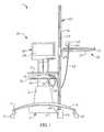
- FIG. 1is a front view of an illustrative embodiment of the medical imaging workstation
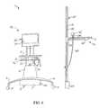
- FIG. 2is a side view of an illustrative embodiment of the medical imaging workstation
- FIG. 3is a top view of an illustrative embodiment of the medical imaging workstation, more particularly illustrating multi-positioning capability of an infrared camera provided on the medical imaging workstation;
- FIG. 4is a top view of an illustrative embodiment of the medical imaging workstation, more particularly illustrating imaging of a patient in implementation of an illustrative embodiment of the medical imaging workstation;
- FIG. 5is a functional block diagram of an illustrative embodiment of the medical imaging workstation
- FIG. 6is a front view of an illustrative embodiment of the medical imaging workstation, with the linear actuator detached from the cart of the workstation;
- FIG. 7is a functional block diagram of an alternative illustrative embodiment of the medical imaging workstation.
- the medical imaging workstation 1includes a medical-grade cart 2 which may have a cart frame 3 . Multiple cart legs 4 may extend outwardly from the cart frame 3 . Cart wheels 5 , each of which may be a castor-type wheel, for example and without limitation, may be provided on the respective cart legs 4 .
- a cart body 6may be provided on the cart frame 3 . As illustrated in FIG. 5 , in some embodiments a cart handle 7 may be provided on the cart body 6 or elsewhere on the cart 2 to facilitate pushing and/or pulling of the cart 2 across a floor or other surface (not illustrated) on the cart wheels 5 .
- a DC converter 56may be provided in the cart 2 .
- a power cord 63which may be adapted to plug into an AC power supply 62 such as a standard 120-volt household electrical outlet, for example and without limitation, may be connected to the DC converter 56 and extend from the cart 2 .
- a vertical support frame 10may extend upwardly from the cart body 6 of the cart 2 .
- a work platform 13may be mounted on the support frame 10 , such as via a platform support bracket 12 of suitable design.
- a keyboard support platform 16may additionally be mounted on the support frame 10 . As illustrated in FIG. 2 , in some embodiments the keyboard support platform 16 may extend from the platform support bracket 12 .
- the work platform 13 and/or the keyboard support platform 16may be vertically adjustable on the support frame 10 according to the knowledge of those skilled in the art. For example, vertical adjustability of the work platform 13 and/or the keyboard support platform 16 on the support frame 10 may enable sitting or standing of an operator (not illustrated) at the medical imaging workstation 1 .
- a linear actuator 20may extend upwardly from the cart 2 .
- the linear actuator 20may include an actuator base 23 which may be attached to a side of the cart frame 3 according to the knowledge of those skilled in the art.
- the actuator base 23may be detachably attached to the cart frame 3 of the cart 2 via an actuator attachment bracket 24 .
- a generally elongated actuator housing 21extends upwardly from the actuator base 23 .
- an elongated actuator housing slot 22may be provided in the actuator housing 21 and may traverse substantially the entire length of the actuator housing 21 for purposes which will be hereinafter described.
- a support arm assembly 26may be provided on the linear actuator 20 .
- the support arm assembly 26may include an arm motor 27 which may be provided in the actuator housing 21 .
- the arm motor 27may be electrically connected to the DC converter 56 through a motor cable 57 .
- An arm sleeve 29may be slidably mounted and vertically adjustable on the actuator housing 21 , as indicated by the arrow 35 in FIG. 5 .
- a gear assembly 28 in the actuator housing 21may be drivingly engaged by the arm motor 27 and drivingly engage the arm sleeve 29 through the actuator housing slot 22 ( FIG. 1 ).
- the gear assembly 28may be any mechanism which is known by those skilled in the art that is capable of translating rotational motion of the arm motor 27 into vertical motion of the arm sleeve 29 on the actuator housing 21 .
- the gear assembly 28may be a lead screw, a ball screw or a belt drive, for example and without limitation.
- a motor control pendant 32may be connected to the arm motor 27 through a pendant cable 33 for user control of the arm motor 27 and selected upward and downward travel of the arm sleeve 29 on the linear actuator 20 .
- the support arm assembly 26may further include a generally elongated rail support arm 30 which extends outwardly from the arm sleeve 29 .
- the rail support arm 30may be oriented in generally perpendicular relationship with respect to the longitudinal axis of the linear actuator 20 .
- a camera support rail 31may be slidably mounted on the rail support arm 30 .
- the camera support rail 31may be capable of sliding back and forth on the rail support arm 30 as indicated by the arrow 31 a .
- a camera base 34may be provided on the camera support rail 31 to support an infrared camera 42 of a medical imaging system 36 , in typical application of the medical imaging workstation 1 which will be hereinafter described. As shown in FIG. 3 , the infrared camera 42 may be capable of pivoting with respect to the camera support rail 31 as indicated by the arrow 44 .
- the medical imaging workstation 1may be used to support a medical imaging system 36 .
- the medical imaging system 36may include a computer 38 having a computer monitor 39 ( FIGS. 1-4 ) which may be provided on the support frame 10 .
- the computer 38may be attached to the support frame 10 using a computer mount bracket 40 ( FIGS. 2 and 3 ).
- the computer mount bracket 40may be vertically adjustable on the support frame 10 according to the knowledge of those skilled in the art.
- the computer 38may be electrically connected to the DC converter 56 through a computer cable 58 .
- a keyboard 46 and a mouse 47may be provided on the keyboard support platform 46 and connected to the computer 38 through a keyboard/mouse cable 48 .
- a digital medical infrared camera 42may be provided on the camera base 34 on the camera support rail 31 .
- the infrared camera 42may be connected to the computer 38 through a video cable 43 and may be electrically connected to the DC converter 56 through a camera cable 45 .
- the infrared camera 42may be capable of being manually pivoted on the camera base 34 to a selected angle with respect to the camera support rail 31 , as indicated by the arrow 44 in FIG. 3 .
- the lateral position of the infrared camera 42 with respect to the linear actuator 20may be manually adjusted as indicated by the arrow 31 a by sliding the camera support rail 31 outwardly from the linear actuator 20 on the rail support arm 30 .
- the cart 2is transported to a desired location in a clinic, medical office, hospital or other medical facility.
- the cart 2may be transported across a floor (not illustrated) or other supporting surface by grasping the cart handle 7 ( FIG. 5 ) and rolling the cart wheels 5 on the floor or surface.
- the power cord 63may be plugged into the AC power supply 62 .
- the DC converter 56converts AC electrical power which is supplied by the AC power supply 62 into DC power that is supplied to the computer 38 and the arm motor 27 of the linear actuator 20 .
- the height of the work platform 13 and the keyboard support platform 16may be adjusted on the support frame 10 as needed according to the preferences of the user.
- a patient 52is positioned at a location generally in front of the IR camera 42 .
- the patient 52may be sitting, standing or reposed in some other position.
- the lateral position of the IR camera 42may be adjusted along the rail support arm 30 , as indicated by the arrow 31 a ( FIG. 5 ), and the angular position of the IR camera 42 relative to the rail support arm 30 may be adjusted as indicated by the arrow 44 ( FIG. 3 ), to locate the patient 52 within the optical field 50 of the IR camera 42 .
- Items (not illustrated)such as the patient's file, for example, may be placed on the work platform 13 . Accordingly, digital infrared images of the patient 52 can be captured by the IR camera 42 and transferred to the computer 38 .
- the digital infrared images of the patient 52can be displayed on the monitor 39 of the computer 38 and saved on the computer 38 typically for diagnostic purposes. It will be appreciated by those skilled in the art that the vertical adjustment capability of the arm sleeve 29 on the linear actuator 20 and the lateral adjustment capability of the IR camera 42 on the camera support rail 31 enables an imaging technician (not illustrated) to precisely adjust the vertical and horizontal positions of the IR camera 42 without having to move the patient 52 .
- the linear actuator 20can be detached from the cart 2 and disposed in a free-standing position at a selected distance from the cart 2 .
- the linear actuator 20may support the IR camera 42 in the desired proximity to the cart 2 , with the video cable 43 connecting the IR camera 42 to the computer 38 and the motor cable 57 connecting the arm motor 27 to the DC converter 56 on the cart 2 .
- an alternative illustrative embodiment of the medical imaging workstation 1 aincludes a battery 59 which may be electrically connected to the DC converter 56 .
- the arm motor 27 of the support arm assembly 26may be electrically connected to the battery 59 via the motor cable 57 .
- the computer 38may be electrically connected to the battery 59 via the computer cable 58 .
- the IR camera 42may be electrically connected to the battery 42 via the camera cable 45 .
- the battery 59may be rechargeable via the AC power supply 62 and the power cord 63 .
- the battery 59provides portable electrical power to the arm motor 27 , the computer 38 and the IR camera 42 . This expedient facilitates use of the medical imaging workstation 1 at a location which is remote from the AC power supply 62 .
Landscapes
- Life Sciences & Earth Sciences (AREA)
- Health & Medical Sciences (AREA)
- Medical Informatics (AREA)
- Biophysics (AREA)
- Pathology (AREA)
- Engineering & Computer Science (AREA)
- Biomedical Technology (AREA)
- Heart & Thoracic Surgery (AREA)
- Physics & Mathematics (AREA)
- Molecular Biology (AREA)
- Surgery (AREA)
- Animal Behavior & Ethology (AREA)
- General Health & Medical Sciences (AREA)
- Public Health (AREA)
- Veterinary Medicine (AREA)
- Endoscopes (AREA)
Abstract
Description
Claims (10)
Priority Applications (1)
| Application Number | Priority Date | Filing Date | Title |
|---|---|---|---|
| US12/380,518US8172242B1 (en) | 2008-03-06 | 2009-02-27 | Medical imaging workstation |
Applications Claiming Priority (2)
| Application Number | Priority Date | Filing Date | Title |
|---|---|---|---|
| US6840908P | 2008-03-06 | 2008-03-06 | |
| US12/380,518US8172242B1 (en) | 2008-03-06 | 2009-02-27 | Medical imaging workstation |
Publications (1)
| Publication Number | Publication Date |
|---|---|
| US8172242B1true US8172242B1 (en) | 2012-05-08 |
Family
ID=46001997
Family Applications (1)
| Application Number | Title | Priority Date | Filing Date |
|---|---|---|---|
| US12/380,518Expired - Fee RelatedUS8172242B1 (en) | 2008-03-06 | 2009-02-27 | Medical imaging workstation |
Country Status (1)
| Country | Link |
|---|---|
| US (1) | US8172242B1 (en) |
Cited By (10)
| Publication number | Priority date | Publication date | Assignee | Title |
|---|---|---|---|---|
| US20100145160A1 (en)* | 2006-08-30 | 2010-06-10 | Jacques Cinqualbre | Multimedia, multiservice and connectable mobile assembly for diagnosis, prescriptions, medical checkups and nursing care |
| US20120306994A1 (en)* | 2011-06-06 | 2012-12-06 | Ted Schwartz | Mobile conferencing system |
| US20140110913A1 (en)* | 2012-10-23 | 2014-04-24 | Spinesmith Partners, L.P. | Automated work station for point-of-care cell and biological fluid processing |
| US20140291540A1 (en)* | 2013-03-29 | 2014-10-02 | Canon Kabushiki Kaisha | Radiation generating apparatus and radiographic imaging system |
| US9179493B1 (en)* | 2014-04-17 | 2015-11-03 | Huntingdon Telemed, LLC | Medical cart system |
| US20160367329A1 (en)* | 2014-02-17 | 2016-12-22 | Claronav Inc. | Medical cart |
| US20170146464A1 (en)* | 2014-06-02 | 2017-05-25 | Korea Institute Of Industrial Technology | Method of optical inspection on carbon fiber reinforced plastics components |
| USD908303S1 (en)* | 2018-03-05 | 2021-01-19 | Ergotron, Inc. | Workstation |
| US20230196576A1 (en)* | 2021-12-20 | 2023-06-22 | Glaxosmithkline Consumer Healthcare Holdings (Us) Llc | Thermal scanner for joint health |
| US20240415391A1 (en)* | 2015-03-10 | 2024-12-19 | Brain Tunnelgenix Technologies Corp. | Devices, apparatuses, systems, and methods for measuring temperature of an abtt terminus |
Citations (13)
| Publication number | Priority date | Publication date | Assignee | Title |
|---|---|---|---|---|
| US3801790A (en) | 1972-03-15 | 1974-04-02 | Siemens Ag | Movable x-ray examining device |
| US5206894A (en) | 1992-04-16 | 1993-04-27 | Remote Technologies, Inc., A Ct Corp. | X-ray system accessory |
| US5425069A (en) | 1993-11-26 | 1995-06-13 | Lorad Corporation | Mobile X-ray apparatus |
| US5475730A (en)* | 1994-08-24 | 1995-12-12 | John K. Grady | Telescoping X-ray support arms |
| US6007243A (en) | 1996-02-21 | 1999-12-28 | Lunar Corporation | Combined mobile x-ray imaging system and monitor cart |
| US6131680A (en)* | 1996-05-20 | 2000-10-17 | Toyota Jidosha Kabushiki Kaisha | Power output apparatus and method of controlling the same |
| US6193415B1 (en) | 1998-07-31 | 2001-02-27 | Shimadzu Corporation | Mobile device for X-ray apparatus |
| US6237707B1 (en) | 1999-02-18 | 2001-05-29 | Hologic, Inc. | Motion controlling system for motorized medical equipment carriage |
| US6851853B2 (en) | 2002-04-02 | 2005-02-08 | Shimadzu Corporation | X-ray device |
| US20060034427A1 (en)* | 2004-08-13 | 2006-02-16 | Brooks Jack J | Mobile digital radiography x-ray apparatus and system |
| US20080240535A1 (en)* | 2004-09-09 | 2008-10-02 | Massachusetts Institute Of Technology | Systems And Methods For Multi-Modal Imaging |
| US7438470B2 (en) | 2003-11-26 | 2008-10-21 | Carestream Health, Inc. | Mobile computed radiography |
| US7798710B1 (en)* | 2006-02-07 | 2010-09-21 | Barnes Gary T | Mobile radiography system and grid alignment |
- 2009
- 2009-02-27USUS12/380,518patent/US8172242B1/ennot_activeExpired - Fee Related
Patent Citations (14)
| Publication number | Priority date | Publication date | Assignee | Title |
|---|---|---|---|---|
| US3801790A (en) | 1972-03-15 | 1974-04-02 | Siemens Ag | Movable x-ray examining device |
| US5206894A (en) | 1992-04-16 | 1993-04-27 | Remote Technologies, Inc., A Ct Corp. | X-ray system accessory |
| US5425069A (en) | 1993-11-26 | 1995-06-13 | Lorad Corporation | Mobile X-ray apparatus |
| US5475730A (en)* | 1994-08-24 | 1995-12-12 | John K. Grady | Telescoping X-ray support arms |
| US6007243A (en) | 1996-02-21 | 1999-12-28 | Lunar Corporation | Combined mobile x-ray imaging system and monitor cart |
| US6131680A (en)* | 1996-05-20 | 2000-10-17 | Toyota Jidosha Kabushiki Kaisha | Power output apparatus and method of controlling the same |
| US6193415B1 (en) | 1998-07-31 | 2001-02-27 | Shimadzu Corporation | Mobile device for X-ray apparatus |
| US6237707B1 (en) | 1999-02-18 | 2001-05-29 | Hologic, Inc. | Motion controlling system for motorized medical equipment carriage |
| US6851853B2 (en) | 2002-04-02 | 2005-02-08 | Shimadzu Corporation | X-ray device |
| US7438470B2 (en) | 2003-11-26 | 2008-10-21 | Carestream Health, Inc. | Mobile computed radiography |
| US20060034427A1 (en)* | 2004-08-13 | 2006-02-16 | Brooks Jack J | Mobile digital radiography x-ray apparatus and system |
| US7016467B2 (en) | 2004-08-13 | 2006-03-21 | Jack Jerome Brooks | Mobile digital radiography x-ray apparatus and system |
| US20080240535A1 (en)* | 2004-09-09 | 2008-10-02 | Massachusetts Institute Of Technology | Systems And Methods For Multi-Modal Imaging |
| US7798710B1 (en)* | 2006-02-07 | 2010-09-21 | Barnes Gary T | Mobile radiography system and grid alignment |
Cited By (15)
| Publication number | Priority date | Publication date | Assignee | Title |
|---|---|---|---|---|
| US20100145160A1 (en)* | 2006-08-30 | 2010-06-10 | Jacques Cinqualbre | Multimedia, multiservice and connectable mobile assembly for diagnosis, prescriptions, medical checkups and nursing care |
| US20120306994A1 (en)* | 2011-06-06 | 2012-12-06 | Ted Schwartz | Mobile conferencing system |
| US8988483B2 (en)* | 2011-06-06 | 2015-03-24 | Ted Schwartz | Mobile conferencing system |
| US20140110913A1 (en)* | 2012-10-23 | 2014-04-24 | Spinesmith Partners, L.P. | Automated work station for point-of-care cell and biological fluid processing |
| US9463069B2 (en)* | 2012-10-23 | 2016-10-11 | Spinesmith Partners, L.P. | Automated work station for point-of-care cell and biological fluid processing |
| US20140291540A1 (en)* | 2013-03-29 | 2014-10-02 | Canon Kabushiki Kaisha | Radiation generating apparatus and radiographic imaging system |
| US20160367329A1 (en)* | 2014-02-17 | 2016-12-22 | Claronav Inc. | Medical cart |
| US9855109B2 (en)* | 2014-02-17 | 2018-01-02 | Claronav Inc. | Medical cart |
| US9298885B2 (en)* | 2014-04-17 | 2016-03-29 | Huntingdon Telemed, LLC | Medical cart system |
| US9179493B1 (en)* | 2014-04-17 | 2015-11-03 | Huntingdon Telemed, LLC | Medical cart system |
| US20170146464A1 (en)* | 2014-06-02 | 2017-05-25 | Korea Institute Of Industrial Technology | Method of optical inspection on carbon fiber reinforced plastics components |
| US20240415391A1 (en)* | 2015-03-10 | 2024-12-19 | Brain Tunnelgenix Technologies Corp. | Devices, apparatuses, systems, and methods for measuring temperature of an abtt terminus |
| US10234403B2 (en)* | 2015-06-02 | 2019-03-19 | Korea Institute Of Industrial Technology | Device and method of optical inspection on carbon fiber reinforced plastics components |
| USD908303S1 (en)* | 2018-03-05 | 2021-01-19 | Ergotron, Inc. | Workstation |
| US20230196576A1 (en)* | 2021-12-20 | 2023-06-22 | Glaxosmithkline Consumer Healthcare Holdings (Us) Llc | Thermal scanner for joint health |
Similar Documents
| Publication | Publication Date | Title |
|---|---|---|
| US8172242B1 (en) | Medical imaging workstation | |
| US9968502B2 (en) | System and process of locating a medical imaging device | |
| US9973736B2 (en) | Mobile workstation having navigation camera | |
| US8406846B2 (en) | Mammographic apparatus | |
| US9398675B2 (en) | Mobile imaging apparatus | |
| US11903889B2 (en) | Adjustable cervical traction assemblies for person support apparatuses | |
| US9055912B2 (en) | Supporting device and intra-operative imaging device having the supporting device | |
| US10478361B2 (en) | Person lifting devices and methods for operating person lifting devices | |
| KR100769615B1 (en) | Radiographic imaging apparatus | |
| US10993685B2 (en) | Device for remote fluoroscopy, nearby fluoroscopy and radiology | |
| JP2014533188A (en) | Apparatus, system and method for generating X-ray images | |
| US20160183898A1 (en) | A mammographic device | |
| US20160174915A1 (en) | Deployable guard for mobile x-ray system | |
| JP6879792B2 (en) | Metal detector for detecting the insertion of surgical instruments into hollow tubes | |
| CN105496440A (en) | Neurology cerebrovascular angiography machine | |
| CN103735315B (en) | A kind of orthopedic navigation device | |
| EP4159133A1 (en) | Positron emission tomography (pet)-scanning device | |
| CN104068883A (en) | Radiation generating apparatus and radiographic imaging system | |
| CN203619685U (en) | Orthopedic navigation device | |
| US8496380B2 (en) | Medical radiological device and radiological system | |
| US20160157792A1 (en) | Fixed/mobile patient handling system | |
| CN215272859U (en) | Cone beam CT scanning system | |
| CN216622859U (en) | Movable film display device for neurology department | |
| CN105030335A (en) | Neurosurgical monitoring and microscopic operation device | |
| CN204106195U (en) | Support, especially ground support |
Legal Events
| Date | Code | Title | Description |
|---|---|---|---|
| ZAAA | Notice of allowance and fees due | Free format text:ORIGINAL CODE: NOA | |
| ZAAB | Notice of allowance mailed | Free format text:ORIGINAL CODE: MN/=. | |
| STCF | Information on status: patent grant | Free format text:PATENTED CASE | |
| FPAY | Fee payment | Year of fee payment:4 | |
| FEPP | Fee payment procedure | Free format text:MAINTENANCE FEE REMINDER MAILED (ORIGINAL EVENT CODE: REM.); ENTITY STATUS OF PATENT OWNER: SMALL ENTITY | |
| FEPP | Fee payment procedure | Free format text:7.5 YR SURCHARGE - LATE PMT W/IN 6 MO, SMALL ENTITY (ORIGINAL EVENT CODE: M2555); ENTITY STATUS OF PATENT OWNER: SMALL ENTITY | |
| MAFP | Maintenance fee payment | Free format text:PAYMENT OF MAINTENANCE FEE, 8TH YR, SMALL ENTITY (ORIGINAL EVENT CODE: M2552); ENTITY STATUS OF PATENT OWNER: SMALL ENTITY Year of fee payment:8 | |
| FEPP | Fee payment procedure | Free format text:MAINTENANCE FEE REMINDER MAILED (ORIGINAL EVENT CODE: REM.); ENTITY STATUS OF PATENT OWNER: SMALL ENTITY | |
| LAPS | Lapse for failure to pay maintenance fees | Free format text:PATENT EXPIRED FOR FAILURE TO PAY MAINTENANCE FEES (ORIGINAL EVENT CODE: EXP.); ENTITY STATUS OF PATENT OWNER: SMALL ENTITY | |
| STCH | Information on status: patent discontinuation | Free format text:PATENT EXPIRED DUE TO NONPAYMENT OF MAINTENANCE FEES UNDER 37 CFR 1.362 | |
| FP | Lapsed due to failure to pay maintenance fee | Effective date:20240508 |