US8172098B2 - Modular rack assembly - Google Patents
Modular rack assemblyDownload PDFInfo
- Publication number
- US8172098B2 US8172098B2US12/436,771US43677109AUS8172098B2US 8172098 B2US8172098 B2US 8172098B2US 43677109 AUS43677109 AUS 43677109AUS 8172098 B2US8172098 B2US 8172098B2
- Authority
- US
- United States
- Prior art keywords
- cross beam
- support post
- extending
- support
- end support
- Prior art date
- Legal status (The legal status is an assumption and is not a legal conclusion. Google has not performed a legal analysis and makes no representation as to the accuracy of the status listed.)
- Expired - Fee Related, expires
Links
- 230000000712assemblyEffects0.000description9
- 238000000429assemblyMethods0.000description9
- 239000000463materialSubstances0.000description2
- 238000004873anchoringMethods0.000description1
- 238000010276constructionMethods0.000description1
- 238000004519manufacturing processMethods0.000description1
- 230000004048modificationEffects0.000description1
- 238000012986modificationMethods0.000description1
- 238000004806packaging method and processMethods0.000description1
- 230000006641stabilisationEffects0.000description1
- 238000011105stabilizationMethods0.000description1
- 238000003466weldingMethods0.000description1
- 239000002023woodSubstances0.000description1
Images


Classifications
- A—HUMAN NECESSITIES
- A47—FURNITURE; DOMESTIC ARTICLES OR APPLIANCES; COFFEE MILLS; SPICE MILLS; SUCTION CLEANERS IN GENERAL
- A47B—TABLES; DESKS; OFFICE FURNITURE; CABINETS; DRAWERS; GENERAL DETAILS OF FURNITURE
- A47B47/00—Cabinets, racks or shelf units, characterised by features related to dismountability or building-up from elements
- A47B47/02—Cabinets, racks or shelf units, characterised by features related to dismountability or building-up from elements made of metal only
- A47B47/021—Racks or shelf units
- A—HUMAN NECESSITIES
- A47—FURNITURE; DOMESTIC ARTICLES OR APPLIANCES; COFFEE MILLS; SPICE MILLS; SUCTION CLEANERS IN GENERAL
- A47B—TABLES; DESKS; OFFICE FURNITURE; CABINETS; DRAWERS; GENERAL DETAILS OF FURNITURE
- A47B57/00—Cabinets, racks or shelf units, characterised by features for adjusting shelves or partitions
- A47B57/06—Cabinets, racks or shelf units, characterised by features for adjusting shelves or partitions with means for adjusting the height of the shelves
- A47B57/20—Cabinets, racks or shelf units, characterised by features for adjusting shelves or partitions with means for adjusting the height of the shelves consisting of tongues, pins or similar projecting means coacting with openings
- A47B57/22—Cabinets, racks or shelf units, characterised by features for adjusting shelves or partitions with means for adjusting the height of the shelves consisting of tongues, pins or similar projecting means coacting with openings characterised by shape or orientation of opening, e.g. keyhole-shaped
- A—HUMAN NECESSITIES
- A47—FURNITURE; DOMESTIC ARTICLES OR APPLIANCES; COFFEE MILLS; SPICE MILLS; SUCTION CLEANERS IN GENERAL
- A47B—TABLES; DESKS; OFFICE FURNITURE; CABINETS; DRAWERS; GENERAL DETAILS OF FURNITURE
- A47B87/00—Sectional furniture, i.e. combinations of complete furniture units, e.g. assemblies of furniture units of the same kind such as linkable cabinets, tables, racks or shelf units
- A47B87/02—Sectional furniture, i.e. combinations of complete furniture units, e.g. assemblies of furniture units of the same kind such as linkable cabinets, tables, racks or shelf units stackable ; stackable and linkable
- A47B87/0207—Stackable racks, trays or shelf units
- B—PERFORMING OPERATIONS; TRANSPORTING
- B25—HAND TOOLS; PORTABLE POWER-DRIVEN TOOLS; MANIPULATORS
- B25H—WORKSHOP EQUIPMENT, e.g. FOR MARKING-OUT WORK; STORAGE MEANS FOR WORKSHOPS
- B25H1/00—Work benches; Portable stands or supports for positioning portable tools or work to be operated on thereby
- B25H1/02—Work benches; Portable stands or supports for positioning portable tools or work to be operated on thereby of table type
- B—PERFORMING OPERATIONS; TRANSPORTING
- B25—HAND TOOLS; PORTABLE POWER-DRIVEN TOOLS; MANIPULATORS
- B25H—WORKSHOP EQUIPMENT, e.g. FOR MARKING-OUT WORK; STORAGE MEANS FOR WORKSHOPS
- B25H1/00—Work benches; Portable stands or supports for positioning portable tools or work to be operated on thereby
- B25H1/12—Work benches; Portable stands or supports for positioning portable tools or work to be operated on thereby with storage compartments
- A—HUMAN NECESSITIES
- A47—FURNITURE; DOMESTIC ARTICLES OR APPLIANCES; COFFEE MILLS; SPICE MILLS; SUCTION CLEANERS IN GENERAL
- A47B—TABLES; DESKS; OFFICE FURNITURE; CABINETS; DRAWERS; GENERAL DETAILS OF FURNITURE
- A47B47/00—Cabinets, racks or shelf units, characterised by features related to dismountability or building-up from elements
- A47B47/02—Cabinets, racks or shelf units, characterised by features related to dismountability or building-up from elements made of metal only
- A47B47/021—Racks or shelf units
- A47B47/027—Racks or shelf units with frames only
Definitions
- the present inventionrelates to a modular rack assembly. While there are a variety of modular rack assemblies that have been designed to store various items, they are not easily configurable for shipping. Further, conventional modular racks are not formed of a simple construction and may be expensive to manufacture and difficult to assemble and adjust.
- An embodiment of the present inventionprovides an end support unit for supporting the ends of at least one front and one rear cross beam including: a generally vertical front support post having at least one column of slots along its length for receiving at least one slot engaging member of the front cross beam; a generally vertical rear support post having at least one column of slots along its length for receiving at least one slot engaging member of the rear cross beam; a generally horizontal upper brace fixedly attached to and extending from the upper end of the front support post to the upper end of the rear support post; a generally horizontal lower brace fixedly attached to and extending from the lower end of the front support post to the lower end of the rear support post; and at least one diagonal brace fixedly attached to and extending diagonally between the front support post and the rear support post.
- the upper bracemay have at least one hole for receiving the shaft of a connector for securely mounting a secondary component to the end support unit.
- the lower bracemay have at least one hole for receiving the shaft of an anchor for securely anchoring the end support unit to a floor location or a connector for securely mounting a secondary component to the end support unit.
- the slotsmay be key-hole shaped.
- the slot engaging membersmay be rivets.
- the slotsmay be wedge-shaped.
- the slot engaging membersmay be lances.
- the end support unitsmay be about 3, inches wide, about 17, inches deep, and about 36 inches high.
- the support postsmay be c-shaped.
- the bracesmay be c-shaped.
- Each end support unitincludes: a generally vertical front support post having at least one column of slots along its length for receiving at least one slot engaging member of the front cross beam; a generally vertical rear support post having at least one column of slots along its length for receiving at least one slot engaging member of the rear cross beam; a generally horizontal upper brace fixedly attached to and extending from the upper end of the front support post to the upper end of the rear support post; a generally horizontal lower brace fixedly attached to and extending from the lower end of the front support post to the lower end of the rear support post; at least one diagonal brace fixedly attached to and extending diagonally between the front support post and the rear support post; and a pair of connectors extending through holes in the lower brace of the upper end support unit and the upper brace of the lower end support unit to secure the upper end support unit to the lower end support unit.
- Each connectormay include a bolt, a lock washer, and a nut.
- Each end support unitincludes: a generally vertical front support post having at least one column of slots along its length for receiving at least one slot engaging member of the front cross beam; a generally vertical rear support post having at least one column of slots along its length for receiving at least one slot engaging member of the rear cross beams; a generally horizontal upper brace fixedly attached to and extending from the upper end of the front support post to the upper end of the rear support post; a generally horizontal lower brace fixedly attached to and extending from the lower end of the front support post to the lower end of the rear support post; and at least one diagonal brace fixedly attached to and extending diagonally between the front support post and the rear support post; at least one front cross beam, wherein the at least one front cross beam is mounted on and extending between the left and right front support posts of the left and right end support units; at least one rear cross beam, wherein the at
- the storage rackmay include four pairs of front and rear cross beams, four shelves, and four end support units, and wherein the disassembled storage rack is packaged in a space that is about 39, inches by about 17, inches by about 16, inches.
- the front and rear cross beamsmay include at each end an L-shaped flange with a pair of slot engaging members extending inwardly from the flange to engage the slots.
- the front and rear cross beamsmay include a ledge for receiving the shelf panel.
- Each end support unitincludes: a generally vertical front support post having at least one column of slots along its length for receiving at least one slot engaging member of the front cross beam; a generally vertical rear support post having at least one column of slots along its length for receiving at least one slot engaging member of the rear cross beam; a generally horizontal upper brace fixedly attached to and extending from the upper end of the front support post to the upper end of the rear support post; a generally horizontal lower brace fixedly attached to and extending from the lower end of the front support post to the lower end of the rear support post; at least one diagonal brace fixedly attached to and extending diagonally between the front support post and the rear support post; an upper front cross beam extending between the upper ends of the front support posts of the right and left end support units; an upper rear cross beam extending between the upper ends of the rear support posts of the right and left end support units; a lower rear cross beam extending between the upper ends of the rear support posts of the right and left end support units; a lower rear cross beam extending between
- the generally vertical panelmay include pegboard.
- the generally vertical panelmay include upper and lower pegboard panels connected by an elongated strip connector having a generally H-shaped cross-sectional configuration that forms a pair of grooves for receiving the lower end of the upper pegboard panel and the upper edge of the lower pegboard panel.
- the workbench assemblymay further include a cover mounted over the upper braces.
- FIG. 1is a front perspective view of a storage rack according to an embodiment of the present invention.
- FIG. 1 ais a cross-sectional view of a portion of the storage rack of FIG. 1 .
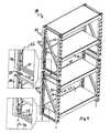
- FIG. 2is a front perspective view of a storage rack according to another embodiment of the present invention.
- FIG. 3is an exploded view of the storage rack shown in FIG. 2 .
- FIG. 4is a front perspective view of a storage rack according to another embodiment of the present invention.
- FIG. 5is perspective view of the components of the storage rack shown in FIGS. 2-4 arranged for shipping.
- FIG. 6is an end-view of the exemplary storage racks shown in FIGS. 2-4 assembled for shipping.
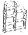
- FIG. 7is a perspective view of a storage rack according to another embodiment of the present invention.
- FIG. 8is a perspective view of a storage rack according to another embodiment of the present invention.
- FIG. 9is a perspective view of a storage rack according to another embodiment of the present invention.
- FIG. 10is a perspective view of a storage rack according to another embodiment of the present invention.
- FIG. 11is a perspective view of a storage rack according to another embodiment of the present invention.
- FIG. 12is a perspective view of a storage rack according to another embodiment of the present invention.
- the rack assembly 10comprises right and left end support units 12 , each end support unit 12 comprising a front support post 13 , a rear support post 14 , an upper brace 18 , a lower brace 20 , and a diagonal brace 22 .
- the upper, lower and diagonal braces 18 , 20 , 22are fixedly attached at their ends, preferably by welding, to the front and rear support posts 13 and 14 .
- the front and rear support posts 13 and 14include at least one column of aligned slots 16 for receiving slot engaging members of cross beams 26 , 28 .
- the front and rear support posts 13 and 14 of the end support units 12may include right and left columns of slots 16 .
- Front cross beams 26are boltlessly mounted at their ends to the front posts 13 of right and left end support units 12 .
- Rear cross beams 28are likewise boltlessly mounted at their ends to the rear support posts 14 of the right and left end support units 12 at the same elevations as the front cross beams 26 .
- cross-sectional configuration of the support posts and bracesmay vary as desired.
- the cross-sectional configuration of the posts and bracesare generally C-shaped.
- the cross-sectional configuration of the cross beamsmay vary as desired.
- the cross beams 26 , 28have cross-sectional configurations as shown in FIG. 1 a .
- the cross beamshave a ledge for receiving a shelf panel 32 .
- the cross beams 26 and 28have an L-shaped flange 29 at each end.
- a pair of slot engaging members (in this case lances) 30extend inwardly from the flange 29 to engage wedge-shaped slots 16 in the support posts 13 and 14 .
- the slots 16 and slot engaging members 30may also vary as desired.
- the slotshave a key-hole shape and the slot engaging members are rivets that extend inwardly from the ends of the cross beams.
- the dimensions of the end support units 12 and cross beams 26 and 28may also vary.
- the end support units 12are about 3, inches high and about 17, inches deep.
- the length of the cross beamsis about 39, inches so that the overall width of the rack is about 41, inches.
- the stacked rack assembly 38comprises right and left end support assemblies 40 , each end support assembly 40 including a pair of end support units 12 a , 12 b , stacked one on top of the other.
- the upper end support unit 12 ais securely mounted to the lower end support unit 12 b , with connectors 42 , e.g., bolts which extend through holes 24 in the lower brace 20 of the upper end support unit 12 a , and aligned holes 24 in the upper brace 18 of the lower end support unit 12 b .
- the bolts 42are secured with appropriate lock washers and nuts. It is to be understood that any suitable connector may be used.
- a plurality of front and rear cross beams 26 and 28are boltlessly mounted to the front and rear support posts 13 and 14 of the end support units 12 that make up the end support assemblies 40 .
- Shelf panels 32are positioned between and supported at their front and rear edge portions by the front and rear cross beams 26 and 28 .
- the stacked rack assembly 38can be anchored at a particular floor location by means of anchors 28 or the like which extend through holes 24 in the lower brace 20 of the lower end support unit 12 b , and into the floor.
- the type of anchorwill vary depending on the material of the floor. For example, expandable wedge anchors, sleeve anchors, etc., as are well-known in the art may be used with concrete floors, whereas leg bolts or the like may be used for wood floors.
- FIG. 4Another modular rack assembly 44 according to an embodiment of the present invention is shown in FIG. 4 .
- the upper and lower end support units 12 a , and 12 bmay be secured together by means of front and rear cross beams 26 and 28 wherein the upper slot engaging members 30 at each end of the cross beams engage the lowest slot 16 in the front and rear posts 13 and 14 of the upper end support unit 12 a , and the lower slot-engaging members 30 of the cross beams engage the uppermost slot 16 of the front and rear post 13 and 14 of the lower end support unit 12 b .
- the upper and lower end support units 12 a , and 12 bmay be further secured together by bolts 42 or the like, as described with respect to FIGS. 2 and 3 .
- a 72-inch high by 17, inch deep by 41 inch wide rack assembly having four pairs of front and rear cross-beams and four shelvesmay be packaged in a space having the dimensions 39, inches by 17, inches by less than 16, inches.
- Such a packaged arrangementprovides significant cost savings as compared to racks having 72-inch long side support units. For example, this set of dimensions enables three packages to fit on a standard forty inch by forty-eight inch pallet.
- An exemplary arrangement of the components for packagingis shown in FIGS. 5 and 6 .
- the end support units 12may also be used as intermediate support units in larger shelf and/or bench assemblies.
- FIG. 7shows another exemplary assembly comprising four end-support units 12 used to form an elongated workbench with three shelf panels 32 .
- FIG. 8shows another exemplary assembly including left and middle support assemblies 40 a, , 40 b, , which each include three stacked end support units 12 .
- the right support assembly 40 cincludes two stacked end support units 12 .
- Cross-beams 26 and 28are mounted between the left and middle end-support assemblies 40 a , and 40 b , to provide support for four shelf panels 32 .
- Cross-beams 26 and 28are mounted on and extended between the middle and right support unit assemblies 40 b , and 40 c , to provide three shelf panels 32 , as shown.
- FIGS. 9 and 10show other exemplary assemblies using end support units 12 .
- the present inventionalso provides work benches that utilize the benefits of the end support units 12 described above.
- a work bench 50with a pair of opposing right and left end support units 12 , and front and rear cross-beams 26 and 28 are mounted on and extend between the left and right front and rear support posts 13 and 14 of the right and left end support units 12 at the top of the support posts 13 and 14 .
- a lower rear cross-beam 28extends between the rear posts 13 of the right and left end support units 12 at a lower portion of those support posts.
- a panel 32is supported at its front and rear edge portions by the upper front and rear cross beams 26 and 28 .
- a cover 52is mounted over the upper braces 18 of the right and left end support units 12 to create a generally flat surface at about the same level as the top surfaces of shelf panel 32 .
- the cover 52has the same cross-sectional configuration as the support posts 13 , 14 of the end-support units 12 , but without the slots.
- a pair of upright supports 54extend upwardly from the rearward portion of the end support units 12 .
- the uprights supports 54are made of the same material and have the same cross-sectional configuration of the support posts 13 , 14 of the end-support units 12 .
- the upright supports 54have a generally horizontal flange 56 at their lower ends.
- the flange 56extends forwardly and has a hole that aligns with holes in the cover 52 and upper brace 18 of the end support units 12 .
- the upright supports 54may be secured to the end support units 12 by connectors, such as bolts as previously described.
- a cross-beam 58is mounted at its ends to and extends between top ends of the left and right upright supports 54 .
- a pegboard assembly 60which extends between the left and right upright supports 54 and between the top of the workbench 50 and the cross-beam 58 at the upper end of the upright supports 54 .
- the pegboard assembly 60preferably comprises two pegboard panels 62 a , and 62 b , connected together by a plastic strip connector 64 having an H-shaped cross-sectional configuration.
- a connector 64comprises a pair of grooves or recesses for receiving the lower edge of the upper pegboard panel 62 a , and the upper edge of a lower pegboard panel 62 b.
- the workbench 50comprises a drawer assembly. Any suitable drawer assembly may be used. Likewise, the workbench 50 could be provided with a lower shelf for storage purposes, if desired.
- FIG. 12there is shown another exemplary workbench constructed according to another embodiment of the present invention.
- the workbenchcomprises two workbench assemblies as generally as described in FIG. 11 , except that the middle end support unit 12 and upright support 54 provide common support for both workbench units.
Landscapes
- Engineering & Computer Science (AREA)
- Mechanical Engineering (AREA)
- Assembled Shelves (AREA)
Abstract
Description
Claims (3)
Priority Applications (2)
| Application Number | Priority Date | Filing Date | Title |
|---|---|---|---|
| US12/436,771US8172098B2 (en) | 2008-05-06 | 2009-05-06 | Modular rack assembly |
| US13/360,543US9144303B2 (en) | 2008-05-06 | 2012-01-27 | Modular rack assembly |
Applications Claiming Priority (2)
| Application Number | Priority Date | Filing Date | Title |
|---|---|---|---|
| US5099208P | 2008-05-06 | 2008-05-06 | |
| US12/436,771US8172098B2 (en) | 2008-05-06 | 2009-05-06 | Modular rack assembly |
Related Child Applications (1)
| Application Number | Title | Priority Date | Filing Date |
|---|---|---|---|
| US13/360,543ContinuationUS9144303B2 (en) | 2008-05-06 | 2012-01-27 | Modular rack assembly |
Publications (2)
| Publication Number | Publication Date |
|---|---|
| US20090277854A1 US20090277854A1 (en) | 2009-11-12 |
| US8172098B2true US8172098B2 (en) | 2012-05-08 |
Family
ID=41266027
Family Applications (2)
| Application Number | Title | Priority Date | Filing Date |
|---|---|---|---|
| US12/436,771Expired - Fee RelatedUS8172098B2 (en) | 2008-05-06 | 2009-05-06 | Modular rack assembly |
| US13/360,543Expired - Fee RelatedUS9144303B2 (en) | 2008-05-06 | 2012-01-27 | Modular rack assembly |
Family Applications After (1)
| Application Number | Title | Priority Date | Filing Date |
|---|---|---|---|
| US13/360,543Expired - Fee RelatedUS9144303B2 (en) | 2008-05-06 | 2012-01-27 | Modular rack assembly |
Country Status (1)
| Country | Link |
|---|---|
| US (2) | US8172098B2 (en) |
Cited By (18)
| Publication number | Priority date | Publication date | Assignee | Title |
|---|---|---|---|---|
| US20130098856A1 (en)* | 2011-10-25 | 2013-04-25 | Edsal Manufacturing Co., Inc. | Dual function shelf unit |
| US20140116973A1 (en)* | 2012-10-29 | 2014-05-01 | Whirlpool Corporation | Rack shelving unit |
| US8985716B2 (en)* | 2012-11-07 | 2015-03-24 | Evans Consoles Corporation | Console module and modular console system |
| US20150114919A1 (en)* | 2013-10-30 | 2015-04-30 | Wan Young Lee | Storage rack |
| CN106175134A (en)* | 2015-01-29 | 2016-12-07 | Js产品有限公司 | There is the practical bracket including folding the end supports of cross member |
| US20180055222A1 (en)* | 2016-08-26 | 2018-03-01 | Evans Consoles Corporation | Modular console frame structure and console |
| US9924613B2 (en) | 2015-05-07 | 2018-03-20 | Revolution Display, Llc | Modular electronic production equipment support structures, module connectors and modules therefor, and related installations and methods |
| US20190030706A1 (en)* | 2017-07-30 | 2019-01-31 | Brennan Equipment and Manufacturing, Inc. | Pegboard Bracket |
| US20190038022A1 (en)* | 2017-08-03 | 2019-02-07 | Decolin Inc. | Bath shelving unit with stabilizing bar |
| US20190182978A1 (en)* | 2017-12-13 | 2019-06-13 | Ovh | Method for positioning a rack onto a base structure |
| US10368639B1 (en)* | 2018-07-09 | 2019-08-06 | Shenter Enterprise Co., Ltd. | Butt-joining and positioning structure of vertical bar with hook hole |
| US20190239640A1 (en)* | 2018-02-08 | 2019-08-08 | Alert Innovation Inc. | Modular structure for an automated storage and retrieval system |
| USD891152S1 (en)* | 2017-09-01 | 2020-07-28 | Evas Consoles Corporation | Slatted equipment mount |
| CN113581599A (en)* | 2020-04-30 | 2021-11-02 | 精实产品公司 | Stacking tray for storage racks |
| US11647833B2 (en) | 2020-09-16 | 2023-05-16 | Perfect Site LLC | Utility rack |
| US20230413995A1 (en)* | 2020-09-24 | 2023-12-28 | Michael D. Hornbacher | Freestanding ladder storage rack |
| US12185834B1 (en)* | 2023-10-12 | 2025-01-07 | Protrend Co., Ltd. | Screw-less and no rivet combined type shelf |
| US12383057B2 (en)* | 2023-07-14 | 2025-08-12 | Ll&T International, Llc | Knockdown bracing for shelving unit end frame |
Families Citing this family (21)
| Publication number | Priority date | Publication date | Assignee | Title |
|---|---|---|---|---|
| US20140263896A1 (en)* | 2013-03-13 | 2014-09-18 | Rapid Rack Industries,Inc. | Bracket and hook accessories for boltless shelving units |
| EP2837307A1 (en) | 2013-08-13 | 2015-02-18 | Zurecon Ag | Modular rack |
| FR3038888B1 (en)* | 2015-07-16 | 2017-07-21 | Vb-Trade | DRAINING TABLE, IN PARTICULAR FOR DRAINING BAGS OF LARGE VOLUMES CALLED BIG-BAG |
| JP6674617B2 (en)* | 2016-11-18 | 2020-04-01 | 株式会社サカエ | Metal rack |
| WO2018107267A1 (en)* | 2016-12-16 | 2018-06-21 | Peak Innovations Inc. | Shelving system |
| IT201700035962A1 (en)* | 2017-03-31 | 2018-10-01 | Rossetto Arredamenti Srl | ELEMENT OF FURNISHING, METHOD FOR ITS ASSEMBLY, AND RELATED ASSEMBLY KIT |
| CA3071446A1 (en) | 2017-08-09 | 2019-02-14 | Ronald K. HARRISON | Interchangeable base steel structure storage assembly |
| DE102017125349A1 (en)* | 2017-10-27 | 2019-05-02 | Topregal Gmbh | Set-up assembly for warehouses and workshops |
| US11344114B2 (en)* | 2018-03-12 | 2022-05-31 | Hangzhou United Tools Co., Ltd. | Shelf |
| US10400454B1 (en) | 2018-04-04 | 2019-09-03 | Frazier Industrial Company | Structural member with an anti-rotational feature |
| US11028586B2 (en) | 2018-04-04 | 2021-06-08 | Frazier Industrial Company | Structural member connection system |
| USD942784S1 (en)* | 2019-10-08 | 2022-02-08 | Brian Burge | Table |
| CN212474832U (en)* | 2020-04-30 | 2021-02-05 | 青岛蓝山贸易有限公司 | Combined cargo supporting device |
| WO2021228199A1 (en)* | 2020-05-14 | 2021-11-18 | Hangzhou Great Star Industrial Co., Ltd. | Industrial rack |
| US11882931B1 (en)* | 2020-10-28 | 2024-01-30 | Randall E. Arnall | Expandable shelf assembly |
| CN114552101A (en)* | 2022-03-25 | 2022-05-27 | 中创新航科技股份有限公司 | Subrack racks, energy storage racks and battery clusters |
| USD1050784S1 (en)* | 2022-05-16 | 2024-11-12 | Edsal Manufacturing Company, Llc | Shelving unit post with keyhole |
| USD1050780S1 (en)* | 2022-05-16 | 2024-11-12 | Edsal Manufacturing Company, Llc | Support beam of a shelving unit |
| USD1050781S1 (en)* | 2022-05-16 | 2024-11-12 | Edsal Manufacturing Company, Llc | Support beam of a shelving unit |
| US12011087B1 (en)* | 2023-04-20 | 2024-06-18 | Taiwan Shin Yeh Enterprise Co., Ltd. | Shelf device and shelf unit thereof |
| USD1040576S1 (en)* | 2024-04-18 | 2024-09-03 | Chaoming Qiu | Shelves |
Citations (26)
| Publication number | Priority date | Publication date | Assignee | Title |
|---|---|---|---|---|
| US1688533A (en)* | 1926-10-29 | 1928-10-23 | Stanley Works | Combination workbench and tool holder |
| US2815130A (en)* | 1956-02-06 | 1957-12-03 | Norvin H Franks | Shelving unit |
| US2918176A (en)* | 1957-02-25 | 1959-12-22 | Allen Iron & Steel Company | Storage rack |
| US2984363A (en)* | 1958-07-24 | 1961-05-16 | Mechanical Handling Sys Inc | Adjustable rack |
| US3042221A (en)* | 1960-08-19 | 1962-07-03 | Acme Steel Co | Pallet rack |
| US3048245A (en)* | 1960-02-29 | 1962-08-07 | Arean Eastern Ltd | Locking mechanism |
| US3072262A (en)* | 1959-06-24 | 1963-01-08 | Allen Iron & Steel Company | Storage racks |
| US3095975A (en)* | 1961-05-15 | 1963-07-02 | Allen Iron & Steel Company | Storage rack |
| US3142386A (en)* | 1960-04-15 | 1964-07-28 | Paltier Corp | Pallet rack |
| US3157424A (en)* | 1962-12-10 | 1964-11-17 | Palmer Shile Co | Storage rack |
| US3194407A (en)* | 1963-12-10 | 1965-07-13 | Altrui Thomas N D | Convertible storage rack |
| US3392848A (en)* | 1966-06-06 | 1968-07-16 | Interlake Steel Corp | Pallet rack |
| US3434436A (en)* | 1967-01-20 | 1969-03-25 | Creative Environments Inc | Collapsible workbench |
| US3465898A (en)* | 1967-05-19 | 1969-09-09 | Unarco Industries | Connections for tiered storage rack units |
| US4450775A (en)* | 1983-01-17 | 1984-05-29 | Brendle David A | Merchandise display device |
| US5012938A (en)* | 1990-02-16 | 1991-05-07 | S&K Enterprises, Inc. | Storage rack corner post |
| US5553551A (en)* | 1993-08-25 | 1996-09-10 | Crombie; Terry | Interlocking modular bench system |
| US5918750A (en)* | 1997-10-24 | 1999-07-06 | The Sports Authority Michigan, Inc. | Fixture for displaying merchandise |
| US20030094124A1 (en)* | 2001-11-20 | 2003-05-22 | Wishart Andrew S. | Modular pallet display system |
| US20030155319A1 (en)* | 2001-05-25 | 2003-08-21 | Wishart Andrew S. | Modular rack conversion apparatus and method |
| US6729371B2 (en)* | 2001-02-05 | 2004-05-04 | Kevin Sheahan | Workbench |
| US6786162B1 (en)* | 2003-02-20 | 2004-09-07 | Randy E. Volkmer | Space-saver workbench |
| US20050016943A1 (en)* | 2003-07-21 | 2005-01-27 | Dick Spencer B. | System for industrial workspace organization |
| US20070193190A1 (en)* | 2006-01-27 | 2007-08-23 | Konstant Products, Inc. | Reinforced and bolted rack truss |
| US7350549B2 (en)* | 2005-05-31 | 2008-04-01 | Carter Mark C | Folding work bench |
| US20080272676A1 (en)* | 2007-05-04 | 2008-11-06 | Brian Eustace | Boltless cabinet assembly |
Family Cites Families (20)
| Publication number | Priority date | Publication date | Assignee | Title |
|---|---|---|---|---|
| US817689A (en)* | 1905-10-18 | 1906-04-10 | Frank Bentley | Brick-pallet. |
| US3506138A (en)* | 1968-04-03 | 1970-04-14 | Ray Steel Co | Storage rack system |
| GB1266689A (en)* | 1968-08-02 | 1972-03-15 | ||
| US3862691A (en)* | 1973-06-01 | 1975-01-28 | Lear Siegler Inc | Lock span shelving |
| AU513877B2 (en)* | 1977-03-21 | 1981-01-08 | Brambles Holdings Limited | Nesting units |
| US4155311A (en)* | 1978-07-13 | 1979-05-22 | Belvedere Company, Inc. | Stackable modular shelf apparatus |
| US4265501A (en)* | 1980-02-25 | 1981-05-05 | Halliburton Charles R | Modular Shelving |
| US4321873A (en)* | 1980-05-29 | 1982-03-30 | Nealis Perry M | Interlocking modular table unit |
| US4342397A (en)* | 1980-09-08 | 1982-08-03 | Halstrick Robert T | Fastenings for storage racks |
| US4940149A (en)* | 1988-07-15 | 1990-07-10 | Vineis Donna L | Building assembly system |
| US5452811A (en)* | 1994-01-13 | 1995-09-26 | Anchor Bay Packaging Corporation | Stackable partitioned shipping container |
| US5598791A (en)* | 1995-03-27 | 1997-02-04 | Taylor; Alva R. | Shelving apparatus and method of assembly |
| US6604640B1 (en)* | 2002-05-31 | 2003-08-12 | Stow International N.V. | Storage system |
| US6776297B2 (en)* | 2002-08-22 | 2004-08-17 | Hon Technology Inc. | Mobile shelving system and method of assembly |
| US7252202B2 (en)* | 2003-11-17 | 2007-08-07 | Edsal Manufacturing Co., Inc. | Cargo rack |
| US7128225B2 (en)* | 2003-11-17 | 2006-10-31 | Edsal Manufacturing Co., Inc. | Cargo rack |
| US9439508B2 (en)* | 2005-01-27 | 2016-09-13 | Edsal Manufacturing Company, Inc. | Outside wrap post coupler with assembly assist |
| US20070278169A1 (en)* | 2006-05-31 | 2007-12-06 | Allan Grainger | Frame adapted to be fitted inside an outer container |
| US9375102B2 (en)* | 2010-07-02 | 2016-06-28 | Edsal Manufacturing Company, Inc. | Portion of shelf and support for shelving unit |
| US8733564B2 (en)* | 2010-07-02 | 2014-05-27 | Edsal Manufacturing Co., Inc. | Variable configuration shelving apparatus and methods |
- 2009
- 2009-05-06USUS12/436,771patent/US8172098B2/ennot_activeExpired - Fee Related
- 2012
- 2012-01-27USUS13/360,543patent/US9144303B2/ennot_activeExpired - Fee Related
Patent Citations (32)
| Publication number | Priority date | Publication date | Assignee | Title |
|---|---|---|---|---|
| US1688533A (en)* | 1926-10-29 | 1928-10-23 | Stanley Works | Combination workbench and tool holder |
| US2815130A (en)* | 1956-02-06 | 1957-12-03 | Norvin H Franks | Shelving unit |
| US2918176A (en)* | 1957-02-25 | 1959-12-22 | Allen Iron & Steel Company | Storage rack |
| US2984363A (en)* | 1958-07-24 | 1961-05-16 | Mechanical Handling Sys Inc | Adjustable rack |
| US3072262A (en)* | 1959-06-24 | 1963-01-08 | Allen Iron & Steel Company | Storage racks |
| US3048245A (en)* | 1960-02-29 | 1962-08-07 | Arean Eastern Ltd | Locking mechanism |
| US3142386A (en)* | 1960-04-15 | 1964-07-28 | Paltier Corp | Pallet rack |
| US3042221A (en)* | 1960-08-19 | 1962-07-03 | Acme Steel Co | Pallet rack |
| US3095975A (en)* | 1961-05-15 | 1963-07-02 | Allen Iron & Steel Company | Storage rack |
| US3157424A (en)* | 1962-12-10 | 1964-11-17 | Palmer Shile Co | Storage rack |
| US3194407A (en)* | 1963-12-10 | 1965-07-13 | Altrui Thomas N D | Convertible storage rack |
| US3392848A (en)* | 1966-06-06 | 1968-07-16 | Interlake Steel Corp | Pallet rack |
| US3434436A (en)* | 1967-01-20 | 1969-03-25 | Creative Environments Inc | Collapsible workbench |
| US3465898A (en)* | 1967-05-19 | 1969-09-09 | Unarco Industries | Connections for tiered storage rack units |
| US4450775A (en)* | 1983-01-17 | 1984-05-29 | Brendle David A | Merchandise display device |
| US5012938A (en)* | 1990-02-16 | 1991-05-07 | S&K Enterprises, Inc. | Storage rack corner post |
| US5553551A (en)* | 1993-08-25 | 1996-09-10 | Crombie; Terry | Interlocking modular bench system |
| US5918750A (en)* | 1997-10-24 | 1999-07-06 | The Sports Authority Michigan, Inc. | Fixture for displaying merchandise |
| US6729371B2 (en)* | 2001-02-05 | 2004-05-04 | Kevin Sheahan | Workbench |
| US20070119808A1 (en)* | 2001-05-25 | 2007-05-31 | L&P Property Management Company | Modular rack conversion apparatus and method |
| US20030155319A1 (en)* | 2001-05-25 | 2003-08-21 | Wishart Andrew S. | Modular rack conversion apparatus and method |
| US6739463B2 (en)* | 2001-05-25 | 2004-05-25 | L&P Property Management Company | Modular rack conversion apparatus and method |
| US6978906B2 (en)* | 2001-05-25 | 2005-12-27 | L&P Property Management Company | Modular rack conversion apparatus and method |
| US20030094124A1 (en)* | 2001-11-20 | 2003-05-22 | Wishart Andrew S. | Modular pallet display system |
| US6786162B1 (en)* | 2003-02-20 | 2004-09-07 | Randy E. Volkmer | Space-saver workbench |
| US20050016943A1 (en)* | 2003-07-21 | 2005-01-27 | Dick Spencer B. | System for industrial workspace organization |
| US7350549B2 (en)* | 2005-05-31 | 2008-04-01 | Carter Mark C | Folding work bench |
| US7540312B2 (en)* | 2005-05-31 | 2009-06-02 | Carter Mark C | Folding work bench |
| US7565922B2 (en)* | 2005-05-31 | 2009-07-28 | Carter Mark C | Folding work bench |
| US7712493B2 (en)* | 2005-05-31 | 2010-05-11 | Carter Mark C | Folding work bench |
| US20070193190A1 (en)* | 2006-01-27 | 2007-08-23 | Konstant Products, Inc. | Reinforced and bolted rack truss |
| US20080272676A1 (en)* | 2007-05-04 | 2008-11-06 | Brian Eustace | Boltless cabinet assembly |
Cited By (33)
| Publication number | Priority date | Publication date | Assignee | Title |
|---|---|---|---|---|
| US9033164B2 (en) | 2011-10-25 | 2015-05-19 | Edsal Manufacturing Company, Inc. | Dual function shelf unit |
| US8695816B2 (en)* | 2011-10-25 | 2014-04-15 | Edsal Manufacturing Co., Inc. | Dual function shelf unit |
| US20130098856A1 (en)* | 2011-10-25 | 2013-04-25 | Edsal Manufacturing Co., Inc. | Dual function shelf unit |
| US9474370B2 (en) | 2011-10-25 | 2016-10-25 | Edsal Manufacturing Company, Inc. | Dual function shelf unit |
| US20140116973A1 (en)* | 2012-10-29 | 2014-05-01 | Whirlpool Corporation | Rack shelving unit |
| US9027767B2 (en)* | 2012-10-29 | 2015-05-12 | Whirlpool Corporation | Rack shelving unit |
| US8985716B2 (en)* | 2012-11-07 | 2015-03-24 | Evans Consoles Corporation | Console module and modular console system |
| US20150114919A1 (en)* | 2013-10-30 | 2015-04-30 | Wan Young Lee | Storage rack |
| CN106175134A (en)* | 2015-01-29 | 2016-12-07 | Js产品有限公司 | There is the practical bracket including folding the end supports of cross member |
| US10506880B2 (en)* | 2015-01-29 | 2019-12-17 | Js Products, Inc. | Utility rack having end supports with folding cross-members |
| US10806258B2 (en) | 2015-01-29 | 2020-10-20 | Js Products, Inc. | Utility rack having end supports with folding cross-members |
| US9924797B2 (en) | 2015-01-29 | 2018-03-27 | Js Products, Inc. | Utility rack having end supports with folding cross-members |
| US20190069676A1 (en)* | 2015-01-29 | 2019-03-07 | Js Products, Inc. | Utility rack having end supports with folding cross-members |
| US9924613B2 (en) | 2015-05-07 | 2018-03-20 | Revolution Display, Llc | Modular electronic production equipment support structures, module connectors and modules therefor, and related installations and methods |
| US20180055222A1 (en)* | 2016-08-26 | 2018-03-01 | Evans Consoles Corporation | Modular console frame structure and console |
| US10561239B2 (en)* | 2016-08-26 | 2020-02-18 | Evans Consoles Corporation | Modular console frame structure and console |
| US20190030706A1 (en)* | 2017-07-30 | 2019-01-31 | Brennan Equipment and Manufacturing, Inc. | Pegboard Bracket |
| US10882177B2 (en)* | 2017-07-30 | 2021-01-05 | Brennan Equipment and Manufacturing, Inc. | Pegboard bracket |
| US20190038022A1 (en)* | 2017-08-03 | 2019-02-07 | Decolin Inc. | Bath shelving unit with stabilizing bar |
| USD891152S1 (en)* | 2017-09-01 | 2020-07-28 | Evas Consoles Corporation | Slatted equipment mount |
| US20190182978A1 (en)* | 2017-12-13 | 2019-06-13 | Ovh | Method for positioning a rack onto a base structure |
| US10765029B2 (en)* | 2017-12-13 | 2020-09-01 | Ovh | Method for positioning a rack onto a base structure |
| US10952533B2 (en)* | 2018-02-08 | 2021-03-23 | Alert Innovation Inc. | Modular structure for an automated storage and retrieval system |
| US20190239640A1 (en)* | 2018-02-08 | 2019-08-08 | Alert Innovation Inc. | Modular structure for an automated storage and retrieval system |
| US11363883B2 (en)* | 2018-02-08 | 2022-06-21 | Alert Innovation Inc. | Modular structure for an automated storage and retrieval system |
| US10368639B1 (en)* | 2018-07-09 | 2019-08-06 | Shenter Enterprise Co., Ltd. | Butt-joining and positioning structure of vertical bar with hook hole |
| CN113581599A (en)* | 2020-04-30 | 2021-11-02 | 精实产品公司 | Stacking tray for storage racks |
| US11647833B2 (en) | 2020-09-16 | 2023-05-16 | Perfect Site LLC | Utility rack |
| US12144421B2 (en) | 2020-09-16 | 2024-11-19 | Perfect Site LLC | Utility rack |
| US20230413995A1 (en)* | 2020-09-24 | 2023-12-28 | Michael D. Hornbacher | Freestanding ladder storage rack |
| US12310494B2 (en)* | 2020-09-24 | 2025-05-27 | Michael D. Hornbacher | Freestanding ladder storage rack |
| US12383057B2 (en)* | 2023-07-14 | 2025-08-12 | Ll&T International, Llc | Knockdown bracing for shelving unit end frame |
| US12185834B1 (en)* | 2023-10-12 | 2025-01-07 | Protrend Co., Ltd. | Screw-less and no rivet combined type shelf |
Also Published As
| Publication number | Publication date |
|---|---|
| US9144303B2 (en) | 2015-09-29 |
| US20090277854A1 (en) | 2009-11-12 |
| US20120125872A1 (en) | 2012-05-24 |
Similar Documents
| Publication | Publication Date | Title |
|---|---|---|
| US8172098B2 (en) | Modular rack assembly | |
| US9375102B2 (en) | Portion of shelf and support for shelving unit | |
| CA2036317C (en) | Storage rack corner post | |
| US8424694B2 (en) | Reduced weight storage rack | |
| US8302788B2 (en) | Demountable shelving unit | |
| US5433327A (en) | Merchandise display rack with reinforced bases | |
| US7128225B2 (en) | Cargo rack | |
| US7007815B2 (en) | Pallet rack with camber beams | |
| US7748546B2 (en) | Reinforced and bolted rack truss | |
| RU2271130C2 (en) | Shelves system for storage and compiling archives of objects | |
| US8443992B2 (en) | Industrial frame rack support assembly | |
| US3142386A (en) | Pallet rack | |
| US20070023376A1 (en) | Modular shelving system | |
| CA2613832C (en) | Bases for storage rack trusses | |
| CN116456868A (en) | load-bearing structure for shelf groups | |
| US3486634A (en) | Modular rack system | |
| US20030094124A1 (en) | Modular pallet display system | |
| US4053246A (en) | Storage rack assembly and mounting clamp therefor | |
| US4467729A (en) | Wide span shelving | |
| US3978631A (en) | Display units with socket-mounted standards | |
| AU2012227360B2 (en) | Upright support configuration for a pallet racking system | |
| US2738883A (en) | Demountable racks | |
| CA1040590A (en) | Rail-carrying storage racks | |
| US3523612A (en) | Front-to-back member for beam type storage racks | |
| RU2527704C1 (en) | Pad ensuring stability of rack for storage of objects |
Legal Events
| Date | Code | Title | Description |
|---|---|---|---|
| AS | Assignment | Owner name:RAPID RACK INDUSTRIES, INC., CALIFORNIA Free format text:ASSIGNMENT OF ASSIGNORS INTEREST;ASSIGNOR:DAVID, DAN;REEL/FRAME:023072/0021 Effective date:20090506 Owner name:RAPID RACK INDUSTRIES, INC., CALIFORNIA Free format text:ASSIGNMENT OF ASSIGNORS INTEREST;ASSIGNOR:EUSTACE, BRIAN;REEL/FRAME:023071/0903 Effective date:20090506 | |
| STCF | Information on status: patent grant | Free format text:PATENTED CASE | |
| CC | Certificate of correction | ||
| AS | Assignment | Owner name:PATRIARCH PARTNERS AGENCY SERVICES, LLC, AS ADMINI Free format text:SECURITY AGREEMENT;ASSIGNOR:RAPID ROCK INDUSTRIES, INC.;REEL/FRAME:031353/0698 Effective date:20131004 Owner name:PATRIARCH PARTNERS AGENCY SERVICES, LLC, AS ADMINI Free format text:SECURITY AGREEMENT;ASSIGNOR:RAPID RACK INDUSTRIES, INC.;REEL/FRAME:031353/0706 Effective date:20131004 | |
| AS | Assignment | Owner name:PATRIARCH PARTNERS AGENCY SERVICES, LLC, AS ADMINI Free format text:CORRECTIVE ASSIGNMENT TO CORRECT THE NAME OF THE CONVEYING PARTY PREVIOUSLY RECORDED ON REEL 031353 FRAME 0698. ASSIGNOR(S) HEREBY CONFIRMS THE SECURITY AGREEMENT;ASSIGNOR:RAPID RACK INDUSTRIES, INC.;REEL/FRAME:031380/0380 Effective date:20131004 | |
| AS | Assignment | Owner name:PATRIARCH PARTNERS AGENCY SERVICES, LLC, NEW YORK Free format text:ASSIGNMENT OF ASSIGNORS INTEREST;ASSIGNOR:RAPID RACK INDUSTRIES, INC.;REEL/FRAME:031590/0657 Effective date:20131022 Owner name:SILVERACK, LLC, CALIFORNIA Free format text:ASSIGNMENT OF ASSIGNORS INTEREST;ASSIGNOR:PATRIARCH PARTNERS AGENCY SERVICES, LLC;REEL/FRAME:031590/0786 Effective date:20131022 Owner name:PATRIARCH PARTNERS AGENCY SERVICES, LLC, NEW YORK Free format text:SECURITY AGREEMENT;ASSIGNOR:SILVERACK, LLC;REEL/FRAME:031627/0347 Effective date:20131022 | |
| REMI | Maintenance fee reminder mailed | ||
| FPAY | Fee payment | Year of fee payment:4 | |
| SULP | Surcharge for late payment | ||
| FEPP | Fee payment procedure | Free format text:MAINTENANCE FEE REMINDER MAILED (ORIGINAL EVENT CODE: REM.); ENTITY STATUS OF PATENT OWNER: SMALL ENTITY | |
| LAPS | Lapse for failure to pay maintenance fees | Free format text:PATENT EXPIRED FOR FAILURE TO PAY MAINTENANCE FEES (ORIGINAL EVENT CODE: EXP.); ENTITY STATUS OF PATENT OWNER: SMALL ENTITY | |
| STCH | Information on status: patent discontinuation | Free format text:PATENT EXPIRED DUE TO NONPAYMENT OF MAINTENANCE FEES UNDER 37 CFR 1.362 |