US8170780B2 - Apparatus and method for control of a vehicle - Google Patents
Apparatus and method for control of a vehicleDownload PDFInfo
- Publication number
- US8170780B2 US8170780B2US12/266,170US26617008AUS8170780B2US 8170780 B2US8170780 B2US 8170780B2US 26617008 AUS26617008 AUS 26617008AUS 8170780 B2US8170780 B2US 8170780B2
- Authority
- US
- United States
- Prior art keywords
- vehicle
- ground
- support
- gravity
- center
- Prior art date
- Legal status (The legal status is an assumption and is not a legal conclusion. Google has not performed a legal analysis and makes no representation as to the accuracy of the status listed.)
- Active, expires
Links
- 238000000034methodMethods0.000titleclaimsabstractdescription35
- 230000005484gravityEffects0.000claimsabstractdescription244
- 230000004044responseEffects0.000claimsabstractdescription66
- 230000008859changeEffects0.000claimsdescription74
- 230000008878couplingEffects0.000claimsdescription18
- 238000010168coupling processMethods0.000claimsdescription18
- 238000005859coupling reactionMethods0.000claimsdescription18
- 230000006641stabilisationEffects0.000claimsdescription16
- 238000011105stabilizationMethods0.000claimsdescription16
- 239000003381stabilizerSubstances0.000claimsdescription16
- 230000001960triggered effectEffects0.000claimsdescription10
- 230000000977initiatory effectEffects0.000claimsdescription5
- 230000000670limiting effectEffects0.000claimsdescription5
- 239000011295pitchSubstances0.000description51
- 230000033001locomotionEffects0.000description47
- 230000007246mechanismEffects0.000description33
- 230000001133accelerationEffects0.000description20
- 238000013519translationMethods0.000description17
- 239000011435rockSubstances0.000description9
- 230000000694effectsEffects0.000description6
- 230000010355oscillationEffects0.000description6
- 230000003068static effectEffects0.000description6
- 230000005540biological transmissionEffects0.000description5
- 238000010586diagramMethods0.000description5
- 230000007935neutral effectEffects0.000description5
- 238000004590computer programMethods0.000description4
- 230000006870functionEffects0.000description4
- 230000003287optical effectEffects0.000description4
- 230000002441reversible effectEffects0.000description4
- 230000035945sensitivityEffects0.000description4
- 238000002485combustion reactionMethods0.000description3
- 238000004891communicationMethods0.000description3
- 230000007423decreaseEffects0.000description3
- 230000009471actionEffects0.000description2
- 238000013016dampingMethods0.000description2
- 238000013461designMethods0.000description2
- 238000005516engineering processMethods0.000description2
- 238000009499grossingMethods0.000description2
- 210000003127kneeAnatomy0.000description2
- 210000002414legAnatomy0.000description2
- 230000004048modificationEffects0.000description2
- 238000012986modificationMethods0.000description2
- 210000003205muscleAnatomy0.000description2
- 238000003825pressingMethods0.000description2
- 230000007704transitionEffects0.000description2
- 238000010521absorption reactionMethods0.000description1
- 230000003213activating effectEffects0.000description1
- 230000004913activationEffects0.000description1
- 230000008901benefitEffects0.000description1
- 230000001186cumulative effectEffects0.000description1
- 230000003247decreasing effectEffects0.000description1
- 230000000881depressing effectEffects0.000description1
- 238000006073displacement reactionMethods0.000description1
- 208000018883loss of balanceDiseases0.000description1
- 239000000463materialSubstances0.000description1
- 230000013011matingEffects0.000description1
- 238000011089mechanical engineeringMethods0.000description1
- 230000036961partial effectEffects0.000description1
- 230000001144postural effectEffects0.000description1
- 230000002829reductive effectEffects0.000description1
- 230000004043responsivenessEffects0.000description1
- 239000004065semiconductorSubstances0.000description1
- 230000035939shockEffects0.000description1
- 230000000087stabilizing effectEffects0.000description1
- 239000000725suspensionSubstances0.000description1
Images


Classifications
- G—PHYSICS
- G05—CONTROLLING; REGULATING
- G05D—SYSTEMS FOR CONTROLLING OR REGULATING NON-ELECTRIC VARIABLES
- G05D1/00—Control of position, course, altitude or attitude of land, water, air or space vehicles, e.g. using automatic pilots
- G05D1/02—Control of position or course in two dimensions
- G05D1/021—Control of position or course in two dimensions specially adapted to land vehicles
- G05D1/0268—Control of position or course in two dimensions specially adapted to land vehicles using internal positioning means
- B—PERFORMING OPERATIONS; TRANSPORTING
- B60—VEHICLES IN GENERAL
- B60N—SEATS SPECIALLY ADAPTED FOR VEHICLES; VEHICLE PASSENGER ACCOMMODATION NOT OTHERWISE PROVIDED FOR
- B60N2/00—Seats specially adapted for vehicles; Arrangement or mounting of seats in vehicles
- B60N2/02—Seats specially adapted for vehicles; Arrangement or mounting of seats in vehicles the seat or part thereof being movable, e.g. adjustable
- B60N2/04—Seats specially adapted for vehicles; Arrangement or mounting of seats in vehicles the seat or part thereof being movable, e.g. adjustable the whole seat being movable
- B60N2/045—Longitudinal adjustment by means of articulated rods supporting the seat, e.g. parallelogram mechanisms
- B—PERFORMING OPERATIONS; TRANSPORTING
- B60—VEHICLES IN GENERAL
- B60N—SEATS SPECIALLY ADAPTED FOR VEHICLES; VEHICLE PASSENGER ACCOMMODATION NOT OTHERWISE PROVIDED FOR
- B60N2/00—Seats specially adapted for vehicles; Arrangement or mounting of seats in vehicles
- B60N2/02—Seats specially adapted for vehicles; Arrangement or mounting of seats in vehicles the seat or part thereof being movable, e.g. adjustable
- B60N2/04—Seats specially adapted for vehicles; Arrangement or mounting of seats in vehicles the seat or part thereof being movable, e.g. adjustable the whole seat being movable
- B60N2/06—Seats specially adapted for vehicles; Arrangement or mounting of seats in vehicles the seat or part thereof being movable, e.g. adjustable the whole seat being movable slidable
- B—PERFORMING OPERATIONS; TRANSPORTING
- B60—VEHICLES IN GENERAL
- B60N—SEATS SPECIALLY ADAPTED FOR VEHICLES; VEHICLE PASSENGER ACCOMMODATION NOT OTHERWISE PROVIDED FOR
- B60N2/00—Seats specially adapted for vehicles; Arrangement or mounting of seats in vehicles
- B60N2/02—Seats specially adapted for vehicles; Arrangement or mounting of seats in vehicles the seat or part thereof being movable, e.g. adjustable
- B60N2/04—Seats specially adapted for vehicles; Arrangement or mounting of seats in vehicles the seat or part thereof being movable, e.g. adjustable the whole seat being movable
- B60N2/10—Seats specially adapted for vehicles; Arrangement or mounting of seats in vehicles the seat or part thereof being movable, e.g. adjustable the whole seat being movable tiltable
- B—PERFORMING OPERATIONS; TRANSPORTING
- B62—LAND VEHICLES FOR TRAVELLING OTHERWISE THAN ON RAILS
- B62D—MOTOR VEHICLES; TRAILERS
- B62D33/00—Superstructures for load-carrying vehicles
- B62D33/06—Drivers' cabs
- B62D33/063—Drivers' cabs movable from one position into at least one other position, e.g. tiltable, pivotable about a vertical axis, displaceable from one side of the vehicle to the other
- B—PERFORMING OPERATIONS; TRANSPORTING
- B62—LAND VEHICLES FOR TRAVELLING OTHERWISE THAN ON RAILS
- B62D—MOTOR VEHICLES; TRAILERS
- B62D37/00—Stabilising vehicle bodies without controlling suspension arrangements
- B62D37/04—Stabilising vehicle bodies without controlling suspension arrangements by means of movable masses
- B—PERFORMING OPERATIONS; TRANSPORTING
- B62—LAND VEHICLES FOR TRAVELLING OTHERWISE THAN ON RAILS
- B62D—MOTOR VEHICLES; TRAILERS
- B62D39/00—Vehicle bodies not otherwise provided for, e.g. safety vehicles
- B—PERFORMING OPERATIONS; TRANSPORTING
- B62—LAND VEHICLES FOR TRAVELLING OTHERWISE THAN ON RAILS
- B62J—CYCLE SADDLES OR SEATS; AUXILIARY DEVICES OR ACCESSORIES SPECIALLY ADAPTED TO CYCLES AND NOT OTHERWISE PROVIDED FOR, e.g. ARTICLE CARRIERS OR CYCLE PROTECTORS
- B62J17/00—Weather guards for riders; Fairings or stream-lining parts not otherwise provided for
- B62J17/08—Hoods protecting the rider
- B—PERFORMING OPERATIONS; TRANSPORTING
- B62—LAND VEHICLES FOR TRAVELLING OTHERWISE THAN ON RAILS
- B62K—CYCLES; CYCLE FRAMES; CYCLE STEERING DEVICES; RIDER-OPERATED TERMINAL CONTROLS SPECIALLY ADAPTED FOR CYCLES; CYCLE AXLE SUSPENSIONS; CYCLE SIDE-CARS, FORECARS, OR THE LIKE
- B62K11/00—Motorcycles, engine-assisted cycles or motor scooters with one or two wheels
- B62K11/007—Automatic balancing machines with single main ground engaging wheel or coaxial wheels supporting a rider
- Y—GENERAL TAGGING OF NEW TECHNOLOGICAL DEVELOPMENTS; GENERAL TAGGING OF CROSS-SECTIONAL TECHNOLOGIES SPANNING OVER SEVERAL SECTIONS OF THE IPC; TECHNICAL SUBJECTS COVERED BY FORMER USPC CROSS-REFERENCE ART COLLECTIONS [XRACs] AND DIGESTS
- Y02—TECHNOLOGIES OR APPLICATIONS FOR MITIGATION OR ADAPTATION AGAINST CLIMATE CHANGE
- Y02T—CLIMATE CHANGE MITIGATION TECHNOLOGIES RELATED TO TRANSPORTATION
- Y02T10/00—Road transport of goods or passengers
- Y02T10/60—Other road transportation technologies with climate change mitigation effect
- Y02T10/72—Electric energy management in electromobility
- Y—GENERAL TAGGING OF NEW TECHNOLOGICAL DEVELOPMENTS; GENERAL TAGGING OF CROSS-SECTIONAL TECHNOLOGIES SPANNING OVER SEVERAL SECTIONS OF THE IPC; TECHNICAL SUBJECTS COVERED BY FORMER USPC CROSS-REFERENCE ART COLLECTIONS [XRACs] AND DIGESTS
- Y10—TECHNICAL SUBJECTS COVERED BY FORMER USPC
- Y10S—TECHNICAL SUBJECTS COVERED BY FORMER USPC CROSS-REFERENCE ART COLLECTIONS [XRACs] AND DIGESTS
- Y10S181/00—Acoustics
- Y10S181/40—Wave coupling
- Y10S181/401—Earth
- Y—GENERAL TAGGING OF NEW TECHNOLOGICAL DEVELOPMENTS; GENERAL TAGGING OF CROSS-SECTIONAL TECHNOLOGIES SPANNING OVER SEVERAL SECTIONS OF THE IPC; TECHNICAL SUBJECTS COVERED BY FORMER USPC CROSS-REFERENCE ART COLLECTIONS [XRACs] AND DIGESTS
- Y10—TECHNICAL SUBJECTS COVERED BY FORMER USPC
- Y10T—TECHNICAL SUBJECTS COVERED BY FORMER US CLASSIFICATION
- Y10T152/00—Resilient tires and wheels
- Y10T152/10—Tires, resilient
- Y10T152/10495—Pneumatic tire or inner tube
- Y10T152/10765—Characterized by belt or breaker structure
Definitions
- the present inventionpertains to control of vehicles, and in particular, controlling vehicle motion.
- a wide range of vehicles and methodsare known for transporting human subjects.
- such vehiclesrely upon static stability and are designed for stability under all foreseen conditions of placement of their ground-contacting members with an underlying surface.
- a gravity vector acting on the center of gravity of an automobilepasses between the points of ground contact of the automobile's wheels and the suspension of the automobile keeps all wheels on the ground at all times making the automobile stable.
- there are conditionse.g., increase or decrease in speed, sharp turns and steep slopes which cause otherwise stable vehicles to become unstable.
- a dynamically stabilized vehiclealso known as a balancing vehicle, is a type of vehicle that has a control system that actively maintains the stability of the vehicle while the vehicle is operating.
- the control systemmaintains the fore-aft stability of the vehicle by continuously sensing the orientation of the vehicle, determining the corrective action necessary to maintain stability, and commanding the wheel motors to make the corrective action. If the vehicle losses the ability to maintain stability, such as through the failure of a component or a lack of sufficient power, the human subject can experience a sudden loss of balance.
- Such balancing vehiclesmay lack static stability.
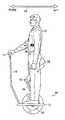
- a subject 10stands on a support platform 12 and holds a grip 14 on a handle 16 attached to the platform 12 , so that the vehicle 18 of this embodiment may be operated in a manner analogous to a scooter.
- a control loopmay be provided so that leaning of the subject results in leaning of the platform which, in turn, results in the application of torque to wheel 20 about axle 22 thereby causing an acceleration of the vehicle.
- Vehicle 18is statically unstable, and, absent operation of the control loop to maintain dynamic stability, subject 10 will no longer be supported in a standing position and can fall from platform 12 .
- FIG. 1BAnother prior art balancing vehicle is shown in FIG. 1B and designated generally by numeral 24 .
- Personal vehicle 24shares the characteristics of vehicle 18 of FIG. 1A , namely a support platform 12 for supporting subject 10 and grip 14 on handle 16 attached to platform 12 , so that the vehicle 24 of this embodiment may also be operated in a manner analogous to a scooter.
- FIG. 1Bshows that while vehicle 24 may have clusters 26 each having a plurality of wheels 28 , vehicle 24 remains statically unstable and, absent operation of a control loop to maintain dynamic stability, subject 10 will no longer be supported in a standing position and may fall from platform 12 .
- a standing rider 10 of the vehicle 30places his feet on the platform and shifts weight back and forth in a relatively wide and flat path 33 .
- the slight amount of strength that is needed to resist gravity and inertia in transversing this arcis well within the strength and coordination of an average user's muscles.
- the center of gravity of the vehicle and rider 35moves in an arcuate fashion as the rider leans either forward or backward.
- movement of the center of gravity in the manner described abovemay no longer be possible and an alternative mechanism for shifting the center of gravity is required.
- the mechanismneeds to provide adequate range of motion while allowing the rider to resist gravity and inertia.
- the inventionin one aspect, features a vehicle for transporting a payload over a surface.
- the vehicleincludes a support for supporting a payload and an enclosure for at least partially enclosing the payload.
- the vehiclealso includes two laterally disposed ground-contacting elements (e.g., wheels, tracks, rollers, legs) coupled to at least one of the enclosure or the support.
- the vehiclealso includes a drive coupled to the ground-contacting elements.
- the vehiclealso includes a controller coupled to the drive, for governing the operation of the drive at least in response to the position of the center of gravity of the vehicle to dynamically control balancing of the vehicle.
- the drivepropels the ground-contacting elements along the ground.
- the enclosureis coupled to the support.
- the vehicleincludes a structure coupling the support and the enclosure to the ground-contacting elements, the structure allows for variation in the position of the center of gravity. In some embodiments, the position of the center of gravity varies in one or more of the fore-aft, lateral and vertical planes of the vehicle.
- the structureincludes rails allowing the enclosure and support to slide with respect to the ground-contacting elements.
- the structureincludes a pivot mechanism coupling the support and enclosure to the ground-contacting elements allowing the enclosure and support to pivot with respect to the ground-contacting elements.
- the payloadis a human subject and the vehicle includes an input device, the human subject pushes or pulls the input device allowing the human subject, support and enclosure to move with respect to the ground-contacting elements.
- the vehicleincludes one or more (e.g., two) four-bar linkages, each four-bar linkage coupling a ground-contacting element to the support and the enclosure, allowing the enclosure and support to move relative to the ground-contacting elements.
- the enclosureis coupled to the ground-contacting elements.
- the vehicleincludes a structure coupling the support to the enclosure and ground-contacting elements, the structure allows for variation in the position of the center of gravity.
- the structureincludes rails allowing the support to slide (e.g., fore and aft) with respect to the enclosure and the ground-contacting elements.
- the structureincludes a pivot mechanism coupling the support to the enclosure and ground-contacting elements, allowing the support to pivot with respect to the enclosure and ground-contacting elements.
- the vehicleincludes two four-bar linkages, each four-bar linkage coupling the support to the enclosure and the ground-contacting elements, and allowing the support to move relative to the ground-contacting elements.
- the payloadis a human subject and the structure includes an input device, the human subject pushes or pulls relative to the input device allowing the human subject and support to move with respect to the enclosure and ground-contacting elements.
- the vehicleincludes an actuator that controls the position of the center of gravity of one or more of the support, payload or enclosure relative to the ground-contacting elements.
- the vehicleis controlled based on a selected operation mode.
- the operation modeis a remote controlled mode or the payload is a human subject and the operation mode is a human subject controlled mode.
- the payloadis a human subject that applies pressure on a foot member coupled to the vehicle (e.g., platform, support or enclosure) to decelerate the vehicle.
- the human subjectapplies pressure on the foot member coupled to the vehicle to accelerate the vehicle.
- a shift of the position of the center of gravity rearwardcauses a deceleration (e.g., if initially moving forward) of the vehicle.
- a shift of the position of the center of gravity rearwardcauses a rearward acceleration (e.g., if initially stopped or moving rearward) of the vehicle.
- a shift of the position of the center of gravity forwardcauses a forward acceleration of the vehicle.
- a shift of the position of the center of gravity forwardcauses a deceleration of the vehicle when initially traveling rearward.
- the vehicleincludes a stabilizer ground-contacting element positioned on the vehicle to statically stabilize the vehicle (e.g., when not being dynamically stabilized).
- the stabilizer ground-contacting elementis retractable. In some embodiments, the stabilizer ground-contacting element includes a sensor for detecting at least one of the a) stabilizer ground-contacting element contacting the ground or b) force applied between the stabilizer ground-contacting element and the ground. In some embodiments, the stabilizer ground-contacting element includes one or more wheels, skids, balls or posts.
- the vehicleincludes one or more sensors for detecting a change in the position of the center of gravity of the vehicle.
- the one or more sensorsis one or more of a force sensor, position sensor, pitch sensor or pitch rate sensor.
- a start modethat is triggered by a change in the position of the center of gravity of the vehicle, the change in the position of the center of gravity initiating dynamic stabilization of the balancing vehicle such that the vehicle is no longer stabilized by a stabilizer ground-contacting element.
- the stabilizer ground-contacting elementis positioned towards the front of the vehicle and the position of the center of gravity shifts rearward to, for example, trigger a start mode.
- the stabilizer ground-contacting elementis positioned rearward of the vehicle and the position of the center of gravity shifts forward to, for example, trigger a start mode.
- a shift of the position of the center of gravity of the vehicle beyond a thresholdtriggers a stop mode that decelerates the vehicle.
- the payloadis a human subject and the vehicle includes an input device, the input device coupled to the vehicle by a linkage such that the vehicle accelerates forward (or decelerates rearward) when the human subject pushes the input device forward and the vehicle decelerates forward (or accelerates rearward) when the human subject pulls the input device rearward.
- the drivedelivers power to the ground-contacting elements to cause rotation of the ground-contacting elements to dynamically control balancing of the vehicle.
- the driveis a motorized drive.
- the drivemoves the ground-contacting elements fore and aft of the vehicle to dynamically control balancing of the vehicle.
- the vehicleincludes a second drive for delivering power to the ground-contacting elements to propel (e.g., cause rotation of the ground-contacting elements) the vehicle for and aft.
- the vehicleincludes an internal combustion engine, pedal, or crank coupled to the second drive for delivering power to the ground-contacting elements to, for example, cause rotation of the ground-contacting elements to propel the vehicle for and aft
- the inventionin another aspect, features a method for transporting a payload over a surface with a vehicle.
- the methodinvolves supporting a payload with a support and at least partially enclosing the support with an enclosure.
- the methodalso involves controlling operation of a drive in response to position of the center of gravity of the vehicle to dynamically control balancing of the vehicle, wherein the drive is coupled to two laterally disposed ground-contacting elements coupled to at least one of the enclosure or support.
- the delivered poweris in response to attitude (e.g., pitch) of the vehicle.
- the enclosureis coupled to the support and the support and enclosure move relative to the ground-contacting elements to change the position of the center of gravity of the vehicle.
- the enclosureis coupled to the ground-contacting elements and the support moves relative to the enclosure and ground-contacting elements to change the position of the center of gravity of the vehicle.
- the support and enclosureslide relative to the ground-contacting elements.
- the supportslides relative to the enclosure and the ground-contacting elements.
- the support and enclosurepivot relative to the ground-contacting elements. In some embodiments, the support pivots relative to the enclosure and the ground-contacting elements.
- the methodinvolves applying pressure to a foot member coupled to the vehicle to decelerate the vehicle. In some embodiments, the method involves shifting the position of the center of gravity rearward to cause a deceleration of the balancing vehicle. In some embodiments, the method involves shifting the position of the center of gravity forward to cause an acceleration of the balancing vehicle. In some embodiments, the method involves shifting the center of gravity rearward to cause an acceleration of the balancing vehicle. In some embodiments, the method involves stabilizing the balancing vehicle with a stabilizer ground-contacting element positioned on the vehicle. In some embodiments, the method involves retracting the stabilizer ground-contacting element when the vehicle is dynamically balanced.
- the methodinvolves triggering a start mode when a sensor mounted on the vehicle detects a change in the position of the center of gravity shift and initiating dynamic stabilization of the vehicle. In some embodiments, the method involves shifting the position of the center of gravity rearward to initiate dynamic stabilization of the vehicle. In some embodiments, the method involves shifting the position of the center of gravity forward to initiate dynamic stabilization of the vehicle. In some embodiments, the method involves triggering a stop mode of the vehicle by shifting the position of the center of gravity of the vehicle beyond a threshold and decelerating the balancing vehicle.
- the methodinvolves applying pressure to a foot member coupled to at least one of the platform or enclosure to move the position of the center of gravity rearward.
- the relative position of the payload to the ground-contacting elementsis an input to the controller.
- the inputis added to or subtracted from commanded acceleration or deceleration of the vehicle by changing desired pitch of the vehicle and shifting the position of the center of gravity of the vehicle.
- the inputmodifies desired pitch of a speed limiting algorithm used to control speed of the vehicle.
- the methodinvolves delivering power from the drive to the ground-contacting elements to cause rotation of the ground-contacting elements to dynamically control balancing of the vehicle.
- the methodalso involves the drive moves the ground-contacting elements fore and aft of the vehicle to dynamically control balancing of the vehicle.
- the methodincludes delivering power from a second drive to the ground-contacting elements to cause rotation of the ground-contacting elements to move the vehicle fore and aft.
- the inventionin another aspect, features a vehicle for transporting a payload over a surface.
- the vehicleincludes a support for supporting a payload and an enclosure for at least partially enclosing the payload.
- the vehiclealso includes two laterally disposed ground-contacting elements coupled to at least one of the enclosure or the support.
- the vehiclealso includes a drive coupled to the ground-contacting elements.
- the vehiclealso includes means for governing the operation of the drive at least in response to position of the center of gravity and/or tiling of the vehicle to dynamically control balancing of the vehicle.
- the inventionin another aspect, features a vehicle for transporting a payload over a surface.
- the vehicleincludes a support for supporting a payload and an enclosure for at least partially enclosing the payload.
- the vehiclealso includes two laterally disposed ground-contacting elements coupled to at least one of the enclosure or the support.
- the vehiclealso includes a first drive coupled to the ground-contacting elements.
- the vehiclealso includes a controller coupled to the first drive, for governing the operation of the first drive at least in response to the position of the center of gravity of the vehicle to move the ground-contacting elements fore and aft of the vehicle to dynamically control balancing of the vehicle.
- the vehiclealso includes a second drive coupled to the ground-contacting elements to deliver power to the ground-contacting elements to propel the vehicle for and aft.
- the vehicleincludes an internal combustion engine coupled to the second drive for delivering power to the ground-contacting elements.
- the vehicleincludes rails coupled to the ground-contacting elements allowing the first drive to command the ground-contacting elements to move fore and aft of the vehicle to dynamically control balancing of the vehicle.
- the inventionin another aspect, features a method for transporting a payload over a surface with a vehicle.
- the methodinvolves supporting a payload with a support and at least partially enclosing the support with an enclosure.
- the methodalso involves controlling operation of a first drive, coupled to at least one of the enclosure or support, in response to position of the center of gravity of the vehicle to move the ground-contacting elements fore and aft of the vehicle to dynamically control balancing of the vehicle.
- the methodalso involves controlling operation of a second drive coupled to the two laterally disposed ground-contacting elements to deliver power to the ground-contacting elements to propel the vehicle fore and aft.
- the inventionin another aspect, features a device for transporting a human subject over a surface.
- the deviceis a dynamically balancing vehicle having a control loop for providing balance.
- the deviceincludes a platform defining a fore-aft plane.
- the platformsupports a payload including the human subject.
- a ground-contacting moduleis included which may be one or more wheels.
- the ground-contacting memberis movably coupled to the platform.
- the device and any load on the devicehave a center of gravity that is defined with respect to the ground-contacting member.
- the devicefurther includes a support.
- the supportmay be a seat for supporting the subject and the support is coupled to the platform in such a manner as to permit variation of the position of the center of gravity in the fore-aft plane by translation and rotation of at least a portion of the support.
- the translation and rotation of at least a portion of the supportare mechanically coupled in one embodiment.
- the transportation devicefurther includes a drive which is coupled to the ground-contacting module and which delivers power to the ground-contacting module in a manner responsive to the position of the center of gravity.
- the drivesupplies force so as to balance the vehicle.
- the supportrotates about a virtual pivot point which lies above the support. The structure of the support allows the support to rock about an arc or other path.
- the supportmay include a mechanical linkage such as a four-bar linkage.
- each bar of the four-bar linkageis coupled together with pivots.
- a structuree.g., a fifth bar
- the structureis attached at one of the pivots of the four-bar linkage.
- the structureis attached to one of the bars of the four-bar linkage.
- the four-bar linkageforms a parallelogram and changes shape as a user of the vehicle moves on the seat shifting the center of gravity.
- the deviceincludes pressure sensors for activating the drive and causing the control loop to become active when the driver or payload is present.
- the pressure sensorsmay be placed in the platform for activation or the pressure sensors may be placed in the seat.
- a mechanical contactis attached to the support which contacts the pressure sensors that are coupled to the platform.
- the supportincludes a seat that is slideably mounted.
- the supportincludes one or more rails for allowing the seat to slide.
- the seatneed not be capable of rotation about a pitch axis of the vehicle in such an embodiment, but does allow for the user to change the center of gravity for controlling the vehicle.
- the sliding seatdoes rotate about the pitch axis of the vehicle.
- the railsinclude one or more sprockets that engage with protrusions that are coupled to the seat and thus cause rotation as the seat is rolled on the rails.
- the supportmay include one or more pulleys that assist the seat in sliding along the one or more rails.
- the seatis coupled to friction wheels that ride on a friction surface.
- the supportincludes a convex radial base that allows the support to rock in response to a user shifting his weight.
- the convex radial basemay be coupled to the platform at a pivot point that translates fore and aft with the motion of the seat.
- the convex radial basemay have different radii of curvature along its convex surface.
- the supportmay include a damper to resist motion of the slide and damp unwanted control system oscillations.
- the supportpreferably returns to a position, such that the vehicle remains substantially stationary when no force is applied to the support. In such an embodiment, the vehicle may still move slightly as the control loop balances the vehicle.
- a controlleris either coupled to the drive or part of the drive and the controller is part of a control loop which is responsive to changes in the tilt angle of the vehicle.
- the seatmay be coupled to the platform by a universal pivot. In another embodiment, the seat is coupled to a control stalk.
- FIG. 1Ais a side view of a prior art dynamically balancing vehicle of the type of which an embodiment of the invention may be advantageously employed.
- FIG. 1Bis a side view of a further prior art dynamically balancing vehicle of the type of which an embodiment of the invention may be advantageously employed.
- FIGS. 2A and 2Bare a prior art dynamically balancing vehicle having a platform that rotates in an arc.
- FIG. 3shows a dynamically balancing vehicle having a seat.
- FIG. 3Ashows a dynamically balancing vehicle in which the seat is coupled to a control stalk.
- FIG. 3Bshows a dynamically balancing vehicle in which the seat is coupled to the platform by a pivot.
- FIG. 3Cshows a dynamically balancing vehicle in which the seat is slideably mounted.
- FIG. 3Dshows a dynamically balancing vehicle having a seat.
- FIG. 4Ashows the seat of the dynamically balancing vehicle mounted on a four-bar linkage.
- FIG. 4Bshows one position of the four-bar linkage as would occur if a rider leaned backwards shifting the center of gravity in the aft direction.
- FIG. 4Cshows that the four-bar linkage simulates a rocking motion such that there is translation and rotation of the seat.
- FIG. 4Dshows the center of gravity translating in a straight line while the seat both translates and rotates.
- FIG. 4Eshows a bar linkage mechanism for translation and rotation wherein one or more bars are flexible.
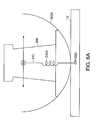
- FIG. 5Ais an embodiment of the dynamically balancing vehicle in which the seat is attached to a bar via a pivot.
- FIG. 5Bis an embodiment that shows the seat attached to a slider about a pivot point wherein pulleys help to control rotation.
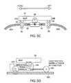
- FIG. 5Cshows a seat that is coupled to a slider that rides on at least partially curved rails.
- FIG. 5Dshows a seat coupled to a track which includes friction wheels wherein the seat both translates and rotates.
- FIG. 5Eshows a support structure having a plurality of pins which will engage with recesses in the platform.
- FIG. 6shows a side view of an embodiment of the dynamically balancing vehicle with a detachable rocker seat.
- FIG. 6Ashows the support structure attached to the platform via a simple cable under tension.
- FIG. 6Bshows the support structure including a series of teeth on the bottom arced surface and also on the platform.
- FIG. 6Cshows the support structure coupled to the platform about a pivot point.
- FIG. 7Ashows a folding seat which can be attached to a dynamically balancing vehicle wherein the seat is positioned as if a rider is sitting on the seat.
- FIG. 7Bshows a rider sitting on the folding seat.
- FIG. 7Cshows the position of the folding seat when a rider engages/disengages with the vehicle.
- FIG. 7Dshows an embodiment of a dynamically balancing vehicle having knee supports.
- FIGS. 8 and 8Ashow an embodiment of a support structure which includes both translational and rotational mechanical actuators.
- FIG. 9is a three-dimensional view of a vehicle, according to an illustrative embodiment of the invention.
- FIG. 10is a block diagram of a control system for dynamically controlling the stability of a vehicle, according to an illustrative embodiment of the invention.
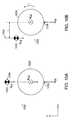
- FIG. 10Ais a block diagram of position of the center of gravity of a vehicle with respect to a ground-contacting element of the vehicle.
- FIG. 10Bis a block diagram of an alternative position of the center of gravity of the vehicle of FIG. 10A with respect to a ground-contacting element of the vehicle.
- FIG. 11Ais a schematic illustration of a vehicle, according to an illustrative embodiment of the invention.
- FIG. 11Bis a schematic illustration of a vehicle, according to an illustrative embodiment of the invention.
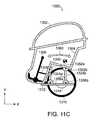
- FIG. 11Cis a schematic illustration of a vehicle, according to an illustrative embodiment of the invention.
- FIG. 11Dis a schematic illustration of a vehicle, according to an illustrative embodiment of the invention.
- FIG. 12Ais a schematic illustration of a vehicle, according to an illustrative embodiment of the invention.
- FIG. 12Bis a schematic illustration of a vehicle, according to an illustrative embodiment of the invention.
- FIG. 12Cis a schematic illustration of a vehicle, according to an illustrative embodiment of the invention.
- FIG. 12Dis a schematic illustration of a vehicle, according to an illustrative embodiment of the invention.
- FIG. 13Ais a three-dimensional view of a vehicle, in accordance with an embodiment of the invention.
- FIG. 13Bis an alternative configuration of the vehicle of FIG. 13A .
- FIG. 14is a schematic illustration of a vehicle, according to an illustrative embodiment of the invention.
- the balancing vehicleincludes a ground-contacting module 32 which, in the embodiment that is shown, is a pair of co-axial wheels powered by motors.
- a controlleris coupled to the motor for providing a control signal in response to changes in the center of gravity of an assembly that includes the vehicle along with a rider.
- the controller modulesenses the change in the center of gravity 36 and controls power to the wheels 32 based upon changes to the center of gravity 36 about a fore-aft plane 42 using a control loop. As the center of gravity 36 moves forward in the fore direction, power is provided to the wheels and the vehicle will move forward.
- the vehiclewill slow and reverse direction such that the vehicle moves in the aft direction.
- torqueis applied to one or more the wheels (or other ground-contacting members) of the vehicle by operation of the control loop and a wheel actuator (not shown).
- the pitch of the vehiclemay also be sensed and compensated for in the control loop.
- the control moduleincludes gyroscopes for sensing changes in the position of the center of gravity.
- the vehicle that is shownincludes a platform 12 for supporting the rider and a control stalk 14 and 16 .
- Appropriate force transducersmay be provided to sense leftward and rightward leaning and related controls provided to cause left and right turning as a result of the sensed leaning.
- the leaningmay also be detected using proximity sensors.
- the vehicle of this embodimentmay be equipped with a foot- (or force-) actuated switch located on the platform 12 to activate the vehicle, in such a manner that the switch is closed so as to power the vehicle automatically when the subject contacts the platform 12 .
- This embodimentfurther includes a support 34 , 38 , 40 for the rider; the support may include a seat 34 on which the rider can rest.
- the seat 34is attached to the control stalk 16 as shown in FIG. 3A .
- the rider 10then uses his body and momentum to move the center of gravity of the combination of the vehicle and the rider in either a forward or in an aft direction.
- the seat 34is attached to the platform 12 via a pivot point 44 as shown in FIG. 3B .
- the pivotmay be a simple pivot such that the pivot moves only in the fore and aft directions or the pivot may be a universal pivot so that the seat may pivot in any direction.
- a universal pivotis a spring.
- the pivotmay be mounted to the platform along the axis of the wheels, or the pivot may be mounted at other locations such as along the rear edge of the platform.
- a seatis attached to the platform using one or more rails 46 on which the seat 34 slides as shown in FIG. 3C .
- the movement of the seat 34 by the ridercauses a change in the position of the center of gravity of the vehicle and its load. If the seat is moved in the fore direction sensors sense the resulting tilt of the vehicle and cause the vehicle to increase in speed in the fore direction. If the seat is slid in the aft direction, the vehicle 30 will slow down correspondingly.
- a centering mechanismsuch as, a spring may be incorporated with either the pivot or sliding seat, so the seat will return to a position such that the vehicle is substantially stationary when a rider disengages from the vehicle.
- a seat 50is mounted to the platform 12 .
- the seat and the linkage 52 to the platformdo not include a pivot.
- the seat in this embodimentpreferably extends the length of the platform.
- the vehicleincludes a bar linkage mechanism, such as a four-bar linkage, that is attached to the control stalk as shown in FIG. 4A .
- the four-bar linkage mechanismis also attached to a seat by another bar (seat post) which is coupled to the four-bar linkage about a common pivot point of the four-bar linkage or coupled to a bar in the linkage.
- the four-bar linkage mechanismallows the seat to move in an arc which simulates a rocking motion similar to that of a rocking chair about the base platform as shown in FIG. 4C .
- FIG. 4Bshows one position of the four-bar linkage 55 as would occur if a rider leaned backwards shifting the center of gravity in the aft direction.
- the riderboth moves in the aft direction and also rotates in the aft direction and as such both, translation and rotation are coupled together.
- the four-bar linkageallows the seat to move in an arc about a virtual pivot point.
- the virtual pivot pointcan be located at a point above the seat. In other embodiments, the virtual pivot point may be located below the seat.
- the seat 34both translates and rotates the center of gravity 35 moves in a straight line in the fore-aft plane as shown in FIG. 4D .
- the center of gravityneed not move in a straight line and the position of the center of gravity may vary.
- the motion of the seatcreates a rider experience that is different from the seats discussed above in FIGS. 3A-3D .
- no arm forceis required to maintain a position of the center of gravity relative to the wheel axis as is the case with simple and universal pivots as shown in FIGS. 3A-3C .
- Thisallows both ease of pitch control and the ability of the rider to find the center of gravity position above the axle of the vehicle so that the vehicle is substantially stationary.
- the virtual pivot mechanismallows the seated rider, to have a similar experience on the dynamically balancing vehicle that a standing rider would have.
- control stalkis held by the rider by a pair of hand grips that extend from the control stalk.
- the seatcan move about the fore-aft plane and the seat will both shift and rotate when the rider moves, thus changing the center of gravity.
- FIGS. 5A-E and FIGS. 6 , 6 A, 6 B, and 6 C and the present inventionare not intended to be limited to mechanical linkages.
- the four-bar linkageincludes non-rigid members that can flex.
- FIG. 4Eshows a support structure where members B and C each flex and member D is rigid as are the couplings of members B and C to platform A.
- members B and Care shown such that the two members lean inwards to meet member D.
- the members B and Cwill flex such that the seat will move in a rocking motion about a virtual pivot point that lies above the seat.
- the motion of members B and Cis shown in FIG. 4E by the dotted lines. As such, member D which supports the seat will both translate and rotate.
- pivotsmay be included in such an embodiment, so that the linkage both pivots and flexes.
- pivotsmay be placed at the point where member D comes into contact with members B and C as shown in the figure.
- members B and Cmay be positioned so rather than leaning inward, the two members are outward leaning.
- the seatwill move much like a rocking chair. If a rider leans in the fore direction the seat will translate in the fore direction and the seat will rotate such that the fore-most part of the seat will be lower than the aft-most part of the seat. This is different from the embodiment that is shown in FIG. 4E wherein if a rider causes the seat to translate in the fore direction, the seat will rotate such that the fore-most part of the seat is elevated as compared to the aft- most part of the seat.
- FIGS. 5A-5Eeach show different embodiments in which both translation and rotation are coupled.
- the seat 34is attached to a bar 58 via a pivot 60 .
- the seatfurther includes a series of protrusions 62 formed in an arc which mesh with a sprocket 64 .
- the sprocket 64is attached to the bar 58 and can spin about an axis 66 .
- the barincludes a second sprocket 67 which can rotate about a central axis 69 .
- the sprockets 64 , 67each reside on a strip/track 70 that includes protrusions 72 that mesh with the sprockets 64 , 67 .
- the track on which the seat slidesmay have a different profile.
- the trackmay be convex, concave, or have a varying profile along its length. If the track has a varying profile, the rider needs to apply more force to move the seat along certain portions of the track.
- different track profilesmay be employed in order to shape the path of the center of gravity and the center of gravity need not move in a straight line.
- the seat 34attaches to a slider 75 about a pivot point 76 .
- the sliderfits on a rail 78 and the slider 75 can slide on the rail 78 .
- Attached to the slider at the seatare at least two pulleys 79 , 80 .
- the pulleys 79 , 80are positioned toward opposite ends of the seat about the slider.
- One or more wires or cables 81are attached to the seat and a fixed portion of the vehicle such as the rail. The cables 81 engage the pulleys 80 , 79 .
- the pulleyscause the seat to tilt due to changing tension in the cables.
- the cablesare coupled to either end of the rail 85 , 86 or some other component of the vehicle and also to the seat at opposite ends 83 , 84 .
- there are two separate cablesone of which runs from rail end 86 across pulley 79 and attaches to the seat at 84 .
- the second cableattaches to the seat at 83 and across pulley 80 and attaches at the rail end 85 . If the seat is moved in the aft direction, the edge of the seat in the aft direction will be rotated and lowered. Similarly, if the seat is moved by the rider in the fore direction, the fore-most part of the seat will rotate and will be lowered.
- the seatis coupled to a slider 87 about a pivot point 88 .
- the slider 87is seated on a rail 89 and provides for the seat to be slid in a fore and an aft direction.
- the seatalso includes two extensions 34 A, 34 B that each have two wheels 90 mounted thereto. Between each pair of wheels is a straight track which includes an arc 89 A, 89 B at each end of the track.
- the wheelsroll along the arc and cause the seat to tilt about the pivot point
- the trackhas a varying curvature, such that the center portion of the track is itself curved and that the ends have a greater radius of curvature as compared to the center.
- the seat 34rides on a track 200 .
- the seat 34is coupled to a transmission 210 by a pivot 220 .
- the transmissionis coupled to a pair of friction wheels 225 , 230 .
- translation of the seat 34is directly coupled to rotation of the seat.
- the wheelsrotate a greater amount than the pivot rotates the seat.
- the transmissiontherefore, causes the seat to pivot/rotate at a fraction of the rotation of the friction wheels. It should be understood that all of the tracks that are shown in FIGS.
- the support structurealso will include a mechanism for holding the track at a proper seat height.
- the trackmay be mounted to the control stalk, or may sit on its own mounting structure that is coupled to the platform.
- the mounting structuremay be a shaft.
- FIG. 6shows a side view of an embodiment of the dynamically balancing vehicle with a detachable rocker seat.
- the rocker seatincludes a support structure 95 .
- the bottom portion of the support structurecontacts the platform and is shaped like an arc 97 allowing the seat 34 to rock.
- the arc shaped lower member 97 of the support structure 95is coupled to the platform 12 via a moving contact point.
- the arc shaped member 97 memberrotates equally in the fore and aft plane in this embodiment. Although in other embodiments, rotation may be limited in either the fore or aft direction.
- the support structuremay also be coupled to the platform via a pair of rails.
- the support structurerests on the rails that the rails include a mechanism that constrains the support structure from moving in any other plane other than the fore-aft plane.
- the arch shaped lower portion of the support structureis not coupled to the platform at a contact point.
- the arc shaped membermay roll on a series of rails or wheels.
- the support structuremay include a guide pin that extends through the support structure and is enclosed by the rails on either side of the support structure.
- the seatcan rock in the fore-aft direction about a virtual pivot that is above the seat. It should be understood that a virtual pivot point need not be above the seat, in certain embodiments, the virtual pivot point may exist below the seat, for example.
- the lower surface of the support structure that is formed in an arcmay have any number of radii.
- the lower surfacemay have a greater curvature at the edges and less of a curvature at its center, so that as the support structure rocks about its central portion, each unit of translation there is proportional to a degree of rotation, but as the support structure is rocked further toward the edges, there is a greater degree of rotation for each unit of translation.
- the lower surface of the support structure 150includes two pins 160 , 165 at the edges of the arc as shown in FIG. 5E .
- the support structurerocks 170 to the edge, one of the pins 160 or 165 will engage with a recess 160 A or 165 A in the platform 12 . If the rider continues to lean in the same direction, the support structure will rotate about the pin 160 or 165 .
- FIG. 6in which the support structure has an arc as the lower surface, may be coupled to the platform in any one of a number of ways.
- gravitymay hold the support structure on the platform 12 .
- the platform surface and the bottom surface of the support structuremay be formed from materials having a high coefficient of friction.
- the support structure 300may be attached to the platform 12 via a simple cable 310 under tension (including a spring 310 A).
- the spring 310 Astretches, and thus there is a restoring force returning the support structure 300 to a centered position as shown.
- FIG. 6Athe support structure 300 may be attached to the platform 12 via a simple cable 310 under tension (including a spring 310 A).
- the support structure 400may include a series of teeth 410 on the bottom arced surface 400 A and the platform 12 may include a series of mating teeth 420 for the bottom surface. As the support structure rocks the teeth of the bottom surface and of the platform interlock.
- the support structure 500is coupled to the platform 12 about a pivot point 510 .
- the pivot 510is coupled to a member 520 which extends down through the platform and which in this embodiment, rides on a pair of wheels 530 .
- the member 520is rigid.
- the support structure 500will translate and the wheels 530 will rotate on the bottom side of the platform as shown.
- the support structure 500will also rotate about the pivot point 510 due to the arched bottom side of the support structure 500 A.
- the support structure 500will maintain contact with the platform at all times, including over rough terrain.
- the platform of the vehicleincludes one or more pressure sensors to sense the rider either engaging or disengaging from the vehicle.
- the riderpowers-up the vehicle and engages the vehicle, the vehicle enters a balancing mode.
- a control loopis made operational that senses changes to the position of the center of gravity and that causes the vehicle to move with respect to the changes. If the vehicle includes a seat, the rider may not engage the pressure sensors because her feet may not make contact with the platform or the rider may remove her feet from the platform.
- sensorssuch as pressure sensors, may be included in the seat.
- a mechanical devicesuch as a link or tube may be employed to make contact with the platform when the rider engages the vehicle.
- FIGS. 7A-Cshows a folding seat which may be employed with the previously described vehicles.
- the seatIn FIG. 7A the seat is in full view and is positioned as if a rider is sitting on the seat. The sides of the seat expand in an outward direction like an accordion when weight is put on the seat.
- FIG. 7Bshows a rider sitting on the seat.
- FIG. 7Cshows the position of the seat when a rider 10 engages/disengages with the vehicle. If the rider is already on the vehicle, the seat 34 rises up and folds as the rider stands and the support structure 92 contracts inwardly reducing the size of the support.
- the support structure for the seatmay also include a mechanism for allowing lateral movement in a plane substantially perpendicular to the fore-aft plane of the vehicle.
- the vehiclemay include sensors to sense the lateral movement.
- the sensorscan be tied into a control loop so that if a rider leans to the right more power is applied to the left wheel allowing the vehicle to turn to the right.
- lateral movementmay not be tied to sensors and a control loop, but may simply perform the function of allowing the rider to readily shift his or her weight of over rough terrain.
- the support structuremay also include knee rests 290 as shown in FIG. 7D to allow more consistent rider coupling to the vehicle and to provide postural advantage and/or partial body support.
- FIG. 8shows another embodiment, in which the seat 34 both translates and rotates. It is preferable that translation and rotation are coupled.
- the force sensors 120sense the change.
- both a linear actuator 125 and a rotational actuator 130are engaged. If the rider shifts his weight such that more weight is provided to force sensor A than to B, the linear actuator 125 will cause translation of the seat in the fore direction. Additionally, the seat will be rotated in the fore direction by the rotational actuator 130 , such that the fore-most part of the seat will be lowered and the aft-most part of the seat will be raised.
- the embodiment as shownalso includes a linear actuator 135 that provides linear motion in the vertical direction.
- This actuator 135makes engagement and disengagement with the vehicle easier.
- both translation and rotationare controlled by mechanical actuators.
- mechanical actuatorsfor providing translation and rotation of the seat, assists individuals having a reduced strength capacity when compared to the simpler mechanical designs that require the rider to manually shift the position of the seat, to significantly shift their weight using their own strength, and to maintain a position of either leaning in the fore or in the aft direction using their muscle strength.
- FIG. 9is a three-dimensional view of a vehicle 1100 , according to an illustrative embodiment of the present invention.
- a human subjectrests on a support 1102 in an enclosure 1104 that at least partially encloses the human subject.
- the vehicle 1100includes at least two ground-contacting elements 1108 , 1110 .
- the two ground-contacting elements 1108 , 1110are coupled to a platform 1106 .
- the ground-contacting element 1108is laterally disposed to the ground-contacting element 1110 .
- the ground-contacting elementseach rotate about an axle 1114 and are powered by at least one drive 1116 (e.g., a motorized drive).
- a controller( 1160 ) is coupled to the drive 1116 for providing a control signal in response to changes in vehicle orientation (e.g., pitch) and position of the center of gravity 1112 of the vehicle 1100 .
- ground-contacting elements 1108 and 1110are wheels in this embodiment of the invention.
- ground-contacting elementse.g., ground-contacting elements 1108 and 1110
- one or more ground- contacting elements of a vehicleare a track, roller, ball, arcuate element or leg.
- the controller 1160implements a control loop and senses a change in the vehicle's 1100 orientation that can result from a change in the position of the center of gravity 1112 in a fore-aft plane and controls power provided to the ground-contacting elements 1108 , 1110 based upon the change to the position of the center of gravity 1112 .
- torqueis applied to the ground-contacting elements 1108 , 1110 to dynamically stabilize the vehicle 1100 .
- the drive 1116provides power to the two ground-contacting elements 1108 , 1110 sufficient to cause the vehicle 1100 to move forward (toward the negative X-Axis direction).
- the drive 1116provides power to the two ground-contacting elements 1108 , 1110 sufficient to cause the vehicle 1100 to slow and reverse direction such that the vehicle 1100 moves backward (toward the positive X-Axis direction).
- the drive component 1116provides power to the two ground-contacting elements 1108 , 1110 sufficient to cause the vehicle 1100 to turn left or right. More power can be applied to the left ground-contacting element to turn right. In some embodiments, less power is provided to the right ground-contacting element to turn right. In some embodiments, more power is provided to the left ground-contacting element and less power is provided to the right ground-contacting element to turn right.
- the pitch of the vehicle 1100may also be sensed and compensated for in the control loop.
- the controllerincludes gyroscopes for sensing orientation of the vehicle 1100 that can result from changes in the position of the center of gravity 1112 .
- Appropriate force transducersmay be provided to sense leftward and rightward leaning and related controls provided to cause left and right turning as a result of the sensed leaning.
- the leaningmay also be detected using proximity sensors.
- the vehicle of this embodimentmay be equipped with a foot- (or force-) actuated switch located on, for example, the platform 1106 or support 1102 to activate the vehicle 1100 , in such a manner that the switch is closed so as to power the vehicle 1100 automatically when the subject contacts the platform 1106 .
- a foot- (or force-) actuated switchlocated on, for example, the platform 1106 or support 1102 to activate the vehicle 1100 , in such a manner that the switch is closed so as to power the vehicle 1100 automatically when the subject contacts the platform 1106 .
- the drive 1116provides power to the two ground-contacting elements 1108 , 1110 sufficient to cause the vehicle 1100 to move backward (toward the positive X-Axis direction).
- the drive 1116provides power to the two ground-contacting elements 1108 , 1110 sufficient to cause the vehicle 1100 to slow down and reverse direction such that the vehicle 1100 moves forward (toward the negative X-Axis direction).
- Vehicle 1100 pitch variationis decreased during operation when the vehicle 1100 is dynamically stabilized based on the change in the position of the center of gravity 1112 rather than in response to a change in pitch. It also shortens the time it takes the vehicle 1100 to respond to an acceleration and/or deceleration command. The vehicle 1100 accelerates and/or decelerates by restoring the position of the center of gravity 1112 of the vehicle 1100 over the location that the ground-contacting elements 1108 and 1110 contact the ground.
- a controller of the vehicle 1100would first need to induce a change in the position of the center of gravity 1112 relative to a steady state position and then command the drive 1116 to operate the ground-contacting elements 1108 and 1110 in such a manner as to position the center of gravity 1112 above the location where the ground-contacting elements contact the ground.
- the time required to induce a change in the position of the center of gravity 1112 back to the steady state positionis a time delay for the vehicle 1100 to respond to an acceleration and/or deceleration command compared to acceleration and/or deceleration in response to a change in the position of the center of gravity.
- the vehicle 1100does not need to induce the change in the position of the center of gravity 1112 from a steady state because the change of the position of the center of gravity 1112 is inherit in the acceleration and/or deceleration command.
- the acceleration and/or deceleration commandnecessitates a change in the orientation of the vehicle 1100 to position the center of gravity 1112 in the correct position so that acceleration and/or deceleration can begin.
- FIG. 10is a block diagram of a control system 1200 for dynamically controlling the stability of a vehicle (e.g., vehicle 1100 as discussed above in FIG. 9 ), according to an illustrative embodiment of the invention.
- a controller 1202receives an input characteristic of a position of a center of gravity of a vehicle (e.g., center of gravity 1112 as discussed above in FIG. 9 ) from a sensor module 1204 . Based on at least the position of the center of gravity provided by the sensor module 1204 , the controller 1202 commands torque T of at least one of the left motorized drive 1206 or right motorized drive 1208 (e.g., torque applied to the corresponding ground contact elements).
- FIGS. 10A and 10Bare block diagrams that illustrate the effect of the position of the center of gravity 1222 of a vehicle 1230 on operation of the vehicle 1230 , according to an illustrative embodiment of the invention.
- the vehicle 1230has a total mass M 2 (weight of M 2 g).
- the mass of a payload and a portion of the vehicle 1230is denoted as M 1 (weight of M 1 g) which corresponds to the mass of the center of gravity 1222 .
- the mass of two laterally disposed contacting elements 1220is denoted as mass M 0 (weight of M 0 g).
- the portion of the vehicle 1230 capable of moving along the X-Axis direction relative to the position of the ground-contacting elements 1220is represented by the center of gravity 1222 .
- the center of gravity 1222is located at an initial location 1234 above the location 1238 where the ground-contacting elements 1220 contact the ground.
- the center of gravity 1222is located at a location 1242 , at a distance L along the negative X-Axis direction relative to the initial location 1234 .
- the center of gravity 1222is positioned at location 1242 by a human subject moving the position of the center of gravity of the vehicle 1230 (e.g., similarly as described herein with respect to, for example, FIG. 9 ).
- the sensor module 1204(of FIG. 10 ) provides the pitch of the vehicle 1230 and the orientation of the vehicle 1230 , that change as the position 1242 of the center of gravity 1222 changes, to the controller 1202 .
- the masses of the vehicle 1230can be advantageously distributed between the payload and related structure (collectively 1222 ) and the ground contacting-elements and related structure (collectively 1220 ) to maximize acceleration and deceleration performance.
- the controller 1202also interfaces with a user interface 1210 and a wheel rotation sensor 1212 .
- the user interface 1210can, for example, include controls for turning the vehicle on or off, or for triggering different operating modes of the vehicle (e.g., the operating modes described with respect to FIGS. 13A and 13B ).
- the sensor module 1204detects one or more vehicle parameters to determine a change in the position of the center of gravity of the vehicle. In one embodiment, the sensor module 1204 generates a signal indicative of a change in the position of the center of gravity at one instance in time with respect to the position of the center of gravity at another instance in time.
- a distance sensor attached to a spring, a load sensor, an inclinometer, a gyroscope, whiskers and/or an angular rate sensorcan be used to determine a change in the center of gravity of the vehicle.
- Other sensorse.g., optical sensors and/or magnetic sensors
- the controller 1202includes a control algorithm to determine the amount of torque to be applied by the left motorized drive 1206 and/or right motorized drive 1210 based on the position of the center of gravity.
- the control algorithmcan be configured, for example, during the design of the vehicle or in real time, on the basis of a current operating mode of the vehicle, operating conditions experience by the vehicle, as well as preferences of a human subject.
- the controller 1202can implement the control algorithm for example, by using a control loop.
- the operation of control loopsis well known in the art of electromechanical engineering and is outlined, for example, in Fraser & Milne, Electro-Mechanical Engineering, IEEE Press (1994), particularly in Chapter 11, “Principles of Continuous Control” which is incorporated herein by reference.
- the position of the center of gravity, Ccan be in the form of an error term defined as the desired position of the center of gravity minus the sensed position of the center of gravity.
- the desired position of the center of gravitycan be for example, a predetermined constant in the control algorithm.
- a human subject in the vehiclecan set the position of the center of gravity via a user interface.
- a human subjectupon starting the vehicle and prior to allowing movement of the vehicle, a human subject can activate a switch on the vehicle that triggers determination of the desired position of the center of gravity based on inputs received from the sensor module. This allows the human subject to acquire a known initial position of the center of gravity, from which the human subject can then deviate so as to cause a change in the position of the center of gravity.
- the gain, Kcan be a predetermined constant, or can be entered or adjusted by the human subject through the user interface 1210 .
- Gain Kis, most generally, a vector, with the torque determined as a scalar product of the gain and the position of the center of gravity displacement vector. Responsiveness of the vehicle to changes in the position of the center of gravity can be governed by K. For example, increasing the magnitude of at least one element of vector K causes a human subject to perceive a stiffer response in that a small change in the position of the center of gravity results in a large torque command.
- Offset, Ocan be incorporated into the control algorithm to govern the torque applied to the left motorized drive 1206 and right motorized drives 1208 , either in addition to, or separate from, the direct effect of C.
- the human subjectcan provide an input by means of the user interface 1210 , the input is treated by the controller 1202 equivalently to a change, for example, in the position of the center of gravity.
- steeringcan be accomplished by calculating the torque desired for the left motorized drive 1206 and the torque desired for the right motorized drive 1208 separately. Additionally, tracking both left wheel motion and the right wheel motion permits adjustments to be made, as known to persons of ordinary skill in the control arts, to prevent unwanted turning of the vehicle and to account for performance variations between the left motorized drive 1206 and the right motorized drive 1208 .
- a change in the position of the center of gravityis sensed in the fore-aft plane and/or the lateral plane. Sensing a change in the position of the center of gravity in the lateral plane ensures stability with respect to tipping in the lateral plane.
- lateral changes in the position of the center of gravityare used to trigger anti-tipping mechanisms or otherwise modify the operation of the vehicles performance (e.g., altering the torque applied to one or more ground-contacting elements).
- lateral changes in the position of the center of gravityare used to command the vehicle to turn left or right.
- Steeringmay be accomplished in an embodiment having at least two laterally disposed ground-contacting elements (e.g., a left and right wheel), by providing, for example, separate motors for left and right ground-contacting elements. Torque desired for the left motor and the torque desired from the right motor can be calculated separately. Additionally, tracking both the left ground-contacting element motion and the right ground-contacting element motion with the ground-contacting element rotation sensors 1212 permits adjustments to be made, as known to persons of ordinary skill in the control arts, to prevent unwanted turning of the vehicle and to account for performance variations between the two motors. In some embodiments, steering sensitivity is adjusted to a higher sensitivity when a vehicle is at lower speeds and lower sensitivity when a vehicle is at higher speeds to allow, for example, easier steering at higher speeds.
- ground-contacting elementse.g., a left and right wheel
- control system 1200limits the speed of a vehicle (e.g., vehicle 100 as discussed above in FIG. 9 ).
- the speed limitcan be set based on, for example, a maximum speed associated with the operating mode of the vehicle (for example, as discussed below in connection with FIG. 13A and FIG. 13B ) or an input from the human subject.
- the control system 1200includes a speed limiting algorithm that regulates the speed of the vehicle by controlling the pitch of the vehicle.
- the controller 1202changes the pitch of the vehicle which moves the position of the center of gravity. Changes in the position of the center of gravity causes the vehicle to accelerate or decelerate depending on which direction the center of gravity is moved.
- the speed limiting algorithmcauses the controller 1202 to accelerate or decelerate the vehicle by adjusting a desired pitch angle ⁇ D .
- the pitch control loop of the system 1200controls the system 1200 to achieve the desired pitch angle ⁇ D .
- the adjustment of the desired pitch angle ⁇ Dis determined based on the following relationship:
- ⁇ DK ⁇ ⁇ 1 ⁇ [ K ⁇ ⁇ 2 ⁇ ( V SpeedLimit - V cm ) ⁇ A + K ⁇ ⁇ 3 ⁇ ( IntegratedSpeedError ) ⁇ B + K ⁇ ⁇ 4 ⁇ ( Acceleration ) ⁇ C ] ( EQN .
- V SpeedLimitis the current maximum speed of the vehicle
- V cmis the speed of the vehicle
- K2is a gain proportional to the difference between the vehicle's speed limit and the vehicle's actual speed
- K3is a gain on the Integrated Speed Error, which is the integrated difference between the vehicle's speed limit and the vehicle's actual speed
- K4is a gain on the acceleration of the vehicle
- K1is a gain on the overall calculated desired pitch that can be a function of for example, a position of the center of gravity of the vehicle
- ⁇ Dis the desired pitch angle.
- the cumulative effect of terms A, B and C in EQN. 3is to cause the vehicle to pitch backward into a deceleration orientation if the speed limit is exceeded.
- the value of the desired pitch angle, ⁇ Dis varied in the control system 1200 to control the speed of the vehicle.
- the desired pitch angle ⁇ Dremains constant (e.g., the vehicle remains level with respect to the ground plane).
- the control system 1200responds by setting the desired pitch angle ⁇ D to a value to decelerate the vehicle to prevent the vehicle from exceeding the maximum speed limit. This has the effect of the control system 1200 commanding the vehicle to pitch backwards which causes the speed of the vehicle to decrease.
- the control system 1200is configured to account for the human subject commanding the vehicle to slow down.
- the controllerreduces the value of the gain K1.
- the pitch angle terms in the control system 1200(governed by, for example, EQN. 3) are de-emphasized. Because the control system 1200 de-emphasizes the pitch angle terms, the control system 1200 does not command the vehicle to pitch backwards as much as it would in the absence of the human subject commanding the vehicle to slow down.
- the human subject and supportreturn to a more level orientation with respect to the ground as the vehicle speed decreases.
- FIG. 11Ais a schematic illustration of a vehicle 1300 , according to an illustrative embodiment of the invention.
- the vehicle 1300includes an enclosure 1302 coupled to a support 1304 .
- the vehicle 1300also includes at least one ground-contacting element 1310 coupled to a platform 1312 .
- the ground-contacting element 1310rotates about an axle 1314 which is coupled to the platform 1312 .
- the ground-contacting element 1310is a wheel.
- the vehicle 1300includes two or more laterally disposed ground-contacting elements 1310 which assist with providing lateral stability to the vehicle 1300 .
- the ground-contacting element 1310is a cluster of wheels or arcuate elements that are disposed around the axle 1314 . The cluster of wheels or arcuate elements rotate around the axle 1314 when providing lateral stability to the vehicle 1300 .
- a structurecouples the enclosure 1302 and support 1304 to the platform 1312 and ground-contacting element 1310 .
- the enclosure 1302 and support 1304are coupled to the rail 1316 .
- the enclosure 1302 , support 1304 and rail 1316slide relative to the rail guide 1318 that is coupled to the platform 1312 of the ground-contacting element 1310 .
- a human subjectmanipulates an input device 1306 to cause a position of a center of gravity 1340 of the vehicle 1300 to change.
- the input device 1306is coupled to a linkage 1308 .
- the linkage 1308is coupled to the support 1304 .
- the input device 1306can be, for example, a control stick, yoke, steering wheel or handlebar.
- the human subjectpushes the input device 1306 forward (toward the negative X-Axis direction) which moves the enclosure 1302 and support 1304 forward (toward the negative X-Axis direction) relative to the ground-contacting element 1310 .
- the position of the center of gravity 1340 of the vehicle 1300moves forward in response to the enclosure 1302 and support 1304 moving forward.
- a forward torqueis generated by the ground-contacting element 1310 in response to the center of gravity 1340 of the vehicle 1300 moving forward.
- the human subjectpulls the input device 1306 backward (toward the human subject's body and along the positive X-Axis direction) which moves the enclosure 1302 and support 1304 backward (toward the positive X-Axis direction) relative to the ground-contacting element 1310 .
- the position of the center of gravity 1340 of the vehicle 1300moves backward in response to the enclosure 1302 and support 1304 moving backward.
- a negative torqueis generated by the ground-contacting element 1310 in response to the position of the center of gravity 1340 of the vehicle 1300 moving backward.
- the vehicle 1300does not have a platform 1312 and the rail guide 1316 is coupled to a structure attached to the at least one ground-contacting element 1310 (e.g., a cross bar coupling two laterally disposed ground-contacting elements.
- the enclosure 1302 , support 1304 and rail 1316slide forward or backward relative to the rail guide 1318 , platform 1312 and ground-contacting element 1310 , the enclosure 1302 , support 1304 and rail 1316 remain level (or substantially level) relative to the ground. In alternative embodiments, when the enclosure 1302 , support 1304 and rail 1316 slide forward or backward relative to the rail guide 1318 , platform 1312 and ground-contacting element 1310 , the enclosure 1302 , support 1304 and rail 1316 pitch relative to the ground.
- the vehicle 1300can be adapted such that enclosure 1302 , support 1304 and rail 1316 pitch forward when the enclosure 1302 , support 1304 and rail 1316 slide forward, or alternatively, adapted such that enclosure 1302 , support 1304 and rail 1316 pitch backward when the enclosure 1302 , support 1304 and rail 1316 slide forward.
- the human subjectshifts his/her weight forward or backward to move the position of the center of gravity to cause the vehicle to move forward or backward, respectively, without causing the enclosure 1302 , support 1304 and rail 1316 to move relative to the rail guide 1318 , platform 1312 and the ground-contacting elements 1310 .
- the linkage 1308is coupled to a device that provides stiffness or damping to movement of the linkage 1308 to, for example, enforce particular types of inputs to the vehicle and/or enhance the human subject's experience.
- the devicelimits the speed that the linkage 1308 is permitted to move which limits the speed at which the position of the center of gravity 1340 is permitted to change and, therefore, limits the rate of change of the speed of the vehicle 1300 .
- the devicedamps oscillations in the movement of the linkage 1308 to reduce oscillations in the pitch control loop and/or center of gravity control loop of a controller that controls operation of the vehicle 1300 .
- oscillations induced in the linkage 1308 by, for example, a human subject pushing or pulling the input device 1306would result in oscillations in the pitch and/or speed of the vehicle 1300 .
- the rail 1316 and/or rail guide 1318includes a damper to prevent the speed of the vehicle 1300 from oscillating when the rail 1316 moves out of phase with respect to the rail guide 1318 due to, for example, an external disturbance or on-vehicle disturbance.
- a damperto prevent the speed of the vehicle 1300 from oscillating when the rail 1316 moves out of phase with respect to the rail guide 1318 due to, for example, an external disturbance or on-vehicle disturbance.
- the rail 1316may move relative to the rail guide 1318 , thereby moving the position of the center of gravity 1340 of the vehicle 1300 . Movement of the position of the center of gravity 1340 causes the vehicle 1300 to accelerate or decelerate. Therefore, a damper coupling the rail 1316 to the rail guide 1318 would reduce the high frequency motion otherwise induced by the bump, and reduce the variation in the speed of the vehicle 1300 due to the bump.
- the damperwould not damp lower frequency motions introduced, for example, by a human subject pushing the input device 1306 to command a change to the position of the center of gravity 1340 of the vehicle.
- the damperis configured to damp high frequency oscillations or impulses.
- the dampercan be a mechanical damper coupling the rail 1316 to the rail guide 1318 .
- the damperis a damping term implemented in a controller (e.g., controller 1202 as discussed above).
- the vehicle 1300includes an additional mechanism that allows for changing the position of the center of gravity 1340 in planes other than the fore-aft plane.
- the vehicle 1300includes a second rail/rail guide pair that allows for changing the position of the center of gravity 1340 in the lateral direction (i.e., along the Z-Axis direction).
- the vehicle 1300includes a foot member coupled to the platform 1312 .
- the support 1304 and enclosure 1302move backward (along the positive X-Axis direction) relative to the ground-contacting element 1310 .
- the center of gravity 1340 of the vehicle 1300moves backward in response to the enclosure 1302 and support 1304 moving backward.
- a negative torqueis generated by the ground-contacting element 1310 in response to the center of gravity 1340 of the vehicle 1300 moving backward.
- FIG. 11Bis a schematic illustration of the vehicle 1300 , according to an illustrative embodiment of the invention.
- the enclosure 1302is coupled to the support 1304 .
- the at least one ground-contacting element 1310is coupled to the platform 1312 .
- the ground-contacting element 1310rotates about the axle 1314 .
- a structure(the pivot member 1320 ) couples the support 1302 and enclosure 1304 to the platform 1312 and ground-contacting element 1310 .
- the enclosure 1302 and support 1304are coupled to a pivot member 1320 with a pivot mechanism 1322 located at a first end 1348 of the pivot member 1320 .
- the pivot member 1320is coupled to the platform 1312 at a second end 1344 of the pivot member 1320 .
- the enclosure 1302 and support 1304pivot about the pivot mechanism 1322 .
- a human subjectsits on the support 1304 and manipulates an input device 1306 to cause a position of a center of gravity 1340 of the vehicle 1300 to change.
- the input device 1306is coupled to the linkage 1308 .
- the linkage 1308is coupled to the support 1304 .
- the human subjectpushes the input device 1306 forward (toward the negative X-Axis direction) which causes the enclosure 1302 and support 1304 to pivot about the pivot mechanism 1322 (around the Z-Axis), moving the enclosure 1302 and support 1304 forward (toward the negative X-Axis direction) relative to the ground-contacting element 1310 .
- the position of the center of gravity 1340 of the vehicle 1300moves forward in response to the enclosure 1302 and support 1304 moving forward.
- a forward torqueis generated by the ground-contacting element 1310 in response to the position of the center of gravity 1340 of the vehicle 1300 moving forward.
- the human subjectpulls the input device 1306 backward (toward the human subject's body and along the positive X-Axis direction) which causes the enclosure 1302 and support 1304 to pivot about the pivot mechanism 1322 , moving the enclosure 1302 and support 1304 backward (toward the positive X-Axis direction) relative to the ground-contacting element 1310 .
- the position of the center of gravity 1340 of the vehicle 1300moves backward in response to the enclosure 1302 and support 1304 moving backward.
- a negative torqueis generated by the ground-contacting element 1310 in response to the position of the center of gravity of the vehicle 1300 moving backward.
- the pivot mechanism 1322permits motion of the enclosure 1302 and support 1304 in two or more degrees of freedom.
- the enclosure 1302 and support 1304also pivot about the X-Axis.
- the enclosure 1302 and support 1304rotate about both the Z-Axis (change in pitch) and the X-Axis (change in roll angle).
- the change in roll anglecauses the vehicle 1300 to turn left or right.
- the position of the center of gravity 1340moves in three degrees of freedom (i.e., along the X-Axis, Y-Axis and Z-Axis).
- FIG. 11Cis a schematic illustration of the vehicle 1300 , according to an illustrative embodiment of the invention.
- the enclosure 1302is coupled to the support 1304 .
- the at least one ground-contacting element 1310is coupled to the platform 1312 .
- the ground-contacting element 1310rotates about the axle 1314 .
- the enclosure 1302 and support 1304are coupled to at least one four-bar linkage 1324 (first bar 1324 a and second bar 1324 b ).
- a first end 1352 a of the first bar 1324 ais coupled to the support 1304 .
- a second end 1356 a of the first bar 1324 ais coupled to the platform 1312 .
- a first end 1352 b of the second bar 1324 bis coupled to the support 1304 .
- a second end 1356 b of the second bar 1324 bis coupled to the platform 1312 .
- the enclosure 1302 and support 1304move along a path 1360 defined by a rotation of the four-bar linkage 1324 about the axle 1314 of the ground-contacting element 1310 in the X-Y plane.
- a human subjectmanipulates an input device 1306 to cause the position of the center of gravity 1340 of the vehicle 1300 to change.
- the input device 1306is coupled to the linkage 1308 .
- the linkage 1308is coupled to the support 1304 .
- the human subjectpushes the input device 1306 forward (toward the negative X-Axis direction) which moves the enclosure 1302 and support 1304 along the path 1360 defined by the rotation of the four-bar linkage 1324 , moving the enclosure 1302 and support 1304 forward (toward the negative X-Axis direction) relative to the ground-contacting element 1310 .
- the position of the center of gravity 1340 of the vehicle 1300moves forward in response to the enclosure 1302 and support 1304 moving forward.
- a forward torqueis generated by the ground-contacting element 1310 in response to the position of the center of gravity 1340 of the vehicle 1300 moving forward.
- the human subjectpulls the input device 1306 backward (toward the human subject's body and along the positive X-Axis direction) which moves the enclosure 1302 and support 1304 along the path 1360 defined by the rotation of the four-bar linkage 1324 , moving the enclosure 1302 and support 1304 backward (toward the positive X-Axis direction) relative to the ground-contacting element 1310 .
- the position of the center of gravity 1340 of the vehicle 1300moves backward in response to the enclosure 1302 and support 1304 moving backward.
- a negative torqueis generated by the ground-contacting element 1310 in response to the position of the center of gravity 1340 of the vehicle 1300 moving backward.
- the vehicle 1300includes two laterally disposed ground-contacting elements.
- the vehiclealso includes two four-bar linkages (e.g., two of the four-bar linkages 1324 ). Each four-bar linkage is coupled to one of the two laterally disposed ground-contacting elements, similarly as described with respect to FIG. 11C .
- one or more four-bar linkagesare flexible bars.
- the flexible barsbend to permit, for example, the enclosure and support to move along a path (e.g., the path 1360 of FIG. 11C ).
- FIG. 11Dis a schematic illustration of the vehicle 1300 , according to an illustrative embodiment of the invention.
- the enclosure 1302is coupled to the support 1304 .
- the at least one ground-contacting element 1310is coupled to the platform 1312 .
- the ground-contacting element 1310rotates about the axle 1314 .
- a structure(combination of rail 1316 and rail guide 1318 ) couples the enclosure 1302 and support 1304 are coupled to the platform 1312 and ground-contacting element 1310 .
- the enclosure 1302 and support 1304are coupled to the rail 1316 .
- the rail guide 1318is coupled to the platform 1312 of the ground-contacting element 1310 .
- the enclosure 1302 , support 1304 and rail 1316slide together relative to the rail guide 1318 .
- a human subjectmanipulates an input device 1306 to cause the position of the center of gravity 1340 of the vehicle 1300 to change.
- This embodimentlacks a linkage (e.g., the linkage 1308 of FIGS. 13A , 13 B and 13 C).
- the human subjectpulls the input device 1306 backward (toward the positive X-Axis direction) which moves the enclosure 1302 and support 1304 forward (toward the negative X-Axis direction) relative to the ground-contacting element 1310 .
- the position of the center of gravity 1340 of the vehicle 1300moves forward in response to the enclosure 1302 and support 1304 moving forward.
- a forward torqueis generated by the ground-contacting element 1310 in response to the position of the center of gravity 1340 of the vehicle 1300 moving forward.
- the human subjectpushes the input device 1306 forward (away from the human subject's body and along the negative X-Axis direction) which moves the enclosure 1302 and support 1304 backward (toward the positive X-Axis direction) relative to the ground-contacting element 1310 .
- the position of the center of gravity 1340 of the vehicle 1300moves backward in response to the enclosure 1302 and support 1304 moving backward.
- a backward torqueis generated by the ground-contacting element 1310 in response to the position of the center of gravity 1340 of the vehicle 1300 moving backward.
- FIG. 12Ais a schematic illustration of a vehicle 1400 , according to an illustrative embodiment of the invention.
- the vehicle 1400includes an enclosure 1402 coupled to a platform 1412 .
- the vehicle 1400also includes at least one ground-contacting element 1410 coupled to the platform 1412 .
- the ground-contacting element 1410rotates about an axle 1414 .
- a structure(combination of rail 1416 and rail guide 1418 ) couples the support 1404 to the combination of the platform 1412 , enclosure 1402 and ground-contacting element 1410 .
- a support 1404is coupled to a rail 1416 .
- the support 1404 and rail 1416slide relative to a rail guide 1418 that is coupled to the platform 1412 .
- the rail guide 1418is instead coupled to the enclosure 1402 .
- a human subjectmanipulates an input device 1406 to cause the position of the center of gravity 1440 of the vehicle 1400 to change.
- the input device 1406is coupled to a linkage 1408 .
- the linkage 1408is coupled to the support 1404 .
- the human subjectpushes the input device 1406 forward (toward the negative X-Axis direction) which moves the support 1404 forward (toward the negative X-Axis direction) relative to the enclosure 1402 , the platform 1412 and the ground-contacting element 1410 .
- the position of the center of gravity 1440 of the vehicle 1400moves forward in response to the support 1404 moving forward.
- a forward torqueis generated by the ground-contacting element 1410 in response to the center of gravity 1440 of the vehicle 1400 moving forward.
- the human subjectpulls the input device 1406 backward (toward the human subject's body and along the positive X-Axis direction) which moves the support 1404 backward (toward the positive X-Axis direction) relative to the enclosure 1402 , the platform 1412 and the ground-contacting element 1410 .
- the position of the center of gravity 1440 of the vehicle 1400moves backward in response to the enclosure 1402 and support 1404 moving backward.
- a negative torqueis generated by the ground-contacting element 1410 in response to the position of the center of gravity 1440 of the vehicle 1400 moving backward.
- FIG. 12Bis a schematic illustration of the vehicle 1400 , according to an illustrative embodiment of the invention.
- the enclosure 1402is coupled to the platform 1412 .
- the at least one ground-contacting element 1410is coupled to the platform 1412 .
- the ground-contacting element 1410rotates about the axle 1414 .
- a structure(the pivot member 1420 ) couples the support 1402 to the platform 1412 , enclosure 1402 and ground-contacting element 1410 .
- the support 1404is coupled to a pivot member 1420 with a pivot mechanism 1422 located at a first end 1448 of the pivot member 1420 .
- the pivot member 1420is coupled to the platform 1412 at a second end 1444 of the pivot member 1420 .
- the support 1404pivots about the pivot mechanism (around the Z-Axis).
- a human subjectmanipulates an input device 1406 to cause the position of the center of gravity of the vehicle 1400 to change.
- the input device 1406is coupled to the linkage 1408 .
- the linkage 1408is coupled to the support 1404 .
- the human subjectpushes the input device 1406 forward (toward the negative X-Axis direction) which moves the support 1404 forward (toward the negative X-Axis direction) relative to the enclosure 1402 , the platform 1412 and the ground-contacting element 1410 .
- the position of the center of gravity 1440 of the vehicle 1400moves forward in response to the support 1404 moving forward.
- a forward torqueis generated by the ground-contacting element 1410 in response to the position of the center of gravity 1440 of the vehicle 1400 moving forward.
- the human subjectpulls the input device 1406 backward (toward the human subject's body and along the positive X-Axis direction) which moves the support 1404 backward (toward the positive X-Axis direction) relative to the enclosure 1402 , the platform 1412 and the ground-contacting element 1410 .
- the position of the center of gravity 1440 of the vehicle 1400moves backward in response to the pivot member 1420 and support 1404 moving backward.
- a negative torqueis generated by the ground-contacting element 1410 in response to the position of the center of gravity of the vehicle 1400 moving backward.
- FIG. 12Cis a schematic illustration of the vehicle 1400 , according to an illustrative embodiment of the invention.
- the enclosure 1402is coupled to the platform 1412 .
- the at least one ground-contacting element 1410is coupled to the platform 1412 .
- the ground-contacting element 1410rotates about the axle 1414 .
- the support 1404is coupled to at least one four-bar linkage 1424 (first bar 1424 a and second bar 1424 b ).
- a first end 1452 a of the first bar 1424 ais coupled to the support 1304 .
- a second end 1456 a of the first bar 1424 ais coupled to the platform 1412 .
- a first end 1452 b of the second bar 1424 bis coupled to the support 1404 .
- a second end 1456 b of the second bar 1424 bis coupled to the platform 1412 .
- the support 1404movies along a path 1460 defined by a rotation of the four-bar linkage 1424 about the axle 1414 of the ground-contacting element 1410 in the X-Y plane.
- a human subjectmanipulates an input device 1406 to cause the position of the center of gravity of the vehicle 1400 to change.
- the input device 1406is coupled to the linkage 1408 .
- the linkage 1408is coupled to the support 1404 .
- the human subjectpushes the input device 1406 forward (toward the negative X-Axis direction) which moves the enclosure 1402 and support 1404 forward (toward the negative X-Axis direction) relative to the enclosure 1402 , the platform 1412 and the ground-contacting element 1410 .
- the position of the center of gravity 1440 of the vehicle 1400moves forward in response to the support 1404 moving forward.
- a forward torqueis generated by the ground-contacting element 1410 in response to the position of the center of gravity 1440 of the vehicle 1400 moving forward.
- the human subjectpulls the input device 1406 backward (toward the human subject's body and along the positive X-Axis direction) which moves the enclosure 1402 and support 1404 backward (toward the positive X-Axis direction) relative to the enclosure 1402 , the platform 1412 and the ground-contacting element 1410 .
- the position of the center of gravity 1440 of the vehicle 1400moves backward in response to the support 1404 moving backward.
- a negative torqueis generated by the ground-contacting element 1410 in response to the position of the center of gravity 1440 of the vehicle 1400 moving backward.
- the vehicle 1400includes two laterally disposed ground-contacting elements.
- the vehiclealso includes two four-bar linkages (e.g., two of the four- bar linkages 1424 ). Each four-bar linkage is coupled to one of the two laterally disposed ground-contacting elements, similarly as described with respect to FIG. 12C .
- one or more four-bar linkagesare flexible bars.
- the flexible barsbend to permit, for example, the enclosure and support to move along a path (e.g., the path 1460 of FIG. 12C ).
- FIG. 12Dis a schematic illustration of a vehicle 1400 , according to an illustrative embodiment of the invention.
- the enclosure 1402is coupled to the platform 1412 .
- the ground-contacting element 1410is coupled to the platform 1412 .
- the ground-contacting element 1410rotates about the axle 1414 .
- a structure(combination of rail 1416 and rail guide 1418 ) couples the support 1404 to the platform 1412 , enclosure 1402 and ground-contacting element 1410 .
- the support 1404is coupled to the rail 1416 .
- the support 1404 and rail 1416slide relative to the rail guide 1418 that is coupled to the platform 1410 .
- a human subjectmanipulates an input device 1406 to cause the center of gravity 1440 of the vehicle 1400 to change.
- This embodimentlacks a linkage (e.g., the linkage 1408 of FIGS. 14A , 14 B and 14 C).
- the human subjectpushes the input device 1406 forward (toward the negative X-Axis direction) which moves the support 1404 backward (toward the positive X-Axis direction) relative to the enclosure 1402 , the platform 1412 and the ground-contacting element 1410 .
- the position of the center of gravity 1440 of the vehicle 1400moves backward in response to the support 1404 moving backward.
- a reverse torqueis generated by the ground-contacting element 1410 in response to the position of the center of gravity 1440 of the vehicle 1400 moving backward.
- the human subjectpulls the input device 1406 backward (toward the human subject's body and along the positive X-Axis direction) which moves the support 1404 forward (toward the negative X-Axis direction) relative to the enclosure 1402 , the platform 1412 and the ground-contacting element 1410 .
- the position of the center of gravity 1440 of the vehicle 1400moves forward in response to the support 1404 moving forward.
- a forward torqueis generated by the ground-contacting element 1410 in response to the position of the center of gravity of the vehicle 1400 moving forward.
- the supporte.g., support 1404 of FIG. 12A
- the enclosuree.g., enclosure 1402 of FIG, 12 A.
- the enclosureis constructed so that the support moves within the enclosure to create an effective change in position of center of gravity of the vehicle.
- the supporte.g., support 1304 of FIG. 11A
- the enclosuree.g., enclosure 1302 of FIG. 11A
- the ground-contacting elemente.g., ground-contacting element 1310 of FIG. 11A
- the vehicleincludes a seat belt (or other human subject or payload restraint). Because the support and enclosure move together, the seat belt can be anchored to the enclosure. If the support moved relative to the enclosure, the seat belt assembly would need to be designed to accommodate the movement of the support relative to the enclosure to insure that the seat belt still accomplished its role to protect the payload or human subject disposed on the support.
- the linkage(e.g., the linkage 1308 of FIGS. 11A , 11 B and 11 C or the linkage 1408 of FIGS. 12A , 12 B and 12 C) has a linkage ratio that is adjustable.
- the adjustable linkage ratiois set (e.g., by a user, the manufacturer or by a vehicle module) to vary vehicle control stiffness, response and/or feel.
- the vehiclehas a support that supports more than one human subject. In some embodiments, the vehicle can be controlled by either human subject.
- the vehiclehas an input device that is a footrest. Human subject motion of the footrest causes the position of the center of gravity of the vehicle to change.
- the footrestis coupled to the platform of the vehicle by a linkage and movement of the footrest away from the human subject causes the position of the center of gravity to move backward relative to the ground-contacting elements.
- the input deviceincludes both a control yoke and a footrest and movement of the control yoke and footrest away from the human subject causes the position of the center of gravity to move backward and movement of the control yoke and footrest towards the human subject causes the position of the center of gravity to move forward.
- the change in the position of a center of gravity of a vehicleresults in an equal, lesser or greater change in the torque applied to a) one or more ground-contacting elements of the vehicle or b) commanded velocity of the vehicle.
- the change in torque applied to a ground-contacting elementcan have a non-linear relationship (e.g., quadratic) relationship to the change in the position of the center of gravity of the vehicle.
- the non-linear relationshipamplifies the effect of the change in the position of the center of gravity for an experienced human subject and/or reduces the effect of the change in the position of the center of gravity for an inexperienced human subject.
- a small motioni.e., change of position of the center of gravity
- a large motioni.e. change of position of the center of gravity creates a large change in pitch of the vehicle and high rate or acceleration or deceleration.
- the effect of the change in the position of the center of gravityis changed by, for example, adding or subtracting a vehicle pitch-related parameter to a command signal provided to one or more ground-contacting elements.
- an actuator coupled to a portion of the vehiclechanges the position of the center of gravity of the vehicle.
- the actuatoris coupled to a moving component of the vehicle (e.g., the support 1404 of FIG. 12D ) and the vehicle has an input device that is coupled (e.g., wired or wirelessly) to the actuator.
- Motion of the input devicecommands the actuator to move, which causes the support to move relative to the ground-contacting elements of the vehicle. Movement of the support forward relative to the ground-contacting elements causes the position of the center of gravity of the vehicle to move forward which causes the vehicle to move forward.
- the vehicleis not used to support a human subject and the actuator can be used to command a change in the position of the center of gravity of the vehicle.
- the actuatorincludes a locking out mechanism that inhibits a change in the center of gravity of the vehicle.
- the vehicle 1300includes an actuator with a locking out mechanism.
- the locking out mechanismlimits or prevents motion of the rail 1316 coupled to the support 1304 relative to the rail guide 1318 coupled to the platform 1312 .
- the locking out mechanismcould be a pin in the rail 1316 that is inserted into one or a plurality of corresponding apertures located in the rail guide 1318 .
- the locking out mechanismcould be a brake (friction or disk break) coupled to the rail 1316 and rail guide 1318 .
- the locking out mechanismincludes one or more mechanical stops coupled to the rail 1316 and rail guide 1318 .
- the one or more mechanical stopsengage in response to a predefined condition (e.g., rapid deceleration of the vehicle). The mechanical stop can be triggered if an emergency shut down of the vehicle 1300 is required.
- FIGS. 13A and 13Bare three-dimensional views of a vehicle 1500 , according to illustrative embodiments of the invention.
- a human subjectrests on a support 1502 in an enclosure 1504 that at least partially encloses the human subject.
- the vehicle 1500includes at least three ground-contacting elements 1508 , 1510 , 1520 .
- the three ground-contacting elements 1508 , 1510 , 1520are coupled to a platform 1506 .
- the ground-contacting element 1520is a stabilizer ground-contacting element.
- ground-contacting elements 1508 , 1510are laterally disposed relative to each other and rotate about an axle 1514 .
- Ground-contacting element 1508is powered by a drive 1516 and ground-contacting element 1510 is powered by a drive (not shown for clarity of illustration purposes).
- the third ground-contacting element 1520is disposed toward the front of the platform 1506 (positioned toward the negative X-axis direction relative to the two ground-contacting elements 1508 and 1510 ).
- the third ground-contacting element 1520rotates about an axle 1522 .
- the ground-contacting elements 1508 , 1510are coupled to the platform 1506 and ground-contacting element 1520 is coupled to the enclosure 1504 .
- the third ground-contactingis nominally positioned such that the third ground-contacting element 1520 does not touch the ground when the vehicle 1500 is in an upright position and the platform 1506 is parallel with the ground.
- the vehicle 1500tips forward to rest on the third ground-contacting element 1520 providing static stability of the vehicle 1500 .
- the third ground-contacting element 1520includes a wheel, skid, ball or post. In an alternative embodiment, the third ground-contacting element 1520 is disposed toward the rear of the platform 1506 , such that the vehicle 1500 tips backward to rest on the third ground-contacting element 1520 . In some embodiments, it is desirable for the third ground-contacting element 1520 to be located toward the rear of the vehicle 1500 . In situations where it is desirable to stop very quickly, for example, if an emergency stop is triggered, placement of the third ground-contacting element 1520 towards the rear of the platform 1506 helps ensure that a rearward portion of the vehicle 1500 does not touch the ground while stopping and instead rests on the third ground-contacting element 1520 . While a deceleration torque is applied to the two laterally disposed ground-contacting elements 1508 , 1510 , the third ground-contacting element 1520 stabilizes the vehicle 1500 .
- both the third ground-contacting element 1520 and the fourth ground-contacting elementare positioned toward the front of the vehicle 1500 (toward the negative X-axis direction relative to the two ground-contacting elements 1508 and 1510 ).
- the third ground-contacting element 1520 and the fourth ground-contacting elementare laterally disposed relative to each other to provide additional lateral stability to the vehicle 1500 when the third ground-contacting element 1520 and fourth ground-contacting element are in contact with the ground.
- the third ground-contacting element 1520 and the fourth ground-contacting elementare disposed toward the rear of the platform.
- each of the ground-contacting elements 1508 , 1510 and 1520are coupled to one or more motor drives allowing for positive or negative torque to be applied to any of the ground-contacting elements 1508 , 1510 , 1520 .
- the third ground-contacting element 1520is retractable.
- the retractable third ground-contacting element 1520is deployed and retracted, for example, by an actuator attached to the vehicle 1500 .
- the third ground-contacting elementis linked to an input device (e.g., input device 1306 or 1406 , as discussed above). Motion of the input device, can cause the third ground-contacting element 1520 to be extended or retracted.
- the third ground-contacting element 1520includes a break to at least assist with decelerating the vehicle 1500 .
- the vehicle 1500includes an input device and linkage (e.g., input device 1306 and linkage 1308 of FIG. 11A ).
- an input device and linkagee.g., input device 1306 and linkage 1308 of FIG. 11A .
- the vehicle 1500When the vehicle 1500 is tilted forward (tilted toward the negative X-axis direction) it rests on the third ground-contacting element 1520 . Because the input device is coupled to the linkage, the input device is located towards the front of the vehicle 1500 (towards the negative X-axis direction), locating the input device in a position within the enclosure that makes it easier for a human subject to mount and dismount (enter or exit) the vehicle 1500 .
- the portion of the support 1502 on which a human subject would sitis parallel to the ground plane when the vehicle 1500 rests on the third ground-contacting element 1520 . Because the portion of the support 1502 on which the human subject would sit is parallel to the ground plane, it is easier for the human subject to mount or dismount (enter or exit) the vehicle 1500 . When the vehicle 1500 tips backward in to balancing mode, the portion of the support 1502 on which a human subject would sit (or a payload would be located) is tipped backward creating a comfortable reclined position for the human subject (or a position that assists with securing the payload).
- a controller 1560(e.g., the controller 1200 of FIG. 10 , is coupled to the drive 1516 for providing a control signal in response to changes in a position of a center of gravity 1512 of the vehicle 1500 .
- the controller 1560operates in, at least, a start mode, dynamic stabilization mode and a stop mode.
- the vehicle 1500is initially supported by each of the three ground-contacting elements 1508 , 1510 and 1520 in the off mode.
- the human subjectmounts the vehicle 1500 in the off state.
- the vehicleis turned on and the start mode is triggered by a change in the position of the center of gravity 1512 of the vehicle 1500 .
- the human subjectmoves the center of gravity 1512 backward (toward the positive X-Axis direction) triggering the start mode.
- the center of gravity 1512moves backward (as, for example commanded by the human subject) until the third ground-contacting element 1520 does not contact the ground.
- the dynamic stabilization modeis triggered and the vehicle 1500 is balanced on the two laterally disposed ground-contacting elements 1508 and 1510 .
- the human subjectthen operates the vehicle 1500 similarly as described herein.
- the stop modeis triggered by an operator issuing a command to the controller 1560 (e.g., depressing a button or pushing a touch pad screen coupled to the controller).
- the vehicle 1500tips forward to rest on the third ground-contacting element 1520 in response to the triggering of the stop mode.
- the stop modeis triggered by a predetermined change in the position of the center of gravity of the vehicle 1500 . If the human subject moves the center of gravity 1512 forward (toward the negative X-Axis direction) beyond a predetermined center of gravity threshold, the stop mode is triggered. The vehicle 1500 decelerates to a complete stop before tipping forward to rest on the third ground-contacting element 1520 . Alternatively, the vehicle 1500 can start tipping forward as the vehicle decelerates and the third ground-contacting element 1520 comes in to contact with the ground when the vehicle reaches a predetermined (e.g., safe) speed.
- a predeterminede.g., safe
- the start and/or stop modecan be specified by the human subject via an input device (e.g., handheld or vehicle mounted processor).
- a human subject or userinitiates the dynamic stabilization mode.
- the center of gravity threshold for the start and/or stop modecan be human subject specified or determined by the controller 1560 based on the experience level of the human subject and/or based on a center of gravity position stored the last time the vehicle 1500 was operated.
- the vehicle 1500includes a position-keeping mode in which the vehicle 1500 is balanced and nominally positioned in one location relative to the ground plane. While operating in position-keeping mode, the sensitivity of the vehicle 1500 to changes in the position of the center of gravity of the vehicle 1500 is increased to allow the vehicle to remain balanced and nominally positioned in one location to create a stable riding experience for a human subject while the vehicle 1500 is, for example, stopped (e.g., at a red light). The vehicle 1500 maintains its balance and stays still even if there are perturbations (e.g., small or large) to the position of the center of gravity of the vehicle 1500 by causing a pitch of the vehicle in a direction opposite to the perturbation of the center of gravity.
- perturbationse.g., small or large
- the position-keeping modeis an operating mode the vehicle 1500 enters when the velocity of the ground-contacting elements 1508 and 1510 are below a predetermined threshold, the yaw velocity of the ground-contacting elements 1508 and 1510 are below a predetermined threshold, and the position of the center of gravity 1512 is below a threshold. Exit from the position-keeping mode is triggered when any of these parameters exceed the same (or different) thresholds.
- the vehicle 1500enters a position-keeping mode when the following conditions are present 1) the average velocity of the left and right ground-contacting elements 1508 and 1510 is less than 0.7 MPH (0.313 m/s); 2) yaw velocity of the vehicle is less than 20 degrees/second; 3) velocity of the shaft attached to the left ground-contacting element 1508 is less than 0.7 MPH (0.313 m/s); 4) velocity of the shaft attached to the right ground-contacting element 1508 is less than 0.7 MPH (0.313 m/s); 5) the position of the support 1502 relative to a predefined neutral position along the X-Axis is within 0.5 inches (12.7 mm) in the forward direction; 6) the position of the support 1502 relative to a predefined neutral position along the X-Axis is within 1.5 inches (38.1 mm) in the rearward direction; 7) the pitch of the vehicle is less than 4.0 degrees from a predefined neutral orientation; and 8) the pitch rate value is less than 15.0 degrees/second.
- the vehicle 1500exits the position-keeping mode when at least one of the following conditions is present 1) the position of the support 1502 relative to a predefined neutral position along the X-Axis is greater than 1.25 inches (31.8 mm) in the forward direction; 2) the position of the support 1502 relative to a predefined neutral position along the X-Axis is greater than 2.5 inches (63.5 mm) in the rearward direction; 3) velocity of the shaft attached to the left ground-contacting element 1508 is greater than 1.5 MPH (0.671 m/s); or 4) velocity of the shaft attached to the right ground-contacting element 1508 is greater than 1.5 MPH (0.671 m/s).
- the vehicle 1500includes static and dynamic modes.
- the vehicleis balancing and is operating in a static mode
- the controller 1560is operating a one-sided pitch controller which does not allow rearward pitch of the vehicle 1500 , so that the vehicle 1500 only moves backward if the position of the center of gravity of the vehicle is moved backward. If the position of the center of gravity is moved forward, the controller 1560 allows forward pitch of the vehicle 1500 until the stabilizer ground-contacting element 1520 contacts the ground.
- the vehicleis balancing and the controller 1560 is configured to operate in a static mode that ignores a request to trigger the stop mode until the vehicle 1500 is moving below a predetermined speed and/or acceleration.
- the controller 1560is configured so that the vehicle 1500 does not immediately respond to initiate rearward movement of the vehicle after a quick stop of the vehicle 1500 .
- the vehicle 1500can be commanded to respond in this manner by, for example, pitching the vehicle forward as it comes to a stop or by commanding an actuator to vary the position of the center of gravity of the vehicle (e.g., commanding an actuator to move the support and enclosure relative to the ground-contacting elements).
- the vehicle 1500has a smoothing function that smoothly transitions from the start mode to the dynamic stabilization mode to be comfortable for the human subject
- the smoothing functionincludes a low pass filter that filters out high frequency motions (e.g., jittery human subject commands) as the vehicle transitions from start mode to the dynamic stabilization mode.
- a force sensor coupled to the third ground-contacting element 1520detects contact of the third ground-contacting element 1520 with the ground or a position sensor (contact or non-contact position sensor) detects a position of the third ground-contacting element 1520 relative to, for example, the ground or a stationary location on the vehicle 1500 .
- the controllersenses pitch and/or pitch rate of the vehicle 1500 to enable dynamic stabilization or the stop mode based on, for example, a rate gyro sensor.
- the controller 1560compensates for unintended contact of the third ground-contacting member 1520 with the ground while the vehicle is dynamically stabilized.
- the platform 1506 , enclosure 1504 and support 1502can pitch forward to maintain an upright position (relative to an earth vertical axis) of the human subject.
- a third ground-contacting element 1520 that is not retractable and which is positioned toward the front of the platform 1506unintentionally contacts the ground because the vehicle 1500 pitches forward.
- the unintentional ground contact of the third ground-contacting element 1520creates a force on the vehicle 1500 causing an unintentional change in the position of the center of gravity 1512 .
- the controller 1560can be configured to sense the contact of the third ground-contacting element 1520 with the ground and ignore a change in the position of the center of gravity 1512 which is proportional to the force exerted by the ground on the third ground-contacting element 1520 . This compensates for the unintended contact of the third ground-contacting element 1520 with the ground.
- a remote controlis used to operate the vehicle 1500 .
- the remote controlis used to vary the position of the center of gravity 1512 by, for example, an operator commanding a change to a pitch of the vehicle 1500 or controlling an actuated center of gravity shifting mechanism to cause the position of the center of gravity 1512 of the vehicle 1500 to change.
- the center of gravity shifting mechanismcan be disabled by being locked.
- the remote controlcontrols the three ground-contacting elements 1508 , 1510 , 1520 , such that the vehicle 1500 may be commanded to move on all three ground-contacting elements 1508 , 1510 , 1520 .
- Torque commandscan be provided to one or more of the ground-contacting element 1508 , 1510 and 1520 .
- the remote controlcan disable the vehicle's 1500 response to a change in the position of the center of gravity 1512 .
- FIG. 14is a schematic illustration of a vehicle 1600 , according to an illustrative embodiment of the invention.
- the vehicle 1600includes an enclosure 1602 coupled to a support 1604 .
- the vehicle 1600also includes at least one ground-contacting element 1610 coupled to a platform 1612 .
- the ground-contacting element 1610rotates about an axle 1614 which is coupled to the platform 1612 .
- the vehicle 1600includes a first drive 1672 (combination of drive component 1672 a and drive component 1672 b ).
- the first drive 1672allows for movement of the enclosure 1602 and support 1604 (coupled to drive component 1672 a ) relative to the ground-contacting element 1610 and platform 1612 (coupled to the drive component 1672 b ).
- a control system(e.g., the control system 1200 of FIG. 10 ) coupled to the first drive 1672 controls balancing of the vehicle 1600 in response to the position of the enclosure 1602 and support 1604 (coupled to drive component 1672 a ) relative to the ground-contacting element 1610 and platform 1612 (coupled to the drive component 1672 b ).
- the first drive 1672is electrically actuated to maintain the position of the center of gravity 1640 of the vehicle 1600 above the location that the ground-contacting element 1610 contacts the ground to maintain balance of the vehicle in the fore-aft direction.
- the vehicle 1600also includes a second drive 1680 coupled to the platform 1612 and the ground-contacting element 1610 .
- the second drive 1680e.g., a motorized drive
- the second drivecan include, for example, an internal combustion engine, pedal or crank coupled to the second drive for delivering power to the ground-contacting elements.
- the vehicle 1600includes two or more laterally disposed ground-contacting elements 1610 which assist with providing lateral stability to the vehicle 1600 .
- the vehicle 1600includes an input device 1606 .
- a human subjectmanipulates the input device 1306 to command the second drive 1680 to command rotation of the ground-contacting element 1610 to move the vehicle in the fore and aft directions.
- the disclosed methodscan be implemented as a computer program product for use with a computer system.
- Such implementationscan include a series of computer instructions fixed either on a tangible medium, such as a computer readable medium (e.g., a diskette, CD-ROM, ROM, or fixed disk) or transmittable to a computer system, via a modem or other interface device, such as a communications adapter connected to a network over a medium.
- the mediumcan be either a tangible medium (e.g., optical or analog communications lines) or a medium implemented with wireless techniques (e.g., microwave, infrared or other transmission techniques).
- the series of computer instructionsembodies all or part of the functionality previously described herein with respect to the system. Those skilled in the art should appreciate that such computer instructions can be written in a number of programming languages for use with many computer architectures or operating systems.
- Such instructionscan be stored in any memory device, such as semiconductor, magnetic, optical or other memory devices, and can be transmitted using any communications technology, such as optical, infrared, microwave, or other transmission technologies.
- a computer program productcan be distributed as a removable medium with accompanying printed or electronic documentation (e.g., shrink wrapped software), preloaded with a computer system (e.g., on system ROM or fixed disk), or distributed from a server or electronic bulletin board over the network (e.g., the Internet or World Wide Web).
- some embodiments of the inventioncan be implemented as a combination of both software (e.g., a computer program product) and hardware. Still other embodiments of the invention are implemented as entirely hardware, or entirely software (e.g., a computer program product).
Landscapes
- Engineering & Computer Science (AREA)
- Mechanical Engineering (AREA)
- Transportation (AREA)
- Aviation & Aerospace Engineering (AREA)
- Chemical & Material Sciences (AREA)
- Combustion & Propulsion (AREA)
- Radar, Positioning & Navigation (AREA)
- Remote Sensing (AREA)
- Physics & Mathematics (AREA)
- General Physics & Mathematics (AREA)
- Automation & Control Theory (AREA)
- Motorcycle And Bicycle Frame (AREA)
- Electric Propulsion And Braking For Vehicles (AREA)
- Control Of Position, Course, Altitude, Or Attitude Of Moving Bodies (AREA)
Abstract
Description
M2g=M1g+M0g EQN. 1
The portion of the
Torque Command=K·(C+O) (EQN. 2)
where K is the gain, C is a vector defining the position of the center of gravity of the vehicle, and O is an offset. The position of the center of gravity, C, can be in the form of an error term defined as the desired position of the center of gravity minus the sensed position of the center of gravity. The desired position of the center of gravity can be for example, a predetermined constant in the control algorithm. Alternatively, a human subject in the vehicle can set the position of the center of gravity via a user interface. In this embodiment, upon starting the vehicle and prior to allowing movement of the vehicle, a human subject can activate a switch on the vehicle that triggers determination of the desired position of the center of gravity based on inputs received from the sensor module. This allows the human subject to acquire a known initial position of the center of gravity, from which the human subject can then deviate so as to cause a change in the position of the center of gravity.
where VSpeedLimitis the current maximum speed of the vehicle, Vcmis the speed of the vehicle, K2 is a gain proportional to the difference between the vehicle's speed limit and the vehicle's actual speed, K3 is a gain on the Integrated Speed Error, which is the integrated difference between the vehicle's speed limit and the vehicle's actual speed, K4 is a gain on the acceleration of the vehicle, K1 is a gain on the overall calculated desired pitch that can be a function of for example, a position of the center of gravity of the vehicle, and θDis the desired pitch angle. The cumulative effect of terms A, B and C in EQN. 3 is to cause the vehicle to pitch backward into a deceleration orientation if the speed limit is exceeded. The value of the desired pitch angle, θDis varied in the
Claims (12)
Priority Applications (10)
| Application Number | Priority Date | Filing Date | Title |
|---|---|---|---|
| US12/266,170US8170780B2 (en) | 2008-11-06 | 2008-11-06 | Apparatus and method for control of a vehicle |
| JP2011535594AJP6041488B2 (en) | 2008-11-06 | 2009-10-26 | Apparatus and method for controlling a dynamic self-balancing vehicle |
| ES09744865TES2724119T3 (en) | 2008-11-06 | 2009-10-26 | Apparatus and method to control a dynamic self-balancing vehicle |
| PCT/US2009/062076WO2010053740A1 (en) | 2008-11-06 | 2009-10-26 | Apparatus and method for control of a dynamically self-balancing vehicle |
| CN200980151327.6ACN102300765B (en) | 2008-11-06 | 2009-10-26 | Apparatus and method for control of a dynamically self-balancing vehicle |
| EP09744865.8AEP2356016B1 (en) | 2008-11-06 | 2009-10-26 | Apparatus and method for control of a dynamically self-balancing vehicle |
| US13/455,346US8467941B2 (en) | 2008-11-06 | 2012-04-25 | Apparatus and method for control of a vehicle |
| US13/917,943US9168966B2 (en) | 2008-11-06 | 2013-06-14 | Apparatus and method for control of a vehicle |
| JP2015095247AJP6170091B2 (en) | 2008-11-06 | 2015-05-07 | Apparatus and method for controlling a dynamic self-balancing vehicle |
| US14/922,571US9477228B2 (en) | 2008-11-06 | 2015-10-26 | Apparatus and method for control of a vehicle |
Applications Claiming Priority (1)
| Application Number | Priority Date | Filing Date | Title |
|---|---|---|---|
| US12/266,170US8170780B2 (en) | 2008-11-06 | 2008-11-06 | Apparatus and method for control of a vehicle |
Related Child Applications (1)
| Application Number | Title | Priority Date | Filing Date |
|---|---|---|---|
| US13/455,346ContinuationUS8467941B2 (en) | 2008-11-06 | 2012-04-25 | Apparatus and method for control of a vehicle |
Publications (2)
| Publication Number | Publication Date |
|---|---|
| US20100114468A1 US20100114468A1 (en) | 2010-05-06 |
| US8170780B2true US8170780B2 (en) | 2012-05-01 |
Family
ID=41395914
Family Applications (4)
| Application Number | Title | Priority Date | Filing Date |
|---|---|---|---|
| US12/266,170Active2031-01-29US8170780B2 (en) | 2008-11-06 | 2008-11-06 | Apparatus and method for control of a vehicle |
| US13/455,346ActiveUS8467941B2 (en) | 2008-11-06 | 2012-04-25 | Apparatus and method for control of a vehicle |
| US13/917,943ActiveUS9168966B2 (en) | 2008-11-06 | 2013-06-14 | Apparatus and method for control of a vehicle |
| US14/922,571ActiveUS9477228B2 (en) | 2008-11-06 | 2015-10-26 | Apparatus and method for control of a vehicle |
Family Applications After (3)
| Application Number | Title | Priority Date | Filing Date |
|---|---|---|---|
| US13/455,346ActiveUS8467941B2 (en) | 2008-11-06 | 2012-04-25 | Apparatus and method for control of a vehicle |
| US13/917,943ActiveUS9168966B2 (en) | 2008-11-06 | 2013-06-14 | Apparatus and method for control of a vehicle |
| US14/922,571ActiveUS9477228B2 (en) | 2008-11-06 | 2015-10-26 | Apparatus and method for control of a vehicle |
Country Status (6)
| Country | Link |
|---|---|
| US (4) | US8170780B2 (en) |
| EP (1) | EP2356016B1 (en) |
| JP (2) | JP6041488B2 (en) |
| CN (1) | CN102300765B (en) |
| ES (1) | ES2724119T3 (en) |
| WO (1) | WO2010053740A1 (en) |
Cited By (72)
| Publication number | Priority date | Publication date | Assignee | Title |
|---|---|---|---|---|
| US20110137462A1 (en)* | 2009-12-03 | 2011-06-09 | Hitachi, Ltd. | Mobile robot and travelling method for the same |
| US20120168235A1 (en)* | 2009-09-18 | 2012-07-05 | Honda Motor Co., Ltd. | Inverted pendulum type vehicle |
| US20120239284A1 (en)* | 2008-11-06 | 2012-09-20 | Segway Inc. | Apparatus and method for control of a vehicle |
| US20120290162A1 (en)* | 2010-02-26 | 2012-11-15 | Segway Inc. | Apparatus and methods for control of a vehicle |
| US20140114559A1 (en)* | 2011-06-28 | 2014-04-24 | Hitachi, Ltd. | Inverted Pendulum Type Moving Body Having Velocity Planning Device |
| US20150008058A1 (en)* | 2013-01-23 | 2015-01-08 | Kuniaki Sato | One-man riding mobile apparatus |
| US20150107922A1 (en)* | 2013-10-21 | 2015-04-23 | Equalia LLC | Pitch-propelled vehicle |
| US20150158386A1 (en)* | 2010-07-07 | 2015-06-11 | Raoul Parienti | Foldable, ultra-lightweight tricycle having an electric motor |
| US9101817B2 (en) | 2013-05-06 | 2015-08-11 | Future Motion, Inc. | Self-stabilizing skateboard |
| US20150259021A1 (en)* | 2012-10-16 | 2015-09-17 | Toyota Jidosha Kabushiki Kaisha | Inverted vehicle and its control method |
| USD746928S1 (en) | 2014-10-20 | 2016-01-05 | Future Motion, Inc. | Skateboard |
| US9400502B2 (en) | 2004-09-13 | 2016-07-26 | Deka Products Limited Partnership | Control of a personal transporter based on user position |
| US9452345B2 (en) | 2014-11-05 | 2016-09-27 | Future Motion, Inc. | Rider detection system |
| USD768252S1 (en) | 2016-02-25 | 2016-10-04 | Equalia LLC | Pitch-propelled vehicle |
| US20170008590A1 (en)* | 2015-06-18 | 2017-01-12 | Timur ARTEMEV | Self-balancing unicycle device |
| US9545963B2 (en) | 2002-07-12 | 2017-01-17 | DEKA Products Limited Partnership LLP | Control of a transporter based on attitude |
| US9598141B1 (en) | 2016-03-07 | 2017-03-21 | Future Motion, Inc. | Thermally enhanced hub motor |
| US9616318B2 (en) | 2013-03-15 | 2017-04-11 | Stealth Electric Longboards | Powered personal transportation systems and methods |
| US9643077B2 (en) | 2013-10-21 | 2017-05-09 | Equalia LLC | Pitch-propelled vehicle |
| USD803963S1 (en) | 2016-07-20 | 2017-11-28 | Razor Usa Llc | Two wheeled board |
| USD807457S1 (en) | 2016-07-20 | 2018-01-09 | Razor Usa Llc | Two wheeled board |
| US9908580B2 (en) | 2016-06-02 | 2018-03-06 | Future Motion, Inc. | Vehicle rider detection using strain gauges |
| US9962597B2 (en) | 2016-10-11 | 2018-05-08 | Future Motion, Inc. | Suspension system for one-wheeled vehicle |
| US9999827B2 (en) | 2016-10-25 | 2018-06-19 | Future Motion, Inc. | Self-balancing skateboard with strain-based controls and suspensions |
| USD821517S1 (en) | 2017-01-03 | 2018-06-26 | Future Motion, Inc. | Skateboard |
| US10010784B1 (en)* | 2017-12-05 | 2018-07-03 | Future Motion, Inc. | Suspension systems for one-wheeled vehicles |
| USRE46964E1 (en) | 2012-02-12 | 2018-07-24 | Solowheel Inc. | Two-wheel self-balancing vehicle with independently movable foot placement sections |
| US10112680B2 (en) | 2016-03-07 | 2018-10-30 | Future Motion, Inc. | Thermally enhanced hub motor |
| USD837323S1 (en) | 2018-01-03 | 2019-01-01 | Razor Usa Llc | Two wheeled board |
| USD840872S1 (en) | 2016-07-20 | 2019-02-19 | Razor Usa Llc | Two wheeled board |
| US10220843B2 (en) | 2016-02-23 | 2019-03-05 | Deka Products Limited Partnership | Mobility device control system |
| USD843532S1 (en) | 2018-02-23 | 2019-03-19 | Future Motion, Inc. | Skateboard |
| US10252724B2 (en) | 2015-09-24 | 2019-04-09 | P&N Phc, Llc | Portable two-wheeled self-balancing personal transport vehicle |
| USD846452S1 (en) | 2017-05-20 | 2019-04-23 | Deka Products Limited Partnership | Display housing |
| USD850552S1 (en) | 2018-02-23 | 2019-06-04 | Future Motion, Inc. | Skateboard |
| US10369453B2 (en) | 2013-10-21 | 2019-08-06 | Equalia LLC | Pitch-propelled vehicle |
| US10399457B2 (en) | 2017-12-07 | 2019-09-03 | Future Motion, Inc. | Dismount controls for one-wheeled vehicle |
| US10456658B1 (en) | 2019-02-11 | 2019-10-29 | Future Motion, Inc. | Self-stabilizing skateboard |
| US10525784B2 (en)* | 2016-06-29 | 2020-01-07 | Upnride Robotics Ltd. | Self-leveling mechanism and method for wheeled mobility device |
| US10556636B2 (en)* | 2016-01-17 | 2020-02-11 | Shane Chen | Self-balancing load bearing vehicle |
| US10597107B2 (en) | 2014-06-13 | 2020-03-24 | Hangzhou Chic Intelligent Technology Co., Ltd. | Electric vehicle |
| USD881307S1 (en) | 2019-03-11 | 2020-04-14 | Future Motion, Inc. | Fender for electric vehicle |
| USD881308S1 (en) | 2019-03-11 | 2020-04-14 | Future Motion, Inc. | Fender for electric vehicle |
| USD886929S1 (en) | 2019-03-11 | 2020-06-09 | Future Motion, Inc. | Rear bumper for electric vehicle |
| USD888175S1 (en) | 2019-03-11 | 2020-06-23 | Future Motion, Inc. | Electric vehicle front |
| US10695656B2 (en) | 2017-12-01 | 2020-06-30 | Future Motion, Inc. | Control system for electric vehicles |
| USD889577S1 (en) | 2019-03-11 | 2020-07-07 | Future Motion, Inc. | Rotatable handle for electric vehicle |
| USD890280S1 (en) | 2019-03-11 | 2020-07-14 | Future Motion, Inc. | Rider detection sensor for electric vehicle |
| USD890278S1 (en) | 2019-03-11 | 2020-07-14 | Future Motion, Inc. | Electric vehicle |
| USD890279S1 (en) | 2019-03-11 | 2020-07-14 | Future Motion, Inc. | Electric vehicle with fender |
| USD897469S1 (en) | 2019-03-11 | 2020-09-29 | Future Motion, Inc. | Foot pad for electric vehicle |
| US10802495B2 (en) | 2016-04-14 | 2020-10-13 | Deka Products Limited Partnership | User control device for a transporter |
| US10908045B2 (en) | 2016-02-23 | 2021-02-02 | Deka Products Limited Partnership | Mobility device |
| US10926756B2 (en) | 2016-02-23 | 2021-02-23 | Deka Products Limited Partnership | Mobility device |
| USD915248S1 (en) | 2017-05-20 | 2021-04-06 | Deka Products Limited Partnership | Set of toggles |
| US11052960B2 (en)* | 2018-02-22 | 2021-07-06 | Shane Chen | Transportation device with selective enabling of fore-aft auto-balancing |
| USD941948S1 (en) | 2016-07-20 | 2022-01-25 | Razor Usa Llc | Two wheeled board |
| US11273364B1 (en) | 2021-06-30 | 2022-03-15 | Future Motion, Inc. | Self-stabilizing skateboard |
| US11299059B1 (en) | 2021-10-20 | 2022-04-12 | Future Motion, Inc. | Self-stabilizing skateboard |
| US11399995B2 (en) | 2016-02-23 | 2022-08-02 | Deka Products Limited Partnership | Mobility device |
| US11479311B2 (en) | 2019-01-07 | 2022-10-25 | Future Motion, Inc. | Self-balancing systems for electric vehicles |
| US11584455B2 (en)* | 2016-05-27 | 2023-02-21 | Joseph L. Pikulski | Motorized platforms |
| US11583754B2 (en)* | 2015-08-26 | 2023-02-21 | Joseph L. Pikulski | Mobilized platforms |
| US11654995B2 (en) | 2017-12-22 | 2023-05-23 | Razor Usa Llc | Electric balance vehicles |
| US11681293B2 (en) | 2018-06-07 | 2023-06-20 | Deka Products Limited Partnership | System and method for distributed utility service execution |
| US11890528B1 (en) | 2022-11-17 | 2024-02-06 | Future Motion, Inc. | Concave side rails for one-wheeled vehicles |
| US12005340B2 (en) | 2020-10-06 | 2024-06-11 | Future Motion, Inc. | Suspension systems for an electric skateboard |
| USD1047785S1 (en) | 2017-05-20 | 2024-10-22 | Deka Products Limited Partnership | Toggle control device |
| US12162323B2 (en)* | 2020-11-17 | 2024-12-10 | Samsung Electronics Co., Ltd. | Mobile robot apparatus and controlling method thereof |
| US12187373B1 (en) | 2024-02-29 | 2025-01-07 | Future Motion, Inc. | Skateboard footpads having foot engagement structures and traction inserts |
| US12227257B2 (en) | 2017-04-01 | 2025-02-18 | Razor Usa Llc | Electric balance vehicles |
| US12440401B2 (en) | 2024-05-22 | 2025-10-14 | Deka Products Limited Partnership | Mobility device |
Families Citing this family (87)
| Publication number | Priority date | Publication date | Assignee | Title |
|---|---|---|---|---|
| US8800697B2 (en) | 2009-09-01 | 2014-08-12 | Ryno Motors, Inc. | Electric-powered self-balancing unicycle with steering linkage between handlebars and wheel forks |
| DE102009048182A1 (en)* | 2009-10-02 | 2011-04-21 | Berkel, Pieter Van | Transportation equipment |
| US20110204592A1 (en)* | 2010-02-17 | 2011-08-25 | Johansen N Layne | Mobility and Accessibility Device and Lift |
| WO2011125119A1 (en)* | 2010-04-06 | 2011-10-13 | トヨタ自動車株式会社 | Movable body control device, method of controlling same, and control program |
| FR2969571B1 (en)* | 2010-12-23 | 2015-01-16 | Thales Sa | ROBOTIC SYSTEM COLLABORATOR |
| FR2975895B1 (en)* | 2011-05-30 | 2013-06-28 | Commissariat Energie Atomique | VEHICLE HAS AT LEAST THREE STABLE SUPPORT POINTS ON THE GROUND |
| ITRM20110496A1 (en)* | 2011-09-22 | 2013-03-23 | Alfonso Apicella | SEATED STRUCTURE FOR PERSONAL TRANSPORTATION WITH TWO-WHEELED VEHICLES. |
| DE102011084236A1 (en) | 2011-10-10 | 2013-04-11 | Technische Universität München | Walking aid has control unit that is provided to drive the drive arranged in vicinity of lower end of connecting element to keep walking aid in balance |
| JP6069358B2 (en)* | 2012-01-12 | 2017-02-01 | ユタカ・ジェイ・カナヤマ | Mobile vehicle control method using sensors |
| JP5916520B2 (en)* | 2012-05-14 | 2016-05-11 | 本田技研工業株式会社 | Inverted pendulum type vehicle |
| US8776934B2 (en)* | 2012-05-14 | 2014-07-15 | Honda Motor Co., Ltd. | Inverted pendulum type vehicle |
| JP5959928B2 (en)* | 2012-05-14 | 2016-08-02 | 本田技研工業株式会社 | Inverted pendulum type vehicle |
| CN102673630A (en)* | 2012-05-14 | 2012-09-19 | 浙江工业大学 | Steering device |
| US9085334B2 (en) | 2012-08-22 | 2015-07-21 | Ryno Motors, Inc. | Electric-powered self-balancing unicycle |
| CN102815358B (en)* | 2012-09-11 | 2014-06-18 | 杭州亿脑智能科技有限公司 | Intelligent balance recreational vehicle |
| ITMI20121785A1 (en)* | 2012-10-22 | 2014-04-23 | 4Ward S R L | SELF-BALANCING MOBILE ROBOTIC DEVICE FOR THE SUPPORT OF ADVERTISING AND / OR MULTIMEDIA MATERIAL |
| JP6095436B2 (en) | 2013-03-27 | 2017-03-15 | 本田技研工業株式会社 | Inverted pendulum type vehicle |
| JP6081271B2 (en) | 2013-03-29 | 2017-02-15 | 本田技研工業株式会社 | Inverted pendulum type vehicle |
| JP6111119B2 (en)* | 2013-03-29 | 2017-04-05 | 本田技研工業株式会社 | Inverted pendulum type vehicle |
| JP6081270B2 (en)* | 2013-03-29 | 2017-02-15 | 本田技研工業株式会社 | Inverted pendulum type vehicle |
| CN103253152A (en)* | 2013-05-14 | 2013-08-21 | 杭州亿脑智能科技有限公司 | Method for determining torque of motor of balance car |
| JP6099484B2 (en) | 2013-05-31 | 2017-03-22 | 本田技研工業株式会社 | Inverted pendulum type vehicle |
| JP6099485B2 (en) | 2013-05-31 | 2017-03-22 | 本田技研工業株式会社 | Inverted pendulum type vehicle |
| ITBG20130021A1 (en)* | 2013-08-09 | 2015-02-10 | Supermarioway S R L | MEANS OF ELECTRIC LOCOMOTION |
| ES2697753T3 (en) | 2013-12-06 | 2019-01-28 | Innovated Transp Systems Ug Haftungsbeschraenkt | Vehicle for the movement of a driver, comprising a ball that rolls on the ground and in any direction |
| GB2523884A (en)* | 2014-02-04 | 2015-09-09 | Timur Artemev | Usage detection system for a self-balancing powered unicycle device |
| CN103753557B (en)* | 2014-02-14 | 2015-06-17 | 上海创绘机器人科技有限公司 | Self-balance control method of movable type inverted pendulum system and self-balance vehicle intelligent control system |
| CN104865961B (en)* | 2014-02-24 | 2019-08-27 | 联想(北京)有限公司 | Control method, device and electronic equipment |
| JP6184348B2 (en)* | 2014-03-07 | 2017-08-23 | 本田技研工業株式会社 | Inverted pendulum type vehicle |
| NL1040717B1 (en)* | 2014-03-10 | 2015-11-19 | Sial B V | Self-balancing wheelchair. |
| FR3018748B1 (en)* | 2014-03-24 | 2016-04-15 | Lyon Smart Design | MOTORCYCLE HAS ONE WHEEL TRAIN |
| US9550561B1 (en) | 2014-08-11 | 2017-01-24 | Amazon Technologies, Inc. | Determining center of gravity of an automated aerial vehicle and a payload |
| CN104571118B (en)* | 2014-12-04 | 2017-06-13 | 东莞易步机器人有限公司 | A kind of wheelbarrow balance control method |
| JP6197784B2 (en)* | 2014-12-18 | 2017-09-20 | トヨタ自動車株式会社 | Inverted moving body |
| CN104536450B (en)* | 2014-12-18 | 2017-06-30 | 深圳乐行天下科技有限公司 | A kind of quick control method of Self-Balancing vehicle |
| WO2016095203A1 (en)* | 2014-12-19 | 2016-06-23 | 深圳市森浦精机科技有限公司 | Self-balancing two-wheeled electric vehicle |
| DE102015217327B4 (en)* | 2015-09-10 | 2018-01-25 | Uwe Bernhard | Dynamically balancing vehicle |
| US11260905B2 (en) | 2015-10-10 | 2022-03-01 | Hangzhou Chic Intelligent Technology Co., Ltd. | Human-machine interaction vehicle |
| CN106627895B (en) | 2016-11-25 | 2020-01-07 | 杭州骑客智能科技有限公司 | Human-computer interaction somatosensory vehicle and control method and device thereof |
| DE102015219881A1 (en) | 2015-10-14 | 2017-05-04 | Uwe Bernhard | Dynamically balancing vehicle |
| WO2017066794A1 (en)* | 2015-10-15 | 2017-04-20 | Focus Designs Inc. | Self-balancing electric vehicle with strain-based controls |
| US9598136B1 (en)* | 2015-11-02 | 2017-03-21 | Robo3 Co., Ltd. | Self balancing scooter steered with thigh |
| DE102015222687A1 (en) | 2015-11-17 | 2017-05-18 | Uwe Bernhard | Vehicle with operating unit |
| US20180360677A1 (en)* | 2015-12-18 | 2018-12-20 | Gilmar José Alves de Carvalho | Exoskeleton with cambered wheels for human locomotion |
| FR3045510B1 (en)* | 2015-12-21 | 2018-01-05 | Universite Paris-Sud | GYROPODE OR PERSONAL CARRIER |
| US10040503B2 (en)* | 2016-01-15 | 2018-08-07 | Shane Chen | Foot placement sensor and self-balancing personal transportation device having same |
| US10569818B2 (en)* | 2016-03-09 | 2020-02-25 | Joshua Dewain Rogers | Single wheeled transporter |
| US10059397B2 (en)* | 2016-04-15 | 2018-08-28 | Hui Zheng | Self-balancing vehicle with gravity control |
| CN106020184A (en)* | 2016-05-09 | 2016-10-12 | 北京小米移动软件有限公司 | Control method and apparatus of balance vehicle, and balance vehicle |
| CN105786010B (en)* | 2016-05-11 | 2021-01-29 | 上海明我信息技术有限公司 | Anti-falling control method and device and electronic equipment |
| DE102016110435B4 (en)* | 2016-06-06 | 2020-01-16 | Universität Kassel | Uniaxial vehicle, control device and method for controlling such a vehicle |
| CN205931056U (en)* | 2016-06-24 | 2017-02-08 | 深圳飞亮智能科技有限公司 | Restriction pushes down electric single -wheel scooter of angle |
| CN107536698B (en)* | 2016-06-29 | 2022-06-03 | 松下知识产权经营株式会社 | Walking assistance robot and walking assistance method |
| DE102017209176A1 (en) | 2016-06-30 | 2018-01-04 | Robert Bosch Gmbh | Waste disposal system |
| CN106080875A (en)* | 2016-07-13 | 2016-11-09 | 米建军 | A kind of foldable handlebar and balance car |
| US10772774B2 (en) | 2016-08-10 | 2020-09-15 | Max Mobility, Llc | Self-balancing wheelchair |
| JP6436138B2 (en)* | 2016-08-23 | 2018-12-12 | トヨタ自動車株式会社 | Inverted pendulum type moving body and ankle joint torque estimation method |
| CN106275170B (en)* | 2016-08-29 | 2018-11-13 | 深圳市动平衡科技有限公司 | Posture vehicle |
| CN106347327B (en)* | 2016-08-30 | 2019-01-25 | 宁波如意股份有限公司 | A kind of braking method of pedal gear |
| GB2555811B (en)* | 2016-11-10 | 2019-09-18 | Ford Global Tech Llc | Improvements in or relating to first/final mile transportation |
| CN106647782B (en)* | 2016-11-11 | 2020-10-16 | 纳恩博(北京)科技有限公司 | Electronic equipment and control method |
| CN106394756B (en)* | 2016-11-22 | 2019-04-05 | 永康骑客智能科技股份有限公司 | Intelligent electric balance car |
| FR3059272B1 (en)* | 2016-11-28 | 2020-11-13 | Univ Versailles Saint Quentin En Yvelines | GYROPOD VEHICLE |
| US9796444B1 (en)* | 2016-11-29 | 2017-10-24 | Global Win Technology Co., Ltd. | Foldable structure of electric vehicle |
| CN108215932A (en)* | 2016-12-22 | 2018-06-29 | 天津市松正电动汽车技术股份有限公司 | A kind of new-energy automobile control method for adapting to rough road |
| DE102017200155B4 (en)* | 2017-01-09 | 2024-12-05 | Ford Motor Company | Motorized shopping trolley |
| KR101870427B1 (en)* | 2017-01-23 | 2018-06-22 | 네이버랩스 주식회사 | Autonomous navigation platform |
| US20180335773A1 (en)* | 2017-05-16 | 2018-11-22 | Yi Xie | Balancing board |
| US10973715B2 (en)* | 2017-05-23 | 2021-04-13 | William Baer | Powered pedestrian apparatus |
| WO2018231653A1 (en)* | 2017-06-14 | 2018-12-20 | Drossman Andrew Michael | Self-balancing personal vehicle with suspended harness assembly |
| CN109398164A (en) | 2017-08-18 | 2019-03-01 | 创奕能源科技股份有限公司 | Automatic displacement device for mobile carrier and control method thereof |
| KR102020976B1 (en)* | 2017-09-21 | 2019-09-11 | 오형진 | A learning model device |
| TWI806926B (en)* | 2017-11-15 | 2023-07-01 | 美商未來運行公司 | An automatically tiltable vehicle and the method for operating the same |
| EP3488977A1 (en) | 2017-11-23 | 2019-05-29 | HILTI Aktiengesellschaft | Self-aligning tool guide |
| EP3488974A1 (en)* | 2017-11-23 | 2019-05-29 | HILTI Aktiengesellschaft | Self-aligning tool guide |
| KR102005405B1 (en)* | 2017-11-29 | 2019-07-30 | 가천대학교 산학협력단 | Dynamic balancing maintenance method of platform, robot and robot control method using it |
| CN108928199B (en)* | 2018-07-20 | 2021-10-01 | 太原科技大学 | Anti-tipping and attitude adjustment device of double diamond-shaped suspension imitating kangaroo legs |
| CN109048961B (en)* | 2018-09-19 | 2021-10-01 | 哈尔滨工业大学 | Climbing truss robot capable of swinging and grasping long-distance truss rods and its control method |
| JP7490664B2 (en) | 2019-02-22 | 2024-05-27 | スウェイ モータースポーツ エルエルシー | Tilting tricycle |
| US11072389B2 (en) | 2019-02-22 | 2021-07-27 | Sway Motorsports Llc | Three-wheeled tilting vehicle |
| DE102019202546B3 (en)* | 2019-02-26 | 2020-07-09 | Uwe Bernhard | Dynamic self-balancing two-wheel vehicle |
| DE112019007131B4 (en)* | 2019-03-29 | 2025-02-20 | Honda Motor Co., Ltd. | Driving assistance device for a saddle-type vehicle |
| DE102020101335B4 (en) | 2020-01-21 | 2022-03-17 | Sandro Suess | Safety mode for self-balancing vehicles |
| US20210247196A1 (en)* | 2020-02-10 | 2021-08-12 | Uber Technologies, Inc. | Object Detection for Light Electric Vehicles |
| CN111717299A (en)* | 2020-06-09 | 2020-09-29 | 南京理工大学 | Vehicle self-stabilizing cockpit and control system and method based on the same |
| US12048655B2 (en)* | 2020-09-03 | 2024-07-30 | The Board Of Trustees Of The University Of Illinois | Low-profile and high-load ball-balancing rolling system |
| DE102023133961A1 (en)* | 2023-12-05 | 2025-06-05 | WOLF eMobility GmbH | A SUSTAINABLE MEANS OF TRANSPORT |
Citations (141)
| Publication number | Priority date | Publication date | Assignee | Title |
|---|---|---|---|---|
| US584127A (en) | 1897-06-08 | Edmond draullette and ernest catois | ||
| US734109A (en) | 1901-09-20 | 1903-07-21 | Henry Tolcher | Monocycle. |
| US849270A (en) | 1906-05-15 | 1907-04-02 | Andrew Schafer | Truck. |
| GB152664A (en) | 1919-05-08 | 1922-01-19 | Giuseppe Garanzini | Improved wheels for vehicles intended to move over soft ground |
| FR980237A (en) | 1949-02-07 | 1951-05-09 | Baby carriage or crawler stroller | |
| US2742973A (en) | 1952-02-01 | 1956-04-24 | Johannesen Hans Arne Ingolf | Powered invalid chair and handle control therefor |
| US3145797A (en) | 1960-09-21 | 1964-08-25 | Charles F Taylor | Vehicle |
| US3260324A (en) | 1963-11-12 | 1966-07-12 | Caesar R Suarez | Motorized unicycle |
| US3288234A (en) | 1964-08-17 | 1966-11-29 | Jack M Feliz | Stair climbing conveyance |
| US3348518A (en) | 1965-10-13 | 1967-10-24 | Lockheed Aircraft Corp | Amphibious star-wheeled vehicle |
| US3374845A (en) | 1966-05-05 | 1968-03-26 | Selwyn Donald | Command control system for vehicles |
| US3399742A (en) | 1966-06-23 | 1968-09-03 | Franklin S. Malick | Powered unicycle |
| US3446304A (en) | 1966-08-08 | 1969-05-27 | Constantin Alimanestiand | Portable conveyor |
| US3450219A (en) | 1967-03-13 | 1969-06-17 | John F Fleming | Stair-climbing vehicle |
| US3515401A (en) | 1968-11-06 | 1970-06-02 | Eshcol S Gross | Stair climbing dolly |
| GB1213930A (en) | 1969-05-29 | 1970-11-25 | John Fay Fleming | A vehicle for climbing stairs |
| US3580344A (en) | 1968-12-24 | 1971-05-25 | Johnnie E Floyd | Stair-negotiating wheel chair or an irregular-terrain-negotiating vehicle |
| US3596298A (en) | 1969-05-14 | 1971-08-03 | John A Durst Jr | Lifting device |
| US3860264A (en) | 1973-01-15 | 1975-01-14 | Mattel Inc | Lean velocipede |
| US3872945A (en) | 1974-02-11 | 1975-03-25 | Falcon Research And Dev Co | Motorized walker |
| US3952822A (en) | 1973-03-19 | 1976-04-27 | Stiftelsen Teknisk Hjalp At Handikappade Permobilstiftelsen | Electrically powered wheel-chair for indoor and outdoor use |
| US4018440A (en) | 1975-03-31 | 1977-04-19 | Deutsch Fritz A | Invalid walker with wheel control mechanism |
| US4062558A (en) | 1976-07-19 | 1977-12-13 | David Wasserman | Unicycle |
| US4076270A (en) | 1976-01-19 | 1978-02-28 | General Motors Corporation | Foldable cambering vehicle |
| US4088199A (en) | 1976-02-23 | 1978-05-09 | Wolfgang Trautwein | Stabilized three-wheeled vehicle |
| US4094372A (en) | 1977-02-28 | 1978-06-13 | Notter Michael A | Motorized skateboard with uni-directional rear mounting |
| US4109741A (en) | 1977-07-29 | 1978-08-29 | Gabriel Charles L | Motorized unicycle wheel |
| US4111445A (en) | 1977-06-09 | 1978-09-05 | Kenneth Haibeck | Device for supporting a paraplegic in an upright position |
| US4151892A (en) | 1976-04-28 | 1979-05-01 | Frank Francken | Motorized terrestrial surf-board |
| US4222449A (en) | 1978-06-08 | 1980-09-16 | Feliz Jack M | Step-climbing wheel chair |
| US4264082A (en) | 1979-03-26 | 1981-04-28 | Fouchey Jr Charles J | Stair climbing cart |
| US4266627A (en) | 1978-02-22 | 1981-05-12 | Willy Habegger | Traveling assembly and wheel suspension for a rolling and stepping vehicle |
| US4293052A (en) | 1978-07-17 | 1981-10-06 | Daswick Alexander C | Lightweight two-wheeled vehicle |
| US4325565A (en) | 1980-03-03 | 1982-04-20 | General Motors Corporation | Cambering vehicle |
| FR2502090A1 (en) | 1981-03-17 | 1982-09-24 | Tobex Motivated Chair Cy Ltd | VEHICLE FOR GOING UP AND DOWN FROM STAIRS |
| US4354569A (en) | 1979-04-14 | 1982-10-19 | Heinz Eichholz | Electric vehicle |
| US4363493A (en) | 1980-08-29 | 1982-12-14 | Veneklasen Paul S | Uni-wheel skate |
| DE3128112A1 (en) | 1981-07-16 | 1983-02-03 | Gerhard Dipl.-Ing. 6100 Darmstadt Heid | Small electric vehicle |
| US4373600A (en) | 1980-07-18 | 1983-02-15 | Veda, Inc. | Three wheel drive vehicle |
| US4375840A (en) | 1981-09-23 | 1983-03-08 | Campbell Jack L | Mobile support |
| DE3242880A1 (en) | 1981-11-20 | 1983-06-23 | T.G.R. S.R.L., Ozzano Dell' Emilia | Cart with electrical drive, particularly suitable for transporting heavy and bulky objects on steps |
| DE2048593C2 (en) | 1969-10-04 | 1984-09-06 | Deres Development Corp., Greenwich, Conn. | Mechanical support device, in particular for supporting the human body |
| DE3411489A1 (en) | 1983-03-29 | 1984-10-04 | Aisin Seiki K.K., Kariya, Aichi | DEVICE FOR OPERATING A MEDICAL DEVICE |
| GB2139576A (en) | 1983-05-13 | 1984-11-14 | Mavispace Ltd | Stair climbing devices |
| US4510956A (en) | 1983-08-15 | 1985-04-16 | Lorraine King | Walking aid, particularly for handicapped persons |
| US4560022A (en) | 1983-07-22 | 1985-12-24 | Kassai Kabushikikaisha | Electrically driven children's vehicle |
| US4566707A (en) | 1981-11-05 | 1986-01-28 | Nitzberg Leonard R | Wheel chair |
| US4570078A (en) | 1982-05-27 | 1986-02-11 | Honda Giken Kogyo Kabushiki Kaisha | Switch assembly for a motor vehicle |
| US4571844A (en) | 1982-06-09 | 1986-02-25 | Jeco Co., Ltd. | Angle change detector |
| US4624469A (en) | 1985-12-19 | 1986-11-25 | Bourne Jr Maurice W | Three-wheeled vehicle with controlled wheel and body lean |
| US4657272A (en) | 1985-09-11 | 1987-04-14 | Davenport James M | Wheeled vehicle |
| EP0109927B1 (en) | 1982-10-19 | 1987-06-03 | von Rohr, Martin | Wheel assembly |
| US4685693A (en) | 1986-09-16 | 1987-08-11 | Vadjunec Carl F | Upright wheelchair |
| US4709772A (en) | 1985-01-31 | 1987-12-01 | Pierre Brunet | Motorized moving device |
| US4716980A (en) | 1986-02-14 | 1988-01-05 | The Prime Mover Company | Control system for rider vehicles |
| US4740001A (en) | 1981-09-14 | 1988-04-26 | Torleumke Keith R | Sprag wheel |
| US4746132A (en) | 1987-02-06 | 1988-05-24 | Eagan Robert W | Multi-wheeled cycle |
| US4770410A (en) | 1986-07-03 | 1988-09-13 | Brown Guies L | Walker |
| US4786069A (en) | 1986-06-30 | 1988-11-22 | Tang Chun Yi | Unicycle |
| US4790400A (en) | 1986-07-24 | 1988-12-13 | Eric Sheeter | Stepping vehicle |
| US4790548A (en) | 1987-05-04 | 1988-12-13 | Fabien Decelles | Climbing and descending vehicle |
| US4794999A (en) | 1985-06-25 | 1989-01-03 | Robert Hester | Wheelchair and method of operating same |
| US4798255A (en) | 1987-10-29 | 1989-01-17 | Wu Donald P H | Four-wheeled T-handlebar invalid carriage |
| US4802542A (en) | 1986-08-25 | 1989-02-07 | Falcon Rehabilitation Products, Inc. | Powered walker |
| US4809804A (en) | 1986-08-25 | 1989-03-07 | Falcon Rehabilitation Products, Inc. | Combination wheelchair and walker apparatus |
| US4834200A (en) | 1986-12-15 | 1989-05-30 | Agency Of Industrial Science & Technology | Method and apparatus for dynamic walking control of robot |
| US4863182A (en) | 1988-07-21 | 1989-09-05 | Chern Jiuun F | Skate bike |
| US4867188A (en) | 1986-01-28 | 1989-09-19 | Michael Reid | Orthopaedic trolley |
| US4869279A (en) | 1986-12-22 | 1989-09-26 | Hedges Harry S | Walker |
| US4874055A (en) | 1987-12-16 | 1989-10-17 | Beer Robin F C | Chariot type golf cart |
| US4890853A (en) | 1988-03-07 | 1990-01-02 | Luanne Olson | Wheelchair walker |
| US4919225A (en) | 1988-03-31 | 1990-04-24 | Sturges Daniel D | Platform oriented transportation vehicle |
| US4953851A (en) | 1988-11-07 | 1990-09-04 | Sherlock Lila A | Safety mobilizer walker |
| US4958947A (en) | 1988-08-03 | 1990-09-25 | Skf Gmbh | Axial rolling bearing |
| US4984754A (en) | 1986-07-28 | 1991-01-15 | Arthur Yarrington | Heli-hover amphibious surface effect vehicle |
| US4985947A (en) | 1990-05-14 | 1991-01-22 | Ethridge Kenneth L | Patient assist device |
| US4998596A (en) | 1989-05-03 | 1991-03-12 | Ufi, Inc. | Self-propelled balancing three-wheeled vehicle |
| US5002295A (en) | 1990-04-19 | 1991-03-26 | Pro-China Sporting Goods Industries Inc. | Unicycle having an eccentric wheel |
| US5011171A (en) | 1990-04-20 | 1991-04-30 | Cook Walter R | Self-propelled vehicle |
| US5052237A (en) | 1989-05-17 | 1991-10-01 | Aluweld S.A. | Transmission device |
| US5111899A (en) | 1989-05-17 | 1992-05-12 | Aluweld S.A. | Motorized rolling-chair |
| US5135063A (en) | 1990-08-30 | 1992-08-04 | Smucker Manufacturing, Inc. | Power unit for driving manually-operated wheelchair |
| US5158493A (en) | 1991-05-30 | 1992-10-27 | Richard Morgrey | Remote controlled, multi-legged, walking robot |
| US5168947A (en) | 1991-04-09 | 1992-12-08 | Rodenborn Eugene P | Motorized walker |
| US5171173A (en) | 1990-07-24 | 1992-12-15 | Zebco Corporation | Trolling motor steering and speed control |
| US5186270A (en) | 1991-10-24 | 1993-02-16 | Massachusetts Institute Of Technology | Omnidirectional vehicle |
| EP0537698A1 (en) | 1991-10-18 | 1993-04-21 | T.G.R. S.r.l. | Tracked motor-vehicle, particularly adapted for invalid carriages |
| US5221883A (en) | 1990-11-30 | 1993-06-22 | Honda Giken Kogyo Kabushiki Kaisha | System for controlling locomotion of legged walking robot |
| US5241875A (en) | 1990-09-24 | 1993-09-07 | Uwe Kochanneck | Multiblock-robot |
| US5248007A (en) | 1989-11-21 | 1993-09-28 | Quest Technologies, Inc. | Electronic control system for stair climbing vehicle |
| US5314034A (en) | 1991-11-14 | 1994-05-24 | Chittal Nandan R | Powered monocycle |
| US5350033A (en) | 1993-04-26 | 1994-09-27 | Kraft Brett W | Robotic inspection vehicle |
| US5366036A (en) | 1993-01-21 | 1994-11-22 | Perry Dale E | Power stand-up and reclining wheelchair |
| US5376868A (en) | 1991-04-01 | 1994-12-27 | Aisin Aw Co., Ltd. | Driving force controller for electric motor vehicle |
| US5419624A (en) | 1990-11-24 | 1995-05-30 | Mannesmann Aktiengesellschaft | Arrangement for detecting a critical driving torque in a motor vehicle |
| US5439240A (en) | 1991-10-21 | 1995-08-08 | Tichenor; Clyde L. | Balance shifted personal carriage |
| DE4404594A1 (en) | 1994-02-12 | 1995-08-17 | Dieter Wittelsberger | Vehicle combined steering, acceleration and braking control unit |
| US5487441A (en) | 1993-02-13 | 1996-01-30 | Unitec Corporation | Motorized board with pressure actuated power switch |
| US5657828A (en) | 1994-07-29 | 1997-08-19 | Shinko Denki Kabushiki Kaisha | Motor-driven cart |
| DE19625498C1 (en) | 1996-06-26 | 1997-11-20 | Daimler Benz Ag | Steering device for controlling longitudinal and cross movement of road vehicle |
| US5701965A (en) | 1993-02-24 | 1997-12-30 | Deka Products Limited Partnership | Human transporter |
| US5701968A (en) | 1995-04-03 | 1997-12-30 | Licile Salter Packard Children's Hospital At Stanford | Transitional power mobility aid for physically challenged children |
| US5762351A (en) | 1995-06-26 | 1998-06-09 | Soohoo; Wayne J. | Multi-track vehicle with lock and drive lean control system |
| US5775452A (en) | 1996-01-31 | 1998-07-07 | Patmont Motor Werks | Electric scooter |
| DE29808096U1 (en) | 1998-05-06 | 1998-08-27 | Brecht, Thomas, 76646 Bruchsal | Electric motor powered wheelchair suitable for stairs |
| DE29808091U1 (en) | 1998-05-06 | 1998-08-27 | Brecht, Thomas, 76646 Bruchsal | Screw-on profile part rail brackets |
| US5971091A (en) | 1993-02-24 | 1999-10-26 | Deka Products Limited Partnership | Transportation vehicles and methods |
| US5973463A (en) | 1996-09-10 | 1999-10-26 | Toyota Jidosha Kabushiki Kaisha | Driving controller for electric vehicle |
| US5975225A (en) | 1993-02-24 | 1999-11-02 | Deka Products Limited Partnership | Transportation vehicles with stability enhancement using CG modification |
| US5986221A (en) | 1996-12-19 | 1999-11-16 | Automotive Systems Laboratory, Inc. | Membrane seat weight sensor |
| US6003624A (en) | 1995-06-06 | 1999-12-21 | University Of Washington | Stabilizing wheeled passenger carrier capable of traversing stairs |
| US6050357A (en) | 1995-05-31 | 2000-04-18 | Empower Corporation | Powered skateboard |
| US6059062A (en) | 1995-05-31 | 2000-05-09 | Empower Corporation | Powered roller skates |
| US6125957A (en) | 1998-02-10 | 2000-10-03 | Kauffmann; Ricardo M. | Prosthetic apparatus for supporting a user in sitting or standing positions |
| US6131057A (en) | 1993-09-17 | 2000-10-10 | Matsushita Electric Industrial Co., Ltd. | Protecting device of electromobile |
| US6223104B1 (en) | 1998-10-21 | 2001-04-24 | Deka Products Limited Partnership | Fault tolerant architecture for a personal vehicle |
| US6225977B1 (en) | 1997-03-25 | 2001-05-01 | John Li | Human balance driven joystick |
| US6288505B1 (en) | 2000-10-13 | 2001-09-11 | Deka Products Limited Partnership | Motor amplifier and control for a personal transporter |
| US6302230B1 (en) | 1999-06-04 | 2001-10-16 | Deka Products Limited Partnership | Personal mobility vehicles and methods |
| US6311794B1 (en) | 1994-05-27 | 2001-11-06 | Deka Products Limited Partneship | System and method for stair climbing in a cluster-wheel vehicle |
| US6332103B1 (en) | 1999-06-30 | 2001-12-18 | Deka Products Limited Partnership | Apparatus and method for a pitch state estimator for a personal vehicle |
| US6357544B1 (en)* | 1999-04-08 | 2002-03-19 | Deka Products Limited Partnership | Balancing vehicle with camber and toe-in |
| KR20020069429A (en) | 2001-02-26 | 2002-09-04 | 주식회사 옵티라이더 | Portable canopy which can unfolding function |
| US20020121394A1 (en) | 1999-03-15 | 2002-09-05 | Kamen Dean L. | Control system and method |
| US20030014167A1 (en) | 2000-03-01 | 2003-01-16 | Soren Pedersen | Device for attenuating the pitching of an engine-driven vehicle |
| US6538411B1 (en) | 2000-10-13 | 2003-03-25 | Deka Products Limited Partnership | Deceleration control of a personal transporter |
| US20030058118A1 (en)* | 2001-05-15 | 2003-03-27 | Wilson Kitchener C. | Vehicle and vehicle tire monitoring system, apparatus and method |
| US6553271B1 (en) | 1999-05-28 | 2003-04-22 | Deka Products Limited Partnership | System and method for control scheduling |
| US6581714B1 (en) | 1993-02-24 | 2003-06-24 | Deka Products Limited Partnership | Steering control of a personal transporter |
| US20030226698A1 (en) | 2002-06-11 | 2003-12-11 | Kamen Dean L. | Hybrid human/electric powered vehicle |
| US6789640B1 (en) | 2000-10-13 | 2004-09-14 | Deka Products Limited Partnership | Yaw control for a personal transporter |
| JP2005145296A (en) | 2003-11-17 | 2005-06-09 | Sony Corp | Vehicle device |
| GB2388579B (en) | 2002-05-02 | 2005-10-26 | Ford Global Tech Llc | Vehicle differential control |
| DE102004033820A1 (en) | 2004-04-22 | 2005-11-17 | Ortwin Heckl | Narrow one-person motor vehicle has substantial part of vehicle with driver and energy source within radius of one or several rim wheels that roll on road |
| US7004271B1 (en) | 1999-08-31 | 2006-02-28 | Deka Products Limited Partnership | Dynamic balancing vehicle with a seat |
| US20060249313A1 (en) | 1993-02-24 | 2006-11-09 | Deka Products Limited Partnership | Motion control of a transporter |
| EP0958978B1 (en) | 1998-05-18 | 2007-03-14 | General Motors Corporation | Vehicle yaw control method |
| US20070145697A1 (en) | 2002-07-12 | 2007-06-28 | Deka Products Limited Partnership | Dynamically Stable Transporter Controlled by Lean |
| EP1980479A1 (en) | 2006-02-03 | 2008-10-15 | Toyota Jidosha Kabushiki Kaisha | Vehicle of parallel two-wheeled inversion pendulum type |
| JP4201793B2 (en) | 2005-11-30 | 2008-12-24 | 大王製紙株式会社 | Cutter equipment |
| US20090205880A1 (en) | 2008-02-19 | 2009-08-20 | Hammonds Technical Services, Inc. | Omni-directional vehicle with elevatable observation platform |
Family Cites Families (45)
| Publication number | Priority date | Publication date | Assignee | Title |
|---|---|---|---|---|
| US2742972A (en) | 1952-05-17 | 1956-04-24 | Apostolescu Stefan | Turbo jet helicopter |
| DE1404594A1 (en) | 1961-10-26 | 1969-01-30 | Licentia Gmbh | Juicer and Schnitzler |
| JPS5925712B2 (en) | 1980-12-26 | 1984-06-20 | 政晴 高野 | running body |
| DK153818C (en) | 1985-04-03 | 1989-02-06 | Thorkild Soerensen Post | STEP WAGON |
| JP2530652B2 (en) | 1987-06-05 | 1996-09-04 | シ−ケ−ディ株式会社 | Attitude control method for coaxial two-wheeled vehicles |
| DE3800476A1 (en)* | 1988-01-11 | 1989-07-20 | Anschuetz & Co Gmbh | METHOD FOR STABILIZING A UNI-AXLE CYCLING VEHICLE AND VEHICLE STABILIZED BY THIS METHOD |
| JP2695892B2 (en) | 1989-01-19 | 1998-01-14 | 豊田工機株式会社 | Fall prevention device for self-propelled robot |
| GB2242173A (en)* | 1989-04-11 | 1991-09-25 | Secretary Trade Ind Brit | Dynamically balanced vehicle |
| JP2515092Y2 (en)* | 1989-10-20 | 1996-10-23 | 本田技研工業株式会社 | Frame structure of scooter type vehicle |
| JP3070015B2 (en) | 1990-11-30 | 2000-07-24 | 本田技研工業株式会社 | Travel control system for unstable vehicles |
| JPH06171562A (en) | 1992-12-10 | 1994-06-21 | Nippondenso Co Ltd | Running device |
| US7370713B1 (en)* | 1993-02-24 | 2008-05-13 | Deka Products Limited Partnership | Personal mobility vehicles and methods |
| US6443250B1 (en)* | 1993-02-24 | 2002-09-03 | Deka Products Limited Partnership | Control of a balancing personal vehicle |
| IT1273260B (en) | 1994-03-21 | 1997-07-07 | Tgr Srl | TRACKED VEHICLE, SUITABLE FOR ADDRESSING ANY TYPE OF ROUTE, INCLUDING THE ASCENT AND DESCENT OF STAIRS AND PARTICULARLY SUITABLE FOR THE CONSTRUCTION OF WHEELCHAIRS FOR INVALID |
| US6874591B2 (en)* | 1994-05-27 | 2005-04-05 | Deka Products Limited Partnership | Speed limiting for a balancing transporter |
| US6915878B2 (en)* | 1994-05-27 | 2005-07-12 | Deka Products Limited Partnership | Self-balancing ladder and camera dolly |
| EP0973674A2 (en) | 1997-04-15 | 2000-01-26 | Empower Corporation | Portable scooter |
| US6799649B2 (en)* | 1999-03-15 | 2004-10-05 | Deka Products Limited Partnership | Control of a balancing personal vehicle |
| AU771830B2 (en)* | 1999-03-15 | 2004-04-01 | Deka Products Limited Partnership | Control of a balancing personal vehicle |
| US6405816B1 (en)* | 1999-06-03 | 2002-06-18 | Deka Products Limited Partnership | Mechanical improvements to a personal vehicle |
| JP4162995B2 (en)* | 2000-10-13 | 2008-10-08 | デカ・プロダクツ・リミテッド・パートナーシップ | Control of personal transport vehicles |
| US7210544B2 (en) | 2002-07-12 | 2007-05-01 | Deka Products Limited Partnership | Control of a transporter based on attitude |
| WO2004017264A1 (en) | 2002-07-17 | 2004-02-26 | Siemens Aktiengesellschaft | Printer paper for tachographs |
| JP2004074814A (en)* | 2002-08-09 | 2004-03-11 | Matsushita Electric Works Ltd | Moving equipment for man |
| JP2004276727A (en)* | 2003-03-14 | 2004-10-07 | Matsushita Electric Works Ltd | Mobile equipment for person, and its braking method |
| JP2006015920A (en) | 2004-07-02 | 2006-01-19 | Rinei Kk | Bicycle child seat |
| JP2006027481A (en) | 2004-07-16 | 2006-02-02 | Toyota Motor Corp | Object warning device and object warning method |
| JP2006176088A (en)* | 2004-12-24 | 2006-07-06 | Equos Research Co Ltd | Vehicle |
| JP4887865B2 (en)* | 2005-12-14 | 2012-02-29 | 株式会社エクォス・リサーチ | vehicle |
| EP2213562A3 (en)* | 2005-12-28 | 2011-07-06 | Equos Research Co., Ltd. | Motor vehicle |
| JP4849215B2 (en)* | 2005-12-28 | 2012-01-11 | 株式会社エクォス・リサーチ | Traveling vehicle |
| JP4752542B2 (en)* | 2006-03-01 | 2011-08-17 | 株式会社エクォス・リサーチ | vehicle |
| JP2007237750A (en)* | 2006-03-03 | 2007-09-20 | Toyota Motor Corp | Inverted pendulum type moving body |
| JP4868287B2 (en)* | 2006-04-28 | 2012-02-01 | 株式会社エクォス・リサーチ | vehicle |
| CN101501598A (en)* | 2006-08-11 | 2009-08-05 | 塞格威股份有限公司 | Speed limitation of electric vehicles |
| JP5018039B2 (en)* | 2006-11-24 | 2012-09-05 | 株式会社エクォス・リサーチ | vehicle |
| JP5083648B2 (en)* | 2007-01-31 | 2012-11-28 | 株式会社エクォス・リサーチ | vehicle |
| JP5004003B2 (en)* | 2007-03-29 | 2012-08-22 | 株式会社エクォス・リサーチ | vehicle |
| WO2008150448A1 (en)* | 2007-05-31 | 2008-12-11 | Twill Tech., Inc. | Dynamically balanced in-line wheel vehicle |
| JP5028488B2 (en)* | 2007-08-28 | 2012-09-19 | パナソニック株式会社 | Inverted two-wheel transport vehicle and control method thereof |
| CN101269683A (en)* | 2008-01-15 | 2008-09-24 | 李锦上 | Balanced type wheelbarrow base on attitude control |
| JP5105069B2 (en)* | 2008-02-01 | 2012-12-19 | 株式会社エクォス・リサーチ | Traveling vehicle |
| CN101513911A (en) | 2008-02-22 | 2009-08-26 | 练新 | Sing-wheel transporter |
| US8170780B2 (en)* | 2008-11-06 | 2012-05-01 | Segway, Inc. | Apparatus and method for control of a vehicle |
| JP5244933B2 (en) | 2011-03-14 | 2013-07-24 | 富士フイルム株式会社 | Resist composition, and resist film and pattern forming method using the same |
- 2008
- 2008-11-06USUS12/266,170patent/US8170780B2/enactiveActive
- 2009
- 2009-10-26ESES09744865Tpatent/ES2724119T3/enactiveActive
- 2009-10-26CNCN200980151327.6Apatent/CN102300765B/enactiveActive
- 2009-10-26JPJP2011535594Apatent/JP6041488B2/enactiveActive
- 2009-10-26WOPCT/US2009/062076patent/WO2010053740A1/enactiveApplication Filing
- 2009-10-26EPEP09744865.8Apatent/EP2356016B1/enactiveActive
- 2012
- 2012-04-25USUS13/455,346patent/US8467941B2/enactiveActive
- 2013
- 2013-06-14USUS13/917,943patent/US9168966B2/enactiveActive
- 2015
- 2015-05-07JPJP2015095247Apatent/JP6170091B2/ennot_activeExpired - Fee Related
- 2015-10-26USUS14/922,571patent/US9477228B2/enactiveActive
Patent Citations (148)
| Publication number | Priority date | Publication date | Assignee | Title |
|---|---|---|---|---|
| US584127A (en) | 1897-06-08 | Edmond draullette and ernest catois | ||
| US734109A (en) | 1901-09-20 | 1903-07-21 | Henry Tolcher | Monocycle. |
| US849270A (en) | 1906-05-15 | 1907-04-02 | Andrew Schafer | Truck. |
| GB152664A (en) | 1919-05-08 | 1922-01-19 | Giuseppe Garanzini | Improved wheels for vehicles intended to move over soft ground |
| FR980237A (en) | 1949-02-07 | 1951-05-09 | Baby carriage or crawler stroller | |
| US2742973A (en) | 1952-02-01 | 1956-04-24 | Johannesen Hans Arne Ingolf | Powered invalid chair and handle control therefor |
| US3145797A (en) | 1960-09-21 | 1964-08-25 | Charles F Taylor | Vehicle |
| US3260324A (en) | 1963-11-12 | 1966-07-12 | Caesar R Suarez | Motorized unicycle |
| US3288234A (en) | 1964-08-17 | 1966-11-29 | Jack M Feliz | Stair climbing conveyance |
| US3348518A (en) | 1965-10-13 | 1967-10-24 | Lockheed Aircraft Corp | Amphibious star-wheeled vehicle |
| US3374845A (en) | 1966-05-05 | 1968-03-26 | Selwyn Donald | Command control system for vehicles |
| US3399742A (en) | 1966-06-23 | 1968-09-03 | Franklin S. Malick | Powered unicycle |
| US3446304A (en) | 1966-08-08 | 1969-05-27 | Constantin Alimanestiand | Portable conveyor |
| US3450219A (en) | 1967-03-13 | 1969-06-17 | John F Fleming | Stair-climbing vehicle |
| US3515401A (en) | 1968-11-06 | 1970-06-02 | Eshcol S Gross | Stair climbing dolly |
| US3580344A (en) | 1968-12-24 | 1971-05-25 | Johnnie E Floyd | Stair-negotiating wheel chair or an irregular-terrain-negotiating vehicle |
| US3596298A (en) | 1969-05-14 | 1971-08-03 | John A Durst Jr | Lifting device |
| GB1213930A (en) | 1969-05-29 | 1970-11-25 | John Fay Fleming | A vehicle for climbing stairs |
| DE2048593C2 (en) | 1969-10-04 | 1984-09-06 | Deres Development Corp., Greenwich, Conn. | Mechanical support device, in particular for supporting the human body |
| US3860264A (en) | 1973-01-15 | 1975-01-14 | Mattel Inc | Lean velocipede |
| US3952822A (en) | 1973-03-19 | 1976-04-27 | Stiftelsen Teknisk Hjalp At Handikappade Permobilstiftelsen | Electrically powered wheel-chair for indoor and outdoor use |
| US3872945A (en) | 1974-02-11 | 1975-03-25 | Falcon Research And Dev Co | Motorized walker |
| US4018440A (en) | 1975-03-31 | 1977-04-19 | Deutsch Fritz A | Invalid walker with wheel control mechanism |
| US4076270A (en) | 1976-01-19 | 1978-02-28 | General Motors Corporation | Foldable cambering vehicle |
| US4088199A (en) | 1976-02-23 | 1978-05-09 | Wolfgang Trautwein | Stabilized three-wheeled vehicle |
| US4151892A (en) | 1976-04-28 | 1979-05-01 | Frank Francken | Motorized terrestrial surf-board |
| US4062558A (en) | 1976-07-19 | 1977-12-13 | David Wasserman | Unicycle |
| US4094372A (en) | 1977-02-28 | 1978-06-13 | Notter Michael A | Motorized skateboard with uni-directional rear mounting |
| US4111445A (en) | 1977-06-09 | 1978-09-05 | Kenneth Haibeck | Device for supporting a paraplegic in an upright position |
| US4109741A (en) | 1977-07-29 | 1978-08-29 | Gabriel Charles L | Motorized unicycle wheel |
| US4266627A (en) | 1978-02-22 | 1981-05-12 | Willy Habegger | Traveling assembly and wheel suspension for a rolling and stepping vehicle |
| US4222449A (en) | 1978-06-08 | 1980-09-16 | Feliz Jack M | Step-climbing wheel chair |
| US4293052A (en) | 1978-07-17 | 1981-10-06 | Daswick Alexander C | Lightweight two-wheeled vehicle |
| US4264082A (en) | 1979-03-26 | 1981-04-28 | Fouchey Jr Charles J | Stair climbing cart |
| US4354569A (en) | 1979-04-14 | 1982-10-19 | Heinz Eichholz | Electric vehicle |
| US4325565A (en) | 1980-03-03 | 1982-04-20 | General Motors Corporation | Cambering vehicle |
| US4373600A (en) | 1980-07-18 | 1983-02-15 | Veda, Inc. | Three wheel drive vehicle |
| US4363493A (en) | 1980-08-29 | 1982-12-14 | Veneklasen Paul S | Uni-wheel skate |
| FR2502090A1 (en) | 1981-03-17 | 1982-09-24 | Tobex Motivated Chair Cy Ltd | VEHICLE FOR GOING UP AND DOWN FROM STAIRS |
| DE3128112A1 (en) | 1981-07-16 | 1983-02-03 | Gerhard Dipl.-Ing. 6100 Darmstadt Heid | Small electric vehicle |
| US4740001A (en) | 1981-09-14 | 1988-04-26 | Torleumke Keith R | Sprag wheel |
| US4375840A (en) | 1981-09-23 | 1983-03-08 | Campbell Jack L | Mobile support |
| US4566707A (en) | 1981-11-05 | 1986-01-28 | Nitzberg Leonard R | Wheel chair |
| DE3242880A1 (en) | 1981-11-20 | 1983-06-23 | T.G.R. S.R.L., Ozzano Dell' Emilia | Cart with electrical drive, particularly suitable for transporting heavy and bulky objects on steps |
| US4570078A (en) | 1982-05-27 | 1986-02-11 | Honda Giken Kogyo Kabushiki Kaisha | Switch assembly for a motor vehicle |
| US4571844A (en) | 1982-06-09 | 1986-02-25 | Jeco Co., Ltd. | Angle change detector |
| EP0109927B1 (en) | 1982-10-19 | 1987-06-03 | von Rohr, Martin | Wheel assembly |
| DE3411489A1 (en) | 1983-03-29 | 1984-10-04 | Aisin Seiki K.K., Kariya, Aichi | DEVICE FOR OPERATING A MEDICAL DEVICE |
| GB2139576A (en) | 1983-05-13 | 1984-11-14 | Mavispace Ltd | Stair climbing devices |
| US4560022A (en) | 1983-07-22 | 1985-12-24 | Kassai Kabushikikaisha | Electrically driven children's vehicle |
| US4510956A (en) | 1983-08-15 | 1985-04-16 | Lorraine King | Walking aid, particularly for handicapped persons |
| EP0193473B1 (en) | 1985-01-31 | 1989-04-05 | Pierre Brunet | Motorized transporting device, for example for climbing and descending stairs |
| US4709772A (en) | 1985-01-31 | 1987-12-01 | Pierre Brunet | Motorized moving device |
| US4794999A (en) | 1985-06-25 | 1989-01-03 | Robert Hester | Wheelchair and method of operating same |
| US4657272A (en) | 1985-09-11 | 1987-04-14 | Davenport James M | Wheeled vehicle |
| US4624469A (en) | 1985-12-19 | 1986-11-25 | Bourne Jr Maurice W | Three-wheeled vehicle with controlled wheel and body lean |
| US4867188A (en) | 1986-01-28 | 1989-09-19 | Michael Reid | Orthopaedic trolley |
| US4716980A (en) | 1986-02-14 | 1988-01-05 | The Prime Mover Company | Control system for rider vehicles |
| US4786069A (en) | 1986-06-30 | 1988-11-22 | Tang Chun Yi | Unicycle |
| US4770410A (en) | 1986-07-03 | 1988-09-13 | Brown Guies L | Walker |
| US4790400A (en) | 1986-07-24 | 1988-12-13 | Eric Sheeter | Stepping vehicle |
| US4984754A (en) | 1986-07-28 | 1991-01-15 | Arthur Yarrington | Heli-hover amphibious surface effect vehicle |
| US4802542A (en) | 1986-08-25 | 1989-02-07 | Falcon Rehabilitation Products, Inc. | Powered walker |
| US4809804A (en) | 1986-08-25 | 1989-03-07 | Falcon Rehabilitation Products, Inc. | Combination wheelchair and walker apparatus |
| US4685693A (en) | 1986-09-16 | 1987-08-11 | Vadjunec Carl F | Upright wheelchair |
| US4834200A (en) | 1986-12-15 | 1989-05-30 | Agency Of Industrial Science & Technology | Method and apparatus for dynamic walking control of robot |
| US4869279A (en) | 1986-12-22 | 1989-09-26 | Hedges Harry S | Walker |
| US4746132A (en) | 1987-02-06 | 1988-05-24 | Eagan Robert W | Multi-wheeled cycle |
| US4790548A (en) | 1987-05-04 | 1988-12-13 | Fabien Decelles | Climbing and descending vehicle |
| US4798255A (en) | 1987-10-29 | 1989-01-17 | Wu Donald P H | Four-wheeled T-handlebar invalid carriage |
| US4874055A (en) | 1987-12-16 | 1989-10-17 | Beer Robin F C | Chariot type golf cart |
| US4890853A (en) | 1988-03-07 | 1990-01-02 | Luanne Olson | Wheelchair walker |
| US4919225A (en) | 1988-03-31 | 1990-04-24 | Sturges Daniel D | Platform oriented transportation vehicle |
| US4863182A (en) | 1988-07-21 | 1989-09-05 | Chern Jiuun F | Skate bike |
| US4958947A (en) | 1988-08-03 | 1990-09-25 | Skf Gmbh | Axial rolling bearing |
| US4953851A (en) | 1988-11-07 | 1990-09-04 | Sherlock Lila A | Safety mobilizer walker |
| US4998596A (en) | 1989-05-03 | 1991-03-12 | Ufi, Inc. | Self-propelled balancing three-wheeled vehicle |
| US5052237A (en) | 1989-05-17 | 1991-10-01 | Aluweld S.A. | Transmission device |
| US5111899A (en) | 1989-05-17 | 1992-05-12 | Aluweld S.A. | Motorized rolling-chair |
| US5248007A (en) | 1989-11-21 | 1993-09-28 | Quest Technologies, Inc. | Electronic control system for stair climbing vehicle |
| US5002295A (en) | 1990-04-19 | 1991-03-26 | Pro-China Sporting Goods Industries Inc. | Unicycle having an eccentric wheel |
| US5011171A (en) | 1990-04-20 | 1991-04-30 | Cook Walter R | Self-propelled vehicle |
| US4985947A (en) | 1990-05-14 | 1991-01-22 | Ethridge Kenneth L | Patient assist device |
| US5171173A (en) | 1990-07-24 | 1992-12-15 | Zebco Corporation | Trolling motor steering and speed control |
| US5135063A (en) | 1990-08-30 | 1992-08-04 | Smucker Manufacturing, Inc. | Power unit for driving manually-operated wheelchair |
| US5241875A (en) | 1990-09-24 | 1993-09-07 | Uwe Kochanneck | Multiblock-robot |
| US5419624A (en) | 1990-11-24 | 1995-05-30 | Mannesmann Aktiengesellschaft | Arrangement for detecting a critical driving torque in a motor vehicle |
| US5221883A (en) | 1990-11-30 | 1993-06-22 | Honda Giken Kogyo Kabushiki Kaisha | System for controlling locomotion of legged walking robot |
| US5376868A (en) | 1991-04-01 | 1994-12-27 | Aisin Aw Co., Ltd. | Driving force controller for electric motor vehicle |
| US5168947A (en) | 1991-04-09 | 1992-12-08 | Rodenborn Eugene P | Motorized walker |
| US5158493A (en) | 1991-05-30 | 1992-10-27 | Richard Morgrey | Remote controlled, multi-legged, walking robot |
| EP0537698A1 (en) | 1991-10-18 | 1993-04-21 | T.G.R. S.r.l. | Tracked motor-vehicle, particularly adapted for invalid carriages |
| US5439240A (en) | 1991-10-21 | 1995-08-08 | Tichenor; Clyde L. | Balance shifted personal carriage |
| US5186270A (en) | 1991-10-24 | 1993-02-16 | Massachusetts Institute Of Technology | Omnidirectional vehicle |
| US5314034A (en) | 1991-11-14 | 1994-05-24 | Chittal Nandan R | Powered monocycle |
| US5366036A (en) | 1993-01-21 | 1994-11-22 | Perry Dale E | Power stand-up and reclining wheelchair |
| US5487441A (en) | 1993-02-13 | 1996-01-30 | Unitec Corporation | Motorized board with pressure actuated power switch |
| US5701965A (en) | 1993-02-24 | 1997-12-30 | Deka Products Limited Partnership | Human transporter |
| US5791425A (en) | 1993-02-24 | 1998-08-11 | Deka Products Limited Partnership | Control loop for transportation vehicles |
| US5975225A (en) | 1993-02-24 | 1999-11-02 | Deka Products Limited Partnership | Transportation vehicles with stability enhancement using CG modification |
| US5971091A (en) | 1993-02-24 | 1999-10-26 | Deka Products Limited Partnership | Transportation vehicles and methods |
| US6581714B1 (en) | 1993-02-24 | 2003-06-24 | Deka Products Limited Partnership | Steering control of a personal transporter |
| US20060249313A1 (en) | 1993-02-24 | 2006-11-09 | Deka Products Limited Partnership | Motion control of a transporter |
| US5794730A (en) | 1993-02-24 | 1998-08-18 | Deka Products Limited Partnership | Indication system for vehicle |
| US5350033A (en) | 1993-04-26 | 1994-09-27 | Kraft Brett W | Robotic inspection vehicle |
| US6131057A (en) | 1993-09-17 | 2000-10-10 | Matsushita Electric Industrial Co., Ltd. | Protecting device of electromobile |
| DE4404594A1 (en) | 1994-02-12 | 1995-08-17 | Dieter Wittelsberger | Vehicle combined steering, acceleration and braking control unit |
| US6311794B1 (en) | 1994-05-27 | 2001-11-06 | Deka Products Limited Partneship | System and method for stair climbing in a cluster-wheel vehicle |
| US5657828A (en) | 1994-07-29 | 1997-08-19 | Shinko Denki Kabushiki Kaisha | Motor-driven cart |
| US5701968A (en) | 1995-04-03 | 1997-12-30 | Licile Salter Packard Children's Hospital At Stanford | Transitional power mobility aid for physically challenged children |
| US6050357A (en) | 1995-05-31 | 2000-04-18 | Empower Corporation | Powered skateboard |
| US6059062A (en) | 1995-05-31 | 2000-05-09 | Empower Corporation | Powered roller skates |
| US6003624A (en) | 1995-06-06 | 1999-12-21 | University Of Washington | Stabilizing wheeled passenger carrier capable of traversing stairs |
| US5762351A (en) | 1995-06-26 | 1998-06-09 | Soohoo; Wayne J. | Multi-track vehicle with lock and drive lean control system |
| US5775452A (en) | 1996-01-31 | 1998-07-07 | Patmont Motor Werks | Electric scooter |
| DE19625498C1 (en) | 1996-06-26 | 1997-11-20 | Daimler Benz Ag | Steering device for controlling longitudinal and cross movement of road vehicle |
| US6039142A (en) | 1996-06-26 | 2000-03-21 | Daimlerchrysler Ag | Operating element arrangement with articulated arcuate operating element for controlling motor vehicle longitudinal and transverse movement |
| US5973463A (en) | 1996-09-10 | 1999-10-26 | Toyota Jidosha Kabushiki Kaisha | Driving controller for electric vehicle |
| US5986221A (en) | 1996-12-19 | 1999-11-16 | Automotive Systems Laboratory, Inc. | Membrane seat weight sensor |
| US6225977B1 (en) | 1997-03-25 | 2001-05-01 | John Li | Human balance driven joystick |
| US6125957A (en) | 1998-02-10 | 2000-10-03 | Kauffmann; Ricardo M. | Prosthetic apparatus for supporting a user in sitting or standing positions |
| DE29808096U1 (en) | 1998-05-06 | 1998-08-27 | Brecht, Thomas, 76646 Bruchsal | Electric motor powered wheelchair suitable for stairs |
| DE29808091U1 (en) | 1998-05-06 | 1998-08-27 | Brecht, Thomas, 76646 Bruchsal | Screw-on profile part rail brackets |
| EP0958978B1 (en) | 1998-05-18 | 2007-03-14 | General Motors Corporation | Vehicle yaw control method |
| US6223104B1 (en) | 1998-10-21 | 2001-04-24 | Deka Products Limited Partnership | Fault tolerant architecture for a personal vehicle |
| US20020121394A1 (en) | 1999-03-15 | 2002-09-05 | Kamen Dean L. | Control system and method |
| US6571892B2 (en) | 1999-03-15 | 2003-06-03 | Deka Research And Development Corporation | Control system and method |
| US6357544B1 (en)* | 1999-04-08 | 2002-03-19 | Deka Products Limited Partnership | Balancing vehicle with camber and toe-in |
| US6553271B1 (en) | 1999-05-28 | 2003-04-22 | Deka Products Limited Partnership | System and method for control scheduling |
| US20020063006A1 (en) | 1999-06-04 | 2002-05-30 | Kamen Dean L. | Personal mobility vehicles and methods |
| US6302230B1 (en) | 1999-06-04 | 2001-10-16 | Deka Products Limited Partnership | Personal mobility vehicles and methods |
| US6332103B1 (en) | 1999-06-30 | 2001-12-18 | Deka Products Limited Partnership | Apparatus and method for a pitch state estimator for a personal vehicle |
| US7004271B1 (en) | 1999-08-31 | 2006-02-28 | Deka Products Limited Partnership | Dynamic balancing vehicle with a seat |
| US20030014167A1 (en) | 2000-03-01 | 2003-01-16 | Soren Pedersen | Device for attenuating the pitching of an engine-driven vehicle |
| US20030141832A1 (en)* | 2000-10-13 | 2003-07-31 | Field J. Douglas | Accelerated startup for a balancing personal vehicle |
| US6288505B1 (en) | 2000-10-13 | 2001-09-11 | Deka Products Limited Partnership | Motor amplifier and control for a personal transporter |
| US6789640B1 (en) | 2000-10-13 | 2004-09-14 | Deka Products Limited Partnership | Yaw control for a personal transporter |
| US6538411B1 (en) | 2000-10-13 | 2003-03-25 | Deka Products Limited Partnership | Deceleration control of a personal transporter |
| KR20020069429A (en) | 2001-02-26 | 2002-09-04 | 주식회사 옵티라이더 | Portable canopy which can unfolding function |
| US20030058118A1 (en)* | 2001-05-15 | 2003-03-27 | Wilson Kitchener C. | Vehicle and vehicle tire monitoring system, apparatus and method |
| GB2388579B (en) | 2002-05-02 | 2005-10-26 | Ford Global Tech Llc | Vehicle differential control |
| US20030226698A1 (en) | 2002-06-11 | 2003-12-11 | Kamen Dean L. | Hybrid human/electric powered vehicle |
| US20070145697A1 (en) | 2002-07-12 | 2007-06-28 | Deka Products Limited Partnership | Dynamically Stable Transporter Controlled by Lean |
| JP2005145296A (en) | 2003-11-17 | 2005-06-09 | Sony Corp | Vehicle device |
| DE102004033820A1 (en) | 2004-04-22 | 2005-11-17 | Ortwin Heckl | Narrow one-person motor vehicle has substantial part of vehicle with driver and energy source within radius of one or several rim wheels that roll on road |
| JP4201793B2 (en) | 2005-11-30 | 2008-12-24 | 大王製紙株式会社 | Cutter equipment |
| EP1980479A1 (en) | 2006-02-03 | 2008-10-15 | Toyota Jidosha Kabushiki Kaisha | Vehicle of parallel two-wheeled inversion pendulum type |
| US20090205880A1 (en) | 2008-02-19 | 2009-08-20 | Hammonds Technical Services, Inc. | Omni-directional vehicle with elevatable observation platform |
Non-Patent Citations (20)
| Title |
|---|
| Fraser et al., Principles of Continuous Control, Chapter 11, Electromechanical Engineering: An Introduction, IEEE Press, (1994), pp. 365-419. |
| Kanoh, Adaptive Control of Inverted Pendulum, Computrol, vol. 2, (1983), pp. 69-75. |
| Kawaji, S., Stabilization of Unicycle Using Spinning Motion, Denki Gakkai Ronbush, D, vol. 107, Issue 1, Japan 1987, pp. 21-28. |
| Koyanagi et al., A Wheeled Inverse Pendulum Type Self-Contained Mobile Robot and its Posture Control and Vehicle Control, The Society of Instrument and Control Engineers, Special Issue of the 31st SICE Annual Conference, Japan, 1992, pp. 13-16. |
| Koyanagi et al., A Wheeled Inverse Pendulum Type Self-Contained Mobile Robot and its Posture Control and Vehicle Control, The Society of Instrument and Control Engineers, Special Issue of the 31st SICE Annual Conference, Japan, 1992, pp. 51-56. |
| Koyanagi et al., A Wheeled Inverse Pendulum Type Self-Contained Mobile Robot and its Two Dimensional Trajectory Control, Proceeding of the Second International Symposium on Measurement and Control in Robotics, Japan 1992, pp. 891-898. |
| Momoi & Yamafuji, Motion Control of the Parallel Bicycle-Type Mobile Robot Composed of a Triple Inverted Pendulum, Paper Read at Meeting of Japan Society of Mechanical Engineering (Series C), vol. 57, No. 541, (Sep. 1991), pp. 154-159. |
| Osaka et al., Stabilization of unicycle, Systems and Control, vol. 25, No. 3, Japan 1981, pp. 159-166. |
| Roy et al., Five-Wheel Unicycle System, Medical & Biological Engineering & Computing, vol. 23, No. 6, United Kingdom 1985, pp. 593-596. |
| Schoonwinkel, A., Design and Test of a Computer-Stabilized Unicycle, Dissertation Abstracts International, vol. 49/03-B, Stanford University 1988, pp. 890-1294. |
| Stew'sHovercraft Page, http://www.stewcam.com/hovercraft.html. Dated at least May 24, 1999. |
| TECKNICO's Home Page, Those Amazing Flying Machines, http://www.swiftsite.com/technico. Dated at least May 24, 1999. |
| Vos et al., Dynamics and Nonlinear Adaptive Control of an Autonomous Unicycle-Theory and Experiment, American Institute of Aeronautics and Astronautics, A90-26772 10-39, Washington, D.C. 1990, pp. 487-494. |
| Vos et al., Dynamics and Nonlinear Adaptive Control of an Autonomous Unicycle—Theory and Experiment, American Institute of Aeronautics and Astronautics, A90-26772 10-39, Washington, D.C. 1990, pp. 487-494. |
| Vos, D., Dynamics and Nonlinear Adaptive Control of an Autonomous Unicycle, Massachusetts Institute of Technology, 1989. |
| Vos, D., Nonlinear Control of an Autonomous Unicycle Robot: Practical Issues, Massachusetts Institute of Technology, 1992. |
| Watson Industries, Inc., Vertical Reference Manual ADS-C132-1A, 1992, pp. 3-4. |
| Yamafuji & Kawamura, Study of Postural and Driving Control of Coaxial Bicycle, Paper Read at Meeting of Japan Society of Mechanical Engineering (Series C), vol. 54, No. 501, (May 1998), pp. 1114-1121. |
| Yamafuji et al., Sychronization and Steering Control of Parallel Bicycle, Paper Read at Meeting of Japan Society of Mechanical Engineering (Series C), vol. 55, No. 513, (May 1989), pp. 1229-1234. |
| Yamafuji, A Proposal for Modular-Structured Mobile Robots for Work that Principally Involve a Vehicle with Two Parallel Wheels, Automation Technology, vol. 20, pp. 113-118 (1998). |
Cited By (148)
| Publication number | Priority date | Publication date | Assignee | Title |
|---|---|---|---|---|
| US9411340B2 (en) | 1999-06-04 | 2016-08-09 | Deka Products Limited Partnership | Control of a personal transporter based on user position |
| US10118661B2 (en) | 1999-06-04 | 2018-11-06 | Deka Products Limited Partnership | Control of a personal transporter based on user position |
| US9442492B2 (en) | 1999-06-04 | 2016-09-13 | Deka Products Limited Partnership | Control of a personal transporter based on user position |
| US9442491B2 (en) | 1999-06-04 | 2016-09-13 | Deka Products Limited Partnership | Control of a personal transporter based on user position |
| US9411336B2 (en) | 1999-06-04 | 2016-08-09 | Deka Products Limited Partnership | Control of a personal transporter based on user position |
| US9545963B2 (en) | 2002-07-12 | 2017-01-17 | DEKA Products Limited Partnership LLP | Control of a transporter based on attitude |
| US11648995B2 (en) | 2002-07-12 | 2023-05-16 | Deka Products Limited Partnership | Control of a transporter based on attitude |
| US10227098B2 (en) | 2002-07-12 | 2019-03-12 | Deka Products Limited Partnership | Control of a transporter based on attitude |
| US9442486B2 (en) | 2004-09-13 | 2016-09-13 | Deka Products Limited Partnership | Control of a personal transporter based on user position |
| US10370052B2 (en) | 2004-09-13 | 2019-08-06 | Deka Products Limited Partnership | Control of a personal transporter based on user position |
| US9429955B2 (en) | 2004-09-13 | 2016-08-30 | Deka Products Limited Partnership | Control of a personal transporter based on user position |
| US9529365B2 (en) | 2004-09-13 | 2016-12-27 | Deka Products Limited Partnership | Control of a personal transporter based on user position |
| US9400502B2 (en) | 2004-09-13 | 2016-07-26 | Deka Products Limited Partnership | Control of a personal transporter based on user position |
| US9411339B2 (en) | 2004-09-13 | 2016-08-09 | Deka Products Limited Partnership | Control of a personal transporter based on user position |
| US9983587B2 (en) | 2004-09-13 | 2018-05-29 | Deka Products Limited Partnership | Control of a personal transporter based on user position |
| US9459627B2 (en) | 2004-09-13 | 2016-10-04 | Deka Products Limited Partership | Control of a personal transporter based on user position |
| US20120239284A1 (en)* | 2008-11-06 | 2012-09-20 | Segway Inc. | Apparatus and method for control of a vehicle |
| US8467941B2 (en)* | 2008-11-06 | 2013-06-18 | Segway, Inc. | Apparatus and method for control of a vehicle |
| US9168966B2 (en)* | 2008-11-06 | 2015-10-27 | Segway, Inc. | Apparatus and method for control of a vehicle |
| US9477228B2 (en) | 2008-11-06 | 2016-10-25 | Segway, Inc. | Apparatus and method for control of a vehicle |
| US20120168235A1 (en)* | 2009-09-18 | 2012-07-05 | Honda Motor Co., Ltd. | Inverted pendulum type vehicle |
| US8522902B2 (en)* | 2009-09-18 | 2013-09-03 | Honda Motor Co., Ltd. | Inverted pendulum type vehicle |
| US20110137462A1 (en)* | 2009-12-03 | 2011-06-09 | Hitachi, Ltd. | Mobile robot and travelling method for the same |
| US9162355B2 (en)* | 2009-12-03 | 2015-10-20 | Hitachi, Ltd. | Mobile robot and travelling method for the same |
| US20120290162A1 (en)* | 2010-02-26 | 2012-11-15 | Segway Inc. | Apparatus and methods for control of a vehicle |
| US9283848B2 (en)* | 2010-07-07 | 2016-03-15 | Raoul Parienti | Foldable, ultra-lightweight tricycle having an electric motor |
| US20150158386A1 (en)* | 2010-07-07 | 2015-06-11 | Raoul Parienti | Foldable, ultra-lightweight tricycle having an electric motor |
| US20140114559A1 (en)* | 2011-06-28 | 2014-04-24 | Hitachi, Ltd. | Inverted Pendulum Type Moving Body Having Velocity Planning Device |
| US9180926B2 (en)* | 2011-06-28 | 2015-11-10 | Hitachi, Ltd. | Inverted pendulum type moving body having velocity planning device |
| USRE46964E1 (en) | 2012-02-12 | 2018-07-24 | Solowheel Inc. | Two-wheel self-balancing vehicle with independently movable foot placement sections |
| USRE49608E1 (en) | 2012-02-12 | 2023-08-15 | Solowheel Inc. | Two-wheel self-balancing vehicle with independently movable foot placement sections |
| US9381967B2 (en)* | 2012-10-16 | 2016-07-05 | Toyota Jidosha Kabushiki Kaisha | Inverted vehicle and its control method |
| US20150259021A1 (en)* | 2012-10-16 | 2015-09-17 | Toyota Jidosha Kabushiki Kaisha | Inverted vehicle and its control method |
| US20150008058A1 (en)* | 2013-01-23 | 2015-01-08 | Kuniaki Sato | One-man riding mobile apparatus |
| US9022154B2 (en)* | 2013-01-23 | 2015-05-05 | Kuniaki Sato | One-man riding mobile apparatus |
| US11648458B2 (en) | 2013-03-15 | 2023-05-16 | Stealth Electric Longboards, Llc | Powered personal transportation systems and methods |
| US9616318B2 (en) | 2013-03-15 | 2017-04-11 | Stealth Electric Longboards | Powered personal transportation systems and methods |
| US9968841B2 (en) | 2013-05-06 | 2018-05-15 | Future Motion, Inc. | Self-stabilizing skateboard |
| US9597580B2 (en) | 2013-05-06 | 2017-03-21 | Future Motion, Inc. | Self-stabilizing skateboard |
| US9400505B2 (en) | 2013-05-06 | 2016-07-26 | Future Motion, Inc. | Self-stabilizing skateboard |
| US9802109B2 (en) | 2013-05-06 | 2017-10-31 | Future Motion, Inc. | Self-stabilizing skateboard |
| US9101817B2 (en) | 2013-05-06 | 2015-08-11 | Future Motion, Inc. | Self-stabilizing skateboard |
| US9643077B2 (en) | 2013-10-21 | 2017-05-09 | Equalia LLC | Pitch-propelled vehicle |
| US10307659B2 (en) | 2013-10-21 | 2019-06-04 | Equalia LLC | Pitch-propelled vehicle |
| USD795374S1 (en) | 2013-10-21 | 2017-08-22 | Equalia LLC | Pitch-propelled vehicle |
| US9211470B2 (en)* | 2013-10-21 | 2015-12-15 | Equalia LLC. | Pitch-propelled vehicle |
| US10369453B2 (en) | 2013-10-21 | 2019-08-06 | Equalia LLC | Pitch-propelled vehicle |
| US9993718B2 (en) | 2013-10-21 | 2018-06-12 | Equalia LLC | Pitch-propelled vehicle |
| US20150107922A1 (en)* | 2013-10-21 | 2015-04-23 | Equalia LLC | Pitch-propelled vehicle |
| US11459053B2 (en) | 2014-06-13 | 2022-10-04 | Hangzhou Chic Intelligent Technology Co., Ltd. | Electric vehicle |
| US10696348B2 (en) | 2014-06-13 | 2020-06-30 | Hangzhou Chic Intelligent Technology Co., Ltd. | Electric vehicle |
| US11731725B2 (en) | 2014-06-13 | 2023-08-22 | Hangzhou Chic Intelligent Technology Co., Ltd. | Electric vehicle |
| US10850788B2 (en) | 2014-06-13 | 2020-12-01 | Hangzhou Chic Intelligent Technology Co., Ltd. | Electric vehicle |
| US10696347B2 (en) | 2014-06-13 | 2020-06-30 | Hangzhou Chic Intelligent Technology Co., Ltd. | Electric vehicle |
| US10597107B2 (en) | 2014-06-13 | 2020-03-24 | Hangzhou Chic Intelligent Technology Co., Ltd. | Electric vehicle |
| US10988200B2 (en) | 2014-06-13 | 2021-04-27 | Hangzhou Chic Intelligent Technology Co., Ltd. | Electric vehicle |
| US11173980B2 (en) | 2014-06-13 | 2021-11-16 | Hangzhou Chic Intelligent Technology Co., Ltd. | Electric vehicle |
| US11180213B2 (en) | 2014-06-13 | 2021-11-23 | Hangzhou Chic Intelligent Technology Co., Ltd. | Electric vehicle |
| US11312444B2 (en) | 2014-06-13 | 2022-04-26 | Hangzhou Chic Intelligent Technology Co., Ltd. | Electric vehicle |
| USD769997S1 (en) | 2014-10-20 | 2016-10-25 | Future Motion, Inc. | Skateboard |
| USD746928S1 (en) | 2014-10-20 | 2016-01-05 | Future Motion, Inc. | Skateboard |
| US10143910B2 (en) | 2014-11-05 | 2018-12-04 | Future Motion, Inc. | Rider detection system |
| US10307660B2 (en) | 2014-11-05 | 2019-06-04 | Future Motion, Inc. | Rider detection systems |
| US9861877B2 (en) | 2014-11-05 | 2018-01-09 | Future Motion, Inc. | Rider detection system |
| US9452345B2 (en) | 2014-11-05 | 2016-09-27 | Future Motion, Inc. | Rider detection system |
| US9717978B2 (en) | 2014-11-05 | 2017-08-01 | Future Motion, Inc. | Rider detection system |
| US20170008590A1 (en)* | 2015-06-18 | 2017-01-12 | Timur ARTEMEV | Self-balancing unicycle device |
| US12324977B2 (en)* | 2015-08-26 | 2025-06-10 | Joseph L. Pikulski | Mobilized platforms |
| US11583754B2 (en)* | 2015-08-26 | 2023-02-21 | Joseph L. Pikulski | Mobilized platforms |
| US20230302346A1 (en)* | 2015-08-26 | 2023-09-28 | Joseph L. Pikulski | Mobilized platforms |
| US10252724B2 (en) | 2015-09-24 | 2019-04-09 | P&N Phc, Llc | Portable two-wheeled self-balancing personal transport vehicle |
| US10556636B2 (en)* | 2016-01-17 | 2020-02-11 | Shane Chen | Self-balancing load bearing vehicle |
| US12240440B2 (en) | 2016-02-23 | 2025-03-04 | Deka Products Limited Partnership | Mobility device |
| US11794722B2 (en) | 2016-02-23 | 2023-10-24 | Deka Products Limited Partnership | Mobility device |
| US10752243B2 (en) | 2016-02-23 | 2020-08-25 | Deka Products Limited Partnership | Mobility device control system |
| US12023285B2 (en) | 2016-02-23 | 2024-07-02 | Deka Products Limited Partnership | Mobility device |
| US10220843B2 (en) | 2016-02-23 | 2019-03-05 | Deka Products Limited Partnership | Mobility device control system |
| US10908045B2 (en) | 2016-02-23 | 2021-02-02 | Deka Products Limited Partnership | Mobility device |
| US11399995B2 (en) | 2016-02-23 | 2022-08-02 | Deka Products Limited Partnership | Mobility device |
| US10926756B2 (en) | 2016-02-23 | 2021-02-23 | Deka Products Limited Partnership | Mobility device |
| US11679044B2 (en) | 2016-02-23 | 2023-06-20 | Deka Products Limited Partnership | Mobility device |
| USD768252S1 (en) | 2016-02-25 | 2016-10-04 | Equalia LLC | Pitch-propelled vehicle |
| US9755485B1 (en) | 2016-03-07 | 2017-09-05 | Future Motion, Inc. | Thermally enhanced hub motor |
| US9598141B1 (en) | 2016-03-07 | 2017-03-21 | Future Motion, Inc. | Thermally enhanced hub motor |
| US10112680B2 (en) | 2016-03-07 | 2018-10-30 | Future Motion, Inc. | Thermally enhanced hub motor |
| US12117842B2 (en) | 2016-04-14 | 2024-10-15 | Deka Products Limited Partnership | User control device for a transporter |
| US10802495B2 (en) | 2016-04-14 | 2020-10-13 | Deka Products Limited Partnership | User control device for a transporter |
| US11720115B2 (en) | 2016-04-14 | 2023-08-08 | Deka Products Limited Partnership | User control device for a transporter |
| US11584455B2 (en)* | 2016-05-27 | 2023-02-21 | Joseph L. Pikulski | Motorized platforms |
| US20230294778A1 (en)* | 2016-05-27 | 2023-09-21 | Joseph L. Pikulski | Motorized platforms |
| US10308306B2 (en) | 2016-06-02 | 2019-06-04 | Future Motion, Inc. | Vehicle rider detection using strain gauges |
| US9908580B2 (en) | 2016-06-02 | 2018-03-06 | Future Motion, Inc. | Vehicle rider detection using strain gauges |
| US10525784B2 (en)* | 2016-06-29 | 2020-01-07 | Upnride Robotics Ltd. | Self-leveling mechanism and method for wheeled mobility device |
| USD1088156S1 (en) | 2016-07-20 | 2025-08-12 | Razor Usa Llc | Two wheeled board |
| USD803963S1 (en) | 2016-07-20 | 2017-11-28 | Razor Usa Llc | Two wheeled board |
| USD1068552S1 (en) | 2016-07-20 | 2025-04-01 | Razor Usa Llc | Two wheeled board |
| USD807457S1 (en) | 2016-07-20 | 2018-01-09 | Razor Usa Llc | Two wheeled board |
| USD960043S1 (en) | 2016-07-20 | 2022-08-09 | Razor Usa Llc | Two wheeled board |
| USD1002764S1 (en) | 2016-07-20 | 2023-10-24 | Razor Usa Llc | Two wheeled board |
| USD1013080S1 (en) | 2016-07-20 | 2024-01-30 | Razor Usa Llc | Two wheeled board |
| USD899540S1 (en) | 2016-07-20 | 2020-10-20 | Razor Usa Llc | Two wheeled board |
| USD899541S1 (en) | 2016-07-20 | 2020-10-20 | Razor Usa Llc | Two wheeled board |
| USD958278S1 (en) | 2016-07-20 | 2022-07-19 | Razor Usa Llc | Two wheeled board |
| USD837322S1 (en) | 2016-07-20 | 2019-01-01 | Razor Usa Llc | Two wheeled board |
| USD865890S1 (en) | 2016-07-20 | 2019-11-05 | Razor Usa Llc | Two wheeled board |
| USD840872S1 (en) | 2016-07-20 | 2019-02-19 | Razor Usa Llc | Two wheeled board |
| USD941948S1 (en) | 2016-07-20 | 2022-01-25 | Razor Usa Llc | Two wheeled board |
| USD865095S1 (en) | 2016-07-20 | 2019-10-29 | Razor Usa Llc | Two wheeled board |
| US10376772B1 (en) | 2016-10-11 | 2019-08-13 | Future Motion, Inc. | Suspension system for one-wheeled vehicle |
| US10272319B2 (en) | 2016-10-11 | 2019-04-30 | Future Motion, Inc. | Suspension system for one-wheeled vehicle |
| US9962597B2 (en) | 2016-10-11 | 2018-05-08 | Future Motion, Inc. | Suspension system for one-wheeled vehicle |
| US9999827B2 (en) | 2016-10-25 | 2018-06-19 | Future Motion, Inc. | Self-balancing skateboard with strain-based controls and suspensions |
| USD821517S1 (en) | 2017-01-03 | 2018-06-26 | Future Motion, Inc. | Skateboard |
| US12227257B2 (en) | 2017-04-01 | 2025-02-18 | Razor Usa Llc | Electric balance vehicles |
| USD1047785S1 (en) | 2017-05-20 | 2024-10-22 | Deka Products Limited Partnership | Toggle control device |
| USD915248S1 (en) | 2017-05-20 | 2021-04-06 | Deka Products Limited Partnership | Set of toggles |
| USD876994S1 (en) | 2017-05-20 | 2020-03-03 | Deka Products Limited Partnership | Display housing |
| USD846452S1 (en) | 2017-05-20 | 2019-04-23 | Deka Products Limited Partnership | Display housing |
| US10695656B2 (en) | 2017-12-01 | 2020-06-30 | Future Motion, Inc. | Control system for electric vehicles |
| US10343050B2 (en)* | 2017-12-05 | 2019-07-09 | Future Motion, Inc. | Suspension systems for one-wheeled vehicles |
| US10010784B1 (en)* | 2017-12-05 | 2018-07-03 | Future Motion, Inc. | Suspension systems for one-wheeled vehicles |
| US10343051B2 (en)* | 2017-12-05 | 2019-07-09 | Future Motion, Inc. | Suspension systems for one-wheeled vehicles |
| US10399457B2 (en) | 2017-12-07 | 2019-09-03 | Future Motion, Inc. | Dismount controls for one-wheeled vehicle |
| US11654995B2 (en) | 2017-12-22 | 2023-05-23 | Razor Usa Llc | Electric balance vehicles |
| US12214841B2 (en) | 2017-12-22 | 2025-02-04 | Razor Usa Llc | Electric balance vehicles |
| USD837323S1 (en) | 2018-01-03 | 2019-01-01 | Razor Usa Llc | Two wheeled board |
| US11052960B2 (en)* | 2018-02-22 | 2021-07-06 | Shane Chen | Transportation device with selective enabling of fore-aft auto-balancing |
| USD843532S1 (en) | 2018-02-23 | 2019-03-19 | Future Motion, Inc. | Skateboard |
| USD850552S1 (en) | 2018-02-23 | 2019-06-04 | Future Motion, Inc. | Skateboard |
| US11681293B2 (en) | 2018-06-07 | 2023-06-20 | Deka Products Limited Partnership | System and method for distributed utility service execution |
| US11479311B2 (en) | 2019-01-07 | 2022-10-25 | Future Motion, Inc. | Self-balancing systems for electric vehicles |
| US10456658B1 (en) | 2019-02-11 | 2019-10-29 | Future Motion, Inc. | Self-stabilizing skateboard |
| USD890279S1 (en) | 2019-03-11 | 2020-07-14 | Future Motion, Inc. | Electric vehicle with fender |
| USD890280S1 (en) | 2019-03-11 | 2020-07-14 | Future Motion, Inc. | Rider detection sensor for electric vehicle |
| USD897469S1 (en) | 2019-03-11 | 2020-09-29 | Future Motion, Inc. | Foot pad for electric vehicle |
| USD890278S1 (en) | 2019-03-11 | 2020-07-14 | Future Motion, Inc. | Electric vehicle |
| USD881307S1 (en) | 2019-03-11 | 2020-04-14 | Future Motion, Inc. | Fender for electric vehicle |
| USD886929S1 (en) | 2019-03-11 | 2020-06-09 | Future Motion, Inc. | Rear bumper for electric vehicle |
| USD888175S1 (en) | 2019-03-11 | 2020-06-23 | Future Motion, Inc. | Electric vehicle front |
| USD881308S1 (en) | 2019-03-11 | 2020-04-14 | Future Motion, Inc. | Fender for electric vehicle |
| USD889577S1 (en) | 2019-03-11 | 2020-07-07 | Future Motion, Inc. | Rotatable handle for electric vehicle |
| US12005340B2 (en) | 2020-10-06 | 2024-06-11 | Future Motion, Inc. | Suspension systems for an electric skateboard |
| US12162323B2 (en)* | 2020-11-17 | 2024-12-10 | Samsung Electronics Co., Ltd. | Mobile robot apparatus and controlling method thereof |
| US11273364B1 (en) | 2021-06-30 | 2022-03-15 | Future Motion, Inc. | Self-stabilizing skateboard |
| US11299059B1 (en) | 2021-10-20 | 2022-04-12 | Future Motion, Inc. | Self-stabilizing skateboard |
| US11890528B1 (en) | 2022-11-17 | 2024-02-06 | Future Motion, Inc. | Concave side rails for one-wheeled vehicles |
| US12187373B1 (en) | 2024-02-29 | 2025-01-07 | Future Motion, Inc. | Skateboard footpads having foot engagement structures and traction inserts |
| US12440401B2 (en) | 2024-05-22 | 2025-10-14 | Deka Products Limited Partnership | Mobility device |
Also Published As
| Publication number | Publication date |
|---|---|
| US9168966B2 (en) | 2015-10-27 |
| EP2356016B1 (en) | 2019-04-10 |
| US20120239284A1 (en) | 2012-09-20 |
| US8467941B2 (en) | 2013-06-18 |
| CN102300765B (en) | 2015-04-22 |
| JP6041488B2 (en) | 2016-12-07 |
| JP2012507448A (en) | 2012-03-29 |
| ES2724119T3 (en) | 2019-09-06 |
| US20160041558A1 (en) | 2016-02-11 |
| CN102300765A (en) | 2011-12-28 |
| JP6170091B2 (en) | 2017-07-26 |
| US9477228B2 (en) | 2016-10-25 |
| US20140163855A1 (en) | 2014-06-12 |
| EP2356016A1 (en) | 2011-08-17 |
| WO2010053740A1 (en) | 2010-05-14 |
| JP2015134613A (en) | 2015-07-27 |
| US20100114468A1 (en) | 2010-05-06 |
Similar Documents
| Publication | Publication Date | Title |
|---|---|---|
| US9477228B2 (en) | Apparatus and method for control of a vehicle | |
| US7004271B1 (en) | Dynamic balancing vehicle with a seat | |
| US8807250B2 (en) | Powered single-wheeled self-balancing vehicle for standing user | |
| KR100707932B1 (en) | Transport vehicle, how to use it, transport device and transport method | |
| EP3016847B1 (en) | A vehicle drivable in use by a person walking or running whilst seated and the use of such vehicle | |
| JP4867823B2 (en) | Inverted wheel type moving body and control method thereof | |
| US20110276233A1 (en) | Transportation apparatus and method for carrying a payload in a desired plane independent of 3d tilting of said apparatus | |
| US8157043B2 (en) | Motorized cycle | |
| EP1796953B1 (en) | Vehicle control by pitch modulation | |
| JP7599201B2 (en) | Off-road vehicles | |
| AU2004200265B2 (en) | Personal mobility vehicles and methods | |
| GB2564633A (en) | Improvements in or relating to a mobility vehicle |
Legal Events
| Date | Code | Title | Description |
|---|---|---|---|
| AS | Assignment | Owner name:SEGWAY INC.,NEW HAMPSHIRE Free format text:ASSIGNMENT OF ASSIGNORS INTEREST;ASSIGNORS:FIELD, J. DOUGLAS;GANSLER, MICHAEL T.;HEINZMANN, JOHN D.;AND OTHERS;SIGNING DATES FROM 20081202 TO 20090122;REEL/FRAME:022161/0138 Owner name:SEGWAY INC., NEW HAMPSHIRE Free format text:ASSIGNMENT OF ASSIGNORS INTEREST;ASSIGNORS:FIELD, J. DOUGLAS;GANSLER, MICHAEL T.;HEINZMANN, JOHN D.;AND OTHERS;SIGNING DATES FROM 20081202 TO 20090122;REEL/FRAME:022161/0138 | |
| STCF | Information on status: patent grant | Free format text:PATENTED CASE | |
| AS | Assignment | Owner name:THE PRIVATEBANK AND TRUST COMPANY, AN ILLINOIS BAN Free format text:SECURITY AGREEMENT;ASSIGNOR:SEGWAY INC.;REEL/FRAME:029900/0301 Effective date:20130228 | |
| AS | Assignment | Owner name:SEGWAY INC., NEW HAMPSHIRE Free format text:RELEASE BY SECURED PARTY;ASSIGNOR:THE PRIVATEBANK AND TRUST COMPANY;REEL/FRAME:034853/0931 Effective date:20150122 | |
| AS | Assignment | Owner name:SILICON VALLEY BANK, CALIFORNIA Free format text:SECURITY INTEREST;ASSIGNOR:SEGWAY INC.;REEL/FRAME:035302/0917 Effective date:20150331 | |
| FPAY | Fee payment | Year of fee payment:4 | |
| MAFP | Maintenance fee payment | Free format text:PAYMENT OF MAINTENANCE FEE, 8TH YEAR, LARGE ENTITY (ORIGINAL EVENT CODE: M1552); ENTITY STATUS OF PATENT OWNER: LARGE ENTITY Year of fee payment:8 | |
| MAFP | Maintenance fee payment | Free format text:PAYMENT OF MAINTENANCE FEE, 12TH YEAR, LARGE ENTITY (ORIGINAL EVENT CODE: M1553); ENTITY STATUS OF PATENT OWNER: LARGE ENTITY Year of fee payment:12 |