US8170762B2 - Method and apparatus to control operation of a hydraulic pump for an electro-mechanical transmission - Google Patents
Method and apparatus to control operation of a hydraulic pump for an electro-mechanical transmissionDownload PDFInfo
- Publication number
- US8170762B2 US8170762B2US12/250,296US25029608AUS8170762B2US 8170762 B2US8170762 B2US 8170762B2US 25029608 AUS25029608 AUS 25029608AUS 8170762 B2US8170762 B2US 8170762B2
- Authority
- US
- United States
- Prior art keywords
- hydraulic
- flow
- auxiliary
- pump
- engine
- Prior art date
- Legal status (The legal status is an assumption and is not a legal conclusion. Google has not performed a legal analysis and makes no representation as to the accuracy of the status listed.)
- Active, expires
Links
- 230000005540biological transmissionEffects0.000titleclaimsabstractdescription64
- 238000000034methodMethods0.000titleclaimsabstractdescription35
- 230000006870functionEffects0.000claimsabstractdescription61
- 239000010720hydraulic oilSubstances0.000claimsabstractdescription24
- 238000012544monitoring processMethods0.000claimsabstractdescription20
- 238000001816coolingMethods0.000claimsdescription24
- 230000007704transitionEffects0.000claimsdescription24
- 238000004891communicationMethods0.000claimsdescription8
- 238000011217control strategyMethods0.000claimsdescription5
- 239000012530fluidSubstances0.000claimsdescription5
- 230000007423decreaseEffects0.000claimsdescription4
- 230000003247decreasing effectEffects0.000claimsdescription2
- 230000000977initiatory effectEffects0.000claimsdescription2
- 238000005461lubricationMethods0.000claimsdescription2
- 238000012546transferMethods0.000description10
- 230000000694effectsEffects0.000description9
- 230000001276controlling effectEffects0.000description8
- 239000000446fuelSubstances0.000description7
- 239000004020conductorSubstances0.000description6
- 101100028908Lotus japonicus PCS3 geneProteins0.000description5
- 101150071172PCS2 geneProteins0.000description5
- 238000010586diagramMethods0.000description5
- 238000005457optimizationMethods0.000description5
- 230000004044responseEffects0.000description5
- 101150003196PCS1 geneProteins0.000description4
- 101100493726Phalaenopsis sp. BIBSY212 geneProteins0.000description4
- 101100030895Saccharomyces cerevisiae (strain ATCC 204508 / S288c) RPT4 geneProteins0.000description4
- DRHKJLXJIQTDTD-OAHLLOKOSA-NTamsulosineChemical compoundCCOC1=CC=CC=C1OCCN[C@H](C)CC1=CC=C(OC)C(S(N)(=O)=O)=C1DRHKJLXJIQTDTD-OAHLLOKOSA-N0.000description4
- 230000008859changeEffects0.000description4
- 238000002485combustion reactionMethods0.000description4
- 230000001419dependent effectEffects0.000description4
- 230000007246mechanismEffects0.000description4
- 238000012986modificationMethods0.000description4
- 230000004048modificationEffects0.000description4
- 238000004146energy storageMethods0.000description3
- 230000008569processEffects0.000description3
- 238000012545processingMethods0.000description3
- 239000009998Cool-X-ASubstances0.000description2
- 230000001133accelerationEffects0.000description2
- 230000004075alterationEffects0.000description2
- 230000006399behaviorEffects0.000description2
- 230000008901benefitEffects0.000description2
- 230000003116impacting effectEffects0.000description2
- 230000010354integrationEffects0.000description2
- 230000002829reductive effectEffects0.000description2
- 230000008929regenerationEffects0.000description2
- 238000011069regeneration methodMethods0.000description2
- 238000003860storageMethods0.000description2
- 230000001052transient effectEffects0.000description2
- 230000003213activating effectEffects0.000description1
- 239000012080ambient airSubstances0.000description1
- 238000006243chemical reactionMethods0.000description1
- 230000000295complement effectEffects0.000description1
- 150000001875compoundsChemical class0.000description1
- 230000003750conditioning effectEffects0.000description1
- 239000002826coolantSubstances0.000description1
- 238000009795derivationMethods0.000description1
- 230000003993interactionEffects0.000description1
- 238000005304joiningMethods0.000description1
- 230000000670limiting effectEffects0.000description1
- 230000001050lubricating effectEffects0.000description1
- 230000008450motivationEffects0.000description1
- 230000003071parasitic effectEffects0.000description1
- 230000002093peripheral effectEffects0.000description1
- 238000010248power generationMethods0.000description1
- 230000001105regulatory effectEffects0.000description1
- 230000002441reversible effectEffects0.000description1
- 230000003068static effectEffects0.000description1
- 230000001360synchronised effectEffects0.000description1
- 238000004804windingMethods0.000description1
Images


Classifications
- F—MECHANICAL ENGINEERING; LIGHTING; HEATING; WEAPONS; BLASTING
- F16—ENGINEERING ELEMENTS AND UNITS; GENERAL MEASURES FOR PRODUCING AND MAINTAINING EFFECTIVE FUNCTIONING OF MACHINES OR INSTALLATIONS; THERMAL INSULATION IN GENERAL
- F16H—GEARING
- F16H61/00—Control functions within control units of change-speed- or reversing-gearings for conveying rotary motion ; Control of exclusively fluid gearing, friction gearing, gearings with endless flexible members or other particular types of gearing
- F16H61/0021—Generation or control of line pressure
- F16H61/0025—Supply of control fluid; Pumps therefor
- F16H61/0031—Supply of control fluid; Pumps therefor using auxiliary pumps, e.g. pump driven by a different power source than the engine
- F—MECHANICAL ENGINEERING; LIGHTING; HEATING; WEAPONS; BLASTING
- F16—ENGINEERING ELEMENTS AND UNITS; GENERAL MEASURES FOR PRODUCING AND MAINTAINING EFFECTIVE FUNCTIONING OF MACHINES OR INSTALLATIONS; THERMAL INSULATION IN GENERAL
- F16H—GEARING
- F16H37/00—Combinations of mechanical gearings, not provided for in groups F16H1/00 - F16H35/00
- F16H37/02—Combinations of mechanical gearings, not provided for in groups F16H1/00 - F16H35/00 comprising essentially only toothed or friction gearings
- F16H37/06—Combinations of mechanical gearings, not provided for in groups F16H1/00 - F16H35/00 comprising essentially only toothed or friction gearings with a plurality of driving or driven shafts; with arrangements for dividing torque between two or more intermediate shafts
- F16H37/08—Combinations of mechanical gearings, not provided for in groups F16H1/00 - F16H35/00 comprising essentially only toothed or friction gearings with a plurality of driving or driven shafts; with arrangements for dividing torque between two or more intermediate shafts with differential gearing
- F16H37/10—Combinations of mechanical gearings, not provided for in groups F16H1/00 - F16H35/00 comprising essentially only toothed or friction gearings with a plurality of driving or driven shafts; with arrangements for dividing torque between two or more intermediate shafts with differential gearing at both ends of intermediate shafts
- F16H2037/102—Combinations of mechanical gearings, not provided for in groups F16H1/00 - F16H35/00 comprising essentially only toothed or friction gearings with a plurality of driving or driven shafts; with arrangements for dividing torque between two or more intermediate shafts with differential gearing at both ends of intermediate shafts the input or output shaft of the transmission is connected or connectable to two or more differentials
- F—MECHANICAL ENGINEERING; LIGHTING; HEATING; WEAPONS; BLASTING
- F16—ENGINEERING ELEMENTS AND UNITS; GENERAL MEASURES FOR PRODUCING AND MAINTAINING EFFECTIVE FUNCTIONING OF MACHINES OR INSTALLATIONS; THERMAL INSULATION IN GENERAL
- F16H—GEARING
- F16H37/00—Combinations of mechanical gearings, not provided for in groups F16H1/00 - F16H35/00
- F16H37/02—Combinations of mechanical gearings, not provided for in groups F16H1/00 - F16H35/00 comprising essentially only toothed or friction gearings
- F16H37/06—Combinations of mechanical gearings, not provided for in groups F16H1/00 - F16H35/00 comprising essentially only toothed or friction gearings with a plurality of driving or driven shafts; with arrangements for dividing torque between two or more intermediate shafts
- F16H37/08—Combinations of mechanical gearings, not provided for in groups F16H1/00 - F16H35/00 comprising essentially only toothed or friction gearings with a plurality of driving or driven shafts; with arrangements for dividing torque between two or more intermediate shafts with differential gearing
- F16H37/10—Combinations of mechanical gearings, not provided for in groups F16H1/00 - F16H35/00 comprising essentially only toothed or friction gearings with a plurality of driving or driven shafts; with arrangements for dividing torque between two or more intermediate shafts with differential gearing at both ends of intermediate shafts
- F16H2037/104—Power-split transmissions with at least one end of a CVT connected or connectable to two or more differentials
- F—MECHANICAL ENGINEERING; LIGHTING; HEATING; WEAPONS; BLASTING
- F16—ENGINEERING ELEMENTS AND UNITS; GENERAL MEASURES FOR PRODUCING AND MAINTAINING EFFECTIVE FUNCTIONING OF MACHINES OR INSTALLATIONS; THERMAL INSULATION IN GENERAL
- F16H—GEARING
- F16H37/00—Combinations of mechanical gearings, not provided for in groups F16H1/00 - F16H35/00
- F16H37/02—Combinations of mechanical gearings, not provided for in groups F16H1/00 - F16H35/00 comprising essentially only toothed or friction gearings
- F16H37/06—Combinations of mechanical gearings, not provided for in groups F16H1/00 - F16H35/00 comprising essentially only toothed or friction gearings with a plurality of driving or driven shafts; with arrangements for dividing torque between two or more intermediate shafts
- F16H37/08—Combinations of mechanical gearings, not provided for in groups F16H1/00 - F16H35/00 comprising essentially only toothed or friction gearings with a plurality of driving or driven shafts; with arrangements for dividing torque between two or more intermediate shafts with differential gearing
- F16H37/10—Combinations of mechanical gearings, not provided for in groups F16H1/00 - F16H35/00 comprising essentially only toothed or friction gearings with a plurality of driving or driven shafts; with arrangements for dividing torque between two or more intermediate shafts with differential gearing at both ends of intermediate shafts
- F16H2037/105—Combinations of mechanical gearings, not provided for in groups F16H1/00 - F16H35/00 comprising essentially only toothed or friction gearings with a plurality of driving or driven shafts; with arrangements for dividing torque between two or more intermediate shafts with differential gearing at both ends of intermediate shafts characterised by number of modes or ranges, e.g. for compound gearing
- F16H2037/106—Combinations of mechanical gearings, not provided for in groups F16H1/00 - F16H35/00 comprising essentially only toothed or friction gearings with a plurality of driving or driven shafts; with arrangements for dividing torque between two or more intermediate shafts with differential gearing at both ends of intermediate shafts characterised by number of modes or ranges, e.g. for compound gearing with switching means to provide two variator modes or ranges
- F—MECHANICAL ENGINEERING; LIGHTING; HEATING; WEAPONS; BLASTING
- F16—ENGINEERING ELEMENTS AND UNITS; GENERAL MEASURES FOR PRODUCING AND MAINTAINING EFFECTIVE FUNCTIONING OF MACHINES OR INSTALLATIONS; THERMAL INSULATION IN GENERAL
- F16H—GEARING
- F16H2312/00—Driving activities
- F16H2312/14—Going to, or coming from standby operation, e.g. for engine start-stop operation at traffic lights
- F—MECHANICAL ENGINEERING; LIGHTING; HEATING; WEAPONS; BLASTING
- F16—ENGINEERING ELEMENTS AND UNITS; GENERAL MEASURES FOR PRODUCING AND MAINTAINING EFFECTIVE FUNCTIONING OF MACHINES OR INSTALLATIONS; THERMAL INSULATION IN GENERAL
- F16H—GEARING
- F16H3/00—Toothed gearings for conveying rotary motion with variable gear ratio or for reversing rotary motion
- F16H3/44—Toothed gearings for conveying rotary motion with variable gear ratio or for reversing rotary motion using gears having orbital motion
- F16H3/72—Toothed gearings for conveying rotary motion with variable gear ratio or for reversing rotary motion using gears having orbital motion with a secondary drive, e.g. regulating motor, in order to vary speed continuously
- F16H3/727—Toothed gearings for conveying rotary motion with variable gear ratio or for reversing rotary motion using gears having orbital motion with a secondary drive, e.g. regulating motor, in order to vary speed continuously with at least two dynamo electric machines for creating an electric power path inside the gearing, e.g. using generator and motor for a variable power torque path
Definitions
- This disclosurepertains to control systems for electro-mechanical transmissions.
- Known powertrain architecturesinclude torque-generative devices, including internal combustion engines and electric machines, which transmit torque through a transmission device to an output member.
- One exemplary powertrainincludes a two-mode, compound-split, electro-mechanical transmission which utilizes an input member for receiving motive torque from a prime mover power source, preferably an internal combustion engine, and an output member.
- the output membercan be operatively connected to a driveline for a motor vehicle for transmitting tractive torque thereto.
- Electric machinesoperative as motors or generators, generate a torque input to the transmission, independently of a torque input from the internal combustion engine.
- the electric machinesmay transform vehicle kinetic energy, transmitted through the vehicle driveline, to electrical energy that is storable in an electrical energy storage device.
- a control systemmonitors various inputs from the vehicle and the operator and provides operational control of the powertrain, including controlling transmission operating state and gear shifting, controlling the torque-generative devices, and regulating the electrical power interchange among the electrical energy storage device and the electric machines to manage outputs of the transmission, including torque and rotational speed.
- a hydraulic control systemis known to provide pressurized hydraulic oil for a number of functions throughout the powertrain.
- Operation of the above devices within a hybrid powertrain vehiclerequire management of numerous torque bearing shafts or devices representing connections to the above mentioned engine, electrical machines, and driveline. Input torque from the engine and input torque from the electric machine or electric machines can be applied individually or cooperatively to provide output torque.
- Various control schemes and operational connections between the various aforementioned components of the hybrid drive systemare known, and the control system must be able to engage to and disengage the various components from the transmission in order to perform the functions of the hybrid powertrain system. Engagement and disengagement are known to be accomplished within the transmission by employing selectively operable clutches.
- Clutchesare devices well known in the art for engaging and disengaging shafts including the management of rotational velocity and torque differences between the shafts. Clutches are known in a variety of designs and control methods.
- One known type of clutchis a mechanical clutch operating by separating or joining two connective surfaces, for instance, clutch plates, operating, when joined, to apply frictional torque to each other.
- One control method for operating such a mechanical clutchincludes applying the hydraulic control system implementing fluidic pressures transmitted through hydraulic lines to exert or release clamping force between the two connective surfaces. Operated thusly, the clutch is not operated in a binary manner, but rather is capable of a range of engagement states, from fully disengaged, to synchronized but not engaged, to engaged but with only minimal clamping force, to engaged with some maximum clamping force. The clamping force available to be applied to the clutch determines how much reactive torque the clutch can carry before the clutch slips.
- the hydraulic control systemutilizes lines charged with hydraulic oil to selectively activate clutches within the transmission.
- the hydraulic control systemis also known to perform a number of other functions in a hybrid powertrain.
- an electric machine utilized within a hybrid powertraingenerates heat.
- Known embodimentsutilize hydraulic oil from the hydraulic control system in a continuous flow to cool the electric machine in a base machine cooling function.
- Other known embodimentsadditionally are known to react to higher electric machine temperatures with a selectable or temperature driven active machine cooling function, providing additional cooling in the high temperature condition.
- known embodimentsutilize hydraulic oil to lubricate mechanical devices, such as bearings.
- hydraulic circuitsare known to include some level of internal leakage.
- Hydraulic oilis known to be pressurized within a hydraulic control system with a pump.
- the pumpcan be electrically powered or preferably mechanically driven.
- hydraulic control systemsare known to also include an auxiliary hydraulic pump.
- the internal impelling mechanismoperates at some speed, drawing hydraulic oil from a return line and pressurizing the hydraulic control system.
- the supply of hydraulic flow by the pump or pumpsis affected by the speed of the pumps, the back pressure exerted by the hydraulic line pressure (P LINE ), and the temperature of the hydraulic oil (T OIL ).
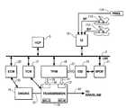
- FIG. 1schematically illustrates a model of factors impacting hydraulic flow in an exemplary hydraulic control system, in accordance with the present disclosure. Flow enters the hydraulic control system from the operation of a main hydraulic pump and/or an auxiliary hydraulic pump. Flow exits the hydraulic control system through the functions served.
- a number of control schemeshave been developed to increase fuel efficiency in an exemplary powertrain utilizing an engine.
- One exemplary schemeis to operate with an engine stopped when input torque from the engine is not needed. Such a scheme is possible in an exemplary motor vehicle when the vehicle is stopped at a traffic signal or when the vehicle is traveling down an extended decline.
- engine stopped operationis possible when another source of torque is providing for all torque requirements.
- main hydraulic pumpsare known to be powered mechanically, driven as a parasitic device from the engine.
- Hybrid powertrainsare known to operate with an engine running or stopped, depending upon the current hybrid control strategy. Under engine stopped operation in a powertrain utilizing a mechanically driven main pump, the main pump cannot provide a supply of hydraulic flow, and, instead, an auxiliary pump must be used to provide P LINE required to operate the vehicle.
- a method to accurately control P LINE in a hybrid powertrain through engine running operation, engine stopped operation, and in transition between the two engine stateswould provide useful control of the hydraulic control system.
- a method for controlling a hydraulic flow within a powertraincomprising an electromechanical transmission mechanically-operatively coupled to an engine adapted to selectively transmit power to an output, wherein the transmission utilizes a hydraulic control system serving a number of hydraulic oil consuming functions includes monitoring minimum hydraulic pressure requirements for each of the functions, determining a requested hydraulic pressure based upon the monitoring minimum hydraulic pressure requirements and physical limits of the hydraulic control system including a maximum pressure, determining a desired flow utilizing a hydraulic control system flow model based upon the requested hydraulic pressure, and utilizing the desired flow to control an auxiliary hydraulic pump.
- FIG. 1schematically illustrates a model of factors impacting hydraulic flow in an exemplary hydraulic control system, in accordance with the present disclosure
- FIG. 2is a schematic diagram of an exemplary powertrain, in accordance with the present disclosure
- FIG. 3is a schematic diagram of an exemplary architecture for a control system and powertrain, in accordance with the present disclosure
- FIG. 4is a schematic diagram of a hydraulic circuit, in accordance with the present disclosure.
- FIG. 5depicts an exemplary flow of information effective to calculate an estimated current line pressure and a maximum available line pressure, in accordance with the present disclosure
- FIG. 6depicts an exemplary flow of information utilizing modeling of the hydraulic control system to determine required hydraulic pump commands to meet requirements of functions served by the hydraulic control system, in accordance with the present disclosure
- FIG. 7graphically illustrates an exemplary hand-off event between pumps acting in the alternative, wherein hydraulic flow is maintained according to a desired flow through periods of changing engine speed, in accordance with the present disclosure
- FIG. 8graphically illustrates an exemplary method to reduce the impact of an auxiliary hydraulic pump coming up to speed during pump transitions, in accordance with the present disclosure.
- FIGS. 2 and 3depict an exemplary electro-mechanical hybrid powertrain.
- the exemplary electro-mechanical hybrid powertrain in accordance with the present disclosureis depicted in FIG. 2 , comprising a two-mode, compound-split, electro-mechanical hybrid transmission 10 operatively connected to an engine 14 and first and second electric machines (‘MG-A’) 56 and (‘MG-B’) 72 .
- the engine 14 and first and second electric machines 56 and 72each generate power which can be transmitted to the transmission 10 .
- the power generated by the engine 14 and the first and second electric machines 56 and 72 and transmitted to the transmission 10is described in terms of input torques, referred to herein as T I , T A , and T B respectively, and speed, referred to herein as N I , N A , and N B , respectively.
- the exemplary engine 14comprises a multi-cylinder internal combustion engine selectively operative in several states to transmit torque to the transmission 10 via an input shaft 12 , and can be either a spark-ignition or a compression-ignition engine.
- the engine 14includes a crankshaft (not shown) operatively coupled to the input shaft 12 of the transmission 10 .
- a rotational speed sensor 11monitors rotational speed of the input shaft 12 .
- Power output from the engine 14comprising rotational speed and output torque, can differ from the input speed, N I , and the input torque, T I , to the transmission 10 due to placement of torque-consuming components on the input shaft 12 between the engine 14 and the transmission 10 , e.g., a hydraulic pump (not shown) and/or a torque management device (not shown).
- the exemplary transmission 10comprises three planetary-gear sets 24 , 26 and 28 , and four selectively engageable torque-transmitting devices, i.e., clutches C 1 70 , C 2 62 , C 3 73 , and C 4 75 .
- clutchesrefer to any type of friction torque transfer device including single or compound plate clutches or packs, band clutches, and brakes, for example.
- a hydraulic control circuit 42preferably controlled by a transmission control module (hereafter ‘TCM’) 17 , is operative to control clutch states.
- Clutches C 2 62 and C 4 75preferably comprise hydraulically-applied rotating friction clutches.
- Clutches C 1 70 and C 3 73preferably comprise hydraulically-controlled stationary devices that can be selectively grounded to a transmission case 68 .
- Each of the clutches C 1 70 , C 2 62 , C 3 73 , and C 4 75is preferably hydraulically applied, selectively receiving pressurized hydraulic oil via the hydraulic control circuit 42 .
- the first and second electric machines 56 and 72preferably comprise three-phase AC machines, each including a stator (not shown) and a rotor (not shown), and respective resolvers 80 and 82 .
- the motor stator for each machineis grounded to an outer portion of the transmission case 68 , and includes a stator core with coiled electrical windings extending therefrom.
- the rotor for the first electric machine 56is supported on a hub plate gear that is operatively attached to shaft 60 via the second planetary gear set 26 .
- the rotor for the second electric machine 72is fixedly attached to a sleeve shaft hub 66 .
- Each of the resolvers 80 and 82preferably comprises a variable reluctance device including a resolver stator (not shown) and a resolver rotor (not shown).
- the resolvers 80 and 82are appropriately positioned and assembled on respective ones of the first and second electric machines 56 and 72 .
- Stators of respective ones of the resolvers 80 and 82are operatively connected to one of the stators for the first and second electric machines 56 and 72 .
- the resolver rotorsare operatively connected to the rotor for the corresponding first and second electric machines 56 and 72 .
- Each of the resolvers 80 and 82is signally and operatively connected to a transmission power inverter control module (hereafter ‘TPIM’) 19 , and each senses and monitors rotational position of the resolver rotor relative to the resolver stator, thus monitoring rotational position of respective ones of first and second electric machines 56 and 72 . Additionally, the signals output from the resolvers 80 and 82 are interpreted to provide the rotational speeds for first and second electric machines 56 and 72 , i.e., N A and N B , respectively.
- TPIMtransmission power inverter control module
- the transmission 10includes an output member 64 , e.g. a shaft, which is operably connected to a driveline 90 for a vehicle (not shown), to provide output power, e.g., to vehicle wheels 93 , one of which is shown in FIG. 2 .
- the output poweris characterized in terms of an output rotational speed, N O and an output torque, T O .
- a transmission output speed sensor 84monitors rotational speed and rotational direction of the output member 64 .
- Each of the vehicle wheels 93is preferably equipped with a sensor 94 adapted to monitor wheel speed, V SS-WHL , the output of which is monitored by a control module of a distributed control module system described with respect to FIG. 3 , to determine vehicle speed, and absolute and relative wheel speeds for braking control, traction control, and vehicle acceleration management.
- the input torques from the engine 14 and the first and second electric machines 56 and 72(T I , T A , and T B respectively) are generated as a result of energy conversion from fuel or electrical potential stored in an electrical energy storage device (hereafter ‘ESD’) 74 .
- the ESD 74is high voltage DC-coupled to the TPIM 19 via DC transfer conductors 27 .
- the transfer conductors 27include a contactor switch 38 . When the contactor switch 38 is closed, under normal operation, electric current can flow between the ESD 74 and the TPIM 19 . When the contactor switch 38 is opened electric current flow between the ESD 74 and the TPIM 19 is interrupted.
- the TPIM 19transmits electrical power to and from the first electric machine 56 by transfer conductors 29 , and the TPIM 19 similarly transmits electrical power to and from the second electric machine 72 by transfer conductors 31 , in response to torque commands for the first and second electric machines 56 and 72 to achieve the input torques T A and T B . Electrical current is transmitted to and from the ESD 74 in accordance with whether the ESD 74 is being charged or discharged.
- the TPIM 19includes the pair of power inverters (not shown) and respective motor control modules (not shown) configured to receive the torque commands and control inverter states therefrom for providing motor drive or regeneration functionality to meet the commanded motor torques T A and T B .
- the power inverterscomprise known complementary three-phase power electronics devices, and each includes a plurality of insulated gate bipolar transistors (not shown) for converting DC power from the ESD 74 to AC power for powering respective ones of the first and second electric machines 56 and 72 , by switching at high frequencies.
- the insulated gate bipolar transistorsform a switch mode power supply configured to receive control commands. There is typically one pair of insulated gate bipolar transistors for each phase of each of the three-phase electric machines.
- the three-phase invertersreceive or supply DC electric power via DC transfer conductors 27 and transform it to or from three-phase AC power, which is conducted to or from the first and second electric machines 56 and 72 for operation as motors or generators via transfer conductors 29 and 31 respectively.
- FIG. 3is a schematic block diagram of the distributed control module system.
- the elements described hereinaftercomprise a subset of an overall vehicle control architecture, and provide coordinated system control of the exemplary powertrain described in FIG. 2 .
- the distributed control module systemsynthesizes pertinent information and inputs, and executes algorithms to control various actuators to achieve control objectives, including objectives related to fuel economy, emissions, performance, drivability, and protection of hardware, including batteries of ESD 74 and the first and second electric machines 56 and 72 .
- the distributed control module systemincludes an engine control module (hereafter ‘ECM’) 23 , the TCM 17 , a battery pack control module (hereafter ‘BPCM’) 21 , and the TPIM 19 .
- ECMengine control module
- BPCMbattery pack control module
- a hybrid control module (hereafter ‘HCP’) 5provides supervisory control and coordination of the ECM 23 , the TCM 17 , the BPCM 21 , and the TPIM 19 .
- a user interface (‘UI’) 13is operatively connected to a plurality of devices through which a vehicle operator controls or directs operation of the electro-mechanical hybrid powertrain.
- the devicesinclude an accelerator pedal 113 (‘AP’) from which an operator torque request is determined, an operator brake pedal 112 (‘BP’), a transmission gear selector 114 (‘PRNDL’), and a vehicle speed cruise control (not shown).
- the transmission gear selector 114may have a discrete number of operator-selectable positions, including the rotational direction of the output member 64 to enable one of a forward and a reverse direction.
- the aforementioned control modulescommunicate with other control modules, sensors, and actuators via a local area network (hereafter ‘LAN’) bus 6 .
- the LAN bus 6allows for structured communication of states of operating parameters and actuator command signals between the various control modules.
- the specific communication protocol utilizedis application-specific.
- the LAN bus 6 and appropriate protocolsprovide for robust messaging and multi-control module interfacing between the aforementioned control modules, and other control modules providing functionality such as antilock braking, traction control, and vehicle stability.
- Multiple communications busesmay be used to improve communications speed and provide some level of signal redundancy and integrity. Communication between individual control modules can also be effected using a direct link, e.g., a serial peripheral interface (‘SPI’) bus (not shown).
- SPIserial peripheral interface
- the HCP 5provides supervisory control of the powertrain, serving to coordinate operation of the ECM 23 , TCM 17 , TPIM 19 , and BPCM 21 . Based upon various input signals from the user interface 13 and the powertrain, including the ESD 74 , the HCP 5 generates various commands, including: the operator torque request (‘T O — REQ ’), a commanded output torque (‘T CMD ’) to the driveline 90 , an engine input torque command, clutch torques for the torque-transfer clutches C 1 70 , C 2 62 , C 3 73 , C 4 75 of the transmission 10 ; and the torque commands for the first and second electric machines 56 and 72 , respectively.
- the operator torque request‘T O — REQ ’
- T CMDcommanded output torque
- the TCM 17is operatively connected to the hydraulic control circuit 42 and provides various functions including monitoring various pressure sensing devices (not shown) and generating and communicating control signals to various solenoids (not shown) thereby controlling pressure switches and control valves contained within the hydraulic control circuit 42 .
- the ECM 23is operatively connected to the engine 14 , and functions to acquire data from sensors and control actuators of the engine 14 over a plurality of discrete lines, shown for simplicity as an aggregate bi-directional interface cable 35 .
- the ECM 23receives the engine input torque command from the HCP 5 .
- the ECM 23determines the actual engine input torque, T I , provided to the transmission 10 at that point in time based upon monitored engine speed and load, which is communicated to the HCP 5 .
- the ECM 23monitors input from the rotational speed sensor 11 to determine the engine input speed to the input shaft 12 , which translates to the transmission input speed, N I .
- the ECM 23monitors inputs from sensors (not shown) to determine states of other engine operating parameters including, e.g., a manifold pressure, engine coolant temperature, ambient air temperature, and ambient pressure.
- the engine loadcan be determined, for example, from the manifold pressure, or alternatively, from monitoring operator input to the accelerator pedal 113 .
- the ECM 23generates and communicates command signals to control engine actuators, including, e.g., fuel injectors, ignition modules, and throttle control modules, none of which are shown.
- the TCM 17is operatively connected to the transmission 10 and monitors inputs from sensors (not shown) to determine states of transmission operating parameters.
- the TCM 17generates and communicates command signals to control the transmission 10 , including controlling the hydraulic control circuit 42 .
- Inputs from the TCM 17 to the HCP 5include estimated clutch torques for each of the clutches, i.e., C 1 70 , C 2 62 , C 3 73 , and C 4 75 , and rotational output speed, N O , of the output member 64 .
- Other actuators and sensorsmay be used to provide additional information from the TCM 17 to the HCP 5 for control purposes.
- the TCM 17monitors inputs from pressure switches (not shown) and selectively actuates pressure control solenoids (not shown) and shift solenoids (not shown) of the hydraulic control circuit 42 to selectively actuate the various clutches C 1 70 , C 2 62 , C 3 73 , and C 4 75 to achieve various transmission operating range states, as described hereinbelow.
- the BPCM 21is signally connected to sensors (not shown) to monitor the ESD 74 , including states of electrical current and voltage parameters, to provide information indicative of parametric states of the batteries of the ESD 74 to the HCP 5 .
- the parametric states of the batteriespreferably include battery state-of-charge, battery voltage, battery temperature, and available battery power, referred to as a range P BAT — MIN to P BAT — MAX .
- Each of the control modules ECM 23 , TCM 17 , TPIM 19 and BPCM 21is preferably a general-purpose digital computer comprising a microprocessor or central processing unit, storage mediums comprising read only memory (‘ROM’), random access memory (‘RAM’), electrically programmable read only memory (‘EPROM’), a high speed clock, analog to digital (‘A/D’) and digital to analog (‘D/A’) circuitry, and input/output circuitry and devices (‘I/O’) and appropriate signal conditioning and buffer circuitry.
- Each of the control moduleshas a set of control algorithms, comprising resident program instructions and calibrations stored in one of the storage mediums and executed to provide the respective functions of each computer.
- control algorithmsare executed during preset loop cycles such that each algorithm is executed at least once each loop cycle.
- Algorithms stored in the non-volatile memory devicesare executed by one of the central processing units to monitor inputs from the sensing devices and execute control and diagnostic routines to control operation of the actuators, using preset calibrations.
- Loop cyclesare executed at regular intervals, for example each 3.125, 6.25, 12.5, 25 and 100 milliseconds during ongoing operation of the powertrain. Alternatively, algorithms may be executed in response to the occurrence of an event.
- the exemplary powertrainselectively operates in one of several operating range states that can be described in terms of an engine state comprising one of an engine on state (‘ON’) and an engine off state (‘OFF’), and a transmission state comprising a plurality of fixed gears and continuously variable operating modes, described with reference to Table 1, below.
- Each of the transmission operating range statesis described in the table and indicates which of the specific clutches C 1 70 , C 2 62 , C 3 73 , and C 4 75 are applied for each of the operating range states.
- a first continuously variable modei.e., EVT Mode I, or MI
- the engine statecan be one of ON (‘MI_Eng_On’) or OFF (‘MI_Eng_Off’).
- a second continuously variable modei.e., EVT Mode II, or MII, is selected by applying clutch C 2 62 only to connect the shaft 60 to the carrier of the third planetary gear set 28 .
- the engine statecan be one of ON (‘MII_Eng_On’) or OFF (‘MII_Eng_Off’).
- RPMrevolutions per minute
- a fixed gear operationprovides a fixed ratio operation of input-to-output speed of the transmission 10 , i.e., N I /N O , is achieved.
- a first fixed gear operation(‘FG1’) is selected by applying clutches C 1 70 and C 4 75 .
- a second fixed gear operation(‘FG2’) is selected by applying clutches C 1 70 and C 2 62 .
- a third fixed gear operation(‘FG3’) is selected by applying clutches C 2 62 and C 4 75 .
- a fourth fixed gear operation (‘FG4’)is selected by applying clutches C 2 62 and C 3 73 .
- the fixed ratio operation of input-to-output speedincreases with increased fixed gear operation due to decreased gear ratios in the planetary gears 24 , 26 , and 28 .
- the rotational speeds of the first and second electric machines 56 and 72 , N A and N B respectively,are dependent on internal rotation of the mechanism as defined by the clutching and are proportional to the input speed measured at the input shaft 12 .
- the HCP 5 and one or more of the other control modulesdetermine the commanded output torque, T CMD , intended to meet the operator torque request, T O — REQ , to be executed at the output member 64 and transmitted to the driveline 90 .
- Final vehicle accelerationis affected by other factors including, e.g., road load, road grade, and vehicle mass.
- the operating range stateis determined for the transmission 10 based upon a variety of operating characteristics of the powertrain. This includes the operator torque request, communicated through the accelerator pedal 113 and brake pedal 112 to the user interface 13 as previously described.
- the operating range statemay be predicated on a powertrain torque demand caused by a command to operate the first and second electric machines 56 and 72 in an electrical energy generating mode or in a torque generating mode.
- the operating range statecan be determined by an optimization algorithm or routine which determines optimum system efficiency based upon operator demand for power, battery state of charge, and energy efficiencies of the engine 14 and the first and second electric machines 56 and 72 .
- the control systemmanages torque inputs from the engine 14 and the first and second electric machines 56 and 72 based upon an outcome of the executed optimization routine, and system efficiencies are optimized thereby, to manage fuel economy and battery charging. Furthermore, operation can be determined based upon a fault in a component or system.
- the HCP 5monitors the torque-generative devices, and determines the power output from the transmission 10 required to achieve the desired output torque to meet the operator torque request.
- the ESD 74 and the first and second electric machines 56 and 72are electrically-operatively coupled for power flow therebetween.
- the engine 14 , the first and second electric machines 56 and 72 , and the electro-mechanical transmission 10are mechanically-operatively coupled to transmit power therebetween to generate a power flow to the output member 64 .
- FIG. 4depicts a schematic diagram of the hydraulic control circuit 42 for controlling flow of hydraulic oil in the exemplary transmission.
- a main hydraulic pump 88is driven off the input shaft 12 from the engine 14 , and an auxiliary pump 110 controlled by the TPIM 19 to provide pressurized fluid to the hydraulic control circuit 42 through valve 140 .
- the auxiliary pump 110preferably comprises an electrically-powered pump of an appropriate size and capacity to provide sufficient flow of pressurized hydraulic oil into the hydraulic control circuit 42 when operational.
- the hydraulic control circuit 42selectively distributes hydraulic pressure to a plurality of devices, including the torque-transfer clutches C 1 70 , C 2 62 , C 3 73 , and C 4 75 , active cooling circuits for the first and second electric machines 56 and 72 (not shown), and a base cooling circuit for cooling and lubricating the transmission 10 via passages 142 , 144 (not depicted in detail).
- the TCM 17actuates the various clutches to achieve one of the transmission operating range states through selective actuation of hydraulic circuit flow control devices comprising variable pressure control solenoids (‘PCS’) PCS 1 108 , PCS 2 114 , PCS 3 112 , PCS 4 116 and solenoid-controlled flow management valves, X-valve 119 and Y-valve 121 .
- the hydraulic control circuit 42is fluidly connected to pressure switches PS 1 , PS 2 , PS 3 , and PS 4 via passages 122 , 124 , 126 , and 128 , respectively.
- the pressure control solenoid PCS 1 108has a control position of normally high and is operative to modulate the magnitude of fluidic pressure in the hydraulic circuit through fluidic interaction with controllable pressure regulator 107 and spool valve 109 .
- the controllable pressure regulator 107 and spool valve 109interact with PCS 1 108 to control hydraulic pressure in the hydraulic control circuit 42 over a range of pressures and may provide additional functionality for the hydraulic control circuit 42 .
- Pressure control solenoid PCS 3 112has a control position of normally high, and is fluidly connected to spool valve 113 and operative to effect flow therethrough when actuated. Spool valve 113 is fluidly connected to pressure switch PS 3 via passage 126 .
- Pressure control solenoid PCS 2 114has a control position of normally high, and is fluidly connected to spool valve 115 and operative to effect flow therethrough when actuated. Spool valve 115 is fluidly connected to pressure switch PS 2 via passage 124 .
- Pressure control solenoid PCS 4 116has a control position of normally low, and is fluidly connected to spool valve 117 and operative to effect flow therethrough when actuated. Spool valve 117 is fluidly connected to pressure switch PS 4 via passage 128 .
- the X-Valve 119 and Y-Valve 121each comprise flow management valves controlled by solenoids 118 , 120 , respectively, in the exemplary system, and have control states of High (‘1’) and Low (‘0’).
- the control statesrefer to positions of each valve to which control flow to different devices in the hydraulic control circuit 42 and the transmission 10 .
- the X-valve 119is operative to direct pressurized fluid to clutches C 3 73 and C 4 75 and cooling systems for stators of the first and second electric machines 56 and 72 via fluidic passages 136 , 138 , 144 , 142 respectively, depending upon the source of the fluidic input, as is described hereinafter.
- the Y-valve 121is operative to direct pressurized fluid to clutches C 1 70 and C 2 62 via fluidic passages 132 and 134 respectively, depending upon the source of the fluidic input, as is described hereinafter.
- the Y-valve 121is fluidly connected to pressure switch PS 1 via passage 122 .
- the hydraulic control circuit 42includes a base cooling circuit for providing hydraulic oil to cool the stators of the first and second electric machines 56 and 72 .
- the base cooling circuitincludes fluid conduits from the valve 140 flowing directly to a flow restrictor which leads to fluidic passage 144 leading to the base cooling circuit for the stator of the first electric machine 56 , and to a flow restrictor which leads to fluidic passage 142 leading to the base cooling circuit for the stator of the second electric machine 72 .
- Active cooling of stators for the first and second electric machines 56 and 72is effected by selective actuation of pressure control solenoids PCS 2 114 , PCS 3 112 and PCS 4 116 and solenoid-controlled flow management valves X-valve 119 and Y-valve 121 , which leads to flow of hydraulic oil around the selected stator and permits heat to be transferred therebetween, primarily through conduction.
- An exemplary logic table to accomplish control of the exemplary hydraulic control circuit 42 to control operation of the transmission 10 in one of the transmission operating range statesis provided with reference to Table 2, below.
- a Low Rangeis defined as a transmission operating range state comprising one of the first continuously variable mode and the first and second fixed gear operations.
- a High Rangeis defined as a transmission operating range state comprising one of the second continuously variable mode and the third and fourth fixed gear operations.
- a transmission operating range statei.e. one of the fixed gear and continuously variable mode operations, is selected for the exemplary transmission 10 based upon a variety of operating characteristics of the powertrain. This includes the operator torque request, typically communicated through inputs to the UI 13 as previously described. Additionally, a demand for output torque is predicated on external conditions, including, e.g., road grade, road surface conditions, or wind load.
- the operating range statemay be predicated on a powertrain torque demand caused by a control module command to operate of the electrical machines in an electrical energy generating mode or in a torque generating mode.
- the operating range statecan be determined by an optimization algorithm or routine operable to determine an optimum system efficiency based upon the operator torque request, battery state of charge, and energy efficiencies of the engine 14 and the first and second electric machines 56 and 72 .
- the control systemmanages the input torques from the engine 14 and the first and second electric machines 56 and 72 based upon an outcome of the executed optimization routine, and system optimization occurs to improve fuel economy and manage battery charging. Furthermore, the operation can be determined based upon a fault in a component or system.
- the purpose of the hydraulic control systemis to provide pressurized hydraulic oil for a number of functions throughout a hybrid powertrain.
- control of the hydraulic control system in order to enable smooth and consistent operation of the functions served by providing a supply of hydraulic flowrequires an understanding of P LINE .
- P LINEis important to understanding the capacity of the hydraulic control system to fill flow requirements to required functions through static and dynamic conditions.
- P LINEis also important to managing the operation of the pump or pumps utilized to provide the supply of hydraulic flow to the hydraulic control system.
- P LINEdescribes the capacity that the hydraulic control system possesses to fulfill a required function. For instance, in a clutch control function, P LINE describes the maximum clamping force immediately available to the clutch. As described above, the capacity of the clutch to transmit reactive torque depends upon the clamping force applied to the clutch. Additionally, it will be appreciated that P LINE describes how quickly the clutch can be filled. In another example, one having ordinary skill in the art will appreciate that, with regards to electric machine cooling, either serving a base machine cooling function through the electric machine or selectively serving an active machine cooling function, the quantity of hydraulic oil passing through the heat exchange mechanism of the electric machine and the resulting heat exchange capacity of the function rise as a function of P LINE .
- hydraulic oilcan be used to lubricate a device, for instance, a bearing.
- the resulting flow to the device through a fixed orifice and the resulting ability of the hydraulic flow to meet the lubrication functionis a function of P LINE .
- P MIN for each function servedcan be used collectively to describe a minimum required P LINE that is required for the hydraulic control system at any point. For example, if an exemplary hydraulic control system serves four hydraulic clutches, a base electric machine cooling circuit, and an active electric machine cooling circuit, the required P LINE at any instant can be described by the maximum of the P MIN values. Alternatively, P MIN values can be predicted for some time period in advance, and P LINE can be set to the maximum P MIN value through that time period. In this way, P MIN values can be used to provide operating requirements to the hydraulic control system.
- P LINEis important to managing the supply of hydraulic flow resulting from operation of the pump or pumps utilized to provide the supply of hydraulic flow to the hydraulic control system, describing both an input to the operation of the pumps by describing the back pressure exerted on the pumps and also providing feedback to the operation of the pump or pumps providing a comparison to drive P LINE to a desired line pressure value.
- P MAXcan be defined, describing the maximum P LINE that can be generated if the current operational pumps were controlled to their highest flow settings.
- P MAXcan include activating pumps, such an auxiliary pump, not currently active and can also include modulating or restricting functions consuming supply of hydraulic flow from the hydraulic control system.
- P MAXis useful to supply hydraulic flow to priority functions requiring high P LINE values, for instance, as required to quickly fill a transmission clutch.
- main hydraulic pumpsare known to be powered mechanically from the engine.
- Hybrid powertrainstaking full advantage of fuel efficient operating strategies, are known to operate with an engine running or stopped. Under engine stopped operation in a powertrain utilizing a mechanically driven main pump, the main pump cannot provide a supply of hydraulic flow, and, instead, an auxiliary pump must be used to provide P LINE required for operation of the various functions served by the hydraulic control system.
- a method to accurately control P LINE in a hybrid powertrain in conjunction with engine running operation, engine stopped operation, and transitions therebetweenis provided.
- P DESIREDcan include immediate requirements of the hydraulic control system based upon P LINEEST , for instance, based upon a projections of P MIN for each function served by the hydraulic control system. Additionally, P DESIRED can include projections of expected requirements, for instance, a projected shift based upon accelerator pedal position or data available from such sources as historical driving patterns or a digital map device or increasing electric machine temperatures expected to soon require active cooling.
- P DESIREDValues, derivations, and modifying factors for determining P DESIRED may be developed experimentally, empirically, predictively, through modeling or other techniques adequate to accurately predict hydraulic control system operation, and a multitude of criteria for setting P DESIRED might be used by the same engine for each cylinder and for different engine settings, conditions, or operating ranges.
- P DESIREDcan be set to P MAX or simply be commanded to a maximum value.
- Many factorsare contemplated that can impact a selection of P DESIRED , and the disclosure is not intended to be limited to the particular embodiments described herein. If no factors or motivations suggest that P DESIRED be set at an elevated level, P DESIRED can be set to a maximum P MIN according to current conditions in order to reduce power demands of the hydraulic pumps to the lowest possible level.
- P DESIREDcan be utilized to describe operating requirements of the hydraulic control system; however, physical limits and operational concerns can impact selection of a P LINE to be commanded.
- P MAXcan be described by P AVAIL or the maximum P LINE that can be achieved by the hydraulic control system under current operation conditions. Regardless of P DESIRED , P LINE cannot exceed P MAX .
- P MINSYSTEMcan be described as a minimum pressure required of the hydraulic control system under any circumstances, for example, to meet unexpected demands of the hydraulic control system with an acceptable response time.
- P DESIREDafter comparison and adjustment to limits upon the hydraulic control system, can be modified to a P REQUEST for use in controlling pump operation.
- FIG. 5depicts an exemplary flow of information effective to calculate P LINEEST and P AVAIL , in accordance with the present disclosure.
- Process 300includes a determination of flows into and out of the hydraulic control system in order to estimate both P LINEEST , an estimate of current line pressure, and P AVAIL , an estimate of line pressure that could be achieved under current operating conditions.
- Process 300comprises summation block 350 describing FLOW_AVAIL or the current balance of flows within the hydraulic control system; integration module 355 integrating the FLOW_AVAIL signal in order to sum the overall effects of flow on P LINE through a period of time and provide P LINEEST ; summation block 360 describing FLOW_AVAIL_MAX or the possible balance of flows within the hydraulic control system if the system were operated at a maximum pressure; and integration module 365 integrating the FLOW_AVAIL_MAX signal in order to sum the overall effects of flow on P LINE through a period of time and provide P AVAIL .
- P LINEEST and P AVAILcan be determined for use in controlling the hydraulic control system.
- FLOW_EFFECTIVEis an estimation of current hydraulic flow into the system. Flows in an exemplary system can originate from either a main hydraulic pump or an auxiliary hydraulic pump. In some systems, flow can originate from both pumps, and FLOW_EFFECTIVE could include a summation of a FLOW_MAIN from the main hydraulic pump and a FLOW_AUX from the auxiliary hydraulic pump. In the embodiment described in FIG. 5 , flows from the two pumps are not summed, but rather the pump with the greater flow supplies the FLOW_EFFECTIVE. Physical embodiments of this configuration can include a check valve determining the greater flow and some means to cut off the source of the lesser flow. In FIG.
- max block 330is used to determine the greater of FLOW_MAIN and FLOW_AUX terms for use as FLOW_EFFECTIVE.
- FLOW_MAINis determined in main pump flow block 310 from inputs including N MAIN ; T OIL describing the behavior of hydraulic oil as a result of temperature; and P LINEEST describing the effects of P LINE creating back pressure working against the pump. N MAIN can be described as depicted in FIG. 5 through N I .
- FLOW_AUXis determined in aux pump flow block 315 from inputs including N AUX , the speed of the auxiliary hydraulic pump; T OIL ; and P LINEEST .
- FLOW_CONSUMEDis an estimation of current hydraulic flow out of the hydraulic control system.
- FLOW_CONSUMEDis determined at summation block 340 , summing the flows from the functions served by the hydraulic control system.
- FIG. 5includes exemplary functions described comprising a lube flow; a leakage flow; an active electric machine cooling flow; a base electric machine cooling flow; and flows serving transmission clutches.
- FLOW_EFFECTIVE and FLOW_CONSUMEDare summed at block 350 , and the net flow in the hydraulic control system is output as FLOW_AVAIL.
- FLOW_MAXis an estimation of maximum hydraulic flow that could be delivered into the system under current operating conditions. As described above, flows in an exemplary system can originate from either a main hydraulic pump or an auxiliary hydraulic pump. In some systems, flow can originate from both pumps, and FLOW_MAX could include a summation of a FLOW_MAIN from the main hydraulic pump and a FLOW_AUX_MAX from the auxiliary hydraulic pump. It will be appreciated that while output of an electrically powered auxiliary hydraulic pump can be modulated to provide a maximum output, output from a directly driven main hydraulic pump is dependent upon N I , and, therefore, does not have a maximum output equivalent.
- FLOW_AUX_MAXis determined in aux pump max flow block 320 from inputs including N AUXMAX , the maximum achievable speed of auxiliary hydraulic pump; and P AUXMAX , the maximum achievable pressure from the auxiliary hydraulic pump.
- FLOW_CONSUMED P AVAILis determined at summation block 345 , summing the flows from the functions served by the hydraulic control system, estimated if P LINE equaled P AVAIL . As described above, different functions can be served by the hydraulic control system.
- FLOW_MAX and FLOW_CONSUMED@P AVAILare summed at block 360 , and the net flow in the hydraulic control system is output as FLOW_AVAIL_MAX.
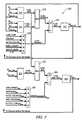
- FIG. 6depicts an exemplary flow of information utilizing modeling of the hydraulic control system to determine required hydraulic pump commands to meet requirements of functions served by the hydraulic control system, in accordance with the present disclosure.
- Process 400comprises max block 430 determining P DESIRED based upon P MIN terms describing minimum hydraulic flow requirements from functions served by the hydraulic control system; main pump controller 410 ; and aux pump controller 420 .
- P LINE within the hydraulic control systemis dependent upon a number of factors including pump operation and the various flows consumed by functions served by the hydraulic control system.
- Inputs to max block 430include P MIN terms based upon calibrations, sensor readings, or algorithms based upon the individual functions served.
- P MIN termscan include various adjustments and scaling factors depending upon transient operation of the powertrain and any other information available required to predict upcoming demands upon the hydraulic control system. If these P MIN terms, block 430 selects the greatest of these terms and sets P DESIRED according to the selected P MIN term.
- P DESIREDis fed to block 440 , wherein physical limits upon P LINE are imposed upon P DESIRED , and P REQUEST is generated to command required line pressure.
- P REQUESTis fed to main pump controller 410 , and changes are made to operation of the hydraulic control system and operation of the pump, such as changes to flow restrictor commands, based upon P REQUEST .
- P REQUESTis also fed to aux flow determination module 450 .
- Aux flow determination module 450inputs P REQUEST and T OIL , applies programming based upon flow modeling of the hydraulic control system as described above, and determines a DESIRED FLOW from the auxiliary hydraulic pump necessary to meet P REQUEST .
- Programming of module 450utilizes flows estimated to result from P REQUEST . An exemplary depiction of such processing can be shown referring back to FIG. 5 , block 345 .
- Module 450can similarly input LUBE_FLOW@P REQUEST , LEAKAGE@P REQUEST , and other required terms associated with functions served, utilize appropriate factors such as T OIL , and determines the DESIRED FLOW from the auxiliary pump required to meet P REQUEST .
- Aux pump controller 420inputs the DESIRED FLOW, along with inputs including FLOW_AUX_MAX, FLOW_MAIN, and a measure of auxiliary pump availability, describing, for example, electrical power available to power the auxiliary hydraulic pump. Additionally, aux pump controller 420 can include an input from HCP 460 of an aux pump primer.
- engine control strategiescan include engine stopped operation, wherein an engine can be stopped when not needed.
- an aux pump primercan be sent to aux pump controller 420 including an instruction to power up the auxiliary hydraulic pump to meet a pending shut down of the main hydraulic pump. In this way, extended periods of P LINE below requested levels associated with the auxiliary pump coming up to speed can be avoided.
- FIG. 6describes an exemplary flow of information accomplishing pump control based upon needs to functions served by the hydraulic control system, it will be appreciated that a number of embodiments are possible accomplishing such control based upon methods described herein, and the disclosure is not intended to be limited to the particular embodiments described herein.
- FIG. 7graphically illustrates an exemplary hand-off event between pumps acting in the alternative, wherein hydraulic flow is maintained according to a desired flow through periods of changing engine speed, in accordance with the present disclosure.
- N I and hydraulic floware depicted through a time span.
- N Iis directly linked to speed of an exemplary main hydraulic pump directly driven by the engine, and, therefore, resulting hydraulic flow from operation of the main pump, or FLOW_MAIN, is substantially proportional to N I .
- FLOW_MAINAs N I drops, so does FLOW_MAIN, and FLOW_MAIN eventually falls below desired flow.
- a methodis disclosed wherein a transition threshold is utilized, such that when FLOW_MAIN is detected below the desired flow by more than the threshold amount, a transition from the main hydraulic pump to the auxiliary hydraulic pump is commanded.
- flow from the auxiliary pumpor FLOW_AUX
- the auxiliary pumpcontinues to supply hydraulic flow until operation of the main pump supplies hydraulic flow in excess of FLOW_AUX.
- the transition from auxiliary pump operation to main pump operationcan be handled in a number of ways.
- a check valve acting according to the difference in the flowscan be utilized to select hydraulic flow to the hydraulic control system and can include a cut-off or leak path mechanism for the de-selected pump.
- Another method to transition from auxiliary pump operation to main pump operationis to continue to operate the auxiliary hydraulic pump despite main pump operation until FLOW_MAIN exceeds the desired flow by more than a transition threshold.
- transition thresholdssuch as the thresholds depicted in FIG. 7 avoid unnecessary transition events. For example, in a case where engine speed varies between the two transition levels and crosses the desired flow a number of times, transitions commanded without the transition thresholds, commanded by a simple comparison to desired flow, will create multiple auxiliary pump on and off commands.
- FIG. 8graphically illustrates an exemplary method to reduce the impact of an auxiliary hydraulic pump coming up to speed during pump transitions, in accordance with the present disclosure.
- Pump speed and hydraulic floware depicted through a time span.
- Conditions illustrated at the left extreme of the graphdepict an operating situation in which hydraulic flow is being supplied as a FLOW_MAIN from a directly driven main hydraulic pump.
- a commandis initiated in the strategic control of the powertrain to stop the engine.
- Such a commandcan be initiated as part of a hybrid control strategy, wherein an electric machine or electric machines are going to be utilized to provide torque to the output, or such a command can be used in an idle or a coasting condition when engine input is not needed.
- An aux pump primer commandis initiated to preemptively bring the auxiliary pump up to speed in order to avoid the aforementioned lag time associated with an idled auxiliary pump.
- the exemplary aux pump primer commandis issued a calibrated lead time before the expected initiation of the engine stop condition to the engine.
- the calibrated lead timecan be set experimentally, empirically, predictively, through modeling or other techniques adequate to accurately predict engine and pump operation, and a multitude of calibration lead times might be used by the same hydraulic control system for different engine settings, conditions, or operating ranges. Because the aux pump primer command is issued before the main pump speed and associated FLOW_MAIN fall below the desired flow, the auxiliary pump has time to come up to speed and reduce any substantial transitory effects to hydraulic flow during the handoff.
- FIG. 8demonstrates a method to reduce transitory effects to hydraulic flow of an engine stop command. It will be appreciated that a similar technique can be used in anticipation of a predicted slowing of N I to levels that would not support a desired flow. For example, in a vehicular application, predictions regarding N I can be based upon real-time data or can be based upon road slope, road sensing devices, geographical or 3D map data. For example, if N I shows a steep decline which will cause FLOW_MAIN to fall below the desired flow in 1.5 seconds, an aux pump primer command can be immediately issued to bring the auxiliary pump up to speed.
- Road slope datafor example, an indication that the vehicle is on a steep downward incline, indicating that the engine speed is likely to be greatly reduced or stopped, can be utilized to predictively send an aux pump primer command.
- engine operationcan be predicted based upon radar systems, vision systems, vehicle-to-vehicle communication, or other means to determine predicted engine speeds, forecasted, for example, by stopped traffic, a traffic signal, or slowing traffic, appropriate aux pump primer commands can issued.
- location of the vehiclecan be determined by a GPS device in association with a 3D map, geographic details, traffic patterns, weather reports, and other such information that could indicate a pending change in engine usage.
- information regarding a predicted change to N Ican be used to predictively issue aux pump primer commands to reduce transient effects of pump handoffs to hydraulic flow in a hydraulic control system.
Landscapes
- Engineering & Computer Science (AREA)
- General Engineering & Computer Science (AREA)
- Mechanical Engineering (AREA)
- Control Of Transmission Device (AREA)
- Control Of Vehicle Engines Or Engines For Specific Uses (AREA)
- Hybrid Electric Vehicles (AREA)
- Electric Propulsion And Braking For Vehicles (AREA)
Abstract
Description
| TABLE 1 | |||
| Engine | Transmission Operating | Applied | |
| Description | State | Range State | Clutches |
| MI_Eng_Off | OFF | EVT | C1 | 70 | |
| MI_Eng_On | ON | EVT | C1 | 70 | |
| FG1 | ON | Fixed Gear Ratio 1 | |||
| FG2 | ON | Fixed Gear Ratio 2 | |||
| MII_Eng_Off | OFF | EVT | C2 | 62 | |
| MII_Eng_On | ON | EVT | C2 | 62 | |
| FG3 | ON | Fixed Gear Ratio 3 | |||
| FG4 | ON | Fixed Gear Ratio 4 | |||
| TABLE 2 | ||||||
| X- | Y- | |||||
| Transmission | Valve | Valve | ||||
| Operating | Logic | Logic | PCS1 | PCS2 | PCS3 | PCS4 |
| Range | No | C2 | Normal | Normal | Normal | Normal |
| State | Latch | Latch | High | High | High | Low |
| EVT | 0 | 0 | Line | MG-B | C1 | MG-A |
| Mode I | Modulation | Stator | Stator | |||
| Cool | Cool | |||||
| EVT | 0 | 1 | Line | C2 | MG-B | MG-A |
| Mode II | Modulation | Stator | Stator | |||
| Cool | Cool | |||||
| Low | 1 | 0 | Line | C2 | C1 | C4 |
| Range | Modulation | |||||
| High | 1 | 1 | Line | C2 | C3 | C4 |
| Range | Modulation | |||||
Claims (17)
Priority Applications (3)
| Application Number | Priority Date | Filing Date | Title |
|---|---|---|---|
| US12/250,296US8170762B2 (en) | 2007-10-29 | 2008-10-13 | Method and apparatus to control operation of a hydraulic pump for an electro-mechanical transmission |
| EP08018829.5AEP2055997B1 (en) | 2007-10-29 | 2008-10-28 | Method and apparatus to control operation of a hydraulic pump for an electro-mechanical transmission |
| CN200810173871.8ACN101531196B (en) | 2007-10-29 | 2008-10-29 | Method and apparatus to control operation of a hydraulic pump for an electro-mechanical transmission |
Applications Claiming Priority (2)
| Application Number | Priority Date | Filing Date | Title |
|---|---|---|---|
| US98327307P | 2007-10-29 | 2007-10-29 | |
| US12/250,296US8170762B2 (en) | 2007-10-29 | 2008-10-13 | Method and apparatus to control operation of a hydraulic pump for an electro-mechanical transmission |
Publications (2)
| Publication Number | Publication Date |
|---|---|
| US20090112423A1 US20090112423A1 (en) | 2009-04-30 |
| US8170762B2true US8170762B2 (en) | 2012-05-01 |
Family
ID=40276247
Family Applications (1)
| Application Number | Title | Priority Date | Filing Date |
|---|---|---|---|
| US12/250,296Active2031-02-15US8170762B2 (en) | 2007-10-29 | 2008-10-13 | Method and apparatus to control operation of a hydraulic pump for an electro-mechanical transmission |
Country Status (3)
| Country | Link |
|---|---|
| US (1) | US8170762B2 (en) |
| EP (1) | EP2055997B1 (en) |
| CN (1) | CN101531196B (en) |
Cited By (12)
| Publication number | Priority date | Publication date | Assignee | Title |
|---|---|---|---|---|
| US20100228452A1 (en)* | 2009-03-09 | 2010-09-09 | Aisin Seiki Kabushiki Kaisha | Hydraulic pressure controlling apparatus |
| US20100228451A1 (en)* | 2009-03-09 | 2010-09-09 | Aisin Seiki Kabushiki Kaisha | Hydraulic pressure controlling apparatus |
| US20120109478A1 (en)* | 2010-11-01 | 2012-05-03 | Jatco Ltd | Hydraulic control apparatus for vehicle |
| US8579759B2 (en) | 2010-11-01 | 2013-11-12 | Jatco Ltd | Vehicle control apparatus and vehicle control method |
| US8636620B2 (en) | 2010-10-28 | 2014-01-28 | Jatco Ltd | Automatic transmission |
| US8672805B2 (en) | 2011-02-03 | 2014-03-18 | Jatco Ltd | Vehicle control apparatus and vehicle control method |
| US8725333B2 (en) | 2010-11-01 | 2014-05-13 | Jatco Ltd | Control apparatus for vehicle and control method therefor |
| US8763736B2 (en) | 2010-11-02 | 2014-07-01 | Jatco Ltd | Control apparatus and method for hybrid vehicle |
| US9651144B2 (en) | 2012-10-31 | 2017-05-16 | Allison Transmission, Inc. | Method of controlling a hydraulic pressurization system of a transmission |
| US11378102B1 (en) | 2021-07-28 | 2022-07-05 | Deere & Company | Flow management of a hydraulic system |
| US11378104B1 (en) | 2021-07-28 | 2022-07-05 | Deere & Company | Flow management of a hydraulic system |
| US11377823B1 (en) | 2021-07-28 | 2022-07-05 | Deere & Company | Flow management of a hydraulic system |
Families Citing this family (142)
| Publication number | Priority date | Publication date | Assignee | Title |
|---|---|---|---|---|
| US8390240B2 (en)* | 2007-08-06 | 2013-03-05 | GM Global Technology Operations LLC | Absolute position sensor for field-oriented control of an induction motor |
| US7867135B2 (en) | 2007-09-26 | 2011-01-11 | GM Global Technology Operations LLC | Electro-mechanical transmission control system |
| US8234048B2 (en)* | 2007-10-19 | 2012-07-31 | GM Global Technology Operations LLC | Method and system for inhibiting operation in a commanded operating range state for a transmission of a powertrain system |
| US9140337B2 (en)* | 2007-10-23 | 2015-09-22 | GM Global Technology Operations LLC | Method for model based clutch control and torque estimation |
| US8060267B2 (en)* | 2007-10-23 | 2011-11-15 | GM Global Technology Operations LLC | Method for controlling power flow within a powertrain system |
| US8335623B2 (en)* | 2007-10-25 | 2012-12-18 | GM Global Technology Operations LLC | Method and apparatus for remediation of and recovery from a clutch slip event in a hybrid powertrain system |
| US8296027B2 (en) | 2007-10-25 | 2012-10-23 | GM Global Technology Operations LLC | Method and apparatus to control off-going clutch torque during torque phase for a hybrid powertrain system |
| US8187145B2 (en)* | 2007-10-25 | 2012-05-29 | GM Global Technology Operations LLC | Method and apparatus for clutch torque control in mode and fixed gear for a hybrid powertrain system |
| US8265821B2 (en)* | 2007-10-25 | 2012-09-11 | GM Global Technology Operations LLC | Method for determining a voltage level across an electric circuit of a powertrain |
| US8118122B2 (en)* | 2007-10-25 | 2012-02-21 | GM Global Technology Operations LLC | Method and system for monitoring signal integrity in a distributed controls system |
| US8406945B2 (en)* | 2007-10-26 | 2013-03-26 | GM Global Technology Operations LLC | Method and apparatus to control logic valves for hydraulic flow control in an electro-mechanical transmission |
| US9097337B2 (en)* | 2007-10-26 | 2015-08-04 | GM Global Technology Operations LLC | Method and apparatus to control hydraulic line pressure in an electro-mechanical transmission |
| US7985154B2 (en)* | 2007-10-26 | 2011-07-26 | GM Global Technology Operations LLC | Method and apparatus to control hydraulic pressure for component lubrication in an electro-mechanical transmission |
| US8303463B2 (en)* | 2007-10-26 | 2012-11-06 | GM Global Technology Operations LLC | Method and apparatus to control clutch fill pressure in an electro-mechanical transmission |
| US8204702B2 (en)* | 2007-10-26 | 2012-06-19 | GM Global Technology Operations LLC | Method for estimating battery life in a hybrid powertrain |
| US8548703B2 (en) | 2007-10-26 | 2013-10-01 | GM Global Technology Operations LLC | Method and apparatus to determine clutch slippage in an electro-mechanical transmission |
| US8167773B2 (en) | 2007-10-26 | 2012-05-01 | GM Global Technology Operations LLC | Method and apparatus to control motor cooling in an electro-mechanical transmission |
| US8560191B2 (en) | 2007-10-26 | 2013-10-15 | GM Global Technology Operations LLC | Method and apparatus to control clutch pressures in an electro-mechanical transmission |
| US8428816B2 (en)* | 2007-10-27 | 2013-04-23 | GM Global Technology Operations LLC | Method and apparatus for monitoring software and signal integrity in a distributed control module system for a powertrain system |
| US8062174B2 (en)* | 2007-10-27 | 2011-11-22 | GM Global Technology Operations LLC | Method and apparatus to control clutch stroke volume in an electro-mechanical transmission |
| US8244426B2 (en)* | 2007-10-27 | 2012-08-14 | GM Global Technology Operations LLC | Method and apparatus for monitoring processor integrity in a distributed control module system for a powertrain system |
| US8099219B2 (en) | 2007-10-27 | 2012-01-17 | GM Global Technology Operations LLC | Method and apparatus for securing an operating range state mechanical transmission |
| US8290681B2 (en)* | 2007-10-29 | 2012-10-16 | GM Global Technology Operations LLC | Method and apparatus to produce a smooth input speed profile in mode for a hybrid powertrain system |
| US8112194B2 (en)* | 2007-10-29 | 2012-02-07 | GM Global Technology Operations LLC | Method and apparatus for monitoring regenerative operation in a hybrid powertrain system |
| US8489293B2 (en)* | 2007-10-29 | 2013-07-16 | GM Global Technology Operations LLC | Method and apparatus to control input speed profile during inertia speed phase for a hybrid powertrain system |
| US8095254B2 (en)* | 2007-10-29 | 2012-01-10 | GM Global Technology Operations LLC | Method for determining a power constraint for controlling a powertrain system |
| US8209098B2 (en)* | 2007-10-29 | 2012-06-26 | GM Global Technology Operations LLC | Method and apparatus for monitoring a transmission range selector in a hybrid powertrain transmission |
| US8282526B2 (en)* | 2007-10-29 | 2012-10-09 | GM Global Technology Operations LLC | Method and apparatus to create a pseudo torque phase during oncoming clutch engagement to prevent clutch slip for a hybrid powertrain system |
| US8035324B2 (en)* | 2007-11-01 | 2011-10-11 | GM Global Technology Operations LLC | Method for determining an achievable torque operating region for a transmission |
| US8073602B2 (en)* | 2007-11-01 | 2011-12-06 | GM Global Technology Operations LLC | System constraints method of controlling operation of an electro-mechanical transmission with an additional constraint range |
| US8556011B2 (en)* | 2007-11-01 | 2013-10-15 | GM Global Technology Operations LLC | Prediction strategy for thermal management and protection of power electronic hardware |
| US8145375B2 (en)* | 2007-11-01 | 2012-03-27 | GM Global Technology Operations LLC | System constraints method of determining minimum and maximum torque limits for an electro-mechanical powertrain system |
| US7977896B2 (en) | 2007-11-01 | 2011-07-12 | GM Global Technology Operations LLC | Method of determining torque limit with motor torque and battery power constraints |
| US8847426B2 (en) | 2007-11-02 | 2014-09-30 | GM Global Technology Operations LLC | Method for managing electric power in a powertrain system |
| US8200403B2 (en) | 2007-11-02 | 2012-06-12 | GM Global Technology Operations LLC | Method for controlling input torque provided to a transmission |
| US8224539B2 (en) | 2007-11-02 | 2012-07-17 | GM Global Technology Operations LLC | Method for altitude-compensated transmission shift scheduling |
| US8170764B2 (en) | 2007-11-02 | 2012-05-01 | GM Global Technology Operations LLC | Method and apparatus to reprofile input speed during speed during speed phase during constrained conditions for a hybrid powertrain system |
| US8825320B2 (en)* | 2007-11-02 | 2014-09-02 | GM Global Technology Operations LLC | Method and apparatus for developing a deceleration-based synchronous shift schedule |
| US8287426B2 (en)* | 2007-11-02 | 2012-10-16 | GM Global Technology Operations LLC | Method for controlling voltage within a powertrain system |
| US8121767B2 (en)* | 2007-11-02 | 2012-02-21 | GM Global Technology Operations LLC | Predicted and immediate output torque control architecture for a hybrid powertrain system |
| US8121765B2 (en)* | 2007-11-02 | 2012-02-21 | GM Global Technology Operations LLC | System constraints method of controlling operation of an electro-mechanical transmission with two external input torque ranges |
| US8585540B2 (en) | 2007-11-02 | 2013-11-19 | GM Global Technology Operations LLC | Control system for engine torque management for a hybrid powertrain system |
| US8131437B2 (en)* | 2007-11-02 | 2012-03-06 | GM Global Technology Operations LLC | Method for operating a powertrain system to transition between engine states |
| US8133151B2 (en)* | 2007-11-02 | 2012-03-13 | GM Global Technology Operations LLC | System constraints method of controlling operation of an electro-mechanical transmission with an additional constraint |
| US8135526B2 (en)* | 2007-11-03 | 2012-03-13 | GM Global Technology Operations LLC | Method for controlling regenerative braking and friction braking |
| US8224514B2 (en)* | 2007-11-03 | 2012-07-17 | GM Global Technology Operations LLC | Creation and depletion of short term power capability in a hybrid electric vehicle |
| US8204664B2 (en) | 2007-11-03 | 2012-06-19 | GM Global Technology Operations LLC | Method for controlling regenerative braking in a vehicle |
| US8068966B2 (en) | 2007-11-03 | 2011-11-29 | GM Global Technology Operations LLC | Method for monitoring an auxiliary pump for a hybrid powertrain |
| US8406970B2 (en) | 2007-11-03 | 2013-03-26 | GM Global Technology Operations LLC | Method for stabilization of optimal input speed in mode for a hybrid powertrain system |
| US8155814B2 (en) | 2007-11-03 | 2012-04-10 | GM Global Technology Operations LLC | Method of operating a vehicle utilizing regenerative braking |
| US8296021B2 (en) | 2007-11-03 | 2012-10-23 | GM Global Technology Operations LLC | Method for determining constraints on input torque in a hybrid transmission |
| US8010247B2 (en) | 2007-11-03 | 2011-08-30 | GM Global Technology Operations LLC | Method for operating an engine in a hybrid powertrain system |
| US8285431B2 (en) | 2007-11-03 | 2012-10-09 | GM Global Technology Operations LLC | Optimal selection of hybrid range state and/or input speed with a blended braking system in a hybrid electric vehicle |
| US8002667B2 (en)* | 2007-11-03 | 2011-08-23 | GM Global Technology Operations LLC | Method for determining input speed acceleration limits in a hybrid transmission |
| US8260511B2 (en)* | 2007-11-03 | 2012-09-04 | GM Global Technology Operations LLC | Method for stabilization of mode and fixed gear for a hybrid powertrain system |
| US8868252B2 (en)* | 2007-11-03 | 2014-10-21 | GM Global Technology Operations LLC | Control architecture and method for two-dimensional optimization of input speed and input power including search windowing |
| US8248023B2 (en)* | 2007-11-04 | 2012-08-21 | GM Global Technology Operations LLC | Method of externally charging a powertrain |
| US9008926B2 (en) | 2007-11-04 | 2015-04-14 | GM Global Technology Operations LLC | Control of engine torque during upshift and downshift torque phase for a hybrid powertrain system |
| US8374758B2 (en)* | 2007-11-04 | 2013-02-12 | GM Global Technology Operations LLC | Method for developing a trip cost structure to understand input speed trip for a hybrid powertrain system |
| US8126624B2 (en) | 2007-11-04 | 2012-02-28 | GM Global Technology Operations LLC | Method for selection of optimal mode and gear and input speed for preselect or tap up/down operation |
| US8214120B2 (en)* | 2007-11-04 | 2012-07-03 | GM Global Technology Operations LLC | Method to manage a high voltage system in a hybrid powertrain system |
| US8079933B2 (en) | 2007-11-04 | 2011-12-20 | GM Global Technology Operations LLC | Method and apparatus to control engine torque to peak main pressure for a hybrid powertrain system |
| US8118903B2 (en) | 2007-11-04 | 2012-02-21 | GM Global Technology Operations LLC | Method for preferential selection of modes and gear with inertia effects for a hybrid powertrain system |
| US8145397B2 (en)* | 2007-11-04 | 2012-03-27 | GM Global Technology Operations LLC | Optimal selection of blended braking capacity for a hybrid electric vehicle |
| US8221285B2 (en)* | 2007-11-04 | 2012-07-17 | GM Global Technology Operations LLC | Method and apparatus to offload offgoing clutch torque with asynchronous oncoming clutch torque, engine and motor torque for a hybrid powertrain system |
| US8594867B2 (en)* | 2007-11-04 | 2013-11-26 | GM Global Technology Operations LLC | System architecture for a blended braking system in a hybrid powertrain system |
| US8214114B2 (en) | 2007-11-04 | 2012-07-03 | GM Global Technology Operations LLC | Control of engine torque for traction and stability control events for a hybrid powertrain system |
| US8092339B2 (en)* | 2007-11-04 | 2012-01-10 | GM Global Technology Operations LLC | Method and apparatus to prioritize input acceleration and clutch synchronization performance in neutral for a hybrid powertrain system |
| US8214093B2 (en)* | 2007-11-04 | 2012-07-03 | GM Global Technology Operations LLC | Method and apparatus to prioritize transmission output torque and input acceleration for a hybrid powertrain system |
| US8204656B2 (en) | 2007-11-04 | 2012-06-19 | GM Global Technology Operations LLC | Control architecture for output torque shaping and motor torque determination for a hybrid powertrain system |
| US8346449B2 (en)* | 2007-11-04 | 2013-01-01 | GM Global Technology Operations LLC | Method and apparatus to provide necessary output torque reserve by selection of hybrid range state and input speed for a hybrid powertrain system |
| US8818660B2 (en)* | 2007-11-04 | 2014-08-26 | GM Global Technology Operations LLC | Method for managing lash in a driveline |
| US8112206B2 (en) | 2007-11-04 | 2012-02-07 | GM Global Technology Operations LLC | Method for controlling a powertrain system based upon energy storage device temperature |
| US7988594B2 (en) | 2007-11-04 | 2011-08-02 | GM Global Technology Operations LLC | Method for load-based stabilization of mode and fixed gear operation of a hybrid powertrain system |
| US8200383B2 (en) | 2007-11-04 | 2012-06-12 | GM Global Technology Operations LLC | Method for controlling a powertrain system based upon torque machine temperature |
| US8504259B2 (en) | 2007-11-04 | 2013-08-06 | GM Global Technology Operations LLC | Method for determining inertia effects for a hybrid powertrain system |
| US8098041B2 (en) | 2007-11-04 | 2012-01-17 | GM Global Technology Operations LLC | Method of charging a powertrain |
| US8135532B2 (en)* | 2007-11-04 | 2012-03-13 | GM Global Technology Operations LLC | Method for controlling output power of an energy storage device in a powertrain system |
| US8630776B2 (en)* | 2007-11-04 | 2014-01-14 | GM Global Technology Operations LLC | Method for controlling an engine of a hybrid powertrain in a fuel enrichment mode |
| US8067908B2 (en)* | 2007-11-04 | 2011-11-29 | GM Global Technology Operations LLC | Method for electric power boosting in a powertrain system |
| US8897975B2 (en)* | 2007-11-04 | 2014-11-25 | GM Global Technology Operations LLC | Method for controlling a powertrain system based on penalty costs |
| US8494732B2 (en)* | 2007-11-04 | 2013-07-23 | GM Global Technology Operations LLC | Method for determining a preferred engine operation in a hybrid powertrain system during blended braking |
| US8095282B2 (en) | 2007-11-04 | 2012-01-10 | GM Global Technology Operations LLC | Method and apparatus for soft costing input speed and output speed in mode and fixed gear as function of system temperatures for cold and hot operation for a hybrid powertrain system |
| US8396634B2 (en)* | 2007-11-04 | 2013-03-12 | GM Global Technology Operations LLC | Method and apparatus for maximum and minimum output torque performance by selection of hybrid range state and input speed for a hybrid powertrain system |
| US8000866B2 (en) | 2007-11-04 | 2011-08-16 | GM Global Technology Operations LLC | Engine control system for torque management in a hybrid powertrain system |
| US8414449B2 (en)* | 2007-11-04 | 2013-04-09 | GM Global Technology Operations LLC | Method and apparatus to perform asynchronous shifts with oncoming slipping clutch torque for a hybrid powertrain system |
| US8002665B2 (en)* | 2007-11-04 | 2011-08-23 | GM Global Technology Operations LLC | Method for controlling power actuators in a hybrid powertrain system |
| US8112192B2 (en)* | 2007-11-04 | 2012-02-07 | GM Global Technology Operations LLC | Method for managing electric power within a powertrain system |
| US8138703B2 (en)* | 2007-11-04 | 2012-03-20 | GM Global Technology Operations LLC | Method and apparatus for constraining output torque in a hybrid powertrain system |
| US8121766B2 (en)* | 2007-11-04 | 2012-02-21 | GM Global Technology Operations LLC | Method for operating an internal combustion engine to transmit power to a driveline |
| US8160761B2 (en)* | 2007-11-05 | 2012-04-17 | GM Global Technology Operations LLC | Method for predicting an operator torque request of a hybrid powertrain system |
| US8099204B2 (en) | 2007-11-05 | 2012-01-17 | GM Global Technology Operatons LLC | Method for controlling electric boost in a hybrid powertrain |
| US8165777B2 (en) | 2007-11-05 | 2012-04-24 | GM Global Technology Operations LLC | Method to compensate for transmission spin loss for a hybrid powertrain system |
| US8285432B2 (en)* | 2007-11-05 | 2012-10-09 | GM Global Technology Operations LLC | Method and apparatus for developing a control architecture for coordinating shift execution and engine torque control |
| US8448731B2 (en) | 2007-11-05 | 2013-05-28 | GM Global Technology Operations LLC | Method and apparatus for determination of fast actuating engine torque for a hybrid powertrain system |
| US8112207B2 (en) | 2007-11-05 | 2012-02-07 | GM Global Technology Operations LLC | Method and apparatus to determine a preferred output torque for operating a hybrid transmission in a continuously variable mode |
| US8070647B2 (en) | 2007-11-05 | 2011-12-06 | GM Global Technology Operations LLC | Method and apparatus for adapting engine operation in a hybrid powertrain system for active driveline damping |
| US8155815B2 (en)* | 2007-11-05 | 2012-04-10 | Gm Global Technology Operation Llc | Method and apparatus for securing output torque in a distributed control module system for a powertrain system |
| US8219303B2 (en) | 2007-11-05 | 2012-07-10 | GM Global Technology Operations LLC | Method for operating an internal combustion engine for a hybrid powertrain system |
| US8073601B2 (en)* | 2007-11-05 | 2011-12-06 | GM Global Technology Operations LLC | Method for preferential selection of mode and gear and input speed based on multiple engine state fueling costs for a hybrid powertrain system |
| US8321100B2 (en)* | 2007-11-05 | 2012-11-27 | GM Global Technology Operations LLC | Method and apparatus for dynamic output torque limiting for a hybrid powertrain system |
| US8229633B2 (en) | 2007-11-05 | 2012-07-24 | GM Global Technology Operations LLC | Method for operating a powertrain system to control engine stabilization |
| US8249766B2 (en)* | 2007-11-05 | 2012-08-21 | GM Global Technology Operations LLC | Method of determining output torque limits of a hybrid transmission operating in a fixed gear operating range state |
| US8121768B2 (en)* | 2007-11-05 | 2012-02-21 | GM Global Technology Operations LLC | Method for controlling a hybrid powertrain system based upon hydraulic pressure and clutch reactive torque capacity |
| US8135519B2 (en)* | 2007-11-05 | 2012-03-13 | GM Global Technology Operations LLC | Method and apparatus to determine a preferred output torque for operating a hybrid transmission in a fixed gear operating range state |
| US8285462B2 (en) | 2007-11-05 | 2012-10-09 | GM Global Technology Operations LLC | Method and apparatus to determine a preferred output torque in mode and fixed gear operation with clutch torque constraints for a hybrid powertrain system |
| US8281885B2 (en) | 2007-11-06 | 2012-10-09 | GM Global Technology Operations LLC | Method and apparatus to monitor rotational speeds in an electro-mechanical transmission |
| US8179127B2 (en)* | 2007-11-06 | 2012-05-15 | GM Global Technology Operations LLC | Method and apparatus to monitor position of a rotatable shaft |
| US8271173B2 (en) | 2007-11-07 | 2012-09-18 | GM Global Technology Operations LLC | Method and apparatus for controlling a hybrid powertrain system |
| US8073610B2 (en) | 2007-11-07 | 2011-12-06 | GM Global Technology Operations LLC | Method and apparatus to control warm-up of an exhaust aftertreatment system for a hybrid powertrain |
| US8267837B2 (en) | 2007-11-07 | 2012-09-18 | GM Global Technology Operations LLC | Method and apparatus to control engine temperature for a hybrid powertrain |
| US8433486B2 (en)* | 2007-11-07 | 2013-04-30 | GM Global Technology Operations LLC | Method and apparatus to determine a preferred operating point for an engine of a powertrain system using an iterative search |
| US8195349B2 (en)* | 2007-11-07 | 2012-06-05 | GM Global Technology Operations LLC | Method for predicting a speed output of a hybrid powertrain system |
| US8209097B2 (en)* | 2007-11-07 | 2012-06-26 | GM Global Technology Operations LLC | Method and control architecture to determine motor torque split in fixed gear operation for a hybrid powertrain system |
| US8277363B2 (en) | 2007-11-07 | 2012-10-02 | GM Global Technology Operations LLC | Method and apparatus to control temperature of an exhaust aftertreatment system for a hybrid powertrain |
| US8241176B2 (en)* | 2009-09-18 | 2012-08-14 | Ford Global Technologies, Llc | Control of an engine restart in a hybrid electric vehicle |
| JP5191971B2 (en)* | 2009-10-06 | 2013-05-08 | ジヤトコ株式会社 | Vehicle oil pump control device |
| JP5175870B2 (en)* | 2010-01-13 | 2013-04-03 | 川崎重工業株式会社 | Drive control device for work machine |
| US8483898B2 (en)* | 2010-08-05 | 2013-07-09 | GM Global Technology Operations LLC | Method and apparatus for controlling speed of an electric pump in a vehicle |
| JP5496854B2 (en) | 2010-11-01 | 2014-05-21 | ジヤトコ株式会社 | Vehicle control device |
| JP5496855B2 (en) | 2010-11-01 | 2014-05-21 | ジヤトコ株式会社 | Vehicle control device |
| US8414270B2 (en)* | 2010-11-12 | 2013-04-09 | GM Global Technology Operations LLC | Speed control of an electrically-actuated fluid pump |
| US8827865B2 (en) | 2011-08-31 | 2014-09-09 | GM Global Technology Operations LLC | Control system for a hybrid powertrain system |
| CN102537314B (en)* | 2011-11-04 | 2014-10-15 | 浙江吉利汽车研究院有限公司 | Main oil pressure control method for automatic transmission |
| US8801567B2 (en) | 2012-02-17 | 2014-08-12 | GM Global Technology Operations LLC | Method and apparatus for executing an asynchronous clutch-to-clutch shift in a hybrid transmission |
| US8958963B2 (en)* | 2012-03-26 | 2015-02-17 | Cnh Industrial America Llc | System and method for controlling the pressure of hydraulic fluid supplied within a work vehicle transmission |
| DE102012206041A1 (en)* | 2012-04-13 | 2013-10-17 | Zf Friedrichshafen Ag | Apparatus and method for driving an auxiliary pump of a transmission |
| US9022165B2 (en)* | 2012-07-03 | 2015-05-05 | GM Global Technology Operations LLC | Vehicle lubrication flow control |
| FR2996614A1 (en)* | 2012-10-10 | 2014-04-11 | Peugeot Citroen Automobiles Sa | System for decreasing provision time of pump unit of gearbox of hybrid vehicle, has control units for identifying data to anticipate transmission of signal for increasing pressure of pump unit to position change to status to any actuation |
| US9020740B2 (en) | 2012-10-15 | 2015-04-28 | GM Global Technology Operations LLC | Fluid pump speed control |
| FR3013395B1 (en)* | 2013-11-19 | 2015-12-11 | Renault Sas | METHOD AND SYSTEM FOR GASOLINE SUPPLY TO A MOTOR VEHICLE. |
| KR101534748B1 (en)* | 2014-08-13 | 2015-07-07 | 현대자동차 주식회사 | Power transmission system of hybrid electric vehicle |
| US9732846B2 (en)* | 2014-10-07 | 2017-08-15 | GM Global Technology Operations LLC | Hydraulic pump failure detection for transmission with normally engaged clutch |
| US10875375B2 (en)* | 2015-01-23 | 2020-12-29 | ClearMotion, Inc. | Method and apparatus for controlling an actuator |
| JP6393907B2 (en)* | 2015-03-26 | 2018-09-26 | ジヤトコ株式会社 | Hydraulic control device for vehicle |
| US9921116B2 (en)* | 2015-04-03 | 2018-03-20 | GM Global Technology Operations LLC | System and method for estimating temperatures of a hydraulic fluid circulated by a hydraulic pump of a transmission |
| US9834217B2 (en)* | 2015-10-28 | 2017-12-05 | Ford Global Technologies, Llc | System and method for performing an engine stop and start for a rolling vehicle |
| DE102015225649A1 (en)* | 2015-12-17 | 2017-07-06 | Volkswagen Aktiengesellschaft | Method for controlling and / or regulating a hydraulic system of a transmission |
| US10385841B2 (en)* | 2017-02-09 | 2019-08-20 | Caterpillar Inc. | Pump monitoring and notification system |
| DE102017211538A1 (en)* | 2017-07-06 | 2019-01-10 | Zf Friedrichshafen Ag | Method for detecting a leakage of the main pump |
| US20200360635A1 (en)* | 2017-11-08 | 2020-11-19 | General Electric Company | Medical ventilator system and method for providing respiratory support to a patient |
| WO2024118221A1 (en)* | 2022-12-01 | 2024-06-06 | Zimeno Inc. | Motor output control system |
Citations (218)
| Publication number | Priority date | Publication date | Assignee | Title |
|---|---|---|---|---|
| US5074167A (en)* | 1989-10-19 | 1991-12-24 | Mazda Motor Corporation | Automatic transmission |
| US5093789A (en)* | 1989-01-10 | 1992-03-03 | Mazda Motor Corporation | Oil pressure control systems for automatic transmissions |
| US6022293A (en)* | 1998-10-08 | 2000-02-08 | Chrysler Corporation | Electronic control of transmission line pressure |
| US6514175B2 (en)* | 2000-05-19 | 2003-02-04 | Toyota Jidosha Kabushiki Kaisha | Hydraulic control system for transmissions |
| US20040007405A1 (en)* | 2002-07-10 | 2004-01-15 | Suzuki Motor Corporation | Vehicle control apparatus and method |
| US20040063539A1 (en)* | 2002-09-10 | 2004-04-01 | Hiroatsu Endo | Hydraulic control apparatus for vehicle and method thereof |
| US6730000B1 (en)* | 2002-12-09 | 2004-05-04 | Daimlerchrysler Corporation | Interactive process during engine idle stop mode |
| US6832148B1 (en) | 2003-10-14 | 2004-12-14 | General Motors Corporation | Automatic engine stop and restart mode for reducing emissions of a hybrid electric vehicle |
| US6832977B2 (en)* | 2002-07-08 | 2004-12-21 | Hyundai Motor Company | Hydraulic control system for an automatic transmission |
| US6868318B1 (en) | 2003-10-14 | 2005-03-15 | General Motors Corporation | Method for adjusting battery power limits in a hybrid electric vehicle to provide consistent launch characteristics |
| US20050080539A1 (en) | 2003-10-14 | 2005-04-14 | Hubbard Gregory A. | Method for determining preferred input operating points for a vehicle transmission |
| US20050080537A1 (en) | 2003-10-14 | 2005-04-14 | Cawthorne William R. | Optimal selection of input torque considering battery utilization for a hybrid electric vehicle |
| US20050080535A1 (en) | 2003-10-14 | 2005-04-14 | Steinmetz Todd M. | Speed control for an electrically variable transmission |
| US20050077867A1 (en) | 2003-10-14 | 2005-04-14 | Cawthorne William R. | Method of determining battery power limits for an energy storage system of a hybrid electric vehicle |
| US20050077877A1 (en) | 2003-10-14 | 2005-04-14 | Cawthorne William R. | Managing service life of a battery |
| US20050080540A1 (en) | 2003-10-14 | 2005-04-14 | Steinmetz Todd M. | Synchronous shift control in an electrically variable transmission |
| US20050080523A1 (en) | 2003-10-14 | 2005-04-14 | Bennett Adam C. | Silent operating mode for reducing emissions of a hybrid electric vehicle |
| US20050080541A1 (en) | 2003-10-14 | 2005-04-14 | Sah Jy-Jen F. | Two clutch fixed-ratio exit control for multi-mode hybrid drive |
| US20050080538A1 (en) | 2003-10-14 | 2005-04-14 | Hubbard Gregory A. | Real-time operating parameter selection in a vehicular transmission |
| US20050080527A1 (en) | 2003-10-14 | 2005-04-14 | Tao Xuefeng T. | Hybrid transmission member speed determination, sensor diagnostics and fault recovery |
| US20050076958A1 (en) | 2003-10-14 | 2005-04-14 | Foster Michael D. | Control apparatus, method and diagnostic for hydraulic fill and drain |
| US20050101433A1 (en)* | 2003-11-07 | 2005-05-12 | Nissan Motor Co., Ltd. | Driving force control apparatus and method for hybrid vehicle |
| US20050166586A1 (en)* | 2004-02-01 | 2005-08-04 | Robert Lippert | Engine control based on flow rate and pressure for hydraulic hybrid vehicle |
| US20050182543A1 (en) | 2004-02-14 | 2005-08-18 | Sah Jy-Jen F. | Shift through neutral control in an electrically variable transmission |
| US20050182546A1 (en) | 2004-02-14 | 2005-08-18 | Tung-Ming Hsieh | Throttle phase out control |
| US20050182526A1 (en) | 2004-02-14 | 2005-08-18 | Hubbard Gregory A. | Optimal selection of input torque with stability of power flow for a hybrid electric vehicle |
| US20050182547A1 (en) | 2004-02-14 | 2005-08-18 | Sah Jy-Jen F. | Shift inhibit control for multi-mode hybrid drive |
| US20050189918A1 (en) | 2004-02-14 | 2005-09-01 | Weisgerber Scott T. | Energy storage system state of charge diagnostic |
| US20050252305A1 (en) | 2004-05-15 | 2005-11-17 | Hubbard Gregory A | Method for dynamically determining peak output torque in an electrically variable transmission |
| US20050255965A1 (en) | 2004-05-14 | 2005-11-17 | Tao Xuefeng T | Coordinated regenerative and engine retard braking for a hybrid vehicle |
| US20050256627A1 (en) | 2004-05-14 | 2005-11-17 | Sah Jy-Jen F | Acceleration limiting for a vehicle |
| US20050255966A1 (en) | 2004-05-14 | 2005-11-17 | Tao Xuefeng T | Engine retard operation scheduling and management in a hybrid vehicle |
| US20050256617A1 (en) | 2004-05-14 | 2005-11-17 | Cawthorne William R | Method of undervoltage protection during engine cranking |
| US20050256626A1 (en) | 2004-05-14 | 2005-11-17 | Tung-Ming Hsieh | Method and apparatus to control hydraulic pressure in an electrically variable transmission |
| US20050256631A1 (en) | 2004-05-14 | 2005-11-17 | Cawthorne William R | Method of determining engine output power in a hybrid electric vehicle |
| US20050255964A1 (en) | 2004-05-15 | 2005-11-17 | Heap Anthony H | Method of providing electric motor torque reserve in a hybrid electric vehicle |
| US20050252474A1 (en) | 2004-05-14 | 2005-11-17 | Sah Jy-Jen F | Multi-stage compression ignition engine start |
| US20050256919A1 (en) | 2004-05-14 | 2005-11-17 | Cawthorne William R | Method of determining the derivative of an input signal |
| US20050255968A1 (en) | 2004-05-14 | 2005-11-17 | Sah Jy-Jen F | Method for active engine stop of a hybrid electric vehicle |
| US20050256629A1 (en) | 2004-05-14 | 2005-11-17 | Tao Xuefeng T | Method for automatic traction control in a hybrid electric vehicle |
| US20050255963A1 (en) | 2004-05-14 | 2005-11-17 | Tung-Ming Hsieh | Single motor recovery for an electrically variable transmission |
| US20050256633A1 (en) | 2004-05-15 | 2005-11-17 | Heap Anthony H | Cost structure method including fuel economy and engine emission considerations |
| US20050255967A1 (en) | 2004-05-14 | 2005-11-17 | Foster Michael D | Method of automatically flushing debris from an electrically-operated hydraulic valve |
| US20050256618A1 (en) | 2004-05-14 | 2005-11-17 | Tung-Ming Hsieh | Method of testing motor torque integrity in a hybrid electric vehicle |
| US20050256625A1 (en) | 2004-05-15 | 2005-11-17 | Sah Jy-Jen F | Hydraulic clutch state diagnostic and control |
| US20050256623A1 (en)* | 2004-05-15 | 2005-11-17 | Hubbard Gregory A | Method for dynamically determining peak output torque within battery constraints in a hybrid transmission including a parallel hybrid split |
| US20050252283A1 (en) | 2004-05-14 | 2005-11-17 | Heap Anthony H | Diagnostic method for a torque control of an electrically variable transmission |
| US6991581B2 (en)* | 2003-03-17 | 2006-01-31 | Toyota Jidosha Kabushiki Kaisha | Control system for hybrid vehicles |
| US7073328B2 (en)* | 2001-12-04 | 2006-07-11 | Zf Friedrichshafen Ag | Method for controlling a pressure supply device in a hydraulic circuit |
| US7082918B2 (en)* | 2003-08-26 | 2006-08-01 | General Motors Corporation | Oil pressure control system and method for engines with hydraulic cylinder deactivation |
| US7154236B1 (en) | 2006-02-13 | 2006-12-26 | Gm Global Technology Operations, Inc. | Control system for hybrid powertrain |
| US7164981B2 (en)* | 2003-11-17 | 2007-01-16 | Hyundai Motor Company | Line pressure variable control method and system for an automatic transmission |
| US20070149348A1 (en) | 2005-12-23 | 2007-06-28 | Holmes Alan G | Vehicle propulsion system |
| US20070191181A1 (en) | 2006-02-13 | 2007-08-16 | Burns Robert D | Method and apparatus for controlling vehicle rollback |
| US20070225889A1 (en) | 2006-03-22 | 2007-09-27 | Morris Robert L | Jerk management using multivariable active driveline damping |
| US20070225888A1 (en) | 2006-03-22 | 2007-09-27 | Morris Robert L | Driveline lash estimation and clunk management using multivariable active driveline damping |
| US20070225887A1 (en) | 2006-03-22 | 2007-09-27 | Morris Robert L | Method and apparatus for multivariate active driveline damping |
| US20070225886A1 (en) | 2006-03-22 | 2007-09-27 | Morris Robert L | Parameter state estimation |
| US20070260381A1 (en) | 2006-05-03 | 2007-11-08 | Sah Jy-Jen F | Synchronous shift execution for hybrid transmission |
| US20070276569A1 (en) | 2006-05-25 | 2007-11-29 | Sah Jy-Jen F | Method and apparatus to control an electro-mechanical transmission during shifting event |
| US20070285061A1 (en) | 2006-06-07 | 2007-12-13 | Zettel Andrew M | Method and apparatus for real-time life estimation of an electric energy storage device in a hybrid electric vehicle |
| US20070285063A1 (en) | 2006-06-07 | 2007-12-13 | Zettel Andrew M | Method and apparatus for quantifying quiescent period temperature effects upon an electric energy storage device |
| US20070285059A1 (en) | 2006-06-07 | 2007-12-13 | Zettel Andrew M | Method and apparatus for real-time life estimation of an electric energy storage device |
| US20070284162A1 (en) | 2006-06-07 | 2007-12-13 | Zettel Andrew M | Method for operating a hybrid electric powertrain based on predictive effects upon an electrical energy storage device |
| US20070284176A1 (en) | 2006-05-25 | 2007-12-13 | Sah Jy-Jen F | Method and apparatus to control hydraulic pressure in an electro-mechanical transmission |
| US20070284163A1 (en) | 2006-06-07 | 2007-12-13 | Heap Anthony H | Method and apparatus for control of a hybrid electric vehicle to achieve a target life objective for an energy storage device |
| US20070285097A1 (en) | 2006-06-07 | 2007-12-13 | Zettel Andrew M | Method and apparatus for predicting change in an operating state of an electric energy storage device |
| US20070285060A1 (en) | 2006-06-07 | 2007-12-13 | Zettel Andrew M | Method and apparatus for determining the effect of temperature upon life expectancy of an electric energy storage device in a hybrid electric vehicle |
| US20080004779A1 (en) | 2006-06-30 | 2008-01-03 | Sah Jy-Jen F | Apparatus and method to control transmission torque output during a gear-to-gear shift |
| US20080032855A1 (en) | 2006-08-04 | 2008-02-07 | Sah Jy-Jen F | Method and apparatus to control an electro-hydraulic transmission during shifting event |
| US20080028879A1 (en) | 2006-08-04 | 2008-02-07 | Robinette Richard E | Method and apparatus for fault-tolerant transmission gear selector lever position determination |
| US20080064559A1 (en) | 2006-09-11 | 2008-03-13 | Cawthorne William R | Control system architecture for a hybrid powertrain |
| US20080064562A1 (en) | 2006-09-13 | 2008-03-13 | Aettel Andrew M | Method and apparatus to monitor operation of an auxiliary hydraulic pump in a transmission |
| US20080103003A1 (en) | 2006-10-26 | 2008-05-01 | Sah Jy-Jen F | Method and apparatus to control operation of a hydraulic control circuit for an electro-mechanical transmission |
| US20080120000A1 (en) | 2006-11-17 | 2008-05-22 | Heap Anthony H | Control architecture for optimization and control of a hybrid powertrain system |
| US20080119321A1 (en) | 2006-11-17 | 2008-05-22 | Heap Anthony H | Control architecture and method for two-dimensional optimization of input torque and motor torque in fixed gear for a hybrid powertrain system |
| US20080120001A1 (en) | 2006-11-17 | 2008-05-22 | Heap Anthony H | Control architecture for selection of optimal mode or gear and input speed for a hybrid powertrain system |
| US20080119320A1 (en) | 2006-11-17 | 2008-05-22 | Wu Peter E | Method and apparatus for controlling an electro-mechanical transmission during a shift execution |
| US20080120002A1 (en) | 2006-11-17 | 2008-05-22 | Heap Anthony H | Control architecture and method for two-dimensional optimization of input speed and input torque in mode for a hybrid powertrain system |
| US20080176709A1 (en) | 2007-01-24 | 2008-07-24 | Wu Peter E | Method and apparatus to monitor devices of a hydraulic circuit of an electro-mechanical transmission |
| US20080176706A1 (en) | 2007-01-24 | 2008-07-24 | Wu Peter E | Method and apparatus to control operation of an electro-mechanical transmission |
| US20080181280A1 (en) | 2007-01-31 | 2008-07-31 | Wang Wei D | Method and apparatus to monitor a temperature sensing device |
| US20080183372A1 (en) | 2007-01-31 | 2008-07-31 | Snyder Bryan R | Method and apparatus to determine pressure in an unfired cylinder |
| US20080182696A1 (en) | 2006-08-04 | 2008-07-31 | Sah Jy-Jen F | Method and apparatus to control operation of a hydraulic control circuit for an electro-mechanical transmission |
| US20080234097A1 (en) | 2007-03-20 | 2008-09-25 | Sah Jy-Jen F | Clutch control for hybrid transmission |
| US20080236921A1 (en) | 2007-03-29 | 2008-10-02 | Huseman Steven C | Method for controlling engine speed in a hybrid electric vehicle |
| US20080243346A1 (en) | 2007-03-29 | 2008-10-02 | Huseman Steven C | Method and apparatus for controlling power flow in a hybrid powertrain system |
| US20080249745A1 (en) | 2006-06-07 | 2008-10-09 | Heap Anthony H | Method and apparatus for management of an electric energy storage device to achieve a target life objective |
| US20080262698A1 (en) | 2007-04-19 | 2008-10-23 | Lahti John L | Method and apparatus to determine instantaneous engine power loss for a powertrain system |
| US20080262694A1 (en) | 2007-04-19 | 2008-10-23 | Heap Anthony H | Method and apparatus to optimize engine warm up |
| US20080275625A1 (en) | 2007-05-03 | 2008-11-06 | Snyder Bryan R | Method and apparatus to control engine stop for a hybrid powertrain system |
| US20080275611A1 (en) | 2007-05-03 | 2008-11-06 | Snyder Bryan R | Method and apparatus to determine rotational position of an internal combustion engine |
| US20080275624A1 (en) | 2007-05-03 | 2008-11-06 | Snyder Bryan R | Method and apparatus to control engine restart for a hybrid powertrain system |
| US20080272717A1 (en) | 2007-05-03 | 2008-11-06 | Gleason Sean E | Method and apparatus to determine rotational position of an electrical machine |
| US20080287255A1 (en) | 2007-05-14 | 2008-11-20 | Snyder Bryan R | Control architecture and method to evaluate engine off operation of a hybrid powertrain system operating in a continuously variable mode |
| US20090070019A1 (en) | 2007-09-11 | 2009-03-12 | Heap Anthony H | Method and control architecture for optimization of engine fuel-cutoff selection and engine input torque for a hybrid powertrain system |
| US20090069989A1 (en) | 2007-09-11 | 2009-03-12 | Heap Anthony H | Method and control architecture for selection of optimal engine input torque for a powertrain system |
| US20090069148A1 (en) | 2007-09-11 | 2009-03-12 | Heap Anthony H | Control architecture and method for one-dimensional optimization of input torque and motor torque in fixed gear for a hybrid powertrain system |
| US20090082170A1 (en) | 2007-09-26 | 2009-03-26 | Gm Global Technology Operations, Inc. | Method and control architecture for optimization of cylinder deactivation selection and engine input torque for a hybrid powertrain system |
| US20090088294A1 (en) | 2007-09-28 | 2009-04-02 | Gm Global Technology Operations, Inc. | Thermal protection of an electric drive system |
| US20090105039A1 (en) | 2007-10-23 | 2009-04-23 | Gm Global Technlogy Operations, Inc. | Method for model based clutch control and torque estimation |
| US20090105896A1 (en) | 2007-10-23 | 2009-04-23 | Gm Global Technology Operations, Inc. | Method for controlling power flow within a powertrain system |
| US20090105914A1 (en) | 2007-10-19 | 2009-04-23 | Gm Global Technology Operations, Inc. | Method and system for inhibiting operation in a commanded operating range state for a transmission of a powertrain system |
| US20090105898A1 (en) | 2007-10-23 | 2009-04-23 | Gm Global Technology Operations, Inc. | Method for monitoring a motor speed sensor |
| US20090111642A1 (en) | 2007-10-27 | 2009-04-30 | Gm Global Technology Operations, Inc. | Method and apparatus to control clutch stroke volume in an electro-mechanical transmission |
| US20090112399A1 (en) | 2007-10-27 | 2009-04-30 | Gm Global Technology Operations, Inc. | Method and apparatus for monitoring software and signal integrity in a distributed control module system for a powertrain system |
| US20090108673A1 (en) | 2007-10-25 | 2009-04-30 | Gm Globaltechnology Operations, Inc. | Method for determining a voltage level across an electric circuit of a powertrain |
| US20090111644A1 (en)* | 2007-10-25 | 2009-04-30 | Gm Global Technology Operations, Inc. | Method and apparatus for clutch torque control in mode and fixed gear for a hybrid powertrain system |
| US20090112418A1 (en) | 2007-10-27 | 2009-04-30 | Gm Global Technology Operations, Inc. | Method and apparatus for securing an operating range state mechanical transmission |
| US20090112385A1 (en) | 2007-10-29 | 2009-04-30 | Gm Global Technology Operations, Inc. | Method for determining a power constraint for controlling a powertrain system |
| US20090112392A1 (en) | 2007-10-27 | 2009-04-30 | Gm Global Technology Operations, Inc. | Method and apparatus for monitoring processor integrity in a distributed control module system for a powertrain system |
| US20090112429A1 (en) | 2007-10-26 | 2009-04-30 | Gm Global Technology Operations, Inc. | Method and apparatus to control clutch pressures in an electro-mechanical transmission |
| US20090112417A1 (en) | 2007-10-29 | 2009-04-30 | Gm Global Technology Operations, Inc. | Method and apparatus to produce a smooth input speed profile in mode for a hybrid powertrain system |
| US20090111643A1 (en)* | 2007-10-26 | 2009-04-30 | Gm Global Technology Operations, Inc. | Method and apparatus to control clutch fill pressure in an electro-mechanical transmission |
| US20090112427A1 (en) | 2007-10-25 | 2009-04-30 | Gm Global Technology Operations, Inc. | Method and apparatus for remediation of and recovery from a clutch slip event in a hybrid powertrain system |
| US20090112416A1 (en) | 2007-10-29 | 2009-04-30 | Gm Global Technology Operations, Inc. | Method and apparatus to control input speed profile during inertia speed phase for a hybrid powertrain system |
| US20090112419A1 (en) | 2007-10-25 | 2009-04-30 | Gm Global Technology Operations, Inc. | Method and apparatus to control off-going clutch torque during torque phase for a hybrid powertrain system |
| US20090112495A1 (en) | 2007-10-26 | 2009-04-30 | Gm Global Technology Operations, Inc. | Method for estimating battery life in a hybrid powertrain |
| US20090112421A1 (en)* | 2007-10-26 | 2009-04-30 | Gm Global Technology Operations, Inc. | Method and apparatus to control hydraulic line pressure in an electro-mechanical transmission |
| US20090112412A1 (en) | 2007-10-31 | 2009-04-30 | Gm Global Technology Operations, Inc. | Method and apparatus to monitor output of an electro-mechanical transmission |
| US20090112422A1 (en) | 2007-10-26 | 2009-04-30 | Gm Global Technology Operations, Inc. | Method and apparatus to control logic valves for hydraulic flow control in an electro-mechanical transmission |
| US20090111637A1 (en) | 2007-10-26 | 2009-04-30 | Gm Global Technology Operations, Inc. | Method and apparatus to control hydraulic pressure for component lubrication in an electro-mechanical transmission |
| US20090107755A1 (en) | 2007-10-26 | 2009-04-30 | Gm Global Technology Operations, Inc. | Method and apparatus to control motor cooling in an electro-mechanical transmission |
| US20090111640A1 (en) | 2007-10-29 | 2009-04-30 | Gm Global Technology Operations, Inc. | Method and apparatus for monitoring regenerative operation in a hybrid powertrain system |
| US20090112428A1 (en) | 2007-10-26 | 2009-04-30 | Gm Global Technology Operations, Inc. | Method and apparatus to determine clutch slippage in an electro-mechanical transmission |
| US20090111645A1 (en) | 2007-10-29 | 2009-04-30 | Gm Global Technology Operations, Inc. | Method and apparatus to create a pseudo torque phase during oncoming clutch engagement to prevent clutch slip for a hybrid powertrain system |
| US20090107745A1 (en) | 2007-10-25 | 2009-04-30 | Gm Global Technology Operations, Inc. | Method and system for monitoring signal integrity in a distributed controls system |
| US20090112420A1 (en) | 2007-10-29 | 2009-04-30 | Gm Global Technology Operations, Inc. | Method and apparatus for monitoring a transmission range selector in a hybrid powertrain transmission |
| US20090118901A1 (en) | 2007-11-05 | 2009-05-07 | Gm Global Technology Operations, Inc. | Method and apparatus for securing output torque in a distributed control module system for a powertrain system |
| US20090118078A1 (en) | 2007-11-07 | 2009-05-07 | Gm Global Technology Operations, Inc. | Method and apparatus for controlling a hybrid powertrain system |
| US20090118914A1 (en) | 2007-11-05 | 2009-05-07 | Gm Global Technology Operations, Inc. | Method for operating an internal combustion engine for a hybrid powertrain system |
| US20090118951A1 (en) | 2007-11-04 | 2009-05-07 | Gm Global Technology Operations, Inc. | Method for developing a trip cost structure to understand input speed trip for a hybrid powertrain system |
| US20090115350A1 (en) | 2007-11-01 | 2009-05-07 | Gm Global Technology Operations, Inc. | Method for determining an achievable torque operating region for a transmission |
| US20090118943A1 (en) | 2007-11-05 | 2009-05-07 | Gm Global Technology Operations, Inc. | Method and apparatus to determine a preferred output torque in mode and fixed gear operation with clutch torque constraints for a hybrid powertrain system |
| US20090115352A1 (en) | 2007-11-04 | 2009-05-07 | Gm Global Technology Operations, Inc. | Method and apparatus for constraining output torque in a hybrid powertrain system |
| US20090118952A1 (en) | 2007-11-03 | 2009-05-07 | Gm Global Technology Operations, Inc. | Control architecture and method for two-dimensional optimization of input speed and input power including search windowing |
| US20090118923A1 (en) | 2007-11-04 | 2009-05-07 | Gm Global Technology Operations, Inc. | Method for controlling a powertrain system based on penalty costs |
| US20090118882A1 (en) | 2007-11-04 | 2009-05-07 | Gm Global Technology Operations, Inc. | Control architecture for output torque shaping and motor torque determination for a hybrid powertrain system |
| US20090118093A1 (en) | 2007-11-02 | 2009-05-07 | Gm Global Technology Oprations, Inc. | Control system for engine torque management for a hybrid powertrain system |
| US20090118080A1 (en) | 2007-11-04 | 2009-05-07 | Gm Global Technology Operations, Inc. | Method for managing electric power within a powertrain system |
| US20090115373A1 (en) | 2007-11-04 | 2009-05-07 | Gm Global Technology Operations, Inc. | Method of charging a powertrain |
| US20090118948A1 (en) | 2007-11-04 | 2009-05-07 | Gm Global Technology Operations, Inc. | Method and apparatus for maximum and minimum output torque performance by selection of hybrid range state and input speed for a hybrid powertrain system |
| US20090118086A1 (en) | 2007-11-04 | 2009-05-07 | Gm Global Technology Operations, Inc. | Method and apparatus to offload offgoing clutch torque with asynchronous oncoming clutch torque, engine and motor torque for a hybrid powertrain system |
| US20090118880A1 (en) | 2007-11-07 | 2009-05-07 | Gm Global Technology Operations, Inc. | Method for predicting a speed output of a hybrid powertrain system |
| US20090118091A1 (en) | 2007-11-07 | 2009-05-07 | Gm Global Technology Operations, Inc. | Method and apparatus to control temperature of an exhaust aftertreatment system for a hybrid powertrain |
| US20090118925A1 (en) | 2007-11-02 | 2009-05-07 | Gm Global Technology Operations, Inc. | System constraints method of controlling operation of an electro-mechanical transmission with two external input torque ranges |
| US20090118887A1 (en) | 2007-11-03 | 2009-05-07 | Gm Global Technology Operations, Inc. | Method for controlling regenerative braking and friction braking |
| US20090118931A1 (en) | 2007-11-02 | 2009-05-07 | Gm Global Technology Operations, Inc. | Method and apparatus to reprofile input speed during speed phase during constrained conditions for a hybrid powertrain system |
| US20090118077A1 (en) | 2007-11-02 | 2009-05-07 | Gm Global Technology Operations, Inc. | System constraints method of controlling operation of an electro-mechanical transmission with an additional constraint |
| US20090118094A1 (en) | 2007-11-03 | 2009-05-07 | Gm Global Technology Operations, Inc. | Method for determining input speed acceleration limits in a hybrid transmission |
| US20090118935A1 (en) | 2007-11-05 | 2009-05-07 | Gm Global Technology Operations, Inc. | Method for controlling a hybrid powertrain system based upon hydraulic pressure and clutch reactive torque capacity |
| US20090118886A1 (en) | 2007-11-03 | 2009-05-07 | Gm Global Technology Operations, Inc. | Method of operating a vehicle utilizing regenerative braking |
| US20090118964A1 (en) | 2007-11-05 | 2009-05-07 | Gm Global Technology Operations, Inc. | Method for controlling electric boost in a hybrid powertrain |
| US20090118945A1 (en) | 2007-11-04 | 2009-05-07 | Gm Global Technology Operations, Inc. | Method for managing lash in a driveline |
| US20090118884A1 (en) | 2007-11-04 | 2009-05-07 | Gm Global Technology Operations, Inc. | Method for controlling a powertrain system based upon torque machine temperature |
| US20090118933A1 (en) | 2007-11-05 | 2009-05-07 | Gm Global Technology Operations, Inc. | Method to compensate for transmission spin loss for a hybrid powertrain system |
| US20090118971A1 (en) | 2007-11-05 | 2009-05-07 | Gm Global Technology Operations, Inc. | Method and apparatus for determination of fast actuating engine torque for a hybrid powertrain system |
| US20090118879A1 (en) | 2007-11-05 | 2009-05-07 | Gm Global Technology Operations, Inc. | Method for predicting an operator torque request of a hybrid powertrain system |
| US20090118883A1 (en) | 2007-11-03 | 2009-05-07 | Gm Global Technology Operations, Inc. | Method for operating an engine in a hybrid powertrain system |
| US20090118936A1 (en) | 2007-11-04 | 2009-05-07 | Gm Global Technology Operations, Inc. | Control of engine torque during upshift and downshift torque phase for a hybrid powertrain system |
| US20090115351A1 (en) | 2007-11-02 | 2009-05-07 | Gm Global Technology Operations, Inc. | Method for managing electric power in a powertrain system |
| US20090118942A1 (en) | 2007-11-03 | 2009-05-07 | Gm Global Technology Operations, Inc. | Method for determining constraints on input torque in a hybrid transmission |
| US20090118946A1 (en) | 2007-11-04 | 2009-05-07 | Gm Global Technology Operations, Inc. | Method and apparatus to provide necessary output torque reserve by selection of hybrid range state and input speed for a hybrid powertrain system |
| US20090118962A1 (en) | 2007-11-04 | 2009-05-07 | Gm Global Technology Operations, Inc. | Method for controlling output power of an energy storage device in a powertrain system |
| US20090118949A1 (en) | 2007-11-02 | 2009-05-07 | Gm Global Technology Operations, Inc. | Method and apparatus for developing a deceleration-based synchronous shift schedule |
| US20090118084A1 (en) | 2007-11-04 | 2009-05-07 | Gm Global Technology Operatons, Inc. | Method and apparatus to perform asynchronous shifts with oncoming slipping clutch torque for a hybrid powertrain system |
| US20090118934A1 (en) | 2007-11-04 | 2009-05-07 | Gm Global Technology Operatons, Inc. | Method for determining a preferred engine operation in a hybrid powertrain system during blended braking |
| US20090118918A1 (en) | 2007-11-03 | 2009-05-07 | Gm Global Technology Operations, Inc. | Method for stabilization of optimal input speed in mode for a hybrid powertrain system |
| US20090118877A1 (en) | 2007-11-03 | 2009-05-07 | Gm Global Technology Operations, Inc. | Creation and depletion of short term power capability in a hybrid electric vehicle |
| US20090118089A1 (en) | 2007-11-04 | 2009-05-07 | Gm Global Technology Operations, Inc. | Method for load-based stabilization of mode and fixed gear operation of a hybrid powertrain system |
| US20090118919A1 (en) | 2007-11-04 | 2009-05-07 | Gm Global Technology Operations, Inc. | Method for determining inertia effects for a hybrid powertrain system |
| US20090115349A1 (en) | 2007-11-07 | 2009-05-07 | Gm Global Technology Operations, Inc. | Method and control architecture to determine motor torque split in fixed gear operation for a hybrid powertrain system |
| US20090118957A1 (en) | 2007-11-04 | 2009-05-07 | Gm Global Technology Operations, Inc. | Optimal selection of blended braking capacity for a hybrid electric vehicle |
| US20090118075A1 (en) | 2007-11-04 | 2009-05-07 | Gm Global Technology Operations, Inc. | Method for preferential selection of modes and gear with inertia effects for a hybrid powertrain system |
| US20090118969A1 (en) | 2007-11-07 | 2009-05-07 | Gm Global Technology Operations, Inc. | Method and apparatus to control warm-up of an exhaust aftertreatment system for a hybrid powertrain |
| US20090118079A1 (en) | 2007-11-02 | 2009-05-07 | Gm Global Technology Operations, Inc. | Method for controlling voltage within a powertrain system |
| US20090118954A1 (en) | 2007-11-03 | 2009-05-07 | Gm Global Technology Operations, Inc. | Method for monitoring an auxiliary pump for a hybrid powertrain |
| US20090115365A1 (en) | 2007-11-01 | 2009-05-07 | Gm Global Technology Operations, Inc. | Method of determining torque limit with motor torque and battery power constraints |
| US20090118920A1 (en) | 2007-11-03 | 2009-05-07 | Gm Global Technology Operations, Inc. | Optimal selection of hybrid range state and/or input speed with a blended braking system in a hybrid electric vehicle |
| US20090118963A1 (en) | 2007-11-02 | 2009-05-07 | Gm Global Technology Operations, Inc. | Method for altitude-compensated transmission shift scheduling |
| US20090118938A1 (en) | 2007-11-04 | 2009-05-07 | Gm Global Technology Operations, Inc. | Method for controlling a powertrain system based upon energy storage device temperature |
| US20090118947A1 (en) | 2007-11-04 | 2009-05-07 | Gm Global Technology Operations, Inc. | Method for selection of optimal mode and gear and input speed for preselect or tap up/down operation |
| US20090118937A1 (en) | 2007-11-02 | 2009-05-07 | Gm Global Technology Operations, Inc. | Method for operating a powertrain system to transition between engine states |
| US20090115408A1 (en) | 2007-11-06 | 2009-05-07 | Gm Global Technology Operations, Inc. | Method and apparatus to monitor position of a rotatable shaft |
| US20090118885A1 (en) | 2007-11-04 | 2009-05-07 | Gm Global Technology Operations, Inc. | System architecture for a blended braking system in a hybrid powertrain system |
| US20090118076A1 (en) | 2007-11-05 | 2009-05-07 | Gm Global Technology Operations, Inc. | Method for preferential selection of mode and gear and input speed based on multiple engine state fueling costs for a hybrid powertrain system |
| US20090118924A1 (en) | 2007-11-01 | 2009-05-07 | Gm Global Technology Operations, Inc. | System constraints method of determining minimum and maximum torque limits for an electro-mechanical powertrain system |
| US20090118922A1 (en) | 2007-11-04 | 2009-05-07 | Gm Global Technology Operations, Inc. | Method and apparatus for soft costing input speed and output speed in mode and fixed gear as function of system temperatures for cold and hot operation for a hybrid powertrain system |
| US20090118950A1 (en) | 2007-11-05 | 2009-05-07 | Gm Global Technology Operations, Inc. | Method and apparatus to determine a preferred output torque for operating a hybrid transmission in a continuously variable mode |
| US20090118930A1 (en) | 2007-11-05 | 2009-05-07 | Gm Global Technology Operations, Inc. | Method and apparatus for developing a control architecture for coordinating shift execution and engine torque control |
| US20090118081A1 (en) | 2007-11-04 | 2009-05-07 | Gm Global Technology Operations, Inc. | Method for controlling power actuators in a hybrid powertrain system |
| US20090118939A1 (en) | 2007-11-04 | 2009-05-07 | Gm Global Technology Operations, Inc. | Method for controlling an engine of a hybrid powertrain in a fuel enrichment mode |
| US20090115353A1 (en) | 2007-11-05 | 2009-05-07 | Gm Global Technology Operations, Inc. | Method of determining output torque limits of a hybrid transmission operating in a fixed gear operating range state |
| US20090118087A1 (en) | 2007-11-01 | 2009-05-07 | Gm Global Technology Operations, Inc. | System constraints method ofcontrolling operation of an electro-mechanical transmission with an additional constraint range |
| US20090118929A1 (en) | 2007-11-02 | 2009-05-07 | Gm Global Technology Operations, Inc | Predicted and immediate output torque control architecture for a hybrid powertrain system |
| US20090118932A1 (en) | 2007-11-04 | 2009-05-07 | Gm Global Technology Operations, Inc. | Engine control system for torque management in a hybrid powertrain system |
| US20090118927A1 (en) | 2007-11-07 | 2009-05-07 | Gm Global Technology Operations, Inc. | Method for controlling a speed level and torque of an engine within a powertrain |
| US20090118090A1 (en) | 2007-11-07 | 2009-05-07 | Gm Global Technology Operations, Inc. | Method and apparatus to control engine temperature for a hybrid powertrain |
| US20090118917A1 (en) | 2007-11-07 | 2009-05-07 | Gm Global Technology Operations, Inc. | Method and apparatus to control launch of a vehicle having an electro-mechanical transmission |
| US20090115354A1 (en) | 2007-11-04 | 2009-05-07 | Gm Global Technology Operations, Inc. | Method for electric power boosting in a powertrain system |
| US20090118085A1 (en) | 2007-11-05 | 2009-05-07 | Gm Global Technology Operations, Inc. | Method and apparatus for adapting engine operation in a hybrid powertrain system |
| US20090118915A1 (en) | 2007-11-04 | 2009-05-07 | Gm Global Technology Operations, Inc. | Method and apparatus to prioritize transmission output torque and input acceleration for a hybrid powertrain system |
| US20090118928A1 (en) | 2007-11-04 | 2009-05-07 | Gm Global Technology Operations, Inc. | Control of engine torque for traction and stability control events for a hybrid powertrain system |
| US20090118082A1 (en) | 2007-11-04 | 2009-05-07 | Gm Global Technology Operations, Inc. | Method and apparatus to prioritize input acceleration and clutch synchronization performance in neutral for a hybrid powertrain system |
| US20090118083A1 (en)* | 2007-11-04 | 2009-05-07 | Gm Global Technology Operations, Inc. | Method and apparatus to control engine torque to peak main pressure for a hybrid powertrain system |
| US20090118940A1 (en) | 2007-11-05 | 2009-05-07 | Gm Global Technology Operations, Inc. | Method for operating a powertrain system to control engine stabilization |
| US20090115491A1 (en) | 2007-11-01 | 2009-05-07 | Gm Global Technology Operations, Inc. | Prediction strategy for thermal management and protection of power electronic hardware |
| US20090118074A1 (en) | 2007-11-06 | 2009-05-07 | Gm Global Technology Operations, Inc. | Method and apparatus to monitor rotational speeds in an electro-mechanical transmission |
| US20090118926A1 (en) | 2007-11-02 | 2009-05-07 | Gm Global Technology Operations, Inc. | Method for controlling input torque provided to a transmission |
| US20090118916A1 (en) | 2007-11-04 | 2009-05-07 | Gm Global Technology Operations, Inc. | Method to manage a high voltage system in a hybrid powertrain system |
| US20090118921A1 (en) | 2007-11-03 | 2009-05-07 | Gm Global Technology Operations, Inc. | Method for stabilization of mode and fixed gear for a hybrid powertrain system |
| US20090118999A1 (en) | 2007-11-04 | 2009-05-07 | Gm Global Technology Operations, Inc. | Method for operating an internal combustion engine to transmit power to a driveline |
| US20090115377A1 (en) | 2007-11-04 | 2009-05-07 | Gm Global Technology Operations, Inc. | Method of externally charging a powertrain |
| US20090118944A1 (en) | 2007-11-05 | 2009-05-07 | Gm Global Technology Operations, Inc. | Method and apparatus to determine a preferred output torque for operating a hybrid transmission in a fixed gear operating range state |
| US20090118888A1 (en) | 2007-11-03 | 2009-05-07 | Gm Global Technology Operations, Inc. | Method for controlling regenerative braking in a vehicle |
| US20090118941A1 (en) | 2007-11-05 | 2009-05-07 | Gm Global Technology Operations, Inc. | Method and apparatus for dynamic output torque limiting for a hybrid powertrain system |
| US20090144002A1 (en) | 2007-11-07 | 2009-06-04 | Gm Global Technology Operations, Inc. | Method and apparatus for detecting faults in a current sensing device |
| US20090247355A1 (en)* | 2008-03-31 | 2009-10-01 | Gm Global Technology Operations, Inc. | Hydraulic Control System for Multi-Mode Hybrid Transmission and Method of Regulating the Same |
Family Cites Families (5)
| Publication number | Priority date | Publication date | Assignee | Title |
|---|---|---|---|---|
| JP3574121B2 (en)* | 2002-08-07 | 2004-10-06 | 本田技研工業株式会社 | Engine stop / start control device for hybrid vehicle |
| US20040045749A1 (en)* | 2002-09-06 | 2004-03-11 | Ford Global Technologies, Inc. | Cooling system and method for a hybrid electric vehicle |
| US20040179962A1 (en)* | 2003-03-12 | 2004-09-16 | Hopper Mark L. | System and method for regulating pressure in an automatic transmission |
| DE102005013137A1 (en)* | 2005-03-22 | 2006-09-28 | Zf Friedrichshafen Ag | Method and device for controlling an oil supply for an automatic transmission and a starting element |
| DE102005028848A1 (en)* | 2005-06-22 | 2007-01-11 | Zf Friedrichshafen Ag | Drive control device of an automatic transmission for a motor vehicle and method therefor |
- 2008
- 2008-10-13USUS12/250,296patent/US8170762B2/enactiveActive
- 2008-10-28EPEP08018829.5Apatent/EP2055997B1/enactiveActive
- 2008-10-29CNCN200810173871.8Apatent/CN101531196B/enactiveActive
Patent Citations (229)
| Publication number | Priority date | Publication date | Assignee | Title |
|---|---|---|---|---|
| US5093789A (en)* | 1989-01-10 | 1992-03-03 | Mazda Motor Corporation | Oil pressure control systems for automatic transmissions |
| US5074167A (en)* | 1989-10-19 | 1991-12-24 | Mazda Motor Corporation | Automatic transmission |
| US6022293A (en)* | 1998-10-08 | 2000-02-08 | Chrysler Corporation | Electronic control of transmission line pressure |
| US6514175B2 (en)* | 2000-05-19 | 2003-02-04 | Toyota Jidosha Kabushiki Kaisha | Hydraulic control system for transmissions |
| US7073328B2 (en)* | 2001-12-04 | 2006-07-11 | Zf Friedrichshafen Ag | Method for controlling a pressure supply device in a hydraulic circuit |
| US6832977B2 (en)* | 2002-07-08 | 2004-12-21 | Hyundai Motor Company | Hydraulic control system for an automatic transmission |
| US20040007405A1 (en)* | 2002-07-10 | 2004-01-15 | Suzuki Motor Corporation | Vehicle control apparatus and method |
| US20040063539A1 (en)* | 2002-09-10 | 2004-04-01 | Hiroatsu Endo | Hydraulic control apparatus for vehicle and method thereof |
| US6730000B1 (en)* | 2002-12-09 | 2004-05-04 | Daimlerchrysler Corporation | Interactive process during engine idle stop mode |
| US6991581B2 (en)* | 2003-03-17 | 2006-01-31 | Toyota Jidosha Kabushiki Kaisha | Control system for hybrid vehicles |
| US7082918B2 (en)* | 2003-08-26 | 2006-08-01 | General Motors Corporation | Oil pressure control system and method for engines with hydraulic cylinder deactivation |
| US20050080523A1 (en) | 2003-10-14 | 2005-04-14 | Bennett Adam C. | Silent operating mode for reducing emissions of a hybrid electric vehicle |
| US20050080538A1 (en) | 2003-10-14 | 2005-04-14 | Hubbard Gregory A. | Real-time operating parameter selection in a vehicular transmission |
| US20050077867A1 (en) | 2003-10-14 | 2005-04-14 | Cawthorne William R. | Method of determining battery power limits for an energy storage system of a hybrid electric vehicle |
| US20050077877A1 (en) | 2003-10-14 | 2005-04-14 | Cawthorne William R. | Managing service life of a battery |
| US20050080540A1 (en) | 2003-10-14 | 2005-04-14 | Steinmetz Todd M. | Synchronous shift control in an electrically variable transmission |
| US20050080537A1 (en) | 2003-10-14 | 2005-04-14 | Cawthorne William R. | Optimal selection of input torque considering battery utilization for a hybrid electric vehicle |
| US20050080541A1 (en) | 2003-10-14 | 2005-04-14 | Sah Jy-Jen F. | Two clutch fixed-ratio exit control for multi-mode hybrid drive |
| US20070078580A1 (en) | 2003-10-14 | 2007-04-05 | General Motors Corp. | Optimal selection of input torque considering battery utilization for a hybrid electric vehicle |
| US20050080527A1 (en) | 2003-10-14 | 2005-04-14 | Tao Xuefeng T. | Hybrid transmission member speed determination, sensor diagnostics and fault recovery |
| US20050076958A1 (en) | 2003-10-14 | 2005-04-14 | Foster Michael D. | Control apparatus, method and diagnostic for hydraulic fill and drain |
| US20050080539A1 (en) | 2003-10-14 | 2005-04-14 | Hubbard Gregory A. | Method for determining preferred input operating points for a vehicle transmission |
| US20050080535A1 (en) | 2003-10-14 | 2005-04-14 | Steinmetz Todd M. | Speed control for an electrically variable transmission |
| US6832148B1 (en) | 2003-10-14 | 2004-12-14 | General Motors Corporation | Automatic engine stop and restart mode for reducing emissions of a hybrid electric vehicle |
| US6868318B1 (en) | 2003-10-14 | 2005-03-15 | General Motors Corporation | Method for adjusting battery power limits in a hybrid electric vehicle to provide consistent launch characteristics |
| US20050101433A1 (en)* | 2003-11-07 | 2005-05-12 | Nissan Motor Co., Ltd. | Driving force control apparatus and method for hybrid vehicle |
| US7164981B2 (en)* | 2003-11-17 | 2007-01-16 | Hyundai Motor Company | Line pressure variable control method and system for an automatic transmission |
| US20050166586A1 (en)* | 2004-02-01 | 2005-08-04 | Robert Lippert | Engine control based on flow rate and pressure for hydraulic hybrid vehicle |
| US20050189918A1 (en) | 2004-02-14 | 2005-09-01 | Weisgerber Scott T. | Energy storage system state of charge diagnostic |
| US20050182547A1 (en) | 2004-02-14 | 2005-08-18 | Sah Jy-Jen F. | Shift inhibit control for multi-mode hybrid drive |
| US20050182526A1 (en) | 2004-02-14 | 2005-08-18 | Hubbard Gregory A. | Optimal selection of input torque with stability of power flow for a hybrid electric vehicle |
| US20050182546A1 (en) | 2004-02-14 | 2005-08-18 | Tung-Ming Hsieh | Throttle phase out control |
| US20050182543A1 (en) | 2004-02-14 | 2005-08-18 | Sah Jy-Jen F. | Shift through neutral control in an electrically variable transmission |
| US20050255965A1 (en) | 2004-05-14 | 2005-11-17 | Tao Xuefeng T | Coordinated regenerative and engine retard braking for a hybrid vehicle |
| US20050255966A1 (en) | 2004-05-14 | 2005-11-17 | Tao Xuefeng T | Engine retard operation scheduling and management in a hybrid vehicle |
| US20050256627A1 (en) | 2004-05-14 | 2005-11-17 | Sah Jy-Jen F | Acceleration limiting for a vehicle |
| US20050252474A1 (en) | 2004-05-14 | 2005-11-17 | Sah Jy-Jen F | Multi-stage compression ignition engine start |
| US20050256919A1 (en) | 2004-05-14 | 2005-11-17 | Cawthorne William R | Method of determining the derivative of an input signal |
| US20050255968A1 (en) | 2004-05-14 | 2005-11-17 | Sah Jy-Jen F | Method for active engine stop of a hybrid electric vehicle |
| US20050256629A1 (en) | 2004-05-14 | 2005-11-17 | Tao Xuefeng T | Method for automatic traction control in a hybrid electric vehicle |
| US20050255963A1 (en) | 2004-05-14 | 2005-11-17 | Tung-Ming Hsieh | Single motor recovery for an electrically variable transmission |
| US20050256631A1 (en) | 2004-05-14 | 2005-11-17 | Cawthorne William R | Method of determining engine output power in a hybrid electric vehicle |
| US20050255967A1 (en) | 2004-05-14 | 2005-11-17 | Foster Michael D | Method of automatically flushing debris from an electrically-operated hydraulic valve |
| US20050256618A1 (en) | 2004-05-14 | 2005-11-17 | Tung-Ming Hsieh | Method of testing motor torque integrity in a hybrid electric vehicle |
| US20050256617A1 (en) | 2004-05-14 | 2005-11-17 | Cawthorne William R | Method of undervoltage protection during engine cranking |
| US20050256626A1 (en) | 2004-05-14 | 2005-11-17 | Tung-Ming Hsieh | Method and apparatus to control hydraulic pressure in an electrically variable transmission |
| US20050252283A1 (en) | 2004-05-14 | 2005-11-17 | Heap Anthony H | Diagnostic method for a torque control of an electrically variable transmission |
| US20050256623A1 (en)* | 2004-05-15 | 2005-11-17 | Hubbard Gregory A | Method for dynamically determining peak output torque within battery constraints in a hybrid transmission including a parallel hybrid split |
| US20050256625A1 (en) | 2004-05-15 | 2005-11-17 | Sah Jy-Jen F | Hydraulic clutch state diagnostic and control |
| US20050256633A1 (en) | 2004-05-15 | 2005-11-17 | Heap Anthony H | Cost structure method including fuel economy and engine emission considerations |
| US20060194670A1 (en) | 2004-05-15 | 2006-08-31 | Heap Anthony H | Method of providing electric motor torque reserve in a hybrid electric vehicle |
| US20050255964A1 (en) | 2004-05-15 | 2005-11-17 | Heap Anthony H | Method of providing electric motor torque reserve in a hybrid electric vehicle |
| US20050252305A1 (en) | 2004-05-15 | 2005-11-17 | Hubbard Gregory A | Method for dynamically determining peak output torque in an electrically variable transmission |
| US20070093953A1 (en) | 2004-05-15 | 2007-04-26 | Heap Anthony H | Cost structure method including fuel economy and engine emission considerations |
| US20070149348A1 (en) | 2005-12-23 | 2007-06-28 | Holmes Alan G | Vehicle propulsion system |
| US7154236B1 (en) | 2006-02-13 | 2006-12-26 | Gm Global Technology Operations, Inc. | Control system for hybrid powertrain |
| US20070191181A1 (en) | 2006-02-13 | 2007-08-16 | Burns Robert D | Method and apparatus for controlling vehicle rollback |
| US20070225886A1 (en) | 2006-03-22 | 2007-09-27 | Morris Robert L | Parameter state estimation |
| US20070225888A1 (en) | 2006-03-22 | 2007-09-27 | Morris Robert L | Driveline lash estimation and clunk management using multivariable active driveline damping |
| US20070225887A1 (en) | 2006-03-22 | 2007-09-27 | Morris Robert L | Method and apparatus for multivariate active driveline damping |
| US20070225889A1 (en) | 2006-03-22 | 2007-09-27 | Morris Robert L | Jerk management using multivariable active driveline damping |
| US20070260381A1 (en) | 2006-05-03 | 2007-11-08 | Sah Jy-Jen F | Synchronous shift execution for hybrid transmission |
| US20070284176A1 (en) | 2006-05-25 | 2007-12-13 | Sah Jy-Jen F | Method and apparatus to control hydraulic pressure in an electro-mechanical transmission |
| US20070276569A1 (en) | 2006-05-25 | 2007-11-29 | Sah Jy-Jen F | Method and apparatus to control an electro-mechanical transmission during shifting event |
| US20070285061A1 (en) | 2006-06-07 | 2007-12-13 | Zettel Andrew M | Method and apparatus for real-time life estimation of an electric energy storage device in a hybrid electric vehicle |
| US20070285063A1 (en) | 2006-06-07 | 2007-12-13 | Zettel Andrew M | Method and apparatus for quantifying quiescent period temperature effects upon an electric energy storage device |
| US20070285059A1 (en) | 2006-06-07 | 2007-12-13 | Zettel Andrew M | Method and apparatus for real-time life estimation of an electric energy storage device |
| US20070284162A1 (en) | 2006-06-07 | 2007-12-13 | Zettel Andrew M | Method for operating a hybrid electric powertrain based on predictive effects upon an electrical energy storage device |
| US20080249745A1 (en) | 2006-06-07 | 2008-10-09 | Heap Anthony H | Method and apparatus for management of an electric energy storage device to achieve a target life objective |
| US20070284163A1 (en) | 2006-06-07 | 2007-12-13 | Heap Anthony H | Method and apparatus for control of a hybrid electric vehicle to achieve a target life objective for an energy storage device |
| US20070285097A1 (en) | 2006-06-07 | 2007-12-13 | Zettel Andrew M | Method and apparatus for predicting change in an operating state of an electric energy storage device |
| US20070285060A1 (en) | 2006-06-07 | 2007-12-13 | Zettel Andrew M | Method and apparatus for determining the effect of temperature upon life expectancy of an electric energy storage device in a hybrid electric vehicle |
| US20080004779A1 (en) | 2006-06-30 | 2008-01-03 | Sah Jy-Jen F | Apparatus and method to control transmission torque output during a gear-to-gear shift |
| US20080032855A1 (en) | 2006-08-04 | 2008-02-07 | Sah Jy-Jen F | Method and apparatus to control an electro-hydraulic transmission during shifting event |
| US20080028879A1 (en) | 2006-08-04 | 2008-02-07 | Robinette Richard E | Method and apparatus for fault-tolerant transmission gear selector lever position determination |
| US20080182696A1 (en) | 2006-08-04 | 2008-07-31 | Sah Jy-Jen F | Method and apparatus to control operation of a hydraulic control circuit for an electro-mechanical transmission |
| US20080064559A1 (en) | 2006-09-11 | 2008-03-13 | Cawthorne William R | Control system architecture for a hybrid powertrain |
| US20080064562A1 (en) | 2006-09-13 | 2008-03-13 | Aettel Andrew M | Method and apparatus to monitor operation of an auxiliary hydraulic pump in a transmission |
| US20080103003A1 (en) | 2006-10-26 | 2008-05-01 | Sah Jy-Jen F | Method and apparatus to control operation of a hydraulic control circuit for an electro-mechanical transmission |
| US20080119320A1 (en) | 2006-11-17 | 2008-05-22 | Wu Peter E | Method and apparatus for controlling an electro-mechanical transmission during a shift execution |
| US20080120001A1 (en) | 2006-11-17 | 2008-05-22 | Heap Anthony H | Control architecture for selection of optimal mode or gear and input speed for a hybrid powertrain system |
| US20080120002A1 (en) | 2006-11-17 | 2008-05-22 | Heap Anthony H | Control architecture and method for two-dimensional optimization of input speed and input torque in mode for a hybrid powertrain system |
| US20080119321A1 (en) | 2006-11-17 | 2008-05-22 | Heap Anthony H | Control architecture and method for two-dimensional optimization of input torque and motor torque in fixed gear for a hybrid powertrain system |
| US20080120000A1 (en) | 2006-11-17 | 2008-05-22 | Heap Anthony H | Control architecture for optimization and control of a hybrid powertrain system |
| US20080176709A1 (en) | 2007-01-24 | 2008-07-24 | Wu Peter E | Method and apparatus to monitor devices of a hydraulic circuit of an electro-mechanical transmission |
| US20080176706A1 (en) | 2007-01-24 | 2008-07-24 | Wu Peter E | Method and apparatus to control operation of an electro-mechanical transmission |
| US20080181280A1 (en) | 2007-01-31 | 2008-07-31 | Wang Wei D | Method and apparatus to monitor a temperature sensing device |
| US20080183372A1 (en) | 2007-01-31 | 2008-07-31 | Snyder Bryan R | Method and apparatus to determine pressure in an unfired cylinder |
| US20080234097A1 (en) | 2007-03-20 | 2008-09-25 | Sah Jy-Jen F | Clutch control for hybrid transmission |
| US20080243346A1 (en) | 2007-03-29 | 2008-10-02 | Huseman Steven C | Method and apparatus for controlling power flow in a hybrid powertrain system |
| US20080236921A1 (en) | 2007-03-29 | 2008-10-02 | Huseman Steven C | Method for controlling engine speed in a hybrid electric vehicle |
| US20080262698A1 (en) | 2007-04-19 | 2008-10-23 | Lahti John L | Method and apparatus to determine instantaneous engine power loss for a powertrain system |
| US20080262694A1 (en) | 2007-04-19 | 2008-10-23 | Heap Anthony H | Method and apparatus to optimize engine warm up |
| US20080272717A1 (en) | 2007-05-03 | 2008-11-06 | Gleason Sean E | Method and apparatus to determine rotational position of an electrical machine |
| US20080275611A1 (en) | 2007-05-03 | 2008-11-06 | Snyder Bryan R | Method and apparatus to determine rotational position of an internal combustion engine |
| US20080275624A1 (en) | 2007-05-03 | 2008-11-06 | Snyder Bryan R | Method and apparatus to control engine restart for a hybrid powertrain system |
| US20080275625A1 (en) | 2007-05-03 | 2008-11-06 | Snyder Bryan R | Method and apparatus to control engine stop for a hybrid powertrain system |
| US20080287255A1 (en) | 2007-05-14 | 2008-11-20 | Snyder Bryan R | Control architecture and method to evaluate engine off operation of a hybrid powertrain system operating in a continuously variable mode |
| US20090070019A1 (en) | 2007-09-11 | 2009-03-12 | Heap Anthony H | Method and control architecture for optimization of engine fuel-cutoff selection and engine input torque for a hybrid powertrain system |
| US20090069989A1 (en) | 2007-09-11 | 2009-03-12 | Heap Anthony H | Method and control architecture for selection of optimal engine input torque for a powertrain system |
| US20090069148A1 (en) | 2007-09-11 | 2009-03-12 | Heap Anthony H | Control architecture and method for one-dimensional optimization of input torque and motor torque in fixed gear for a hybrid powertrain system |
| US20090082170A1 (en) | 2007-09-26 | 2009-03-26 | Gm Global Technology Operations, Inc. | Method and control architecture for optimization of cylinder deactivation selection and engine input torque for a hybrid powertrain system |
| US20090088294A1 (en) | 2007-09-28 | 2009-04-02 | Gm Global Technology Operations, Inc. | Thermal protection of an electric drive system |
| US20090105914A1 (en) | 2007-10-19 | 2009-04-23 | Gm Global Technology Operations, Inc. | Method and system for inhibiting operation in a commanded operating range state for a transmission of a powertrain system |
| US20090105898A1 (en) | 2007-10-23 | 2009-04-23 | Gm Global Technology Operations, Inc. | Method for monitoring a motor speed sensor |
| US20090105896A1 (en) | 2007-10-23 | 2009-04-23 | Gm Global Technology Operations, Inc. | Method for controlling power flow within a powertrain system |
| US20090105039A1 (en) | 2007-10-23 | 2009-04-23 | Gm Global Technlogy Operations, Inc. | Method for model based clutch control and torque estimation |
| US8060267B2 (en)* | 2007-10-23 | 2011-11-15 | GM Global Technology Operations LLC | Method for controlling power flow within a powertrain system |
| US20090112427A1 (en) | 2007-10-25 | 2009-04-30 | Gm Global Technology Operations, Inc. | Method and apparatus for remediation of and recovery from a clutch slip event in a hybrid powertrain system |
| US20090108673A1 (en) | 2007-10-25 | 2009-04-30 | Gm Globaltechnology Operations, Inc. | Method for determining a voltage level across an electric circuit of a powertrain |
| US20090111644A1 (en)* | 2007-10-25 | 2009-04-30 | Gm Global Technology Operations, Inc. | Method and apparatus for clutch torque control in mode and fixed gear for a hybrid powertrain system |
| US20090107745A1 (en) | 2007-10-25 | 2009-04-30 | Gm Global Technology Operations, Inc. | Method and system for monitoring signal integrity in a distributed controls system |
| US20090112419A1 (en) | 2007-10-25 | 2009-04-30 | Gm Global Technology Operations, Inc. | Method and apparatus to control off-going clutch torque during torque phase for a hybrid powertrain system |
| US20090107755A1 (en) | 2007-10-26 | 2009-04-30 | Gm Global Technology Operations, Inc. | Method and apparatus to control motor cooling in an electro-mechanical transmission |
| US20090112429A1 (en) | 2007-10-26 | 2009-04-30 | Gm Global Technology Operations, Inc. | Method and apparatus to control clutch pressures in an electro-mechanical transmission |
| US20090112422A1 (en) | 2007-10-26 | 2009-04-30 | Gm Global Technology Operations, Inc. | Method and apparatus to control logic valves for hydraulic flow control in an electro-mechanical transmission |
| US20090111643A1 (en)* | 2007-10-26 | 2009-04-30 | Gm Global Technology Operations, Inc. | Method and apparatus to control clutch fill pressure in an electro-mechanical transmission |
| US7985154B2 (en)* | 2007-10-26 | 2011-07-26 | GM Global Technology Operations LLC | Method and apparatus to control hydraulic pressure for component lubrication in an electro-mechanical transmission |
| US20090111637A1 (en) | 2007-10-26 | 2009-04-30 | Gm Global Technology Operations, Inc. | Method and apparatus to control hydraulic pressure for component lubrication in an electro-mechanical transmission |
| US20090112428A1 (en) | 2007-10-26 | 2009-04-30 | Gm Global Technology Operations, Inc. | Method and apparatus to determine clutch slippage in an electro-mechanical transmission |
| US20090112495A1 (en) | 2007-10-26 | 2009-04-30 | Gm Global Technology Operations, Inc. | Method for estimating battery life in a hybrid powertrain |
| US20090112421A1 (en)* | 2007-10-26 | 2009-04-30 | Gm Global Technology Operations, Inc. | Method and apparatus to control hydraulic line pressure in an electro-mechanical transmission |
| US20090112392A1 (en) | 2007-10-27 | 2009-04-30 | Gm Global Technology Operations, Inc. | Method and apparatus for monitoring processor integrity in a distributed control module system for a powertrain system |
| US20090111642A1 (en) | 2007-10-27 | 2009-04-30 | Gm Global Technology Operations, Inc. | Method and apparatus to control clutch stroke volume in an electro-mechanical transmission |
| US20090112418A1 (en) | 2007-10-27 | 2009-04-30 | Gm Global Technology Operations, Inc. | Method and apparatus for securing an operating range state mechanical transmission |
| US20090112399A1 (en) | 2007-10-27 | 2009-04-30 | Gm Global Technology Operations, Inc. | Method and apparatus for monitoring software and signal integrity in a distributed control module system for a powertrain system |
| US8062174B2 (en)* | 2007-10-27 | 2011-11-22 | GM Global Technology Operations LLC | Method and apparatus to control clutch stroke volume in an electro-mechanical transmission |
| US20090112416A1 (en) | 2007-10-29 | 2009-04-30 | Gm Global Technology Operations, Inc. | Method and apparatus to control input speed profile during inertia speed phase for a hybrid powertrain system |
| US20090112417A1 (en) | 2007-10-29 | 2009-04-30 | Gm Global Technology Operations, Inc. | Method and apparatus to produce a smooth input speed profile in mode for a hybrid powertrain system |
| US20090111640A1 (en) | 2007-10-29 | 2009-04-30 | Gm Global Technology Operations, Inc. | Method and apparatus for monitoring regenerative operation in a hybrid powertrain system |
| US20090112385A1 (en) | 2007-10-29 | 2009-04-30 | Gm Global Technology Operations, Inc. | Method for determining a power constraint for controlling a powertrain system |
| US20090111645A1 (en) | 2007-10-29 | 2009-04-30 | Gm Global Technology Operations, Inc. | Method and apparatus to create a pseudo torque phase during oncoming clutch engagement to prevent clutch slip for a hybrid powertrain system |
| US20090112420A1 (en) | 2007-10-29 | 2009-04-30 | Gm Global Technology Operations, Inc. | Method and apparatus for monitoring a transmission range selector in a hybrid powertrain transmission |
| US20090112412A1 (en) | 2007-10-31 | 2009-04-30 | Gm Global Technology Operations, Inc. | Method and apparatus to monitor output of an electro-mechanical transmission |
| US8073602B2 (en)* | 2007-11-01 | 2011-12-06 | GM Global Technology Operations LLC | System constraints method of controlling operation of an electro-mechanical transmission with an additional constraint range |
| US20090115350A1 (en) | 2007-11-01 | 2009-05-07 | Gm Global Technology Operations, Inc. | Method for determining an achievable torque operating region for a transmission |
| US20090115491A1 (en) | 2007-11-01 | 2009-05-07 | Gm Global Technology Operations, Inc. | Prediction strategy for thermal management and protection of power electronic hardware |
| US20090115365A1 (en) | 2007-11-01 | 2009-05-07 | Gm Global Technology Operations, Inc. | Method of determining torque limit with motor torque and battery power constraints |
| US20090118924A1 (en) | 2007-11-01 | 2009-05-07 | Gm Global Technology Operations, Inc. | System constraints method of determining minimum and maximum torque limits for an electro-mechanical powertrain system |
| US20090118087A1 (en) | 2007-11-01 | 2009-05-07 | Gm Global Technology Operations, Inc. | System constraints method ofcontrolling operation of an electro-mechanical transmission with an additional constraint range |
| US20090118929A1 (en) | 2007-11-02 | 2009-05-07 | Gm Global Technology Operations, Inc | Predicted and immediate output torque control architecture for a hybrid powertrain system |
| US20090118077A1 (en) | 2007-11-02 | 2009-05-07 | Gm Global Technology Operations, Inc. | System constraints method of controlling operation of an electro-mechanical transmission with an additional constraint |
| US20090118926A1 (en) | 2007-11-02 | 2009-05-07 | Gm Global Technology Operations, Inc. | Method for controlling input torque provided to a transmission |
| US20090115351A1 (en) | 2007-11-02 | 2009-05-07 | Gm Global Technology Operations, Inc. | Method for managing electric power in a powertrain system |
| US20090118949A1 (en) | 2007-11-02 | 2009-05-07 | Gm Global Technology Operations, Inc. | Method and apparatus for developing a deceleration-based synchronous shift schedule |
| US20090118079A1 (en) | 2007-11-02 | 2009-05-07 | Gm Global Technology Operations, Inc. | Method for controlling voltage within a powertrain system |
| US20090118937A1 (en) | 2007-11-02 | 2009-05-07 | Gm Global Technology Operations, Inc. | Method for operating a powertrain system to transition between engine states |
| US20090118963A1 (en) | 2007-11-02 | 2009-05-07 | Gm Global Technology Operations, Inc. | Method for altitude-compensated transmission shift scheduling |
| US20090118925A1 (en) | 2007-11-02 | 2009-05-07 | Gm Global Technology Operations, Inc. | System constraints method of controlling operation of an electro-mechanical transmission with two external input torque ranges |
| US20090118093A1 (en) | 2007-11-02 | 2009-05-07 | Gm Global Technology Oprations, Inc. | Control system for engine torque management for a hybrid powertrain system |
| US20090118931A1 (en) | 2007-11-02 | 2009-05-07 | Gm Global Technology Operations, Inc. | Method and apparatus to reprofile input speed during speed phase during constrained conditions for a hybrid powertrain system |
| US20090118952A1 (en) | 2007-11-03 | 2009-05-07 | Gm Global Technology Operations, Inc. | Control architecture and method for two-dimensional optimization of input speed and input power including search windowing |
| US20090118094A1 (en) | 2007-11-03 | 2009-05-07 | Gm Global Technology Operations, Inc. | Method for determining input speed acceleration limits in a hybrid transmission |
| US20090118920A1 (en) | 2007-11-03 | 2009-05-07 | Gm Global Technology Operations, Inc. | Optimal selection of hybrid range state and/or input speed with a blended braking system in a hybrid electric vehicle |
| US20090118886A1 (en) | 2007-11-03 | 2009-05-07 | Gm Global Technology Operations, Inc. | Method of operating a vehicle utilizing regenerative braking |
| US20090118888A1 (en) | 2007-11-03 | 2009-05-07 | Gm Global Technology Operations, Inc. | Method for controlling regenerative braking in a vehicle |
| US20090118954A1 (en) | 2007-11-03 | 2009-05-07 | Gm Global Technology Operations, Inc. | Method for monitoring an auxiliary pump for a hybrid powertrain |
| US20090118887A1 (en) | 2007-11-03 | 2009-05-07 | Gm Global Technology Operations, Inc. | Method for controlling regenerative braking and friction braking |
| US8068966B2 (en)* | 2007-11-03 | 2011-11-29 | GM Global Technology Operations LLC | Method for monitoring an auxiliary pump for a hybrid powertrain |
| US20090118877A1 (en) | 2007-11-03 | 2009-05-07 | Gm Global Technology Operations, Inc. | Creation and depletion of short term power capability in a hybrid electric vehicle |
| US20090118918A1 (en) | 2007-11-03 | 2009-05-07 | Gm Global Technology Operations, Inc. | Method for stabilization of optimal input speed in mode for a hybrid powertrain system |
| US20090118883A1 (en) | 2007-11-03 | 2009-05-07 | Gm Global Technology Operations, Inc. | Method for operating an engine in a hybrid powertrain system |
| US20090118921A1 (en) | 2007-11-03 | 2009-05-07 | Gm Global Technology Operations, Inc. | Method for stabilization of mode and fixed gear for a hybrid powertrain system |
| US20090118942A1 (en) | 2007-11-03 | 2009-05-07 | Gm Global Technology Operations, Inc. | Method for determining constraints on input torque in a hybrid transmission |
| US20090118075A1 (en) | 2007-11-04 | 2009-05-07 | Gm Global Technology Operations, Inc. | Method for preferential selection of modes and gear with inertia effects for a hybrid powertrain system |
| US20090118923A1 (en) | 2007-11-04 | 2009-05-07 | Gm Global Technology Operations, Inc. | Method for controlling a powertrain system based on penalty costs |
| US20090118962A1 (en) | 2007-11-04 | 2009-05-07 | Gm Global Technology Operations, Inc. | Method for controlling output power of an energy storage device in a powertrain system |
| US20090118936A1 (en) | 2007-11-04 | 2009-05-07 | Gm Global Technology Operations, Inc. | Control of engine torque during upshift and downshift torque phase for a hybrid powertrain system |
| US20090118084A1 (en) | 2007-11-04 | 2009-05-07 | Gm Global Technology Operatons, Inc. | Method and apparatus to perform asynchronous shifts with oncoming slipping clutch torque for a hybrid powertrain system |
| US20090118934A1 (en) | 2007-11-04 | 2009-05-07 | Gm Global Technology Operatons, Inc. | Method for determining a preferred engine operation in a hybrid powertrain system during blended braking |
| US8067908B2 (en)* | 2007-11-04 | 2011-11-29 | GM Global Technology Operations LLC | Method for electric power boosting in a powertrain system |
| US20090118951A1 (en) | 2007-11-04 | 2009-05-07 | Gm Global Technology Operations, Inc. | Method for developing a trip cost structure to understand input speed trip for a hybrid powertrain system |
| US20090118089A1 (en) | 2007-11-04 | 2009-05-07 | Gm Global Technology Operations, Inc. | Method for load-based stabilization of mode and fixed gear operation of a hybrid powertrain system |
| US20090118919A1 (en) | 2007-11-04 | 2009-05-07 | Gm Global Technology Operations, Inc. | Method for determining inertia effects for a hybrid powertrain system |
| US20090115352A1 (en) | 2007-11-04 | 2009-05-07 | Gm Global Technology Operations, Inc. | Method and apparatus for constraining output torque in a hybrid powertrain system |
| US20090118957A1 (en) | 2007-11-04 | 2009-05-07 | Gm Global Technology Operations, Inc. | Optimal selection of blended braking capacity for a hybrid electric vehicle |
| US20090115377A1 (en) | 2007-11-04 | 2009-05-07 | Gm Global Technology Operations, Inc. | Method of externally charging a powertrain |
| US20090118999A1 (en) | 2007-11-04 | 2009-05-07 | Gm Global Technology Operations, Inc. | Method for operating an internal combustion engine to transmit power to a driveline |
| US20090118884A1 (en) | 2007-11-04 | 2009-05-07 | Gm Global Technology Operations, Inc. | Method for controlling a powertrain system based upon torque machine temperature |
| US20090118945A1 (en) | 2007-11-04 | 2009-05-07 | Gm Global Technology Operations, Inc. | Method for managing lash in a driveline |
| US20090118946A1 (en) | 2007-11-04 | 2009-05-07 | Gm Global Technology Operations, Inc. | Method and apparatus to provide necessary output torque reserve by selection of hybrid range state and input speed for a hybrid powertrain system |
| US20090118916A1 (en) | 2007-11-04 | 2009-05-07 | Gm Global Technology Operations, Inc. | Method to manage a high voltage system in a hybrid powertrain system |
| US20090118882A1 (en) | 2007-11-04 | 2009-05-07 | Gm Global Technology Operations, Inc. | Control architecture for output torque shaping and motor torque determination for a hybrid powertrain system |
| US20090118938A1 (en) | 2007-11-04 | 2009-05-07 | Gm Global Technology Operations, Inc. | Method for controlling a powertrain system based upon energy storage device temperature |
| US20090118947A1 (en) | 2007-11-04 | 2009-05-07 | Gm Global Technology Operations, Inc. | Method for selection of optimal mode and gear and input speed for preselect or tap up/down operation |
| US20090118080A1 (en) | 2007-11-04 | 2009-05-07 | Gm Global Technology Operations, Inc. | Method for managing electric power within a powertrain system |
| US20090118083A1 (en)* | 2007-11-04 | 2009-05-07 | Gm Global Technology Operations, Inc. | Method and apparatus to control engine torque to peak main pressure for a hybrid powertrain system |
| US20090118885A1 (en) | 2007-11-04 | 2009-05-07 | Gm Global Technology Operations, Inc. | System architecture for a blended braking system in a hybrid powertrain system |
| US20090118082A1 (en) | 2007-11-04 | 2009-05-07 | Gm Global Technology Operations, Inc. | Method and apparatus to prioritize input acceleration and clutch synchronization performance in neutral for a hybrid powertrain system |
| US20090118086A1 (en) | 2007-11-04 | 2009-05-07 | Gm Global Technology Operations, Inc. | Method and apparatus to offload offgoing clutch torque with asynchronous oncoming clutch torque, engine and motor torque for a hybrid powertrain system |
| US20090118922A1 (en) | 2007-11-04 | 2009-05-07 | Gm Global Technology Operations, Inc. | Method and apparatus for soft costing input speed and output speed in mode and fixed gear as function of system temperatures for cold and hot operation for a hybrid powertrain system |
| US20090118928A1 (en) | 2007-11-04 | 2009-05-07 | Gm Global Technology Operations, Inc. | Control of engine torque for traction and stability control events for a hybrid powertrain system |
| US20090118915A1 (en) | 2007-11-04 | 2009-05-07 | Gm Global Technology Operations, Inc. | Method and apparatus to prioritize transmission output torque and input acceleration for a hybrid powertrain system |
| US20090118081A1 (en) | 2007-11-04 | 2009-05-07 | Gm Global Technology Operations, Inc. | Method for controlling power actuators in a hybrid powertrain system |
| US20090118939A1 (en) | 2007-11-04 | 2009-05-07 | Gm Global Technology Operations, Inc. | Method for controlling an engine of a hybrid powertrain in a fuel enrichment mode |
| US20090115354A1 (en) | 2007-11-04 | 2009-05-07 | Gm Global Technology Operations, Inc. | Method for electric power boosting in a powertrain system |
| US20090118948A1 (en) | 2007-11-04 | 2009-05-07 | Gm Global Technology Operations, Inc. | Method and apparatus for maximum and minimum output torque performance by selection of hybrid range state and input speed for a hybrid powertrain system |
| US20090115373A1 (en) | 2007-11-04 | 2009-05-07 | Gm Global Technology Operations, Inc. | Method of charging a powertrain |
| US20090118932A1 (en) | 2007-11-04 | 2009-05-07 | Gm Global Technology Operations, Inc. | Engine control system for torque management in a hybrid powertrain system |
| US20090118964A1 (en) | 2007-11-05 | 2009-05-07 | Gm Global Technology Operations, Inc. | Method for controlling electric boost in a hybrid powertrain |
| US20090118940A1 (en) | 2007-11-05 | 2009-05-07 | Gm Global Technology Operations, Inc. | Method for operating a powertrain system to control engine stabilization |
| US20090118901A1 (en) | 2007-11-05 | 2009-05-07 | Gm Global Technology Operations, Inc. | Method and apparatus for securing output torque in a distributed control module system for a powertrain system |
| US20090115353A1 (en) | 2007-11-05 | 2009-05-07 | Gm Global Technology Operations, Inc. | Method of determining output torque limits of a hybrid transmission operating in a fixed gear operating range state |
| US20090118085A1 (en) | 2007-11-05 | 2009-05-07 | Gm Global Technology Operations, Inc. | Method and apparatus for adapting engine operation in a hybrid powertrain system |
| US20090118930A1 (en) | 2007-11-05 | 2009-05-07 | Gm Global Technology Operations, Inc. | Method and apparatus for developing a control architecture for coordinating shift execution and engine torque control |
| US20090118950A1 (en) | 2007-11-05 | 2009-05-07 | Gm Global Technology Operations, Inc. | Method and apparatus to determine a preferred output torque for operating a hybrid transmission in a continuously variable mode |
| US20090118076A1 (en) | 2007-11-05 | 2009-05-07 | Gm Global Technology Operations, Inc. | Method for preferential selection of mode and gear and input speed based on multiple engine state fueling costs for a hybrid powertrain system |
| US8073601B2 (en)* | 2007-11-05 | 2011-12-06 | GM Global Technology Operations LLC | Method for preferential selection of mode and gear and input speed based on multiple engine state fueling costs for a hybrid powertrain system |
| US20090118941A1 (en) | 2007-11-05 | 2009-05-07 | Gm Global Technology Operations, Inc. | Method and apparatus for dynamic output torque limiting for a hybrid powertrain system |
| US8070647B2 (en)* | 2007-11-05 | 2011-12-06 | GM Global Technology Operations LLC | Method and apparatus for adapting engine operation in a hybrid powertrain system for active driveline damping |
| US20090118879A1 (en) | 2007-11-05 | 2009-05-07 | Gm Global Technology Operations, Inc. | Method for predicting an operator torque request of a hybrid powertrain system |
| US20090118914A1 (en) | 2007-11-05 | 2009-05-07 | Gm Global Technology Operations, Inc. | Method for operating an internal combustion engine for a hybrid powertrain system |
| US20090118935A1 (en) | 2007-11-05 | 2009-05-07 | Gm Global Technology Operations, Inc. | Method for controlling a hybrid powertrain system based upon hydraulic pressure and clutch reactive torque capacity |
| US20090118971A1 (en) | 2007-11-05 | 2009-05-07 | Gm Global Technology Operations, Inc. | Method and apparatus for determination of fast actuating engine torque for a hybrid powertrain system |
| US20090118933A1 (en) | 2007-11-05 | 2009-05-07 | Gm Global Technology Operations, Inc. | Method to compensate for transmission spin loss for a hybrid powertrain system |
| US20090118943A1 (en) | 2007-11-05 | 2009-05-07 | Gm Global Technology Operations, Inc. | Method and apparatus to determine a preferred output torque in mode and fixed gear operation with clutch torque constraints for a hybrid powertrain system |
| US20090118944A1 (en) | 2007-11-05 | 2009-05-07 | Gm Global Technology Operations, Inc. | Method and apparatus to determine a preferred output torque for operating a hybrid transmission in a fixed gear operating range state |
| US20090115408A1 (en) | 2007-11-06 | 2009-05-07 | Gm Global Technology Operations, Inc. | Method and apparatus to monitor position of a rotatable shaft |
| US20090118074A1 (en) | 2007-11-06 | 2009-05-07 | Gm Global Technology Operations, Inc. | Method and apparatus to monitor rotational speeds in an electro-mechanical transmission |
| US20090115349A1 (en) | 2007-11-07 | 2009-05-07 | Gm Global Technology Operations, Inc. | Method and control architecture to determine motor torque split in fixed gear operation for a hybrid powertrain system |
| US20090118969A1 (en) | 2007-11-07 | 2009-05-07 | Gm Global Technology Operations, Inc. | Method and apparatus to control warm-up of an exhaust aftertreatment system for a hybrid powertrain |
| US20090144002A1 (en) | 2007-11-07 | 2009-06-04 | Gm Global Technology Operations, Inc. | Method and apparatus for detecting faults in a current sensing device |
| US20090118090A1 (en) | 2007-11-07 | 2009-05-07 | Gm Global Technology Operations, Inc. | Method and apparatus to control engine temperature for a hybrid powertrain |
| US20090118091A1 (en) | 2007-11-07 | 2009-05-07 | Gm Global Technology Operations, Inc. | Method and apparatus to control temperature of an exhaust aftertreatment system for a hybrid powertrain |
| US20090118078A1 (en) | 2007-11-07 | 2009-05-07 | Gm Global Technology Operations, Inc. | Method and apparatus for controlling a hybrid powertrain system |
| US20090118880A1 (en) | 2007-11-07 | 2009-05-07 | Gm Global Technology Operations, Inc. | Method for predicting a speed output of a hybrid powertrain system |
| US20090118927A1 (en) | 2007-11-07 | 2009-05-07 | Gm Global Technology Operations, Inc. | Method for controlling a speed level and torque of an engine within a powertrain |
| US20090118917A1 (en) | 2007-11-07 | 2009-05-07 | Gm Global Technology Operations, Inc. | Method and apparatus to control launch of a vehicle having an electro-mechanical transmission |
| US20090247355A1 (en)* | 2008-03-31 | 2009-10-01 | Gm Global Technology Operations, Inc. | Hydraulic Control System for Multi-Mode Hybrid Transmission and Method of Regulating the Same |
Cited By (13)
| Publication number | Priority date | Publication date | Assignee | Title |
|---|---|---|---|---|
| US20100228451A1 (en)* | 2009-03-09 | 2010-09-09 | Aisin Seiki Kabushiki Kaisha | Hydraulic pressure controlling apparatus |
| US20100228452A1 (en)* | 2009-03-09 | 2010-09-09 | Aisin Seiki Kabushiki Kaisha | Hydraulic pressure controlling apparatus |
| US8636620B2 (en) | 2010-10-28 | 2014-01-28 | Jatco Ltd | Automatic transmission |
| US8725333B2 (en) | 2010-11-01 | 2014-05-13 | Jatco Ltd | Control apparatus for vehicle and control method therefor |
| US8579759B2 (en) | 2010-11-01 | 2013-11-12 | Jatco Ltd | Vehicle control apparatus and vehicle control method |
| US20120109478A1 (en)* | 2010-11-01 | 2012-05-03 | Jatco Ltd | Hydraulic control apparatus for vehicle |
| US8725375B2 (en)* | 2010-11-01 | 2014-05-13 | Jatco Ltd. | Hydraulic control apparatus for vehicle |
| US8763736B2 (en) | 2010-11-02 | 2014-07-01 | Jatco Ltd | Control apparatus and method for hybrid vehicle |
| US8672805B2 (en) | 2011-02-03 | 2014-03-18 | Jatco Ltd | Vehicle control apparatus and vehicle control method |
| US9651144B2 (en) | 2012-10-31 | 2017-05-16 | Allison Transmission, Inc. | Method of controlling a hydraulic pressurization system of a transmission |
| US11378102B1 (en) | 2021-07-28 | 2022-07-05 | Deere & Company | Flow management of a hydraulic system |
| US11378104B1 (en) | 2021-07-28 | 2022-07-05 | Deere & Company | Flow management of a hydraulic system |
| US11377823B1 (en) | 2021-07-28 | 2022-07-05 | Deere & Company | Flow management of a hydraulic system |
Also Published As
| Publication number | Publication date |
|---|---|
| CN101531196A (en) | 2009-09-16 |
| CN101531196B (en) | 2013-03-20 |
| EP2055997B1 (en) | 2013-11-20 |
| EP2055997A3 (en) | 2012-06-20 |
| EP2055997A2 (en) | 2009-05-06 |
| US20090112423A1 (en) | 2009-04-30 |
Similar Documents
| Publication | Publication Date | Title |
|---|---|---|
| US8170762B2 (en) | Method and apparatus to control operation of a hydraulic pump for an electro-mechanical transmission | |
| US9097337B2 (en) | Method and apparatus to control hydraulic line pressure in an electro-mechanical transmission | |
| US8187145B2 (en) | Method and apparatus for clutch torque control in mode and fixed gear for a hybrid powertrain system | |
| US8167773B2 (en) | Method and apparatus to control motor cooling in an electro-mechanical transmission | |
| US7985154B2 (en) | Method and apparatus to control hydraulic pressure for component lubrication in an electro-mechanical transmission | |
| US8079933B2 (en) | Method and apparatus to control engine torque to peak main pressure for a hybrid powertrain system | |
| US8282526B2 (en) | Method and apparatus to create a pseudo torque phase during oncoming clutch engagement to prevent clutch slip for a hybrid powertrain system | |
| US9140337B2 (en) | Method for model based clutch control and torque estimation | |
| US8296027B2 (en) | Method and apparatus to control off-going clutch torque during torque phase for a hybrid powertrain system | |
| US8406945B2 (en) | Method and apparatus to control logic valves for hydraulic flow control in an electro-mechanical transmission | |
| US7556578B2 (en) | Method and apparatus to control operation of a hydraulic control circuit for an electro-mechanical transmission | |
| US8825320B2 (en) | Method and apparatus for developing a deceleration-based synchronous shift schedule | |
| US20080119320A1 (en) | Method and apparatus for controlling an electro-mechanical transmission during a shift execution | |
| US20090112427A1 (en) | Method and apparatus for remediation of and recovery from a clutch slip event in a hybrid powertrain system | |
| US8706371B1 (en) | Method for predicting reactive clutch loads and preemptively adjusting line pressure | |
| CN101725708B (en) | Method for controlling hydraulic pipeline pressure of hydraulic control system in electromechanical transmitor |
Legal Events
| Date | Code | Title | Description |
|---|---|---|---|
| AS | Assignment | Owner name:GM GLOBAL TECHNOLOGY OPERATIONS, INC., MICHIGAN Free format text:ASSIGNMENT OF ASSIGNORS INTEREST;ASSIGNORS:FOSTER, MICHAEL D.;TRYON, ERIC S.;SAH, JY-JEN F.;AND OTHERS;REEL/FRAME:021674/0663;SIGNING DATES FROM 20081010 TO 20081013 Owner name:GM GLOBAL TECHNOLOGY OPERATIONS, INC., MICHIGAN Free format text:ASSIGNMENT OF ASSIGNORS INTEREST;ASSIGNORS:FOSTER, MICHAEL D.;TRYON, ERIC S.;SAH, JY-JEN F.;AND OTHERS;SIGNING DATES FROM 20081010 TO 20081013;REEL/FRAME:021674/0663 | |
| AS | Assignment | Owner name:DAIMLER AG, GERMANY Free format text:ASSIGNMENT OF ASSIGNORS INTEREST;ASSIGNOR:GM GLOBAL TECHNOLOGY OPERATIONS, INC.;REEL/FRAME:022163/0249 Effective date:20090126 Owner name:GM GLOBAL TECHNOLOGY OPERATIONS, INC., MICHIGAN Free format text:ASSIGNMENT OF ASSIGNORS INTEREST;ASSIGNOR:GM GLOBAL TECHNOLOGY OPERATIONS, INC.;REEL/FRAME:022163/0249 Effective date:20090126 Owner name:CHRYSLER LLC, MICHIGAN Free format text:ASSIGNMENT OF ASSIGNORS INTEREST;ASSIGNOR:GM GLOBAL TECHNOLOGY OPERATIONS, INC.;REEL/FRAME:022163/0249 Effective date:20090126 Owner name:BAYERISCHE MOTOREN WERKE AKTIENGESELLSCHAFT, GERMA Free format text:ASSIGNMENT OF ASSIGNORS INTEREST;ASSIGNOR:GM GLOBAL TECHNOLOGY OPERATIONS, INC.;REEL/FRAME:022163/0249 Effective date:20090126 | |
| AS | Assignment | Owner name:UNITED STATES DEPARTMENT OF THE TREASURY, DISTRICT Free format text:SECURITY AGREEMENT;ASSIGNOR:GM GLOBAL TECHNOLOGY OPERATIONS, INC.;REEL/FRAME:022201/0405 Effective date:20081231 Owner name:UNITED STATES DEPARTMENT OF THE TREASURY,DISTRICT Free format text:SECURITY AGREEMENT;ASSIGNOR:GM GLOBAL TECHNOLOGY OPERATIONS, INC.;REEL/FRAME:022201/0405 Effective date:20081231 | |
| AS | Assignment | Owner name:CITICORP USA, INC. AS AGENT FOR BANK PRIORITY SECU Free format text:SECURITY AGREEMENT;ASSIGNOR:GM GLOBAL TECHNOLOGY OPERATIONS, INC.;REEL/FRAME:022554/0538 Effective date:20090409 Owner name:CITICORP USA, INC. AS AGENT FOR HEDGE PRIORITY SEC Free format text:SECURITY AGREEMENT;ASSIGNOR:GM GLOBAL TECHNOLOGY OPERATIONS, INC.;REEL/FRAME:022554/0538 Effective date:20090409 | |
| AS | Assignment | Owner name:GM GLOBAL TECHNOLOGY OPERATIONS, INC., MICHIGAN Free format text:RELEASE BY SECURED PARTY;ASSIGNOR:UNITED STATES DEPARTMENT OF THE TREASURY;REEL/FRAME:023126/0914 Effective date:20090709 Owner name:GM GLOBAL TECHNOLOGY OPERATIONS, INC., MICHIGAN Free format text:RELEASE BY SECURED PARTY;ASSIGNORS:CITICORP USA, INC. AS AGENT FOR BANK PRIORITY SECURED PARTIES;CITICORP USA, INC. AS AGENT FOR HEDGE PRIORITY SECURED PARTIES;REEL/FRAME:023155/0769 Effective date:20090814 Owner name:GM GLOBAL TECHNOLOGY OPERATIONS, INC.,MICHIGAN Free format text:RELEASE BY SECURED PARTY;ASSIGNOR:UNITED STATES DEPARTMENT OF THE TREASURY;REEL/FRAME:023126/0914 Effective date:20090709 Owner name:GM GLOBAL TECHNOLOGY OPERATIONS, INC.,MICHIGAN Free format text:RELEASE BY SECURED PARTY;ASSIGNORS:CITICORP USA, INC. AS AGENT FOR BANK PRIORITY SECURED PARTIES;CITICORP USA, INC. AS AGENT FOR HEDGE PRIORITY SECURED PARTIES;REEL/FRAME:023155/0769 Effective date:20090814 | |
| AS | Assignment | Owner name:UNITED STATES DEPARTMENT OF THE TREASURY, DISTRICT Free format text:SECURITY AGREEMENT;ASSIGNOR:GM GLOBAL TECHNOLOGY OPERATIONS, INC.;REEL/FRAME:023156/0313 Effective date:20090710 Owner name:UNITED STATES DEPARTMENT OF THE TREASURY,DISTRICT Free format text:SECURITY AGREEMENT;ASSIGNOR:GM GLOBAL TECHNOLOGY OPERATIONS, INC.;REEL/FRAME:023156/0313 Effective date:20090710 | |
| AS | Assignment | Owner name:UAW RETIREE MEDICAL BENEFITS TRUST, MICHIGAN Free format text:SECURITY AGREEMENT;ASSIGNOR:GM GLOBAL TECHNOLOGY OPERATIONS, INC.;REEL/FRAME:023162/0237 Effective date:20090710 Owner name:UAW RETIREE MEDICAL BENEFITS TRUST,MICHIGAN Free format text:SECURITY AGREEMENT;ASSIGNOR:GM GLOBAL TECHNOLOGY OPERATIONS, INC.;REEL/FRAME:023162/0237 Effective date:20090710 | |
| AS | Assignment | Owner name:GM GLOBAL TECHNOLOGY OPERATIONS, INC., MICHIGAN Free format text:RELEASE BY SECURED PARTY;ASSIGNOR:UNITED STATES DEPARTMENT OF THE TREASURY;REEL/FRAME:025245/0909 Effective date:20100420 | |
| AS | Assignment | Owner name:GM GLOBAL TECHNOLOGY OPERATIONS, INC., MICHIGAN Free format text:RELEASE BY SECURED PARTY;ASSIGNOR:UAW RETIREE MEDICAL BENEFITS TRUST;REEL/FRAME:025315/0046 Effective date:20101026 | |
| AS | Assignment | Owner name:WILMINGTON TRUST COMPANY, DELAWARE Free format text:SECURITY AGREEMENT;ASSIGNOR:GM GLOBAL TECHNOLOGY OPERATIONS, INC.;REEL/FRAME:025324/0515 Effective date:20101027 | |
| AS | Assignment | Owner name:GM GLOBAL TECHNOLOGY OPERATIONS LLC, MICHIGAN Free format text:CHANGE OF NAME;ASSIGNOR:GM GLOBAL TECHNOLOGY OPERATIONS, INC.;REEL/FRAME:025781/0245 Effective date:20101202 | |
| FEPP | Fee payment procedure | Free format text:PAYOR NUMBER ASSIGNED (ORIGINAL EVENT CODE: ASPN); ENTITY STATUS OF PATENT OWNER: LARGE ENTITY | |
| STCF | Information on status: patent grant | Free format text:PATENTED CASE | |
| AS | Assignment | Owner name:GM GLOBAL TECHNOLOGY OPERATIONS LLC, MICHIGAN Free format text:RELEASE BY SECURED PARTY;ASSIGNOR:WILMINGTON TRUST COMPANY;REEL/FRAME:034189/0065 Effective date:20141017 | |
| AS | Assignment | Owner name:FCA US LLC, MICHIGAN Free format text:CHANGE OF NAME;ASSIGNOR:CHRYSLER GROUP LLC;REEL/FRAME:035553/0356 Effective date:20141203 | |
| FPAY | Fee payment | Year of fee payment:4 | |
| AS | Assignment | Owner name:NEW CARCO ACQUISITION LLC, MICHIGAN Free format text:MASTER TRANSACTION AGREEMENT;ASSIGNOR:CHRYSLER LLC;REEL/FRAME:038031/0127 Effective date:20090409 Owner name:CHRYSLER GROUP LLC, MICHIGAN Free format text:CHANGE OF NAME;ASSIGNOR:NEW CARCO ACQUISITION LLC;REEL/FRAME:038032/0799 Effective date:20150128 Owner name:FCA US LLC, MICHIGAN Free format text:CHANGE OF NAME;ASSIGNOR:CHRYSLER GROUP LLC;REEL/FRAME:038033/0025 Effective date:20141203 | |
| MAFP | Maintenance fee payment | Free format text:PAYMENT OF MAINTENANCE FEE, 8TH YEAR, LARGE ENTITY (ORIGINAL EVENT CODE: M1552); ENTITY STATUS OF PATENT OWNER: LARGE ENTITY Year of fee payment:8 | |
| MAFP | Maintenance fee payment | Free format text:PAYMENT OF MAINTENANCE FEE, 12TH YEAR, LARGE ENTITY (ORIGINAL EVENT CODE: M1553); ENTITY STATUS OF PATENT OWNER: LARGE ENTITY Year of fee payment:12 |