US8169690B2 - Color display devices - Google Patents
Color display devicesDownload PDFInfo
- Publication number
- US8169690B2 US8169690B2US12/370,485US37048509AUS8169690B2US 8169690 B2US8169690 B2US 8169690B2US 37048509 AUS37048509 AUS 37048509AUS 8169690 B2US8169690 B2US 8169690B2
- Authority
- US
- United States
- Prior art keywords
- display device
- layer
- color
- electrode
- designated
- Prior art date
- Legal status (The legal status is an assumption and is not a legal conclusion. Google has not performed a legal analysis and makes no representation as to the accuracy of the status listed.)
- Active, expires
Links
- 239000011159matrix materialSubstances0.000claimsabstractdescription47
- 230000000903blocking effectEffects0.000claimsabstractdescription14
- 239000002245particleSubstances0.000claimsdescription69
- 239000000049pigmentSubstances0.000claimsdescription51
- 239000002904solventSubstances0.000claimsdescription15
- 239000011877solvent mixtureSubstances0.000claimsdescription11
- 239000012530fluidSubstances0.000claimsdescription4
- 239000010410layerSubstances0.000description132
- 229910052751metalInorganic materials0.000description17
- 239000002184metalSubstances0.000description17
- 238000000034methodMethods0.000description15
- 239000011248coating agentSubstances0.000description12
- 238000000576coating methodMethods0.000description12
- 238000013461designMethods0.000description11
- 230000000873masking effectEffects0.000description11
- 239000000463materialSubstances0.000description8
- 238000007639printingMethods0.000description7
- 239000000203mixtureSubstances0.000description6
- 230000008569processEffects0.000description6
- 238000004049embossingMethods0.000description5
- PXHVJJICTQNCMI-UHFFFAOYSA-NNickelChemical compound[Ni]PXHVJJICTQNCMI-UHFFFAOYSA-N0.000description4
- 239000012790adhesive layerSubstances0.000description4
- 230000008901benefitEffects0.000description4
- 230000004048modificationEffects0.000description4
- 238000012986modificationMethods0.000description4
- VYPSYNLAJGMNEJ-UHFFFAOYSA-NSilicium dioxideChemical compoundO=[Si]=OVYPSYNLAJGMNEJ-UHFFFAOYSA-N0.000description3
- 239000003086colorantSubstances0.000description3
- 230000000694effectsEffects0.000description3
- 239000007769metal materialSubstances0.000description3
- XLYOFNOQVPJJNP-UHFFFAOYSA-NwaterSubstancesOXLYOFNOQVPJJNP-UHFFFAOYSA-N0.000description3
- CSCPPACGZOOCGX-UHFFFAOYSA-NAcetoneChemical compoundCC(C)=OCSCPPACGZOOCGX-UHFFFAOYSA-N0.000description2
- LFQSCWFLJHTTHZ-UHFFFAOYSA-NEthanolChemical compoundCCOLFQSCWFLJHTTHZ-UHFFFAOYSA-N0.000description2
- XEEYBQQBJWHFJM-UHFFFAOYSA-NIronChemical compound[Fe]XEEYBQQBJWHFJM-UHFFFAOYSA-N0.000description2
- KFZMGEQAYNKOFK-UHFFFAOYSA-NIsopropanolChemical compoundCC(C)OKFZMGEQAYNKOFK-UHFFFAOYSA-N0.000description2
- KDLHZDBZIXYQEI-UHFFFAOYSA-NPalladiumChemical compound[Pd]KDLHZDBZIXYQEI-UHFFFAOYSA-N0.000description2
- 230000009977dual effectEffects0.000description2
- 230000009477glass transitionEffects0.000description2
- 230000005012migrationEffects0.000description2
- 238000013508migrationMethods0.000description2
- 229910052759nickelInorganic materials0.000description2
- 238000007645offset printingMethods0.000description2
- 239000011236particulate materialSubstances0.000description2
- BASFCYQUMIYNBI-UHFFFAOYSA-NplatinumChemical compound[Pt]BASFCYQUMIYNBI-UHFFFAOYSA-N0.000description2
- 238000007650screen-printingMethods0.000description2
- 238000004544sputter depositionMethods0.000description2
- 239000000758substrateSubstances0.000description2
- 238000004381surface treatmentMethods0.000description2
- ZWEHNKRNPOVVGH-UHFFFAOYSA-N2-ButanoneChemical compoundCCC(C)=OZWEHNKRNPOVVGH-UHFFFAOYSA-N0.000description1
- NIXOWILDQLNWCW-UHFFFAOYSA-MAcrylateChemical compound[O-]C(=O)C=CNIXOWILDQLNWCW-UHFFFAOYSA-M0.000description1
- VYZAMTAEIAYCRO-UHFFFAOYSA-NChromiumChemical compound[Cr]VYZAMTAEIAYCRO-UHFFFAOYSA-N0.000description1
- CERQOIWHTDAKMF-UHFFFAOYSA-MMethacrylateChemical compoundCC(=C)C([O-])=OCERQOIWHTDAKMF-UHFFFAOYSA-M0.000description1
- ZOKXTWBITQBERF-UHFFFAOYSA-NMolybdenumChemical compound[Mo]ZOKXTWBITQBERF-UHFFFAOYSA-N0.000description1
- BQCADISMDOOEFD-UHFFFAOYSA-NSilverChemical compound[Ag]BQCADISMDOOEFD-UHFFFAOYSA-N0.000description1
- ATJFFYVFTNAWJD-UHFFFAOYSA-NTinChemical compound[Sn]ATJFFYVFTNAWJD-UHFFFAOYSA-N0.000description1
- RTAQQCXQSZGOHL-UHFFFAOYSA-NTitaniumChemical compound[Ti]RTAQQCXQSZGOHL-UHFFFAOYSA-N0.000description1
- QYKIQEUNHZKYBP-UHFFFAOYSA-NVinyl etherChemical compoundC=COC=CQYKIQEUNHZKYBP-UHFFFAOYSA-N0.000description1
- MUBKMWFYVHYZAI-UHFFFAOYSA-N[Al].[Cu].[Zn]Chemical compound[Al].[Cu].[Zn]MUBKMWFYVHYZAI-UHFFFAOYSA-N0.000description1
- 239000000853adhesiveSubstances0.000description1
- 230000001070adhesive effectEffects0.000description1
- 229910052782aluminiumInorganic materials0.000description1
- XAGFODPZIPBFFR-UHFFFAOYSA-NaluminiumChemical compound[Al]XAGFODPZIPBFFR-UHFFFAOYSA-N0.000description1
- 125000000129anionic groupChemical group0.000description1
- 238000013459approachMethods0.000description1
- 239000003125aqueous solventSubstances0.000description1
- 230000015572biosynthetic processEffects0.000description1
- 230000001680brushing effectEffects0.000description1
- 125000002091cationic groupChemical group0.000description1
- 229910052804chromiumInorganic materials0.000description1
- 239000011651chromiumSubstances0.000description1
- 229910017052cobaltInorganic materials0.000description1
- 239000010941cobaltSubstances0.000description1
- GUTLYIVDDKVIGB-UHFFFAOYSA-Ncobalt atomChemical compound[Co]GUTLYIVDDKVIGB-UHFFFAOYSA-N0.000description1
- 239000000084colloidal systemSubstances0.000description1
- 239000002131composite materialSubstances0.000description1
- 238000001816coolingMethods0.000description1
- 238000004132cross linkingMethods0.000description1
- 238000000151depositionMethods0.000description1
- 238000007772electroless platingMethods0.000description1
- 150000002118epoxidesChemical class0.000description1
- 238000001704evaporationMethods0.000description1
- 230000008020evaporationEffects0.000description1
- PCHJSUWPFVWCPO-UHFFFAOYSA-NgoldChemical compound[Au]PCHJSUWPFVWCPO-UHFFFAOYSA-N0.000description1
- 229910052737goldInorganic materials0.000description1
- 239000010931goldSubstances0.000description1
- 238000007646gravure printingMethods0.000description1
- 229910052738indiumInorganic materials0.000description1
- APFVFJFRJDLVQX-UHFFFAOYSA-Nindium atomChemical compound[In]APFVFJFRJDLVQX-UHFFFAOYSA-N0.000description1
- 238000007641inkjet printingMethods0.000description1
- 239000010954inorganic particleSubstances0.000description1
- 229910052742ironInorganic materials0.000description1
- 238000001465metallisationMethods0.000description1
- 150000002739metalsChemical class0.000description1
- 229910002055micronized silicaInorganic materials0.000description1
- 229910052750molybdenumInorganic materials0.000description1
- 239000011733molybdenumSubstances0.000description1
- 239000002105nanoparticleSubstances0.000description1
- 230000003287optical effectEffects0.000description1
- 239000011368organic materialSubstances0.000description1
- 239000011146organic particleSubstances0.000description1
- 229910052763palladiumInorganic materials0.000description1
- 238000000206photolithographyMethods0.000description1
- 229910052697platinumInorganic materials0.000description1
- 229920000642polymerPolymers0.000description1
- 239000011148porous materialSubstances0.000description1
- 239000002243precursorSubstances0.000description1
- 230000005855radiationEffects0.000description1
- 229910052703rhodiumInorganic materials0.000description1
- 239000010948rhodiumSubstances0.000description1
- MHOVAHRLVXNVSD-UHFFFAOYSA-Nrhodium atomChemical compound[Rh]MHOVAHRLVXNVSD-UHFFFAOYSA-N0.000description1
- 229910052709silverInorganic materials0.000description1
- 239000004332silverSubstances0.000description1
- 239000008137solubility enhancerSubstances0.000description1
- 238000000935solvent evaporationMethods0.000description1
- 239000007921spraySubstances0.000description1
- 230000007480spreadingEffects0.000description1
- 238000003892spreadingMethods0.000description1
- 230000003746surface roughnessEffects0.000description1
- 229910052715tantalumInorganic materials0.000description1
- GUVRBAGPIYLISA-UHFFFAOYSA-Ntantalum atomChemical compound[Ta]GUVRBAGPIYLISA-UHFFFAOYSA-N0.000description1
- 229910052716thalliumInorganic materials0.000description1
- BKVIYDNLLOSFOA-UHFFFAOYSA-NthalliumChemical compound[Tl]BKVIYDNLLOSFOA-UHFFFAOYSA-N0.000description1
- 238000007651thermal printingMethods0.000description1
- 229920001169thermoplasticPolymers0.000description1
- 229920001187thermosetting polymerPolymers0.000description1
- 239000004416thermosoftening plasticSubstances0.000description1
- 239000011135tinSubstances0.000description1
- 229910052718tinInorganic materials0.000description1
- 239000010936titaniumSubstances0.000description1
- 229910052719titaniumInorganic materials0.000description1
- 238000012546transferMethods0.000description1
- WFKWXMTUELFFGS-UHFFFAOYSA-NtungstenChemical compound[W]WFKWXMTUELFFGS-UHFFFAOYSA-N0.000description1
- 229910052721tungstenInorganic materials0.000description1
- 239000010937tungstenSubstances0.000description1
- 238000007740vapor depositionMethods0.000description1
- 229960000834vinyl etherDrugs0.000description1
- 239000012463white pigmentSubstances0.000description1
Images


Classifications
- G—PHYSICS
- G02—OPTICS
- G02F—OPTICAL DEVICES OR ARRANGEMENTS FOR THE CONTROL OF LIGHT BY MODIFICATION OF THE OPTICAL PROPERTIES OF THE MEDIA OF THE ELEMENTS INVOLVED THEREIN; NON-LINEAR OPTICS; FREQUENCY-CHANGING OF LIGHT; OPTICAL LOGIC ELEMENTS; OPTICAL ANALOGUE/DIGITAL CONVERTERS
- G02F1/00—Devices or arrangements for the control of the intensity, colour, phase, polarisation or direction of light arriving from an independent light source, e.g. switching, gating or modulating; Non-linear optics
- G02F1/01—Devices or arrangements for the control of the intensity, colour, phase, polarisation or direction of light arriving from an independent light source, e.g. switching, gating or modulating; Non-linear optics for the control of the intensity, phase, polarisation or colour
- G02F1/165—Devices or arrangements for the control of the intensity, colour, phase, polarisation or direction of light arriving from an independent light source, e.g. switching, gating or modulating; Non-linear optics for the control of the intensity, phase, polarisation or colour based on translational movement of particles in a fluid under the influence of an applied field
- G02F1/166—Devices or arrangements for the control of the intensity, colour, phase, polarisation or direction of light arriving from an independent light source, e.g. switching, gating or modulating; Non-linear optics for the control of the intensity, phase, polarisation or colour based on translational movement of particles in a fluid under the influence of an applied field characterised by the electro-optical or magneto-optical effect
- G02F1/167—Devices or arrangements for the control of the intensity, colour, phase, polarisation or direction of light arriving from an independent light source, e.g. switching, gating or modulating; Non-linear optics for the control of the intensity, phase, polarisation or colour based on translational movement of particles in a fluid under the influence of an applied field characterised by the electro-optical or magneto-optical effect by electrophoresis
- G—PHYSICS
- G02—OPTICS
- G02F—OPTICAL DEVICES OR ARRANGEMENTS FOR THE CONTROL OF LIGHT BY MODIFICATION OF THE OPTICAL PROPERTIES OF THE MEDIA OF THE ELEMENTS INVOLVED THEREIN; NON-LINEAR OPTICS; FREQUENCY-CHANGING OF LIGHT; OPTICAL LOGIC ELEMENTS; OPTICAL ANALOGUE/DIGITAL CONVERTERS
- G02F1/00—Devices or arrangements for the control of the intensity, colour, phase, polarisation or direction of light arriving from an independent light source, e.g. switching, gating or modulating; Non-linear optics
- G02F1/01—Devices or arrangements for the control of the intensity, colour, phase, polarisation or direction of light arriving from an independent light source, e.g. switching, gating or modulating; Non-linear optics for the control of the intensity, phase, polarisation or colour
- G02F1/165—Devices or arrangements for the control of the intensity, colour, phase, polarisation or direction of light arriving from an independent light source, e.g. switching, gating or modulating; Non-linear optics for the control of the intensity, phase, polarisation or colour based on translational movement of particles in a fluid under the influence of an applied field
- G02F1/1675—Constructional details
- G02F1/1677—Structural association of cells with optical devices, e.g. reflectors or illuminating devices
- G—PHYSICS
- G02—OPTICS
- G02F—OPTICAL DEVICES OR ARRANGEMENTS FOR THE CONTROL OF LIGHT BY MODIFICATION OF THE OPTICAL PROPERTIES OF THE MEDIA OF THE ELEMENTS INVOLVED THEREIN; NON-LINEAR OPTICS; FREQUENCY-CHANGING OF LIGHT; OPTICAL LOGIC ELEMENTS; OPTICAL ANALOGUE/DIGITAL CONVERTERS
- G02F1/00—Devices or arrangements for the control of the intensity, colour, phase, polarisation or direction of light arriving from an independent light source, e.g. switching, gating or modulating; Non-linear optics
- G02F1/01—Devices or arrangements for the control of the intensity, colour, phase, polarisation or direction of light arriving from an independent light source, e.g. switching, gating or modulating; Non-linear optics for the control of the intensity, phase, polarisation or colour
- G02F1/13—Devices or arrangements for the control of the intensity, colour, phase, polarisation or direction of light arriving from an independent light source, e.g. switching, gating or modulating; Non-linear optics for the control of the intensity, phase, polarisation or colour based on liquid crystals, e.g. single liquid crystal display cells
- G02F1/133—Constructional arrangements; Operation of liquid crystal cells; Circuit arrangements
- G02F1/1333—Constructional arrangements; Manufacturing methods
- G02F1/1335—Structural association of cells with optical devices, e.g. polarisers or reflectors
- G02F1/133504—Diffusing, scattering, diffracting elements
- G—PHYSICS
- G02—OPTICS
- G02F—OPTICAL DEVICES OR ARRANGEMENTS FOR THE CONTROL OF LIGHT BY MODIFICATION OF THE OPTICAL PROPERTIES OF THE MEDIA OF THE ELEMENTS INVOLVED THEREIN; NON-LINEAR OPTICS; FREQUENCY-CHANGING OF LIGHT; OPTICAL LOGIC ELEMENTS; OPTICAL ANALOGUE/DIGITAL CONVERTERS
- G02F1/00—Devices or arrangements for the control of the intensity, colour, phase, polarisation or direction of light arriving from an independent light source, e.g. switching, gating or modulating; Non-linear optics
- G02F1/01—Devices or arrangements for the control of the intensity, colour, phase, polarisation or direction of light arriving from an independent light source, e.g. switching, gating or modulating; Non-linear optics for the control of the intensity, phase, polarisation or colour
- G02F1/13—Devices or arrangements for the control of the intensity, colour, phase, polarisation or direction of light arriving from an independent light source, e.g. switching, gating or modulating; Non-linear optics for the control of the intensity, phase, polarisation or colour based on liquid crystals, e.g. single liquid crystal display cells
- G02F1/133—Constructional arrangements; Operation of liquid crystal cells; Circuit arrangements
- G02F1/1333—Constructional arrangements; Manufacturing methods
- G02F1/1335—Structural association of cells with optical devices, e.g. polarisers or reflectors
- G02F1/133509—Filters, e.g. light shielding masks
- G02F1/133512—Light shielding layers, e.g. black matrix
- G—PHYSICS
- G02—OPTICS
- G02F—OPTICAL DEVICES OR ARRANGEMENTS FOR THE CONTROL OF LIGHT BY MODIFICATION OF THE OPTICAL PROPERTIES OF THE MEDIA OF THE ELEMENTS INVOLVED THEREIN; NON-LINEAR OPTICS; FREQUENCY-CHANGING OF LIGHT; OPTICAL LOGIC ELEMENTS; OPTICAL ANALOGUE/DIGITAL CONVERTERS
- G02F1/00—Devices or arrangements for the control of the intensity, colour, phase, polarisation or direction of light arriving from an independent light source, e.g. switching, gating or modulating; Non-linear optics
- G02F1/01—Devices or arrangements for the control of the intensity, colour, phase, polarisation or direction of light arriving from an independent light source, e.g. switching, gating or modulating; Non-linear optics for the control of the intensity, phase, polarisation or colour
- G02F1/165—Devices or arrangements for the control of the intensity, colour, phase, polarisation or direction of light arriving from an independent light source, e.g. switching, gating or modulating; Non-linear optics for the control of the intensity, phase, polarisation or colour based on translational movement of particles in a fluid under the influence of an applied field
- G02F1/1675—Constructional details
- G02F1/1679—Gaskets; Spacers; Sealing of cells; Filling or closing of cells
- G02F1/1681—Gaskets; Spacers; Sealing of cells; Filling or closing of cells having two or more microcells partitioned by walls, e.g. of microcup type
- G—PHYSICS
- G02—OPTICS
- G02F—OPTICAL DEVICES OR ARRANGEMENTS FOR THE CONTROL OF LIGHT BY MODIFICATION OF THE OPTICAL PROPERTIES OF THE MEDIA OF THE ELEMENTS INVOLVED THEREIN; NON-LINEAR OPTICS; FREQUENCY-CHANGING OF LIGHT; OPTICAL LOGIC ELEMENTS; OPTICAL ANALOGUE/DIGITAL CONVERTERS
- G02F2203/00—Function characteristic
- G02F2203/34—Colour display without the use of colour mosaic filters
Definitions
- the present inventionis directed to color display devices.
- the color display devicescomprise display cells which are capable of displaying multiple color states.
- the display devicemay also comprise black matrix layers or a brightness enhancement structure on the viewing side.
- U.S. Pat. No. 7,046,228discloses an electrophoretic display device having a dual switching mode which allows the charged pigment particles in a display cell to move in either the vertical (up/down) direction or the planar (left/right) direction.
- each of the display cellsis sandwiched between two layers, one of which comprises a transparent top electrode, whereas the other layer comprises a bottom electrode and at least one in-plane electrode.
- the display cellsare filled with a clear, but colored dielectric solvent or solvent mixture with charged white pigment particles dispersed therein.
- the background color of the display cellsmay be black.
- the color of the particlesis seen, from the top viewing side.
- the charged pigment particlesare driven to be at or near the bottom electrode, the color of the solvent is seen, from the top viewing side.
- the charged pigment particlesare driven to be at or near the in-plane electrode(s)
- the color of the display cell backgroundis seen, from the top viewing side. Accordingly, each of the display cells is capable of displaying three color states, i.e., the color of the charged pigment particles, the color of the dielectric solvent or solvent mixture or the background color of the display cell.
- the dual mode electrophoretic displaymay be driven by an active matrix system or by a passive matrix system.
- the present inventionis directed to alternative designs of color display devices.
- the first aspect of the inventionis directed to a display device comprising a plurality of display cells, wherein each of said display cells is sandwiched between a first layer comprising a common electrode and a second layer comprising a plurality of driving electrodes and at least one of the driving electrodes is a designated electrode, and said display device further comprises blocking layers on its viewing side and said blocking layers are located in positions corresponding to the at least one designated electrode.
- the blocking layersare black matrix layers. In one embodiment, the width of the black matrix layers is equal to or greater than the width of the designated electrodes.
- the blocking layersare micro-structures or micro-reflectors of a brightness enhancement structure.
- the width of the base of the micro-structures or micro-reflectorsis equal to or greater than the width of the designated electrodes.
- the brightness enhancement structureis two-dimensional. In another embodiment, the brightness enhancement structure is one-dimensional.
- the display cellsare filled with a display fluid.
- the display fluidcomprises charged pigment particles dispersed in a solvent or solvent mixture.
- each display cellis capable of displaying the color of the charged pigment particles, the color of the solvent or solvent mixture or a background color.
- the driving electrodesare not aligned with the boundary of the display cells.
- the driving electrodesare aligned with the boundary of the display cells.
- the charged pigment particlesmove to the designated electrode(s) all at once. In another embodiment, the charged pigment particles move to the designated electrode(s) in steps.
- the charged pigment particlesare of the white color.
- the background coloris of the black color.
- the display devicefurther comprises color filters.
- the charged pigment particlesare of the white color. In another embodiment, the charged pigment particles are of the black color.
- the driving electrodesare a grid of at least 2 ⁇ 2.
- the first layeris on the viewing side. In another embodiment, the second layer is on the viewing side.
- some of the driving electrodesare connected as one non-designated electrode and the remaining one driving electrode is the designated electrode. In another embodiment, some of the driving electrodes are connected as one non-designated electrode and the remaining driving electrodes are connected as a designated electrode.
- the second aspect of the inventionis directed to a display device comprising a plurality of display cells, wherein each of the display cells is sandwiched between a first layer comprising a common electrode and a second layer comprising a plurality of driving electrodes and at least one of the driving electrodes is a designated electrode, and the driving electrodes are transparent, except the at least one designated electrode.
- the designated electrode(s)are opaque.
- the display devices of the present inventionnot only show improved performance, but also can be manufactured by simplified processes at low cost.
- the display devicesprovide better control of the movement of the charged pigment particles, and consequently a higher contrast ratio may be achieved.
- the light leakage problemmay also be solved.
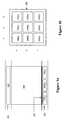
- FIG. 1 adepicts a cross-section view of a display cell of a color display device of the present invention.
- FIG. 1 bdepicts a top view of the layer comprising driving electrodes.
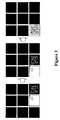
- FIGS. 2 a - 2 cillustrate how different color states may be displayed by the display cell of FIG. 1 a.
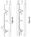
- FIG. 3illustrates how the charged pigment particles may move to the designated electrodes in steps.
- FIG. 4depicts the driving electrodes not aligned with the boundaries of the display cells.
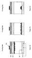
- FIG. 5 adepicts a color display of the present invention with black matrix layers on the viewing side of the display.
- FIG. 5 bdepicts a color display of the present invention with a brightness enhancement structure on the viewing side of the display.
- FIGS. 6 a - 6 gshow examples of how a brightness enhancement structure may be fabricated.
- FIG. 7 ais a three dimensional view of the brightness enhancement structure with micro-structures or micro-reflectors.
- FIG. 7 bis an alternative design of a brightness enhancement structure.
- FIGS. 8 a and 8 bshow how the black matrix layers and the micro-structure or micro-reflector are aligned with designated electrodes, respectively.
- FIGS. 9 a - 9 cdepict a color display device with black matrix layers and color filters.
- FIGS. 10 a - 10 cdepict an alternative design of color display devices.
- FIG. 1 adepicts a cross-section view of a display cell of a color display device of the present invention.
- the display cell ( 100 )is sandwiched between a first layer ( 101 ) and a second layer ( 102 ).
- the first layercomprises a common electrode ( 103 ).
- the second layercomprises more than one driving electrodes, with only 104 cx , 104 cy and 104 cz shown.
- each display cellas shown in FIG. 1 a , represents a single pixel.
- FIG. 1 bdepicts the top view of the layer comprising driving electrodes of the display cell of FIG. 1 a .
- the second layer ( 102 )comprises 3 ⁇ 3 driving electrodes, denoted as 104 ax , 104 ay , 104 az , 104 bx , 104 by , 104 bz , 104 cx , 104 cy and 104 cz . While only a 3 ⁇ 3 grid is shown, the second layer may comprise any grid which is at least 2 ⁇ 2.
- the size of the driving electrodesmay vary, depending on the size of the display cell. There is a gap between the driving electrodes. In other words, the driving electrodes are not in contact with each other.
- the driving electrode(s) intended for the charged pigment particles to gather in order to display the background color of the display cellis/are referred to as the “designated electrode(s)”.
- the multiple driving electrodes within a display cellallow the particles to migrate to one or more designated electrodes or evenly spread over all the driving electrodes.
- the 9 driving electrodes in FIG. 1 bare shown to have the same shape and size. It is understood that the shapes and sizes the driving electrodes in the same display device may vary, as long as they serve the desired functions.
- the common electrode ( 103 )is usually a transparent electrode layer (e.g., ITO), spreading over the entire top of the display device.
- the driving electrodes ( 104 s )are described in U.S. Pat. No. 7,046,228, the content of which is incorporated herein by reference in its entirety.
- the scope of the present inventionencompasses other types of electrode addressing as long as the electrodes serve the same functions.
- FIG. 1 bIt is also shown in FIG. 1 b that the 9 driving electrodes are aligned with the boundary of the display cell ( 100 ). However, for this type of color display, this feature is optional. Details of an un-aligned configuration are given below.
- the background layermay be on top of the driving electrodes (as shown) or underneath the driving electrodes (not shown).
- the layer of the driving electrodesi.e., the second layer, may also serve as the background layer.
- first layer ( 101 )is shown in most of drawings as the viewing side, it is noted that it is also possible for the second layer ( 102 ) to be on the viewing side.
- FIGS. 2 a - 2 cillustrates how different color states may be displayed by the display cell of FIG. 1 a .
- the charged pigment particlesare of the white color
- the dielectric solvent or solvent mixture in which the pigment particles are dispersedis colored (e.g., red, green, blue or other colors) and the background layer is of the black color.
- the features and associated numbers in FIGS. 2 a , 2 b and 2 care identical.
- colorreferred to in this application may be a single color, a mid-tone color or a composite color.
- driving electrode 204 cyis a designated electrode and the remaining driving electrodes on the second layer are all non-designated electrodes.
- the voltages of the common ( 203 ) and driving ( 204 ) electrodesare set at such to cause the charged white particles to migrate to be at or near the common electrode ( 203 ) and as a result, the white color (i.e., the color of the particles) is seen, from the viewing side.
- the voltages of the common ( 203 ) and driving ( 204 ) electrodesare set at such to cause the charged white particles to migrate to be at or near the driving electrodes ( 204 s ) and as a result, the color of the solvent is seen, from the viewing side.
- the voltages of the common ( 203 ) and driving ( 204 ) electrodesare set at such to cause the charged pigment particles to migrate to be at or near one of the driving electrodes (e.g., 204 cy , “designated electrode”).
- the color of the background layer ( 207 )is seen, from the viewing side.
- the number of such designated electrodesmay be more than one. In other words, there may be one or more such designated electrodes on the second layer.
- the one designated electrode or multiple designated electrodesmay be any of the driving electrodes, location wise.
- the driving electrode(s) intended for the charged pigment particles to gather in order to display the background color of the display cellis/are referred to as the “designated electrode(s)” and the driving electrodes not intended for the charged pigment particles to gather when displaying the background color are referred to as the “non-designated electrodes”.
- the migration of the charged pigment particles to the designated electrode(s)may occur all at once, that is, the voltages of the common and driving electrodes are set at such to cause the charged pigment particles to migrate to be at or near the designated electrode(s) all at once. Alternatively, the migration may take place in steps. As shown in FIG. 3 , the voltages of driving electrodes are set at such to cause the charged pigment particles to move from one driving electrode to an adjacent driving electrode one step at a time and eventually to the designated electrode(s). This driving method may prevent the charged pigment particles from being trapped at the center of one large driving electrode even though the large driving electrode has the same polarity as the pigment particles.
- the driving electrodesdo not have to be aligned with the boundary of the display cells.
- the display cellsrepresented by the dotted lines
- the driving electrodesrepresented by the solid lines
- the charged pigment particlesmay still be driven to show the desired color states.
- a scanning method or similar approachesmay be used to first determine which driving electrodes address which display cell (i.e., pixel). For those driving electrodes (shaded in FIG. 4 ) at the edges of the display cells may never be used or may be used to drive only partial areas of the driving electrodes. However, in the latter case, cross-talk may occur.
- the blocking layersmay be black matrix layers ( 505 a ), as shown in FIG. 5 a .
- the display cell ( 500 )is sandwiched between a first layer ( 501 ) comprising a common electrode ( 503 ) and a second layer ( 502 ) comprising driving electrodes ( 504 ).
- the designated electrode ( 504 cy )is shown to be located underneath the black matrix layer ( 505 a ).
- the charged pigment particles gathered at or near the designated electrode ( 504 cy )will not be seen, from the viewing side.
- the charged pigment particleshave moved to gather at or near the designated electrode(s), only the color of the background layer ( 507 ) (e.g., black) is visible, from the viewing side.
- the black matrix layermay be applied by a method such as printing, stamping, photolithography, vapor deposition or sputtering with a shadow mask.
- the optical density of the black matrixmay be higher than 0.5, preferably higher than 1.
- the thickness of the black matrixmay vary from 0.005 ⁇ m to 50 ⁇ m, preferably from 0.01 ⁇ m to 20 ⁇ m.
- a thin layer of black coating or inkmay be transferred onto the surface where the black matrix layers will appear, by an offset rubber roller or stamp.
- a photosensitive black coatingmay be coated onto the surface where the black matrix layers will appear and exposed through a photomask.
- the photosensitive black coatingmay be a positively-working or negatively-working resist.
- a positively-working resistWhen a positively-working resist is used, the photomask have openings corresponding to the areas not intended to be covered by the black matrix layer. In this case, the photosensitive black coating in the areas not intended to be covered by the black matrix layer (exposed) is removed by a developer after exposure.
- a negatively-working resistis used, the photomask should have openings corresponding to the areas intended to be covered by the black matrix layer. In this case, the photosensitive black coating in the areas not intended to be covered by the black matrix layer (unexposed) is removed by a developer after exposure.
- the solvent(s) used to apply the black coating and the developer(s) for removing the coatingshould be carefully selected so that they do not attack the layer of the display and other structural elements.
- a colorless photosensitive ink-receptive layermay be applied onto the surface where the black matrix layers will appear, followed by exposure through a photomask.
- the photomaskshould have openings corresponding to the areas intended to be covered by the black matrix layer. In this case, after exposure, the exposed areas become ink-receptive or tacky and a black matrix may be formed on the exposed areas after a black ink or toner is applied onto those areas.
- a negatively-working photosensitive ink-receptive layermay be used.
- the photomaskshould have openings corresponding to the areas not intended to be covered by the black matrix layer and after exposure, the exposed areas (which are not intended to be covered by the black matrix layer) are hardened while a black matrix layer may be formed on the unexposed areas (which are intended to be covered by the black matrix layer) after a black ink or toner is applied onto those areas.
- the black matrixmay be post cured by heat or flood exposure to improve the film integrity and physical-mechanical properties.
- the black matrixmay be applied by printing such as screen printing or offset printing, particularly waterless offset printing.
- the blocking layersmay be a brightness enhancement structure ( 508 ) comprising micro-structures or micro-reflectors ( 505 b ) on the viewing side of the display device, as shown in FIG. 5 b .
- the display cell ( 500 )is sandwiched between a first layer ( 501 ) comprising a common electrode ( 503 ) and a second layer ( 502 ) comprising driving electrodes ( 504 ).
- the designated electrode ( 504 cy )is shown to be located underneath the micro-structure or micro-reflector ( 505 b ).
- the charged pigment particles gathered at or near the designated electrode ( 504 cy )will not be seen, from the viewing side.
- the charged pigment particleshave moved to gather at or near the designated electrode(s), only the color of the background layer ( 507 ) (e.g., black) is visible, from the viewing side.
- micro-reflectorrefers to a micro-structure the surface of which is coated with a metal layer. Details of the brightness enhancement structure and how it is fabricated are given below.
- the brightness enhancement structuremay be fabricated in many different ways.
- the brightness enhancement structuremay be fabricated separately and then laminated over the viewing side of the display device.
- the brightness enhancement structuremay be fabricated by embossing as shown in FIG. 6 a .
- the embossing processis carried out at a temperature higher than the glass transition temperature of the embossable composition ( 600 ) coated on a substrate layer ( 601 ).
- the embossingis usually accomplished by a male mold which may be in the form of a roller, plate or belt.
- the embossable compositionmay comprise a thermoplastic, thermoset or a precursor thereof.
- the embossable compositionmay comprise multifunctional acrylate or methacrylate, multifunctional vinylether, multifunctional epoxide or an oligomer or polymer thereof.
- the glass transition temperatures (or Tg) for this class of materialsusually range from about ⁇ 70° C. to about 150° C., preferably from about ⁇ 20° C. to about 50° C.
- the embossing processis typically carried out at a temperature higher than the Tg.
- a heated male mold or a heated housing substrate against which the mold pressesmay be used to control the embossing temperature and pressure.
- the male moldis usually formed of a metal such as nickel.
- the moldcreates the prism-like brightness enhancement micro-structures ( 603 ) and is released during or after the embossable composition is hardened.
- the hardening of the embossable compositionmay be accomplished by cooling, solvent evaporation, cross-linking by radiation, heat or moisture.
- the cavity ( 603 )is called a micro-structure.
- the refraction index of the material for forming the brightness enhancement structureis preferably greater than about 1.4, more preferably between about 1.5 and about 1.7.
- FIG. 7 ais a three-dimensional view of a brightness enhancement structure comprising micro-structures or micro-reflectors ( 703 ).
- the brightness enhancement structure of FIG. 7 amay be referred to as a “two-dimensional” structure.
- FIG. 7 bis an alternative design of a brightness enhancement structure.
- the micro-structures or micro-reflectorsare in a continuous form and therefore the structure may be referred to as a “one-dimensional” structure.
- the brightness enhancement structuremay be used as is or further coated with a metal layer.
- the metal layer ( 607 )is then deposited over the surface ( 606 ) of the micro-structures ( 603 ) as shown in FIG. 6 b .
- Suitable metals for this stepmay include, but are not limited to, aluminum, copper, zinc, tin, molybdenum, nickel, chromium, silver, gold, iron, indium, thallium, titanium, tantalum, tungsten, rhodium, palladium, platinum and cobalt.
- Aluminumis usually preferred.
- the metal materialmust be reflective, and it may be deposited on the surface ( 606 ) of the micro-structures, using a variety of techniques such as sputtering, evaporation, roll transfer coating, electroless plating or the like.
- a strippable masking layermay be coated before metal deposition, over the surface on which the metal layer is not to be deposited. As shown in FIG. 6 c , a strippable masking layer ( 604 ) is coated onto the surface ( 605 ) between the openings of the micro-structures. The strippable masking layer is not coated on the surface ( 606 ) of the micro-structures.
- the coating of the strippable masking layermay be accomplished by a printing technique, such as flexographic printing, driographic printing, electrophotographic printing, lithographic printing, gravure printing, thermal printing, inkjet printing or screen printing.
- the coatingmay also be accomplished by a transfer-coating technique involving the use of a release layer.
- the strippable masking layerpreferably has a thickness in the range of about 0.01 to about 20 microns, more preferably about 1 to about 10 microns.
- the layeris preferably formed from a water-soluble or water-dispersible material.
- Organic materialsmay also be used.
- the strippable masking layermay be formed from a re-dispersible particulate material.
- the advantage of the re-dispersible particulate materialis that the coated layer may be easily removed without using a solubility enhancer.
- the term “re-dispersible particulate”is derived from the observation that the presence of particles in the material in a significant quantity will not decrease the stripping ability of a dried coating and, on the contrary, their presence actually enhances the stripping speed of the coated layer.
- the re-dispersible particulateconsists of particles that are surface treated to be hydrophilic through anionic, cationic or non-ionic functionalities. Their sizes are in microns, preferably in the range of about 0.1 to about 15 ⁇ m and more preferably in the range of about 0.3 to about 8 ⁇ m. Particles in these size ranges have been found to create proper surface roughness on a coated layer having a thickness of ⁇ 15 ⁇ m.
- the re-dispersible particulatemay have a surface area in the range of about 50 to about 500 m 2 /g, preferably in the range of about 200 to about 400 m 2 /g.
- the interior of the re-dispersible particulatemay also be modified to have a pore volume in the range of about 0.3 to about 3.0 ml/g, preferably in the range of about 0.7 to about 2.0 ml/g.
- re-dispersible particulatesmay include, but are not limited to, micronized silica particles, such as those of the Sylojet series or Syloid series from Grace Davison, Columbia, Md., USA.
- Non-porous nano sized water re-dispersible colloid silica particlessuch as LUDOX AM can also be used together with the micron sized particles to enhance both the surface hardness and stripping rate of the coated layer.
- organic and inorganic particleswith sufficient hydrophilicity through surface treatment, may also be suitable.
- the surface modificationcan be achieved by inorganic and organic surface modification.
- the surface treatmentprovides the dispensability of the particles in water and the re-wettability in the coated layer.
- a metal layer ( 607 )is shown to be deposited over the entire surface, including the surface ( 606 ) of the micro-structures and the surface ( 605 ) between the micro-structures.
- Suitable metal materialsare those as described above.
- the metal materialmust be reflective and may be deposited by a variety of techniques previously described.
- FIG. 6 eshows the structure after removal of the strippable masking layer ( 604 ) with the metal layer 607 coated thereon.
- This stepmay be carried out with an aqueous or non-aqueous solvent such as water, MEK, acetone, ethanol or isopropanol or the like, depending on the material used for the strippable masking layer.
- the strippable masking layermay also be removed by mechanical means, such as brushing, using a spray nozzle or peeling it off with an adhesive layer. While removing the strippable masking layer ( 604 ), the metal layer ( 607 ) deposited on the strippable masking layer is also removed, leaving the metal layer ( 607 ) only on the surface ( 606 ) of the micro-structures.
- FIGS. 6 f and 6 gdepict an alternative process for depositing the metal layer.
- a metal layer ( 607 )is deposited over the entire surface first, including both the surface ( 606 ) of the micro-structures and the surface ( 605 ) between the micro-structures.
- FIG. 6 gshows that the film of micro-structures deposited with a metal layer ( 607 ) is laminated with a film ( 617 ) coated with an adhesive layer ( 616 ).
- the metal layer ( 607 ) on top of the surface ( 605 )may be conveniently peeled off when the micro-structure film is delaminated (separated) from the adhesive layer ( 616 ) coated film ( 617 ).
- the thickness of the adhesive layer ( 616 ) on the adhesive coated filmis preferably in the range of about 1 to about 50 ⁇ m and more preferably in the range of about 2 to about 10 ⁇ m.
- the brightness enhancement structurecomprising micro-structures (uncoated with a metal layer) or micro-reflectors (coated with a metal layer) is then laminated over a layer of display cells as described above.
- FIG. 8 ashows how the black matrix layers ( 803 a ) are aligned with the designated electrodes ( 802 ) to allow the designated electrodes to be hidden from the viewer.
- the width (w 1 ) of the black matrix layer ( 803 a )must be at least equal to the width (w 2 ) of the designated electrode(s) ( 802 ). It is desirable that the width (w 1 ) of the black matrix layers is slightly greater than the width (w 2 ) of the designated electrode(s) to prevent loss of contrast when viewed at an angle.
- FIG. 8 bshows how the micro-structures or micro-reflectors ( 803 b ) are aligned with the designated electrodes to allow the designated electrodes to be hidden from the viewer.
- the width (w 3 ) of the base ( 801 ) of the micro-structure or micro-reflector ( 803 b )must be at least equal to the width (w 4 ) of the designated electrode(s) ( 802 ). It is acceptable if the width (w 3 ) of the base of the micro-structure or micro-reflector is slightly greater than the width (w 4 ) of the designated electrode(s).
- the brightness enhancement structure ( 800 )is formed of a high refractive index material, and the tilted surface ( 804 ) is reflective to the incoming light source due to the total internal reflection (TIR) phenomenon.
- TIRtotal internal reflection
- the area underneath the micro-structure or micro-reflectorwill not receive any light.
- the charged pigment particlesmigrate to those designated electrodes underneath the micro-structures or micro-reflectors, thus avoiding light leakage.
- the black matrix layers or the micro-structures or micro-reflectorsare not aligned with the designated electrodes.
- the width of the black matrix layers or the base of the microstructures or micro-reflectorsis significantly greater than the width of the designated electrodes, so that the designated electrodes may be hidden from the incoming light.
- each of the display cellshas a color filter ( 900 ).
- the charged pigment particlesmay be of the black color
- the dielectric solvent or solvent mixture in which the charged pigment particles are dispersedis clear and transparent
- the background ( 907 ) of the display cellsmay be of the white color.
- FIG. 9 athe voltages of the common ( 903 ) and driving ( 904 ) electrodes are set at such to cause the charged black particles to migrate to be at or near the common electrode and as a result, a black color (i.e., the color of the particles) is seen, from the viewing side.
- FIG. 9 bprovides an alternative way of achieving a black color.
- the voltages of the common ( 903 ) and driving ( 904 ) electrodesare set at such to cause the charged black particles to migrate to be at or near the driving electrodes and as a result, a black color is seen, from the viewing side.
- FIG. 9 bthe voltages of the common ( 903 ) and driving ( 904 ) electrodes are set at such to cause the charged black particles to migrate to be at or near the driving electrodes and as a result, a black color is seen, from the viewing side.
- the voltages of the common ( 903 ) and driving ( 904 ) electrodesare set at such to cause the charged black particles to migrate to be at or near one or more designated electrode(s).
- the charged pigment particles gathered at or near the designated electrode(s)will not be seen, from the viewing side because of the presence of the blocking layers (e.g., black matrix layers 906 ).
- the color seen from the viewing sidewould be the color of the color filter ( 900 ) as the display cell has a white background ( 907 ).
- the charged pigment particlesmay be of the white color
- the dielectric solvent or solvent mixture in which the charged pigment particles are dispersedis clear and transparent
- the background of the display cellsmay be of the black color.
- black matrix layers ( 906 ) in FIGS. 9 a - 9 cmay be replaced with a brightness enhancement structure with micro-structures or micro-reflectors.
- the white color statewill be resulted from mixing the red, green and blue colors.
- the color filters ( 900 )may be underneath the black matrix layers (as shown in FIGS. 9 a - 9 c ) or the brightness enhancement structure.
- the presence of the color filterscould cause loss of light energy.
- the black matrix layers or a brightness enhancement structurehelps to compensate the effect of such loss and provides improved on-axis brightness.
- the black matrix layers or a brightness enhancement structuremay be aligned with the dead spots and therefore the dead spots could be hidden underneath the black matrix layers or the micro-structures or micro-reflectors, thus effectively increasing the aperture ratio of the display device.
- the color filtersmay be placed on top of the black matrix layers or the brightness enhancement structure.
- FIGS. 10 a - 10 cdepict an alternative design of color display devices.
- the color display devicedoes not require black matrix layers or a brightness enhancement structure.
- the display cell ( 1000 ), in this design,is also sandwiched between a first layer ( 1001 ) and a second layer ( 1002 ).
- the first layercomprises a common electrode ( 1003 ).
- the second layercomprises more than one driving electrodes (e.g., 1004 cx , 1004 cy and 1004 cz as shown). As shown the color display device is viewed from the driving electrode side (i.e., the second layer) instead of the common electrode side (i.e., the first layer).
- the driving electrode layeralso comprises multiple driving electrodes as shown in FIG. 1 b . While only a 3 ⁇ 3 grid is shown in FIG. 1 b , the driving electrodes may be of a grid which is at least 2 ⁇ 2.
- the multiple driving electrodes within a display cellallow the particles to migrate to one or more designated electrodes or evenly spread over all the driving electrodes.
- the driving electrodesare transparent and the designated electrode(s) is/are non-transparent.
- the designated electrodesmay be opaque.
- the background layermay be on top of the common electrode (as shown) or underneath the common electrode (not shown).
- the layer of the common electrodemay also serve as the background layer.
- the charged pigment particlesare of the white color
- the dielectric solvent or solvent mixture in which the pigment particles are dispersedis colored (e.g., red, green or blue)
- the background layeris of the black color.
- the features and associated numbers in FIGS. 10 a , 10 b and 10 care identical.
- the voltages of the common ( 1003 ) and driving ( 1004 ) electrodesare set at such voltage to cause the charged white particles to migrate to be at or near the common electrode ( 1003 ) and as a result, the color of the solvent is seen through the transparent driving electrodes, from the viewing side.
- the voltages of the common ( 1003 ) and driving ( 1004 ) electrodesare set at such to cause the charged white particles to migrate to be at or near the driving electrodes ( 1004 s ) and as a result, the color of the pigment particles is seen through the transparent driving electrodes, from the viewing side.
- the voltages of the common ( 1003 ) and driving ( 1004 ) electrodesare set at such to cause the charged pigment particles to migrate to be at or near the designated electrode (e.g., 1004 cy ).
- the designated electrodee.g., 1004 cy
- the number of such designated electrodesmay be more than one. In other words, there may be one or more such designated electrodes.
- FIG. 1 bAnother aspect of the present invention provides an alternative design of FIG. 1 b .
- the driving electrodes 104 ax , 104 ay , 104 az , 104 bx , 104 bz , 104 cx , 104 cy and 104 cz in FIG. 1 bmay be connected and the connected pieces, as a whole, acts as one non-designated electrode.
- the center electrode 104 byis the designated electrode.
- This alternative designhas the advantage that there are fewer addressing points that are needed, thus reducing the complexity of the electrical circuit design.
- the one non-designated electrodemay consist any of the 9 driving electrodes connected together. The number of the designated electrode also is not limited to one.
- the designated electrodespreferably are also connected. But in any case, the connected non-designated electrode must be larger in area than the designated electrode. In addition, the designated electrode and the non-designated electrode, in this case, must be aligned with the boundary of the display cells.
Landscapes
- Physics & Mathematics (AREA)
- Nonlinear Science (AREA)
- General Physics & Mathematics (AREA)
- Optics & Photonics (AREA)
- Health & Medical Sciences (AREA)
- Life Sciences & Earth Sciences (AREA)
- Chemical & Material Sciences (AREA)
- Chemical Kinetics & Catalysis (AREA)
- Electrochemistry (AREA)
- Molecular Biology (AREA)
- Electrochromic Elements, Electrophoresis, Or Variable Reflection Or Absorption Elements (AREA)
- Liquid Crystal (AREA)
Abstract
Description
Claims (23)
Priority Applications (1)
| Application Number | Priority Date | Filing Date | Title |
|---|---|---|---|
| US12/370,485US8169690B2 (en) | 2008-02-21 | 2009-02-12 | Color display devices |
Applications Claiming Priority (2)
| Application Number | Priority Date | Filing Date | Title |
|---|---|---|---|
| US3048908P | 2008-02-21 | 2008-02-21 | |
| US12/370,485US8169690B2 (en) | 2008-02-21 | 2009-02-12 | Color display devices |
Publications (2)
| Publication Number | Publication Date |
|---|---|
| US20090213452A1 US20090213452A1 (en) | 2009-08-27 |
| US8169690B2true US8169690B2 (en) | 2012-05-01 |
Family
ID=40985875
Family Applications (1)
| Application Number | Title | Priority Date | Filing Date |
|---|---|---|---|
| US12/370,485Active2029-09-30US8169690B2 (en) | 2008-02-21 | 2009-02-12 | Color display devices |
Country Status (3)
| Country | Link |
|---|---|
| US (1) | US8169690B2 (en) |
| TW (1) | TWI400544B (en) |
| WO (1) | WO2009105385A1 (en) |
Cited By (38)
| Publication number | Priority date | Publication date | Assignee | Title |
|---|---|---|---|---|
| US20110217639A1 (en)* | 2010-03-02 | 2011-09-08 | Sprague Robert A | Electrophoretic display fluid |
| US8704756B2 (en) | 2010-05-26 | 2014-04-22 | Sipix Imaging, Inc. | Color display architecture and driving methods |
| US8717664B2 (en) | 2012-10-02 | 2014-05-06 | Sipix Imaging, Inc. | Color display device |
| US8786935B2 (en) | 2011-06-02 | 2014-07-22 | Sipix Imaging, Inc. | Color electrophoretic display |
| US8797636B2 (en) | 2012-07-17 | 2014-08-05 | Sipix Imaging, Inc. | Light-enhancing structure for electrophoretic display |
| US8810899B2 (en) | 2008-04-03 | 2014-08-19 | E Ink California, Llc | Color display devices |
| US8964282B2 (en) | 2012-10-02 | 2015-02-24 | E Ink California, Llc | Color display device |
| US8976444B2 (en) | 2011-09-02 | 2015-03-10 | E Ink California, Llc | Color display devices |
| US9013783B2 (en) | 2011-06-02 | 2015-04-21 | E Ink California, Llc | Color electrophoretic display |
| US9116412B2 (en) | 2010-05-26 | 2015-08-25 | E Ink California, Llc | Color display architecture and driving methods |
| US9140952B2 (en) | 2010-04-22 | 2015-09-22 | E Ink California, Llc | Electrophoretic display with enhanced contrast |
| US9170468B2 (en) | 2013-05-17 | 2015-10-27 | E Ink California, Llc | Color display device |
| US9251736B2 (en) | 2009-01-30 | 2016-02-02 | E Ink California, Llc | Multiple voltage level driving for electrophoretic displays |
| US9285649B2 (en) | 2013-04-18 | 2016-03-15 | E Ink California, Llc | Color display device |
| US9360733B2 (en) | 2012-10-02 | 2016-06-07 | E Ink California, Llc | Color display device |
| US9459510B2 (en) | 2013-05-17 | 2016-10-04 | E Ink California, Llc | Color display device with color filters |
| US9513527B2 (en) | 2014-01-14 | 2016-12-06 | E Ink California, Llc | Color display device |
| US9541814B2 (en) | 2014-02-19 | 2017-01-10 | E Ink California, Llc | Color display device |
| US9646547B2 (en) | 2013-05-17 | 2017-05-09 | E Ink California, Llc | Color display device |
| US9759981B2 (en) | 2014-03-18 | 2017-09-12 | E Ink California, Llc | Color display device |
| US10147366B2 (en) | 2014-11-17 | 2018-12-04 | E Ink California, Llc | Methods for driving four particle electrophoretic display |
| US10162242B2 (en) | 2013-10-11 | 2018-12-25 | E Ink California, Llc | Color display device |
| US10380955B2 (en) | 2014-07-09 | 2019-08-13 | E Ink California, Llc | Color display device and driving methods therefor |
| US10401668B2 (en) | 2012-05-30 | 2019-09-03 | E Ink California, Llc | Display device with visually-distinguishable watermark area and non-watermark area |
| US10514583B2 (en) | 2011-01-31 | 2019-12-24 | E Ink California, Llc | Color electrophoretic display |
| WO2020033175A1 (en) | 2018-08-10 | 2020-02-13 | E Ink California, Llc | Switchable light-collimating layer including bistable electrophoretic fluid |
| WO2020033787A1 (en) | 2018-08-10 | 2020-02-13 | E Ink California, Llc | Driving waveforms for switchable light-collimating layer including bistable electrophoretic fluid |
| US10698265B1 (en) | 2017-10-06 | 2020-06-30 | E Ink California, Llc | Quantum dot film |
| US10802373B1 (en) | 2017-06-26 | 2020-10-13 | E Ink Corporation | Reflective microcells for electrophoretic displays and methods of making the same |
| US10891906B2 (en) | 2014-07-09 | 2021-01-12 | E Ink California, Llc | Color display device and driving methods therefor |
| US10921676B2 (en) | 2017-08-30 | 2021-02-16 | E Ink Corporation | Electrophoretic medium |
| US11017705B2 (en) | 2012-10-02 | 2021-05-25 | E Ink California, Llc | Color display device including multiple pixels for driving three-particle electrophoretic media |
| US11266832B2 (en) | 2017-11-14 | 2022-03-08 | E Ink California, Llc | Electrophoretic active delivery system including porous conductive electrode layer |
| US11314098B2 (en) | 2018-08-10 | 2022-04-26 | E Ink California, Llc | Switchable light-collimating layer with reflector |
| US11938215B2 (en) | 2019-11-27 | 2024-03-26 | E Ink Corporation | Method for operating a benefit agent delivery system comprising microcells having an electrically eroding sealing layer |
| WO2025147410A2 (en) | 2024-01-02 | 2025-07-10 | E Ink Corporation | Electrophoretic media comprising a cationic charge control agent |
| WO2025147504A1 (en) | 2024-01-05 | 2025-07-10 | E Ink Corporation | An electrophoretic medium comprising particles having a pigment core and a polymeric shell |
| WO2025151355A1 (en) | 2024-01-08 | 2025-07-17 | E Ink Corporation | Electrophoretic device having an adhesive layer comprising conductive filler particles and a polymeric dispersant |
Families Citing this family (12)
| Publication number | Priority date | Publication date | Assignee | Title |
|---|---|---|---|---|
| WO2009134889A1 (en)* | 2008-05-01 | 2009-11-05 | Sipix Imaging, Inc. | Color display devices |
| CN102138094B (en)* | 2008-09-02 | 2015-07-29 | 希毕克斯影像有限公司 | Color display apparatus |
| US8797258B2 (en)* | 2008-12-30 | 2014-08-05 | Sipix Imaging, Inc. | Highlight color display architecture using enhanced dark state |
| US8503063B2 (en) | 2008-12-30 | 2013-08-06 | Sipix Imaging, Inc. | Multicolor display architecture using enhanced dark state |
| US8976107B2 (en) | 2009-12-15 | 2015-03-10 | Sharp Kabushiki Kaisha | Display element and electrical device using the same |
| US8184357B2 (en) | 2010-06-15 | 2012-05-22 | Hewlett-Packard Development Company, L.P. | Display element |
| TWI455088B (en)* | 2010-07-08 | 2014-10-01 | Sipix Imaging Inc | Three dimensional driving scheme for electrophoretic display devices |
| WO2012026161A1 (en)* | 2010-08-27 | 2012-03-01 | シャープ株式会社 | Display element and electrical apparatus using same |
| US8670174B2 (en) | 2010-11-30 | 2014-03-11 | Sipix Imaging, Inc. | Electrophoretic display fluid |
| US9146439B2 (en) | 2011-01-31 | 2015-09-29 | E Ink California, Llc | Color electrophoretic display |
| US8649084B2 (en) | 2011-09-02 | 2014-02-11 | Sipix Imaging, Inc. | Color display devices |
| US8917439B2 (en) | 2012-02-09 | 2014-12-23 | E Ink California, Llc | Shutter mode for color display devices |
Citations (43)
| Publication number | Priority date | Publication date | Assignee | Title |
|---|---|---|---|---|
| US3892568A (en) | 1969-04-23 | 1975-07-01 | Matsushita Electric Industrial Co Ltd | Electrophoretic image reproduction process |
| US4298448A (en) | 1979-02-02 | 1981-11-03 | Bbc Brown, Boveri & Company, Limited | Electrophoretic display |
| US5378574A (en) | 1988-08-17 | 1995-01-03 | Xerox Corporation | Inks and liquid developers containing colored silica particles |
| WO1999053373A1 (en) | 1998-04-10 | 1999-10-21 | E-Ink Corporation | Full color reflective display with multichromatic sub-pixels |
| US5980719A (en) | 1997-05-13 | 1999-11-09 | Sarnoff Corporation | Electrohydrodynamic receptor |
| US6198809B1 (en) | 1996-04-25 | 2001-03-06 | Copytele Inc. | Multi-functional personal telecommunications apparatus |
| EP1089118A2 (en) | 1999-10-01 | 2001-04-04 | Lucent Technologies Inc. | Electrophoretic display and method of making the same |
| US20020033792A1 (en) | 2000-08-31 | 2002-03-21 | Satoshi Inoue | Electrophoretic display |
| US6373461B1 (en) | 1999-01-29 | 2002-04-16 | Seiko Epson Corporation | Piezoelectric transducer and electrophoretic ink display apparatus using piezoelectric transducer |
| US20020171620A1 (en) | 2001-05-18 | 2002-11-21 | International Business Machines Corporation | Transmissive electrophoretic display with stacked color cells |
| US6486866B1 (en) | 1998-11-04 | 2002-11-26 | Sony Corporation | Display device and method of driving the same |
| US20030002132A1 (en) | 2001-05-24 | 2003-01-02 | Xerox Corporation | Photochromic electrophoretic ink display |
| WO2003016993A1 (en) | 2001-08-17 | 2003-02-27 | Sipix Imaging, Inc. | Electrophoretic display with dual-mode switching |
| US6538801B2 (en) | 1996-07-19 | 2003-03-25 | E Ink Corporation | Electrophoretic displays using nanoparticles |
| US20030095094A1 (en) | 2000-04-13 | 2003-05-22 | Canon Kabushiki Kaisha | Electrophoretic display method and device |
| US20030107631A1 (en) | 2001-05-09 | 2003-06-12 | Canon Kabushiki Kaisha | Recording, method, recording apparatus, method for manufacturing recorded article, and recorded article |
| US20030132908A1 (en) | 1999-05-03 | 2003-07-17 | Herb Craig A. | Electrophoretic ink composed of particles with field dependent mobilities |
| US6693620B1 (en) | 1999-05-03 | 2004-02-17 | E Ink Corporation | Threshold addressing of electrophoretic displays |
| US6704133B2 (en) | 1998-03-18 | 2004-03-09 | E-Ink Corporation | Electro-optic display overlays and systems for addressing such displays |
| US20040051935A1 (en) | 2000-06-22 | 2004-03-18 | Seiko Epson Corporation | Method and circuit for driving electrophoretic display and electronic device using same |
| US6724521B2 (en)* | 2001-03-21 | 2004-04-20 | Kabushiki Kaisha Toshiba | Electrophoresis display device |
| US20040113884A1 (en) | 1995-07-20 | 2004-06-17 | E Ink Corporation | Electrostatically addressable electrophoretic display |
| US20040136048A1 (en) | 1995-07-20 | 2004-07-15 | E Ink Corporation | Dielectrophoretic displays |
| US6788449B2 (en) | 2000-03-03 | 2004-09-07 | Sipix Imaging, Inc. | Electrophoretic display and novel process for its manufacture |
| US20040263947A1 (en) | 1998-04-10 | 2004-12-30 | Paul Drzaic | Full color reflective display with multichromatic sub-pixels |
| US20050151709A1 (en)* | 2003-10-08 | 2005-07-14 | E Ink Corporation | Electro-wetting displays |
| US20050190431A1 (en) | 2004-01-27 | 2005-09-01 | Canon Kabushiki Kaisha | Display apparatus and driving method thereof |
| US7009756B2 (en)* | 1999-01-08 | 2006-03-07 | Canon Kabushiki Kaisha | Electrophoretic display device |
| US7038670B2 (en) | 2002-08-16 | 2006-05-02 | Sipix Imaging, Inc. | Electrophoretic display with dual mode switching |
| US7050218B2 (en) | 2003-06-24 | 2006-05-23 | Seiko Epson Corporation | Electrophoretic dispersion, electrophoretic display device, method of manufacturing electrophoretic display device, and electronic system |
| JP2007013682A (en)* | 2005-06-30 | 2007-01-18 | Epson Toyocom Corp | Surface acoustic wave device |
| US7283199B2 (en) | 2004-09-17 | 2007-10-16 | Canon Kabushiki Kaisha | Exposure apparatus, and device manufacturing method |
| US7365732B2 (en) | 2002-05-13 | 2008-04-29 | Canon Kabushiki Kaisha | Display device employing electrophoretic migration |
| US7417787B2 (en) | 2006-05-19 | 2008-08-26 | Xerox Corporation | Electrophoretic display device |
| WO2008122927A1 (en) | 2007-04-06 | 2008-10-16 | Koninklijke Philips Electronics N.V. | Reflective display and method for manufacturing such a display |
| US20090034054A1 (en)* | 2005-07-29 | 2009-02-05 | Dai Nippon Printing Co., Ltd. | Display device, its manufacturing method, and display medium |
| US7545557B2 (en) | 2006-10-30 | 2009-06-09 | Xerox Corporation | Color display device |
| US7548291B2 (en) | 2003-11-12 | 2009-06-16 | Lg Display Lcd Co., Ltd. | Reflective type liquid crystal display device and fabrication method thereof |
| WO2009124142A2 (en) | 2008-04-03 | 2009-10-08 | Sipix Imaging, Inc. | Color display devices |
| US20090273827A1 (en) | 2008-05-01 | 2009-11-05 | Craig Lin | Color display devices |
| US20100053728A1 (en) | 2008-09-02 | 2010-03-04 | Craig Lin | Color display devices |
| US20100165005A1 (en) | 2008-12-30 | 2010-07-01 | Sprague Robert A | Highlight color display architecture using enhanced dark state |
| US20100165448A1 (en) | 2008-12-30 | 2010-07-01 | Sprague Robert A | Multicolor display architecture using enhanced dark state |
Family Cites Families (3)
| Publication number | Priority date | Publication date | Assignee | Title |
|---|---|---|---|---|
| JP4250407B2 (en)* | 2002-11-25 | 2009-04-08 | キヤノン株式会社 | Image forming system |
| CN100538492C (en)* | 2005-07-29 | 2009-09-09 | 大日本印刷株式会社 | Display device, its manufacture method and display medium |
| US7808696B2 (en)* | 2006-07-31 | 2010-10-05 | Samsung Electronics Co., Ltd. | Electrophoretic display device and fabrication thereof |
- 2009
- 2009-02-12USUS12/370,485patent/US8169690B2/enactiveActive
- 2009-02-12WOPCT/US2009/033954patent/WO2009105385A1/enactiveApplication Filing
- 2009-02-16TWTW098104806Apatent/TWI400544B/enactive
Patent Citations (52)
| Publication number | Priority date | Publication date | Assignee | Title |
|---|---|---|---|---|
| US3892568A (en) | 1969-04-23 | 1975-07-01 | Matsushita Electric Industrial Co Ltd | Electrophoretic image reproduction process |
| US4298448A (en) | 1979-02-02 | 1981-11-03 | Bbc Brown, Boveri & Company, Limited | Electrophoretic display |
| US5378574A (en) | 1988-08-17 | 1995-01-03 | Xerox Corporation | Inks and liquid developers containing colored silica particles |
| US20040113884A1 (en) | 1995-07-20 | 2004-06-17 | E Ink Corporation | Electrostatically addressable electrophoretic display |
| US20040136048A1 (en) | 1995-07-20 | 2004-07-15 | E Ink Corporation | Dielectrophoretic displays |
| US6198809B1 (en) | 1996-04-25 | 2001-03-06 | Copytele Inc. | Multi-functional personal telecommunications apparatus |
| US6538801B2 (en) | 1996-07-19 | 2003-03-25 | E Ink Corporation | Electrophoretic displays using nanoparticles |
| US5980719A (en) | 1997-05-13 | 1999-11-09 | Sarnoff Corporation | Electrohydrodynamic receptor |
| US6704133B2 (en) | 1998-03-18 | 2004-03-09 | E-Ink Corporation | Electro-optic display overlays and systems for addressing such displays |
| US6864875B2 (en) | 1998-04-10 | 2005-03-08 | E Ink Corporation | Full color reflective display with multichromatic sub-pixels |
| US20040263947A1 (en) | 1998-04-10 | 2004-12-30 | Paul Drzaic | Full color reflective display with multichromatic sub-pixels |
| US7075502B1 (en) | 1998-04-10 | 2006-07-11 | E Ink Corporation | Full color reflective display with multichromatic sub-pixels |
| WO1999053373A1 (en) | 1998-04-10 | 1999-10-21 | E-Ink Corporation | Full color reflective display with multichromatic sub-pixels |
| US6486866B1 (en) | 1998-11-04 | 2002-11-26 | Sony Corporation | Display device and method of driving the same |
| US7009756B2 (en)* | 1999-01-08 | 2006-03-07 | Canon Kabushiki Kaisha | Electrophoretic display device |
| US6373461B1 (en) | 1999-01-29 | 2002-04-16 | Seiko Epson Corporation | Piezoelectric transducer and electrophoretic ink display apparatus using piezoelectric transducer |
| US7038655B2 (en) | 1999-05-03 | 2006-05-02 | E Ink Corporation | Electrophoretic ink composed of particles with field dependent mobilities |
| US20030132908A1 (en) | 1999-05-03 | 2003-07-17 | Herb Craig A. | Electrophoretic ink composed of particles with field dependent mobilities |
| US6693620B1 (en) | 1999-05-03 | 2004-02-17 | E Ink Corporation | Threshold addressing of electrophoretic displays |
| US6337761B1 (en) | 1999-10-01 | 2002-01-08 | Lucent Technologies Inc. | Electrophoretic display and method of making the same |
| EP1089118A2 (en) | 1999-10-01 | 2001-04-04 | Lucent Technologies Inc. | Electrophoretic display and method of making the same |
| US6788449B2 (en) | 2000-03-03 | 2004-09-07 | Sipix Imaging, Inc. | Electrophoretic display and novel process for its manufacture |
| US20030095094A1 (en) | 2000-04-13 | 2003-05-22 | Canon Kabushiki Kaisha | Electrophoretic display method and device |
| US20040051935A1 (en) | 2000-06-22 | 2004-03-18 | Seiko Epson Corporation | Method and circuit for driving electrophoretic display and electronic device using same |
| US20020033792A1 (en) | 2000-08-31 | 2002-03-21 | Satoshi Inoue | Electrophoretic display |
| US6724521B2 (en)* | 2001-03-21 | 2004-04-20 | Kabushiki Kaisha Toshiba | Electrophoresis display device |
| US6729718B2 (en) | 2001-05-09 | 2004-05-04 | Canon Kabushiki Kaisha | Recording method, recording apparatus, method for manufacturing recorded article, and recorded article |
| US20030107631A1 (en) | 2001-05-09 | 2003-06-12 | Canon Kabushiki Kaisha | Recording, method, recording apparatus, method for manufacturing recorded article, and recorded article |
| US20020171620A1 (en) | 2001-05-18 | 2002-11-21 | International Business Machines Corporation | Transmissive electrophoretic display with stacked color cells |
| US20030002132A1 (en) | 2001-05-24 | 2003-01-02 | Xerox Corporation | Photochromic electrophoretic ink display |
| US7046228B2 (en) | 2001-08-17 | 2006-05-16 | Sipix Imaging, Inc. | Electrophoretic display with dual mode switching |
| WO2003016993A1 (en) | 2001-08-17 | 2003-02-27 | Sipix Imaging, Inc. | Electrophoretic display with dual-mode switching |
| US7365732B2 (en) | 2002-05-13 | 2008-04-29 | Canon Kabushiki Kaisha | Display device employing electrophoretic migration |
| US7038670B2 (en) | 2002-08-16 | 2006-05-02 | Sipix Imaging, Inc. | Electrophoretic display with dual mode switching |
| US7050218B2 (en) | 2003-06-24 | 2006-05-23 | Seiko Epson Corporation | Electrophoretic dispersion, electrophoretic display device, method of manufacturing electrophoretic display device, and electronic system |
| US20050151709A1 (en)* | 2003-10-08 | 2005-07-14 | E Ink Corporation | Electro-wetting displays |
| US7548291B2 (en) | 2003-11-12 | 2009-06-16 | Lg Display Lcd Co., Ltd. | Reflective type liquid crystal display device and fabrication method thereof |
| US20050190431A1 (en) | 2004-01-27 | 2005-09-01 | Canon Kabushiki Kaisha | Display apparatus and driving method thereof |
| US7283199B2 (en) | 2004-09-17 | 2007-10-16 | Canon Kabushiki Kaisha | Exposure apparatus, and device manufacturing method |
| JP2007013682A (en)* | 2005-06-30 | 2007-01-18 | Epson Toyocom Corp | Surface acoustic wave device |
| US20090034054A1 (en)* | 2005-07-29 | 2009-02-05 | Dai Nippon Printing Co., Ltd. | Display device, its manufacturing method, and display medium |
| US7417787B2 (en) | 2006-05-19 | 2008-08-26 | Xerox Corporation | Electrophoretic display device |
| US7545557B2 (en) | 2006-10-30 | 2009-06-09 | Xerox Corporation | Color display device |
| WO2008122927A1 (en) | 2007-04-06 | 2008-10-16 | Koninklijke Philips Electronics N.V. | Reflective display and method for manufacturing such a display |
| WO2009124142A2 (en) | 2008-04-03 | 2009-10-08 | Sipix Imaging, Inc. | Color display devices |
| US20090251763A1 (en) | 2008-04-03 | 2009-10-08 | Sprague Robert A | Color display devices |
| US20090273827A1 (en) | 2008-05-01 | 2009-11-05 | Craig Lin | Color display devices |
| WO2009134889A1 (en) | 2008-05-01 | 2009-11-05 | Sipix Imaging, Inc. | Color display devices |
| US20100053728A1 (en) | 2008-09-02 | 2010-03-04 | Craig Lin | Color display devices |
| WO2010027810A1 (en) | 2008-09-02 | 2010-03-11 | Sipix Imaging, Inc. | Color display devices |
| US20100165005A1 (en) | 2008-12-30 | 2010-07-01 | Sprague Robert A | Highlight color display architecture using enhanced dark state |
| US20100165448A1 (en) | 2008-12-30 | 2010-07-01 | Sprague Robert A | Multicolor display architecture using enhanced dark state |
Non-Patent Citations (3)
| Title |
|---|
| International Search Report for PCT/US09/33954, mailed Apr. 6, 2009. |
| U.S. Appl. No. 13/038,255, filed Mar. 1, 2011, Sprague. |
| U.S. Appl. No. 13/092,052, filed Apr. 21, 2011, Sprague et al. |
Cited By (54)
| Publication number | Priority date | Publication date | Assignee | Title |
|---|---|---|---|---|
| US8810899B2 (en) | 2008-04-03 | 2014-08-19 | E Ink California, Llc | Color display devices |
| US9251736B2 (en) | 2009-01-30 | 2016-02-02 | E Ink California, Llc | Multiple voltage level driving for electrophoretic displays |
| US20110217639A1 (en)* | 2010-03-02 | 2011-09-08 | Sprague Robert A | Electrophoretic display fluid |
| US9140952B2 (en) | 2010-04-22 | 2015-09-22 | E Ink California, Llc | Electrophoretic display with enhanced contrast |
| US8704756B2 (en) | 2010-05-26 | 2014-04-22 | Sipix Imaging, Inc. | Color display architecture and driving methods |
| US9116412B2 (en) | 2010-05-26 | 2015-08-25 | E Ink California, Llc | Color display architecture and driving methods |
| US10514583B2 (en) | 2011-01-31 | 2019-12-24 | E Ink California, Llc | Color electrophoretic display |
| US9013783B2 (en) | 2011-06-02 | 2015-04-21 | E Ink California, Llc | Color electrophoretic display |
| US8786935B2 (en) | 2011-06-02 | 2014-07-22 | Sipix Imaging, Inc. | Color electrophoretic display |
| US8976444B2 (en) | 2011-09-02 | 2015-03-10 | E Ink California, Llc | Color display devices |
| US10401668B2 (en) | 2012-05-30 | 2019-09-03 | E Ink California, Llc | Display device with visually-distinguishable watermark area and non-watermark area |
| US10831052B2 (en) | 2012-05-30 | 2020-11-10 | E Ink California, Llc | Display device with visually-distinguishable watermark area and non-watermark area |
| US8797636B2 (en) | 2012-07-17 | 2014-08-05 | Sipix Imaging, Inc. | Light-enhancing structure for electrophoretic display |
| US9360733B2 (en) | 2012-10-02 | 2016-06-07 | E Ink California, Llc | Color display device |
| US8717664B2 (en) | 2012-10-02 | 2014-05-06 | Sipix Imaging, Inc. | Color display device |
| US8964282B2 (en) | 2012-10-02 | 2015-02-24 | E Ink California, Llc | Color display device |
| US11017705B2 (en) | 2012-10-02 | 2021-05-25 | E Ink California, Llc | Color display device including multiple pixels for driving three-particle electrophoretic media |
| US9285649B2 (en) | 2013-04-18 | 2016-03-15 | E Ink California, Llc | Color display device |
| US9459510B2 (en) | 2013-05-17 | 2016-10-04 | E Ink California, Llc | Color display device with color filters |
| US9170468B2 (en) | 2013-05-17 | 2015-10-27 | E Ink California, Llc | Color display device |
| US9646547B2 (en) | 2013-05-17 | 2017-05-09 | E Ink California, Llc | Color display device |
| US10162242B2 (en) | 2013-10-11 | 2018-12-25 | E Ink California, Llc | Color display device |
| US10234742B2 (en) | 2014-01-14 | 2019-03-19 | E Ink California, Llc | Color display device |
| US10036931B2 (en) | 2014-01-14 | 2018-07-31 | E Ink California, Llc | Color display device |
| US9513527B2 (en) | 2014-01-14 | 2016-12-06 | E Ink California, Llc | Color display device |
| US9541814B2 (en) | 2014-02-19 | 2017-01-10 | E Ink California, Llc | Color display device |
| US9759981B2 (en) | 2014-03-18 | 2017-09-12 | E Ink California, Llc | Color display device |
| US10891906B2 (en) | 2014-07-09 | 2021-01-12 | E Ink California, Llc | Color display device and driving methods therefor |
| US10380955B2 (en) | 2014-07-09 | 2019-08-13 | E Ink California, Llc | Color display device and driving methods therefor |
| US11315505B2 (en) | 2014-07-09 | 2022-04-26 | E Ink California, Llc | Color display device and driving methods therefor |
| US10147366B2 (en) | 2014-11-17 | 2018-12-04 | E Ink California, Llc | Methods for driving four particle electrophoretic display |
| US10431168B2 (en) | 2014-11-17 | 2019-10-01 | E Ink California, Llc | Methods for driving four particle electrophoretic display |
| US10586499B2 (en) | 2014-11-17 | 2020-03-10 | E Ink California, Llc | Electrophoretic display including four particles with different charges and optical characteristics |
| US10891907B2 (en) | 2014-11-17 | 2021-01-12 | E Ink California, Llc | Electrophoretic display including four particles with different charges and optical characteristics |
| US10802373B1 (en) | 2017-06-26 | 2020-10-13 | E Ink Corporation | Reflective microcells for electrophoretic displays and methods of making the same |
| US11774827B2 (en) | 2017-06-26 | 2023-10-03 | E Ink Corporation | Reflective microcells for electrophoretic displays and methods of making the same |
| US11372306B2 (en) | 2017-06-26 | 2022-06-28 | E Ink Corporation | Reflective microcells for electrophoretic displays and methods of making the same |
| US10921676B2 (en) | 2017-08-30 | 2021-02-16 | E Ink Corporation | Electrophoretic medium |
| US11977310B2 (en) | 2017-08-30 | 2024-05-07 | E Ink Corporation | Electrophoretic medium |
| US10698265B1 (en) | 2017-10-06 | 2020-06-30 | E Ink California, Llc | Quantum dot film |
| US11493805B2 (en) | 2017-10-06 | 2022-11-08 | E Ink California, Llc | Quantum dot film with sealed microcells |
| US11266832B2 (en) | 2017-11-14 | 2022-03-08 | E Ink California, Llc | Electrophoretic active delivery system including porous conductive electrode layer |
| US11314098B2 (en) | 2018-08-10 | 2022-04-26 | E Ink California, Llc | Switchable light-collimating layer with reflector |
| US11435606B2 (en) | 2018-08-10 | 2022-09-06 | E Ink California, Llc | Driving waveforms for switchable light-collimating layer including bistable electrophoretic fluid |
| US11397366B2 (en) | 2018-08-10 | 2022-07-26 | E Ink California, Llc | Switchable light-collimating layer including bistable electrophoretic fluid |
| US11656526B2 (en) | 2018-08-10 | 2023-05-23 | E Ink California, Llc | Switchable light-collimating layer including bistable electrophoretic fluid |
| US11719953B2 (en) | 2018-08-10 | 2023-08-08 | E Ink California, Llc | Switchable light-collimating layer with reflector |
| WO2020033175A1 (en) | 2018-08-10 | 2020-02-13 | E Ink California, Llc | Switchable light-collimating layer including bistable electrophoretic fluid |
| WO2020033787A1 (en) | 2018-08-10 | 2020-02-13 | E Ink California, Llc | Driving waveforms for switchable light-collimating layer including bistable electrophoretic fluid |
| US11938215B2 (en) | 2019-11-27 | 2024-03-26 | E Ink Corporation | Method for operating a benefit agent delivery system comprising microcells having an electrically eroding sealing layer |
| US11938214B2 (en) | 2019-11-27 | 2024-03-26 | E Ink Corporation | Benefit agent delivery system comprising microcells having an electrically eroding sealing layer |
| WO2025147410A2 (en) | 2024-01-02 | 2025-07-10 | E Ink Corporation | Electrophoretic media comprising a cationic charge control agent |
| WO2025147504A1 (en) | 2024-01-05 | 2025-07-10 | E Ink Corporation | An electrophoretic medium comprising particles having a pigment core and a polymeric shell |
| WO2025151355A1 (en) | 2024-01-08 | 2025-07-17 | E Ink Corporation | Electrophoretic device having an adhesive layer comprising conductive filler particles and a polymeric dispersant |
Also Published As
| Publication number | Publication date |
|---|---|
| US20090213452A1 (en) | 2009-08-27 |
| WO2009105385A1 (en) | 2009-08-27 |
| TWI400544B (en) | 2013-07-01 |
| TW200951599A (en) | 2009-12-16 |
Similar Documents
| Publication | Publication Date | Title |
|---|---|---|
| US8169690B2 (en) | Color display devices | |
| US8072675B2 (en) | Color display devices | |
| US8422116B2 (en) | Color display devices | |
| US7830592B1 (en) | Display devices having micro-reflectors | |
| US7301693B2 (en) | Direct drive display with a multi-layer backplane and process for its manufacture | |
| US10444591B2 (en) | Electro-optic media produced using ink jet printing | |
| US9025234B2 (en) | Luminance enhancement structure with varying pitches | |
| US10527880B2 (en) | Process for the production of electro-optic displays, and color filters for use therein | |
| US7304780B2 (en) | Backplane design for display panels and processes for their manufacture | |
| US8714780B2 (en) | Display devices with grooved luminance enhancement film | |
| JP2019144568A (en) | Methods for sealing microcell containers with phenethylamine mixtures | |
| US20180088429A1 (en) | Color Electronic Paper and Manufacturing Method Thereof | |
| JP5187644B2 (en) | Black matrix printing method and apparatus | |
| CN1866093A (en) | Liquid crystal display device and method of manufacture thereof | |
| JP4797282B2 (en) | Manufacturing method of display panel | |
| JP3927897B2 (en) | Manufacturing method of display element | |
| JP2019028229A (en) | Display device and method for manufacturing display device | |
| TW201237528A (en) | Electrophoretic color display media panel |
Legal Events
| Date | Code | Title | Description |
|---|---|---|---|
| AS | Assignment | Owner name:SIPIX IMAGING, INC., CALIFORNIA Free format text:ASSIGNMENT OF ASSIGNORS INTEREST;ASSIGNORS:LIN, CRAIG;SPRAGUE, ROBERT A.;REEL/FRAME:022465/0104;SIGNING DATES FROM 20090311 TO 20090312 Owner name:SIPIX IMAGING, INC., CALIFORNIA Free format text:ASSIGNMENT OF ASSIGNORS INTEREST;ASSIGNORS:LIN, CRAIG;SPRAGUE, ROBERT A.;SIGNING DATES FROM 20090311 TO 20090312;REEL/FRAME:022465/0104 | |
| STCF | Information on status: patent grant | Free format text:PATENTED CASE | |
| AS | Assignment | Owner name:E INK CALIFORNIA, LLC, CALIFORNIA Free format text:CHANGE OF NAME;ASSIGNOR:SIPIX IMAGING, INC.;REEL/FRAME:033280/0408 Effective date:20140701 | |
| FPAY | Fee payment | Year of fee payment:4 | |
| MAFP | Maintenance fee payment | Free format text:PAYMENT OF MAINTENANCE FEE, 8TH YEAR, LARGE ENTITY (ORIGINAL EVENT CODE: M1552); ENTITY STATUS OF PATENT OWNER: LARGE ENTITY Year of fee payment:8 | |
| AS | Assignment | Owner name:E INK CORPORATION, MASSACHUSETTS Free format text:ASSIGNMENT OF ASSIGNORS INTEREST;ASSIGNOR:E INK CALIFORNIA, LLC;REEL/FRAME:065154/0965 Effective date:20230925 | |
| MAFP | Maintenance fee payment | Free format text:PAYMENT OF MAINTENANCE FEE, 12TH YEAR, LARGE ENTITY (ORIGINAL EVENT CODE: M1553); ENTITY STATUS OF PATENT OWNER: LARGE ENTITY Year of fee payment:12 |