US8169306B2 - Touch panel assembly with haptic effects and method of manufacturing thereof - Google Patents
Touch panel assembly with haptic effects and method of manufacturing thereofDownload PDFInfo
- Publication number
- US8169306B2 US8169306B2US12/408,824US40882409AUS8169306B2US 8169306 B2US8169306 B2US 8169306B2US 40882409 AUS40882409 AUS 40882409AUS 8169306 B2US8169306 B2US 8169306B2
- Authority
- US
- United States
- Prior art keywords
- haptic effect
- flexible arm
- touch panel
- effect generator
- arm portion
- Prior art date
- Legal status (The legal status is an assumption and is not a legal conclusion. Google has not performed a legal analysis and makes no representation as to the accuracy of the status listed.)
- Active - Reinstated, expires
Links
Images


Classifications
- H—ELECTRICITY
- H03—ELECTRONIC CIRCUITRY
- H03K—PULSE TECHNIQUE
- H03K17/00—Electronic switching or gating, i.e. not by contact-making and –breaking
- H03K17/94—Electronic switching or gating, i.e. not by contact-making and –breaking characterised by the way in which the control signals are generated
- H03K17/96—Touch switches
- G—PHYSICS
- G06—COMPUTING OR CALCULATING; COUNTING
- G06F—ELECTRIC DIGITAL DATA PROCESSING
- G06F3/00—Input arrangements for transferring data to be processed into a form capable of being handled by the computer; Output arrangements for transferring data from processing unit to output unit, e.g. interface arrangements
- G06F3/01—Input arrangements or combined input and output arrangements for interaction between user and computer
- G06F3/016—Input arrangements with force or tactile feedback as computer generated output to the user
- G—PHYSICS
- G06—COMPUTING OR CALCULATING; COUNTING
- G06F—ELECTRIC DIGITAL DATA PROCESSING
- G06F3/00—Input arrangements for transferring data to be processed into a form capable of being handled by the computer; Output arrangements for transferring data from processing unit to output unit, e.g. interface arrangements
- G06F3/01—Input arrangements or combined input and output arrangements for interaction between user and computer
- G06F3/03—Arrangements for converting the position or the displacement of a member into a coded form
- G06F3/041—Digitisers, e.g. for touch screens or touch pads, characterised by the transducing means
- G06F3/0412—Digitisers structurally integrated in a display
- G—PHYSICS
- G06—COMPUTING OR CALCULATING; COUNTING
- G06F—ELECTRIC DIGITAL DATA PROCESSING
- G06F3/00—Input arrangements for transferring data to be processed into a form capable of being handled by the computer; Output arrangements for transferring data from processing unit to output unit, e.g. interface arrangements
- G06F3/01—Input arrangements or combined input and output arrangements for interaction between user and computer
- G06F3/048—Interaction techniques based on graphical user interfaces [GUI]
- G06F3/0487—Interaction techniques based on graphical user interfaces [GUI] using specific features provided by the input device, e.g. functions controlled by the rotation of a mouse with dual sensing arrangements, or of the nature of the input device, e.g. tap gestures based on pressure sensed by a digitiser
- G06F3/0488—Interaction techniques based on graphical user interfaces [GUI] using specific features provided by the input device, e.g. functions controlled by the rotation of a mouse with dual sensing arrangements, or of the nature of the input device, e.g. tap gestures based on pressure sensed by a digitiser using a touch-screen or digitiser, e.g. input of commands through traced gestures
- G06F3/04886—Interaction techniques based on graphical user interfaces [GUI] using specific features provided by the input device, e.g. functions controlled by the rotation of a mouse with dual sensing arrangements, or of the nature of the input device, e.g. tap gestures based on pressure sensed by a digitiser using a touch-screen or digitiser, e.g. input of commands through traced gestures by partitioning the display area of the touch-screen or the surface of the digitising tablet into independently controllable areas, e.g. virtual keyboards or menus
- H—ELECTRICITY
- H03—ELECTRONIC CIRCUITRY
- H03K—PULSE TECHNIQUE
- H03K2217/00—Indexing scheme related to electronic switching or gating, i.e. not by contact-making or -breaking covered by H03K17/00
- H03K2217/94—Indexing scheme related to electronic switching or gating, i.e. not by contact-making or -breaking covered by H03K17/00 characterised by the way in which the control signal is generated
- H03K2217/96—Touch switches
- H03K2217/96062—Touch switches with tactile or haptic feedback
- Y—GENERAL TAGGING OF NEW TECHNOLOGICAL DEVELOPMENTS; GENERAL TAGGING OF CROSS-SECTIONAL TECHNOLOGIES SPANNING OVER SEVERAL SECTIONS OF THE IPC; TECHNICAL SUBJECTS COVERED BY FORMER USPC CROSS-REFERENCE ART COLLECTIONS [XRACs] AND DIGESTS
- Y10—TECHNICAL SUBJECTS COVERED BY FORMER USPC
- Y10T—TECHNICAL SUBJECTS COVERED BY FORMER US CLASSIFICATION
- Y10T29/00—Metal working
- Y10T29/49—Method of mechanical manufacture
- Y10T29/49826—Assembling or joining
Definitions
- the inventionrelates to systems with haptic effects.
- the inventionrelates to touch panels with haptic feedback.
- a personhas to adjust various functions and operations of several different electrical and mechanical devices.
- the driver of a car while drivingmay have to adjust or control a heating and cooling system, an audio entertainment system, windows, locks, a cruise control system and possibly a navigation system.
- the userwould use buttons, switches, knobs, and other similar mechanical controls to adjust the various functions or operations of these devices.
- buttons, switches, knobs, and other similar mechanical controlsto adjust the various functions or operations of these devices.
- a personmay be required to provide many different inputs through several different buttons, switches, knobs, and other mechanical controls.
- a single aggregate instrumentthat can relay commands to several devices is often employed, such as a touch panel.
- a touch panelBy using a touch panel, the user can adjust several different devices by interacting with a hierarchical menu shown on the touch panel to select a particular device and to select a particular function associated with that device.
- the touch panelreplaces mechanical buttons and switches but typically does not provide the same tactile feedback as a mechanical button or switch.
- feedback to the usermay be provided through visual, auditory, kinesthetic, and/or tactile cues.
- Kinesthetic feedbacksuch as active and resistive force feedback
- tactile feedbacksuch as vibration, texture, and heat
- Haptic feedbackcan be used to convey physical force sensations to the user, and generally, the physical forces simulate actuating a mechanical button or switch and provide the user with an indication that the user's input has been accepted.
- Linear actuatorsprovide linear motion using an electromagnetic actuator and simulate a push response.
- four individual linear actuatorsare placed at the four corners of a touch panel. Based on the user's interaction with the touch panel, the four individual actuators will simultaneously impart a slight linear motion to the touch panel so that the user perceives a push response.
- conventional haptic feedback systems using four individual linear actuatorsare costly to manufacture and difficult to manufacture because such systems require precise alignment of the individual linear actuators to each other for proper movement.
- linear actuatorsmay not provide an audible feedback that the user's input has been received or accepted.
- Haptic feedbackis also provided by using piezoelectric films.
- Piezoelectric filmsare typically placed over a touch panel and vibrate in response to a touch by the user. Thus, it vibrates or flexes the surface of the touch panel.
- conventional haptic feedback systems using piezoelectric film that vibrate or flex a surfaceleads to premature failure due to surface stress cracks or subsurface solder joint failures. Also, for certain applications, vibrating the entire surface of a touch panel is not practical.
- haptic feedbackis also provided by oscillating mass actuators.
- Oscillating mass actuatorsshake a surface, such as a touch panel, or in some cases, the entire assembly.
- the entire mass of a touch panel assemblycannot be vibrated or pulsed with conventional mounting and assembly systems.
- an object of the inventionis to provide a haptic feedback at reduced cost. Another object is to facilitate manufacturing of devices with haptic feedback. Yet another object is to prevent premature failure due to haptic feedback.
- One embodiment of the inventionprovides a system with haptic effects.
- the systemincludes a first surface, a second surface with a flexible arm portion, a coupling that couples the flexible arm portion to the first surface, and a haptic effect generator attached to the first surface.
- the flexible arm portionincludes a coupling portion, and the coupling is received in the coupling portion.
- the haptic effect generatorcauses movement of the first surface relative to the second surface, and the flexible arm limits the movement of the first surface and elastically returns the first surface substantially to its original position relative to the second surface.
- Another embodiment of the inventionprovides a method of manufacturing a system with haptic effects.
- the methodincludes the steps of providing a surface, placing a flexible arm portion on the surface, placing a coupling portion on the flexible arm portion, joining the coupling portion to another surface, and placing a haptic effect generator on the other surface.
- FIG. 1is an exploded perspective view of a touch panel assembly with haptic effects according to an exemplary embodiment of the invention
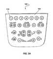
- FIG. 2Ais a front elevational view of the touch panel assembly illustrated in FIG. 1 ;
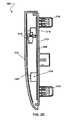
- FIG. 2Bis a rear elevational view of the touch panel assembly illustrated in FIG. 1 ;
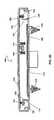
- FIG. 2Cis a side elevational sectional view of the touch panel assembly illustrated in FIG. 1 ;
- FIG. 2Dis a top plan sectional view of the touch panel assembly illustrated in FIG. 1 ;
- FIG. 3is an exploded rear perspective view of the touch panel assembly illustrated in FIG. 1 ;
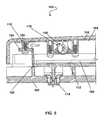
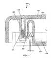
- FIG. 4is a partial sectional view in detail of the touch panel assembly illustrated in FIG. 1 ;
- FIG. 5is a partial sectional view in detail of the touch panel assembly illustrated in FIG. 1 ;
- FIG. 6is a partial sectional view in detail of the touch panel assembly illustrated in FIG. 1 ;
- FIG. 7is a partial sectional view in detail of a flex arm of a touch panel assembly according to another exemplary embodiment of the invention.
- FIG. 8is a partial sectional view in detail of a bezel and a rear cover of a touch panel assembly according to yet another exemplary embodiment of the invention.
- FIG. 9is a plan view of an actuator of a touch panel assembly according to a further embodiment of the invention.
- FIG. 10is a partial sectional view in detail of the touch panel assembly according to a further embodiment of the invention.
- FIG. 11is another partial sectional view in detail of the touch panel assembly illustrated in FIG. 10 .
- the inventionprovides a touch panel assembly 100 with haptic effects and a method of manufacturing the touch panel assembly 100 with haptic effects.
- the touch panel assembly 100provides haptic feedback when the user manipulates an input device 116 .
- the touch panel assembly 100according to one preferred embodiment is shown.
- the touch panel assembly 100can be installed into the dashboard of an automobile, however the invention is not limited to only touch panel assemblies 100 of an automobile.
- the inventionis applicable to touch panel assemblies 100 for other applications.
- an exemplary embodiment where the touch panel assembly 100 is used in an automobileis described.
- the touch panel assembly 100includes, at least, a bezel 102 , a sensor circuit board 104 , an interface circuit board 106 , a retainer bracket 108 , a haptic effect generator 110 , a rear cover 112 , and one or more mountings 114 ,
- Terms such as “front,” “forward,” “back,” “rear,” “to the right,” “to the left,” and other similar termsare not intended to limit the invention. Instead, such terms are used to facilitate describing the positions of components relative to other components.
- the bezel 102 , the sensor circuit board 104 , the interface circuit board 106 , and the rear cover 112are disposed in layers with the bezel 102 and the rear cover 112 substantially encasing the sensor circuit board 104 , the interface circuit board 106 , the retainer bracket 108 , and the haptic effect generator 110 to form the touch panel assembly 100 .
- the bezel 102provides a surface that a user interacts with to provide an input to the touch panel assembly 100 .
- the bezel 102can include at least one input device 116 .
- the input device 116can be pressure sensitive through resistive sensors, electrically sensitive through capacitive sensors, acoustically sensitive through surface acoustic wave sensors, photo sensitive through infrared sensors, and the like. In the embodiment shown, the input device 116 can be depressed by the user. In other embodiments, the input device 116 can be a switch, rotary knob, pull switch, or some other input device that can be implemented with the touch panel assembly 100 .
- the bezel 102can be marked with words, letters, numbers, figures, or other indicia to indicate the function of the input device.
- the bezel 102can be made from any suitably rigid material, including, but not limited to, plastics, metals, leathers, glass, wood, combinations of the aforementioned, and other similar materials.
- the choice of materialalso being suitable for the type of input device 116 used with the touch panel assembly 100 .
- plasticsare used because they have the necessary elastic flexibility that can be used with a depressible input device 116 .
- the bezel 102can be replaced with a touch screen, one or more touch switches, one or more touch pads, and other similar devices that can accept an input from a user.
- the touch screen, touch switches, touch pads, and the likecan be made transparent or translucent and placed over a display device that generates graphical images.
- the display devicecan be a liquid crystal display, a plasma display, an electroluminescent display, a light emitting diode display, or some other device for displaying images, such that the user responds to images to provide an input to the touch panel assembly 100 instead of the indicia of a bezel 102 .
- the sensor circuit board 104includes the corresponding and necessary electrical components, electronics, mechanical components, and other devices that interact with the input device 116 to transform the user's input into an electrical, electro-mechanical, or mechanical signal suitable for use by the touch panel assembly 100 .
- the sensor circuit board 104can be made from a suitable material that provides mechanical support and a mounting surface for the electrical components, electronics, mechanical components, and other devices necessary for the input device 116 .
- the sensor circuit board 104 of the depicted embodimentis disposed immediately adjacent to a surface of the bezel 102 opposite the surface with the input devices 116 .
- the sensor circuit board 104is a dielectric substrate with electronics on the substrate to transform the actuating of an input device 116 into an electrical signal.
- the interface circuit board 106is disposed adjacent to and to the rear of the sensor circuit board 104 .
- the interface circuit board 106 and the sensor circuit board 104can be formed as a single circuit board.
- the touch panel assembly 100can include more than one sensor circuit board 104 and more than one interface circuit board 106 .
- the interface circuit board 106includes electrical components, electronics, mechanical components, and other devices that transform or relay the signal received from the sensor circuit board 104 to the controlled device, such as a component of an audio entertainment system or a heating and cooling system. Similar to the sensor circuit board 104 , the interface circuit board 106 can be made from a suitable material that provides mechanical support and a mounting surface for the electrical components, electronics, mechanical components, and other necessary devices.
- the interface circuit board 106 of the depicted embodimentis disposed immediately adjacent to a surface of the rear cover 112 .
- the interface circuit board 106is a dielectric substrate with electronics on the substrate to transform or relay the electric signal from the sensor circuit board 104 to a device to be controlled by the touch panel assembly 100 .
- the rear cover 112provides protection and mechanical support.
- the rear cover 112can be made from any suitable rigid material, such as, but not limited to, plastics, metals, leathers, glass, wood, combinations of the aforementioned, and other similar materials.
- the rear cover 112joins with the bezel 102 to substantially encompass the sensor circuit board 104 , the interface circuit board 106 , the retainer bracket 108 , and the haptic effect generator 110 to form the touch panel assembly 100 .
- the rear cover 112is coupled to the bezel 102 by at least one flex arm assembly 118 .
- the flex arm assembly 118includes, at least, a coupling 120 to couple the bezel 102 to the rear cover 112 and a flexible arm portion 122 .
- the flexible arm portion 122allows the bezel 102 to elastically move relative to the rear cover 112 .
- the flexible arm portion 122elastically bends when the haptic effect generator 110 is actuated.
- the coupling 120is a screw
- the flexible arm portion 122is a portion of the rear cover 112 formed substantially perpendicular to the rear cover 112 .
- the flexible arm portion 122also has a coupling portion 124 extending from it to engage the coupling 120 .
- a signalis sent to the haptic effect generator 110 .
- the signal sent to the haptic effect generator 110causes it to impart a slight movement to the bezel 102 which informs the user that his manipulation of the input device 116 is being processed by the touch panel assembly 100 .
- the movement caused by the haptic effect generator 110is limited by the flexible arm portion 122 of the flex arm assembly 118 , and the flexible arm portion 122 elastically returns the bezel 102 to substantially its original position relative to the rear cover 112 , i.e., the position before the movement caused by the haptic effect generator 110 .
- the rear cover 112has at least one mounting 114 to couple the touch panel assembly 100 to another structure 126 .
- the rear cover 112provides a surface for mountings 114 to install the touch panel assembly 100 into the dashboard 126 of an automobile.
- the mountings 114can be screws, nuts and bolts, rivets, press fittings, and other similar couplings.
- the mountings 114are spring clips.
- the rear cover 112has at least one flex arm assembly 118 that couples to the bezel 102 and at least one mounting 114 that couples the touch panel assembly 100 to another structure, the rear cover 112 can provide a flex arm assembly 118 in a conventional control panel assembly, can be adapted for use with a wide variety of haptic effect generators 110 thus optimizing the balance between cost and performance, and provides a single component transition between the fixed structure 126 , such as the dashboard, and the moving surface, such as the bezel 102 .
- the retainer bracket 108couples the haptic effect generator 110 to the bezel 102 .
- the haptic effect generator 110provides a haptic effect in response to the user manipulating an input device 116 of the bezel 102 .
- the haptic effect generator 110can provide linear motion, circular motion, or non-linear motion. The motion can simulate a response to a push of a mechanical button or other similar mechanical input devices.
- the motion provided by the haptic effect generator 110can be caused by several different methods, such as, but not limited to, electrical, electromechanical, hydraulic, pneumatic, or mechanical.
- the haptic effect generator 110can be active or passive.
- Active actuatorsinclude, for example, linear current control motors, stepper motors, pneumatic/hydraulic active actuators, voice coil actuators, and other similar devices.
- Passive actuatorsinclude, but are not limited to, dissipative passive actuators, linear magnetic particle brakes, linear friction brakes, pneumatic/hydraulic passive actuators, and other similar devices.
- the haptic effect generator 110can be, but not limited to, a solenoid, a linear resonance actuator, an eccentric rotary mass motor, a linear actuator such as the commercially available “Immersion A100,” piezoelectric film, combinations of the aforementioned, or any other device that can produce a haptic effect.
- the haptic effect generator 110is described as providing a linear motion.
- the haptic effect generator 110includes an eccentric rotary mass, while in the embodiment shown in FIGS. 9-11 , the haptic effect generator 410 includes a linear actuator.
- the haptic effect generator 110has an eccentric rotary mass.
- the eccentric rotary mass of the haptic effect generator 110is beginning to rotate clockwise, and the flexible arm portion 122 of the flex arm assembly 118 is shown in its substantially non-flexed state.
- the flexible arm portion 122can flex either to its left or to its right, and thus, the bezel 102 can move to its left or to its right.
- the eccentric rotary masshas rotated further clockwise and is disposed mostly to the left of the haptic effect generator 110 . Because the mass is positioned substantially to the left of the haptic effect generator 110 , the haptic effect generator 110 causes the bezel 102 to move to the left of the figure. However, the flexible arm portion 122 elastically limits the movement of the bezel 102 to the left.
- the eccentric rotary masshas rotated further clockwise and is disposed mostly to the right of the haptic effect generator 110 . Because the mass is positioned substantially to the right of the haptic effect generator 110 , the haptic effect generator 110 causes the bezel 102 to move to the right of the figure. As before, the flexible arm portion 122 elastically limits the movement of the bezel 102 to the right. Further movement of the rotary mass returns it to substantially its original position, and the flexible arm portion 122 substantially returns the bezel 102 to its original position relative to the rear cover 112 .
- a first surfaceis provided.
- the first surfaceis a surface of the bezel 102 .
- a second surfaceis provided, and a flexible arm portion 122 is disposed on the second surface.
- the flexible arm portion 122can include a coupling portion 124 .
- the second surfaceis a surface of the rear cover 112 .
- a couplingcouples the first surface with the second surface via the coupling portion 124 .
- the couplingis a screw that extends through the coupling portion 124 of the rear cover 112 to a screw hole in the bezel 102 .
- a haptic effect generator 110is disposed on one of the surfaces.
- the haptic effect generator 110is attached to the bezel 102 by a retainer bracket 108 .
- the flex arm assembly 218includes a coupling 220 , a flexible arm portion 222 , and a coupling portion 224 .
- the coupling 220 and the coupling portion 224are substantially similar to the coupling 120 and the coupling portion 124 , respectively, of the touch panel assembly 100 .
- a detailed description of the coupling 220 and the coupling portion 222are omitted.
- the flexible arm portion 222includes a loop. The loop allows the geometry of the flexible arm portion 222 to be varied. For example, the length L can be varied.
- Varying the geometry of the flexible arm portion 222generally changes the elastic force F generated by the deflection d of the flexible arm portion 222 .
- kis the spring constant;
- Fis the force;
- dis the deflection of the flexible arm portion 222 ;
- Eis modulus of elasticity of the material used for the flexible arm portion 222 ;
- Lis the length of the flexible arm portion;
- bis the beam width, i.e., the width of a section of the flexible arm portion 222
- hthe beam thickness, i.e., the height of a section of the flexible arm portion 222 .
- the bezel 302includes a first baffle 330
- the rear cover 312includes a second baffle 332 .
- the first baffle 330 , the second baffle 332 , or bothsubstantially prevents debris or fluid intrusion into the touch panel assembly 300 .
- the second baffle 332can provided with a sealed seat 334 to provide further protection against debris and fluid.
- the first baffle 330is placed inward of the second baffle 332 .
- the first baffle 330 and the second baffle 332are disposed substantially along the periphery of the bezel 302 and the rear cover 312 , respectively.
- the haptic effect generator 410includes an integrated electromagnetic linear actuator.
- a description of an electromagnetic linear actuatoris described in U.S. patent application Ser. No. 11/969,071, filed Jan. 3, 2008, entitled “Haptic Actuator Assembly and Method of Manufacturing a Haptic Actuator Assembly” and is incorporated herein in its entirety by reference.
- the haptic effect generator 410has, at least, a coil 440 , a core 442 , and a ferrous body 446 .
- the coil 440is made of an electrically conductive material wrapped around the core 442 .
- the coil 440produces a magnetic field when an electrical current is applied to the coil 440 .
- the core 442is made of a ferrous material or a material that is magnetized in the presence of a magnetic field. When an electrical current is applied to the coil 440 , a magnetic field is developed in the coil 440 , and the magnetic field causes the core 442 to be attracted magnetically to a nearby ferrous body 446 .
- a touch panel assembly 400is shown with the haptic effect generator 410 in different partial sectional views that show the arrangement of the coil 440 , the core 442 , and the ferrous body 446 relative to the bezel 102 and the rear cover 112 .
- the touch panel assembly 400includes a bezel 102 , a sensor circuit board 104 , a rear cover 112 , at least one mounting 114 , and at least one flex arm assembly 118 .
- the touch panel assembly 400is coupled to a structure 126 .
- the haptic effect generator 410is shown in section so that most of the ferrous body 446 and a tip of the core 442 can be seen.
- the coil 440 and the core 442are coupled to the rear cover 112 , and the ferrous body 446 is coupled to the bezel 102 .
- the ferrous body 446is held by supports 448 which are attached to a base 450 , and the base 450 is attached to the bezel 102 by screws 452 .
- FIG. 11the coil 440 and the core 442 are shown in another partial sectional view wherein a portion of the ferrous body 446 and a portion of the core 442 are shown in section.
- the coil 440 and the core 442are coupled to the rear cover 112 .
- the bezel 102moves with the ferrous body 446 , and the bezel 102 moves relative to the rear cover 112 .
- the flex arm assembly 118pulls the ferrous body 446 away from the core 442 , and thus, the bezel 102 returns to substantially its original position before it moved.
- the inventionprovides a touch panel assembly 100 with haptic effects and a method of manufacturing the touch panel assembly 100 with haptic effects.
- At least one haptic effect generator 110 and at least one flexible arm portion 122are coupled to the touch panel assembly 100 so that a slight movement is imparted to the bezel 102 in response to the user manipulating an input device 116 disposed on the bezel 102 .
- the haptic effect generator 110 and the flexible arm portion 122provide a system with haptic feedback at reduced cost, with simpler manufacturing requirements at lower cost, and with reduced premature component failure.
Landscapes
- Engineering & Computer Science (AREA)
- General Engineering & Computer Science (AREA)
- Theoretical Computer Science (AREA)
- Human Computer Interaction (AREA)
- Physics & Mathematics (AREA)
- General Physics & Mathematics (AREA)
- User Interface Of Digital Computer (AREA)
- Position Input By Displaying (AREA)
Abstract
Description
Claims (14)
Priority Applications (5)
| Application Number | Priority Date | Filing Date | Title |
|---|---|---|---|
| US12/408,824US8169306B2 (en) | 2009-03-23 | 2009-03-23 | Touch panel assembly with haptic effects and method of manufacturing thereof |
| PCT/US2010/028344WO2010111289A2 (en) | 2009-03-23 | 2010-03-23 | Touch panel assembly with haptic effects and method of manufacturing thereof |
| US12/730,013US8976012B2 (en) | 2009-03-23 | 2010-03-23 | Touch panel assembly with haptic effects and method of manufacturuing thereof |
| EP15194301.6AEP3021201B1 (en) | 2009-03-23 | 2010-03-23 | Touch panel assembly with haptic effects |
| EP10756728.1AEP2411896B1 (en) | 2009-03-23 | 2010-03-23 | Touch panel assembly with haptic effects |
Applications Claiming Priority (1)
| Application Number | Priority Date | Filing Date | Title |
|---|---|---|---|
| US12/408,824US8169306B2 (en) | 2009-03-23 | 2009-03-23 | Touch panel assembly with haptic effects and method of manufacturing thereof |
Related Child Applications (1)
| Application Number | Title | Priority Date | Filing Date |
|---|---|---|---|
| US12/730,013Continuation-In-PartUS8976012B2 (en) | 2009-03-23 | 2010-03-23 | Touch panel assembly with haptic effects and method of manufacturuing thereof |
Publications (2)
| Publication Number | Publication Date |
|---|---|
| US20100238053A1 US20100238053A1 (en) | 2010-09-23 |
| US8169306B2true US8169306B2 (en) | 2012-05-01 |
Family
ID=42737076
Family Applications (1)
| Application Number | Title | Priority Date | Filing Date |
|---|---|---|---|
| US12/408,824Active - Reinstated2030-01-16US8169306B2 (en) | 2009-03-23 | 2009-03-23 | Touch panel assembly with haptic effects and method of manufacturing thereof |
Country Status (2)
| Country | Link |
|---|---|
| US (1) | US8169306B2 (en) |
| EP (1) | EP3021201B1 (en) |
Cited By (37)
| Publication number | Priority date | Publication date | Assignee | Title |
|---|---|---|---|---|
| US8456438B2 (en) | 2008-01-04 | 2013-06-04 | Tactus Technology, Inc. | User interface system |
| US8547339B2 (en) | 2008-01-04 | 2013-10-01 | Tactus Technology, Inc. | System and methods for raised touch screens |
| US8553005B2 (en) | 2008-01-04 | 2013-10-08 | Tactus Technology, Inc. | User interface system |
| US8570295B2 (en) | 2008-01-04 | 2013-10-29 | Tactus Technology, Inc. | User interface system |
| US8587548B2 (en) | 2009-07-03 | 2013-11-19 | Tactus Technology, Inc. | Method for adjusting the user interface of a device |
| US8587541B2 (en) | 2010-04-19 | 2013-11-19 | Tactus Technology, Inc. | Method for actuating a tactile interface layer |
| US8619035B2 (en) | 2010-02-10 | 2013-12-31 | Tactus Technology, Inc. | Method for assisting user input to a device |
| US8704790B2 (en) | 2010-10-20 | 2014-04-22 | Tactus Technology, Inc. | User interface system |
| US8922503B2 (en) | 2008-01-04 | 2014-12-30 | Tactus Technology, Inc. | User interface system |
| US8922510B2 (en) | 2008-01-04 | 2014-12-30 | Tactus Technology, Inc. | User interface system |
| US8922502B2 (en) | 2008-01-04 | 2014-12-30 | Tactus Technology, Inc. | User interface system |
| US8928621B2 (en) | 2008-01-04 | 2015-01-06 | Tactus Technology, Inc. | User interface system and method |
| US8947383B2 (en) | 2008-01-04 | 2015-02-03 | Tactus Technology, Inc. | User interface system and method |
| US9013417B2 (en) | 2008-01-04 | 2015-04-21 | Tactus Technology, Inc. | User interface system |
| US9052790B2 (en) | 2008-01-04 | 2015-06-09 | Tactus Technology, Inc. | User interface and methods |
| US9063627B2 (en) | 2008-01-04 | 2015-06-23 | Tactus Technology, Inc. | User interface and methods |
| US20150185848A1 (en)* | 2013-12-31 | 2015-07-02 | Immersion Corporation | Friction augmented controls and method to convert buttons of touch control panels to friction augmented controls |
| US9075525B2 (en) | 2008-01-04 | 2015-07-07 | Tactus Technology, Inc. | User interface system |
| US9116617B2 (en) | 2009-07-03 | 2015-08-25 | Tactus Technology, Inc. | User interface enhancement system |
| US9239623B2 (en) | 2010-01-05 | 2016-01-19 | Tactus Technology, Inc. | Dynamic tactile interface |
| US9274612B2 (en) | 2008-01-04 | 2016-03-01 | Tactus Technology, Inc. | User interface system |
| US9280224B2 (en) | 2012-09-24 | 2016-03-08 | Tactus Technology, Inc. | Dynamic tactile interface and methods |
| US9298261B2 (en) | 2008-01-04 | 2016-03-29 | Tactus Technology, Inc. | Method for actuating a tactile interface layer |
| US9367132B2 (en) | 2008-01-04 | 2016-06-14 | Tactus Technology, Inc. | User interface system |
| US9372565B2 (en) | 2008-01-04 | 2016-06-21 | Tactus Technology, Inc. | Dynamic tactile interface |
| US9405417B2 (en) | 2012-09-24 | 2016-08-02 | Tactus Technology, Inc. | Dynamic tactile interface and methods |
| US9423875B2 (en) | 2008-01-04 | 2016-08-23 | Tactus Technology, Inc. | Dynamic tactile interface with exhibiting optical dispersion characteristics |
| US9552065B2 (en) | 2008-01-04 | 2017-01-24 | Tactus Technology, Inc. | Dynamic tactile interface |
| US9557915B2 (en) | 2008-01-04 | 2017-01-31 | Tactus Technology, Inc. | Dynamic tactile interface |
| US9557813B2 (en) | 2013-06-28 | 2017-01-31 | Tactus Technology, Inc. | Method for reducing perceived optical distortion |
| US9588683B2 (en) | 2008-01-04 | 2017-03-07 | Tactus Technology, Inc. | Dynamic tactile interface |
| US9588684B2 (en) | 2009-01-05 | 2017-03-07 | Tactus Technology, Inc. | Tactile interface for a computing device |
| US9612659B2 (en) | 2008-01-04 | 2017-04-04 | Tactus Technology, Inc. | User interface system |
| US9720501B2 (en) | 2008-01-04 | 2017-08-01 | Tactus Technology, Inc. | Dynamic tactile interface |
| US9760172B2 (en) | 2008-01-04 | 2017-09-12 | Tactus Technology, Inc. | Dynamic tactile interface |
| DE102016014979A1 (en) | 2016-12-16 | 2018-06-21 | Trw Automotive Electronics & Components Gmbh | Operating system for a motor vehicle, interior judgment and steering wheel with operating system |
| CN111438499A (en)* | 2020-03-30 | 2020-07-24 | 华南理工大学 | 5G + industrial AR-based assembly method using constraint-free force feedback |
Families Citing this family (23)
| Publication number | Priority date | Publication date | Assignee | Title |
|---|---|---|---|---|
| EP2398004B1 (en)* | 2010-06-11 | 2021-06-02 | BlackBerry Limited | Electronic device and method of providing tactile feedback |
| US8451240B2 (en) | 2010-06-11 | 2013-05-28 | Research In Motion Limited | Electronic device and method of providing tactile feedback |
| DE102011082142A1 (en) | 2011-09-05 | 2013-03-07 | Continental Automotive Gmbh | operating device |
| EP2680438B1 (en) | 2012-06-29 | 2018-10-10 | Dav | Touch control module |
| US9720500B2 (en)* | 2014-11-07 | 2017-08-01 | Faurecia Interior Systems, Inc | Haptic touch panel assembly for a vehicle |
| US9910493B2 (en)* | 2014-11-07 | 2018-03-06 | Faurecia Interior Systems, Inc. | Suspension component for a haptic touch panel assembly |
| DE102015107828B4 (en) | 2015-05-19 | 2018-03-08 | Trw Automotive Electronics & Components Gmbh | switching device |
| DE102015008184B4 (en)* | 2015-06-25 | 2021-02-25 | Audi Ag | Motor vehicle operating device with blind operable touch screen and method for operating an operating device |
| USD814429S1 (en)* | 2016-03-04 | 2018-04-03 | Grohe Ag | Switch |
| USD814430S1 (en)* | 2016-03-04 | 2018-04-03 | Grohe Ag | Switch |
| DE102016013544B4 (en)* | 2016-11-14 | 2023-07-27 | e.solutions GmbH | Input module with actuator-operated operating element |
| DE102017000159A1 (en)* | 2017-01-11 | 2018-07-12 | GM Global Technology Operations LLC (n. d. Ges. d. Staates Delaware) | Operating element for a motor vehicle |
| DE102017113658A1 (en) | 2017-06-21 | 2018-12-27 | Trw Automotive Electronics & Components Gmbh | Motor vehicle operating device |
| US10457146B2 (en)* | 2017-12-06 | 2019-10-29 | Faurecia Interior Systems, Inc. | Vehicle interior panel with thermal feedback |
| DE102018000873B3 (en)* | 2018-02-02 | 2019-03-14 | Audi Ag | Operating device for a motor vehicle |
| DE102018007708B4 (en) | 2018-04-09 | 2023-11-09 | e.solutions GmbH | Display device |
| DE102018007709B4 (en) | 2018-04-09 | 2025-01-02 | e.solutions GmbH | display device |
| DE102018007427B4 (en) | 2018-04-09 | 2024-09-12 | e.solutions GmbH | Display device |
| CN111516617A (en)* | 2019-02-01 | 2020-08-11 | 佛吉亚(中国)投资有限公司 | Touch module for vehicle interior, interior and vehicle comprising same |
| DE202019002153U1 (en) | 2019-05-16 | 2019-07-02 | Kunststoffverarbeitung Hoffmann Gmbh | Vehicle-mounted haptic signaling system |
| WO2021128018A1 (en)* | 2019-12-24 | 2021-07-01 | 瑞声声学科技(深圳)有限公司 | Profiling tactile feedback device and tactile feedback generating method therefor |
| CN114824875B (en)* | 2021-01-18 | 2024-12-17 | 深圳市北鼎科技有限公司 | Power supply base with vibration sensing touch key |
| EP4287512A1 (en)* | 2022-05-30 | 2023-12-06 | CENTITVC - Centro de Nanotecnologia e Materiais Tecnicos, Funcionais e Inteligentes | Switch control board for mounting to a vehicle interior panel, production method |
Citations (17)
| Publication number | Priority date | Publication date | Assignee | Title |
|---|---|---|---|---|
| EP0419145A1 (en) | 1989-09-22 | 1991-03-27 | Psion Plc | Input device |
| US6031524A (en) | 1995-06-07 | 2000-02-29 | Intermec Ip Corp. | Hand-held portable data terminal having removably interchangeable, washable, user-replaceable components with liquid-impervious seal |
| US6111577A (en)* | 1996-04-04 | 2000-08-29 | Massachusetts Institute Of Technology | Method and apparatus for determining forces to be applied to a user through a haptic interface |
| WO2001008132A1 (en) | 1999-07-21 | 2001-02-01 | Tactiva Incorporated | Force feedback computer input and output device with coordinated haptic elements |
| KR200258353Y1 (en) | 2000-01-19 | 2001-12-29 | 임머숀 코퍼레이션 | Haptic feedback for touchpads and other touch controls |
| US20020033795A1 (en) | 2000-01-19 | 2002-03-21 | Shahoian Erik J. | Haptic interface for laptop computers and other portable devices |
| US20050253643A1 (en) | 2002-10-30 | 2005-11-17 | Sony Corporation | Input device and process for manufacturing the same, portable electronic apparatus comprising input device |
| JP2006119849A (en) | 2004-10-20 | 2006-05-11 | Sony Corp | Piezoelectric body support structure, piezoelectric body mounting method, input device with tactile function and electronic instrument |
| JP2006215738A (en) | 2005-02-02 | 2006-08-17 | Sony Corp | Vibration transmitting structure, input device with tactile function and electronic equipment |
| JP2007034954A (en) | 2005-07-29 | 2007-02-08 | Sony Corp | Input/output device and electronic equipment having input/output device |
| US7215329B2 (en) | 2001-10-10 | 2007-05-08 | Smk Corporation | Touch panel input device |
| US7245048B2 (en) | 2004-07-29 | 2007-07-17 | Fujitsu Component Limited | Tactile panel |
| US7253723B2 (en)* | 2003-05-19 | 2007-08-07 | Donnelly Corporation | Mirror assembly |
| US7416561B2 (en)* | 2002-03-15 | 2008-08-26 | Ophtec B.V. | Intraocular lens for implantation in an eye and instrument and methods for insertion of such a lens |
| US20090174672A1 (en) | 2008-01-03 | 2009-07-09 | Schmidt Robert M | Haptic actuator assembly and method of manufacturing a haptic actuator assembly |
| US7567232B2 (en)* | 2001-03-09 | 2009-07-28 | Immersion Corporation | Method of using tactile feedback to deliver silent status information to a user of an electronic device |
| US7834857B2 (en)* | 2005-09-14 | 2010-11-16 | Volkswagen Ag | Input device having a touch panel and haptic feedback |
Family Cites Families (2)
| Publication number | Priority date | Publication date | Assignee | Title |
|---|---|---|---|---|
| FR2851347B1 (en)* | 2003-02-18 | 2005-10-21 | Giat Ind Sa | MACHINE INTERFACE DEVICE WITH TACTILE INFORMATION RETURN FOR TOUCH SLAB |
| EP1560102A3 (en)* | 2004-02-02 | 2007-02-21 | Volkswagen Aktiengesellschaft | Touchscreen with spring-controlled haptic feedback |
- 2009
- 2009-03-23USUS12/408,824patent/US8169306B2/enactiveActive - Reinstated
- 2010
- 2010-03-23EPEP15194301.6Apatent/EP3021201B1/enactiveActive
Patent Citations (20)
| Publication number | Priority date | Publication date | Assignee | Title |
|---|---|---|---|---|
| EP0419145A1 (en) | 1989-09-22 | 1991-03-27 | Psion Plc | Input device |
| US6031524A (en) | 1995-06-07 | 2000-02-29 | Intermec Ip Corp. | Hand-held portable data terminal having removably interchangeable, washable, user-replaceable components with liquid-impervious seal |
| US6111577A (en)* | 1996-04-04 | 2000-08-29 | Massachusetts Institute Of Technology | Method and apparatus for determining forces to be applied to a user through a haptic interface |
| US6429846B2 (en) | 1998-06-23 | 2002-08-06 | Immersion Corporation | Haptic feedback for touchpads and other touch controls |
| US7148875B2 (en) | 1998-06-23 | 2006-12-12 | Immersion Corporation | Haptic feedback for touchpads and other touch controls |
| WO2001008132A1 (en) | 1999-07-21 | 2001-02-01 | Tactiva Incorporated | Force feedback computer input and output device with coordinated haptic elements |
| US20020033795A1 (en) | 2000-01-19 | 2002-03-21 | Shahoian Erik J. | Haptic interface for laptop computers and other portable devices |
| US20080062145A1 (en)* | 2000-01-19 | 2008-03-13 | Immersion Corporation | Haptic interface for touch screen embodiments |
| KR200258353Y1 (en) | 2000-01-19 | 2001-12-29 | 임머숀 코퍼레이션 | Haptic feedback for touchpads and other touch controls |
| US7567232B2 (en)* | 2001-03-09 | 2009-07-28 | Immersion Corporation | Method of using tactile feedback to deliver silent status information to a user of an electronic device |
| US7215329B2 (en) | 2001-10-10 | 2007-05-08 | Smk Corporation | Touch panel input device |
| US7416561B2 (en)* | 2002-03-15 | 2008-08-26 | Ophtec B.V. | Intraocular lens for implantation in an eye and instrument and methods for insertion of such a lens |
| US20050253643A1 (en) | 2002-10-30 | 2005-11-17 | Sony Corporation | Input device and process for manufacturing the same, portable electronic apparatus comprising input device |
| US7253723B2 (en)* | 2003-05-19 | 2007-08-07 | Donnelly Corporation | Mirror assembly |
| US7245048B2 (en) | 2004-07-29 | 2007-07-17 | Fujitsu Component Limited | Tactile panel |
| JP2006119849A (en) | 2004-10-20 | 2006-05-11 | Sony Corp | Piezoelectric body support structure, piezoelectric body mounting method, input device with tactile function and electronic instrument |
| JP2006215738A (en) | 2005-02-02 | 2006-08-17 | Sony Corp | Vibration transmitting structure, input device with tactile function and electronic equipment |
| JP2007034954A (en) | 2005-07-29 | 2007-02-08 | Sony Corp | Input/output device and electronic equipment having input/output device |
| US7834857B2 (en)* | 2005-09-14 | 2010-11-16 | Volkswagen Ag | Input device having a touch panel and haptic feedback |
| US20090174672A1 (en) | 2008-01-03 | 2009-07-09 | Schmidt Robert M | Haptic actuator assembly and method of manufacturing a haptic actuator assembly |
Cited By (55)
| Publication number | Priority date | Publication date | Assignee | Title |
|---|---|---|---|---|
| US9229571B2 (en) | 2008-01-04 | 2016-01-05 | Tactus Technology, Inc. | Method for adjusting the user interface of a device |
| US8922502B2 (en) | 2008-01-04 | 2014-12-30 | Tactus Technology, Inc. | User interface system |
| US8553005B2 (en) | 2008-01-04 | 2013-10-08 | Tactus Technology, Inc. | User interface system |
| US8570295B2 (en) | 2008-01-04 | 2013-10-29 | Tactus Technology, Inc. | User interface system |
| US8717326B2 (en) | 2008-01-04 | 2014-05-06 | Tactus Technology, Inc. | System and methods for raised touch screens |
| US8922503B2 (en) | 2008-01-04 | 2014-12-30 | Tactus Technology, Inc. | User interface system |
| US8922510B2 (en) | 2008-01-04 | 2014-12-30 | Tactus Technology, Inc. | User interface system |
| US9274612B2 (en) | 2008-01-04 | 2016-03-01 | Tactus Technology, Inc. | User interface system |
| US9760172B2 (en) | 2008-01-04 | 2017-09-12 | Tactus Technology, Inc. | Dynamic tactile interface |
| US8928621B2 (en) | 2008-01-04 | 2015-01-06 | Tactus Technology, Inc. | User interface system and method |
| US8947383B2 (en) | 2008-01-04 | 2015-02-03 | Tactus Technology, Inc. | User interface system and method |
| US8970403B2 (en) | 2008-01-04 | 2015-03-03 | Tactus Technology, Inc. | Method for actuating a tactile interface layer |
| US9013417B2 (en) | 2008-01-04 | 2015-04-21 | Tactus Technology, Inc. | User interface system |
| US9019228B2 (en) | 2008-01-04 | 2015-04-28 | Tactus Technology, Inc. | User interface system |
| US9035898B2 (en) | 2008-01-04 | 2015-05-19 | Tactus Technology, Inc. | System and methods for raised touch screens |
| US9052790B2 (en) | 2008-01-04 | 2015-06-09 | Tactus Technology, Inc. | User interface and methods |
| US9063627B2 (en) | 2008-01-04 | 2015-06-23 | Tactus Technology, Inc. | User interface and methods |
| US9720501B2 (en) | 2008-01-04 | 2017-08-01 | Tactus Technology, Inc. | Dynamic tactile interface |
| US9626059B2 (en) | 2008-01-04 | 2017-04-18 | Tactus Technology, Inc. | User interface system |
| US9619030B2 (en) | 2008-01-04 | 2017-04-11 | Tactus Technology, Inc. | User interface system and method |
| US9612659B2 (en) | 2008-01-04 | 2017-04-04 | Tactus Technology, Inc. | User interface system |
| US9588683B2 (en) | 2008-01-04 | 2017-03-07 | Tactus Technology, Inc. | Dynamic tactile interface |
| US9075525B2 (en) | 2008-01-04 | 2015-07-07 | Tactus Technology, Inc. | User interface system |
| US9098141B2 (en) | 2008-01-04 | 2015-08-04 | Tactus Technology, Inc. | User interface system |
| US9557915B2 (en) | 2008-01-04 | 2017-01-31 | Tactus Technology, Inc. | Dynamic tactile interface |
| US9207795B2 (en) | 2008-01-04 | 2015-12-08 | Tactus Technology, Inc. | User interface system |
| US8547339B2 (en) | 2008-01-04 | 2013-10-01 | Tactus Technology, Inc. | System and methods for raised touch screens |
| US9552065B2 (en) | 2008-01-04 | 2017-01-24 | Tactus Technology, Inc. | Dynamic tactile interface |
| US8456438B2 (en) | 2008-01-04 | 2013-06-04 | Tactus Technology, Inc. | User interface system |
| US9524025B2 (en) | 2008-01-04 | 2016-12-20 | Tactus Technology, Inc. | User interface system and method |
| US9298261B2 (en) | 2008-01-04 | 2016-03-29 | Tactus Technology, Inc. | Method for actuating a tactile interface layer |
| US9495055B2 (en) | 2008-01-04 | 2016-11-15 | Tactus Technology, Inc. | User interface and methods |
| US9367132B2 (en) | 2008-01-04 | 2016-06-14 | Tactus Technology, Inc. | User interface system |
| US9372539B2 (en) | 2008-01-04 | 2016-06-21 | Tactus Technology, Inc. | Method for actuating a tactile interface layer |
| US9372565B2 (en) | 2008-01-04 | 2016-06-21 | Tactus Technology, Inc. | Dynamic tactile interface |
| US9477308B2 (en) | 2008-01-04 | 2016-10-25 | Tactus Technology, Inc. | User interface system |
| US9423875B2 (en) | 2008-01-04 | 2016-08-23 | Tactus Technology, Inc. | Dynamic tactile interface with exhibiting optical dispersion characteristics |
| US9430074B2 (en) | 2008-01-04 | 2016-08-30 | Tactus Technology, Inc. | Dynamic tactile interface |
| US9448630B2 (en) | 2008-01-04 | 2016-09-20 | Tactus Technology, Inc. | Method for actuating a tactile interface layer |
| US9588684B2 (en) | 2009-01-05 | 2017-03-07 | Tactus Technology, Inc. | Tactile interface for a computing device |
| US8587548B2 (en) | 2009-07-03 | 2013-11-19 | Tactus Technology, Inc. | Method for adjusting the user interface of a device |
| US9116617B2 (en) | 2009-07-03 | 2015-08-25 | Tactus Technology, Inc. | User interface enhancement system |
| US9298262B2 (en) | 2010-01-05 | 2016-03-29 | Tactus Technology, Inc. | Dynamic tactile interface |
| US9239623B2 (en) | 2010-01-05 | 2016-01-19 | Tactus Technology, Inc. | Dynamic tactile interface |
| US8619035B2 (en) | 2010-02-10 | 2013-12-31 | Tactus Technology, Inc. | Method for assisting user input to a device |
| US8723832B2 (en) | 2010-04-19 | 2014-05-13 | Tactus Technology, Inc. | Method for actuating a tactile interface layer |
| US8587541B2 (en) | 2010-04-19 | 2013-11-19 | Tactus Technology, Inc. | Method for actuating a tactile interface layer |
| US8704790B2 (en) | 2010-10-20 | 2014-04-22 | Tactus Technology, Inc. | User interface system |
| US9405417B2 (en) | 2012-09-24 | 2016-08-02 | Tactus Technology, Inc. | Dynamic tactile interface and methods |
| US9280224B2 (en) | 2012-09-24 | 2016-03-08 | Tactus Technology, Inc. | Dynamic tactile interface and methods |
| US9557813B2 (en) | 2013-06-28 | 2017-01-31 | Tactus Technology, Inc. | Method for reducing perceived optical distortion |
| US20150185848A1 (en)* | 2013-12-31 | 2015-07-02 | Immersion Corporation | Friction augmented controls and method to convert buttons of touch control panels to friction augmented controls |
| DE102016014979A1 (en) | 2016-12-16 | 2018-06-21 | Trw Automotive Electronics & Components Gmbh | Operating system for a motor vehicle, interior judgment and steering wheel with operating system |
| WO2018108398A1 (en) | 2016-12-16 | 2018-06-21 | Trw Automotive Electronics & Components Gmbh | Operating system for a motor vehicle, interior part and steering wheel with an operating system |
| CN111438499A (en)* | 2020-03-30 | 2020-07-24 | 华南理工大学 | 5G + industrial AR-based assembly method using constraint-free force feedback |
Also Published As
| Publication number | Publication date |
|---|---|
| US20100238053A1 (en) | 2010-09-23 |
| EP3021201A1 (en) | 2016-05-18 |
| EP3021201B1 (en) | 2018-10-31 |
Similar Documents
| Publication | Publication Date | Title |
|---|---|---|
| US8169306B2 (en) | Touch panel assembly with haptic effects and method of manufacturing thereof | |
| US8976012B2 (en) | Touch panel assembly with haptic effects and method of manufacturuing thereof | |
| US20090174672A1 (en) | Haptic actuator assembly and method of manufacturing a haptic actuator assembly | |
| CN1180370C (en) | Touch-sensitive display with haptic feedback | |
| US9436341B2 (en) | Haptic feedback devices | |
| US9690412B2 (en) | Touch interface module | |
| US8395587B2 (en) | Haptic response apparatus for an electronic device | |
| US10401961B2 (en) | Method and apparatus for generating haptic effects using actuators | |
| US9891708B2 (en) | Method and apparatus for generating haptic effects using actuators | |
| US8854331B2 (en) | Method and apparatus for providing haptic feedback utilizing multi-actuated waveform phasing | |
| US7825903B2 (en) | Method and apparatus for providing haptic effects to a touch panel | |
| US8436825B2 (en) | Haptic interaction device | |
| CN107850961B (en) | Operation feeling imparting input device | |
| WO2017018055A1 (en) | Vibration-generating device and operation feel-imparting input device using said vibration-generating device | |
| EP2411896B1 (en) | Touch panel assembly with haptic effects | |
| JP7454383B2 (en) | operating device | |
| KR20110029449A (en) | Small actuator device and method | |
| JP6919620B2 (en) | Electronics | |
| WO2017130768A1 (en) | Tactile sensation providing device |
Legal Events
| Date | Code | Title | Description |
|---|---|---|---|
| AS | Assignment | Owner name:METHODE ELECTRONIC, INC., ILLINOIS Free format text:ASSIGNMENT OF ASSIGNORS INTEREST;ASSIGNORS:SCHMIDT, ROBERT MARK;BANTER, CHARLES BRUCE;SIGNING DATES FROM 20090331 TO 20090629;REEL/FRAME:023276/0152 | |
| FEPP | Fee payment procedure | Free format text:PETITION RELATED TO MAINTENANCE FEES GRANTED (ORIGINAL EVENT CODE: PMFG); ENTITY STATUS OF PATENT OWNER: LARGE ENTITY Free format text:PETITION RELATED TO MAINTENANCE FEES FILED (ORIGINAL EVENT CODE: PMFP); ENTITY STATUS OF PATENT OWNER: LARGE ENTITY | |
| REMI | Maintenance fee reminder mailed | ||
| LAPS | Lapse for failure to pay maintenance fees | ||
| REIN | Reinstatement after maintenance fee payment confirmed | ||
| FP | Lapsed due to failure to pay maintenance fee | Effective date:20160501 | |
| PRDP | Patent reinstated due to the acceptance of a late maintenance fee | Effective date:20160823 | |
| FPAY | Fee payment | Year of fee payment:4 | |
| STCF | Information on status: patent grant | Free format text:PATENTED CASE | |
| SULP | Surcharge for late payment | ||
| MAFP | Maintenance fee payment | Free format text:PAYMENT OF MAINTENANCE FEE, 8TH YEAR, LARGE ENTITY (ORIGINAL EVENT CODE: M1552); ENTITY STATUS OF PATENT OWNER: LARGE ENTITY Year of fee payment:8 | |
| MAFP | Maintenance fee payment | Free format text:PAYMENT OF MAINTENANCE FEE, 12TH YEAR, LARGE ENTITY (ORIGINAL EVENT CODE: M1553); ENTITY STATUS OF PATENT OWNER: LARGE ENTITY Year of fee payment:12 | |
| AS | Assignment | Owner name:BANK OF AMERICA, N.A., AS ADMINISTRATIVE AGENT, NORTH CAROLINA Free format text:SECURITY INTEREST;ASSIGNOR:METHODE ELECTRONICS, INC.;REEL/FRAME:068275/0875 Effective date:20240625 |