US8167952B2 - Arthroplastic implant with shield for basilar joint and related methods - Google Patents
Arthroplastic implant with shield for basilar joint and related methodsDownload PDFInfo
- Publication number
- US8167952B2 US8167952B2US12/203,233US20323308AUS8167952B2US 8167952 B2US8167952 B2US 8167952B2US 20323308 AUS20323308 AUS 20323308AUS 8167952 B2US8167952 B2US 8167952B2
- Authority
- US
- United States
- Prior art keywords
- shield
- implant according
- arthroplastic implant
- arthroplastic
- patient
- Prior art date
- Legal status (The legal status is an assumption and is not a legal conclusion. Google has not performed a legal analysis and makes no representation as to the accuracy of the status listed.)
- Active, expires
Links
- 239000007943implantSubstances0.000titleclaimsabstractdescription128
- 238000000034methodMethods0.000titledescription18
- 210000000236metacarpal boneAnatomy0.000claimsabstractdescription50
- 210000003010carpal boneAnatomy0.000claimsdescription6
- 230000002093peripheral effectEffects0.000claimsdescription5
- 210000000988bone and boneAnatomy0.000description19
- 210000001713trapezium boneAnatomy0.000description16
- 210000003813thumbAnatomy0.000description12
- 206010003246arthritisDiseases0.000description11
- 230000033001locomotionEffects0.000description8
- 210000003484anatomyAnatomy0.000description5
- 210000000845cartilageAnatomy0.000description5
- 238000002513implantationMethods0.000description5
- 201000008482osteoarthritisDiseases0.000description5
- 210000003189scaphoid boneAnatomy0.000description5
- 210000001188articular cartilageAnatomy0.000description4
- 238000004519manufacturing processMethods0.000description4
- 210000000266trapezoid boneAnatomy0.000description4
- 210000000707wristAnatomy0.000description4
- 241000826860TrapeziumSpecies0.000description3
- 238000004873anchoringMethods0.000description3
- 238000001356surgical procedureMethods0.000description3
- 238000011282treatmentMethods0.000description3
- 208000037873arthrodesisDiseases0.000description2
- 230000008901benefitEffects0.000description2
- 230000003247decreasing effectEffects0.000description2
- 230000009760functional impairmentEffects0.000description2
- 239000000017hydrogelSubstances0.000description2
- 230000002757inflammatory effectEffects0.000description2
- 229910052751metalInorganic materials0.000description2
- 239000002184metalSubstances0.000description2
- 238000012986modificationMethods0.000description2
- 230000004048modificationEffects0.000description2
- 210000003205muscleAnatomy0.000description2
- 230000036285pathological changeEffects0.000description2
- 230000006641stabilisationEffects0.000description2
- 238000011105stabilizationMethods0.000description2
- 230000000087stabilizing effectEffects0.000description2
- 239000013589supplementSubstances0.000description2
- 239000011800void materialSubstances0.000description2
- 206010003694AtrophyDiseases0.000description1
- 102000008186CollagenHuman genes0.000description1
- 108010035532CollagenProteins0.000description1
- 208000005137Joint instabilityDiseases0.000description1
- 208000032912Local swellingDiseases0.000description1
- 206010033425Pain in extremityDiseases0.000description1
- 239000004698PolyethyleneSubstances0.000description1
- RTAQQCXQSZGOHL-UHFFFAOYSA-NTitaniumChemical compound[Ti]RTAQQCXQSZGOHL-UHFFFAOYSA-N0.000description1
- 206010048873Traumatic arthritisDiseases0.000description1
- 230000004075alterationEffects0.000description1
- 238000011882arthroplastyMethods0.000description1
- 230000037444atrophyEffects0.000description1
- 239000012620biological materialSubstances0.000description1
- 229960000074biopharmaceuticalDrugs0.000description1
- 230000008468bone growthEffects0.000description1
- 239000000919ceramicSubstances0.000description1
- 230000008859changeEffects0.000description1
- 208000035850clinical syndromeDiseases0.000description1
- 229920001436collagenPolymers0.000description1
- 239000003246corticosteroidSubstances0.000description1
- 230000008878couplingEffects0.000description1
- 238000010168coupling processMethods0.000description1
- 238000005859coupling reactionMethods0.000description1
- 239000003989dielectric materialSubstances0.000description1
- 208000037265diseases, disorders, signs and symptomsDiseases0.000description1
- 208000035475disorderDiseases0.000description1
- 239000003814drugSubstances0.000description1
- 229940079593drugDrugs0.000description1
- 230000000694effectsEffects0.000description1
- 210000001145finger jointAnatomy0.000description1
- 239000012530fluidSubstances0.000description1
- 230000004927fusionEffects0.000description1
- 238000002347injectionMethods0.000description1
- 239000007924injectionSubstances0.000description1
- 208000014674injuryDiseases0.000description1
- 210000000281joint capsuleAnatomy0.000description1
- 210000003041ligamentAnatomy0.000description1
- 210000003991lunate boneAnatomy0.000description1
- 230000014759maintenance of locationEffects0.000description1
- 239000000463materialSubstances0.000description1
- 239000011368organic materialSubstances0.000description1
- 230000000399orthopedic effectEffects0.000description1
- 230000001575pathological effectEffects0.000description1
- 230000007170pathologyEffects0.000description1
- -1polyethylenePolymers0.000description1
- 229920000573polyethylenePolymers0.000description1
- 229920000642polymerPolymers0.000description1
- 229920001296polysiloxanePolymers0.000description1
- 229920002451polyvinyl alcoholPolymers0.000description1
- 235000019422polyvinyl alcoholNutrition0.000description1
- 230000001737promoting effectEffects0.000description1
- 239000002296pyrolytic carbonSubstances0.000description1
- 230000000717retained effectEffects0.000description1
- 206010039073rheumatoid arthritisDiseases0.000description1
- 210000004872soft tissueAnatomy0.000description1
- 229910001220stainless steelInorganic materials0.000description1
- 239000010935stainless steelSubstances0.000description1
- 230000008961swellingEffects0.000description1
- 208000011580syndromic diseaseDiseases0.000description1
- 210000002435tendonAnatomy0.000description1
- 239000010936titaniumSubstances0.000description1
- 229910052719titaniumInorganic materials0.000description1
- 230000008736traumatic injuryEffects0.000description1
Images


Classifications
- A—HUMAN NECESSITIES
- A61—MEDICAL OR VETERINARY SCIENCE; HYGIENE
- A61F—FILTERS IMPLANTABLE INTO BLOOD VESSELS; PROSTHESES; DEVICES PROVIDING PATENCY TO, OR PREVENTING COLLAPSING OF, TUBULAR STRUCTURES OF THE BODY, e.g. STENTS; ORTHOPAEDIC, NURSING OR CONTRACEPTIVE DEVICES; FOMENTATION; TREATMENT OR PROTECTION OF EYES OR EARS; BANDAGES, DRESSINGS OR ABSORBENT PADS; FIRST-AID KITS
- A61F2/00—Filters implantable into blood vessels; Prostheses, i.e. artificial substitutes or replacements for parts of the body; Appliances for connecting them with the body; Devices providing patency to, or preventing collapsing of, tubular structures of the body, e.g. stents
- A61F2/02—Prostheses implantable into the body
- A61F2/30—Joints
- A61F2/42—Joints for wrists or ankles; for hands, e.g. fingers; for feet, e.g. toes
- A61F2/4241—Joints for wrists or ankles; for hands, e.g. fingers; for feet, e.g. toes for hands, e.g. fingers
- A—HUMAN NECESSITIES
- A61—MEDICAL OR VETERINARY SCIENCE; HYGIENE
- A61F—FILTERS IMPLANTABLE INTO BLOOD VESSELS; PROSTHESES; DEVICES PROVIDING PATENCY TO, OR PREVENTING COLLAPSING OF, TUBULAR STRUCTURES OF THE BODY, e.g. STENTS; ORTHOPAEDIC, NURSING OR CONTRACEPTIVE DEVICES; FOMENTATION; TREATMENT OR PROTECTION OF EYES OR EARS; BANDAGES, DRESSINGS OR ABSORBENT PADS; FIRST-AID KITS
- A61F2/00—Filters implantable into blood vessels; Prostheses, i.e. artificial substitutes or replacements for parts of the body; Appliances for connecting them with the body; Devices providing patency to, or preventing collapsing of, tubular structures of the body, e.g. stents
- A61F2/02—Prostheses implantable into the body
- A61F2/30—Joints
- A61F2002/30001—Additional features of subject-matter classified in A61F2/28, A61F2/30 and subgroups thereof
- A61F2002/30108—Shapes
- A61F2002/30199—Three-dimensional shapes
- A61F2002/30224—Three-dimensional shapes cylindrical
- A61F2002/30225—Flat cylinders, i.e. discs
- A—HUMAN NECESSITIES
- A61—MEDICAL OR VETERINARY SCIENCE; HYGIENE
- A61F—FILTERS IMPLANTABLE INTO BLOOD VESSELS; PROSTHESES; DEVICES PROVIDING PATENCY TO, OR PREVENTING COLLAPSING OF, TUBULAR STRUCTURES OF THE BODY, e.g. STENTS; ORTHOPAEDIC, NURSING OR CONTRACEPTIVE DEVICES; FOMENTATION; TREATMENT OR PROTECTION OF EYES OR EARS; BANDAGES, DRESSINGS OR ABSORBENT PADS; FIRST-AID KITS
- A61F2/00—Filters implantable into blood vessels; Prostheses, i.e. artificial substitutes or replacements for parts of the body; Appliances for connecting them with the body; Devices providing patency to, or preventing collapsing of, tubular structures of the body, e.g. stents
- A61F2/02—Prostheses implantable into the body
- A61F2/30—Joints
- A61F2/30767—Special external or bone-contacting surface, e.g. coating for improving bone ingrowth
- A61F2/30771—Special external or bone-contacting surface, e.g. coating for improving bone ingrowth applied in original prostheses, e.g. holes or grooves
- A61F2002/30772—Apertures or holes, e.g. of circular cross section
- A—HUMAN NECESSITIES
- A61—MEDICAL OR VETERINARY SCIENCE; HYGIENE
- A61F—FILTERS IMPLANTABLE INTO BLOOD VESSELS; PROSTHESES; DEVICES PROVIDING PATENCY TO, OR PREVENTING COLLAPSING OF, TUBULAR STRUCTURES OF THE BODY, e.g. STENTS; ORTHOPAEDIC, NURSING OR CONTRACEPTIVE DEVICES; FOMENTATION; TREATMENT OR PROTECTION OF EYES OR EARS; BANDAGES, DRESSINGS OR ABSORBENT PADS; FIRST-AID KITS
- A61F2/00—Filters implantable into blood vessels; Prostheses, i.e. artificial substitutes or replacements for parts of the body; Appliances for connecting them with the body; Devices providing patency to, or preventing collapsing of, tubular structures of the body, e.g. stents
- A61F2/02—Prostheses implantable into the body
- A61F2/30—Joints
- A61F2/30767—Special external or bone-contacting surface, e.g. coating for improving bone ingrowth
- A61F2/30771—Special external or bone-contacting surface, e.g. coating for improving bone ingrowth applied in original prostheses, e.g. holes or grooves
- A61F2002/30878—Special external or bone-contacting surface, e.g. coating for improving bone ingrowth applied in original prostheses, e.g. holes or grooves with non-sharp protrusions, for instance contacting the bone for anchoring, e.g. keels, pegs, pins, posts, shanks, stems, struts
- A61F2002/30879—Ribs
- A61F2002/30881—Circumferential ribs, flanges or fins
- A—HUMAN NECESSITIES
- A61—MEDICAL OR VETERINARY SCIENCE; HYGIENE
- A61F—FILTERS IMPLANTABLE INTO BLOOD VESSELS; PROSTHESES; DEVICES PROVIDING PATENCY TO, OR PREVENTING COLLAPSING OF, TUBULAR STRUCTURES OF THE BODY, e.g. STENTS; ORTHOPAEDIC, NURSING OR CONTRACEPTIVE DEVICES; FOMENTATION; TREATMENT OR PROTECTION OF EYES OR EARS; BANDAGES, DRESSINGS OR ABSORBENT PADS; FIRST-AID KITS
- A61F2/00—Filters implantable into blood vessels; Prostheses, i.e. artificial substitutes or replacements for parts of the body; Appliances for connecting them with the body; Devices providing patency to, or preventing collapsing of, tubular structures of the body, e.g. stents
- A61F2/02—Prostheses implantable into the body
- A61F2/30—Joints
- A61F2/42—Joints for wrists or ankles; for hands, e.g. fingers; for feet, e.g. toes
- A61F2/4241—Joints for wrists or ankles; for hands, e.g. fingers; for feet, e.g. toes for hands, e.g. fingers
- A61F2002/4256—Joints for wrists or ankles; for hands, e.g. fingers; for feet, e.g. toes for hands, e.g. fingers for carpo-metacarpal joints, i.e. CMC joints
- A61F2002/4258—Joints for wrists or ankles; for hands, e.g. fingers; for feet, e.g. toes for hands, e.g. fingers for carpo-metacarpal joints, i.e. CMC joints for trapezo-metacarpal joints of thumbs
- A—HUMAN NECESSITIES
- A61—MEDICAL OR VETERINARY SCIENCE; HYGIENE
- A61F—FILTERS IMPLANTABLE INTO BLOOD VESSELS; PROSTHESES; DEVICES PROVIDING PATENCY TO, OR PREVENTING COLLAPSING OF, TUBULAR STRUCTURES OF THE BODY, e.g. STENTS; ORTHOPAEDIC, NURSING OR CONTRACEPTIVE DEVICES; FOMENTATION; TREATMENT OR PROTECTION OF EYES OR EARS; BANDAGES, DRESSINGS OR ABSORBENT PADS; FIRST-AID KITS
- A61F2/00—Filters implantable into blood vessels; Prostheses, i.e. artificial substitutes or replacements for parts of the body; Appliances for connecting them with the body; Devices providing patency to, or preventing collapsing of, tubular structures of the body, e.g. stents
- A61F2/02—Prostheses implantable into the body
- A61F2/30—Joints
- A61F2/42—Joints for wrists or ankles; for hands, e.g. fingers; for feet, e.g. toes
- A61F2/4261—Joints for wrists or ankles; for hands, e.g. fingers; for feet, e.g. toes for wrists
- A61F2002/4271—Carpal bones
- A61F2002/4274—Distal carpal row, i.e. bones adjacent the metacarpal bones
- A61F2002/4276—Trapezium
- A—HUMAN NECESSITIES
- A61—MEDICAL OR VETERINARY SCIENCE; HYGIENE
- A61F—FILTERS IMPLANTABLE INTO BLOOD VESSELS; PROSTHESES; DEVICES PROVIDING PATENCY TO, OR PREVENTING COLLAPSING OF, TUBULAR STRUCTURES OF THE BODY, e.g. STENTS; ORTHOPAEDIC, NURSING OR CONTRACEPTIVE DEVICES; FOMENTATION; TREATMENT OR PROTECTION OF EYES OR EARS; BANDAGES, DRESSINGS OR ABSORBENT PADS; FIRST-AID KITS
- A61F2230/00—Geometry of prostheses classified in groups A61F2/00 - A61F2/26 or A61F2/82 or A61F9/00 or A61F11/00 or subgroups thereof
- A61F2230/0063—Three-dimensional shapes
- A61F2230/0069—Three-dimensional shapes cylindrical
- A—HUMAN NECESSITIES
- A61—MEDICAL OR VETERINARY SCIENCE; HYGIENE
- A61F—FILTERS IMPLANTABLE INTO BLOOD VESSELS; PROSTHESES; DEVICES PROVIDING PATENCY TO, OR PREVENTING COLLAPSING OF, TUBULAR STRUCTURES OF THE BODY, e.g. STENTS; ORTHOPAEDIC, NURSING OR CONTRACEPTIVE DEVICES; FOMENTATION; TREATMENT OR PROTECTION OF EYES OR EARS; BANDAGES, DRESSINGS OR ABSORBENT PADS; FIRST-AID KITS
- A61F2310/00—Prostheses classified in A61F2/28 or A61F2/30 - A61F2/44 being constructed from or coated with a particular material
- A61F2310/00005—The prosthesis being constructed from a particular material
- A61F2310/00011—Metals or alloys
- A61F2310/00017—Iron- or Fe-based alloys, e.g. stainless steel
- A—HUMAN NECESSITIES
- A61—MEDICAL OR VETERINARY SCIENCE; HYGIENE
- A61F—FILTERS IMPLANTABLE INTO BLOOD VESSELS; PROSTHESES; DEVICES PROVIDING PATENCY TO, OR PREVENTING COLLAPSING OF, TUBULAR STRUCTURES OF THE BODY, e.g. STENTS; ORTHOPAEDIC, NURSING OR CONTRACEPTIVE DEVICES; FOMENTATION; TREATMENT OR PROTECTION OF EYES OR EARS; BANDAGES, DRESSINGS OR ABSORBENT PADS; FIRST-AID KITS
- A61F2310/00—Prostheses classified in A61F2/28 or A61F2/30 - A61F2/44 being constructed from or coated with a particular material
- A61F2310/00005—The prosthesis being constructed from a particular material
- A61F2310/00011—Metals or alloys
- A61F2310/00029—Cobalt-based alloys, e.g. Co-Cr alloys or Vitallium
- A—HUMAN NECESSITIES
- A61—MEDICAL OR VETERINARY SCIENCE; HYGIENE
- A61F—FILTERS IMPLANTABLE INTO BLOOD VESSELS; PROSTHESES; DEVICES PROVIDING PATENCY TO, OR PREVENTING COLLAPSING OF, TUBULAR STRUCTURES OF THE BODY, e.g. STENTS; ORTHOPAEDIC, NURSING OR CONTRACEPTIVE DEVICES; FOMENTATION; TREATMENT OR PROTECTION OF EYES OR EARS; BANDAGES, DRESSINGS OR ABSORBENT PADS; FIRST-AID KITS
- A61F2310/00—Prostheses classified in A61F2/28 or A61F2/30 - A61F2/44 being constructed from or coated with a particular material
- A61F2310/00005—The prosthesis being constructed from a particular material
- A61F2310/00161—Carbon; Graphite
- A61F2310/00173—Graphite
- A—HUMAN NECESSITIES
- A61—MEDICAL OR VETERINARY SCIENCE; HYGIENE
- A61F—FILTERS IMPLANTABLE INTO BLOOD VESSELS; PROSTHESES; DEVICES PROVIDING PATENCY TO, OR PREVENTING COLLAPSING OF, TUBULAR STRUCTURES OF THE BODY, e.g. STENTS; ORTHOPAEDIC, NURSING OR CONTRACEPTIVE DEVICES; FOMENTATION; TREATMENT OR PROTECTION OF EYES OR EARS; BANDAGES, DRESSINGS OR ABSORBENT PADS; FIRST-AID KITS
- A61F2310/00—Prostheses classified in A61F2/28 or A61F2/30 - A61F2/44 being constructed from or coated with a particular material
- A61F2310/00005—The prosthesis being constructed from a particular material
- A61F2310/00365—Proteins; Polypeptides; Degradation products thereof
Definitions
- the present inventionrelates to the field of arthroplastic implants, and, more particularly, to arthroplastic implants for treating disorders of the basilar or carpometacarpal (CMC) joint and related methods.
- CMCbasilar or carpometacarpal
- Osteoarthritiswhich is also known as degenerative arthritis or degenerative joint disease, is characterized by a loss of articular cartilage on adjacent bony surfaces resulting in discomfort, loss of motion, and functional impairment.
- inflammatory arthritisfor example, rheumatoid arthritis
- rheumatoid arthritismay result in a loss of cartilage surfaces from both biochemical and mechanical reasons.
- an accelerated loss of cartilagecan result from traumatic injury to bones and joints and promote posttraumatic arthritis.
- the bony surfacesbecome less protected by cartilage, the patient experiences pain, motion limitation, potential joint instability, and eventual functional impairment. Due to a decreased movement resulting from the pain or joint changes, regional muscles may atrophy, and ligaments may become more lax.
- Osteoarthritisis the most common form of arthritis, but inflammatory and post-traumatic arthritis also affect millions of patients.
- CMCcarpometacarpal
- basic joint of the thumbis the development of pathologic changes of the articular cartilage and surrounding bone at a patient's joint involving, but not limited to, the relationship between the thumb metacarpal and the trapezium (one of the carpal or wrist bones).
- the effects of basilar joint arthritismay include, for example, debilitating hand pain, swelling, and decreased strength and range of motion, making it difficult to do simple tasks. Further pathologic involvement of bones local to the trapezium bone is often seen in this syndrome.
- those with the scaphoid and trapezoid bonesmay also manifest similar pathologic changes of the articular cartilage and surrounding bone due to basilar thumb arthritis.
- CMCcarpometacarpal
- basilar joint of the thumbthe ends of the bones are covered by articular cartilage, thereby providing a natural cushion from compressive forces and are lubricated and nourished by joint (synovial) fluid secreted by specialized cells lining the joint capsule.
- jointserotial
- the cartilagedegrades and the relationship between adjacent or opposing bones is no longer protected from compressive and shear forces by the healthy cartilage cover. This results in a series of mechanical and biochemical alterations that result in pain, limited motion, instability, and deformity.
- Treatment options for CMC or basilar thumb arthritisinclude, for example, splints (temporary immobilization of the patient's basilar joint), medication, corticosteroid injections, and surgery.
- Surgical treatmentsare typically of two general forms: motion-eliminating and motion-sparing options.
- the motion-eliminating alternativeincludes an arthrodesis or a fusion of the bones, thus completely sacrificing all motion between two bones through their respective joint surfaces by promoting bone growth across the former articulation.
- Motion-sparing treatmentsmay include, for example, simple removal of diseased bones (with or without accompanying soft tissue stabilization procedures) or removal of diseased bones and subsequent replacement (arthroplasty) of certain bones in the affected joint with biologic and non-biologic implants. More particularly, for CMC or basilar joint arthritis of the thumb, the trapezium bone of the patient's basilar joint may be partially removed (subtotal excision) or totally removed (total excision) to relieve the discomfort and mechanical problems associated with arthritis. The void created by either partial or complete excision of the joint shared by the trapezium and metacarpal bones (or other local carpal bones, as described) can then be left in that state or the resulting void can be filled by biologic or non-biologic material, i.e. an arthroplastic implant.
- biologic or non-biologic materiali.e. an arthroplastic implant.
- the implantincludes a threaded shaft portion for coupling to the first metacarpal bone of the patient's hand, and an articulating portion coupled thereto for replacing the articulating portion of the trapezium bone.
- Potential drawbacks to the disclosed basilar joint implantsmay include, for example, instability of the implant, i.e. the implant may become dislodged. Moreover, the implants may not be mechanically robust and may break down under constant wear and tear within the basilar joint. Moreover, after implantation, the patient may not be provided with the sufficient thumb motion.
- the bases of the first and second metacarpal bonesmay impinge upon one another and cause the patient discomfort.
- the implantation of such an implantmay inadvertently change the length of the patient's thumb, i.e. foreshortening and telescoping of the osteo-articular column.
- CMCbasilar or carpometacarpal
- an arthroplastic implantfor a basilar joint of a hand of the patient.
- the arthroplastic implantmay include a body having a distal surface and a proximal surface opposite therefrom with the distal surface to be positioned adjacent a first metacarpal bone at the basilar joint of the hand of the patient, and a shield extending outwardly from the distal surface of the body to shield adjacent portions of the first metacarpal bone and a second metacarpal bone of the hand of the patient.
- the arthroplastic implantmay prevent impingement of the patient's first and second metacarpal bones.
- the bodymay have a disk shape, and the shield may have an arcuate shape.
- the proximal surface of the bodymay be positioned adjacent a carpal bone.
- the bodymay have rounded over corner portions.
- the bodymay have a sidewall with a peripheral medial recess therein.
- the shieldmay extend between one quarter to three quarters of a distance around a periphery of the body.
- the body and the shieldmay be integrally formed as a monolithic unit.
- the bodymay include at least one fastener-receiving passageway extending therethrough or a plurality thereof having different diameters.
- the distal surfacemay have one of a planar shape, a convex shaper and a concave shape, for example.
- the proximal surfacemay have one of a planar shape, a convex shape, and a concave shape, for example.
- the arthroplastic implantmay further comprise an anchor peg extending outwardly from the body. More particularly, the anchor peg may a tapered shaped. Also, the anchor peg may have a textured surface. The anchor peg may further have a flexible expandable end.
- Another aspectis directed to a method of making an arthroplastic implant for a basilar joint of a hand of a patient.
- the methodmay include forming a body having a distal surface and a proximal surface opposite therefrom with the distal surface to be positioned adjacent a first metacarpal bone at the basilar joint of the hand of the patient, and forming a shield extending outwardly from the distal surface of the body to shield adjacent portions of the first metacarpal bone and a second metacarpal bone of the hand of the patient.
- the methodmay include providing the arthroplastic implant.
- the arthroplastic implantmay include a body having a distal surface and a proximal surface opposite therefrom with the distal surface to be positioned adjacent a first metacarpal bone at the basilar joint of the hand of the patient, and a shield extending outwardly from the distal surface of the body to shield adjacent portions of the first metacarpal bone and a second metacarpal bone of the hand of the patient.
- the methodmay also include implanting the arthroplastic implant into the basilar joint of the hand of the patient.
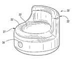
- FIG. 1is a perspective view of an arthroplastic implant according to the invention.
- FIG. 2is a side elevational view of the arthroplastic implant of FIG. 1 .
- FIG. 3is a backside elevational view of the arthroplastic implant of FIG. 1 .
- FIG. 4is a top plan view of the arthroplastic implant of FIG. 1 .
- FIG. 5is a cross-sectional view taken along the lines 5 - 5 of FIG. 3 .
- FIG. 6is a cross-sectional view taken along the lines 6 - 6 of FIG. 2 .
- FIG. 7is a perspective view of another embodiment of the arthroplastic implant according to the invention.
- FIG. 8is a perspective view of yet another embodiment of the arthroplastic implant according to the invention.
- FIG. 9is a top plan view of the arthroplastic implant of FIG. 8 .
- FIG. 10is a side elevational view of the arthroplastic implant of FIG. 8 .
- FIG. 11is a side elevational view of another embodiment of the arthroplastic implant according to the invention.
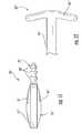
- FIG. 12is a side elevational view of another embodiment of the anchor peg of the arthroplastic implant according to the invention.
- an arthroplastic implant 20 for a basilar or carpometacarpal (CMC) joint of a hand of a patientis now described.
- the arthroplastic implant 20is a motion sparing type implant.
- the arthroplastic implant 20may be used to treat the development of Osteoarthritis, or other forms of joint pathology, in the basilar joint of the patient. Nonetheless, and as will be appreciated by those skilled in the art, the arthroplastic implant 20 may be used to treat other conditions were arthroplastic surgery is desirable, for example, posttraumatic arthritis.
- the arthroplastic implant 20illustratively includes a body 21 having a distal surface 23 and a proximal surface 24 opposite therefrom.
- the distal surface 23is to be positioned adjacent a first metacarpal bone at the basilar joint of the hand of the patient, more particularly, the proximal extent of the first metacarpal bone, and the proximal surface 24 is to be positioned adjacent either the scaphoid bone, the trapezium bone, or a portion thereof, i.e. carpal bones.
- the arthroplastic implant 20may replace (total excision) the trapezium bone of the basilar joint or supplement the trapezium bone (retention or subtotal excision of the trapezium bone) by being interposed between a trapezial remnant (retained trapezium) and the proximal extent of the patient's first metacarpal.
- the body 21illustratively includes a disk shape and has rounded over corner (edge) portions 25 .
- the body 21illustratively includes a sidewall 27 with a peripheral medial recess therein.
- the arthroplastic implant 20illustratively comprises a dielectric material, but may alternatively comprise at least one of the following materials: hydrogel (silicone or polyvinyl alcohols), metal (stainless steel or titanium), biologics (collagen or other organic materials), ceramics (pyrolytic carbon), and polymers (polyethylene), for example.
- the arthroplastic implant 20may comprise a combination of metal and the orthopedic hydrogel.
- the arthroplastic implant 20also includes a shield 22 , which illustratively has an arcuate (convex towards the second metacarpal bone and concave towards the first metacarpal bone) shape, extending outwardly from the distal surface 23 of the body 21 to shield adjacent portions of the first metacarpal bone and a second metacarpal bone of the hand of the patient.
- the shield 22may serve as an interposed “bumper” between the first two rays of the patient's hand, with the convex side of the shield 22 facing the ulnar side of the patient's wrist, and the concave side of the shield 22 facing the radial side of the patient's hand.
- the body 21 and the shield 22may be integrally formed as a monolithic unit, thereby reducing sites of potential mechanical failure, manufacturing costs, and complexity.
- the shield 22may have a near planar shape, i.e. a gentle curvature, since the articular surfaces of the second metacarpal and the trapezoid bones are near flat. Moreover, this gentle curvature of the arthroplastic implant 20 may advantageously cradle the base of the first metacarpal bone. In other embodiments, the radius of curvature of the shield 22 may be greater in order to better accommodate or fit individual anatomic variations in this region of the patient's hand and wrist.
- the arthroplastic implant 20may prevent impingement of the patient's first and second metacarpal bones after implantation, thereby reducing the patient's post surgical implantation discomfort.
- the shield 22also assists in properly positioning the arthroplastic implant 20 in the basilar joint of the patient, i.e. improved stability.
- the thickness of the body 21 of the arthroplastic implant 20may maintain near normal length of osteo-articular column of the thumb, even after complete or partial removal of the trapezium bone, thus preventing foreshortening of the thumb ray.
- the shield 22may extend between one quarter to three quarters of a distance around a periphery of the body 21 . As will be appreciated by those skilled in the art, the length of the shield 22 may vary based upon the native anatomy of the patient.
- the body 21illustratively includes a plurality of fastener-receiving passageways 26 a - 26 c extending therethrough and illustratively being parallel to the distal and proximal surfaces 23 , 24 .
- the fastener-receiving passageways 26 a - 26 cmay receive, for example, a slip of tendon (extensor carpi radialis longus (ECRL) or flexor carpi radialis (FCR) muscles or free graft, for example), sutures of an anchor secured to the base of the second metacarpal bone or the trapezoid bone, or a screw.
- the choice of anchoring of the arthroplastic implant 20may be based upon access available by the native anatomy of the patient and/or the amount of excision for the trapezium bone. Furthermore, some embodiments (not shown) of the arthroplastic implant 20 may not include the fastener-receiving passageways, but may alternatively include another fastener or anchor.
- the distal surface 23illustratively includes a slight concave shape but may alternatively have one or more of a planar shape, a convex shape, or a contoured shape to reflect local anatomy, for example.
- the shape of the distal surface 23may be varied to more accurate fit the base of the first metacarpal bone.
- the proximal surface 24also illustratively includes a concave shape but may alternatively have one or more of a planar shape, a convex shape, or a contoured shape to reflect local anatomy, for example.
- the shape of the proximal surface 24may be varied to more accurate fit either the distal pole of the scaphoid bone (total excision) or the remaining portion of the trapezium bone (subtotal excision).
- the thickness of the body 21 of the arthroplastic implant 20may be variable and permit choices for optimizing the match between the arthroplastic implant and the patient's individual anatomy.
- the arthroplastic implant 20may include a projection or stem of one of several geometric shapes and lengths from this distal surface 23 to be inserted into the medullary canal of the first metacarpal so prepared to accept an implant.
- FIG. 7another embodiment of the arthroplastic implant 20 ′ is now described.
- the arthroplastic implant 20 ′differs from the previous embodiment in that the arthroplastic implant 20 ′ includes only one fastener-receiving passageway 26 ′.
- the body 21 ′does not include a sidewall with a peripheral medial recess.
- an arthroplastic implant 20 for a basilar joint of a hand of a patientmay include forming a body 21 having a distal surface 23 and a proximal surface 24 opposite therefrom with the distal surface to be positioned adjacent a first metacarpal bone at the basilar joint of the hand of the patient, and forming a shield 22 having an arcuate shape, in the illustrated embodiment, and extending outwardly from the distal surface of the body to shield adjacent portions of the first metacarpal bone and a second metacarpal bone of the hand of the patient.
- the methodmay include providing the arthroplastic implant 20 .
- the arthroplastic implant 20may include a body 21 having a distal surface 23 and a proximal surface 24 opposite therefrom with the distal surface to be positioned adjacent a first metacarpal bone at the basilar joint of the hand of the patient, and a shield 22 having an arcuate shape and extending outwardly from the distal surface of the body to shield adjacent portions of the first metacarpal bone and a second metacarpal bone of the hand of the patient.
- the methodmay also include implanting the arthroplastic implant 20 into the basilar joint of the hand of the patient.
- another arthroplastic implant 30 for a basilar joint of a hand of a patientillustratively includes a body 35 having a distal surface 31 and a proximal surface 36 opposite therefrom. After implantation into the basilar joint of the hand of the patient, the distal surface 31 would be positioned adjacent a first metacarpal bone. As with the arthroplastic implant 20 described above, this arthroplastic implant 30 may replace (total excision) the trapezium bone of the basilar joint or supplement the trapezium bone (subtotal excision and non-trapezial excision).
- the arthroplastic implant 30illustratively includes an anchor peg 32 extending outwardly from the body 35 to anchor the body within the basilar joint of the hand of the patient.
- the body 35illustratively includes a disk shape and rounded over corner (edge) portions 34 .
- the arthroplastic implant 30may be accurately implanted into the basilar joint of the patient.
- the anchor peg 32may be coupled to a pre-drilled opening in an adjacent basilar joint bone (proximal first and second metacarpal bone or trapezoid bone) or a screw may be threaded through the anchor peg into the same bones.
- the anchor peg 32illustratively includes a tapered shaped, i.e. the diameter of the anchor peg reduces as it extends from the body 35 .
- the anchor peg 32also illustratively includes a textured surface 33 , for example, the illustrated ribbed surface, a screw (threaded) surface, a smooth surface, a porous surface, or a rough surface.
- the body 35 and the anchor peg 32may be integrally formed as a monolithic unit.
- the arthroplastic implant 30may further comprise a band carrying the anchor peg 32 and positioned to surround the body 35 to thereby join the anchor peg to the body.
- this arthroplastic implant 30illustratively includes convex distal and proximal surfaces 31 , 36 , but the shape of the distal surface 31 may be varied to more accurately fit the base of the first metacarpal bone. Additionally, the shape of the proximal surface 31 may be varied to more accurately fit either the distal pole of the scaphoid bone (total excision) or the remaining portion of the trapezium bone (subtotal or partial excision).
- this arthroplastic implant 30may also include a shield having an arcuate shape and extending outwardly from the distal surface 31 of the body 35 to shield adjacent portions of the first metacarpal bone and a second metacarpal bone of the hand of the patient.
- the arthroplastic implant 20may advantageously further comprise an anchor peg extending outwardly from the body.
- the arthroplastic implants 20 , 30 described hereinmay include one or more of the shield, the anchor peg feature, and the fastener-receiving passageways for greater stabilization.
- FIG. 11another embodiment of the arthroplastic implant 30 ′′ is now described.
- this embodiment of the arthroplastic implant 30 ′′differs from the previous embodiment in that the arthroplastic implant 30 ′′ further comprises a band 41 ′′ carrying the anchor peg 32 ′′ and positioned to surround the body 35 ′′ to thereby join the anchor peg to the body, i.e. the arthroplastic implant 30 ′′ is not monolithic.
- FIG. 12another embodiment of the arthroplastic implant 30 ′′′ is now described.
- this embodiment of the arthroplastic implant 30 ′′′differs from the previous embodiment in that the anchor peg 32 ′′′ illustratively includes a flexible expandable end 40 ′′′.
- the flexible expandable end 40 ′′′ of the anchor peg 32 ′′′has an enlarged size for aiding in anchoring the body 35 ′′′.
- an openingmay be pre-drilled into an adjacent basilar joint bone, and the enlarged flexible expandable end of the anchor peg 32 ′′′ may be compressed to fit through the opening and thereafter expand within the intramedullary portion of the bone, thereby anchoring the arthroplastic implant 30 ′′′.
- an arthroplastic implant 30 for a basilar joint of a hand of a patientmay include forming a body 35 having a distal surface 31 and a proximal surface 36 opposite therefrom with the distal surface to be positioned adjacent a first metacarpal bone at the basilar joint of the hand of the patient, and forming an anchor peg 32 extending outwardly from the body to position the body within the basilar joint of the hand of the patient.
- the methodmay include providing the arthroplastic implant 30 .
- the arthroplastic implant 30may include a body 35 having a distal surface 31 and a proximal surface 36 opposite therefrom with the distal surface to be positioned adjacent a first metacarpal bone at the basilar joint of the hand of the patient, and an anchor peg extending outwardly from the body to position the body within the basilar joint of the hand of the patient.
- the methodmay also include implanting the arthroplastic implant into the basilar joint of the hand of the patient.
Landscapes
- Health & Medical Sciences (AREA)
- Orthopedic Medicine & Surgery (AREA)
- Cardiology (AREA)
- Oral & Maxillofacial Surgery (AREA)
- Transplantation (AREA)
- Engineering & Computer Science (AREA)
- Biomedical Technology (AREA)
- Heart & Thoracic Surgery (AREA)
- Vascular Medicine (AREA)
- Life Sciences & Earth Sciences (AREA)
- Animal Behavior & Ethology (AREA)
- General Health & Medical Sciences (AREA)
- Public Health (AREA)
- Veterinary Medicine (AREA)
- Prostheses (AREA)
Abstract
Description
Claims (32)
Priority Applications (2)
| Application Number | Priority Date | Filing Date | Title |
|---|---|---|---|
| US12/203,259US8343228B2 (en) | 2008-09-03 | 2008-09-03 | Arthroplastic implant with anchor peg for basilar joint and related methods |
| US12/203,233US8167952B2 (en) | 2008-09-03 | 2008-09-03 | Arthroplastic implant with shield for basilar joint and related methods |
Applications Claiming Priority (2)
| Application Number | Priority Date | Filing Date | Title |
|---|---|---|---|
| US12/203,259US8343228B2 (en) | 2008-09-03 | 2008-09-03 | Arthroplastic implant with anchor peg for basilar joint and related methods |
| US12/203,233US8167952B2 (en) | 2008-09-03 | 2008-09-03 | Arthroplastic implant with shield for basilar joint and related methods |
Publications (2)
| Publication Number | Publication Date |
|---|---|
| US20100057213A1 US20100057213A1 (en) | 2010-03-04 |
| US8167952B2true US8167952B2 (en) | 2012-05-01 |
Family
ID=42358655
Family Applications (1)
| Application Number | Title | Priority Date | Filing Date |
|---|---|---|---|
| US12/203,233Active2029-03-10US8167952B2 (en) | 2008-09-03 | 2008-09-03 | Arthroplastic implant with shield for basilar joint and related methods |
Country Status (1)
| Country | Link |
|---|---|
| US (1) | US8167952B2 (en) |
Cited By (6)
| Publication number | Priority date | Publication date | Assignee | Title |
|---|---|---|---|---|
| US20120158153A1 (en)* | 2009-06-23 | 2012-06-21 | Replication Medical Inc. | Trapezium prosthesis |
| CN103815989A (en)* | 2012-11-19 | 2014-05-28 | 苏芳庆 | Artificial implant for carpometacarpal joint |
| US8858644B2 (en) | 2009-01-08 | 2014-10-14 | Memometal Technologies | Orthopaedic implant for arthroplasty of the fingers |
| US9452058B2 (en) | 2012-11-07 | 2016-09-27 | Fong-Chin Su | Artificial implant for carpometacarpal joint |
| US9597192B2 (en) | 2014-06-02 | 2017-03-21 | Stryker European Holdings I, Llc | Metacarpal rod anchor for a trapezometacarpal prosthesis |
| US12427022B1 (en)* | 2024-11-14 | 2025-09-30 | Shoulder Hand Innovations Llc | Systems and methods of thumb caropmetacarpal joints implants |
Families Citing this family (5)
| Publication number | Priority date | Publication date | Assignee | Title |
|---|---|---|---|---|
| EP2427147A1 (en)* | 2009-05-08 | 2012-03-14 | Tornier, Inc. | Joint reconstruction system and method |
| WO2014075114A1 (en)* | 2012-11-09 | 2014-05-15 | Michael Wayne Solomons | Trapezium prosthesis |
| US11642226B2 (en) | 2020-05-01 | 2023-05-09 | Ensemble Orthopedics, Inc. | Implantable interpositional orthopedic pain management |
| US20210338433A1 (en)* | 2020-05-01 | 2021-11-04 | Ensemble Orthopedics, Inc. | Implantable interpositional orthopedic pain management |
| US12290443B2 (en) | 2020-05-01 | 2025-05-06 | Ensemble Orthopedics, Inc. | Implantable interpositional orthopedic pain management |
Citations (40)
| Publication number | Priority date | Publication date | Assignee | Title |
|---|---|---|---|---|
| US4164793A (en) | 1978-04-26 | 1979-08-21 | Swanson Alfred B | Lunate implant |
| US4198712A (en) | 1978-10-13 | 1980-04-22 | Swanson Alfred B | Scaphoid implant |
| US4936860A (en) | 1988-09-23 | 1990-06-26 | Swanson Alfred B | Metal scaphoid implant |
| US4969908A (en) | 1989-06-02 | 1990-11-13 | Swanson Alfred B | Lunate implant and method of stabilizing same |
| US5314485A (en) | 1991-09-12 | 1994-05-24 | Etablissements Tornier | Total prosthesis of the wrist |
| US5326364A (en) | 1992-12-16 | 1994-07-05 | Wright Medical Technology, Inc. | Trapezial implant |
| US5360431A (en) | 1990-04-26 | 1994-11-01 | Cross Medical Products | Transpedicular screw system and method of use |
| WO1996003084A1 (en) | 1994-07-26 | 1996-02-08 | University Of Akron, The | Device and method for restoration of connective tissue |
| US5645605A (en) | 1995-09-18 | 1997-07-08 | Ascension Orthopedics, Inc. | Implant device to replace the carpometacarpal joint of the human thumb |
| US5827285A (en) | 1996-12-12 | 1998-10-27 | Bramlet; Dale G. | Multipiece interfragmentary fixation assembly |
| US5984970A (en) | 1996-03-13 | 1999-11-16 | Bramlet; Dale G. | Arthroplasty joint assembly |
| US5984926A (en) | 1998-02-24 | 1999-11-16 | Jones; A. Alexander M. | Bone screw shimming and bone graft containment system and method |
| US6221074B1 (en) | 1999-06-10 | 2001-04-24 | Orthodyne, Inc. | Femoral intramedullary rod system |
| US6283969B1 (en) | 2000-03-10 | 2001-09-04 | Wright Medical Technology, Inc. | Bone plating system |
| US6302887B1 (en) | 1998-07-20 | 2001-10-16 | Joseph John Spranza | Hardware for high strength fastening of bone |
| US6440135B2 (en) | 2000-02-01 | 2002-08-27 | Hand Innovations, Inc. | Volar fixation system with articulating stabilization pegs |
| US6565960B2 (en) | 2000-06-01 | 2003-05-20 | Shriners Hospital Of Children | Polymer composite compositions |
| US20030216813A1 (en)* | 2002-03-29 | 2003-11-20 | Ball Robert J. | Distal component for wrist prosthesis |
| US6699292B2 (en) | 2000-11-28 | 2004-03-02 | Ascension Orthopedics, Inc. | Interphalangeal joint replacement |
| US20040138754A1 (en) | 2002-10-07 | 2004-07-15 | Imaging Therapeutics, Inc. | Minimally invasive joint implant with 3-Dimensional geometry matching the articular surfaces |
| US20040158251A1 (en) | 1999-04-16 | 2004-08-12 | Morrison Matthew M. | Multi-axial bone anchor system |
| US20050049710A1 (en) | 2003-08-28 | 2005-03-03 | O'driscoll Shawn W. | Prosthesis for partial replacement of an articulating surface on bone |
| US20050070902A1 (en) | 2003-09-30 | 2005-03-31 | Medoff Robert J. | Intramedullary implant for fracture fixation |
| US20050216090A1 (en) | 2004-03-11 | 2005-09-29 | O'driscoll Shawn W | Systems for bone replacement |
| US20050234458A1 (en) | 2004-04-19 | 2005-10-20 | Huebner Randall J | Expanded stabilization of bones |
| US20050245931A1 (en) | 2000-02-01 | 2005-11-03 | Orbay Jorge L | Volar fixation system |
| US20060015101A1 (en) | 2004-07-15 | 2006-01-19 | Wright Medical Technology, Inc. | Intramedullary fixation assembly and devices and methods for installing the same |
| US20060052725A1 (en)* | 2004-09-03 | 2006-03-09 | Santilli Albert N | Small joint orthopedic implants and their manufacture |
| US20060089648A1 (en) | 2004-10-27 | 2006-04-27 | Masini Michael A | Versatile bone plate systems particularly suited to minimally invasive surgical procedures |
| US20060100715A1 (en)* | 2002-09-19 | 2006-05-11 | De Villiers Malan | Arthroplasty implant |
| US20060155284A1 (en) | 2005-01-07 | 2006-07-13 | Depuy Spine Sarl | Occipital plate and guide systems |
| US20060173458A1 (en) | 2004-10-07 | 2006-08-03 | Micah Forstein | Bone fracture fixation system |
| US7090676B2 (en) | 2002-11-19 | 2006-08-15 | Acumed Llc | Adjustable bone plates |
| US20070014649A1 (en) | 2003-04-23 | 2007-01-18 | James Dugal S S | Fixation device and method of fixation |
| US20070043357A1 (en) | 2005-07-29 | 2007-02-22 | X-Spine Systems, Inc. | Capless multiaxial screw and spinal fixation assembly and method |
| US7189237B2 (en) | 2002-11-19 | 2007-03-13 | Acumed Llc | Deformable bone plates |
| US20070083202A1 (en) | 2005-09-20 | 2007-04-12 | Donald Eli Running | Intramedullary bone plate with sheath |
| US20070173834A1 (en) | 2004-04-12 | 2007-07-26 | Thakkar Navin N | Flexible Nail Assembly For Fractures Of Long Bones |
| US20070173841A1 (en) | 2006-01-18 | 2007-07-26 | Ralph James D | Adjustable bone plate |
| US20070265629A1 (en) | 2006-03-07 | 2007-11-15 | Amanda Martin | Distal radius plate |
- 2008
- 2008-09-03USUS12/203,233patent/US8167952B2/enactiveActive
Patent Citations (45)
| Publication number | Priority date | Publication date | Assignee | Title |
|---|---|---|---|---|
| US4164793A (en) | 1978-04-26 | 1979-08-21 | Swanson Alfred B | Lunate implant |
| US4198712A (en) | 1978-10-13 | 1980-04-22 | Swanson Alfred B | Scaphoid implant |
| US4936860A (en) | 1988-09-23 | 1990-06-26 | Swanson Alfred B | Metal scaphoid implant |
| US4969908A (en) | 1989-06-02 | 1990-11-13 | Swanson Alfred B | Lunate implant and method of stabilizing same |
| US5360431A (en) | 1990-04-26 | 1994-11-01 | Cross Medical Products | Transpedicular screw system and method of use |
| US5314485A (en) | 1991-09-12 | 1994-05-24 | Etablissements Tornier | Total prosthesis of the wrist |
| US5326364A (en) | 1992-12-16 | 1994-07-05 | Wright Medical Technology, Inc. | Trapezial implant |
| WO1996003084A1 (en) | 1994-07-26 | 1996-02-08 | University Of Akron, The | Device and method for restoration of connective tissue |
| US5645605A (en) | 1995-09-18 | 1997-07-08 | Ascension Orthopedics, Inc. | Implant device to replace the carpometacarpal joint of the human thumb |
| US5984970A (en) | 1996-03-13 | 1999-11-16 | Bramlet; Dale G. | Arthroplasty joint assembly |
| US6475242B1 (en) | 1996-03-13 | 2002-11-05 | Dale G. Bramlet | Arthroplasty joint assembly |
| US5827285A (en) | 1996-12-12 | 1998-10-27 | Bramlet; Dale G. | Multipiece interfragmentary fixation assembly |
| US5984926A (en) | 1998-02-24 | 1999-11-16 | Jones; A. Alexander M. | Bone screw shimming and bone graft containment system and method |
| WO2001024717A1 (en) | 1998-02-24 | 2001-04-12 | Jones A Alexander M | Bone screw shimming and bone graft containment system and method |
| US6302887B1 (en) | 1998-07-20 | 2001-10-16 | Joseph John Spranza | Hardware for high strength fastening of bone |
| US20040158251A1 (en) | 1999-04-16 | 2004-08-12 | Morrison Matthew M. | Multi-axial bone anchor system |
| US6221074B1 (en) | 1999-06-10 | 2001-04-24 | Orthodyne, Inc. | Femoral intramedullary rod system |
| US20050245931A1 (en) | 2000-02-01 | 2005-11-03 | Orbay Jorge L | Volar fixation system |
| US6440135B2 (en) | 2000-02-01 | 2002-08-27 | Hand Innovations, Inc. | Volar fixation system with articulating stabilization pegs |
| US6283969B1 (en) | 2000-03-10 | 2001-09-04 | Wright Medical Technology, Inc. | Bone plating system |
| US6565960B2 (en) | 2000-06-01 | 2003-05-20 | Shriners Hospital Of Children | Polymer composite compositions |
| US6821530B2 (en) | 2000-06-01 | 2004-11-23 | Shriners Hospitals For Children | Polymer composite compositions |
| US6699292B2 (en) | 2000-11-28 | 2004-03-02 | Ascension Orthopedics, Inc. | Interphalangeal joint replacement |
| US20030216813A1 (en)* | 2002-03-29 | 2003-11-20 | Ball Robert J. | Distal component for wrist prosthesis |
| US20060100715A1 (en)* | 2002-09-19 | 2006-05-11 | De Villiers Malan | Arthroplasty implant |
| US20040138754A1 (en) | 2002-10-07 | 2004-07-15 | Imaging Therapeutics, Inc. | Minimally invasive joint implant with 3-Dimensional geometry matching the articular surfaces |
| US7326212B2 (en) | 2002-11-19 | 2008-02-05 | Acumed Llc | Bone plates with reference marks |
| US7189237B2 (en) | 2002-11-19 | 2007-03-13 | Acumed Llc | Deformable bone plates |
| US7090676B2 (en) | 2002-11-19 | 2006-08-15 | Acumed Llc | Adjustable bone plates |
| US20070014649A1 (en) | 2003-04-23 | 2007-01-18 | James Dugal S S | Fixation device and method of fixation |
| US20050049710A1 (en) | 2003-08-28 | 2005-03-03 | O'driscoll Shawn W. | Prosthesis for partial replacement of an articulating surface on bone |
| US20050070902A1 (en) | 2003-09-30 | 2005-03-31 | Medoff Robert J. | Intramedullary implant for fracture fixation |
| US20050216090A1 (en) | 2004-03-11 | 2005-09-29 | O'driscoll Shawn W | Systems for bone replacement |
| US20070173834A1 (en) | 2004-04-12 | 2007-07-26 | Thakkar Navin N | Flexible Nail Assembly For Fractures Of Long Bones |
| US20050234458A1 (en) | 2004-04-19 | 2005-10-20 | Huebner Randall J | Expanded stabilization of bones |
| US20060015101A1 (en) | 2004-07-15 | 2006-01-19 | Wright Medical Technology, Inc. | Intramedullary fixation assembly and devices and methods for installing the same |
| US20060052725A1 (en)* | 2004-09-03 | 2006-03-09 | Santilli Albert N | Small joint orthopedic implants and their manufacture |
| US20060173458A1 (en) | 2004-10-07 | 2006-08-03 | Micah Forstein | Bone fracture fixation system |
| US20060089648A1 (en) | 2004-10-27 | 2006-04-27 | Masini Michael A | Versatile bone plate systems particularly suited to minimally invasive surgical procedures |
| US20060155284A1 (en) | 2005-01-07 | 2006-07-13 | Depuy Spine Sarl | Occipital plate and guide systems |
| US20070043357A1 (en) | 2005-07-29 | 2007-02-22 | X-Spine Systems, Inc. | Capless multiaxial screw and spinal fixation assembly and method |
| US20070123867A1 (en) | 2005-07-29 | 2007-05-31 | X-Spine Systems, Inc. | Capless multiaxial screw and spinal fixation assembly and method |
| US20070083202A1 (en) | 2005-09-20 | 2007-04-12 | Donald Eli Running | Intramedullary bone plate with sheath |
| US20070173841A1 (en) | 2006-01-18 | 2007-07-26 | Ralph James D | Adjustable bone plate |
| US20070265629A1 (en) | 2006-03-07 | 2007-11-15 | Amanda Martin | Distal radius plate |
Non-Patent Citations (5)
| Title |
|---|
| SBI Small Bone Innovations, SCS (TM) Volar Distal Radius Plate Sytem, Surgical Technique, 2006, pp. 1-9. |
| SBI Small Bone Innovations, SCS ™ Volar Distal Radius Plate Sytem, Surgical Technique, 2006, pp. 1-9. |
| SBI Small Bone Innovations, SCS(TM) Volar Distal Radius Plate, 2008. |
| SBI Small Bone Innovations, SCS™ Volar Distal Radius Plate, 2008. |
| TONIER US, Medical Professionals, Wrist Products, CoverLoc Volar Plate, 2008. |
Cited By (7)
| Publication number | Priority date | Publication date | Assignee | Title |
|---|---|---|---|---|
| US8858644B2 (en) | 2009-01-08 | 2014-10-14 | Memometal Technologies | Orthopaedic implant for arthroplasty of the fingers |
| US20120158153A1 (en)* | 2009-06-23 | 2012-06-21 | Replication Medical Inc. | Trapezium prosthesis |
| US9452058B2 (en) | 2012-11-07 | 2016-09-27 | Fong-Chin Su | Artificial implant for carpometacarpal joint |
| CN103815989A (en)* | 2012-11-19 | 2014-05-28 | 苏芳庆 | Artificial implant for carpometacarpal joint |
| CN103815989B (en)* | 2012-11-19 | 2015-12-23 | 苏芳庆 | Carpometacarpal joint of thumb implant |
| US9597192B2 (en) | 2014-06-02 | 2017-03-21 | Stryker European Holdings I, Llc | Metacarpal rod anchor for a trapezometacarpal prosthesis |
| US12427022B1 (en)* | 2024-11-14 | 2025-09-30 | Shoulder Hand Innovations Llc | Systems and methods of thumb caropmetacarpal joints implants |
Also Published As
| Publication number | Publication date |
|---|---|
| US20100057213A1 (en) | 2010-03-04 |
Similar Documents
| Publication | Publication Date | Title |
|---|---|---|
| US8167952B2 (en) | Arthroplastic implant with shield for basilar joint and related methods | |
| US8343228B2 (en) | Arthroplastic implant with anchor peg for basilar joint and related methods | |
| US11399950B2 (en) | Implant for a bone joint | |
| Sammarco et al. | Complications after surgery of the hallux | |
| US6814757B2 (en) | Joint surface replacement of the distal radioulnar joint | |
| US5458648A (en) | Great toe joint implant and method of implantation | |
| US7037342B2 (en) | Implant for reconstruction of joints | |
| US20120191199A1 (en) | Method and apparatus for distal radioulnar joint (druj) arthroplasty | |
| Adams | Total wrist arthroplasty | |
| AU2002217737A1 (en) | Implant for reconstruction of joints | |
| WO2007109800A2 (en) | Reverse shoulder prosthesis | |
| CN1976652A (en) | Constrained artificial implants for orthopedic use | |
| Anderson et al. | Total wrist arthroplasty | |
| Burton | Basal joint implant arthroplasty in osteoarthritis: indications, techniques, pitfalls, and problems | |
| Taranow et al. | Hallux rigidus: a treatment algorithm | |
| Fadel et al. | Implant arthoplasty of the hallux metatarsophalangeal joint | |
| RU226697U1 (en) | ENDOPROTHESIS OF THE FIRST MATARPHALANGEAL JOINT OF THE FOOT | |
| Adams | Total wrist arthroplasty | |
| Lluch | Osteoarthritis of the Wrist and DRUJ | |
| Adams | Total wrist arthroplasty for rheumatoid arthritis | |
| RU213559U1 (en) | Endoprosthesis of the first metatarsophalangeal joint | |
| CN217593154U (en) | Wrist joint prosthesis | |
| AU2005304745A1 (en) | Metatarsal implant | |
| HOWARD et al. | Silastic condylar arthroplasty | |
| RU202487U1 (en) | ENDOPROTHESIS OF THE FIRST PLUSNOPHALANGAL JOINT OF THE FOOT |
Legal Events
| Date | Code | Title | Description |
|---|---|---|---|
| AS | Assignment | Owner name:MIMEDX, INC.,FLORIDA Free format text:ASSIGNMENT OF ASSIGNORS INTEREST;ASSIGNORS:GRAHAM, THOMAS JAMES, M.D.;BAMBERGER, H. BRENT, DO;CALANDRUCCIO, JAMES HOWARD;AND OTHERS;SIGNING DATES FROM 20080909 TO 20081105;REEL/FRAME:021816/0066 Owner name:MIMEDX, INC., FLORIDA Free format text:ASSIGNMENT OF ASSIGNORS INTEREST;ASSIGNORS:GRAHAM, THOMAS JAMES, M.D.;BAMBERGER, H. BRENT, DO;CALANDRUCCIO, JAMES HOWARD;AND OTHERS;SIGNING DATES FROM 20080909 TO 20081105;REEL/FRAME:021816/0066 | |
| AS | Assignment | Owner name:UPEX HOLDINGS, LLC,WEST VIRGINIA Free format text:ASSIGNMENT OF ASSIGNORS INTEREST;ASSIGNOR:MIMEDX, INC.;REEL/FRAME:023411/0255 Effective date:20091016 Owner name:UPEX HOLDINGS, LLC, WEST VIRGINIA Free format text:ASSIGNMENT OF ASSIGNORS INTEREST;ASSIGNOR:MIMEDX, INC.;REEL/FRAME:023411/0255 Effective date:20091016 | |
| STCF | Information on status: patent grant | Free format text:PATENTED CASE | |
| FPAY | Fee payment | Year of fee payment:4 | |
| MAFP | Maintenance fee payment | Free format text:PAYMENT OF MAINTENANCE FEE, 8TH YR, SMALL ENTITY (ORIGINAL EVENT CODE: M2552); ENTITY STATUS OF PATENT OWNER: SMALL ENTITY Year of fee payment:8 | |
| FEPP | Fee payment procedure | Free format text:11.5 YR SURCHARGE- LATE PMT W/IN 6 MO, SMALL ENTITY (ORIGINAL EVENT CODE: M2556); ENTITY STATUS OF PATENT OWNER: SMALL ENTITY | |
| MAFP | Maintenance fee payment | Free format text:PAYMENT OF MAINTENANCE FEE, 12TH YR, SMALL ENTITY (ORIGINAL EVENT CODE: M2553); ENTITY STATUS OF PATENT OWNER: SMALL ENTITY Year of fee payment:12 |