US8167947B2 - Methods for push distraction and for provision of therapy to adjacent motion segments - Google Patents
Methods for push distraction and for provision of therapy to adjacent motion segmentsDownload PDFInfo
- Publication number
- US8167947B2 US8167947B2US12/821,286US82128610AUS8167947B2US 8167947 B2US8167947 B2US 8167947B2US 82128610 AUS82128610 AUS 82128610AUS 8167947 B2US8167947 B2US 8167947B2
- Authority
- US
- United States
- Prior art keywords
- assembly
- vertebral body
- distal
- rod
- distraction
- Prior art date
- Legal status (The legal status is an assumption and is not a legal conclusion. Google has not performed a legal analysis and makes no representation as to the accuracy of the status listed.)
- Expired - Fee Related, expires
Links
- 230000033001locomotionEffects0.000titleabstractdescription107
- 238000000034methodMethods0.000titleabstractdescription51
- 238000002560therapeutic procedureMethods0.000titleabstractdescription51
- 230000004927fusionEffects0.000abstractdescription47
- 230000006641stabilisationEffects0.000abstractdescription44
- 238000011105stabilizationMethods0.000abstractdescription44
- 238000000605extractionMethods0.000abstractdescription26
- 238000013459approachMethods0.000abstractdescription17
- 239000000463materialSubstances0.000description41
- 238000000429assemblyMethods0.000description29
- 230000000712assemblyEffects0.000description27
- 239000011295pitchSubstances0.000description25
- 208000002193PainDiseases0.000description19
- 230000001225therapeutic effectEffects0.000description18
- 239000007943implantSubstances0.000description17
- 239000012528membraneSubstances0.000description17
- 230000036407painEffects0.000description17
- 238000007726management methodMethods0.000description16
- 210000000988bone and boneAnatomy0.000description15
- 230000006870functionEffects0.000description15
- 230000008901benefitEffects0.000description14
- 238000003780insertionMethods0.000description13
- 230000037431insertionEffects0.000description13
- 238000013461designMethods0.000description10
- 230000014759maintenance of locationEffects0.000description10
- 238000011282treatmentMethods0.000description10
- 210000004705lumbosacral regionAnatomy0.000description9
- 230000008569processEffects0.000description7
- 210000004872soft tissueAnatomy0.000description7
- 210000001519tissueAnatomy0.000description7
- 206010061246Intervertebral disc degenerationDiseases0.000description6
- 230000007850degenerationEffects0.000description6
- 238000004321preservationMethods0.000description6
- 208000037873arthrodesisDiseases0.000description5
- 230000006378damageEffects0.000description5
- 238000002513implantationMethods0.000description5
- 210000005036nerveAnatomy0.000description5
- 238000002360preparation methodMethods0.000description5
- 230000003068static effectEffects0.000description5
- 238000001356surgical procedureMethods0.000description5
- 208000008930Low Back PainDiseases0.000description4
- 238000011882arthroplastyMethods0.000description4
- 230000003416augmentationEffects0.000description4
- 230000006837decompressionEffects0.000description4
- 230000001965increasing effectEffects0.000description4
- 230000002829reductive effectEffects0.000description4
- 230000008439repair processEffects0.000description4
- 238000010079rubber tappingMethods0.000description4
- 239000007787solidSubstances0.000description4
- 210000000278spinal cordAnatomy0.000description4
- 238000004873anchoringMethods0.000description3
- 210000000845cartilageAnatomy0.000description3
- 230000008859changeEffects0.000description3
- 208000018180degenerative disc diseaseDiseases0.000description3
- 238000009826distributionMethods0.000description3
- 238000011065in-situ storageMethods0.000description3
- 238000001802infusionMethods0.000description3
- 238000009434installationMethods0.000description3
- 208000021600intervertebral disc degenerative diseaseDiseases0.000description3
- 230000005012migrationEffects0.000description3
- 238000013508migrationMethods0.000description3
- 230000000278osteoconductive effectEffects0.000description3
- 230000002188osteogenic effectEffects0.000description3
- 230000036961partial effectEffects0.000description3
- 230000035790physiological processes and functionsEffects0.000description3
- 229920001296polysiloxanePolymers0.000description3
- 230000007704transitionEffects0.000description3
- 208000008035Back PainDiseases0.000description2
- 208000000094Chronic PainDiseases0.000description2
- 239000004696Poly ether ether ketoneSubstances0.000description2
- 206010041591Spinal osteoarthritisDiseases0.000description2
- 230000002411adverseEffects0.000description2
- 210000003484anatomyAnatomy0.000description2
- 238000005452bendingMethods0.000description2
- 239000002639bone cementSubstances0.000description2
- 230000008468bone growthEffects0.000description2
- 230000015556catabolic processEffects0.000description2
- 230000006835compressionEffects0.000description2
- 238000007906compressionMethods0.000description2
- 230000001419dependent effectEffects0.000description2
- 201000010099diseaseDiseases0.000description2
- 208000037265diseases, disorders, signs and symptomsDiseases0.000description2
- 238000002224dissectionMethods0.000description2
- 230000009977dual effectEffects0.000description2
- 230000008030eliminationEffects0.000description2
- 238000003379elimination reactionMethods0.000description2
- 230000036541healthEffects0.000description2
- 238000003384imaging methodMethods0.000description2
- 230000001976improved effectEffects0.000description2
- 208000014674injuryDiseases0.000description2
- 230000003993interactionEffects0.000description2
- 210000003205muscleAnatomy0.000description2
- 229920002530polyetherether ketonePolymers0.000description2
- 230000002980postoperative effectEffects0.000description2
- 230000009467reductionEffects0.000description2
- 238000012552reviewMethods0.000description2
- 239000000243solutionSubstances0.000description2
- 208000005801spondylosisDiseases0.000description2
- 230000035882stressEffects0.000description2
- 208000011580syndromic diseaseDiseases0.000description2
- 238000012360testing methodMethods0.000description2
- XLYOFNOQVPJJNP-UHFFFAOYSA-NwaterSubstancesOXLYOFNOQVPJJNP-UHFFFAOYSA-N0.000description2
- 206010002091AnaesthesiaDiseases0.000description1
- 208000010392Bone FracturesDiseases0.000description1
- 206010006811BursitisDiseases0.000description1
- 208000032170Congenital AbnormalitiesDiseases0.000description1
- 208000032767Device breakageDiseases0.000description1
- 208000032766Device expulsionDiseases0.000description1
- 206010017076FractureDiseases0.000description1
- 208000003618Intervertebral Disc DisplacementDiseases0.000description1
- 206010050296Intervertebral disc protrusionDiseases0.000description1
- 208000012659Joint diseaseDiseases0.000description1
- 206010023509KyphosisDiseases0.000description1
- 208000007101Muscle CrampDiseases0.000description1
- 201000002481MyositisDiseases0.000description1
- KHGNFPUMBJSZSM-UHFFFAOYSA-NPerforineNatural productsCOC1=C2CCC(O)C(CCC(C)(C)O)(OC)C2=NC2=C1C=CO2KHGNFPUMBJSZSM-UHFFFAOYSA-N0.000description1
- 208000002607PseudarthrosisDiseases0.000description1
- 208000005392SpasmDiseases0.000description1
- 208000007103SpondylolisthesisDiseases0.000description1
- 229910001069Ti alloyInorganic materials0.000description1
- 229920010741Ultra High Molecular Weight Polyethylene (UHMWPE)Polymers0.000description1
- 208000027418Wounds and injuryDiseases0.000description1
- 230000002159abnormal effectEffects0.000description1
- 239000006096absorbing agentSubstances0.000description1
- 230000009471actionEffects0.000description1
- 230000001154acute effectEffects0.000description1
- 230000032683agingEffects0.000description1
- 230000037005anaesthesiaEffects0.000description1
- 210000001367arteryAnatomy0.000description1
- 230000003190augmentative effectEffects0.000description1
- JUPQTSLXMOCDHR-UHFFFAOYSA-Nbenzene-1,4-diol;bis(4-fluorophenyl)methanoneChemical compoundOC1=CC=C(O)C=C1.C1=CC(F)=CC=C1C(=O)C1=CC=C(F)C=C1JUPQTSLXMOCDHR-UHFFFAOYSA-N0.000description1
- 239000000560biocompatible materialSubstances0.000description1
- 230000015572biosynthetic processEffects0.000description1
- 230000000740bleeding effectEffects0.000description1
- 239000008280bloodSubstances0.000description1
- 210000004369bloodAnatomy0.000description1
- 230000037396body weightEffects0.000description1
- 230000001684chronic effectEffects0.000description1
- 238000004891communicationMethods0.000description1
- 230000001010compromised effectEffects0.000description1
- 230000003247decreasing effectEffects0.000description1
- 238000006731degradation reactionMethods0.000description1
- 230000018044dehydrationEffects0.000description1
- 238000006297dehydration reactionMethods0.000description1
- 230000003111delayed effectEffects0.000description1
- 230000002939deleterious effectEffects0.000description1
- 230000006866deteriorationEffects0.000description1
- 230000001627detrimental effectEffects0.000description1
- 238000005553drillingMethods0.000description1
- 239000003814drugSubstances0.000description1
- 229940079593drugDrugs0.000description1
- 230000000694effectsEffects0.000description1
- 238000005516engineering processMethods0.000description1
- 230000001747exhibiting effectEffects0.000description1
- 230000001815facial effectEffects0.000description1
- 238000011049fillingMethods0.000description1
- 230000010006flightEffects0.000description1
- 239000012530fluidSubstances0.000description1
- 238000002594fluoroscopyMethods0.000description1
- 238000007499fusion processingMethods0.000description1
- 238000007429general methodMethods0.000description1
- 230000003100immobilizing effectEffects0.000description1
- 230000001939inductive effectEffects0.000description1
- 208000015181infectious diseaseDiseases0.000description1
- 230000004054inflammatory processEffects0.000description1
- 238000002347injectionMethods0.000description1
- 239000007924injectionSubstances0.000description1
- 230000001788irregularEffects0.000description1
- 238000005304joiningMethods0.000description1
- 238000002684laminectomyMethods0.000description1
- 210000003041ligamentAnatomy0.000description1
- 230000000670limiting effectEffects0.000description1
- 230000007774longtermEffects0.000description1
- 238000003754machiningMethods0.000description1
- 238000002595magnetic resonance imagingMethods0.000description1
- 238000012423maintenanceMethods0.000description1
- 238000004519manufacturing processMethods0.000description1
- 238000002483medicationMethods0.000description1
- 229910052751metalInorganic materials0.000description1
- 239000002184metalSubstances0.000description1
- 230000004048modificationEffects0.000description1
- 238000012986modificationMethods0.000description1
- 230000003387muscularEffects0.000description1
- 230000001537neural effectEffects0.000description1
- 208000015122neurodegenerative diseaseDiseases0.000description1
- 230000000926neurological effectEffects0.000description1
- 230000000399orthopedic effectEffects0.000description1
- 230000011164ossificationEffects0.000description1
- 230000002138osteoinductive effectEffects0.000description1
- 230000001575pathological effectEffects0.000description1
- 230000037361pathwayEffects0.000description1
- 229930192851perforinNatural products0.000description1
- 230000002085persistent effectEffects0.000description1
- 230000001766physiological effectEffects0.000description1
- 238000004393prognosisMethods0.000description1
- 230000001737promoting effectEffects0.000description1
- 210000000664rectumAnatomy0.000description1
- 230000000717retained effectEffects0.000description1
- 238000007789sealingMethods0.000description1
- 230000035807sensationEffects0.000description1
- 238000000926separation methodMethods0.000description1
- 230000035939shockEffects0.000description1
- 208000005198spinal stenosisDiseases0.000description1
- 210000000115thoracic cavityAnatomy0.000description1
- 230000000451tissue damageEffects0.000description1
- 231100000827tissue damageToxicity0.000description1
- 238000013519translationMethods0.000description1
- 230000008733traumaEffects0.000description1
- 210000003462veinAnatomy0.000description1
- 210000002517zygapophyseal jointAnatomy0.000description1
Images


Classifications
- A—HUMAN NECESSITIES
- A61—MEDICAL OR VETERINARY SCIENCE; HYGIENE
- A61B—DIAGNOSIS; SURGERY; IDENTIFICATION
- A61B17/00—Surgical instruments, devices or methods
- A61B17/56—Surgical instruments or methods for treatment of bones or joints; Devices specially adapted therefor
- A61B17/58—Surgical instruments or methods for treatment of bones or joints; Devices specially adapted therefor for osteosynthesis, e.g. bone plates, screws or setting implements
- A61B17/88—Osteosynthesis instruments; Methods or means for implanting or extracting internal or external fixation devices
- A61B17/8875—Screwdrivers, spanners or wrenches
- A—HUMAN NECESSITIES
- A61—MEDICAL OR VETERINARY SCIENCE; HYGIENE
- A61B—DIAGNOSIS; SURGERY; IDENTIFICATION
- A61B17/00—Surgical instruments, devices or methods
- A61B17/56—Surgical instruments or methods for treatment of bones or joints; Devices specially adapted therefor
- A61B17/58—Surgical instruments or methods for treatment of bones or joints; Devices specially adapted therefor for osteosynthesis, e.g. bone plates, screws or setting implements
- A61B17/68—Internal fixation devices, including fasteners and spinal fixators, even if a part thereof projects from the skin
- A61B17/70—Spinal positioners or stabilisers, e.g. stabilisers comprising fluid filler in an implant
- A—HUMAN NECESSITIES
- A61—MEDICAL OR VETERINARY SCIENCE; HYGIENE
- A61B—DIAGNOSIS; SURGERY; IDENTIFICATION
- A61B17/00—Surgical instruments, devices or methods
- A61B17/56—Surgical instruments or methods for treatment of bones or joints; Devices specially adapted therefor
- A61B17/58—Surgical instruments or methods for treatment of bones or joints; Devices specially adapted therefor for osteosynthesis, e.g. bone plates, screws or setting implements
- A61B17/68—Internal fixation devices, including fasteners and spinal fixators, even if a part thereof projects from the skin
- A61B17/84—Fasteners therefor or fasteners being internal fixation devices
- A61B17/86—Pins or screws or threaded wires; nuts therefor
- A61B17/8645—Headless screws, e.g. ligament interference screws
- A—HUMAN NECESSITIES
- A61—MEDICAL OR VETERINARY SCIENCE; HYGIENE
- A61B—DIAGNOSIS; SURGERY; IDENTIFICATION
- A61B17/00—Surgical instruments, devices or methods
- A61B17/02—Surgical instruments, devices or methods for holding wounds open, e.g. retractors; Tractors
- A61B17/025—Joint distractors
- A61B2017/0256—Joint distractors for the spine
Definitions
- the present disclosurerelates generally to implantable device assemblies, instrumentation systems, and methods for accessing and achieving axial stabilization at multiple levels of the spine via a minimally-invasive trans-sacral approach (as described in U.S. Pat. No. 6,558,390 which is incorporated herein by reference) and subsequent therapeutic procedures, such as spinal arthroplasty; partial or total disc replacement; annulus repair, vertebroplasty; arthrodesis (fusion), or other spine-related procedures comprising the deployment of distal and proximal elongated implantable components and assemblies that can be used to position, manage motion, and stabilize a plurality of adjacent vertebral motion segments in the human spine to relieve lower back pain, restore physiological function of the lumbar spine, to maintain and possibly improve disc health, and prevent progression or transition of degenerative disease.
- a minimally-invasive trans-sacral approachas described in U.S. Pat. No. 6,558,390 which is incorporated herein by reference
- subsequent therapeutic proceduressuch as spinal arthroplasty; partial or total disc
- the present disclosuregenerally relates to the imposition of a sequence of two or more distractions on a set of two or more adjacent motion segments as part of the provision of therapy to the spine.
- the present disclosureincludes methods of distracting a second, more caudal intervertebral disc space after placement of a therapeutic device for distraction and/or therapy of, or in, an adjacent distal motion segment. While the concept of distraction can be applied for moving one item apart from another in any dimension, in the context of this application and the claims that follow, distraction is considered in the orientation of the axes of the spinal column so that distraction elevates the height of, i.e., increases the distance between two adjacent vertebral bodies as measured in the direction of the longitudinal axis of the spine.
- the present disclosureis an extension of work assigned to TranS1 Inc. with a principle place of business located in Wilmington, N.C. Much of the work is described in great detail in the many applications referenced above and incorporated by reference into this application. Accordingly, the background of the disclosure provided herein does not repeat all of the detail provided in the earlier applications, but instead highlights how the present disclosure adds to this body of work.
- the spinal columnis a complex system of bone segments (vertebral bodies and other bone segments) which are in most cases separated from one another by discs in the intervertebral spaces.
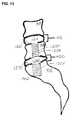
- FIG. 1shows the various segments of a human spinal column as viewed from the side. Each pair of adjacent vertebral bodies and the intervertebral space contributes to the overall flexibility of the spine (known as a motion segment) and contributes to the overall ability of the spine to flex to provide support for the movement of the trunk and head.
- the vertebrae of the spinal cordare conventionally subdivided into several sections. Moving from the head to the tailbone, the sections are cervical 104 , thoracic 108 , lumbar 112 , sacral 116 , and coccygeal 120 .
- the individual segments within the sectionsare identified by number starting at the vertebral body closest to the head.
- the vertebral bodies in the lumbar section and the sacral sectionare usually fused together in adults, it is sufficient and perhaps more descriptive to merely refer to the sacrum rather than the individual sacral components.
- the individual motion segments within the spinal columnsallow movement within constrained limits and provide protection for the spinal cord.
- the discsare important to allow the spinal column to be flexible and to bear the large forces that pass through the spinal column as a person walks, bends, lifts, or otherwise moves.
- the reasons for disc problemsrange from a congenital defect, disease, injury, or degeneration attributable to aging. Often when the discs are not operating properly, the gap between adjacent vertebral bodies is reduced and this causes additional problems including pain.
- a range of therapieshave been developed to alleviate the pain associated with disc problems.
- One class of solutionsis to remove the failed disc and then fuse the two adjacent vertebral bodies together with a permanent but inflexible spacing, also referred to as static stabilization. Fusing one section together ends the ability to flex in that motion segment.
- static stabilizationalso referred to as static stabilization.
- Fusing one section togetherends the ability to flex in that motion segment.
- each motion segmentonly contributes a small portion of the overall flexibility of the spine, it can be a reasonable trade-off to give up the flexibility of a motion segment in an effort to alleviate significant back pain.
- Another class of therapiesattempts to repair the disc so that it resumes operation with the intended intervertebral spacing and mechanical properties.
- One type of repairis the replacement of the original damaged disc with a prosthetic disc. This type of therapy is called by different names such as dynamic stabilization or spinal mobility preservation.
- one of the first steps in providing either type of therapyis to move adjacent vertebral bodies relative to one another (called distraction) to compensate for the reduction of intervertebral space attributed to the problems with the disc.
- distractiona region of intervertebral space attributed to the problems with the disc.
- anteriorrefers to in front of the spinal column; (ventral) and posterior refers to behind the column (dorsal); cephalad means towards the patient's head (sometimes “superior”); caudal (sometimes “inferior”) refers to the direction or location that is closer to the feet.
- proximal and distalare defined in context of this channel of approach. Consequently, proximal is closer to the beginning of the channel and thus towards the feet or the surgeon, distal is further from the beginning of the channel and thus towards the head, or more distant from the surgeon.
- Persistent lower back painis generally “discogenic” in origin, i.e., attributed primarily to herniation and/or degeneration of the disc located between the L5-sacrum and/or the L4-L5 vertebral bodies in the lower lumbar section of the spine (See element 112 in FIG. 1 ).
- Degeneration of the discoccurs when the intervertebral disc of the spine suffers reduced mechanical functionality due to dehydration of the nucleus pulposus.
- the nucleus pulposusprovides for cushioning and dampening of compressive forces to the spinal column.
- the nucleus pulposuscomprises 80% water. With age, the water and protein content of this tissue and the body's cartilage changes resulting in thinner, more fragile cartilage.
- the spinal discs and the facet joints that stack the vertebrae, both of which are partly composed of cartilageare subject to similar degradation over time.
- the gradual deterioration of the disc between the vertebraeis known as degenerative disc disease, or spondylosis. Spondylosis is depicted on x-ray tests or MRI scanning of the spine as a narrowing (height reduction) of the normal “disc space” between adjacent vertebrae.
- the pain from degenerative disc or joint disease of the spinemay be treated conservatively with intermittent heat, rest, rehabilitative exercises, and medications to relieve pain, muscle spasm, and inflammation, but if these treatments are unsuccessful, progressively more active interventions may be indicated.
- therapeutic procedures to alleviate pain and restore functionare described in a progression-of-treatment from spinal arthroplasties, comprising prosthetic nucleus device implantation; annulus repair, and total disc replacement, to spinal arthrodesis, i.e., fusion, with or without concomitant device implantation.
- Fusioninvolves a discectomy, i.e., surgical removal of the disc, followed by the subsequent immobilization of the two vertebral bodies, one superior and one inferior to the excised disc.
- this unit of two vertebral bodies separated axially by a spinal disccomprise a spinal motion segment.
- This procedure of discectomy and “fusion” of the vertebral bodies, i.e., so that the two vertebrae effectively become one solid boneterminates all motion at that joint and is intended to eliminate or at least ameliorate discogenic pain.
- the benefit of fusionis pain relief and the down side is elimination of motion at the fused joint, which can hinder function.
- This surgical optionis generally reserved for patients with advanced disc degeneration, and surgical procedures, such as spinal fusion and discectomy, may alleviate pain, but do not restore normal physiological disc function.
- Typical anterior or posterior surgical approaches and device interventionsgenerally involve lateral screw fixation to the vertebral bodies of the lumbar spine and sacrum and various types of fasteners (rods, plates, etc.) that connect these screws together as one large construct.
- Such approachesalso require muscle and ligament dissection, neural retraction, and annular disruption, i.e., are highly tissue invasive.
- axial spinal mobility preservation devicesor herein, also termed motion management, or “MM” devices
- MM devicesmotion management devices
- the therapeutic advantage of the MM devicesis to preserve mobility by restoring and managing motion via in situ dynamic device performance
- the MM devicesare assemblies that comprise a prosthetic nucleus (PN) component configured as an expandable membrane which is filled in situ, e.g., by injection or infusion of prosthetic nucleus material (PNM) with viscoelastic properties that assist in distraction (i.e., restoring disc height), and share and distribute physiologic loads among the physiologic structures of the vertebral motion segment, including distribution to the annulus and the inferior and superior vertebral bone end plates, so that biomechanical properties and function are optimized.
- PNprosthetic nucleus
- PPMprosthetic nucleus material
- novel axial spinal stabilization systemscomprising device assemblies and deployment instrumentation, that facilitate treatment among a plurality of vertebrae and motion segments at multiple levels of the spine, either by means of fixation or motion management constructs or via a combination of these therapies, which assemblies are introduced via a minimally invasive, pre-sacral access tract and trans-sacral axial surgical approach to the lumbo-sacral spine.
- the axial rods and device assembliesare implanted preferably into the anterior vertebral column by means of device deployment instrumentation to systematically achieve novel means for multi-level axial spinal stabilization via therapeutic intervention or combination of interventions as indicated which selectively target multiple, adjacent motion segments to immobilize vertebral bodes and/or dynamically restore increased range of motion, improve biomechanical function, and provide discogenic pain relief.
- a “motion segment”comprises adjacent vertebrae, i.e., an inferior and a superior vertebral body, and the intervertebral disc space separating said two vertebral bodies, whether enucleated space or with intact or damaged spinal discs.
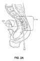
- Axial trans-sacral access to the lumbo-sacral spine as shown in FIG. 2eliminates the need for muscular dissection and other invasive steps associated with traditional spinal surgery while allowing for the design and deployment of new and improved instruments and therapeutic interventions, including stabilization, mobility preservation, and fixation devices/fusion systems across a progression-of-treatment in intervention. More specifically, clinical indications for the multi-level axial spinal stabilization systems and the motion management assemblies described herein include patients requiring interventions to treat pseudoarthrosis, revisions of previous interventions, spinal stenosis, spondylolisthesis (Grade 1 or 2), or degenerative disc disease as defined as back pain of discogenic origin with degeneration of the disc confirmed by history and radiographic studies.
- FIG. 2provides an introductory overview of the process with FIGS. 2A and 2B showing the process of “walking” a blunt tip stylet 204 up the anterior face of the sacrum 116 to the desired position on the sacrum 116 while monitored on a fluoroscope (not shown). This process moves the rectum 208 out of the way so that a straight path is established for the subsequent steps.
- FIG. 2provides an introductory overview of the process with FIGS. 2A and 2B showing the process of “walking” a blunt tip stylet 204 up the anterior face of the sacrum 116 to the desired position on the sacrum 116 while monitored on a fluoroscope (not shown). This process moves the rectum 208 out of the way so that a straight path is established for the subsequent steps.
- FIG. 2provides an introductory overview of the process with FIGS. 2A and 2B showing the process of “walking” a blunt tip stylet 204 up the anterior face of the sacrum 116 to the desired position on the sacrum 116 while monitored on
- FIG. 2Cillustrates a representative axial trans-sacral channel 212 established through the sacrum 116 , the L5/sacrum intervertebral space, the L5 vertebra 216 , the L4/L5 intervertebral space, and into the L4 vertebra 220 .
- trans-sacral approachto provide spinal therapy is described in and commonly assigned U.S. patent application Ser. No. 10/309,416 which is incorporated by reference into this application.
- a brief overview of this method of accessing the spinal region to receive therapyis useful to provide context for the present disclosure.
- FIG. 2Aa pre-sacral approach through percutaneous anterior track towards sacral target, through which trans-sacral axial bore will be made and the access channel extended distally for subsequent advancement of multi-level axial spinal stabilization assemblies.
- An anterior, pre-sacral, percutaneous tractextends through the pre-sacral space anterior to the sacrum.
- the pre-sacral, percutaneous tractis preferably used to introduce instrumentation to access and prepare the access channel (e.g., by drilling a bore in the distal/cephalad direction through one or more lumbar vertebral bodies and intervening discs).
- Percutaneousin this context simply means through the skin and to the posterior or anterior target point, as in transcutaneous or transdermal, without implying any particular procedure from other medical arts.
- percutaneousis distinct from a surgical access, and the percutaneous opening in the skin is preferably minimized so that it is less than 4 cm across, preferably less than 2 cm, and, in certain applications, less than 1 cm across.
- the percutaneous pathwayis generally axially aligned with the bore extending from the respective anterior or posterior target point through at least one sacral vertebral body and one or more lumbar vertebral body in the cephalad direction as visualized by radiographic or fluoroscopic equipment.
- the lumbar spineis accessed via a small skin puncture adjacent to the tip of the coccyx bone.
- the pre-sacral spaceis entered, using standard percutaneous technique, and the introducer assembly with the stylet's blunt tip serving as a dilator is placed through the paracoccygeal entry site.
- the blunt tipis rotated back against the anterior face of the sacrum and “walked” to the desired position on the sacrum under fluoroscopic guidance.
- the blunt-tipped styletis removed and a guide pin, or wire, is safely introduced through the guide pin introducer tube, and “tapped in”.
- the guide pinestablishes the trajectory for placement of subsequent bone dilators and sheath through which a twist drill is introduced creating an axial bore track, the lumen of which is extended distally.
- the guide pinmaintains the axial alignment of access and preparation tools as well as the alignment of cannulated spinal stabilization devices and assemblies, of larger diameter than the bore track, that are subsequently introduced over a 23′′ long, 0.090′′ diameter guide pin and through an exchange cannula for deployment within the vertebral column, as described at least in part in and commonly assigned U.S. patent application Ser. Nos.
- spinal arthrodesisis used in the context of fixation/fusion, leading to immobilization of two vertebral bodies within a motion segment, relative to one another.
- soft fusionrefers to immobilization by means of the introduction of bone growth facilitation/augmentation materials (e.g., osteogenic; osteoconductive media) without accompanying implantation of fixation devices (e.g., fusion rods).
- spinal arthroplasty and/or motion managementencompass dynamic stabilization options for treating disc degeneration in a progression-of-treatment, i.e., when fusion is deemed too radical an intervention based on an assessment of the patient's age, degree of disc degeneration, and prognosis.
- dynamicrefers to non-static motion management devices inherently configured to allow mobility by enabling or facilitating forces or load bearing that assist or substitute for physiological structures that are otherwise compromised, weakened or absent.
- Mobility devices providing dynamic stabilizationare provided across a progression-of-treatment for treating symptomatic discogenic pain, ranging from treatment in patients where little degeneration or collapse is evident radio-graphically, to those for whom prosthetic nucleus devices or total disc replacements are indicated.
- a prosthetic nucleuswould be indicated in patients with a greater degree of degeneration and loss of disc height but not to the stage where advanced annular break-down is present.
- a PNwould go beyond DS by including an aggressive nucleectomy and subsequent filling of the de-nucleated space with an appropriate material.
- TDRtotal disc replacement
- PDRpartial disc replacement
- therapeutic dynamic stabilization device assemblieswhich provide, by design, resistance and limitation of motion in a controlled manner.
- “resistance”refers to the force required to move through a full range of motion
- “limitation”refers to not force but degree, i.e., curtailment of full range of motion in one or more directions.
- full range of motioncomprises about 12 degrees of flexion, about 8 degrees of extension, about 4 degrees of left or right lateral bend, and about 2 degrees of clockwise or counterclockwise motion at each motion segment.
- Biomechanical properties of the mobility devicesmay be altered by design. For example, a flex coupler embodiment which supports a static load of about 100 lbs.
- mm deflectionmay be modified, by changing (reducing) the number of coils per turn, moving from a spring constant of about 2500 psi, or by altering “waist” diameter, i.e., the cross sectional area of the flexible mid-section of the device, which causes it to be stiffer, to withstand 200 lbs. at 1 mm deflection.
- devicesmay be preferentially configured to comprise, for example, a mechanical stop(s) to limit motion, and/or resistance to motion, e.g., by varying cross-sectional area and hence stiffness, or other biomechanical properties relevant to preserving or restoring physiological function with respect to mobility.
- the assembliesmay be constructed to provide full, unconstrained range of motion, semi-constrained range of motion where full range of motion is allowed in combination with increased resistance to motion, or limited range of motion wherein the extent of motion in one or more degrees of freedom is mechanically limited, with or without increased resistance to motion.
- the spinal devices comprised in the inventive assembliespreferably selectively approximate the biomechanical properties (e.g., substantially matched bulk and compression modulus) of the physiological vertebral or disc structure(s) depending on the particular function(s) for which specific therapeutic procedure(s) are indicated.
- biomechanical propertiese.g., substantially matched bulk and compression modulus
- an axial spinal MM devicecomprises PN augmentation or replacement material, that provides the same load-bearing functions and characteristics as the natural disc nucleus and of the natural disc, said PN material contained within expandable membranes, comprised of elastomeric materials, e.g., silicone.
- elastomeric materialse.g., silicone.
- Exemplary siliconeis such as that obtained from Nusil Silicone Technology located in Carpeneria, Calif., exhibiting elongation of between about 500% and about 1500%, and most preferably at about 1000%, and having a wall thickness of 0.015′′ serve as a primary dynamic stabilization component, via load assimilation and load distribution, when filled and expanded via infusion or inflation with an appropriate material.
- the spinal MM devicemay be configured via engagement means as part of an inter-axial device assembly comprising a plurality of axial MM devices, or as assemblies comprising some combination of axial MM device(s) and axial fixation rod(s).
- thisis achieved by means of axial deployment of devices with an aspect ratio of greater than 1, i.e., the device dimension in the axial vertebral plane is greater than the device dimension in any orthogonal direction to that axial plane in close proximity to the physiological instantaneous center of axial rotation.
- axial rodrefers to axially deployed spinal implants which are fabricated, for example, by machining from metal, cylindrical (i.e., rod-like) solid blanks, and said term may encompass fixation/fusion or motion management devices as indicated, since the specific nature, form and function of such devices are determined by/dependent upon final implant configuration.
- fixation/fusion or motion management devicesas indicated, since the specific nature, form and function of such devices are determined by/dependent upon final implant configuration.
- the fabrication, forms, and function of various implant configurations of axial spinal motion management devices to preserve or restore mobilityare disclosed in and commonly assigned U.S. patent application Ser. Nos. 10/972,184, 10/972,039, 10/972,040, and 10/972,176, all of which were filed on Oct. 22, 2004 the contents of which are hereby incorporated in their entirety into this disclosure by reference.
- the axial rodsserve multiple purposes, including but not limited to, modifying the height between the bodies, assuming physiological axial loads, providing access for the introduction of osteogenic and/or osteoconductive materials, and precluding device expulsion by means of anchoring.
- the method of using the distraction/fusion rodgenerally comprises the steps of: determining the desired change in disc height between targeted vertebral bodies; selecting a rod with the appropriate thread pitches in the distal and proximal sections to achieve the desired change in height; accessing the targeted bodies by creating an axial bore that extends in the distal (cephalad) direction from a target point on the anterior surface of the sacrum to the disc space between the targeted bodies; extending the axial bore in the distal direction to create an extended portion of the axial bore, wherein the extended portion has a smaller diameter than the portion of the axial bore extending from the sacral target point to the disc space between the targeted bodies; and advancing and implanting the selected rod into the targeted bodies to achieve the desired change in disc height.
- devices and assemblieswhen devices and assemblies are anchored in bone to eliminate migration and expulsion they are preferably configured with self-tapping, bone anchoring threads configured to distribute stress evenly over a large surface area.
- the threadsare typically of “cancellous” type bone threads known in the art. More specifically, they are typically but not exclusively cut with generally flat faces on the flights of the thread with the flattest of the faces oriented in the direction of the applied load.
- a setcan be male or female
- a set of threadscan be right handed or left handed.
- the number of threads per unit length (pitch)can be varied from one set of threads to another.
- the minor and major diameters of the threadscan be varied from one set of threads to another.
- form of the threadsthe shape of a cross section of a thread can vary from one set of threads to another (such as V-shaped threads or buttress threads).
- one set of threadsis said to be the same type as another set of threads when all of these parameters are the same such that the another set of threads can be rotated into a thread path cut by the first set of threads without needing to cut a new thread path (if the another set of threads is keyed or timed to place the another set of threads into the proper position to start into the previously cut thread path).
- stop flow meanssuch as an axial rod plug are used to preclude leakage or migration of the prosthetic nucleus material either through an axial spinal dynamic stabilization rod or from the intervertebral disc space.
- assemblymay refer, in context, to a single implant which when fully deployed within the spine comprises at least two distinct parts that are configured and engaged in and referred to as an intra-axial alignment, for example, an axial rod and an axial rod plug internally engaged and axially aligned within (i.e., longitudinally) said axial rod.
- assemblymay refer to the combination of a plurality of single-part implants and/or two part intra-axial devices-assemblies, such as just described above, which are configured with engagement means enabling constructs as inter-axial components that collectively comprise an integrated unit or assembly, for example, a distal component rod or rod-assembly as the distal implant in engagement along the center line of a longitudinal axis and axially aligned with a proximal component rod or rod-assembly, as the proximal implant wherein the two components collectively comprise a two-level axial stabilization assembly for two adjacent motion segments, e.g., L4-L5 (distal) and L5-sacrum (proximal).
- L4-L5distal
- L5-sacrumproximal
- multi-level axial stabilization assembliesare configured from two components: a distal component rod, comprising a threaded distal end with a first thread pitch and a threaded proximal end with a second, different thread pitch (hereinafter referred to as dissimilar thread pitches); and a proximal component rod, comprising a distal end that is a tapered and non-threaded cylinder and a threaded proximal end comprising tapered distal threads; said component rods (with or without accompanying intra-axially engaged rod plugs) which are sequentially deployed by means of instrumentation and methods as will be described below, as fixation implants in adjacent motion segments, e.g., first in L4-L5 (superior/distal component rod) and then L5-sacrum (inferior/proximal component rod), respectively; so that the subsequent engagement of the distal end of the proximal component rod internally within and in inter-axial alignment with the proximal
- Thread pitchis defined as the distance between corresponding points on consecutive threads, i.e., threads per inch or TPI.
- This design using dissimilar thread pitchesallows each end of the rod to screw into the superior and inferior vertebral bodies of the L4-L5 motion segment at independent rates resulting in distraction of the two vertebrae and an increase in disc height without the need for additional “distracting” instrumentation as is required in other arthrodesis.
- the degree or amount of distraction to be achievedmay be selected by pre-determining the variability in thread pitch between the threaded distal and proximal ends.
- the proximal component rodin order to enable adequate and simultaneous distraction and subsequent therapy of a second motion segment (proximal) disc space, the proximal component rod needs only to be threaded at its proximal end as described in the preceding paragraph, so that as its threads engage the proximal vertebral body said component is both anchored and advanced into the proximal disc space until its distal end subsequently engages the distal component rod's proximal end, effectively comprising an integral implant assembly.
- distraction of the proximal disc spaceis thereafter achieved by means of force applied, in the distal direction, to the proximal end of the distal component subsequent to said engagement of the two components, so that the distal end of the proximal component will push against and lift the proximal end of the distal component.
- the device assembliesare configured to mechanically and adjustably, distract multiple disc spaces and configured to be deployed so as to be oriented in approximately the line of principal compressive stress, i.e., the device is configured to be placed at approximately the center of rotation in a human disc motion segment. In turn, this yields a more uniform, radial distribution of loads to more closely approximate physiological load sharing.
- the axial stabilization devices disclosed hereinare less likely to cause the phenomena of subsidence and transition syndrome.
- subsidencerefers to the detrimental descent of an orthopedic implant into bone that surrounds it.
- Transition syndromerefers to altered biomechanics and kinematics of contiguous vertebral levels and concomitant risk of adjacent motion segment instability that may occur as a result of spinal therapeutic procedures that are suboptimal in terms of their ability to restore physiological function and properties, and thus risk a cascading deleterious effect on surrounding otherwise healthy tissue.
- yet another advantage of the present disclosureis the concurrent implementation of a combination of therapies, i.e., deployment of spinal assemblies are disclosed that enable dynamic stabilization via implantation of one or more prosthetic nucleus devices or other mobility preservation/restoration devices, such as those disclosed and described previously in and commonly assigned U.S. patent application Ser. Nos. 10/972,184, 10/972,039, 10/972,040, and 10/972,176, all of which were filed on Oct. 22, 2004 incorporated herein in their entirety into this disclosure by reference, as alternative options to or together with fixation rods facilitating fusion of the vertebral bodies, to selectively achieve motion management rather than elimination of motion with respect to a targeted plurality of motion segments within multiple spinal levels.
- MM devicesdecompress the disc and alleviate pain caused by nerve impingement, usually posterior, by means of either inducing slight segmental kyphosis (introduction of added convex curvature through increasing the height on the posterior side of the disc more than on the anterior side of the disc) or straight elevation, and by creating limits and resistance to segmental motion.
- devicesare able to provide both stable anterior and posterior load support (e.g., loads that may approximate 10 times the body weight of a patient) and adequate medial-lateral and rotational support, without adjunctive posterior instrumentation and without accompanying osteogenesis.
- Certain of the dynamic stabilization devices of the present disclosurecomprise a flexible member in between more rigid distal and proximal threaded anchor portions.
- the flexible memberwhich may comprise a cable, spring, flexible coupler, stacked-washers, inflatable bladder (e.g., expandable membrane), or a combination thereof, serves as a “shock absorber”, and is able to assimilate forces or redistribute loads.
- the mobility device assemblycomprising one or more flexible member(s), in combination with at least one anchor portion(s), may be configured from among these design concepts and embodiments, including: helical flexure (flexible coupler) designs, comprising one-piece or two-piece devices that may be configured with or without an integral, elastomeric or elastic inflatable, i.e., expandable, membrane that serves to maximize surface area over which loads are distributed, and that may or may not assist in distraction; cable designs, comprising one piece of fixed length, with or without an inflatable membrane, or two or more parts of variable length; ball and track multi-part designs; “stacked washer” designs, and anchored nuclear replacements.
- helical flexure (flexible coupler) designscomprising one-piece or two-piece devices that may be configured with or without an integral, elastomeric or elastic inflatable, i.e., expandable, membrane that serves to maximize surface area over which loads are distributed, and that may or may not assist in distraction
- cable designscomprising one piece of fixed length, with or without an inflatable
- PND axially deployed in the L5-sacrum lumbar spineenable/accommodate range of motion of between about 10° to 15° flexion; between about 7° to about 10° extension; about 5° of left or right lateral bending and between about 1° to about 2° clockwise or counterclockwise axial rotation
- those implanted in L4-L5enable/accommodate range of motion of between about 8° to 10° flexion; between about 5° to about 7° extension; between about 5° to about 7° left or right lateral bending; and between about 1° to about 4° clockwise or counterclockwise axial rotation.
- the overall length of, for example of the proximal component (L5-Sacrum) of the MM device-assemblyranges from about 40 mm (size small) to about 60 mm (size large), and the expandable membrane component may be folded within a cannulated section of the mobility device during device delivery to the target site, and then deployed, e.g., unfolded, in situ via expansion by infusion or inflation into the (denucleated) intervertebral disc space of the L5-Sacrum motion segment.
- preferential vertebral body positioning, distraction and decompression, and static or dynamic stabilizationare achieved by interventions which at the same time mitigate surgical risks associated with traditional, conventional procedures, e.g., bleeding, neurological damage, damage to soft tissue, spinal cord impingement or damage and infection, and, additionally, provide an improved level of clinical biomechanical performance compared with conventional spinal components and techniques for spinal arthrodesis or arthroplasties on multiple levels within the spinal column.
- another advantage of the inventive spinal axial stabilization systemis that deployment and orientation present no exposed surfaces for impingement of nerves, vessels, or soft tissue. Additionally, due to the axial delivery of the implant via a protected channel, there is no retraction of muscles and no exposure to major vessels or soft tissue as with the delivery system for systems delivered from other surgical approaches.
- references to anterior approaches, while preferred,are for convenience only, and that both pre-sacral anterior and posterior approaches and subsequent trans-sacral axial stabilization methods and devices afford significant advantages over current practice, including: the patient is in a prone position that is easily adaptable to other posterior instrumentation; blood loss is minimal; soft tissue structures, e.g., veins, arteries, nerves are preserved, and substantially less surgical and anesthesia time is required compared with conventional procedures; the implants of the present disclosure are intended to preserve or restore function, not merely alleviate pain.
- MMfusion and mobility maintenance
- inventive conceptsare illustrated in a series of examples, some examples showing more than one inventive concept. Individual inventive concepts can be implemented without implementing all details provided in a particular example. It is not necessary to provide examples of every possible combination of the inventive concepts provided below as one of skill in the art will recognize that inventive concepts illustrated in various examples can be combined together in order to address a specific application.
- FIG. 1is a side view of a human spine
- FIGS. 2A , 2 B, and 2 Cshow a trans-sacral approach and the formation of a channel for receipt of therapeutic devices
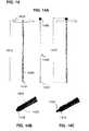
- FIG. 3shows one embodiment of a distal distraction rod
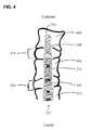
- FIG. 4shows an installed assembly with a distal distraction rod and a proximal distraction rod
- FIG. 5shows one embodiment of a proximal distraction rod
- FIG. 6Ashows an assembly of a distal distraction rod and a proximal distraction rod along with optional plugs
- FIG. 6Bshows a quarter-round cut-away perspective drawing of an assembly with a thrust bearing 680 ;
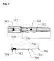
- FIG. 7shows another plug that joins the distal and proximal rods
- FIG. 8shows yet another plug embodiment that uses a separate plug within the proximal rod that does not connect the proximal rod to the distal rod;
- FIG. 9presents a flow chart for the process of imposing two distractions on adjacent intervertebral spaces
- FIG. 10illustrates the use of the present disclosure for a situation calling for the consecutive therapy of three adjacent motion segments
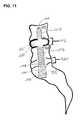
- FIG. 11shows a two-level therapy provided by the sequential installation of two axially implantable rods
- FIG. 12shows a two-level therapy provided by the sequential installation of two axially implantable rods but does so without anchoring to the vertebral body beyond the most cephalad intervertebral disc space to receive the therapy;
- FIG. 13shows the use of the present disclosure to provide dynamic stabilization to two adjacent motion segments
- FIG. 14shows a preferred driver for insertion or removal of plugs as this driver has a retention rod to engage the plug to the distal tip of the driver.
- FIG. 3shows one embodiment of an exemplary distal distraction rod 300 in accordance with the present disclosure.
- FIG. 3Ashows the exterior
- FIG. 3Bprovides a cross section
- FIGS. 3C and 3Dprovide solid surface views in perspective with a longitudinal section removed to expose the interior cavity 304 .
- the operation of the distal distraction rodis best explained in connection with spinal components as shown in FIG. 4 .
- FIG. 4shows three adjacent vertebral bodies called herein distal vertebral body 404 , medial vertebral body 408 , and proximal vertebral body 412 .
- the three vertebral bodiesdefine two adjacent motion segments, comprising intervertebral disc spaces, the distal intervertebral disc space 416 and the proximal intervertebral disc space 420 .
- the proximal vertebral bodyis drawn without a complete outline as the three vertebral bodies are not meant to be limited to specific vertebral bodies.
- the proximal vertebral body 412is not necessarily the sacrum 116 in FIG. 2C as the axial trans-sacral channel 212 may have been extended sufficiently into the spine so that the most distal vertebral body 404 is L3 or higher.
- the distal axial rod 300is comprised of a distal threaded section 308 , a proximal threaded section 312 and in this preferred embodiment, a waist section 316 .
- the use of dissimilar thread pitchesallows for the controlled distraction of two vertebral bodies ( FIG. 4 elements 404 and 408 ) when the distal threaded section 308 is engaged with a distal vertebral body 404 and the proximal threaded section 312 is engaged with the medial vertebral body 408 .
- dissimilar thread pitchesto distract vertebral bodies within a single motion segment is described in co-pending and commonly assigned U.S. patent application Ser. No. 10/309,416 filed on Dec. 3, 2002, now U.S. Pat. No. 6,921,403 which is incorporated herein in its entirety by reference into this disclosure.
- the use of dissimilar thread pitchescan be used in the distal axial rod 300 which is advanced into the vertebral bodies ( 404 and 408 ) by rotating the trailing end of the distal axial rod in the same direction as the “handedness of the screw”.
- the thread on the proximal threaded section 312 and the thread on the distal threaded section 308both extend counterclockwise (or both clockwise) around the elongate body comprising the device, and preferably the distal and proximal threads are self-tapping.
- a distal axial rod 300 having a thread pitch in its distal threaded section 308 that is finer relative to the thread pitch in the threaded proximal section 312causes distraction of the intervertebral disc space 416 between the two engaged vertebral bodies 404 and 408 as each turn of the distal axial rod 300 in the proper direction with respect to handedness of the threads will move the distal axial rod 300 relative to the distal vertebral body 404 a first amount but the distal axial rod 300 will move relative to the more proximal vertebral body 408 (medial vertebral body) a larger amount.
- the ratio of the first amount to the larger amountwill be proportional to the ratio of the pitch of the distal threaded section to the pitch of the proximal threaded section.
- One of skill in the artcan appreciate that in order to effect a more significant distraction; one would select more significantly dissimilar thread pitches than the combination shown in FIG. 3 . As rotation in one direction causes distraction, rotation in the opposite direction causes compression.
- distal axial rod 300include a chip breaker section 320 to facilitate screwing the distal end of the distal distraction rod into the distal vertebral body.
- the leading edge 324 of the thread for the proximal threaded sectiongrows from the minor diameter to the major diameter of the threaded section.
- the cavity 304 of the distal distraction rod 300includes several apertures 332 that extend radially outward at the waist 316 . These apertures can be used to deliver material as part of providing therapy to the motion segment, including bone paste or other materials to promote fusion.
- the distal end 328 of cavity 304is not generally used as an aperture for delivery of therapeutic material as this distal end 328 would be positioned in a vertebral body rather than in an intervertebral space. The opening at the distal end 328 is useful when deploying the distal distraction rod over a guide wire.
- the channel prepared for the insertion of the distal distraction devicecan be of a smaller cross section as the channel enters the distal vertebral body than the cross section of the channel through the medial vertebral body such that the distal section of the distal distraction device can pass through the medial vertebral body without having to be screwed through. While this may appear attractive to pass the distal threaded section through the medial vertebral body in that the bone around the channel is not marred or otherwise weakened, this is not a preferred practice.
- a preferred practiceis to use a sequence of decreasing major diameters, but not necessarily to the extent that the more distal thread sets can be passed through without rotating the rod.
- Rod driver engaging zone 336can be made in one of several configurations known to those of skill in the art to allow a driver to impart rotation to the rod.
- the proximal end of the distal distraction rod 300can be fitted with a female hex head suitable for driving with a driver having a corresponding male hex head.
- a suitable driveris described in priority document No. 60/601,842 filed Aug. 14, 2004 for Method & Apparatus for Multi-Level Stabilization of the Spine and the relevant portions of that document including FIG. 28 are incorporated herein by reference.
- the distal distraction rod 300may be configured to have a set of female extraction threads 348 (for example left-handed metric thread pattern M7) within the proximal end of the cavity 304 .
- the threadmatches the thread on an extraction driver tool.
- the process to extract a previously inserted rodwould start with using the driver to rotate the rod in the counterclockwise direction to start the extraction of the previously inserted rod. (In some cases the extraction could be performed without the initial involvement of the driver to start the disengagement.)
- the extraction toolcan be used to engage the female extraction threads 348 and pull the distraction rod out the rest of the way, if there is a need for such extraction, e.g., in the event of revision or implant selection resizing.
- left-handed threadsis preferred as this allows the extraction of the engaged right-handed threads of the rod to be disengaged by rotating the extraction tool in the normal counterclockwise direction.
- counterclockwise rotationwill cause the left-handed threaded section of the distal tip of the extraction tool to engage with corresponding threads on the rod to be extracted.
- further rotation of the extraction tool in the counterclockwise directionwill disengage the right-handed threads on the rod from the vertebral body. Once the rod is disengaged from the vertebral body, it can be pulled out with the tip of the extraction tool as it will be engaged with the left-handed threads of that tool.
- the left-handed threadsare cut into the polygonal walls of the rod driver engagement zone (perhaps best seen in FIG. 6B described below).
- the use of extraction tools with left-handed threads to remove a rodis not limited to distal distraction rods, but can be used for any installed device that is engaged with right-handed threads including plugs (described below).
- an extraction toolwould have right-handed threads so that clockwise rotation of the extraction tool would disengage such a device.
- FIG. 5shows an exemplary proximal distraction rod 500 for use with the present disclosure. More specifically, FIG. 5A shows the exterior of the proximal distraction rod 500 ; FIG. 5B shows a cross section along the length of the proximal distraction rod 500 ; and FIG. 5C provides a solid surface perspective view of the proximal distraction rod 500 with a longitudinal segment removed.
- Proximal distraction rod 500is comprised of a threaded section 504 and an engagement section 508 . While not shown in this embodiment, one of skill in the art could reduce the length of the threaded section so that the threaded section ends before the beginning of the engagement section, e.g., by including a waist as seen in the exemplary distal distraction rod 300 .
- the threaded section 504has a tapered section 512 and a straight section of thread 516 as this configuration facilitates threading the leading edge of the threaded section into the proximal vertebral body 412 .
- the engagement sectionis not threaded but has a tapered leading edge 520 .
- the tapered leading edge 520 of the engagement section 508engages with the proximal end of the distal distraction rod 300 .
- the engagement section 508proceeds into the distal distraction rod cavity 304 until the shoulder 524 of the proximal distraction rod presses against the trailing edge of the distal distraction rod 300 .
- the distal engagement section 508 of the proximal distraction rodessentially fills the corresponding portion 346 (“engagement zone”) of the bore in the distal distraction rod 300 .
- the specification for the bore size for the portion to receive the cylindrical shankis 0.250 inches (+0.005 inches, ⁇ 0.000 inches) and the specification for the dimension of the cylindrical shank is 0.2495 inches (+0.000 inches, +0.005 inches).
- the angle used for the tapered leading edge 520 portion of the distal engagement section 508is repeated in the corresponding section of the bore 304 .
- This close fit of the leading portion of the proximal distraction rod 500 with the trailing portion of the bore 304 in the distal distraction rodserves to maintain the axial alignment of the two rods to one another while retaining the ability for the proximal distraction rod 500 to rotate relative to the distal distraction rod 300 without imparting a rotation to the distal distraction rod and thus altering the previously imposed distal distraction.
- the amount of distraction imposed on the proximal intervertebral disc space 420is independent of the amount of distraction imposed on the distal intervertebral disc space 416 .
- the pitch of the thread on the threaded portion 504 of the proximal distraction rodis not relevant to the amount of distraction that can be imposed (beyond changing the amount of distraction per turn of the distraction rod).
- the handedness of the thread for the threaded portion 504 of the proximal distraction rodcan be chosen independent of the handedness of the thread used for the proximal distraction rod so that distraction is imparted by rotating the distal distraction rod in a first direction and distraction is imposed by rotating the proximal distraction rod in the opposite direction.
- the cross section of the proximal distraction rod 500can be selected to be sufficiently larger than the major diameter of the proximal threaded section 312 of distal distraction rod 300 to allow the cross section of the channel formed in proximal vertebral body 412 to be sized so that the distal distraction rod 300 can be passed through the proximal vertebral body 412 without being screwed through it or otherwise marring the bone surface exposed by the channel.
- Proximal distraction rod 500has a set of apertures 532 connected to the cavity 528 of the proximal distraction rod 500 . These apertures can be used to distribute therapeutic material as part of the procedure of motion segment fusion. In a preferred embodiment, there are four apertures spaced 90 degrees apart.
- Rod driver engaging section 536can be made in one of several configurations known to those of skill in the art to allow a driver to impart rotation to the rod.
- the proximal end of the proximal distraction rod 500can be fitted with a female hex head suitable for driving with a driver having a corresponding male hex head.
- a suitable driveris described in priority document No. 60/601,842 filed Aug. 14, 2004 for Method & Apparatus for Multi-Level Stabilization of the Spine and the relevant portions of that document including FIG. 28 are incorporated herein by reference.
- a set of female extraction threads 548(preferably left-handed metric threads) at the proximal end of the bore of the proximal distraction rod 500 can be used for the extraction of the proximal distraction rod as discussed in connection with female extraction threads 348 .
- Female threaded section 540 for use in securing a bore plug in the cavity 528will be discussed in greater detail below.
- the purpose of the axial rod plugis to preclude leakage or migration of the osteogenic, osteoconductive, or osteoinductive gel or paste which is inserted by means of an augmentation media (e.g., bone paste; PN material) inserter through apertures from the cavity of the distal or proximate distraction rods into the intervertebral spaces as part of the process of promoting fusion or for other therapeutic purposes.
- an augmentation mediae.g., bone paste; PN material
- the material inserted in this wayis intended to fill available volume not occupied, e.g., by previously introduced autologous bone graft material, in its entirety.
- the plugis fabricated from the same titanium alloy as the axial rod, although it may be formed from other suitable (e.g., biocompatible; polymeric) materials.
- FIG. 6Apresents a representation of a distal distraction rod 300 with a proximal distraction rod 300 shown inserted into the proximal end of the cavity of the distal distraction rod.
- the cavity 304 of the distal distraction rodis connected to apertures 332 and it may be desirable to plug the cavity 304 to prevent or limit the ingress of material into the cavity 304 including the post-treatment ingress of therapeutic material delivered through these apertures.
- a distal rod plug 604is shown (not to scale) with a male threaded section 608 that corresponds to female threaded section 340 .
- the distal rod plug 604can be driven by a hex driver that is appropriately sized to drive a female hex fitting 612 in the trailing edge of the cavity in the distal rod plug 604 .
- a suitable driveris described in priority document No. 60/601,842 filed Aug. 14, 2004 for Method & Apparatus for Multi-Level Stabilization of the Spine and the relevant portions of that document including FIG. 29 are incorporated herein by reference.
- the distal rod plug 604 when installed in the distal distraction rod 300is seated distal to the tapered section 344 of the cavity so that the installed distal rod plug does not interfere with the insertion of the proximal distraction rod 500 into the proximal end of the distal distraction rod 300 .
- the cavity in the distal rod plug 604has a female threaded section 616 which will be described in connection with the proximal distraction rod plug 650 .
- Proximal rod plug 650has male threaded section 654 which is adapted to engage female threaded section 616 of distal rod plug 604 to bind together the assembly including distal distraction rod 300 with distal rod plug 604 along with proximal distraction rod 500 to provide one rigid assembly.
- the proximal rod plug 650does not engage via male threads with female threaded section 540 in the proximal end of the cavity of the proximal distraction rod 500 .
- Proximal rod plug 650in turn has an axial cavity with a female threaded section 658 .
- This threaded cavityis used in connection with a preferred plug driver described below that uses a retention rod to engage with the plug so that it remains engaged with the distal tip of the driver until the driver is disengaged from it.
- the proximal rod plug 650can be driven by a hex driver that is appropriately sized to drive a female hex fitting 662 in the trailing edge of the cavity in the proximal rod plug 650 .
- a suitable driveris described in priority document No. 60/601,842 filed Aug. 14, 2004 for Method & Apparatus for Multi-Level Stabilization of the Spine and the relevant portions of that document including FIG. 29 are incorporated herein by reference.
- FIG. 6Bshows a perspective view with a quarter section removed of an assembled combination of a proximal rod 500 , a distal rod 300 , a distal rod plug 604 and a proximal rod plug 650 that engages with the proximal end of the distal rod plug 604 .
- the componentshave been sized to allow for the use of a thrust bearing 680 which serves to facilitate (e.g., lubricate) the rotation of the proximal rod 500 against the distal rod 300 so that the proximal rod can advance and rotate without imparting rotation to the previously installed distal rod 300 .
- the thrust bearingcan be as shown here as a washer shaped structure. As the thrust bearing will be placed inside a human body, it should be made of a biocompatible material and tolerant of the forces it may see in use. As the thrust bearing is meant to facilitate the rotation of the more proximal rod 500 relative to the more distal rod 300 while under an axial load, the coefficient of sliding friction between the thrust bearing and the rod moving relative to the thrust bearing should be less than the coefficient of sliding friction between two rods as shown in FIG. 6A .
- UHMWPEultra high molecular weight polyethylene
- PEEKpolyether ether ketone
- the perspective view shown in FIG. 6Bincludes the female extraction threads 348 for the distal distraction rod 300 and a better view of the female extraction threads 548 for the proximal distraction rod 500 .
- the female extraction threads such as 548are cut into the most proximal section of a polygonal rod driver engaging section 536 .
- Plug 700has a male threaded section 704 that is adapted to engage with female threaded section 340 when an appropriate driver (not shown in FIG. 7 ) presses upon and rotates the plug through interaction at female socket 708 .
- the cavity of plug 700has female threaded section 712 .
- the tip 716 of plug 700is beyond the apertures 332 so as to block the ingress of material back through those apertures or through apertures 532 of the proximal distraction rod.
- the pair of plugs 604 and 650may be preferable to plug 700 as the insertion of distal rod plug 604 seals off the apertures 332 before the proximal distraction.
- FIG. 8illustrates a third embodiment in which the ingress of material into the proximal distraction rod 500 is limited by the use of a plug 804 that is engaged with the proximal distraction rod 500 rather than the distal distraction rod 300 or a plug within distal distraction rod 300 .
- FIG. 8Ashows a partial cross section
- FIG. 8Bshows a side-elevational perspective view of a proximal distraction rod 500 inserted into the proximal end of a distal distraction rod 300 .
- the distal distraction rod 300is sealed internally with a plug 804 and a proximal rod plug 850 is located in the proximal distraction rod 500 .
- a male threaded section 808 and 858engage corresponding female threaded sections 340 and 540 (best seen in FIG. 6 ) to secure the plug ( 804 or 850 ) into the cavity of the distraction rod.
- the plugsare driven by appropriate drivers that engage the engagement sections 812 and 862 (preferably female hex fittings).
- the tips 816 and 866 of the plugsare placed so that material cannot travel from the apertures back into the longitudinal cavities of the distraction rods.
- FIG. 9presents a flow chart for the process of imposing two distractions on adjacent intervertebral spaces.
- Step 905calls for preparation of the channel to allow for the insertion of the axial distraction rods.
- Step 910calls for engaging the threads from the distal threaded section 308 with the distal vertebral body 404 and the proximal threaded section 312 with the medial vertebral body 408 .
- Step 915calls for rotating the engaged distal distraction rod 300 by applying force to the rod driver engaging zone 336 to selectively impose a specific amount of distraction to the distal intervertebral space through the action of the differences in thread pitch between the distal threaded section 308 and the proximal threaded section 312 .
- the direction of rotation to impose a distractionis a function of the handedness of the threads and whether the finer pitch thread is on the proximal or distal set of threads.
- Step 920calls for applying the desired therapy to the distracted distal intervertebral space 416 .
- This therapymay include providing materials to the distal intervertebral space 416 through the apertures 332 .
- Step 925calls for the optional addition of a distal distraction rod plug such as distal distraction plug 604 .
- a distal distraction rod plugsuch as distal distraction plug 604 . This is optional as some medical providers may opt to not seal the cavity at all and some may rely on a plug applied after the proximal distraction that will seal both axial distraction rod cavities.
- Step 930calls for threading the proximal distraction rod 500 into the proximal vertebral body 412 .
- Step 935calls for rotating the proximal distraction rod 500 until it pushes against the engaged distal distraction rod to impose a specific amount of distraction upon the proximal intervertebral disc space 420 .
- the distal end of the proximal distraction rod 500engages with the proximal end of the cavity in the distal distraction rod 300 so that the application of force by the proximal distraction rod 500 against the distal distraction rod 300 occurs without disturbing the axial alignment of the two distraction rods.
- the amount of distraction imposed on the proximal intervertebral disc spaceis not dependent on the amount of distraction imposed on the distal intervertebral space.
- Step 940calls for the application of the therapy to the proximal intervertebral disc space 420 which may include the insertion of material into the proximal intervertebral space through the apertures 532 .
- Steps 945 , 950 , and 955provide alternatives that can be selected to insert three different types of plugs into the proximal distraction rod.
- Step 945calls for the addition of a proximal distraction rod plug such as shown in FIG. 8 as element 850 .
- a proximal distraction rod plugsuch as shown in FIG. 8 as element 850 .
- Such a plugseals the cavity of the proximal distraction rod but does not serve to join the proximal distraction rod 500 with the distal distraction rod 300 (either directly or indirectly through a distal plug).
- Step 950calls for the insertion and engagement of a proximal distraction plug with the distal distraction rod 300 . This was illustrated by element 700 in FIG. 7 which engages with the female threaded section 340 in the distal distraction rod 300 .
- Step 955calls for the insertion and engagement of a proximal distraction plug with the distal distraction rod plug such as is shown in FIG. 6 as proximal distraction rod plug 650 engages with previously inserted distal distraction rod plug 604 to provide added stability by joining the proximal distraction rod 500 to the distal distraction rod 300 .
- an inter-rod connectorprovides a function of connecting the two rods together whether or not sealing is desired or even provided by the inter-rod connector.
- a connector between two axial distraction rods in keeping with the teachings of the present applicationare intended to be within the scope of the claims whether or not such a connector serves a purpose of acting as a “plug” to limit the ingress of material into the cavity through an aperture as some distraction rods may not have apertures and some therapies may not call for the insertion of therapeutic material through the apertures.
- FIG. 10illustrates the use of the present disclosure for a situation calling for the consecutive therapy of three adjacent motion segments
- the three rod assemblyis shown in outline but includes indications of aspects of the interior cavities including threads, engaging sections for rod drivers and the engagement zones and engagement sections such as engagement zone 346 of the distal distraction rod 300 and the corresponding engagement section 1058 of the next distraction rod (described below).
- the four vertebral bodies illustrated in FIG. 10are the distal vertebral body 404 (L3), distal-medial vertebral body 1004 (L4), proximal-medial vertebral body 1008 (L5), and proximal vertebral body 412 (sacrum).
- the three intervertebral disc spaces between the four vertebral bodiesare the distal intervertebral disc space 416 , the medial intervertebral disc space 1012 , and the proximal intervertebral disc space 420 .
- This embodimenthas three axial distraction rods, the distal distraction rod 300 , a medial distraction rod 1050 , and a proximal distraction rod 550 .
- distal distraction rod 300to distract the distal intervertebral disc space 416 through the use of two sets of threads of different pitches operates as described above.
- the lengths of the distal threaded section 308 , proximal threaded section 312 , and waist 316will be adjusted to be appropriate for whatever motion segment is targeted whether it is L3/L4 instead of L4/L5.
- the threaded section 1054 of the medial distraction rod 1050engages the proximal-medial vertebral body 1008
- continued rotation applied through an engagement between a driver and a corresponding rod driver engagement zone in the proximal cavity of the medial distraction rodcauses the medial distraction rod 1050 to advance and push against the proximal end of the distal distraction rod 300 .
- This advancement and pushingcauses an enlargement of the intervertebral space, in this case the medial intervertebral disc space 1012 .
- the apertures 1062are positioned in the intervertebral space so that therapeutic material can be delivered to this space.
- the distal end of the medial distraction rod 1050will have an engagement section 1058 that fits with close tolerances within the engagement zone 346 proximal end of cavity 304 within the distal distraction rod 300 .
- the medial distraction rod 1050is characterized by having an engagement section 1058 to engage with a correspondingly shaped portion of a cavity of a more distal rod and an engagement zone 1066 in a portion of the cavity at the proximal end of the medial distraction rod 1050 that is adapted for receiving the engagement section 566 of a more proximal distraction rod.
- the medial distraction rod 1050is adapted to push against a more distal distraction rod and to be pushed by a more proximal distraction rod.
- the medial distraction rod 1050would also include a rod driver engagement zone in the proximal end of the cavity for use by a corresponding driver and may include female threads 1072 for use by an extraction tool.
- a proximal rod 550is subsequently threaded into the proximal vertebral body 412 .
- the proximal rod 550 in this embodimenthas apertures 562 in fluid communication with the internal cavity of the proximal distraction rod 550 .
- the proximal distraction rod 550would also include a rod driver engagement zone in the proximal end of the cavity for use by a corresponding driver and may include female threads 572 for use by an extraction tool.
- FIGS. 4 and 10show a series of fusion therapies applied to two or three adjacent motion segments
- the disclosureis not limited to fusion therapy.
- Another class of therapiesworks to provide for some degree of post-operative mobility in the treated motion segment.
- the specifics of the therapeutic aspects of such deviceshave been described in detail in the earlier applications referenced above.
- the focus of this applicationis on the ability to provide therapy to two or more adjacent motion segments, the details of the operation of these axial spinal mobility preservation devices (also termed dynamic stabilization or motion management, or “MM” devices) are not repeated here.
- MMdynamic stabilization or motion management
- FIG. 11shows a two-level therapy provided by the sequential installation of two axially implantable rods.
- Distal rod 1104is comprised of a distal threaded section 1108 , a therapeutic section 1112 , and a proximal threaded section 1116 .
- the distal threaded section 1108 and the proximal threaded section 1116have the same thread pitch in this example and thus the insertion of the distal rod 1104 would not impose a distraction on the distal intervertebral disc space 416 as the distal rod 1104 engaged with distal vertebral body 404 and medial vertebral body 408 .
- Therapeutic section 1112is shown here in outline after material has been inserted into the intervertebral space and retained by device membrane 1120 .
- device membrane 1120In order to make device membrane 1120 distinguishable in this drawing from the components in the motion segment, a small space has been left in the drawing between the device membrane and the other components in the motion segment. This is for purpose of illustration only as the expanded device membrane 1120 would conform to the shape of the intervertebral space. Subsequent illustrations showing analogous device membranes will likewise exaggerate the spacing between the device membrane and other components for the same reason.
- the proximal rod 1150 shown in FIG. 11has a threaded section 1154 and apertures 1158 .
- the engagement between the distal and proximal rodsis not visible in this drawing but can be done in the same manner as described above in connection with FIG. 4 .
- the options for plugsare as described above.
- FIG. 11does illustrate the point that the handedness of the threaded section 1154 does not need to be the same as the handedness of the threads used in the distal rod 1104 in order to achieve a distraction as the more proximal rod will push in the cephalad direction on the implanted more distal rod to increase the axial distance between the vertebral body engaged with the more proximal rod and the vertebral body or bodies engaged with the more distal rod.
- FIG. 12has a distal rod 1204 that has only one threaded section 1208 .
- the distal rodis engaged with the medial vertebral body 408 but not with the distal vertebral body 404 .
- a therapeutic section 1212 of the distal rod 1204extends into the distal intervertebral disc space 416 .
- the deviceAfter insertion of material into expandable device membrane 1220 , the device expands to a conforming fit within the intervertebral disc space 416 . While this distal rod 1204 did not impose a distraction through the use of two threaded sections of dissimilar thread pitch, one of skill in the art will recognize that some distraction could be imposed hydraulically by expanding a membrane within intervertebral disc space 416 .
- Proximal rod 1150 of FIG. 12can be configured internally and operate as described in connection with FIG. 11 .
- FIG. 13illustrates yet another use of the present disclosure to provide therapy to two adjacent spinal motion segments. More specifically, FIG. 13 shows a distal rod 1204 with the various elements described in connection with FIG. 12 . FIG. 13 differs from FIG. 12 in that the proximal rod 1350 is not used to fuse the motion segment of proximal vertebral body 412 , medial vertebral body 408 , and proximal intervertebral disc space 420 as was done in FIGS. 11 and 12 . Instead FIG. 13 shows two adjacent motion segments receiving motion management therapy to provide for post-operative mobility in both of the treated motion segments.
- Proximal rod 1350would be advanced axially towards distal rod 204 by engaging the threaded section 1354 with the proximal vertebral body 412 through use of an appropriate rod driver and a rod driver engagement section in the proximal end of a longitudinal cavity in proximal rod 1350 .
- any subsequent rotation of proximal rod 1350 to advance the rod in the cephalad axial directionwould cause the distal rod 1204 and the engaged medial vertebral body 408 to move axially away from proximal vertebral body 412 .
- materialcould be provided into the proximal end of the cavity in proximal rod 1350 and out apertures in the therapeutic section 1362 of proximal rod 1350 to expand device membrane 1370 .
- motion management therapiesthat used membranes to contain the prosthetic nucleus material inserted into the intervertebral spaces through apertures in the rods
- the disclosureis not limited to these particular types of motion management devices.
- Other motion management therapies as described in the various co-pending applications or issued patents and their priority documentscan be coupled with the teachings of the present disclosure to provide therapy to two or more adjacent spinal motion segments.
- motion management therapies that inject prosthetic nucleus material into the intervertebral space without a membraneare specifically included in the intended range of uses for the present disclosure.
- FIG. 14a&bAnchor Fusion Anchor Fusion Anchor Fusion Anchor 10 PN + DD Anchor MM + PN Anchor MM + PN Anchor PN Anchor MM + PN Anchor PN + DD Anchor MM + PN Anchor Fusion Anchor PN Anchor MM + PN Anchor Fusion Anchor Provisional FIG. 10 PN + DD Anchor Fusion Anchor Fusion Anchor Provisional FIG. 13 PN Anchor Fusion Anchor Fusion Anchor Provisional FIG.
- Table Ais provided to highlight the various non-exhaustive examples of the range of applications of the teachings of the present disclosure.
- the tablereferences the examples in this application and additional examples in Provisional Application No. 60/601,842 filed Aug. 14, 2004 for Method & Apparatus for Multi-Level Stabilization of the Spine which has been incorporated by reference.
- the various drawings referenced in the table and the text associated with those drawings in the provisionalare all incorporated herein by reference.
- anchorrefers to a threaded portion of a device or rod that engages a vertebral body;
- PNrefers to prosthetic nucleus.
- FIG. 14shows a preferred driver for insertion or removal of plugs of the various types discussed above.
- FIG. 14Ashows the driver assembly 1400 .
- the driver assembly 1400has a handle 1404 that is adapted for providing rotation to the driver assembly 1400 and consequently to the driven plug.
- the handle 1404is connected to a driver shaft 1408 to form a driver 1412 with polygonal driver head 1416 as shown in FIG. 14B .
- the driver head 1416is part of a removable tip 1420 that is attached to the driver shaft 1408 , such as by connection pin 1424 .
- Retention rod 1450is comprised of a threaded distal end 1454 and a rotation actuator 1458 , in this case a knob.
- the retention rod 1450can be inserted into the driver shaft 1408 and the threaded distal end 1454 extended through the driver shaft 1408 and out through the driver head 1416 as the retention rod 1450 is longer than the driver 1412 .
- FIG. 14Cshows an enlarged detail of the driver head 1416 with the protruding threaded distal end 1454 .
- the advantage of the driver with retention rod 1450is that a plug can be engaged to the driver 1400 by engaging the threaded distal end 1454 with a corresponding portion of the proximal end of the plug. This can be done by holding the proximal end of the plug adjacent to the threaded distal end 1454 and rotating the rotation actuator 1458 to cause the threaded distal end to rotate relative to the driver shaft 1408 and the held plug. Once the plug is engaged with the threaded distal end 1454 and the driver head 1416 , the distal end of the driver assembly 1400 can be inserted into the channel along with the engaged plug.
- the handlecan be rotated to engage threads on the plug with threads in the device to engage the plug.
- the rotation actuator 1458can be rotated to cause the threaded distal end 1454 of the retention rod 1450 to rotate relative to the driver head 1416 and the plug. Rotation in the proper direction (based on the handedness of the threads used on the threaded distal end 1454 ) will disengage the threaded distal end 1454 from the plug.
- the distal end of the driver assembly 1400can be withdrawn from the channel.
- Extraction of a plug from a devicewould start with putting the threaded distal end 1454 of a retention rod 1450 (which is part of a driver assembly 1400 ) into the channel and adjacent to the proximal end of the plug to be extracted. Rotation of the rotation actuator in the appropriate direction for the threads used will cause the threaded distal end 1454 to engage with the installed plug. After the threaded distal end 1454 is engaged with the plug and the plug is engaged with the driver head 1416 then rotation of the driver assembly 1400 through the use of the handle 1404 will cause the plug to disengage from the device. After the plug is disengaged, it can be removed with the driver assembly as the driver assembly is removed from the channel because the plug is threadedly engaged with the retention rod 1450 .
- the preferred embodiment discussed in detail aboveuses a set of axial distraction rods so that the cross sections of the threaded sections of the rods get progressively smaller.
- An alternativeis that two consecutive sets of threads on two different distraction rods can have the same thread and cross section.
- keyingcan be useful to prevent cross threading. More specifically, it is necessary to “time” the threads so that they engage the bone at the same location, to prevent “cross-threading”. Cross-threading can occur because these are “self-tapping” rods.
- the first set of threads of sufficient size to engage the vertebral bodywill essentially tap the bore through the vertebral body. As the next threaded section reaches the previously tapped vertebral body, cross threading will occur unless the leading edge of the thread enters the track left by the first set of threads in the same place.
- an exchange cannula with a threaded inner diameter that docks with/attaches to the sacrummay be utilized to avoid cross-threading. Each rod can then be readily threaded through the cannula to initially engage the vertebral body at the same location.
- the preferred embodiment of the engagement sectionis a cylinder with a tapered leading edge (frusta-conical) such as shown by engagement section 508 in connection with FIG. 5 .
- frusta-conicaltapered leading edge
- the entire engagement sectioncould be frusta-conical (that is without a cylindrical component), however, the preferred embodiment calls for a rapid taper out to a cylinder to increase the wall thickness of the engagement section to increase the strength of this portion of the rod.
- other shapes that allow for endless rotation of the more proximal rod against the more distal rodwould be viable including a leading edge that resembles a hemisphere.
- a sequence of distraction rodscould include a distal distraction rod, two or more medial distraction rods, and a proximal distraction rod. Assuming that the various rods were sized appropriately for the anatomy of the sequence of motion segments, this would allow for the sequential distraction and selective application of therapy to four or more intervertebral spaces.
Landscapes
- Health & Medical Sciences (AREA)
- Orthopedic Medicine & Surgery (AREA)
- Life Sciences & Earth Sciences (AREA)
- Surgery (AREA)
- Animal Behavior & Ethology (AREA)
- Veterinary Medicine (AREA)
- Biomedical Technology (AREA)
- Heart & Thoracic Surgery (AREA)
- Medical Informatics (AREA)
- Molecular Biology (AREA)
- Nuclear Medicine, Radiotherapy & Molecular Imaging (AREA)
- General Health & Medical Sciences (AREA)
- Public Health (AREA)
- Engineering & Computer Science (AREA)
- Neurology (AREA)
- Prostheses (AREA)
- Surgical Instruments (AREA)
- Electrotherapy Devices (AREA)
- Compression Or Coding Systems Of Tv Signals (AREA)
- Finger-Pressure Massage (AREA)
- Percussion Or Vibration Massage (AREA)
- Aerials With Secondary Devices (AREA)
Abstract
Description
| TABLE A | ||||||||
| Multi-level | L3-L4 | L4-L5 | L5-S1 | |||||
| Configuration | L3 | Disc | L4 | Disc | L5 | Disc | S1 | Figure #s |
| 3-Level | Anchor | MM + PN | Anchor | MM + PN | Anchor | MM + PN | Anchor | |
| Anchor | MM + PN | Anchor | MM + PN | Anchor | Fusion | Anchor | ||
| Anchor | MM + PN | Anchor | Fusion | Anchor | Fusion | Anchor | Provisional | |
| FIG. 14a&b | ||||||||
| Anchor | Fusion | Anchor | Fusion | Anchor | Fusion | Anchor | 10 | |
| PN + DD | Anchor | MM + PN | Anchor | MM + PN | Anchor | |||
| PN | Anchor | MM + PN | Anchor | MM + PN | Anchor | |||
| PN + DD | Anchor | MM + PN | Anchor | Fusion | Anchor | |||
| PN | Anchor | MM + PN | Anchor | Fusion | Anchor | Provisional | ||
| FIG. 10 | ||||||||
| PN + DD | Anchor | Fusion | Anchor | Fusion | Anchor | Provisional | ||
| FIG. 13 | ||||||||
| PN | Anchor | Fusion | Anchor | Fusion | Anchor | Provisional | ||
| FIG. 15 | ||||||||
| 2-Level | Anchor | MM + PN | Anchor | MM + PN | Anchor | |||
| Anchor | MM + PN | Anchor | Fusion | Anchor | 11 | |||
| Anchor | Fusion | Anchor | Fusion | Anchor | 4 could | |||
| apply here | ||||||||
| but 4 is not | ||||||||
| limited to | ||||||||
| these | ||||||||
| vertebrae. | ||||||||
| PN + DD | Anchor | MM + PN | Anchor | |||||
| PN | Anchor | MM + PN | Anchor | 13 | ||||
| PN + DD | Anchor | Fusion | Anchor | Provisional | ||||
| FIG. 12 | ||||||||
| PN | Anchor | Fusion | Anchor | 12 | ||||
Claims (27)
Priority Applications (1)
| Application Number | Priority Date | Filing Date | Title |
|---|---|---|---|
| US12/821,286US8167947B2 (en) | 2002-12-03 | 2010-06-23 | Methods for push distraction and for provision of therapy to adjacent motion segments |
Applications Claiming Priority (8)
| Application Number | Priority Date | Filing Date | Title |
|---|---|---|---|
| US10/309,416US6921403B2 (en) | 2000-02-16 | 2002-12-03 | Method and apparatus for spinal distraction and fusion |
| US51389903P | 2003-10-23 | 2003-10-23 | |
| US60184204P | 2004-08-14 | 2004-08-14 | |
| US10/972,039US7491236B2 (en) | 2000-02-16 | 2004-10-22 | Dual anchor prosthetic nucleus apparatus |
| US11/189,943US7608077B2 (en) | 2000-02-16 | 2005-07-26 | Method and apparatus for spinal distraction and fusion |
| US11/202,655US7776042B2 (en) | 2002-12-03 | 2005-08-13 | Methods and apparatus for provision of therapy to adjacent motion segments |
| US12/339,932US20090105768A1 (en) | 2000-02-16 | 2008-12-19 | Dual anchor prosthetic nucleus apparatus |
| US12/821,286US8167947B2 (en) | 2002-12-03 | 2010-06-23 | Methods for push distraction and for provision of therapy to adjacent motion segments |
Related Parent Applications (1)
| Application Number | Title | Priority Date | Filing Date |
|---|---|---|---|
| US11/202,655DivisionUS7776042B2 (en) | 2002-12-03 | 2005-08-13 | Methods and apparatus for provision of therapy to adjacent motion segments |
Publications (2)
| Publication Number | Publication Date |
|---|---|
| US20110035005A1 US20110035005A1 (en) | 2011-02-10 |
| US8167947B2true US8167947B2 (en) | 2012-05-01 |
Family
ID=35908209
Family Applications (4)
| Application Number | Title | Priority Date | Filing Date |
|---|---|---|---|
| US11/202,655Expired - Fee RelatedUS7776042B2 (en) | 2002-12-03 | 2005-08-13 | Methods and apparatus for provision of therapy to adjacent motion segments |
| US12/821,286Expired - Fee RelatedUS8167947B2 (en) | 2002-12-03 | 2010-06-23 | Methods for push distraction and for provision of therapy to adjacent motion segments |
| US12/851,713Expired - Fee RelatedUS8328847B2 (en) | 2002-12-03 | 2010-08-06 | Assemblies for provision of therapy to motion segments |
| US13/617,030Expired - Fee RelatedUS8523918B2 (en) | 2002-12-03 | 2012-09-14 | Therapy to adjacent motion segments |
Family Applications Before (1)
| Application Number | Title | Priority Date | Filing Date |
|---|---|---|---|
| US11/202,655Expired - Fee RelatedUS7776042B2 (en) | 2002-12-03 | 2005-08-13 | Methods and apparatus for provision of therapy to adjacent motion segments |
Family Applications After (2)
| Application Number | Title | Priority Date | Filing Date |
|---|---|---|---|
| US12/851,713Expired - Fee RelatedUS8328847B2 (en) | 2002-12-03 | 2010-08-06 | Assemblies for provision of therapy to motion segments |
| US13/617,030Expired - Fee RelatedUS8523918B2 (en) | 2002-12-03 | 2012-09-14 | Therapy to adjacent motion segments |
Country Status (8)
| Country | Link |
|---|---|
| US (4) | US7776042B2 (en) |
| EP (1) | EP1786341B1 (en) |
| JP (1) | JP4993500B2 (en) |
| AT (1) | ATE536822T1 (en) |
| AU (1) | AU2005272596B2 (en) |
| CA (1) | CA2577071A1 (en) |
| NO (1) | NO20071350L (en) |
| WO (1) | WO2006020928A2 (en) |
Cited By (5)
| Publication number | Priority date | Publication date | Assignee | Title |
|---|---|---|---|---|
| US20100010490A1 (en)* | 2008-07-09 | 2010-01-14 | Amei Technologies, Inc. | Ankle arthrodesis nail and outrigger assembly |
| US20110004255A1 (en)* | 2009-02-19 | 2011-01-06 | Nextremity Solutions, Llc | Bone joining apparatus and method |
| US20110054473A1 (en)* | 2008-07-09 | 2011-03-03 | Amei Technologies, Inc. | Ankle arthrodesis nail and outrigger assembly |
| US9615873B2 (en) | 2009-02-19 | 2017-04-11 | Nextremity Solutions, Inc. | Bone joining apparatus and method |
| US10667923B2 (en)* | 2016-10-31 | 2020-06-02 | Warsaw Orthopedic, Inc. | Sacro-iliac joint implant system and method |
Families Citing this family (104)
| Publication number | Priority date | Publication date | Assignee | Title |
|---|---|---|---|---|
| US7641657B2 (en)* | 2003-06-10 | 2010-01-05 | Trans1, Inc. | Method and apparatus for providing posterior or anterior trans-sacral access to spinal vertebrae |
| US7744599B2 (en) | 2000-02-16 | 2010-06-29 | Trans1 Inc. | Articulating spinal implant |
| US6558390B2 (en) | 2000-02-16 | 2003-05-06 | Axiamed, Inc. | Methods and apparatus for performing therapeutic procedures in the spine |
| US6558386B1 (en)* | 2000-02-16 | 2003-05-06 | Trans1 Inc. | Axial spinal implant and method and apparatus for implanting an axial spinal implant within the vertebrae of the spine |
| US6899716B2 (en)* | 2000-02-16 | 2005-05-31 | Trans1, Inc. | Method and apparatus for spinal augmentation |
| US7014633B2 (en)* | 2000-02-16 | 2006-03-21 | Trans1, Inc. | Methods of performing procedures in the spine |
| US20030191474A1 (en)* | 2000-02-16 | 2003-10-09 | Cragg Andrew H. | Apparatus for performing a discectomy through a trans-sacral axial bore within the vertebrae of the spine |
| US7717958B2 (en) | 2000-02-16 | 2010-05-18 | Trans1, Inc. | Prosthetic nucleus apparatus |
| US6740090B1 (en)* | 2000-02-16 | 2004-05-25 | Trans1 Inc. | Methods and apparatus for forming shaped axial bores through spinal vertebrae |
| DK1578315T3 (en)* | 2000-02-16 | 2008-10-06 | Trans1 Inc | Device for vertebral column distribution and fusion |
| US7938836B2 (en) | 2003-10-23 | 2011-05-10 | Trans1, Inc. | Driver assembly for simultaneous axial delivery of spinal implants |
| GB0108044D0 (en)* | 2001-03-30 | 2001-05-23 | British Telecomm | Application synchronisation |
| US7776042B2 (en) | 2002-12-03 | 2010-08-17 | Trans1 Inc. | Methods and apparatus for provision of therapy to adjacent motion segments |
| AU2004283727A1 (en)* | 2003-10-23 | 2005-05-06 | Trans1 Inc. | Tools and tool kits for performing minimally invasive procedures on the spine |
| US7959634B2 (en)* | 2004-03-29 | 2011-06-14 | Soteira Inc. | Orthopedic surgery access devices |
| JP2008508980A (en)* | 2004-08-09 | 2008-03-27 | トランス1,インク. | Nucleus nucleus prosthesis device and method |
| US20180228621A1 (en) | 2004-08-09 | 2018-08-16 | Mark A. Reiley | Apparatus, systems, and methods for the fixation or fusion of bone |
| US8425570B2 (en) | 2004-08-09 | 2013-04-23 | Si-Bone Inc. | Apparatus, systems, and methods for achieving anterior lumbar interbody fusion |
| US9949843B2 (en) | 2004-08-09 | 2018-04-24 | Si-Bone Inc. | Apparatus, systems, and methods for the fixation or fusion of bone |
| US20070156241A1 (en) | 2004-08-09 | 2007-07-05 | Reiley Mark A | Systems and methods for the fixation or fusion of bone |
| US20060036251A1 (en) | 2004-08-09 | 2006-02-16 | Reiley Mark A | Systems and methods for the fixation or fusion of bone |
| US8414648B2 (en) | 2004-08-09 | 2013-04-09 | Si-Bone Inc. | Apparatus, systems, and methods for achieving trans-iliac lumbar fusion |
| US9662158B2 (en) | 2004-08-09 | 2017-05-30 | Si-Bone Inc. | Systems and methods for the fixation or fusion of bone at or near a sacroiliac joint |
| US8388667B2 (en) | 2004-08-09 | 2013-03-05 | Si-Bone, Inc. | Systems and methods for the fixation or fusion of bone using compressive implants |
| WO2006058221A2 (en) | 2004-11-24 | 2006-06-01 | Abdou Samy M | Devices and methods for inter-vertebral orthopedic device placement |
| US7828828B2 (en)* | 2005-04-14 | 2010-11-09 | Warsaw Orthopedic, Inc | Intervertebral joint |
| US7951198B2 (en)* | 2005-05-10 | 2011-05-31 | Acumed Llc | Bone connector with pivotable joint |
| WO2011092681A1 (en)* | 2010-01-26 | 2011-08-04 | Sialo-Lite Ltd. | Dental implants, devices and methods associated with dental implantation procedures |
| WO2007021772A2 (en)* | 2005-08-09 | 2007-02-22 | Trans1, Inc. | Exchange system for axial spinal procedures |
| EP2012686B1 (en)* | 2006-04-18 | 2013-10-02 | Joseph Nicholas Logan | Spinal rod system |
| US7931651B2 (en)* | 2006-11-17 | 2011-04-26 | Wake Lake University Health Sciences | External fixation assembly and method of use |
| WO2008076330A1 (en) | 2006-12-15 | 2008-06-26 | Soteira, Inc. | Drills and methods for vertebrostenting |
| US8057516B2 (en)* | 2007-03-21 | 2011-11-15 | Zimmer Spine, Inc. | Spinal stabilization system with rigid and flexible elements |
| FR2916624B1 (en)* | 2007-05-29 | 2009-08-21 | Small Bone Innovations Interna | BONE SCREW, IN PARTICULAR OSTEOSYNTHESIS |
| AU2008316604B2 (en)* | 2007-10-25 | 2014-11-06 | Smith & Nephew, Inc. | Anchor assembly |
| KR101045933B1 (en)* | 2008-05-02 | 2011-07-01 | 김가브리엘민 | Calibration device |
| WO2009155319A1 (en) | 2008-06-17 | 2009-12-23 | Soteira, Inc. | Devices and methods for fracture reduction |
| EP2140824B1 (en)* | 2008-07-01 | 2016-06-08 | Biedermann Technologies GmbH & Co. KG | Cannulated bone anchor with plug member and tool for inserting the plug member into the bone anchor |
| US20100010633A1 (en)* | 2008-07-10 | 2010-01-14 | Kyphon Sarl | Deployable Arc Fusion Cage and Methods Associated Therewith |
| US8974494B2 (en) | 2008-07-17 | 2015-03-10 | Smith & Nephew, Inc. | Surgical devices |
| US8409208B2 (en)* | 2008-10-04 | 2013-04-02 | M. Samy Abdou | Device and method to access the anterior column of the spine |
| US20100114315A1 (en)* | 2008-10-31 | 2010-05-06 | Manderson Easton L | Intramedullary locked compression screw for stabilization and union of complex ankle and subtalar deformities |
| US10045860B2 (en) | 2008-12-19 | 2018-08-14 | Amicus Design Group, Llc | Interbody vertebral prosthetic device with self-deploying screws |
| WO2010111246A1 (en) | 2009-03-23 | 2010-09-30 | Soteira, Inc. | Devices and methods for vertebrostenting |
| ES2552380T3 (en) | 2009-07-01 | 2015-11-27 | Biedermann Technologies Gmbh & Co. Kg | Instruments for use with a bone anchor with closure element |
| US8747472B2 (en)* | 2009-08-14 | 2014-06-10 | Baxano Surgical, Inc. | Spinal therapy device with fixated distraction distance |
| JP2013510659A (en) | 2009-11-10 | 2013-03-28 | スミス アンド ネフュー インコーポレーテッド | Tissue repair device |
| US20110112373A1 (en)* | 2009-11-10 | 2011-05-12 | Trans1 Inc. | Soft tissue access apparatus and methods for spinal surgery |
| US8764806B2 (en) | 2009-12-07 | 2014-07-01 | Samy Abdou | Devices and methods for minimally invasive spinal stabilization and instrumentation |
| US8758416B2 (en)* | 2010-03-10 | 2014-06-24 | Paul J. Pagano | Odontoid fracture dynamic compression apparatus and method |
| US20130123862A1 (en)* | 2010-10-10 | 2013-05-16 | Gregory Anderson | Arthrodesis implant and buttressing apparatus and method |
| TW201231013A (en)* | 2010-10-13 | 2012-08-01 | Synthes Gmbh | Intervertebral implant |
| EP2685921B1 (en)* | 2011-03-18 | 2019-03-13 | Raed M. Ali, M.D., Inc. | Transpedicular access to intervertebral spaces and related spinal fusion systems and methods |
| US9265620B2 (en) | 2011-03-18 | 2016-02-23 | Raed M. Ali, M.D., Inc. | Devices and methods for transpedicular stabilization of the spine |
| US8845728B1 (en) | 2011-09-23 | 2014-09-30 | Samy Abdou | Spinal fixation devices and methods of use |
| CN103997904A (en)* | 2011-12-13 | 2014-08-20 | 希尔氏宠物营养品公司 | Compositions and methods for treating dental conditions |
| US9463052B2 (en) | 2012-01-12 | 2016-10-11 | Integrity Implants Inc. | Access assembly for anterior and lateral spinal procedures |
| US20130226240A1 (en) | 2012-02-22 | 2013-08-29 | Samy Abdou | Spinous process fixation devices and methods of use |
| US9044321B2 (en) | 2012-03-09 | 2015-06-02 | Si-Bone Inc. | Integrated implant |
| US10363140B2 (en) | 2012-03-09 | 2019-07-30 | Si-Bone Inc. | Systems, device, and methods for joint fusion |
| ES2770824T3 (en) | 2012-03-19 | 2020-07-03 | Amicus Design Group Llc | Intervertebral fusion prosthetic and orthopedic device with self-deploying anchors |
| US9566165B2 (en) | 2012-03-19 | 2017-02-14 | Amicus Design Group, Llc | Interbody vertebral prosthetic and orthopedic fusion device with self-deploying anchors |
| EP3818947B1 (en) | 2012-05-04 | 2023-08-30 | SI-Bone, Inc. | Fenestrated implant |
| WO2013173873A1 (en)* | 2012-05-22 | 2013-11-28 | Austofix Group Limited | Bone fixation device |
| US9198767B2 (en) | 2012-08-28 | 2015-12-01 | Samy Abdou | Devices and methods for spinal stabilization and instrumentation |
| US9320617B2 (en) | 2012-10-22 | 2016-04-26 | Cogent Spine, LLC | Devices and methods for spinal stabilization and instrumentation |
| US9962190B2 (en)* | 2013-01-15 | 2018-05-08 | Friedrich Müller | MTV implantation set |
| US10687962B2 (en) | 2013-03-14 | 2020-06-23 | Raed M. Ali, M.D., Inc. | Interbody fusion devices, systems and methods |
| US9861495B2 (en) | 2013-03-14 | 2018-01-09 | Raed M. Ali, M.D., Inc. | Lateral interbody fusion devices, systems and methods |
| WO2014159225A2 (en)* | 2013-03-14 | 2014-10-02 | Baxano Surgical, Inc. | Spinal implants and implantation system |
| WO2014145902A1 (en) | 2013-03-15 | 2014-09-18 | Si-Bone Inc. | Implants for spinal fixation or fusion |
| US20140343616A1 (en)* | 2013-04-22 | 2014-11-20 | Daniel Sellers | Arthrodesis compression device |
| EP2856958A1 (en)* | 2013-10-07 | 2015-04-08 | Arthrex Inc | Cannulated bone screw |
| US9839448B2 (en) | 2013-10-15 | 2017-12-12 | Si-Bone Inc. | Implant placement |
| US11147688B2 (en) | 2013-10-15 | 2021-10-19 | Si-Bone Inc. | Implant placement |
| US20150139428A1 (en)* | 2013-11-20 | 2015-05-21 | Knowles IPC (M) Snd. Bhd. | Apparatus with a speaker used as second microphone |
| WO2015168478A1 (en)* | 2014-05-01 | 2015-11-05 | Lorio Morgan Packard | Sacroiliac joint fastener, systems, and methods of using the same |
| EP3172147A4 (en)* | 2014-07-24 | 2018-03-14 | Magtube, LLC | Using magnetism to secure the detachable spray-extension tube to an aerosol spray can to prevent misplacement or loss |
| JP6542362B2 (en) | 2014-09-18 | 2019-07-10 | エスアイ−ボーン・インコーポレイテッドSi−Bone, Inc. | Matrix implant |
| US10166033B2 (en) | 2014-09-18 | 2019-01-01 | Si-Bone Inc. | Implants for bone fixation or fusion |
| EP3258868B1 (en)* | 2015-02-16 | 2019-08-21 | Akros Medical, Inc. | Devices and systems for semi-rigid bone fixation |
| US10376206B2 (en) | 2015-04-01 | 2019-08-13 | Si-Bone Inc. | Neuromonitoring systems and methods for bone fixation or fusion procedures |
| US10492838B2 (en)* | 2015-07-13 | 2019-12-03 | IntraFuse, LLC | Flexible bone implant |
| US10154863B2 (en)* | 2015-07-13 | 2018-12-18 | IntraFuse, LLC | Flexible bone screw |
| US10058350B2 (en) | 2015-09-24 | 2018-08-28 | Integrity Implants, Inc. | Access assembly for anterior and lateral spinal procedures |
| US10857003B1 (en) | 2015-10-14 | 2020-12-08 | Samy Abdou | Devices and methods for vertebral stabilization |
| US9924935B2 (en) | 2015-10-23 | 2018-03-27 | Smith & Nephew, Inc. | Suture anchor assembly with slip fit tip |
| US10744000B1 (en) | 2016-10-25 | 2020-08-18 | Samy Abdou | Devices and methods for vertebral bone realignment |
| US10973648B1 (en) | 2016-10-25 | 2021-04-13 | Samy Abdou | Devices and methods for vertebral bone realignment |
| US20180289504A1 (en)* | 2017-04-11 | 2018-10-11 | Quandary Medical, Llc | Fenestrated spinal implant |
| US11116519B2 (en) | 2017-09-26 | 2021-09-14 | Si-Bone Inc. | Systems and methods for decorticating the sacroiliac joint |
| ES3011907T3 (en) | 2018-03-28 | 2025-04-08 | Si Bone Inc | Threaded implants for use across bone segments |
| US11179248B2 (en) | 2018-10-02 | 2021-11-23 | Samy Abdou | Devices and methods for spinal implantation |
| US11369419B2 (en) | 2019-02-14 | 2022-06-28 | Si-Bone Inc. | Implants for spinal fixation and or fusion |
| EP4613244A2 (en) | 2019-02-14 | 2025-09-10 | SI-Bone Inc. | Implants for spinal fixation and or fusion |
| US20200281736A1 (en)* | 2019-03-04 | 2020-09-10 | K2M, Inc. | Intervertebral Implant Assembly and Instruments Therefor |
| ES1232501Y (en)* | 2019-05-21 | 2019-10-08 | Inst Biomecanico De Barcelona S L | INTERVERTEBRAL STABILIZATION SCREW |
| JP7646654B2 (en) | 2019-11-21 | 2025-03-17 | エスアイ-ボーン・インコーポレイテッド | Rod coupling assembly for bone stabilization construct - Patent application |
| AU2020392121B2 (en) | 2019-11-27 | 2025-05-22 | Si-Bone, Inc. | Bone stabilizing implants and methods of placement across SI joints |
| EP4072452A4 (en) | 2019-12-09 | 2023-12-20 | SI-Bone, Inc. | Sacro-iliac joint stabilizing implants and methods of implantation |
| US20210177477A1 (en)* | 2019-12-13 | 2021-06-17 | Alliance Partners Llc | Cannulated aspiration screw device and methods of use thereof |
| EP4259015A4 (en) | 2020-12-09 | 2024-09-11 | SI-Bone, Inc. | SACROILIAC JOINT STABILIZATION IMPLANTS AND METHODS OF IMPLANTATION |
| CN115137422B (en)* | 2022-07-29 | 2024-11-12 | 长沙市中心医院 | A percutaneously installed axial distraction system for assisting minimally invasive surgery of calcaneal fractures |
| WO2025038769A1 (en) | 2023-08-15 | 2025-02-20 | Si-Bone Inc. | Pelvic stabilization implants, methods of use and manufacture |
Citations (221)
| Publication number | Priority date | Publication date | Assignee | Title |
|---|---|---|---|---|
| US1442051A (en) | 1921-05-10 | 1923-01-16 | William L Cummings | Radium needle |
| US2336338A (en) | 1932-04-20 | 1943-12-07 | John A Zublin | Apparatus for drilling bores deviating from existing well bores |
| US2586556A (en) | 1946-11-23 | 1952-02-19 | Mullikin Alfred | Flexible binder post |
| US3367326A (en) | 1965-06-15 | 1968-02-06 | Calvin H. Frazier | Intra spinal fixation rod |
| US3454006A (en) | 1966-01-28 | 1969-07-08 | Weck & Co Inc Edward | Intravenous catheter-needle assembly provided with needle bushing guide |
| US3598108A (en) | 1969-02-28 | 1971-08-10 | Khosrow Jamshidi | Biopsy technique and biopsy device |
| US3620216A (en) | 1969-06-25 | 1971-11-16 | Abbott Lab | Implant trocar |
| US3628524A (en) | 1969-02-28 | 1971-12-21 | Khosrow Jamshidi | Biopsy needle |
| US3788320A (en) | 1972-02-25 | 1974-01-29 | Kendall & Co | Spinal needle |
| US3837347A (en) | 1972-04-20 | 1974-09-24 | Electro Catheter Corp | Inflatable balloon-type pacing probe |
| US3892232A (en) | 1973-09-24 | 1975-07-01 | Alonzo J Neufeld | Method and apparatus for performing percutaneous bone surgery |
| US3893445A (en) | 1974-01-09 | 1975-07-08 | Becton Dickinson Co | Bone marrow biopsy instrument |
| US3993079A (en) | 1974-12-14 | 1976-11-23 | Henriques De Gatztanondo Carlo | Device for percutaneous paracentesis, injection, drainage and catheterization |
| US4046144A (en) | 1975-09-18 | 1977-09-06 | Mcfarlane Richard H | Catheter placement assembly |
| US4175555A (en) | 1977-02-24 | 1979-11-27 | Interfix Limited | Bone screw |
| US4202332A (en) | 1977-01-26 | 1980-05-13 | Bernd Tersteegen | Double lumen catheter |
| US4266555A (en) | 1979-11-09 | 1981-05-12 | Khosrow Jamshidi | Biopsy needle with stylet and cannula orientation |
| US4276874A (en) | 1978-11-15 | 1981-07-07 | Datascope Corp. | Elongatable balloon catheter |
| US4309777A (en) | 1980-11-13 | 1982-01-12 | Patil Arun A | Artificial intervertebral disc |
| US4513754A (en) | 1978-03-03 | 1985-04-30 | Southland Instruments, Inc. | Biopsy and aspiration unit with a replaceable cannula |
| US4518383A (en) | 1982-08-06 | 1985-05-21 | Evans John M | Instrument and method for epidural and spinal anaesthesia |
| US4553273A (en) | 1983-11-23 | 1985-11-19 | Henry Ford Hospital | Vertebral body prosthesis and spine stabilizing method |
| US4554914A (en) | 1983-10-04 | 1985-11-26 | Kapp John P | Prosthetic vertebral body |
| US4573448A (en) | 1983-10-05 | 1986-03-04 | Pilling Co. | Method for decompressing herniated intervertebral discs |
| US4607632A (en) | 1984-04-30 | 1986-08-26 | Aller-Screen, Inc. | Skin testing device with funnel loading |
| US4609370A (en) | 1983-06-20 | 1986-09-02 | Morrison Peter C | Surgical needle assembly and apparatus for attachment on a surgical needle assembly |
| US4636217A (en) | 1985-04-23 | 1987-01-13 | Regents Of The University Of Minnesota | Anterior spinal implant |
| US4650466A (en) | 1985-11-01 | 1987-03-17 | Angiobrade Partners | Angioplasty device |
| US4654030A (en) | 1986-02-24 | 1987-03-31 | Endotherapeutics | Trocar |
| US4657550A (en) | 1984-12-21 | 1987-04-14 | Daher Youssef H | Buttressing device usable in a vertebral prosthesis |
| US4721506A (en) | 1986-11-07 | 1988-01-26 | Teves Leonides Y | Flat-inclined tip needle |
| US4772266A (en) | 1987-05-04 | 1988-09-20 | Catheter Technology Corp. | Catheter dilator/sheath assembly and method |
| US4790303A (en) | 1987-03-11 | 1988-12-13 | Acromed Corporation | Apparatus and method for securing bone graft |
| US4808155A (en) | 1986-02-27 | 1989-02-28 | Mahurkar Sakharam D | Simple double lumen catheter |
| US4854797A (en) | 1988-10-05 | 1989-08-08 | Ford Motor Company | Threaded fastener with resilient linking means |
| US4858601A (en) | 1988-05-27 | 1989-08-22 | Glisson Richard R | Adjustable compression bone screw |
| US4862891A (en) | 1988-03-14 | 1989-09-05 | Canyon Medical Products | Device for sequential percutaneous dilation |
| US4873978A (en) | 1987-12-04 | 1989-10-17 | Robert Ginsburg | Device and method for emboli retrieval |
| US4922602A (en) | 1981-03-16 | 1990-05-08 | Creative Research And Manufacturing, Inc. | Method of manufacturing a biopsy needle |
| US4969887A (en) | 1986-09-08 | 1990-11-13 | Sodhi Jitendra S | Self-retaining nail kit for repairing a fractured neck of femur |
| US4969888A (en) | 1989-02-09 | 1990-11-13 | Arie Scholten | Surgical protocol for fixation of osteoporotic bone using inflatable device |
| US4994036A (en) | 1988-09-09 | 1991-02-19 | B. Braun Melsungen Ag | Catheter set for spinal anaesthesia |
| US5002576A (en) | 1988-06-06 | 1991-03-26 | Mecron Medizinische Produkte Gmbh | Intervertebral disk endoprosthesis |
| US5002546A (en) | 1987-04-13 | 1991-03-26 | Romano Jack W | Curved bore drilling apparatus |
| US5009659A (en) | 1989-10-30 | 1991-04-23 | Schneider (Usa) Inc. | Fiber tip atherectomy catheter |
| US5019080A (en)* | 1990-02-13 | 1991-05-28 | Trextron Inc. | Drive system for prosthetic fasteners |
| US5059193A (en) | 1989-11-20 | 1991-10-22 | Spine-Tech, Inc. | Expandable spinal implant and surgical method |
| US5061137A (en) | 1991-04-29 | 1991-10-29 | Ford Motor Company | Fastener with resilient linking means |
| US5090419A (en) | 1990-08-23 | 1992-02-25 | Aubrey Palestrant | Apparatus for acquiring soft tissue biopsy specimens |
| US5102276A (en) | 1990-07-12 | 1992-04-07 | Ford Motor Company | Removable fastener with elastic linking means |
| US5108430A (en) | 1987-02-20 | 1992-04-28 | Biagio Ravo | Implantable reservoir adapted to receive and store structural devices therein |
| US5147404A (en) | 1987-12-07 | 1992-09-15 | Downey Ernest L | Vertebra prosthesis |
| US5169387A (en) | 1991-04-03 | 1992-12-08 | Kronner Richard F | Method and apparatus for catheterization of a body cavity |
| US5231910A (en) | 1990-11-28 | 1993-08-03 | C. & E. Fein Gmbh & Co. | Device for producing u-shaped surface channels in sheeting |
| US5246458A (en) | 1992-10-07 | 1993-09-21 | Graham Donald V | Artificial disk |
| US5261888A (en) | 1989-12-18 | 1993-11-16 | Wisap-Gesellschaft Fur Wissenschaftlichen Apparatebau Mbh | Trocar sleeve |
| US5279553A (en) | 1992-04-02 | 1994-01-18 | Martin J. Winkler | Transpyloric jejunostomy cannulating system |
| US5290247A (en) | 1991-05-21 | 1994-03-01 | C. R. Bard, Inc. | Intracoronary exchange apparatus and method |
| US5295974A (en) | 1991-01-07 | 1994-03-22 | Laughlin D Michael O | Shielded hypodermic needle with I.V. cannula |
| US5336223A (en) | 1993-02-04 | 1994-08-09 | Rogers Charles L | Telescoping spinal fixator |
| US5338297A (en) | 1993-03-19 | 1994-08-16 | Kocur Medical Associates | Cervical canal balloon catheter |
| US5344315A (en) | 1993-12-02 | 1994-09-06 | Hamilton Ortho Inc. | Multi-strand orthodontic arch wires and methods for use thereof |
| US5370653A (en) | 1993-07-22 | 1994-12-06 | Micro Therapeutics, Inc. | Thrombectomy method and apparatus |
| US5376094A (en) | 1993-08-19 | 1994-12-27 | Boston Scientific Corporation | Improved actuating handle with pulley system for providing mechanical advantage to a surgical working element |
| US5380292A (en) | 1993-12-22 | 1995-01-10 | Wilson-Cook Medical, Inc. | Gastrointestinal needle mechanism |
| US5385561A (en) | 1994-01-18 | 1995-01-31 | Bard International, Inc. | Apparatus and method for injecting a viscous material into the tissue of a patient |
| US5427115A (en) | 1993-09-13 | 1995-06-27 | Boston Scientific Corporation | Apparatus for stricture diagnosis and treatment |
| US5431676A (en) | 1993-03-05 | 1995-07-11 | Innerdyne Medical, Inc. | Trocar system having expandable port |
| US5445140A (en) | 1993-06-07 | 1995-08-29 | United States Surgical Corporation | Endoscopic surgical device |
| US5445619A (en) | 1994-09-23 | 1995-08-29 | Becton, Dickinson And Company | Shielded needle assembly |
| US5476467A (en) | 1994-06-14 | 1995-12-19 | Benoist; Louis A. | Surgical hammer for driving K-wires |
| US5478328A (en) | 1992-05-22 | 1995-12-26 | Silverman; David G. | Methods of minimizing disease transmission by used hypodermic needles, and hypodermic needles adapted for carrying out the method |
| US5490859A (en) | 1992-11-13 | 1996-02-13 | Scimed Life Systems, Inc. | Expandable intravascular occlusion material removal devices and methods of use |
| US5515871A (en) | 1990-09-28 | 1996-05-14 | Sulzer Brothers Ltd. | Hollow needle for medical use and a laser method for manufacturing |
| US5535756A (en) | 1994-01-06 | 1996-07-16 | Parasher; Vinod K. | Catheter with simultaneous brush cytology and scrape biopsy capability |
| US5571192A (en) | 1994-07-02 | 1996-11-05 | Heinrich Ulrich | Prosthetic vertebral implant |
| US5571133A (en) | 1995-06-01 | 1996-11-05 | Yoon; Inbae | Penetrating instrument with sequential indication of entry into anatomical cavities |
| US5591170A (en) | 1994-10-14 | 1997-01-07 | Genesis Orthopedics | Intramedullary bone cutting saw |
| US5669882A (en) | 1996-04-23 | 1997-09-23 | Pyles; Stephen | Curved epidural needle system |
| US5685857A (en) | 1996-03-22 | 1997-11-11 | Plc Medical Systems, Inc. | Thoracoscopic cannula system |
| US5685877A (en) | 1995-09-19 | 1997-11-11 | Anthony Pagedas | Mutiple tool laparoscopic surgical instrument |
| US5685852A (en) | 1992-03-30 | 1997-11-11 | Symbiosis Corporation | Needle assembly and methods useful for epidural anesthesia |
| US5702453A (en) | 1994-12-09 | 1997-12-30 | Sofamor Danek Group | Adjustable vertebral body replacement |
| US5702455A (en) | 1996-07-03 | 1997-12-30 | Saggar; Rahul | Expandable prosthesis for spinal fusion |
| US5718237A (en) | 1993-11-15 | 1998-02-17 | Haaga; John R. | Biopsy needle |
| US5722423A (en) | 1994-12-30 | 1998-03-03 | Annex Medical, Inc. | Tissue removing device |
| US5733284A (en) | 1993-08-27 | 1998-03-31 | Paulette Fairant | Device for anchoring spinal instrumentation on a vertebra |
| US5735813A (en) | 1996-10-23 | 1998-04-07 | Danron, Inc. | Double lumen introducing needle |
| US5743912A (en) | 1995-08-23 | 1998-04-28 | Biomat | Upper femoral epiphysis osteosynthesis implant |
| US5807277A (en) | 1995-12-15 | 1998-09-15 | Swaim; William R. | Biopsy hand tool for capturing tissue sample |
| US5807318A (en) | 1994-07-28 | 1998-09-15 | Heartport, Inc. | Method of perfusing the coronary vasculature |
| US5810788A (en) | 1995-11-15 | 1998-09-22 | Racz; Gabor J. | R-X needle |
| US5827285A (en)* | 1996-12-12 | 1998-10-27 | Bramlet; Dale G. | Multipiece interfragmentary fixation assembly |
| US5843048A (en) | 1996-08-06 | 1998-12-01 | The Kendall Company | Epidural catheter needle |
| US5882329A (en) | 1997-02-12 | 1999-03-16 | Prolifix Medical, Inc. | Apparatus and method for removing stenotic material from stents |
| US5902279A (en) | 1993-04-20 | 1999-05-11 | Advanced Cytometrix, Inc. | Aspiration needle and method |
| US5916208A (en) | 1996-06-06 | 1999-06-29 | Luther Medical Products, Inc. | Hard tip over-the-needle catheter and method of manufacturing the same |
| US5916267A (en) | 1997-04-07 | 1999-06-29 | Arthit Sitiso | Anterior spinal implant system for vertebral body prosthesis |
| US5919172A (en) | 1996-07-17 | 1999-07-06 | Becton, Dickinson And Company | Hypodermic needle having a differential surface finish |
| US5921971A (en) | 1996-09-13 | 1999-07-13 | Boston Scientific Corporation | Single operator exchange biliary catheter |
| US5928239A (en) | 1998-03-16 | 1999-07-27 | University Of Washington | Percutaneous surgical cavitation device and method |
| US5935131A (en) | 1990-06-28 | 1999-08-10 | Bonutti; Peter M. | Apparatus and method for tissue removal |
| US5937524A (en) | 1997-10-14 | 1999-08-17 | Hornsby; Colby | Tool for cutting melon from rind |
| US5954671A (en) | 1998-04-20 | 1999-09-21 | O'neill; Michael J. | Bone harvesting method and apparatus |
| US5972015A (en) | 1997-08-15 | 1999-10-26 | Kyphon Inc. | Expandable, asymetric structures for deployment in interior body regions |
| US5979056A (en) | 1995-06-07 | 1999-11-09 | Andrews; Edward A. | Body shaving device with curved razor blade strip |
| US5989290A (en) | 1995-05-24 | 1999-11-23 | Biedermann; Lutz | Height-adjustable artificial vertebral body |
| US6010495A (en) | 1995-03-17 | 2000-01-04 | Tilton, Jr.; Eugene B. | Instrumentation for endoscopic surgical insertion and application of liquid, gel and like material |
| US6036696A (en) | 1997-12-19 | 2000-03-14 | Stryker Technologies Corporation | Guide-pin placement device and method of use |
| US6036658A (en) | 1997-07-10 | 2000-03-14 | Leet; Richard A. | Cervical tissue sampling device and method |
| US6053916A (en)* | 1999-02-17 | 2000-04-25 | Moore; Michael R. | Sacroiliac implant |
| US6056749A (en) | 1999-03-15 | 2000-05-02 | Spineology, Inc. | Method and device for fixing and correcting spondylolisthesis anteriorly |
| US6086589A (en)* | 1999-02-02 | 2000-07-11 | Spineology, Inc. | Method and device for fixing spondylolisthesis posteriorly |
| US6093196A (en) | 1998-02-05 | 2000-07-25 | Olympus Optical Co., Ltd. | Basket type grasping tool for surgery |
| US6093205A (en) | 1997-06-25 | 2000-07-25 | Bridport-Gundry Plc C/O Pearsalls Implants | Surgical implant |
| US6113614A (en) | 1998-05-05 | 2000-09-05 | Ensurg, Inc. | Medical device for dissolution of tissue within the human body |
| USRE36857E (en) | 1988-03-10 | 2000-09-05 | Scimed Life Systems, Inc. | Interlocking peel-away dilation catheter |
| US6127597A (en) | 1997-03-07 | 2000-10-03 | Discotech N.V. | Systems for percutaneous bone and spinal stabilization, fixation and repair |
| US6159179A (en) | 1999-03-12 | 2000-12-12 | Simonson; Robert E. | Cannula and sizing and insertion method |
| US6159212A (en) | 1999-08-02 | 2000-12-12 | Schoedinger, Iii; George R. | Surgical tool and method to reduce vertebral displacement |
| US6187000B1 (en) | 1998-08-20 | 2001-02-13 | Endius Incorporated | Cannula for receiving surgical instruments |
| US6217509B1 (en) | 1996-03-22 | 2001-04-17 | Sdgi Holdings, Inc. | Devices and methods for percutaneous surgery |
| US6235043B1 (en) | 1994-01-26 | 2001-05-22 | Kyphon, Inc. | Inflatable device for use in surgical protocol relating to fixation of bone |
| US6241734B1 (en) | 1998-08-14 | 2001-06-05 | Kyphon, Inc. | Systems and methods for placing materials into bone |
| US6258044B1 (en) | 1998-07-23 | 2001-07-10 | Oralscan/Trylon Joint Venture | Apparatus and method for obtaining transepithelial specimen of a body surface using a non-lacerating technique |
| WO2001060234A2 (en) | 2000-02-16 | 2001-08-23 | Axiamed, Inc. | Apparatus for performing therapeutic procedures in the spine |
| US6280191B1 (en) | 1999-09-03 | 2001-08-28 | Christopher B. Gordon | Distractor suitable for permanent implantation into bone |
| US20010021852A1 (en) | 2000-04-10 | 2001-09-13 | Chappius James L. | Fenestrated surgical screw and method |
| US6306143B1 (en) | 1999-01-19 | 2001-10-23 | Nobel Biocere Ab | Distraction osteogenesis fixture |
| US6306163B1 (en) | 1998-08-04 | 2001-10-23 | Advanced Cardiovascular Systems, Inc. | Assembly for collecting emboli and method of use |
| US6306132B1 (en) | 1999-06-17 | 2001-10-23 | Vivant Medical | Modular biopsy and microwave ablation needle delivery apparatus adapted to in situ assembly and method of use |
| US20010034495A1 (en) | 2000-03-04 | 2001-10-25 | Wilson Joseph F. | Tissue or foreign body extractor |
| US20010034525A1 (en) | 1998-08-20 | 2001-10-25 | Volunteers For Medical Engineering | Bone cutting and breaking apparatus, and miniaturized cutting head |
| US6319254B1 (en) | 1999-04-22 | 2001-11-20 | Newdeal | Compression osteosynthesis screw, and an ancillaty device for use therewith |
| US6319242B1 (en) | 1997-02-12 | 2001-11-20 | Prolifix Medical, Inc. | Apparatus and method for controlled removal of stenotic material from stents |
| US20010047169A1 (en) | 1997-07-24 | 2001-11-29 | Mcguckin James F. | Surgical biopsy device |
| US20020035400A1 (en) | 2000-08-08 | 2002-03-21 | Vincent Bryan | Implantable joint prosthesis |
| US6371968B1 (en) | 1996-05-09 | 2002-04-16 | Olympus Optical Co., Ltd. | Cavity retaining tool for bone surgery, a cavity retaining tool for general surgery, an endoscopic surgery system involving the use of a cavity retaining tool, and a procedure for surgery |
| US6383188B2 (en) | 2000-02-15 | 2002-05-07 | The Spineology Group Llc | Expandable reamer |
| US6383190B1 (en) | 1998-04-01 | 2002-05-07 | Parallax Medical, Inc. | High pressure applicator |
| US6395034B1 (en) | 1999-11-24 | 2002-05-28 | Loubert Suddaby | Intervertebral disc prosthesis |
| US6398758B1 (en) | 1999-02-16 | 2002-06-04 | Stephen C. Jacobsen | Medicament delivery system |
| US20020068975A1 (en) | 2000-06-23 | 2002-06-06 | Teitelbaum George P. | Formable orthopedic fixation system with cross linking |
| US6402750B1 (en) | 2000-04-04 | 2002-06-11 | Spinlabs, Llc | Devices and methods for the treatment of spinal disorders |
| US6416484B1 (en) | 2000-03-24 | 2002-07-09 | Promex, Inc. | Biopsy extractor |
| US6419639B2 (en) | 1999-08-05 | 2002-07-16 | National Institute Of Health | Laparoscopic SAC holder assembly |
| US20020099384A1 (en) | 1998-08-14 | 2002-07-25 | Kyphon Inc. | Systems and methods for treating vertebral bodies |
| USRE37815E1 (en) | 1999-09-08 | 2002-08-06 | Syed Rizvi | Suturing needle assemblies and methods of use thereof |
| US6440138B1 (en) | 1998-04-06 | 2002-08-27 | Kyphon Inc. | Structures and methods for creating cavities in interior body regions |
| US6485518B1 (en) | 1999-12-10 | 2002-11-26 | Nuvasive | Facet screw and bone allograft intervertebral support and fusion system |
| US20020198527A1 (en) | 2001-06-21 | 2002-12-26 | Helmut Muckter | Implantable screw for stabilization of a joint or a bone fracture |
| US6506194B1 (en) | 2000-06-08 | 2003-01-14 | Mohammed Ali Hajianpour | Medullary plug including an external shield and an internal valve |
| US20030028193A1 (en) | 2001-07-05 | 2003-02-06 | Weil Lowell Scott | Self-tapping screw for small-bone surgery |
| US6517543B1 (en)* | 1999-08-17 | 2003-02-11 | Pioneer Laboratories, Inc. | Bone connector system with anti-rotational feature |
| US6520953B1 (en) | 1997-09-22 | 2003-02-18 | Leonard S. Schultz | Surgical instruments for minimally invasive surgical procedures |
| US20030078465A1 (en) | 2001-10-16 | 2003-04-24 | Suresh Pai | Systems for heart treatment |
| US20030083688A1 (en) | 2001-10-30 | 2003-05-01 | Simonson Robert E. | Configured and sized cannula |
| US20030083668A1 (en) | 2001-10-30 | 2003-05-01 | Christopher Rogers | Slaphammer tool |
| US6558353B2 (en) | 2001-01-25 | 2003-05-06 | Walter A. Zohmann | Spinal needle |
| US6558386B1 (en) | 2000-02-16 | 2003-05-06 | Trans1 Inc. | Axial spinal implant and method and apparatus for implanting an axial spinal implant within the vertebrae of the spine |
| US6572593B1 (en) | 1994-11-13 | 2003-06-03 | Daum Gmbh | Deflectable needle assembly |
| US6575979B1 (en) | 2000-02-16 | 2003-06-10 | Axiamed, Inc. | Method and apparatus for providing posterior or anterior trans-sacral access to spinal vertebrae |
| US20030114930A1 (en) | 2001-12-18 | 2003-06-19 | Lim Kit Yeng | Apparatus and method to stabilize and repair an intervertebral disc |
| US6582468B1 (en) | 1998-12-11 | 2003-06-24 | Spryker Spine | Intervertebral disc prosthesis with compressible body |
| US6582466B1 (en) | 1998-12-11 | 2003-06-24 | Stryker Spine | Intervertebral disc prosthesis with reduced friction |
| US6582441B1 (en) | 2000-02-24 | 2003-06-24 | Advanced Bionics Corporation | Surgical insertion tool |
| US20030130577A1 (en) | 2001-07-13 | 2003-07-10 | Board Of Regents, The University Of Texas System | Introducer sheath |
| US6607530B1 (en) | 1999-05-10 | 2003-08-19 | Highgate Orthopedics, Inc. | Systems and methods for spinal fixation |
| US6610091B1 (en) | 1999-10-22 | 2003-08-26 | Archus Orthopedics Inc. | Facet arthroplasty devices and methods |
| US20030181982A1 (en) | 2002-03-04 | 2003-09-25 | Spineology, Inc. | No-profile, lumbo-sacral fixation device and method |
| US6626943B2 (en) | 2001-08-24 | 2003-09-30 | Sulzer Orthopedics Ltd. | Artificial intervertebral disc |
| US20030191474A1 (en) | 2000-02-16 | 2003-10-09 | Cragg Andrew H. | Apparatus for performing a discectomy through a trans-sacral axial bore within the vertebrae of the spine |
| US6645248B2 (en) | 2001-08-24 | 2003-11-11 | Sulzer Orthopedics Ltd. | Artificial intervertebral disc |
| US20030212400A1 (en) | 2002-03-12 | 2003-11-13 | Aesculap Ag & Co. Kg | Methods for treating spinal stenosis by pedicle distraction |
| US6656184B1 (en) | 2002-01-09 | 2003-12-02 | Biomet, Inc. | Bone screw with helical spring |
| US6669699B2 (en) | 2001-11-30 | 2003-12-30 | Spinecore, Inc. | Distraction instrument for use in anterior cervical fixation surgery |
| US6682561B2 (en) | 1998-06-18 | 2004-01-27 | Pioneer Laboratories, Inc. | Spinal fixation system |
| US6692495B1 (en) | 1999-10-14 | 2004-02-17 | Fred Zacouto | Vertebral fixator and articulation |
| US6726681B2 (en) | 1999-02-19 | 2004-04-27 | Scimed Life Systems, Inc. | Laser lithotripsy device with suction |
| US20040083002A1 (en) | 2001-04-06 | 2004-04-29 | Belef William Martin | Methods for treating spinal discs |
| US6730088B2 (en) | 2001-08-29 | 2004-05-04 | Chung-Chun Yeh | Device for fixing spinal column under treatment |
| US6733533B1 (en) | 2002-11-19 | 2004-05-11 | Zimmer Technology, Inc. | Artificial spinal disc |
| US6733532B1 (en) | 1998-12-11 | 2004-05-11 | Stryker Spine | Intervertebral disc prosthesis with improved mechanical behavior |
| US6740090B1 (en) | 2000-02-16 | 2004-05-25 | Trans1 Inc. | Methods and apparatus for forming shaped axial bores through spinal vertebrae |
| US20040106940A1 (en) | 2002-11-08 | 2004-06-03 | Shaolian Samuel M. | Transpedicular intervertebral disk access methods and devices |
| US6746451B2 (en) | 2001-06-01 | 2004-06-08 | Lance M. Middleton | Tissue cavitation device and method |
| US6749595B1 (en) | 2000-06-15 | 2004-06-15 | Kieran P. J. Murphy | Cement delivery needle |
| US6764489B2 (en) | 2001-03-27 | 2004-07-20 | Novasive, Inc | Hinged anterior thoracic/lumbar plate |
| US6770070B1 (en) | 2000-03-17 | 2004-08-03 | Rita Medical Systems, Inc. | Lung treatment apparatus and method |
| US6805697B1 (en) | 1999-05-07 | 2004-10-19 | University Of Virginia Patent Foundation | Method and system for fusing a spinal region |
| US20040215343A1 (en) | 2000-02-28 | 2004-10-28 | Stephen Hochschuler | Method and apparatus for treating a vertebral body |
| US20040230309A1 (en) | 2003-02-14 | 2004-11-18 | Depuy Spine, Inc. | In-situ formed intervertebral fusion device and method |
| US6821276B2 (en) | 1999-08-18 | 2004-11-23 | Intrinsic Therapeutics, Inc. | Intervertebral diagnostic and manipulation device |
| US6821277B2 (en) | 2000-06-23 | 2004-11-23 | University Of Southern California Patent And Copyright Administration | Percutaneous vertebral fusion system |
| US20050043796A1 (en) | 2003-07-01 | 2005-02-24 | Grant Richard L. | Spinal disc nucleus implant |
| US6896202B1 (en) | 1999-01-26 | 2005-05-24 | Dl Technology, Llc | Fluid dispense tips |
| US20050113929A1 (en) | 2000-02-16 | 2005-05-26 | Cragg Andrew H. | Spinal mobility preservation apparatus |
| US6899716B2 (en) | 2000-02-16 | 2005-05-31 | Trans1, Inc. | Method and apparatus for spinal augmentation |
| US20050137601A1 (en) | 2003-10-23 | 2005-06-23 | Assell Robert L. | Spinal nucleus extraction tool |
| US20050177117A1 (en) | 2002-04-16 | 2005-08-11 | Crocker Peter J. | Needle with lateral aperture |
| US6936211B2 (en) | 2000-06-19 | 2005-08-30 | Mcneil-Ppc, Inc. | Tampon applicator having outwardly flared rim |
| US6964665B2 (en) | 2000-12-29 | 2005-11-15 | Thomas James C | Vertebral alignment system |
| US6966921B2 (en) | 2002-07-24 | 2005-11-22 | Synergetics, Inc. | Device for radial optic neurotomy |
| US20050277940A1 (en) | 2004-06-15 | 2005-12-15 | Neff James R | Dynamic compression device and driving tool |
| US7014633B2 (en) | 2000-02-16 | 2006-03-21 | Trans1, Inc. | Methods of performing procedures in the spine |
| US7025746B2 (en) | 2001-12-26 | 2006-04-11 | Yale University | Vascular access device |
| US20060085073A1 (en) | 2004-10-18 | 2006-04-20 | Kamshad Raiszadeh | Medical device systems for the spine |
| US7048717B1 (en) | 1999-09-27 | 2006-05-23 | Essex Technology, Inc. | Rotate-to-advance catheterization system |
| US7052500B2 (en) | 2001-10-19 | 2006-05-30 | Scimed Life Systems, Inc. | Embolus extractor |
| US7063703B2 (en) | 1998-01-27 | 2006-06-20 | Kyphon Inc. | Slip-fit handle for hand-held instruments that access interior body regions |
| US7081123B2 (en) | 2002-06-18 | 2006-07-25 | Musculoskeletal Transplant Foundation | Bone marrow aspiration instrument |
| US7087056B2 (en) | 2001-10-03 | 2006-08-08 | Vaughan Medical Technologies, Inc. | Vertebral stabilization assembly and method |
| US7128760B2 (en) | 2001-03-27 | 2006-10-31 | Warsaw Orthopedic, Inc. | Radially expanding interbody spinal fusion implants, instrumentation, and methods of insertion |
| US7156877B2 (en) | 2001-06-29 | 2007-01-02 | The Regents Of The University Of California | Biodegradable/bioactive nucleus pulposus implant and method for treating degenerated intervertebral discs |
| US20070106383A1 (en) | 2005-10-03 | 2007-05-10 | Abdou M S | Devices and methods for inter-vertebral orthopedic device placement |
| US7291150B2 (en) | 1999-12-01 | 2007-11-06 | Sdgi Holdings, Inc. | Intervertebral stabilising device |
| US20080195156A1 (en) | 2003-10-23 | 2008-08-14 | Trans1 Inc. | Methods for Deploying Spinal Motion Preservation Assemblies |
| US20090131734A1 (en) | 2006-02-16 | 2009-05-21 | Navotek Medical Ltd. | Implantable medical marker and methods of preparation thereof |
| US7608077B2 (en) | 2000-02-16 | 2009-10-27 | Trans1 Inc. | Method and apparatus for spinal distraction and fusion |
| US7776042B2 (en)* | 2002-12-03 | 2010-08-17 | Trans1 Inc. | Methods and apparatus for provision of therapy to adjacent motion segments |
| US7776068B2 (en)* | 2003-10-23 | 2010-08-17 | Trans1 Inc. | Spinal motion preservation assemblies |
Family Cites Families (23)
| Publication number | Priority date | Publication date | Assignee | Title |
|---|---|---|---|---|
| US640661A (en) | 1899-06-12 | 1900-01-02 | Francis W Johnstone | Stay-bolt for steam-boilers. |
| US1029104A (en) | 1911-06-24 | 1912-06-11 | Edward W Clark | Stay-bolt. |
| US1079224A (en) | 1911-09-25 | 1913-11-18 | Flannery Bolt Co | Stay-bolt. |
| US1086144A (en) | 1911-09-25 | 1914-02-03 | Flannery Bolt Co | Stay-bolt. |
| US1111691A (en) | 1913-05-05 | 1914-09-22 | Flannery Bolt Co | Flexible stay-bolt for boilers. |
| US3272541A (en) | 1954-06-10 | 1966-09-13 | Latzen Josef | Ball joints |
| US4297047A (en) | 1979-06-09 | 1981-10-27 | Automotive Products Limited | Ball and socket joint |
| US4875794A (en) | 1987-12-23 | 1989-10-24 | Dana Corporation | Preloaded steering ball joint assembly and method |
| US4932925A (en) | 1988-03-21 | 1990-06-12 | Ashworth Bros., Inc. | Link having a work-hardened area |
| DE3922203C1 (en) | 1989-07-06 | 1990-10-25 | Martin Nolde | Surgical instrument for the implantation of an intervertebral disc core prosthesis |
| US4932975A (en) | 1989-10-16 | 1990-06-12 | Vanderbilt University | Vertebral prosthesis |
| US5078718A (en) | 1990-04-17 | 1992-01-07 | Origin Medsystems, Inc. | Multi-part method and apparatus for removing pre-placed prosthetic joints and preparing for their replacement |
| FR2701650B1 (en) | 1993-02-17 | 1995-05-24 | Psi | Double shock absorber for intervertebral stabilization. |
| US5360430A (en) | 1993-07-29 | 1994-11-01 | Lin Chih I | Intervertebral locking device |
| FR2712481B1 (en) | 1993-11-18 | 1996-01-12 | Graf Henry | Improvements to flexible inter-vertebral stabilizers. |
| US6063121A (en) | 1998-07-29 | 2000-05-16 | Xavier; Ravi | Vertebral body prosthesis |
| US6506197B1 (en)* | 2000-11-15 | 2003-01-14 | Ethicon, Inc. | Surgical method for affixing a valve to a heart using a looped suture combination |
| JP3629557B2 (en) | 2001-04-28 | 2005-03-16 | 李 春澤 | Spinal fusion transfer |
| US7582107B2 (en) | 2003-02-03 | 2009-09-01 | Integra Lifesciences Corporation | Compression screw apparatuses, systems and methods |
| US7419505B2 (en) | 2003-04-22 | 2008-09-02 | Fleischmann Lewis W | Collapsible, rotatable, and tiltable hydraulic spinal disc prosthesis system with selectable modular components |
| US7255714B2 (en) | 2003-09-30 | 2007-08-14 | Michel H. Malek | Vertically adjustable intervertebral disc prosthesis |
| US20060229609A1 (en) | 2005-03-18 | 2006-10-12 | Chao-Jan Wang | Microadjustment spinal joint fixture |
| US7361192B2 (en) | 2005-04-22 | 2008-04-22 | Doty Keith L | Spinal disc prosthesis and methods of use |
- 2005
- 2005-08-13USUS11/202,655patent/US7776042B2/ennot_activeExpired - Fee Related
- 2005-08-15CACA002577071Apatent/CA2577071A1/ennot_activeAbandoned
- 2005-08-15ATAT05785115Tpatent/ATE536822T1/enactive
- 2005-08-15EPEP05785115Apatent/EP1786341B1/ennot_activeExpired - Lifetime
- 2005-08-15JPJP2007525852Apatent/JP4993500B2/ennot_activeExpired - Fee Related
- 2005-08-15WOPCT/US2005/028847patent/WO2006020928A2/enactiveApplication Filing
- 2005-08-15AUAU2005272596Apatent/AU2005272596B2/ennot_activeCeased
- 2007
- 2007-03-13NONO20071350Apatent/NO20071350L/ennot_activeApplication Discontinuation
- 2010
- 2010-06-23USUS12/821,286patent/US8167947B2/ennot_activeExpired - Fee Related
- 2010-08-06USUS12/851,713patent/US8328847B2/ennot_activeExpired - Fee Related
- 2012
- 2012-09-14USUS13/617,030patent/US8523918B2/ennot_activeExpired - Fee Related
Patent Citations (252)
| Publication number | Priority date | Publication date | Assignee | Title |
|---|---|---|---|---|
| US1442051A (en) | 1921-05-10 | 1923-01-16 | William L Cummings | Radium needle |
| US2336338A (en) | 1932-04-20 | 1943-12-07 | John A Zublin | Apparatus for drilling bores deviating from existing well bores |
| US2586556A (en) | 1946-11-23 | 1952-02-19 | Mullikin Alfred | Flexible binder post |
| US3367326A (en) | 1965-06-15 | 1968-02-06 | Calvin H. Frazier | Intra spinal fixation rod |
| US3454006A (en) | 1966-01-28 | 1969-07-08 | Weck & Co Inc Edward | Intravenous catheter-needle assembly provided with needle bushing guide |
| US3598108A (en) | 1969-02-28 | 1971-08-10 | Khosrow Jamshidi | Biopsy technique and biopsy device |
| US3628524A (en) | 1969-02-28 | 1971-12-21 | Khosrow Jamshidi | Biopsy needle |
| US3620216A (en) | 1969-06-25 | 1971-11-16 | Abbott Lab | Implant trocar |
| US3788320A (en) | 1972-02-25 | 1974-01-29 | Kendall & Co | Spinal needle |
| US3837347A (en) | 1972-04-20 | 1974-09-24 | Electro Catheter Corp | Inflatable balloon-type pacing probe |
| US3892232A (en) | 1973-09-24 | 1975-07-01 | Alonzo J Neufeld | Method and apparatus for performing percutaneous bone surgery |
| US3893445A (en) | 1974-01-09 | 1975-07-08 | Becton Dickinson Co | Bone marrow biopsy instrument |
| US3993079A (en) | 1974-12-14 | 1976-11-23 | Henriques De Gatztanondo Carlo | Device for percutaneous paracentesis, injection, drainage and catheterization |
| US4046144A (en) | 1975-09-18 | 1977-09-06 | Mcfarlane Richard H | Catheter placement assembly |
| US4202332A (en) | 1977-01-26 | 1980-05-13 | Bernd Tersteegen | Double lumen catheter |
| US4175555A (en) | 1977-02-24 | 1979-11-27 | Interfix Limited | Bone screw |
| US4513754A (en) | 1978-03-03 | 1985-04-30 | Southland Instruments, Inc. | Biopsy and aspiration unit with a replaceable cannula |
| US4276874A (en) | 1978-11-15 | 1981-07-07 | Datascope Corp. | Elongatable balloon catheter |
| US4266555A (en) | 1979-11-09 | 1981-05-12 | Khosrow Jamshidi | Biopsy needle with stylet and cannula orientation |
| US4309777A (en) | 1980-11-13 | 1982-01-12 | Patil Arun A | Artificial intervertebral disc |
| US4922602A (en) | 1981-03-16 | 1990-05-08 | Creative Research And Manufacturing, Inc. | Method of manufacturing a biopsy needle |
| US4518383A (en) | 1982-08-06 | 1985-05-21 | Evans John M | Instrument and method for epidural and spinal anaesthesia |
| US4609370A (en) | 1983-06-20 | 1986-09-02 | Morrison Peter C | Surgical needle assembly and apparatus for attachment on a surgical needle assembly |
| US4554914A (en) | 1983-10-04 | 1985-11-26 | Kapp John P | Prosthetic vertebral body |
| US4573448A (en) | 1983-10-05 | 1986-03-04 | Pilling Co. | Method for decompressing herniated intervertebral discs |
| US4553273A (en) | 1983-11-23 | 1985-11-19 | Henry Ford Hospital | Vertebral body prosthesis and spine stabilizing method |
| US4607632A (en) | 1984-04-30 | 1986-08-26 | Aller-Screen, Inc. | Skin testing device with funnel loading |
| US4657550A (en) | 1984-12-21 | 1987-04-14 | Daher Youssef H | Buttressing device usable in a vertebral prosthesis |
| US4636217A (en) | 1985-04-23 | 1987-01-13 | Regents Of The University Of Minnesota | Anterior spinal implant |
| US4650466A (en) | 1985-11-01 | 1987-03-17 | Angiobrade Partners | Angioplasty device |
| US4654030A (en) | 1986-02-24 | 1987-03-31 | Endotherapeutics | Trocar |
| US4808155A (en) | 1986-02-27 | 1989-02-28 | Mahurkar Sakharam D | Simple double lumen catheter |
| US4969887A (en) | 1986-09-08 | 1990-11-13 | Sodhi Jitendra S | Self-retaining nail kit for repairing a fractured neck of femur |
| US4721506A (en) | 1986-11-07 | 1988-01-26 | Teves Leonides Y | Flat-inclined tip needle |
| US5108430A (en) | 1987-02-20 | 1992-04-28 | Biagio Ravo | Implantable reservoir adapted to receive and store structural devices therein |
| US4790303A (en) | 1987-03-11 | 1988-12-13 | Acromed Corporation | Apparatus and method for securing bone graft |
| US5002546A (en) | 1987-04-13 | 1991-03-26 | Romano Jack W | Curved bore drilling apparatus |
| US4772266A (en) | 1987-05-04 | 1988-09-20 | Catheter Technology Corp. | Catheter dilator/sheath assembly and method |
| US4873978A (en) | 1987-12-04 | 1989-10-17 | Robert Ginsburg | Device and method for emboli retrieval |
| US5147404A (en) | 1987-12-07 | 1992-09-15 | Downey Ernest L | Vertebra prosthesis |
| USRE36857E (en) | 1988-03-10 | 2000-09-05 | Scimed Life Systems, Inc. | Interlocking peel-away dilation catheter |
| US4862891A (en) | 1988-03-14 | 1989-09-05 | Canyon Medical Products | Device for sequential percutaneous dilation |
| US4858601A (en) | 1988-05-27 | 1989-08-22 | Glisson Richard R | Adjustable compression bone screw |
| US5002576A (en) | 1988-06-06 | 1991-03-26 | Mecron Medizinische Produkte Gmbh | Intervertebral disk endoprosthesis |
| US4994036A (en) | 1988-09-09 | 1991-02-19 | B. Braun Melsungen Ag | Catheter set for spinal anaesthesia |
| US4854797A (en) | 1988-10-05 | 1989-08-08 | Ford Motor Company | Threaded fastener with resilient linking means |
| US4969888A (en) | 1989-02-09 | 1990-11-13 | Arie Scholten | Surgical protocol for fixation of osteoporotic bone using inflatable device |
| US5009659A (en) | 1989-10-30 | 1991-04-23 | Schneider (Usa) Inc. | Fiber tip atherectomy catheter |
| US5059193A (en) | 1989-11-20 | 1991-10-22 | Spine-Tech, Inc. | Expandable spinal implant and surgical method |
| US5261888A (en) | 1989-12-18 | 1993-11-16 | Wisap-Gesellschaft Fur Wissenschaftlichen Apparatebau Mbh | Trocar sleeve |
| US5019080A (en)* | 1990-02-13 | 1991-05-28 | Trextron Inc. | Drive system for prosthetic fasteners |
| US5935131A (en) | 1990-06-28 | 1999-08-10 | Bonutti; Peter M. | Apparatus and method for tissue removal |
| US5102276A (en) | 1990-07-12 | 1992-04-07 | Ford Motor Company | Removable fastener with elastic linking means |
| US5090419A (en) | 1990-08-23 | 1992-02-25 | Aubrey Palestrant | Apparatus for acquiring soft tissue biopsy specimens |
| US5515871A (en) | 1990-09-28 | 1996-05-14 | Sulzer Brothers Ltd. | Hollow needle for medical use and a laser method for manufacturing |
| US5231910A (en) | 1990-11-28 | 1993-08-03 | C. & E. Fein Gmbh & Co. | Device for producing u-shaped surface channels in sheeting |
| US5295974A (en) | 1991-01-07 | 1994-03-22 | Laughlin D Michael O | Shielded hypodermic needle with I.V. cannula |
| US5169387A (en) | 1991-04-03 | 1992-12-08 | Kronner Richard F | Method and apparatus for catheterization of a body cavity |
| US5061137A (en) | 1991-04-29 | 1991-10-29 | Ford Motor Company | Fastener with resilient linking means |
| US5290247A (en) | 1991-05-21 | 1994-03-01 | C. R. Bard, Inc. | Intracoronary exchange apparatus and method |
| US5685852A (en) | 1992-03-30 | 1997-11-11 | Symbiosis Corporation | Needle assembly and methods useful for epidural anesthesia |
| US5279553A (en) | 1992-04-02 | 1994-01-18 | Martin J. Winkler | Transpyloric jejunostomy cannulating system |
| US5478328A (en) | 1992-05-22 | 1995-12-26 | Silverman; David G. | Methods of minimizing disease transmission by used hypodermic needles, and hypodermic needles adapted for carrying out the method |
| US5246458A (en) | 1992-10-07 | 1993-09-21 | Graham Donald V | Artificial disk |
| US5490859A (en) | 1992-11-13 | 1996-02-13 | Scimed Life Systems, Inc. | Expandable intravascular occlusion material removal devices and methods of use |
| US5336223A (en) | 1993-02-04 | 1994-08-09 | Rogers Charles L | Telescoping spinal fixator |
| US5431676A (en) | 1993-03-05 | 1995-07-11 | Innerdyne Medical, Inc. | Trocar system having expandable port |
| US5338297A (en) | 1993-03-19 | 1994-08-16 | Kocur Medical Associates | Cervical canal balloon catheter |
| US5902279A (en) | 1993-04-20 | 1999-05-11 | Advanced Cytometrix, Inc. | Aspiration needle and method |
| US5445140A (en) | 1993-06-07 | 1995-08-29 | United States Surgical Corporation | Endoscopic surgical device |
| US5370653A (en) | 1993-07-22 | 1994-12-06 | Micro Therapeutics, Inc. | Thrombectomy method and apparatus |
| US5376094A (en) | 1993-08-19 | 1994-12-27 | Boston Scientific Corporation | Improved actuating handle with pulley system for providing mechanical advantage to a surgical working element |
| US5733284A (en) | 1993-08-27 | 1998-03-31 | Paulette Fairant | Device for anchoring spinal instrumentation on a vertebra |
| US5427115A (en) | 1993-09-13 | 1995-06-27 | Boston Scientific Corporation | Apparatus for stricture diagnosis and treatment |
| US5718237A (en) | 1993-11-15 | 1998-02-17 | Haaga; John R. | Biopsy needle |
| US5344315A (en) | 1993-12-02 | 1994-09-06 | Hamilton Ortho Inc. | Multi-strand orthodontic arch wires and methods for use thereof |
| US5380292A (en) | 1993-12-22 | 1995-01-10 | Wilson-Cook Medical, Inc. | Gastrointestinal needle mechanism |
| US5535756A (en) | 1994-01-06 | 1996-07-16 | Parasher; Vinod K. | Catheter with simultaneous brush cytology and scrape biopsy capability |
| US5385561A (en) | 1994-01-18 | 1995-01-31 | Bard International, Inc. | Apparatus and method for injecting a viscous material into the tissue of a patient |
| US6235043B1 (en) | 1994-01-26 | 2001-05-22 | Kyphon, Inc. | Inflatable device for use in surgical protocol relating to fixation of bone |
| US5476467A (en) | 1994-06-14 | 1995-12-19 | Benoist; Louis A. | Surgical hammer for driving K-wires |
| US5571192A (en) | 1994-07-02 | 1996-11-05 | Heinrich Ulrich | Prosthetic vertebral implant |
| US5807318A (en) | 1994-07-28 | 1998-09-15 | Heartport, Inc. | Method of perfusing the coronary vasculature |
| US5445619A (en) | 1994-09-23 | 1995-08-29 | Becton, Dickinson And Company | Shielded needle assembly |
| US5591170A (en) | 1994-10-14 | 1997-01-07 | Genesis Orthopedics | Intramedullary bone cutting saw |
| US6572593B1 (en) | 1994-11-13 | 2003-06-03 | Daum Gmbh | Deflectable needle assembly |
| US5702453A (en) | 1994-12-09 | 1997-12-30 | Sofamor Danek Group | Adjustable vertebral body replacement |
| US5722423A (en) | 1994-12-30 | 1998-03-03 | Annex Medical, Inc. | Tissue removing device |
| US6010495A (en) | 1995-03-17 | 2000-01-04 | Tilton, Jr.; Eugene B. | Instrumentation for endoscopic surgical insertion and application of liquid, gel and like material |
| US5989290A (en) | 1995-05-24 | 1999-11-23 | Biedermann; Lutz | Height-adjustable artificial vertebral body |
| US5571133A (en) | 1995-06-01 | 1996-11-05 | Yoon; Inbae | Penetrating instrument with sequential indication of entry into anatomical cavities |
| US5979056A (en) | 1995-06-07 | 1999-11-09 | Andrews; Edward A. | Body shaving device with curved razor blade strip |
| US5743912A (en) | 1995-08-23 | 1998-04-28 | Biomat | Upper femoral epiphysis osteosynthesis implant |
| US5685877A (en) | 1995-09-19 | 1997-11-11 | Anthony Pagedas | Mutiple tool laparoscopic surgical instrument |
| US5810788A (en) | 1995-11-15 | 1998-09-22 | Racz; Gabor J. | R-X needle |
| US5807277A (en) | 1995-12-15 | 1998-09-15 | Swaim; William R. | Biopsy hand tool for capturing tissue sample |
| US6217509B1 (en) | 1996-03-22 | 2001-04-17 | Sdgi Holdings, Inc. | Devices and methods for percutaneous surgery |
| US5685857A (en) | 1996-03-22 | 1997-11-11 | Plc Medical Systems, Inc. | Thoracoscopic cannula system |
| US5669882A (en) | 1996-04-23 | 1997-09-23 | Pyles; Stephen | Curved epidural needle system |
| US6371968B1 (en) | 1996-05-09 | 2002-04-16 | Olympus Optical Co., Ltd. | Cavity retaining tool for bone surgery, a cavity retaining tool for general surgery, an endoscopic surgery system involving the use of a cavity retaining tool, and a procedure for surgery |
| US5916208A (en) | 1996-06-06 | 1999-06-29 | Luther Medical Products, Inc. | Hard tip over-the-needle catheter and method of manufacturing the same |
| US5702455A (en) | 1996-07-03 | 1997-12-30 | Saggar; Rahul | Expandable prosthesis for spinal fusion |
| US5919172A (en) | 1996-07-17 | 1999-07-06 | Becton, Dickinson And Company | Hypodermic needle having a differential surface finish |
| US5843048A (en) | 1996-08-06 | 1998-12-01 | The Kendall Company | Epidural catheter needle |
| US5921971A (en) | 1996-09-13 | 1999-07-13 | Boston Scientific Corporation | Single operator exchange biliary catheter |
| US5735813A (en) | 1996-10-23 | 1998-04-07 | Danron, Inc. | Double lumen introducing needle |
| US5827285A (en)* | 1996-12-12 | 1998-10-27 | Bramlet; Dale G. | Multipiece interfragmentary fixation assembly |
| US5882329A (en) | 1997-02-12 | 1999-03-16 | Prolifix Medical, Inc. | Apparatus and method for removing stenotic material from stents |
| US6319242B1 (en) | 1997-02-12 | 2001-11-20 | Prolifix Medical, Inc. | Apparatus and method for controlled removal of stenotic material from stents |
| US6127597A (en) | 1997-03-07 | 2000-10-03 | Discotech N.V. | Systems for percutaneous bone and spinal stabilization, fixation and repair |
| US5916267A (en) | 1997-04-07 | 1999-06-29 | Arthit Sitiso | Anterior spinal implant system for vertebral body prosthesis |
| US6093205A (en) | 1997-06-25 | 2000-07-25 | Bridport-Gundry Plc C/O Pearsalls Implants | Surgical implant |
| US6036658A (en) | 1997-07-10 | 2000-03-14 | Leet; Richard A. | Cervical tissue sampling device and method |
| US20040087942A1 (en) | 1997-07-24 | 2004-05-06 | Rex Medical | Surgical biopsy device |
| US20010047169A1 (en) | 1997-07-24 | 2001-11-29 | Mcguckin James F. | Surgical biopsy device |
| US6626903B2 (en) | 1997-07-24 | 2003-09-30 | Rex Medical, L.P. | Surgical biopsy device |
| US5972015A (en) | 1997-08-15 | 1999-10-26 | Kyphon Inc. | Expandable, asymetric structures for deployment in interior body regions |
| US6520953B1 (en) | 1997-09-22 | 2003-02-18 | Leonard S. Schultz | Surgical instruments for minimally invasive surgical procedures |
| US5937524A (en) | 1997-10-14 | 1999-08-17 | Hornsby; Colby | Tool for cutting melon from rind |
| US6036696A (en) | 1997-12-19 | 2000-03-14 | Stryker Technologies Corporation | Guide-pin placement device and method of use |
| US7063703B2 (en) | 1998-01-27 | 2006-06-20 | Kyphon Inc. | Slip-fit handle for hand-held instruments that access interior body regions |
| US6093196A (en) | 1998-02-05 | 2000-07-25 | Olympus Optical Co., Ltd. | Basket type grasping tool for surgery |
| US5928239A (en) | 1998-03-16 | 1999-07-27 | University Of Washington | Percutaneous surgical cavitation device and method |
| US6383190B1 (en) | 1998-04-01 | 2002-05-07 | Parallax Medical, Inc. | High pressure applicator |
| US6440138B1 (en) | 1998-04-06 | 2002-08-27 | Kyphon Inc. | Structures and methods for creating cavities in interior body regions |
| US20020188299A1 (en) | 1998-04-06 | 2002-12-12 | Kyphon Inc. | Structures and methods for creating cavities in interior body regions |
| US5954671A (en) | 1998-04-20 | 1999-09-21 | O'neill; Michael J. | Bone harvesting method and apparatus |
| US6113614A (en) | 1998-05-05 | 2000-09-05 | Ensurg, Inc. | Medical device for dissolution of tissue within the human body |
| US6682561B2 (en) | 1998-06-18 | 2004-01-27 | Pioneer Laboratories, Inc. | Spinal fixation system |
| US6258044B1 (en) | 1998-07-23 | 2001-07-10 | Oralscan/Trylon Joint Venture | Apparatus and method for obtaining transepithelial specimen of a body surface using a non-lacerating technique |
| US6306163B1 (en) | 1998-08-04 | 2001-10-23 | Advanced Cardiovascular Systems, Inc. | Assembly for collecting emboli and method of use |
| US6241734B1 (en) | 1998-08-14 | 2001-06-05 | Kyphon, Inc. | Systems and methods for placing materials into bone |
| US20070093847A1 (en) | 1998-08-14 | 2007-04-26 | Kyphon Inc. | Methods for placing materials into bone |
| US20020099384A1 (en) | 1998-08-14 | 2002-07-25 | Kyphon Inc. | Systems and methods for treating vertebral bodies |
| US20010034525A1 (en) | 1998-08-20 | 2001-10-25 | Volunteers For Medical Engineering | Bone cutting and breaking apparatus, and miniaturized cutting head |
| US6187000B1 (en) | 1998-08-20 | 2001-02-13 | Endius Incorporated | Cannula for receiving surgical instruments |
| US6582466B1 (en) | 1998-12-11 | 2003-06-24 | Stryker Spine | Intervertebral disc prosthesis with reduced friction |
| US6582468B1 (en) | 1998-12-11 | 2003-06-24 | Spryker Spine | Intervertebral disc prosthesis with compressible body |
| US6733532B1 (en) | 1998-12-11 | 2004-05-11 | Stryker Spine | Intervertebral disc prosthesis with improved mechanical behavior |
| US6306143B1 (en) | 1999-01-19 | 2001-10-23 | Nobel Biocere Ab | Distraction osteogenesis fixture |
| US6652535B2 (en) | 1999-01-19 | 2003-11-25 | Nobel Biocare Ab | Distraction osteogenesis fixture |
| US6896202B1 (en) | 1999-01-26 | 2005-05-24 | Dl Technology, Llc | Fluid dispense tips |
| US6086589A (en)* | 1999-02-02 | 2000-07-11 | Spineology, Inc. | Method and device for fixing spondylolisthesis posteriorly |
| US6398758B1 (en) | 1999-02-16 | 2002-06-04 | Stephen C. Jacobsen | Medicament delivery system |
| US6053916A (en)* | 1999-02-17 | 2000-04-25 | Moore; Michael R. | Sacroiliac implant |
| US6726681B2 (en) | 1999-02-19 | 2004-04-27 | Scimed Life Systems, Inc. | Laser lithotripsy device with suction |
| US6159179A (en) | 1999-03-12 | 2000-12-12 | Simonson; Robert E. | Cannula and sizing and insertion method |
| US6056749A (en) | 1999-03-15 | 2000-05-02 | Spineology, Inc. | Method and device for fixing and correcting spondylolisthesis anteriorly |
| US6319254B1 (en) | 1999-04-22 | 2001-11-20 | Newdeal | Compression osteosynthesis screw, and an ancillaty device for use therewith |
| US6805697B1 (en) | 1999-05-07 | 2004-10-19 | University Of Virginia Patent Foundation | Method and system for fusing a spinal region |
| US6607530B1 (en) | 1999-05-10 | 2003-08-19 | Highgate Orthopedics, Inc. | Systems and methods for spinal fixation |
| US6306132B1 (en) | 1999-06-17 | 2001-10-23 | Vivant Medical | Modular biopsy and microwave ablation needle delivery apparatus adapted to in situ assembly and method of use |
| US6159212A (en) | 1999-08-02 | 2000-12-12 | Schoedinger, Iii; George R. | Surgical tool and method to reduce vertebral displacement |
| US6419639B2 (en) | 1999-08-05 | 2002-07-16 | National Institute Of Health | Laparoscopic SAC holder assembly |
| US6517543B1 (en)* | 1999-08-17 | 2003-02-11 | Pioneer Laboratories, Inc. | Bone connector system with anti-rotational feature |
| US6821276B2 (en) | 1999-08-18 | 2004-11-23 | Intrinsic Therapeutics, Inc. | Intervertebral diagnostic and manipulation device |
| US6280191B1 (en) | 1999-09-03 | 2001-08-28 | Christopher B. Gordon | Distractor suitable for permanent implantation into bone |
| USRE37815E1 (en) | 1999-09-08 | 2002-08-06 | Syed Rizvi | Suturing needle assemblies and methods of use thereof |
| US7048717B1 (en) | 1999-09-27 | 2006-05-23 | Essex Technology, Inc. | Rotate-to-advance catheterization system |
| US6692495B1 (en) | 1999-10-14 | 2004-02-17 | Fred Zacouto | Vertebral fixator and articulation |
| US6610091B1 (en) | 1999-10-22 | 2003-08-26 | Archus Orthopedics Inc. | Facet arthroplasty devices and methods |
| US6395034B1 (en) | 1999-11-24 | 2002-05-28 | Loubert Suddaby | Intervertebral disc prosthesis |
| US7291150B2 (en) | 1999-12-01 | 2007-11-06 | Sdgi Holdings, Inc. | Intervertebral stabilising device |
| US6485518B1 (en) | 1999-12-10 | 2002-11-26 | Nuvasive | Facet screw and bone allograft intervertebral support and fusion system |
| US6383188B2 (en) | 2000-02-15 | 2002-05-07 | The Spineology Group Llc | Expandable reamer |
| WO2001060234A2 (en) | 2000-02-16 | 2001-08-23 | Axiamed, Inc. | Apparatus for performing therapeutic procedures in the spine |
| US7547324B2 (en)* | 2000-02-16 | 2009-06-16 | Trans1, Inc. | Spinal mobility preservation apparatus having an expandable membrane |
| US6790210B1 (en) | 2000-02-16 | 2004-09-14 | Trans1, Inc. | Methods and apparatus for forming curved axial bores through spinal vertebrae |
| US20050113929A1 (en) | 2000-02-16 | 2005-05-26 | Cragg Andrew H. | Spinal mobility preservation apparatus |
| US6575979B1 (en) | 2000-02-16 | 2003-06-10 | Axiamed, Inc. | Method and apparatus for providing posterior or anterior trans-sacral access to spinal vertebrae |
| US6558386B1 (en) | 2000-02-16 | 2003-05-06 | Trans1 Inc. | Axial spinal implant and method and apparatus for implanting an axial spinal implant within the vertebrae of the spine |
| US7717958B2 (en) | 2000-02-16 | 2010-05-18 | Trans1, Inc. | Prosthetic nucleus apparatus |
| US6921403B2 (en) | 2000-02-16 | 2005-07-26 | Trans1 Inc. | Method and apparatus for spinal distraction and fusion |
| US6558390B2 (en) | 2000-02-16 | 2003-05-06 | Axiamed, Inc. | Methods and apparatus for performing therapeutic procedures in the spine |
| US20030191474A1 (en) | 2000-02-16 | 2003-10-09 | Cragg Andrew H. | Apparatus for performing a discectomy through a trans-sacral axial bore within the vertebrae of the spine |
| US20030195518A1 (en) | 2000-02-16 | 2003-10-16 | Cragg Andrew H. | Methods and apparatus for performing therapeutic procedures in the spine |
| US20030204189A1 (en) | 2000-02-16 | 2003-10-30 | Cragg Andrew H. | Axial spinal implant and method and apparatus for implanting an axial spinal implant within the vertebrae of the spine |
| US7014633B2 (en) | 2000-02-16 | 2006-03-21 | Trans1, Inc. | Methods of performing procedures in the spine |
| US7662173B2 (en) | 2000-02-16 | 2010-02-16 | Transl, Inc. | Spinal mobility preservation apparatus |
| US7087058B2 (en) | 2000-02-16 | 2006-08-08 | Trans1, Inc. | Method and apparatus for providing posterior or anterior trans-sacral access to spinal vertebrae |
| US7608077B2 (en) | 2000-02-16 | 2009-10-27 | Trans1 Inc. | Method and apparatus for spinal distraction and fusion |
| US7569056B2 (en) | 2000-02-16 | 2009-08-04 | Trans1 Inc. | Methods and apparatus for forming shaped axial bores through spinal vertebrae |
| US6740090B1 (en) | 2000-02-16 | 2004-05-25 | Trans1 Inc. | Methods and apparatus for forming shaped axial bores through spinal vertebrae |
| US20090105768A1 (en) | 2000-02-16 | 2009-04-23 | Trans1 | Dual anchor prosthetic nucleus apparatus |
| US7491236B2 (en) | 2000-02-16 | 2009-02-17 | Trans1, Inc. | Dual anchor prosthetic nucleus apparatus |
| US6899716B2 (en) | 2000-02-16 | 2005-05-31 | Trans1, Inc. | Method and apparatus for spinal augmentation |
| US7329259B2 (en) | 2000-02-16 | 2008-02-12 | Transl Inc. | Articulating spinal implant |
| US20050113919A1 (en) | 2000-02-16 | 2005-05-26 | Cragg Andrew H. | Prosthetic nucleus apparatus |
| US7309338B2 (en) | 2000-02-16 | 2007-12-18 | Trans1 Inc. | Methods and apparatus for performing therapeutic procedures in the spine |
| US6582441B1 (en) | 2000-02-24 | 2003-06-24 | Advanced Bionics Corporation | Surgical insertion tool |
| US20040215343A1 (en) | 2000-02-28 | 2004-10-28 | Stephen Hochschuler | Method and apparatus for treating a vertebral body |
| US20010034495A1 (en) | 2000-03-04 | 2001-10-25 | Wilson Joseph F. | Tissue or foreign body extractor |
| US6770070B1 (en) | 2000-03-17 | 2004-08-03 | Rita Medical Systems, Inc. | Lung treatment apparatus and method |
| US6416484B1 (en) | 2000-03-24 | 2002-07-09 | Promex, Inc. | Biopsy extractor |
| US6402750B1 (en) | 2000-04-04 | 2002-06-11 | Spinlabs, Llc | Devices and methods for the treatment of spinal disorders |
| US20010021852A1 (en) | 2000-04-10 | 2001-09-13 | Chappius James L. | Fenestrated surgical screw and method |
| US6506194B1 (en) | 2000-06-08 | 2003-01-14 | Mohammed Ali Hajianpour | Medullary plug including an external shield and an internal valve |
| US6749595B1 (en) | 2000-06-15 | 2004-06-15 | Kieran P. J. Murphy | Cement delivery needle |
| US6936211B2 (en) | 2000-06-19 | 2005-08-30 | Mcneil-Ppc, Inc. | Tampon applicator having outwardly flared rim |
| US6821277B2 (en) | 2000-06-23 | 2004-11-23 | University Of Southern California Patent And Copyright Administration | Percutaneous vertebral fusion system |
| US20020068975A1 (en) | 2000-06-23 | 2002-06-06 | Teitelbaum George P. | Formable orthopedic fixation system with cross linking |
| US20020035400A1 (en) | 2000-08-08 | 2002-03-21 | Vincent Bryan | Implantable joint prosthesis |
| US6964665B2 (en) | 2000-12-29 | 2005-11-15 | Thomas James C | Vertebral alignment system |
| US6558353B2 (en) | 2001-01-25 | 2003-05-06 | Walter A. Zohmann | Spinal needle |
| US7128760B2 (en) | 2001-03-27 | 2006-10-31 | Warsaw Orthopedic, Inc. | Radially expanding interbody spinal fusion implants, instrumentation, and methods of insertion |
| US6764489B2 (en) | 2001-03-27 | 2004-07-20 | Novasive, Inc | Hinged anterior thoracic/lumbar plate |
| US20040083002A1 (en) | 2001-04-06 | 2004-04-29 | Belef William Martin | Methods for treating spinal discs |
| US6746451B2 (en) | 2001-06-01 | 2004-06-08 | Lance M. Middleton | Tissue cavitation device and method |
| US20020198527A1 (en) | 2001-06-21 | 2002-12-26 | Helmut Muckter | Implantable screw for stabilization of a joint or a bone fracture |
| US20050177167A1 (en) | 2001-06-21 | 2005-08-11 | Karl-Heinz Hildinger & Helmut Muckter | Implantable screw for stabilization of a joint or a bone fracture |
| US7156877B2 (en) | 2001-06-29 | 2007-01-02 | The Regents Of The University Of California | Biodegradable/bioactive nucleus pulposus implant and method for treating degenerated intervertebral discs |
| US20030028193A1 (en) | 2001-07-05 | 2003-02-06 | Weil Lowell Scott | Self-tapping screw for small-bone surgery |
| US7011647B2 (en) | 2001-07-13 | 2006-03-14 | Scimed Life Systems, Inc. | Introducer sheath |
| US20030130577A1 (en) | 2001-07-13 | 2003-07-10 | Board Of Regents, The University Of Texas System | Introducer sheath |
| US6645248B2 (en) | 2001-08-24 | 2003-11-11 | Sulzer Orthopedics Ltd. | Artificial intervertebral disc |
| US6626943B2 (en) | 2001-08-24 | 2003-09-30 | Sulzer Orthopedics Ltd. | Artificial intervertebral disc |
| US6730088B2 (en) | 2001-08-29 | 2004-05-04 | Chung-Chun Yeh | Device for fixing spinal column under treatment |
| US7087056B2 (en) | 2001-10-03 | 2006-08-08 | Vaughan Medical Technologies, Inc. | Vertebral stabilization assembly and method |
| US20030078465A1 (en) | 2001-10-16 | 2003-04-24 | Suresh Pai | Systems for heart treatment |
| US7052500B2 (en) | 2001-10-19 | 2006-05-30 | Scimed Life Systems, Inc. | Embolus extractor |
| US20030083688A1 (en) | 2001-10-30 | 2003-05-01 | Simonson Robert E. | Configured and sized cannula |
| US20030083668A1 (en) | 2001-10-30 | 2003-05-01 | Christopher Rogers | Slaphammer tool |
| US6669699B2 (en) | 2001-11-30 | 2003-12-30 | Spinecore, Inc. | Distraction instrument for use in anterior cervical fixation surgery |
| US20030114930A1 (en) | 2001-12-18 | 2003-06-19 | Lim Kit Yeng | Apparatus and method to stabilize and repair an intervertebral disc |
| US7025746B2 (en) | 2001-12-26 | 2006-04-11 | Yale University | Vascular access device |
| US6656184B1 (en) | 2002-01-09 | 2003-12-02 | Biomet, Inc. | Bone screw with helical spring |
| US20030181982A1 (en) | 2002-03-04 | 2003-09-25 | Spineology, Inc. | No-profile, lumbo-sacral fixation device and method |
| US20030212400A1 (en) | 2002-03-12 | 2003-11-13 | Aesculap Ag & Co. Kg | Methods for treating spinal stenosis by pedicle distraction |
| US20050177117A1 (en) | 2002-04-16 | 2005-08-11 | Crocker Peter J. | Needle with lateral aperture |
| US7081123B2 (en) | 2002-06-18 | 2006-07-25 | Musculoskeletal Transplant Foundation | Bone marrow aspiration instrument |
| US6966921B2 (en) | 2002-07-24 | 2005-11-22 | Synergetics, Inc. | Device for radial optic neurotomy |
| US20040106940A1 (en) | 2002-11-08 | 2004-06-03 | Shaolian Samuel M. | Transpedicular intervertebral disk access methods and devices |
| US6733533B1 (en) | 2002-11-19 | 2004-05-11 | Zimmer Technology, Inc. | Artificial spinal disc |
| US7776042B2 (en)* | 2002-12-03 | 2010-08-17 | Trans1 Inc. | Methods and apparatus for provision of therapy to adjacent motion segments |
| US20040230309A1 (en) | 2003-02-14 | 2004-11-18 | Depuy Spine, Inc. | In-situ formed intervertebral fusion device and method |
| US20050043796A1 (en) | 2003-07-01 | 2005-02-24 | Grant Richard L. | Spinal disc nucleus implant |
| US20050137607A1 (en) | 2003-10-23 | 2005-06-23 | Assell Robert L. | Bone dilator system |
| US20050137605A1 (en) | 2003-10-23 | 2005-06-23 | Assell Robert L. | Guide pin for guiding instrumentation along a soft tissue tract to a point on the spine |
| US20080195156A1 (en) | 2003-10-23 | 2008-08-14 | Trans1 Inc. | Methods for Deploying Spinal Motion Preservation Assemblies |
| US7500977B2 (en) | 2003-10-23 | 2009-03-10 | Trans1 Inc. | Method and apparatus for manipulating material in the spine |
| US7776068B2 (en)* | 2003-10-23 | 2010-08-17 | Trans1 Inc. | Spinal motion preservation assemblies |
| US7530993B2 (en) | 2003-10-23 | 2009-05-12 | Trans1 Inc. | Method of spinal fixation |
| US7740633B2 (en) | 2003-10-23 | 2010-06-22 | Trans1 Inc. | Guide pin for guiding instrumentation along a soft tissue tract to a point on the spine |
| US20050137601A1 (en) | 2003-10-23 | 2005-06-23 | Assell Robert L. | Spinal nucleus extraction tool |
| US20050137604A1 (en) | 2003-10-23 | 2005-06-23 | Assell Robert L. | Method and apparatus for introducing material along an access path to a treatment site |
| US7588574B2 (en) | 2003-10-23 | 2009-09-15 | Trans1 Inc. | Kits for enabling axial access and procedures in the spine |
| US7473256B2 (en) | 2003-10-23 | 2009-01-06 | Trans1 Inc. | Method and apparatus for spinal distraction |
| US20050149049A1 (en) | 2003-10-23 | 2005-07-07 | Assell Robert L. | Exchange system for soft tissue access pathway |
| US20050277940A1 (en) | 2004-06-15 | 2005-12-15 | Neff James R | Dynamic compression device and driving tool |
| US20060085073A1 (en) | 2004-10-18 | 2006-04-20 | Kamshad Raiszadeh | Medical device systems for the spine |
| US20070106383A1 (en) | 2005-10-03 | 2007-05-10 | Abdou M S | Devices and methods for inter-vertebral orthopedic device placement |
| US20090131734A1 (en) | 2006-02-16 | 2009-05-21 | Navotek Medical Ltd. | Implantable medical marker and methods of preparation thereof |
Non-Patent Citations (3)
| Title |
|---|
| International Search Report and Written Opinion From PCT Application Corresponding to Parent Case, Application No. PCT/US2005/028847, Nov. 13, 2006 (11 pgs). |
| International Search Report and Written Opinion From Related PCT Application, Application No. PCT/US2010/045135, Oct. 6, 2010 (15 pgs). |
| Office Action from U.S. Appl. No. 11/202,655 dated Nov. 16, 2009 (9 pgs). |
Cited By (9)
| Publication number | Priority date | Publication date | Assignee | Title |
|---|---|---|---|---|
| US20100010490A1 (en)* | 2008-07-09 | 2010-01-14 | Amei Technologies, Inc. | Ankle arthrodesis nail and outrigger assembly |
| US20110054473A1 (en)* | 2008-07-09 | 2011-03-03 | Amei Technologies, Inc. | Ankle arthrodesis nail and outrigger assembly |
| US8328807B2 (en)* | 2008-07-09 | 2012-12-11 | Icon Orthopaedic Concepts, Llc | Ankle arthrodesis nail and outrigger assembly |
| US8414584B2 (en) | 2008-07-09 | 2013-04-09 | Icon Orthopaedic Concepts, Llc | Ankle arthrodesis nail and outrigger assembly |
| US9226783B2 (en) | 2008-07-09 | 2016-01-05 | Icon Orthopaedic Concepts, Llc | Ankle arthrodesis nail and outrigger assembly |
| US20110004255A1 (en)* | 2009-02-19 | 2011-01-06 | Nextremity Solutions, Llc | Bone joining apparatus and method |
| US8715325B2 (en)* | 2009-02-19 | 2014-05-06 | Nextremity Solutions, Inc. | Bone joining apparatus and method |
| US9615873B2 (en) | 2009-02-19 | 2017-04-11 | Nextremity Solutions, Inc. | Bone joining apparatus and method |
| US10667923B2 (en)* | 2016-10-31 | 2020-06-02 | Warsaw Orthopedic, Inc. | Sacro-iliac joint implant system and method |
Also Published As
| Publication number | Publication date |
|---|---|
| US20110035005A1 (en) | 2011-02-10 |
| CA2577071A1 (en) | 2006-02-23 |
| WO2006020928B1 (en) | 2007-04-12 |
| JP2008509753A (en) | 2008-04-03 |
| EP1786341A2 (en) | 2007-05-23 |
| US7776042B2 (en) | 2010-08-17 |
| JP4993500B2 (en) | 2012-08-08 |
| AU2005272596A1 (en) | 2006-02-23 |
| US20130013000A1 (en) | 2013-01-10 |
| EP1786341A4 (en) | 2010-03-10 |
| US20110029019A1 (en) | 2011-02-03 |
| US8328847B2 (en) | 2012-12-11 |
| US20060058800A1 (en) | 2006-03-16 |
| NO20071350L (en) | 2007-05-04 |
| WO2006020928A3 (en) | 2007-03-01 |
| EP1786341B1 (en) | 2011-12-14 |
| US8523918B2 (en) | 2013-09-03 |
| WO2006020928A2 (en) | 2006-02-23 |
| ATE536822T1 (en) | 2011-12-15 |
| AU2005272596B2 (en) | 2010-10-21 |
Similar Documents
| Publication | Publication Date | Title |
|---|---|---|
| US8167947B2 (en) | Methods for push distraction and for provision of therapy to adjacent motion segments | |
| US7938836B2 (en) | Driver assembly for simultaneous axial delivery of spinal implants | |
| US11672664B2 (en) | Systems, devices, and methods for joint fusion | |
| US11207192B2 (en) | Stand-alone expandable interbody spinal fusion device with integrated fixation mechanism | |
| US11701239B2 (en) | Stand-alone expandable interbody spinal fusion device with integrated fixation mechanism | |
| US7601171B2 (en) | Spinal motion preservation assemblies | |
| US9913728B2 (en) | Spinal implants and implantation system | |
| US7776068B2 (en) | Spinal motion preservation assemblies | |
| US8512409B1 (en) | Implant with outwardly extending fixation elements | |
| US20140276851A1 (en) | Systems and methods for removing an implant | |
| CA2585124A1 (en) | Spinal motion preservation assemblies | |
| WO2006047541A2 (en) | Spinal motion preservation assemblies | |
| CA2585463A1 (en) | Simultaneous axial delivery of spinal implants |
Legal Events
| Date | Code | Title | Description |
|---|---|---|---|
| AS | Assignment | Owner name:TRANS1 INC., NORTH CAROLINA Free format text:ASSIGNMENT OF ASSIGNORS INTEREST;ASSIGNORS:AINSWORTH, STEPHEN D.;ASSELL, ROBERT L.;CRAGG, ANDREW H.;AND OTHERS;SIGNING DATES FROM 20051004 TO 20051010;REEL/FRAME:024580/0729 | |
| ZAAA | Notice of allowance and fees due | Free format text:ORIGINAL CODE: NOA | |
| ZAAB | Notice of allowance mailed | Free format text:ORIGINAL CODE: MN/=. | |
| STCF | Information on status: patent grant | Free format text:PATENTED CASE | |
| AS | Assignment | Owner name:BAXANO SURGICAL, INC., NORTH CAROLINA Free format text:MERGER;ASSIGNOR:TRANS1 INC.;REEL/FRAME:031621/0682 Effective date:20130531 | |
| AS | Assignment | Owner name:QUANDARY MEDICAL, LLC, COLORADO Free format text:ASSIGNMENT OF ASSIGNORS INTEREST;ASSIGNOR:BAXANO SURGICAL, INC;REEL/FRAME:034954/0526 Effective date:20150120 | |
| FPAY | Fee payment | Year of fee payment:4 | |
| SULP | Surcharge for late payment | ||
| AS | Assignment | Owner name:MIS IP HOLDINGS LLC, COLORADO Free format text:ASSIGNMENT OF ASSIGNORS INTEREST;ASSIGNOR:QUANDARY MEDICAL LLC;REEL/FRAME:044343/0094 Effective date:20170817 | |
| AS | Assignment | Owner name:SCHELL, JEFFREY, COLORADO Free format text:SECURITY INTEREST;ASSIGNOR:QUANDARY MEDICAL LLC;REEL/FRAME:051797/0221 Effective date:20180101 | |
| FEPP | Fee payment procedure | Free format text:MAINTENANCE FEE REMINDER MAILED (ORIGINAL EVENT CODE: REM.); ENTITY STATUS OF PATENT OWNER: SMALL ENTITY | |
| FEPP | Fee payment procedure | Free format text:7.5 YR SURCHARGE - LATE PMT W/IN 6 MO, SMALL ENTITY (ORIGINAL EVENT CODE: M2555); ENTITY STATUS OF PATENT OWNER: SMALL ENTITY | |
| MAFP | Maintenance fee payment | Free format text:PAYMENT OF MAINTENANCE FEE, 8TH YR, SMALL ENTITY (ORIGINAL EVENT CODE: M2552); ENTITY STATUS OF PATENT OWNER: SMALL ENTITY Year of fee payment:8 | |
| FEPP | Fee payment procedure | Free format text:MAINTENANCE FEE REMINDER MAILED (ORIGINAL EVENT CODE: REM.); ENTITY STATUS OF PATENT OWNER: SMALL ENTITY | |
| LAPS | Lapse for failure to pay maintenance fees | Free format text:PATENT EXPIRED FOR FAILURE TO PAY MAINTENANCE FEES (ORIGINAL EVENT CODE: EXP.); ENTITY STATUS OF PATENT OWNER: SMALL ENTITY | |
| STCH | Information on status: patent discontinuation | Free format text:PATENT EXPIRED DUE TO NONPAYMENT OF MAINTENANCE FEES UNDER 37 CFR 1.362 | |
| FP | Lapsed due to failure to pay maintenance fee | Effective date:20240501 |