US8167915B2 - Methods and apparatus for treating spinal stenosis - Google Patents
Methods and apparatus for treating spinal stenosisDownload PDFInfo
- Publication number
- US8167915B2 US8167915B2US11/540,318US54031806AUS8167915B2US 8167915 B2US8167915 B2US 8167915B2US 54031806 AUS54031806 AUS 54031806AUS 8167915 B2US8167915 B2US 8167915B2
- Authority
- US
- United States
- Prior art keywords
- implant
- spinous process
- spacer
- superior
- bone
- Prior art date
- Legal status (The legal status is an assumption and is not a legal conclusion. Google has not performed a legal analysis and makes no representation as to the accuracy of the status listed.)
- Active, expires
Links
- 238000000034methodMethods0.000titleclaimsabstractdescription145
- 208000005198spinal stenosisDiseases0.000titleclaimsabstractdescription15
- 230000008569processEffects0.000claimsabstractdescription111
- 239000007943implantSubstances0.000claimsabstractdescription51
- 230000008878couplingEffects0.000claimsabstractdescription5
- 238000010168coupling processMethods0.000claimsabstractdescription5
- 238000005859coupling reactionMethods0.000claimsabstractdescription5
- 230000004927fusionEffects0.000claimsdescription56
- 238000003780insertionMethods0.000claimsdescription36
- 230000037431insertionEffects0.000claimsdescription36
- 210000000988bone and boneAnatomy0.000claimsdescription33
- 239000000463materialSubstances0.000claimsdescription31
- 230000001939inductive effectEffects0.000claimsdescription14
- 239000003550markerSubstances0.000claimsdescription14
- 235000014653Carica parvifloraNutrition0.000claimsdescription5
- 241000243321CnidariaSpecies0.000claimsdescription5
- 230000036528appetiteEffects0.000claimsdescription5
- 235000019789appetiteNutrition0.000claimsdescription5
- 230000008468bone growthEffects0.000claimsdescription5
- 210000002805bone matrixAnatomy0.000claimsdescription5
- 238000004891communicationMethods0.000claimsdescription5
- 125000002887hydroxy groupChemical group[H]O*0.000claimsdescription5
- 210000001519tissueAnatomy0.000claimsdescription4
- 239000004696Poly ether ether ketoneSubstances0.000claims1
- 230000000921morphogenic effectEffects0.000claims1
- 238000012856packingMethods0.000claims1
- 229920001652poly(etherketoneketone)Polymers0.000claims1
- 229920002530polyetherether ketonePolymers0.000claims1
- 102000004169proteins and genesHuman genes0.000claims1
- 108090000623proteins and genesProteins0.000claims1
- 238000001356surgical procedureMethods0.000abstractdescription6
- 125000006850spacer groupChemical group0.000description156
- 238000002594fluoroscopyMethods0.000description5
- 230000008901benefitEffects0.000description4
- 210000004705lumbosacral regionAnatomy0.000description4
- 230000007246mechanismEffects0.000description4
- 210000005036nerveAnatomy0.000description4
- 210000000278spinal cordAnatomy0.000description4
- 230000002966stenotic effectEffects0.000description4
- 239000000126substanceSubstances0.000description4
- 102000004152Bone morphogenetic protein 1Human genes0.000description3
- 108090000654Bone morphogenetic protein 1Proteins0.000description3
- 238000002513implantationMethods0.000description3
- 238000002360preparation methodMethods0.000description3
- 210000000115thoracic cavityAnatomy0.000description3
- 238000012800visualizationMethods0.000description3
- 208000002193PainDiseases0.000description2
- RTAQQCXQSZGOHL-UHFFFAOYSA-NTitaniumChemical compound[Ti]RTAQQCXQSZGOHL-UHFFFAOYSA-N0.000description2
- 238000013459approachMethods0.000description2
- 230000015572biosynthetic processEffects0.000description2
- 230000000740bleeding effectEffects0.000description2
- 238000011161developmentMethods0.000description2
- 210000003041ligamentAnatomy0.000description2
- 238000004519manufacturing processMethods0.000description2
- 229910052751metalInorganic materials0.000description2
- 239000002184metalSubstances0.000description2
- 238000012986modificationMethods0.000description2
- 230000004048modificationEffects0.000description2
- 229920006260polyaryletherketonePolymers0.000description2
- 210000000273spinal nerve rootAnatomy0.000description2
- 239000010936titaniumSubstances0.000description2
- 229910052719titaniumInorganic materials0.000description2
- 238000011282treatmentMethods0.000description2
- 208000008035Back PainDiseases0.000description1
- 239000004677NylonSubstances0.000description1
- 208000031481Pathologic ConstrictionDiseases0.000description1
- 230000003190augmentative effectEffects0.000description1
- 210000003109clavicleAnatomy0.000description1
- 150000001875compoundsChemical class0.000description1
- 230000001010compromised effectEffects0.000description1
- 238000010276constructionMethods0.000description1
- 230000001054cortical effectEffects0.000description1
- 238000013461designMethods0.000description1
- 208000037265diseases, disorders, signs and symptomsDiseases0.000description1
- 208000035475disorderDiseases0.000description1
- 238000009826distributionMethods0.000description1
- 230000000694effectsEffects0.000description1
- 210000002082fibulaAnatomy0.000description1
- -1for example onlySubstances0.000description1
- 210000002758humerusAnatomy0.000description1
- 238000003384imaging methodMethods0.000description1
- 208000015181infectious diseaseDiseases0.000description1
- 238000002684laminectomyMethods0.000description1
- 210000002414legAnatomy0.000description1
- 150000002739metalsChemical class0.000description1
- 210000001872metatarsal boneAnatomy0.000description1
- 230000001537neural effectEffects0.000description1
- 231100000862numbnessToxicity0.000description1
- 229920001778nylonPolymers0.000description1
- 230000001575pathological effectEffects0.000description1
- 229920000642polymerPolymers0.000description1
- 230000002980postoperative effectEffects0.000description1
- 230000002035prolonged effectEffects0.000description1
- 210000002320radiusAnatomy0.000description1
- 238000011084recoveryMethods0.000description1
- 238000007634remodelingMethods0.000description1
- 230000000284resting effectEffects0.000description1
- 210000000614ribAnatomy0.000description1
- 239000004576sandSubstances0.000description1
- 238000004513sizingMethods0.000description1
- 230000036262stenosisEffects0.000description1
- 208000037804stenosisDiseases0.000description1
- 210000002303tibiaAnatomy0.000description1
- 210000000623ulnaAnatomy0.000description1
- 210000000689upper legAnatomy0.000description1
Images


Classifications
- A—HUMAN NECESSITIES
- A61—MEDICAL OR VETERINARY SCIENCE; HYGIENE
- A61B—DIAGNOSIS; SURGERY; IDENTIFICATION
- A61B17/00—Surgical instruments, devices or methods
- A61B17/56—Surgical instruments or methods for treatment of bones or joints; Devices specially adapted therefor
- A61B17/58—Surgical instruments or methods for treatment of bones or joints; Devices specially adapted therefor for osteosynthesis, e.g. bone plates, screws or setting implements
- A61B17/68—Internal fixation devices, including fasteners and spinal fixators, even if a part thereof projects from the skin
- A61B17/70—Spinal positioners or stabilisers, e.g. stabilisers comprising fluid filler in an implant
- A61B17/7062—Devices acting on, attached to, or simulating the effect of, vertebral processes, vertebral facets or ribs ; Tools for such devices
- A—HUMAN NECESSITIES
- A61—MEDICAL OR VETERINARY SCIENCE; HYGIENE
- A61B—DIAGNOSIS; SURGERY; IDENTIFICATION
- A61B17/00—Surgical instruments, devices or methods
- A61B17/56—Surgical instruments or methods for treatment of bones or joints; Devices specially adapted therefor
- A61B17/58—Surgical instruments or methods for treatment of bones or joints; Devices specially adapted therefor for osteosynthesis, e.g. bone plates, screws or setting implements
- A61B17/68—Internal fixation devices, including fasteners and spinal fixators, even if a part thereof projects from the skin
- A61B17/70—Spinal positioners or stabilisers, e.g. stabilisers comprising fluid filler in an implant
- A61B17/7053—Spinal positioners or stabilisers, e.g. stabilisers comprising fluid filler in an implant with parts attached to bones or to each other by flexible wires, straps, sutures or cables
- A—HUMAN NECESSITIES
- A61—MEDICAL OR VETERINARY SCIENCE; HYGIENE
- A61B—DIAGNOSIS; SURGERY; IDENTIFICATION
- A61B17/00—Surgical instruments, devices or methods
- A61B17/56—Surgical instruments or methods for treatment of bones or joints; Devices specially adapted therefor
- A61B17/58—Surgical instruments or methods for treatment of bones or joints; Devices specially adapted therefor for osteosynthesis, e.g. bone plates, screws or setting implements
- A61B17/68—Internal fixation devices, including fasteners and spinal fixators, even if a part thereof projects from the skin
- A61B17/84—Fasteners therefor or fasteners being internal fixation devices
- A61B17/86—Pins or screws or threaded wires; nuts therefor
- A61B2017/8655—Pins or screws or threaded wires; nuts therefor with special features for locking in the bone
Definitions
- This inventionrelates generally to spine surgery and, in particular, to methods and apparatus for treating spinal stenosis.
- Spinal stenosisis a narrowing of spaces in the spine which results in pressure on the spinal cord and/or nerve roots. This disorder usually involves the narrowing of one or more of the following: (1) the canal in the center of the vertebral column through which the spinal cord and nerve roots run, (2) the canals at the base or roots of nerves branching out from the spinal cord, or (3) the openings between vertebrae through which nerves leave the spine and go to other parts of the body. Pressure on the spinal cord and/or exiting nerve roots may give rise to pain or numbness in the legs and/or arms depending on the location within the spine (e.g. cervical, thoracic, lumbar regions). While spinal stenosis generally afflicts those of advanced age, younger patients may suffer as well.
- a laminectomywhich involves removing the lamina portion from the pathologic region. By removing the lamina, this procedure enlarges the spinal canal and thus relieves the pressure on the spinal chord and/or compressed nerves. While generally effective, some consider lamimectomy disadvantageous in that, as with any procedure involving bone removal, the resulting region of the spine may be further compromised from a mechanical standpoint. Moreover, elderly patients frequently have co-morbidities that increase the likelihood of complications, such as increased back pain, infection, and prolonged recovery.
- the present inventionis directed at overcoming, or at least improving upon, the disadvantages of the prior art.
- the present inventionis directed at treating spinal stenosis involving an inter-spinous spacer dimensioned to distract a stenotic inter-spinous space and further characterized as being affixed to only one of the two adjacent spinous processes to prevent spinal extension and allow spinal flexion.
- the inter-spinous spacer of the present inventionmay be used in the cervical, thoracic and/or lumbar spine. Although shown and described throughout this disclosure with the inter-spinous spacer affixed to the superior spinous process, it will be appreciated that the inter-spinous spacer of the present invention may also be affixed to the inferior spinous process without departing from the scope of the invention.
- Various mechanismsmay be used to affix the inter-spinous spacer of the present invention to the given spinous process, including but not limited to one or more tethers (e.g. wire, cable, suture, allograft tissue, or other single or multi-filament members), one or more screws and/or any of a variety of clamping mechanisms.
- one or more tetherse.g. wire, cable, suture, allograft tissue, or other single or multi-filament members
- screwse.g. wire, cable, suture, allograft tissue, or other single or multi-filament members
- the inter-spinous spacer of the present inventionis designed to fuse to the spinous process to which it is affixed over time, resulting in what is called “hemi-fusion” in that the spacer will be fused to only one spinous process. This is facilitated by abrading the surface of the spinous process (to preferably cause bleeding) where it will mate with the inter-spinous spacer of the present invention. This junction will fuse over time based, in part, on the fusion-enabling design and/or material of the inter-spinous spacer of the present invention. More specifically, the inter-spinous spacer of the present invention may be constructed from bone (e.g. allograft) material, which is readily known to enable fusion upon implantation.
- bonee.g. allograft
- the inter-spinous spacermay also be constructed from non-bone materials (e.g. polyaryletheretherketone (PEEK) and/or polaryletherketoneketone (PEKK)) which are physically designed to promote fusion. This is accomplished, by way of example, by providing an interior lumen within the inter-spinous spacer which is dimensioned to receive fusion-inducing materials and which is in communication with the abraded surface of the given spinous process.
- fusion-promoting materialsmay include, but are not necessarily limited to BMP, demineralized bone matrix, allograft cancellous bone, autograft bone, hydroxy appetite, coral and/or other highly porous substances.
- the present inventionovercomes the drawbacks of the prior art by treating spinal stenosis while allowing spinal flexion with an implant constructed from materials with properties substantially closer to the properties of the spinous processes themselves than prior art devices. This advantageously minimizes the risk of the spinous processes remodeling around the inter-spinous spacer of the present invention, which advantageously prevents and/or minimizes the risk of a loss of distraction that may otherwise occur.
- FIG. 1is a perspective view of an inter-spinous spacer according to a first embodiment of the present invention in use affixed to a superior spinous process of a human spine;
- FIG. 2is a perspective view of the inter-spinous spacer of the present invention shown in FIG. 1 ;
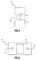
- FIG. 3is a side view of the inter-spinous spacer of the present invention as shown in FIG. 1 ;
- FIG. 4is a front view of the inter-spinous spacer of the present invention as shown in FIG. 1 ;
- FIG. 5is a top view of the inter-spinous spacer according to the present invention as shown in FIG. 1 ;
- FIG. 6is a cross-sectional view of the inter-spinous spacer of the present invention as taken through lines A-A of FIG. 5 ;
- FIG. 7is a perspective view illustrating the inter-spinous spacer shown in FIG. 1 with fusion-promoting materials disposed within an inner lumen according to one aspect of the present invention
- FIG. 8is a perspective view of an inter-spinous spacer according to a second embodiment of the present.
- FIG. 9is a side view of the inter-spinous spacer according to the present invention as shown in FIG. 8 ;
- FIG. 10is an end view of the inter-spinous spacer according to the present in invention as shown in FIGS. 8-9 ;
- FIG. 11is a perspective view of an inter-spinous spacer according to a third embodiment of the present invention in use affixed to a superior spinous process of a human spine;
- FIG. 12is a frontal view of the inter-spinous spacer according to the present in invention as shown in FIG. 11 , in place in between the two spinous processes;
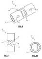
- FIG. 13is a side view of the inter-spinous spacer according to the present in invention as shown in FIG. 11 , in place in between the two spinous processes;
- FIG. 14is a side view of the inter-spinous spacer according to the present in invention as shown in FIG. 11 , in place in between the two spinous processes with fusion inducing material packed inside;
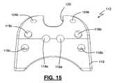
- FIG. 15is a front view of the inter-spinous spacer according the present invention as shown in FIG. 11 ;
- FIG. 16is a top view of an inter-spinous spacer according the present invention as shown in FIG. 11 ;
- FIG. 17is a back side view of an inter-spinous spacer according the present invention as shown in FIG. 11 ;
- FIG. 18is bottom view of an inter-spinous spacer according the present invention as shown in FIG. 11 ;
- FIG. 19is a side view of an inter-spinous spacer according the present invention as shown in FIG. 11 ;
- FIG. 20is perspective view of an inter-spinous spacer according the present invention as shown in FIG. 11 including visualization markers;
- FIGS. 21-23illustrate an exemplary insertion tool in use with the inter-spinous spacer of FIG. 11 , according to one embodiment of the present invention
- FIGS. 24-27illustrate an exemplary sizer tool for use when implanting the inter-spinous spacer as shown in FIG. 11 ; according one embodiment of the present invention
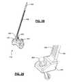
- FIGS. 28-29illustrate an alternate attachment device for use with the inter-spinous spacer shown in FIG. 11 according to an alternate embodiment of the present invention
- FIG. 30illustrates a posterior fluoroscopy view taken during implantation of the inter-spinous spacer of FIG. 11 demonstrating the alignment of markers (including the formation of a “T”) to aid in placement;
- FIG. 31illustrates a lateral fluoroscopy view taken during implantation of the inter-spinous spacer of FIG. 11 demonstrating the position of markers (including the formation of a backwards “L”) to aid in placement.
- FIG. 1illustrates a perspective view of a spinous process spacer 10 of the present invention in use between two spinous processes in a human spine.
- the spacer assembly 10includes a spacer 12 , a primary spinous process tether 14 , and two side tethers 15 (only one of which is shown in FIG. 1 ).
- the spacer 12as illustrated in FIGS. 2-6 , is generally cylindrical and includes a main chamber 16 , a pair of insertion tool apertures 18 , a fusion notch 20 , and a pair of tether lumens 22 .
- the spacer 12is (according to a preferred embodiment) coupled to only the superior spinous process such that the spacer 12 , with no coupling to the inferior spinous process.
- Thisis accomplished, but way of example only, by securing the primary spinous process tether 14 to the superior spinous process (as a first step of affixation), followed by passing one side tether 15 through each of the tether lumens 22 , in between the superior spinous process and the primary spinous process tether 14 , and finally tightening each side tether 15 until the spacer 12 is generally transverse to the longitudinal axis of the spine.
- the spacer 12may be of bone or non-bone construction.
- the bone embodimentinvolves manufacturing the spacer 12 from a suitable allograft, including but not limited to clavicle, rib, humerus, radius, ulna, metacarpal, phalanx, femur, tibia, fibula, or metatarsal bone.
- the non-bone embodimentinvolves manufacturing the spacer 12 from suitable non-bone materials, including but not limited to polyaryletherketone (PEEK) and polyaryletherketoneketone (PEKK). In either event, the spacer 12 is designed to fuse to the superior spinous process over time, resulting in what is called “hemi-fusion” in that the spacer 12 will be fused to only one spinous process.
- PEEKpolyaryletherketone
- PEKKpolyaryletherketoneketone
- Thismay be augmented by disposing any number of suitable fusion-inducing materials within the spacer 12 , including but not limited to BMP1, 2, 3, 4, 5, 6, 7, 8, 9, 10, 11, 12, 13, 14 . . . n, demineralized bone matrix, allograft cancellous bone, autograft bone, hydroxy appetite, coral and/or other highly porous substance.
- suitable fusion-inducing materialsincluding but not limited to BMP1, 2, 3, 4, 5, 6, 7, 8, 9, 10, 11, 12, 13, 14 . . . n, demineralized bone matrix, allograft cancellous bone, autograft bone, hydroxy appetite, coral and/or other highly porous substance.
- the spacer 12may also be coupled to only the inferior spinous process without departing from the scope of the present invention.
- the spacer 12once positioned, serves to distract the inter spinous process space, which advantageously restores foraminal height in stenotic patients and may also indirectly decompress the intervertebral space.
- the main chamber 16extends through the lateral sides of the spacer 12 .
- the main chamber 16may be provided in any of a variety of suitable shapes in addition to the generally cylindrical shape shown, including but not limited to a generally oblong, triangular, rectangular shape and/or combinations thereof.
- the main chamber 16may be dimensioned to receive fusion inducing materials 32 , as best illustrated in FIG. 7 .
- fusion inducing materialsmay include, but are not necessarily limited to BMP1, 2, 3, 4, 5, 6, 7, 8, 9, 10, 11, 12, 13, 14 . . . n, demineralized bone matrix, allograft cancellous bone, autograft bone, hydroxy appetite, coral and/or other highly porous substance.
- the fusion inducing materialsmay be packed into main chamber 16 before and/or after fixing spacer 10 to the spinous process.
- the pair of insertion tool apertures 18may be located on either the posterior or anterior side of the spacer 12 and extend a portion of the way through the spacer 12 .
- the fusion notch 20includes a slot or indent to receive a portion of an upper spinous process or other vertebral feature to enhance fusion.
- the notch 20may be located generally on the top surface towards the middle portion of the spacer 12 .
- the notch 20helps center the spacer 12 relative to the superior spinous process.
- the spacer 12may be provided with a second notch 21 opposite the fusion notch 20 .
- the second notch 21is capable of resting on the inferior spinous process during use, which may assist in maintaining the spacer 12 in a fully centered position relative to the inferior spinous process.
- the fusion notch 20may be further provided with slots 23 extending into the main chamber 16 .
- these slots 23will establish direct communication between the fusion-inducing compounds provided within the main chamber 16 and the lower aspect of the superior spinous process, which advantageously augments the ability of the spacer 12 to fuse to the superior spinous process (particularly if the spacer 12 is constructed of non-bone materials).
- the tether lumens 22each extend at an angle through the top surface of the spacer 12 and into the main chamber 16 .
- Each tether lumen 22may be provided in any of a variety of suitable shapes in addition to the cylindrical shape shown, including but not limited to oblong, triangular, rectangular and/or any combination thereof.
- the tethers 14 , 15may comprise any number of suitable materials and configurations, including but not limited to wire, cable, suture (permanent and/or bioresorbable), allograft tissue and/or other single or multi-filament member.
- Suture threadmay include any number of components capable of attaching to a spinous process, including but not limited to ordinary suture threads known to and used by those skilled in the art of wound closure. Suture thread may be of any length necessary to effectively fuse the spacer 12 to the particular spinous process.
- the spacer 12may be constructed of allograft bone and formed in a generally cylindrical shape.
- the spacer 12 of the present inventionmay be provided in any number of suitable shapes and sizes depending upon a particular patient and the shape and strength characteristics given the variation from cadaver to cadaver.
- the spacer 12may be dimensioned for use in the cervical and/or lumbar spine without departing from the scope of the present invention.
- the spacer 12may be dimensioned, by way of example only, having a length ranging between 6-20 mm and a height ranging between 20-25 mm.
- the spacer 12When constructed from allograft, the spacer 12 may be manufactured according to the following exemplary method.
- a belt sandermay first be used to reduce any high spots or imperfections to standardize the shape of the bone. Cut the allograft bone to length using the band saw. Remove the cancellous material from the inner canal to create the main chamber 16 . Using calipers, measure the struts and create a size distribution of spacers 12 . Machine the insertion tool apertures 18 . Set-up a standard vice for holding the implant across its width on the mill. Use a 3/32′′ ball end mill to create the insertion tool apertures 18 (same as cervical allograft implant). Insert the spacer 12 into the vice and tighten.
- Spacer 112includes a posterior side 113 , anterior side 114 , lateral sides 115 , a main chamber 116 , and a fusion notch 120 .
- Spacer 112is further provided with a plurality of apertures including, but not necessarily limited to, three pairs of insertion tool apertures 118 a , 118 b , and 118 c , tether lumens 122 , and secondary fusion apertures 124 b.
- FIGS. 12-14depict spacer 112 in use in the inter spinous process space of a patient.
- Spacer 112is designed to fit between a superior spinous process and an inferior spinous process and may be dimensioned in any number of suitable shapes and sizes to accomplish this.
- the spacer 112may be positioned in any of the cervical, thoracic, and/or lumbar spine and sizes may vary accordingly.
- spacer 112When in position, a properly sized spacer 112 distracts the inter spinous process space, restoring the foraminal height in stenotic patients and indirectly decompresses the intervertebral space.
- spacer 112may be dimensioned having a length ranging between 6-20 mm and a height ranging between 20-25 mm.
- Spacer 112is preferably constructed of non-bone material.
- Suitable non-bone materialsmay include, but are not necessarily limited, to polyaryletherketone (PEEK) and polyaryletherketoneketone (PEKK). Numerous advantages may be gained by constructing spacer 112 out of materials such as PEEK and PEKK.
- the stiffness properties of PEEK and PEKKclosely match that of bone. This reduces substantially the likelihood that the spinous process will remodel around spacer 112 causing a re-narrowing of the foraminal height and potentially resulting in revision surgeries.
- PEEK and PEKKare also substantially radiolucent which allows for improved post operative visualization of fusion between the implant and the superior spinous process.
- spacer 112may include fusion apertures only along the top (and potentially posterior side 113 ) such that fusion occurs only between the superior spinous process and spacer 112 . In this manner, extension is limited without disadvantageously limiting flexion as well.
- Main chamber 116extends through the lateral sides 115 of the spacer 112 .
- Main chamber 116may be provided in any of a variety of suitable shapes in addition to the generally cylindrical shape shown, including but not limited to a generally oblong, triangular, rectangular shape and/or combinations thereof.
- Main chamber 116may be dimensioned to receive fusion inducing materials 32 , as best illustrated in FIG. 14 .
- fusion inducing materialsmay include, but are not necessarily limited to BMP1, 2, 3, 4, 5, 6, 7, 8, 9, 10, 11, 12, 13, 14 . . . n, demineralized bone matrix, allograft cancellous bone, autograft bone, hydroxy appetite, coral and/or other highly porous substance.
- the fusion inducing materials 32may be packed into main chamber 16 before and/or after fixing spacer 10 to the spinous process.
- the fusion inducing material 32 packed within main chamber 16may communicate openly with the superior spinous process through any of the insertion tool apertures 118 a , 118 b , 118 c , fusion apertures 124 , and/or tether apertures 122 . Through this communication, fusion may occur from the superior spinous process into the main chamber 116 , permanently fixing spacer 112 in position.
- FIG. 16is a view of the top of spacer 112 .
- Fusion notch 120may be located generally on the top surface towards the middle portion of the spacer 112 .
- Fusion notch 120generally comprises a slot or indent dimensioned to receive an inferior portion of a superior spinous process.
- the notch 120helps center the spacer 112 relative to the superior spinous process and may assist in limiting side-to-side motion of spacer 112 prior to fusion.
- Fusion notch 120includes main fusion aperture 124 a .
- Main fusion aperture 124 aextends into main chamber 116 and is the main avenue for fusion between main chamber 116 and the superior spinous process.
- Secondary fusion apertures 124 bmay be located along the top of spacer 112 near the four corners of fusion notch 120 and extend into main chamber 116 . Secondary fusion apertures 124 b may provide additional routes for fusion to the superior spinous process. Tether apertures 122 may be located along the top center of spacer 112 near either side of fusion notch 120 . Tether apertures 122 are dimensioned to receive tethers 14 , 15 to temporarily fix spacer 112 in position until fusion to the superior spinous process occurs, permanently fixing spacer 112 in place.
- Main fusion aperture 124 asecondary fusion apertures 124 b , and tether apertures 122 may each be provided in any of a variety of shapes in addition to the generally circular shapes shown, including but not necessarily limited to, generally square, rectangular, oblong, triangular, and/or any combination thereof.
- FIG. 15illustrates the posterior side 113 of spacer 112 .
- the posterior side 113may include 3 separate pairs of insertion tool apertures 118 a , 118 b , and 118 c .
- having three pairs of insertion aperturesallow different insertion approaches to be utilized without needing to make available separate tools and/or spacers with alternate aperture configurations.
- Insertion tool aperturesextend into main chamber 116 and may serve as additional fusion routes after insertion, this may further solidify and strengthen the fusion between the superior spinous process and spacer 112 .
- FIG. 17illustrates the anterior side 114 of spacer 112 and FIG. 18 illustrates the bottom of the spacer.
- the anterior side 114is preferably free of any apertures (except, secondary fusion apertures 124 b may be located near the top of spacer 112 on the anterior side).
- the anterior side 114faces the spinal canal. Bone growth along the anterior side could potentially interfere with the spinal canal and the delicate neural tissue located inside, which could result in pain and/or further surgery for the patient.
- the lack of communication to main chamber 116 caused by the absence of apertures on the anterior side 114advantageously prevents bone growth in the area.
- the bottom of spacer 112is also aperture free and does not communicate with main chamber 116 .
- the bottom of spacer 112may preferably have a concave surface such that the distance from top to bottom of spacer 112 is greater neareast the lateral sides 115 and lesser near the center. The concave bottom may rest along the inferior spinous process and helps maintain spacer 112 in a centered position relative to the inferior spinous process.
- FIG. 19illustrates again a lateral side 115 with main chamber 116 extending therethrough.
- spacer 112may include at least one marker.
- spacer 112includes a top marker 126 and two side markers 128 .
- Markers 126 , 128may be comprised of biocompatible radio-opaque material, such as for example only, titanium (or other metals or polymers).
- Marker 126may be positioned along the center of spacer 112 within fusion notch 120 .
- marker 126extends through spacer 112 down to the bottom surface.
- Markers 128may be located in the lateral sides below main chamber 116 . During and after placement of the spacer 112 , markers 126 and 128 may be utilized to correctly orient spacer 112 .
- the marker 126 situated in the center and extending from fusion notch 120 to the bottom surfaceshould make a line between the superior spinous process and the inferior spinous process viewable on the fluoroscopy screen when the spacer 112 is properly positioned, as pictured in FIG. 30 .
- Markers 128should be positioned on each side of the superior and inferior spinous process in the inter spinous process space. Drawing an imaginary line between markers 128 and connecting that line to an imaginary line extending marker 126 to it should form an upside down “T” if properly positioned.
- Marker 126runs along the posterior side 113 of spacer 112 .
- markers 128may be positioned in the lateral side 115 near the posterior side 113 .
- one marker 128is positioned near the posterior side 113 and one marker 128 may be positioned near the anterior side 114 .
- the position of the markers 126 and 128may be viewed in relation to the posterior end of the spinous processes and the more anterior vertebral elements to ensure spacer 112 is neither too far anteriorly nor to far posoteriorly. Drawing an imaginary line between markers 128 and connecting that line to an imaginary line extending marker 126 to it should form a backwards “L” if properly positioned, as pictured in FIG. 31 .
- the spinal apparatus 10 of the present inventionmay be introduced into a spinal target site through the use of any of a variety of suitable instruments having the capability to releasably engage the spacer 12 , 112 .
- the insertion toolpermits quick, direct, accurate placement of the spacers 12 , 112 between an upper and lower spinous process.
- An exemplary insertion toolis shown and described in commonly owned U.S. Pat. No. 6,923,814 entitled “System and Method for Cervical Fusion,” which is expressly incorporated by reference as if set forth fully herein.
- FIGS. 21-23depict an exemplary insertion tool 200 for use with spacers 12 , 112 .
- insertion tool 200includes a pair of prongs 204 dimensioned to engage insertion apertures 18 and 118 a , 118 b , 118 c such that spacer 12 , 112 becomes temporarily attached to the distal end 202 for insertion.
- Insertion apertures 118 aare aligned laterally in the center of spacer 112 such that spacer 112 and insertion tool 200 mate at approximately the center point of the spacer, as pictured in FIG. 22 . This configuration may be advantageous if approaching the inter spinous process space from a directly posterior approach.
- Insertion apertures 118 b and 118 care aligned vertically near opposite sides of spacer 112 , such that spacer 112 and insertion tool 200 mate at near the selected side, as illustrated in FIG. 23 (shown with tool 200 attached to insertion apertures 118 b ). This configuration may be advantageous if approaching from a more lateral direction.
- a clinicianIn order to use the spinal apparatus 10 of the present invention in a treatment of spinal stenosis, a clinician must first designate the appropriate spacer size 12 , 112 .
- a cliniciancan utilize the spinal apparatus 10 in either an open or minimally invasive spinal fusion procedure. In either type of procedure, a working channel would be created in a patient that reaches a targeted spinal level. After the creation of the working channel, the interspinous space would be prepared. After preparation a sizer instrument is used to determine the appropriate size of the spacer 12 , 112 .
- One exemplary sizer instrument 300is illustrated by way of example only in FIGS. 24-27 . Sizer instrument 300 includes a handle portion 302 and an implant portion 304 . Handle portion 302 may be configured in any variety of suitable shapes and sizes.
- Implant portion 304may be provided in a variety of sizes matching the various sizes of spacer 112 . As pictured, sizer implant may be proved in an asymmetrical shape where the side opposite the handle 302 has a lesser height than the side to which handle 302 is attached. This may allow the implant portion 304 to be rotated into position with minimal interference from the spinous process. Although it is not shown, it is conceived that spacer 112 may also be provided in this asymmetrical fashion.
- Preparation of the inter spinous process spaceincludes perforating the interspinous ligament between the superior and inferior spinous processes.
- the supraspinous ligamentmay preferably be left intact and distracted out of the way if necessary.
- a key part of the preparationincludes abrading the inferior portion of the superior spinous process where it will communicate with the fusion inducing materials 32 packed in the main chamber 16 , 116 . Abrading removes the hard cortical bone from the inferior surface of the superior spinous process and leaves bleeding bone which is better adapted for fusion. As new bone generates to heal the abraded portion it may grow into the main chamber 16 , 116 , fixing spacer 12 , 112 to the superior spinous process.
- the spacer 12 , 112is held in position with tethers 14 , 15 attached to the spinous process through tether lumen 22 , 122 .
- an alternate securing mechanismmay be used to fix spacer 12 , 112 in place.
- the alternate securing mechanismincludes a zip cable 400 and a pair of locking bases 402 , 404 .
- Base 402may be integral with cable 400 .
- Base 402is positioned on the top of spacer 12 , 112 next to the fusion notch 20 , 120 and fixed to the spacer 12 , 112 via tether apertures 22 , 122 .
- Base 402is positioned over tether aperture 22 , 122 and a locking pin 406 is inserted through the base into tether aperture 22 , 122 .
- the stepis repeated for base 404 on the opposite side of the fusion notch 20 , 120 .
- the zip cable 400may be wrapped around the superior spinous process and fed through the opposing base 404 . Teeth 408 on the cable 400 prevent cable 400 from loosening and thus holds the spacer 12 , 112 in place for fusion to occur.
- Any of a variety of suitable materialsmay be used to form the zip cable 400 , bases 402 , 404 , and locking pins 406 .
- the cable 400 and bases 402 , 404are comprised of nylon and the locking pins 406 are comprised of titanium.
- the spinal apparatus 10holds the vertebrae in a flexed position, preventing extension but advantageously allowing flexion.
Landscapes
- Health & Medical Sciences (AREA)
- Orthopedic Medicine & Surgery (AREA)
- Life Sciences & Earth Sciences (AREA)
- Neurology (AREA)
- Surgery (AREA)
- Heart & Thoracic Surgery (AREA)
- Engineering & Computer Science (AREA)
- Biomedical Technology (AREA)
- Nuclear Medicine, Radiotherapy & Molecular Imaging (AREA)
- Medical Informatics (AREA)
- Molecular Biology (AREA)
- Animal Behavior & Ethology (AREA)
- General Health & Medical Sciences (AREA)
- Public Health (AREA)
- Veterinary Medicine (AREA)
- Prostheses (AREA)
Abstract
Description
Claims (22)
Priority Applications (3)
| Application Number | Priority Date | Filing Date | Title |
|---|---|---|---|
| US11/540,318US8167915B2 (en) | 2005-09-28 | 2006-09-28 | Methods and apparatus for treating spinal stenosis |
| JP2007279595AJP2008100079A (en) | 2006-09-28 | 2007-09-28 | Method and apparatus for treating spinal stenosis |
| US13/461,771US20120296377A1 (en) | 2005-09-28 | 2012-05-01 | Methods and Apparatus for Treating Spinal Stenosis |
Applications Claiming Priority (2)
| Application Number | Priority Date | Filing Date | Title |
|---|---|---|---|
| US72206505P | 2005-09-28 | 2005-09-28 | |
| US11/540,318US8167915B2 (en) | 2005-09-28 | 2006-09-28 | Methods and apparatus for treating spinal stenosis |
Related Child Applications (1)
| Application Number | Title | Priority Date | Filing Date |
|---|---|---|---|
| US13/461,771ContinuationUS20120296377A1 (en) | 2005-09-28 | 2012-05-01 | Methods and Apparatus for Treating Spinal Stenosis |
Publications (2)
| Publication Number | Publication Date |
|---|---|
| US20070093825A1 US20070093825A1 (en) | 2007-04-26 |
| US8167915B2true US8167915B2 (en) | 2012-05-01 |
Family
ID=37986262
Family Applications (2)
| Application Number | Title | Priority Date | Filing Date |
|---|---|---|---|
| US11/540,318Active2029-09-15US8167915B2 (en) | 2005-09-28 | 2006-09-28 | Methods and apparatus for treating spinal stenosis |
| US13/461,771AbandonedUS20120296377A1 (en) | 2005-09-28 | 2012-05-01 | Methods and Apparatus for Treating Spinal Stenosis |
Family Applications After (1)
| Application Number | Title | Priority Date | Filing Date |
|---|---|---|---|
| US13/461,771AbandonedUS20120296377A1 (en) | 2005-09-28 | 2012-05-01 | Methods and Apparatus for Treating Spinal Stenosis |
Country Status (1)
| Country | Link |
|---|---|
| US (2) | US8167915B2 (en) |
Cited By (39)
| Publication number | Priority date | Publication date | Assignee | Title |
|---|---|---|---|---|
| US20080177306A1 (en)* | 2004-10-25 | 2008-07-24 | Lanx, Inc. | Spinal implants and methods |
| US20100241167A1 (en)* | 2007-01-11 | 2010-09-23 | Lanx, Inc. | Spinous process implants and associated methods |
| US20110166600A1 (en)* | 2007-01-11 | 2011-07-07 | Lanx, Inc. | Interspinsous implants and methods |
| US20120089184A1 (en)* | 2010-10-08 | 2012-04-12 | Chung-Chun Yeh | Device for tightly gripping on the spinous process of the spine |
| US20120310282A1 (en)* | 2008-07-05 | 2012-12-06 | Abdou M Samy | Device and method for the prevention of multi-level vertebral extension |
| US20130158604A1 (en)* | 2011-06-17 | 2013-06-20 | Bryan Okamoto | Expandable Interspinous Device |
| US20130190879A1 (en)* | 2009-07-24 | 2013-07-25 | Zyga Technology, Inc. | Methods for facet joint treatment |
| US8551175B1 (en)* | 2008-03-27 | 2013-10-08 | Spinelogik, Inc. | Method and apparatus for retaining a fusion member while delivering the fusion member between two vertebral bodies |
| US20140163686A1 (en)* | 2009-09-11 | 2014-06-12 | DePuy Synthes Products, LLC | Minimally invasive intervertebral staple distraction devices |
| US8876869B1 (en)* | 2009-06-19 | 2014-11-04 | Nuvasive, Inc. | Polyaxial bone screw assembly |
| US9028549B1 (en)* | 2008-03-27 | 2015-05-12 | Spinelogik, Inc. | Intervertebral fusion device and method of use |
| US9060813B1 (en) | 2008-02-29 | 2015-06-23 | Nuvasive, Inc. | Surgical fixation system and related methods |
| US9387013B1 (en) | 2011-03-01 | 2016-07-12 | Nuvasive, Inc. | Posterior cervical fixation system |
| US9427324B1 (en) | 2010-02-22 | 2016-08-30 | Spinelogik, Inc. | Intervertebral fusion device and method of use |
| US9615933B2 (en) | 2009-09-15 | 2017-04-11 | DePuy Synthes Products, Inc. | Expandable ring intervertebral fusion device |
| US9675386B2 (en) | 2013-03-11 | 2017-06-13 | K2M, Inc. | Flexible fastening system |
| US9795421B2 (en) | 2015-07-07 | 2017-10-24 | K2M, Inc. | Spinal construct with flexible member |
| US9861400B2 (en) | 2007-01-11 | 2018-01-09 | Zimmer Biomet Spine, Inc. | Spinous process implants and associated methods |
| US10321833B2 (en) | 2016-10-05 | 2019-06-18 | Innovative Surgical Solutions. | Neural locating method |
| US10376209B2 (en) | 2013-09-20 | 2019-08-13 | Innovative Surgical Solutions, Llc | Neural locating method |
| US10376208B2 (en) | 2013-09-20 | 2019-08-13 | Innovative Surgical Solutions, Llc | Nerve mapping system |
| US10449002B2 (en) | 2013-09-20 | 2019-10-22 | Innovative Surgical Solutions, Llc | Method of mapping a nerve |
| US10478096B2 (en) | 2013-08-13 | 2019-11-19 | Innovative Surgical Solutions. | Neural event detection |
| US10478097B2 (en) | 2013-08-13 | 2019-11-19 | Innovative Surgical Solutions | Neural event detection |
| US10543107B2 (en) | 2009-12-07 | 2020-01-28 | Samy Abdou | Devices and methods for minimally invasive spinal stabilization and instrumentation |
| US10548740B1 (en) | 2016-10-25 | 2020-02-04 | Samy Abdou | Devices and methods for vertebral bone realignment |
| US10575961B1 (en) | 2011-09-23 | 2020-03-03 | Samy Abdou | Spinal fixation devices and methods of use |
| US10695105B2 (en) | 2012-08-28 | 2020-06-30 | Samy Abdou | Spinal fixation devices and methods of use |
| US10857003B1 (en) | 2015-10-14 | 2020-12-08 | Samy Abdou | Devices and methods for vertebral stabilization |
| US10870002B2 (en) | 2018-10-12 | 2020-12-22 | DePuy Synthes Products, Inc. | Neuromuscular sensing device with multi-sensor array |
| US10869616B2 (en) | 2018-06-01 | 2020-12-22 | DePuy Synthes Products, Inc. | Neural event detection |
| US10918498B2 (en) | 2004-11-24 | 2021-02-16 | Samy Abdou | Devices and methods for inter-vertebral orthopedic device placement |
| US10973648B1 (en) | 2016-10-25 | 2021-04-13 | Samy Abdou | Devices and methods for vertebral bone realignment |
| US11006982B2 (en) | 2012-02-22 | 2021-05-18 | Samy Abdou | Spinous process fixation devices and methods of use |
| US11173040B2 (en) | 2012-10-22 | 2021-11-16 | Cogent Spine, LLC | Devices and methods for spinal stabilization and instrumentation |
| US11179248B2 (en) | 2018-10-02 | 2021-11-23 | Samy Abdou | Devices and methods for spinal implantation |
| US11399777B2 (en) | 2019-09-27 | 2022-08-02 | DePuy Synthes Products, Inc. | Intraoperative neural monitoring system and method |
| US11812923B2 (en) | 2011-10-07 | 2023-11-14 | Alan Villavicencio | Spinal fixation device |
| US12121269B2 (en) | 2016-10-11 | 2024-10-22 | K2M, Inc. | Spinal implant and methods of use thereof |
Families Citing this family (33)
| Publication number | Priority date | Publication date | Assignee | Title |
|---|---|---|---|---|
| US7862592B2 (en)* | 2005-12-06 | 2011-01-04 | Nuvasive, Inc. | Methods and apparatus for treating spinal stenosis |
| EP1968466A2 (en) | 2005-12-19 | 2008-09-17 | M. S. Abdou | Devices for inter-vertebral orthopedic device placement |
| US20080082172A1 (en)* | 2006-09-29 | 2008-04-03 | Jackson Roger P | Interspinous process spacer |
| US8382801B2 (en)* | 2007-01-11 | 2013-02-26 | Lanx, Inc. | Spinous process implants, instruments, and methods |
| WO2008106478A1 (en)* | 2007-02-27 | 2008-09-04 | Lanx, Llc | Compositions and methods for modification of target cells and to their uses thereof |
| WO2008151119A2 (en)* | 2007-06-01 | 2008-12-11 | Lanx, Llc | Compositions and methods for use of scar tissue in repair of weight bearing surfaces |
| US8070779B2 (en)* | 2007-06-04 | 2011-12-06 | K2M, Inc. | Percutaneous interspinous process device and method |
| WO2009013397A1 (en)* | 2007-07-25 | 2009-01-29 | Ros Guillen, Francisco | Vertebral fastening device for a system for correcting the abnormal curvatures of the rachis |
| WO2009105606A1 (en)* | 2008-02-21 | 2009-08-27 | Lanx, Llc | Compositions and methods for use of scar tissue in repair of weight bearing surfaces |
| TW200938157A (en)* | 2008-03-11 | 2009-09-16 | Fong-Ying Chuang | Interspinous spine fixing device |
| US8343190B1 (en) | 2008-03-26 | 2013-01-01 | Nuvasive, Inc. | Systems and methods for spinous process fixation |
| US9149319B2 (en)* | 2008-09-23 | 2015-10-06 | Lanx, Llc | Methods and compositions for stabilization of a vertebra |
| US8292923B1 (en)* | 2008-10-13 | 2012-10-23 | Nuvasive, Inc. | Systems and methods for treating spinal stenosis |
| WO2010068829A2 (en)* | 2008-12-12 | 2010-06-17 | Spinefrontier, Inc. | Improved spinous process fixation implant |
| US8231626B2 (en)* | 2009-05-12 | 2012-07-31 | Synthes Usa, Llc | Self-retaining cable tie |
| US9901455B2 (en) | 2009-11-25 | 2018-02-27 | Nathan C. Moskowitz | Total artificial spino-laminar prosthetic replacement |
| GB0922614D0 (en)* | 2009-12-23 | 2010-02-10 | Butterfield Forbes | Device |
| US20110160772A1 (en)* | 2009-12-28 | 2011-06-30 | Arcenio Gregory B | Systems and methods for performing spinal fusion |
| US20110307010A1 (en)* | 2010-02-18 | 2011-12-15 | Osprey Biomedical Corp. | Interspinous device and method of implanting |
| US8758412B2 (en)* | 2010-09-20 | 2014-06-24 | Pachyderm Medical, L.L.C. | Integrated IPD devices, methods, and systems |
| US8702756B2 (en) | 2010-09-23 | 2014-04-22 | Alphatec Spine, Inc. | Clamping interspinous spacer apparatus and methods of use |
| US8821547B2 (en) | 2010-11-01 | 2014-09-02 | Warsaw Orthopedic, Inc. | Spinous process implant with a post and an enlarged boss |
| US9084644B2 (en) | 2011-02-02 | 2015-07-21 | DePuy Synthes Products, Inc. | Bone fixation assembly |
| US8496689B2 (en)* | 2011-02-23 | 2013-07-30 | Farzad Massoudi | Spinal implant device with fusion cage and fixation plates and method of implanting |
| US9498560B2 (en)* | 2011-03-04 | 2016-11-22 | Spinefrontier, Inc | Interspinous spacer implant |
| US8425560B2 (en) | 2011-03-09 | 2013-04-23 | Farzad Massoudi | Spinal implant device with fixation plates and lag screws and method of implanting |
| USD757943S1 (en) | 2011-07-14 | 2016-05-31 | Nuvasive, Inc. | Spinous process plate |
| US8882805B1 (en) | 2011-08-02 | 2014-11-11 | Lawrence Maccree | Spinal fixation system |
| US10448977B1 (en) | 2012-03-31 | 2019-10-22 | Ali H. MESIWALA | Interspinous device and related methods |
| TWI466653B (en)* | 2012-04-10 | 2015-01-01 | Paonan Biotech Co Ltd | A multi - segment spine spinous process |
| US9603646B2 (en) | 2014-05-30 | 2017-03-28 | DePuy Synthes Products, Inc. | Bone fixation assembly |
| US9717541B2 (en) | 2015-04-13 | 2017-08-01 | DePuy Synthes Products, Inc. | Lamina implants and methods for spinal decompression |
| US11998457B2 (en)* | 2020-05-05 | 2024-06-04 | Corelink, Llc | Implant trial with radiographically visible indicium |
Citations (124)
| Publication number | Priority date | Publication date | Assignee | Title |
|---|---|---|---|---|
| US2677369A (en) | 1952-03-26 | 1954-05-04 | Fred L Knowles | Apparatus for treatment of the spinal column |
| US3426364A (en) | 1966-08-25 | 1969-02-11 | Colorado State Univ Research F | Prosthetic appliance for replacing one or more natural vertebrae |
| US3648691A (en) | 1970-02-24 | 1972-03-14 | Univ Colorado State Res Found | Method of applying vertebral appliance |
| US3875595A (en) | 1974-04-15 | 1975-04-08 | Edward C Froning | Intervertebral disc prosthesis and instruments for locating same |
| US4369769A (en) | 1980-06-13 | 1983-01-25 | Edwards Charles C | Spinal fixation device and method |
| US4554914A (en) | 1983-10-04 | 1985-11-26 | Kapp John P | Prosthetic vertebral body |
| US4570618A (en) | 1983-11-23 | 1986-02-18 | Henry Ford Hospital | Intervertebral body wire stabilization |
| US4599086A (en) | 1985-06-07 | 1986-07-08 | Doty James R | Spine stabilization device and method |
| US4604995A (en) | 1984-03-30 | 1986-08-12 | Stephens David C | Spinal stabilizer |
| US4611582A (en) | 1983-12-27 | 1986-09-16 | Wisconsin Alumni Research Foundation | Vertebral clamp |
| US4643178A (en) | 1984-04-23 | 1987-02-17 | Fabco Medical Products, Inc. | Surgical wire and method for the use thereof |
| US4685447A (en) | 1985-03-25 | 1987-08-11 | Pmt Corporation | Tissue expander system |
| US4696290A (en) | 1983-12-16 | 1987-09-29 | Acromed Corporation | Apparatus for straightening spinal columns |
| US4728329A (en) | 1985-05-03 | 1988-03-01 | Sulzer Brothers Ltd. | Prosthetic band |
| US4795466A (en) | 1986-03-07 | 1989-01-03 | Sulzer Brothers Limited | Artificial crucial ligament for a knee joint |
| US4805602A (en) | 1986-11-03 | 1989-02-21 | Danninger Medical Technology | Transpedicular screw and rod system |
| US4913134A (en) | 1987-07-24 | 1990-04-03 | Biotechnology, Inc. | Spinal fixation system |
| US4917700A (en) | 1988-08-01 | 1990-04-17 | Zimmer, Inc. | Prosthetic ligament |
| US4946378A (en) | 1987-11-24 | 1990-08-07 | Asahi Kogaku Kogyo Kabushiki Kaisha | Artificial intervertebral disc |
| US4969888A (en) | 1989-02-09 | 1990-11-13 | Arie Scholten | Surgical protocol for fixation of osteoporotic bone using inflatable device |
| US5011484A (en) | 1987-11-16 | 1991-04-30 | Breard Francis H | Surgical implant for restricting the relative movement of vertebrae |
| US5030220A (en) | 1990-03-29 | 1991-07-09 | Advanced Spine Fixation Systems Incorporated | Spine fixation system |
| US5035716A (en) | 1987-12-07 | 1991-07-30 | Downey Ernest L | Replacement disc |
| US5047055A (en) | 1990-12-21 | 1991-09-10 | Pfizer Hospital Products Group, Inc. | Hydrogel intervertebral disc nucleus |
| US5059194A (en) | 1990-02-12 | 1991-10-22 | Michelson Gary K | Cervical distractor |
| US5084049A (en) | 1989-02-08 | 1992-01-28 | Acromed Corporation | Transverse connector for spinal column corrective devices |
| US5092893A (en) | 1990-09-04 | 1992-03-03 | Smith Thomas E | Human orthopedic vertebra implant |
| US5092866A (en) | 1989-02-03 | 1992-03-03 | Breard Francis H | Flexible inter-vertebral stabilizer as well as process and apparatus for determining or verifying its tension before installation on the spinal column |
| US5123926A (en) | 1991-02-22 | 1992-06-23 | Madhavan Pisharodi | Artificial spinal prosthesis |
| US5167662A (en) | 1992-01-24 | 1992-12-01 | Zimmer, Inc. | Temporary clamp and inserter for a posterior midline spinal clamp |
| US5180381A (en) | 1991-09-24 | 1993-01-19 | Aust Gilbert M | Anterior lumbar/cervical bicortical compression plate |
| US5180393A (en) | 1990-09-21 | 1993-01-19 | Polyclinique De Bourgogne & Les Hortensiad | Artificial ligament for the spine |
| US5192327A (en) | 1991-03-22 | 1993-03-09 | Brantigan John W | Surgical prosthetic implant for vertebrae |
| US5282863A (en) | 1985-06-10 | 1994-02-01 | Charles V. Burton | Flexible stabilization system for a vertebral column |
| US5290312A (en) | 1991-09-03 | 1994-03-01 | Alphatec | Artificial vertebral body |
| US5304178A (en) | 1992-05-29 | 1994-04-19 | Acromed Corporation | Sublaminar wire |
| US5306309A (en) | 1992-05-04 | 1994-04-26 | Calcitek, Inc. | Spinal disk implant and implantation kit |
| US5352225A (en) | 1993-01-14 | 1994-10-04 | Yuan Hansen A | Dual-tier spinal clamp locking and retrieving system |
| US5375823A (en) | 1992-06-25 | 1994-12-27 | Societe Psi | Application of an improved damper to an intervertebral stabilization device |
| US5387213A (en) | 1991-02-05 | 1995-02-07 | Safir S.A.R.L. | Osseous surgical implant particularly for an intervertebral stabilizer |
| US5390683A (en) | 1991-02-22 | 1995-02-21 | Pisharodi; Madhavan | Spinal implantation methods utilizing a middle expandable implant |
| US5395372A (en) | 1993-09-07 | 1995-03-07 | Danek Medical, Inc. | Spinal strut graft holding staple |
| US5415661A (en) | 1993-03-24 | 1995-05-16 | University Of Miami | Implantable spinal assist device |
| US5443514A (en) | 1993-10-01 | 1995-08-22 | Acromed Corporation | Method for using spinal implants |
| US5458643A (en) | 1991-03-29 | 1995-10-17 | Kyocera Corporation | Artificial intervertebral disc |
| US5458638A (en) | 1989-07-06 | 1995-10-17 | Spine-Tech, Inc. | Non-threaded spinal implant |
| US5458641A (en) | 1993-09-08 | 1995-10-17 | Ramirez Jimenez; Juan J. | Vertebral body prosthesis |
| US5470333A (en) | 1993-03-11 | 1995-11-28 | Danek Medical, Inc. | System for stabilizing the cervical and the lumbar region of the spine |
| US5480401A (en) | 1993-02-17 | 1996-01-02 | Psi | Extra-discal inter-vertebral prosthesis for controlling the variations of the inter-vertebral distance by means of a double damper |
| US5496318A (en) | 1993-01-08 | 1996-03-05 | Advanced Spine Fixation Systems, Inc. | Interspinous segmental spine fixation device |
| US5505732A (en) | 1988-06-13 | 1996-04-09 | Michelson; Gary K. | Apparatus and method of inserting spinal implants |
| US5514180A (en) | 1994-01-14 | 1996-05-07 | Heggeness; Michael H. | Prosthetic intervertebral devices |
| US5534029A (en) | 1992-12-14 | 1996-07-09 | Yumiko Shima | Articulated vertebral body spacer |
| US5534028A (en) | 1993-04-20 | 1996-07-09 | Howmedica, Inc. | Hydrogel intervertebral disc nucleus with diminished lateral bulging |
| US5540688A (en) | 1991-05-30 | 1996-07-30 | Societe "Psi" | Intervertebral stabilization device incorporating dampers |
| US5540689A (en) | 1990-05-22 | 1996-07-30 | Sanders; Albert E. | Apparatus for securing a rod adjacent to a bone |
| US5549679A (en) | 1994-05-20 | 1996-08-27 | Kuslich; Stephen D. | Expandable fabric implant for stabilizing the spinal motion segment |
| US5562736A (en) | 1994-10-17 | 1996-10-08 | Raymedica, Inc. | Method for surgical implantation of a prosthetic spinal disc nucleus |
| US5593409A (en) | 1988-06-13 | 1997-01-14 | Sofamor Danek Group, Inc. | Interbody spinal fusion implants |
| US5609634A (en) | 1992-07-07 | 1997-03-11 | Voydeville; Gilles | Intervertebral prosthesis making possible rotatory stabilization and flexion/extension stabilization |
| US5645599A (en) | 1994-07-26 | 1997-07-08 | Fixano | Interspinal vertebral implant |
| US5645597A (en) | 1995-12-29 | 1997-07-08 | Krapiva; Pavel I. | Disc replacement method and apparatus |
| US5653761A (en) | 1994-03-18 | 1997-08-05 | Pisharodi; Madhavan | Method of lumbar intervertebral disk stabilization |
| US5658286A (en) | 1996-02-05 | 1997-08-19 | Sava; Garard A. | Fabrication of implantable bone fixation elements |
| US5672175A (en) | 1993-08-27 | 1997-09-30 | Martin; Jean Raymond | Dynamic implanted spinal orthosis and operative procedure for fitting |
| US5674296A (en) | 1994-11-14 | 1997-10-07 | Spinal Dynamics Corporation | Human spinal disc prosthesis |
| US5674295A (en) | 1994-10-17 | 1997-10-07 | Raymedica, Inc. | Prosthetic spinal disc nucleus |
| US5676702A (en) | 1994-12-16 | 1997-10-14 | Tornier S.A. | Elastic disc prosthesis |
| US5702455A (en) | 1996-07-03 | 1997-12-30 | Saggar; Rahul | Expandable prosthesis for spinal fusion |
| US5725582A (en) | 1992-08-19 | 1998-03-10 | Surgicraft Limited | Surgical implants |
| US5766252A (en) | 1995-01-24 | 1998-06-16 | Osteonics Corp. | Interbody spinal prosthetic implant and method |
| US5814046A (en) | 1992-11-13 | 1998-09-29 | Sofamor S.N.C. | Pedicular screw and posterior spinal instrumentation |
| US5824098A (en) | 1994-10-24 | 1998-10-20 | Stein; Daniel | Patello-femoral joint replacement device and method |
| US5836948A (en)* | 1997-01-02 | 1998-11-17 | Saint Francis Medical Technologies, Llc | Spine distraction implant and method |
| US5860977A (en) | 1997-01-02 | 1999-01-19 | Saint Francis Medical Technologies, Llc | Spine distraction implant and method |
| US5885299A (en) | 1994-09-15 | 1999-03-23 | Surgical Dynamics, Inc. | Apparatus and method for implant insertion |
| US5888224A (en) | 1993-09-21 | 1999-03-30 | Synthesis (U.S.A.) | Implant for intervertebral space |
| US5888226A (en) | 1997-11-12 | 1999-03-30 | Rogozinski; Chaim | Intervertebral prosthetic disc |
| US5904686A (en) | 1996-07-01 | 1999-05-18 | Zucherman; James F. | Apparatus and method for preparing a site for an interbody fusion implant |
| US5976186A (en) | 1994-09-08 | 1999-11-02 | Stryker Technologies Corporation | Hydrogel intervertebral disc nucleus |
| US6022376A (en) | 1997-06-06 | 2000-02-08 | Raymedica, Inc. | Percutaneous prosthetic spinal disc nucleus and method of manufacture |
| US6048342A (en) | 1997-01-02 | 2000-04-11 | St. Francis Medical Technologies, Inc. | Spine distraction implant |
| US6068630A (en) | 1997-01-02 | 2000-05-30 | St. Francis Medical Technologies, Inc. | Spine distraction implant |
| US6113639A (en) | 1999-03-23 | 2000-09-05 | Raymedica, Inc. | Trial implant and trial implant kit for evaluating an intradiscal space |
| US6156038A (en) | 1997-01-02 | 2000-12-05 | St. Francis Medical Technologies, Inc. | Spine distraction implant and method |
| US6234705B1 (en) | 1999-04-06 | 2001-05-22 | Synthes (Usa) | Transconnector for coupling spinal rods |
| US20010020188A1 (en) | 1997-10-27 | 2001-09-06 | Tom Sander | Selective uptake of materials by bone implants |
| US6290700B1 (en) | 1997-07-31 | 2001-09-18 | Plus Endoprothetik Ag | Device for stiffening and/or correcting a vertebral column or such like |
| US6355038B1 (en) | 1998-09-25 | 2002-03-12 | Perumala Corporation | Multi-axis internal spinal fixation |
| US6402750B1 (en) | 2000-04-04 | 2002-06-11 | Spinlabs, Llc | Devices and methods for the treatment of spinal disorders |
| US6451019B1 (en) | 1998-10-20 | 2002-09-17 | St. Francis Medical Technologies, Inc. | Supplemental spine fixation device and method |
| US6514256B2 (en) | 1997-01-02 | 2003-02-04 | St. Francis Medical Technologies, Inc. | Spine distraction implant and method |
| US6514255B1 (en) | 2000-02-25 | 2003-02-04 | Bret Ferree | Sublaminar spinal fixation apparatus |
| US20030040746A1 (en) | 2001-07-20 | 2003-02-27 | Mitchell Margaret E. | Spinal stabilization system and method |
| US20030045935A1 (en) | 2001-02-28 | 2003-03-06 | Angelucci Christopher M. | Laminoplasty implants and methods of use |
| US20030060823A1 (en) | 2001-09-24 | 2003-03-27 | Bryan Donald W. | Pedicle screw spinal fixation device |
| US6558387B2 (en) | 2001-01-30 | 2003-05-06 | Fastemetix, Llc | Porous interbody fusion device having integrated polyaxial locking interference screws |
| US6626944B1 (en) | 1998-02-20 | 2003-09-30 | Jean Taylor | Interspinous prosthesis |
| US6652527B2 (en) | 1998-10-20 | 2003-11-25 | St. Francis Medical Technologies, Inc. | Supplemental spine fixation device and method |
| US6652534B2 (en) | 1998-10-20 | 2003-11-25 | St. Francis Medical Technologies, Inc. | Apparatus and method for determining implant size |
| US6669697B1 (en) | 1998-09-25 | 2003-12-30 | Perumala Corporation | Self-retaining bolt for internal spinal stabilizers |
| US20040019356A1 (en)* | 2002-07-23 | 2004-01-29 | Robert Fraser | Surgical trial implant |
| US6695882B2 (en) | 1997-06-03 | 2004-02-24 | Sdgi Holdings, Inc. | Open intervertebral spacer |
| US6695842B2 (en) | 1997-10-27 | 2004-02-24 | St. Francis Medical Technologies, Inc. | Interspinous process distraction system and method with positionable wing and method |
| US6712819B2 (en) | 1998-10-20 | 2004-03-30 | St. Francis Medical Technologies, Inc. | Mating insertion instruments for spinal implants and methods of use |
| US6740090B1 (en) | 2000-02-16 | 2004-05-25 | Trans1 Inc. | Methods and apparatus for forming shaped axial bores through spinal vertebrae |
| US20040106995A1 (en) | 2000-07-12 | 2004-06-03 | Regis Le Couedic | Shock-absorbing intervertebral implant |
| US6761720B1 (en) | 1999-10-15 | 2004-07-13 | Spine Next | Intervertebral implant |
| US6796983B1 (en) | 1997-01-02 | 2004-09-28 | St. Francis Medical Technologies, Inc. | Spine distraction implant and method |
| US20050165398A1 (en) | 2004-01-26 | 2005-07-28 | Reiley Mark A. | Percutaneous spine distraction implant systems and methods |
| US20060085070A1 (en) | 2004-10-20 | 2006-04-20 | Vertiflex, Inc. | Systems and methods for posterior dynamic stabilization of the spine |
| US20060106381A1 (en)* | 2004-11-18 | 2006-05-18 | Ferree Bret A | Methods and apparatus for treating spinal stenosis |
| US20060235532A1 (en)* | 2003-01-20 | 2006-10-19 | Abbott Spine | Unit for treatment of the degeneration of an intervertebral disc |
| US20060241601A1 (en) | 2005-04-08 | 2006-10-26 | Trautwein Frank T | Interspinous vertebral and lumbosacral stabilization devices and methods of use |
| US20060247634A1 (en)* | 2005-05-02 | 2006-11-02 | Warner Kenneth D | Spinous Process Spacer Implant and Technique |
| US20060293662A1 (en)* | 2005-06-13 | 2006-12-28 | Boyer Michael L Ii | Spinous process spacer |
| US7172593B2 (en) | 2000-10-25 | 2007-02-06 | Sdgi Holdings, Inc. | Non-metallic implant devices and intra-operative methods for assembly and fixation |
| US20070032790A1 (en)* | 2005-08-05 | 2007-02-08 | Felix Aschmann | Apparatus for treating spinal stenosis |
| US20070043361A1 (en)* | 2005-02-17 | 2007-02-22 | Malandain Hugues F | Percutaneous spinal implants and methods |
| US20070073292A1 (en) | 2005-02-17 | 2007-03-29 | Kohm Andrew C | Percutaneous spinal implants and methods |
| US7201775B2 (en) | 2002-09-24 | 2007-04-10 | Bogomir Gorensek | Stabilizing device for intervertebral disc, and methods thereof |
| US20080015701A1 (en) | 2001-11-09 | 2008-01-17 | Javier Garcia | Spinal implant |
| US20080027438A1 (en)* | 2006-07-27 | 2008-01-31 | Abdou M S | Devices and methods for the minimally invasive treatment of spinal stenosis |
| US20080319549A1 (en) | 2005-12-28 | 2008-12-25 | Stout Medical Group, L.P. | Expandable support device and method of use |
Family Cites Families (2)
| Publication number | Priority date | Publication date | Assignee | Title |
|---|---|---|---|---|
| DE2928007A1 (en)* | 1979-07-11 | 1981-01-15 | Riess Guido Dr | BONE IMPLANT BODY FOR PROSTHESES AND BONE CONNECTORS AND METHOD FOR THE PRODUCTION THEREOF |
| US7458981B2 (en)* | 2004-03-09 | 2008-12-02 | The Board Of Trustees Of The Leland Stanford Junior University | Spinal implant and method for restricting spinal flexion |
- 2006
- 2006-09-28USUS11/540,318patent/US8167915B2/enactiveActive
- 2012
- 2012-05-01USUS13/461,771patent/US20120296377A1/ennot_activeAbandoned
Patent Citations (149)
| Publication number | Priority date | Publication date | Assignee | Title |
|---|---|---|---|---|
| US2677369A (en) | 1952-03-26 | 1954-05-04 | Fred L Knowles | Apparatus for treatment of the spinal column |
| US3426364A (en) | 1966-08-25 | 1969-02-11 | Colorado State Univ Research F | Prosthetic appliance for replacing one or more natural vertebrae |
| US3648691A (en) | 1970-02-24 | 1972-03-14 | Univ Colorado State Res Found | Method of applying vertebral appliance |
| US3875595A (en) | 1974-04-15 | 1975-04-08 | Edward C Froning | Intervertebral disc prosthesis and instruments for locating same |
| US4369769A (en) | 1980-06-13 | 1983-01-25 | Edwards Charles C | Spinal fixation device and method |
| US4554914A (en) | 1983-10-04 | 1985-11-26 | Kapp John P | Prosthetic vertebral body |
| US4570618A (en) | 1983-11-23 | 1986-02-18 | Henry Ford Hospital | Intervertebral body wire stabilization |
| US4696290A (en) | 1983-12-16 | 1987-09-29 | Acromed Corporation | Apparatus for straightening spinal columns |
| US4611582A (en) | 1983-12-27 | 1986-09-16 | Wisconsin Alumni Research Foundation | Vertebral clamp |
| US4604995A (en) | 1984-03-30 | 1986-08-12 | Stephens David C | Spinal stabilizer |
| US4643178A (en) | 1984-04-23 | 1987-02-17 | Fabco Medical Products, Inc. | Surgical wire and method for the use thereof |
| US4685447A (en) | 1985-03-25 | 1987-08-11 | Pmt Corporation | Tissue expander system |
| US4728329A (en) | 1985-05-03 | 1988-03-01 | Sulzer Brothers Ltd. | Prosthetic band |
| US4599086A (en) | 1985-06-07 | 1986-07-08 | Doty James R | Spine stabilization device and method |
| US5282863A (en) | 1985-06-10 | 1994-02-01 | Charles V. Burton | Flexible stabilization system for a vertebral column |
| US4795466A (en) | 1986-03-07 | 1989-01-03 | Sulzer Brothers Limited | Artificial crucial ligament for a knee joint |
| US4805602A (en) | 1986-11-03 | 1989-02-21 | Danninger Medical Technology | Transpedicular screw and rod system |
| US4913134A (en) | 1987-07-24 | 1990-04-03 | Biotechnology, Inc. | Spinal fixation system |
| US5011484A (en) | 1987-11-16 | 1991-04-30 | Breard Francis H | Surgical implant for restricting the relative movement of vertebrae |
| US4946378A (en) | 1987-11-24 | 1990-08-07 | Asahi Kogaku Kogyo Kabushiki Kaisha | Artificial intervertebral disc |
| US5035716A (en) | 1987-12-07 | 1991-07-30 | Downey Ernest L | Replacement disc |
| US5505732A (en) | 1988-06-13 | 1996-04-09 | Michelson; Gary K. | Apparatus and method of inserting spinal implants |
| US5593409A (en) | 1988-06-13 | 1997-01-14 | Sofamor Danek Group, Inc. | Interbody spinal fusion implants |
| US4917700A (en) | 1988-08-01 | 1990-04-17 | Zimmer, Inc. | Prosthetic ligament |
| US5092866A (en) | 1989-02-03 | 1992-03-03 | Breard Francis H | Flexible inter-vertebral stabilizer as well as process and apparatus for determining or verifying its tension before installation on the spinal column |
| US5084049A (en) | 1989-02-08 | 1992-01-28 | Acromed Corporation | Transverse connector for spinal column corrective devices |
| US4969888A (en) | 1989-02-09 | 1990-11-13 | Arie Scholten | Surgical protocol for fixation of osteoporotic bone using inflatable device |
| US5458638A (en) | 1989-07-06 | 1995-10-17 | Spine-Tech, Inc. | Non-threaded spinal implant |
| US5059194A (en) | 1990-02-12 | 1991-10-22 | Michelson Gary K | Cervical distractor |
| US5030220A (en) | 1990-03-29 | 1991-07-09 | Advanced Spine Fixation Systems Incorporated | Spine fixation system |
| US5540689A (en) | 1990-05-22 | 1996-07-30 | Sanders; Albert E. | Apparatus for securing a rod adjacent to a bone |
| US5092893A (en) | 1990-09-04 | 1992-03-03 | Smith Thomas E | Human orthopedic vertebra implant |
| US5180393A (en) | 1990-09-21 | 1993-01-19 | Polyclinique De Bourgogne & Les Hortensiad | Artificial ligament for the spine |
| US5047055A (en) | 1990-12-21 | 1991-09-10 | Pfizer Hospital Products Group, Inc. | Hydrogel intervertebral disc nucleus |
| US5387213A (en) | 1991-02-05 | 1995-02-07 | Safir S.A.R.L. | Osseous surgical implant particularly for an intervertebral stabilizer |
| US5390683A (en) | 1991-02-22 | 1995-02-21 | Pisharodi; Madhavan | Spinal implantation methods utilizing a middle expandable implant |
| US5123926A (en) | 1991-02-22 | 1992-06-23 | Madhavan Pisharodi | Artificial spinal prosthesis |
| US5192327A (en) | 1991-03-22 | 1993-03-09 | Brantigan John W | Surgical prosthetic implant for vertebrae |
| US5458643A (en) | 1991-03-29 | 1995-10-17 | Kyocera Corporation | Artificial intervertebral disc |
| US5540688A (en) | 1991-05-30 | 1996-07-30 | Societe "Psi" | Intervertebral stabilization device incorporating dampers |
| US5290312A (en) | 1991-09-03 | 1994-03-01 | Alphatec | Artificial vertebral body |
| US5180381A (en) | 1991-09-24 | 1993-01-19 | Aust Gilbert M | Anterior lumbar/cervical bicortical compression plate |
| US5167662A (en) | 1992-01-24 | 1992-12-01 | Zimmer, Inc. | Temporary clamp and inserter for a posterior midline spinal clamp |
| US5306309A (en) | 1992-05-04 | 1994-04-26 | Calcitek, Inc. | Spinal disk implant and implantation kit |
| US5304178A (en) | 1992-05-29 | 1994-04-19 | Acromed Corporation | Sublaminar wire |
| US5375823A (en) | 1992-06-25 | 1994-12-27 | Societe Psi | Application of an improved damper to an intervertebral stabilization device |
| US5609634A (en) | 1992-07-07 | 1997-03-11 | Voydeville; Gilles | Intervertebral prosthesis making possible rotatory stabilization and flexion/extension stabilization |
| US5725582A (en) | 1992-08-19 | 1998-03-10 | Surgicraft Limited | Surgical implants |
| US5814046A (en) | 1992-11-13 | 1998-09-29 | Sofamor S.N.C. | Pedicular screw and posterior spinal instrumentation |
| US5534029A (en) | 1992-12-14 | 1996-07-09 | Yumiko Shima | Articulated vertebral body spacer |
| US5496318A (en) | 1993-01-08 | 1996-03-05 | Advanced Spine Fixation Systems, Inc. | Interspinous segmental spine fixation device |
| US5352225A (en) | 1993-01-14 | 1994-10-04 | Yuan Hansen A | Dual-tier spinal clamp locking and retrieving system |
| US5480401A (en) | 1993-02-17 | 1996-01-02 | Psi | Extra-discal inter-vertebral prosthesis for controlling the variations of the inter-vertebral distance by means of a double damper |
| US5470333A (en) | 1993-03-11 | 1995-11-28 | Danek Medical, Inc. | System for stabilizing the cervical and the lumbar region of the spine |
| US5415661A (en) | 1993-03-24 | 1995-05-16 | University Of Miami | Implantable spinal assist device |
| US5534028A (en) | 1993-04-20 | 1996-07-09 | Howmedica, Inc. | Hydrogel intervertebral disc nucleus with diminished lateral bulging |
| US5672175A (en) | 1993-08-27 | 1997-09-30 | Martin; Jean Raymond | Dynamic implanted spinal orthosis and operative procedure for fitting |
| US5395372A (en) | 1993-09-07 | 1995-03-07 | Danek Medical, Inc. | Spinal strut graft holding staple |
| US5458641A (en) | 1993-09-08 | 1995-10-17 | Ramirez Jimenez; Juan J. | Vertebral body prosthesis |
| US5888224A (en) | 1993-09-21 | 1999-03-30 | Synthesis (U.S.A.) | Implant for intervertebral space |
| US5443514A (en) | 1993-10-01 | 1995-08-22 | Acromed Corporation | Method for using spinal implants |
| US5514180A (en) | 1994-01-14 | 1996-05-07 | Heggeness; Michael H. | Prosthetic intervertebral devices |
| US5653761A (en) | 1994-03-18 | 1997-08-05 | Pisharodi; Madhavan | Method of lumbar intervertebral disk stabilization |
| US5549679A (en) | 1994-05-20 | 1996-08-27 | Kuslich; Stephen D. | Expandable fabric implant for stabilizing the spinal motion segment |
| US5645599A (en) | 1994-07-26 | 1997-07-08 | Fixano | Interspinal vertebral implant |
| US5976186A (en) | 1994-09-08 | 1999-11-02 | Stryker Technologies Corporation | Hydrogel intervertebral disc nucleus |
| US5885299A (en) | 1994-09-15 | 1999-03-23 | Surgical Dynamics, Inc. | Apparatus and method for implant insertion |
| US5674295A (en) | 1994-10-17 | 1997-10-07 | Raymedica, Inc. | Prosthetic spinal disc nucleus |
| US5562736A (en) | 1994-10-17 | 1996-10-08 | Raymedica, Inc. | Method for surgical implantation of a prosthetic spinal disc nucleus |
| US5824098A (en) | 1994-10-24 | 1998-10-20 | Stein; Daniel | Patello-femoral joint replacement device and method |
| US6001130A (en) | 1994-11-14 | 1999-12-14 | Bryan; Vincent | Human spinal disc prosthesis with hinges |
| US6156067A (en) | 1994-11-14 | 2000-12-05 | Spinal Dynamics Corporation | Human spinal disc prosthesis |
| US5865846A (en) | 1994-11-14 | 1999-02-02 | Bryan; Vincent | Human spinal disc prosthesis |
| US5674296A (en) | 1994-11-14 | 1997-10-07 | Spinal Dynamics Corporation | Human spinal disc prosthesis |
| US5676702A (en) | 1994-12-16 | 1997-10-14 | Tornier S.A. | Elastic disc prosthesis |
| US5766252A (en) | 1995-01-24 | 1998-06-16 | Osteonics Corp. | Interbody spinal prosthetic implant and method |
| US5645597A (en) | 1995-12-29 | 1997-07-08 | Krapiva; Pavel I. | Disc replacement method and apparatus |
| US5658286A (en) | 1996-02-05 | 1997-08-19 | Sava; Garard A. | Fabrication of implantable bone fixation elements |
| US5904686A (en) | 1996-07-01 | 1999-05-18 | Zucherman; James F. | Apparatus and method for preparing a site for an interbody fusion implant |
| US5702455A (en) | 1996-07-03 | 1997-12-30 | Saggar; Rahul | Expandable prosthesis for spinal fusion |
| US5836948A (en)* | 1997-01-02 | 1998-11-17 | Saint Francis Medical Technologies, Llc | Spine distraction implant and method |
| US6332882B1 (en) | 1997-01-02 | 2001-12-25 | St. Francis Medical Technologies, Inc. | Spine distraction implant |
| US5876404A (en) | 1997-01-02 | 1999-03-02 | St. Francis Medical Technologies, Llc | Spine distraction implant and method |
| US6699246B2 (en) | 1997-01-02 | 2004-03-02 | St. Francis Medical Technologies, Inc. | Spine distraction implant |
| US6048342A (en) | 1997-01-02 | 2000-04-11 | St. Francis Medical Technologies, Inc. | Spine distraction implant |
| US6068630A (en) | 1997-01-02 | 2000-05-30 | St. Francis Medical Technologies, Inc. | Spine distraction implant |
| US6074390A (en) | 1997-01-02 | 2000-06-13 | St. Francis Medical Technologies, Inc. | Spine distraction implant and method |
| US6090112A (en) | 1997-01-02 | 2000-07-18 | St. Francis Medical Technologies, Inc. | Spine distraction implant and method |
| US6699247B2 (en) | 1997-01-02 | 2004-03-02 | St. Francis Medical Technologies, Inc. | Spine distraction implant |
| US6149652A (en) | 1997-01-02 | 2000-11-21 | St. Francis Medical Technologies, Inc. | Spine distraction implant and method |
| US6156038A (en) | 1997-01-02 | 2000-12-05 | St. Francis Medical Technologies, Inc. | Spine distraction implant and method |
| US5860977A (en) | 1997-01-02 | 1999-01-19 | Saint Francis Medical Technologies, Llc | Spine distraction implant and method |
| US6183471B1 (en) | 1997-01-02 | 2001-02-06 | St. Francis Medical Technologies, Inc. | Spine distraction implant and method |
| US6190387B1 (en) | 1997-01-02 | 2001-02-20 | St. Francis Medical Technologies, Inc. | Spine distraction implant |
| US6796983B1 (en) | 1997-01-02 | 2004-09-28 | St. Francis Medical Technologies, Inc. | Spine distraction implant and method |
| US6235030B1 (en) | 1997-01-02 | 2001-05-22 | St. Francis Medical Technologies, Inc. | Spine distraction implant |
| US6238397B1 (en) | 1997-01-02 | 2001-05-29 | St. Francis Technologies, Inc. | Spine distraction implant and method |
| US6280444B1 (en) | 1997-01-02 | 2001-08-28 | St. Francis Technologies, Inc. | Spine distraction implant and method |
| US6514256B2 (en) | 1997-01-02 | 2003-02-04 | St. Francis Medical Technologies, Inc. | Spine distraction implant and method |
| US20010021850A1 (en) | 1997-01-02 | 2001-09-13 | St. Francis Medical Technologies, Inc. | Spine distraction implant |
| US6500178B2 (en) | 1997-01-02 | 2002-12-31 | St. Francis Medical Technologies, Inc. | Spine distraction implant and method |
| US6478796B2 (en) | 1997-01-02 | 2002-11-12 | St. Francis Medical Technologies, Inc. | Spin distraction implant and method |
| US6332883B1 (en) | 1997-01-02 | 2001-12-25 | St. Francis Medical Technologies, Inc. | Spine distraction implant |
| US6451020B1 (en) | 1997-01-02 | 2002-09-17 | St. Francis Medical Technologies, Inc. | Spine distraction implant and method |
| US6379355B1 (en) | 1997-01-02 | 2002-04-30 | St. Francis Medical Technologies, Inc. | Spine distraction implant and method |
| US6419676B1 (en) | 1997-01-02 | 2002-07-16 | St. Francis Medical Technologies, Inc. | Spine distraction implant and method |
| US6419677B2 (en) | 1997-01-02 | 2002-07-16 | St. Francis Medical Technologies, Inc. | Spine distraction implant and method |
| US6695882B2 (en) | 1997-06-03 | 2004-02-24 | Sdgi Holdings, Inc. | Open intervertebral spacer |
| US7273498B2 (en) | 1997-06-03 | 2007-09-25 | Warsaw Orthopedic, Inc. | Open intervertebral spacer |
| US6022376A (en) | 1997-06-06 | 2000-02-08 | Raymedica, Inc. | Percutaneous prosthetic spinal disc nucleus and method of manufacture |
| US6290700B1 (en) | 1997-07-31 | 2001-09-18 | Plus Endoprothetik Ag | Device for stiffening and/or correcting a vertebral column or such like |
| US6695842B2 (en) | 1997-10-27 | 2004-02-24 | St. Francis Medical Technologies, Inc. | Interspinous process distraction system and method with positionable wing and method |
| US20010020188A1 (en) | 1997-10-27 | 2001-09-06 | Tom Sander | Selective uptake of materials by bone implants |
| US5888226A (en) | 1997-11-12 | 1999-03-30 | Rogozinski; Chaim | Intervertebral prosthetic disc |
| US6626944B1 (en) | 1998-02-20 | 2003-09-30 | Jean Taylor | Interspinous prosthesis |
| US6355038B1 (en) | 1998-09-25 | 2002-03-12 | Perumala Corporation | Multi-axis internal spinal fixation |
| US6669697B1 (en) | 1998-09-25 | 2003-12-30 | Perumala Corporation | Self-retaining bolt for internal spinal stabilizers |
| US6712819B2 (en) | 1998-10-20 | 2004-03-30 | St. Francis Medical Technologies, Inc. | Mating insertion instruments for spinal implants and methods of use |
| US6652527B2 (en) | 1998-10-20 | 2003-11-25 | St. Francis Medical Technologies, Inc. | Supplemental spine fixation device and method |
| US6652534B2 (en) | 1998-10-20 | 2003-11-25 | St. Francis Medical Technologies, Inc. | Apparatus and method for determining implant size |
| US6451019B1 (en) | 1998-10-20 | 2002-09-17 | St. Francis Medical Technologies, Inc. | Supplemental spine fixation device and method |
| US6113639A (en) | 1999-03-23 | 2000-09-05 | Raymedica, Inc. | Trial implant and trial implant kit for evaluating an intradiscal space |
| US6234705B1 (en) | 1999-04-06 | 2001-05-22 | Synthes (Usa) | Transconnector for coupling spinal rods |
| US6761720B1 (en) | 1999-10-15 | 2004-07-13 | Spine Next | Intervertebral implant |
| US6740090B1 (en) | 2000-02-16 | 2004-05-25 | Trans1 Inc. | Methods and apparatus for forming shaped axial bores through spinal vertebrae |
| US6514255B1 (en) | 2000-02-25 | 2003-02-04 | Bret Ferree | Sublaminar spinal fixation apparatus |
| US6402750B1 (en) | 2000-04-04 | 2002-06-11 | Spinlabs, Llc | Devices and methods for the treatment of spinal disorders |
| US20040106995A1 (en) | 2000-07-12 | 2004-06-03 | Regis Le Couedic | Shock-absorbing intervertebral implant |
| US7172593B2 (en) | 2000-10-25 | 2007-02-06 | Sdgi Holdings, Inc. | Non-metallic implant devices and intra-operative methods for assembly and fixation |
| US6558387B2 (en) | 2001-01-30 | 2003-05-06 | Fastemetix, Llc | Porous interbody fusion device having integrated polyaxial locking interference screws |
| US20030045935A1 (en) | 2001-02-28 | 2003-03-06 | Angelucci Christopher M. | Laminoplasty implants and methods of use |
| US20030040746A1 (en) | 2001-07-20 | 2003-02-27 | Mitchell Margaret E. | Spinal stabilization system and method |
| US20030060823A1 (en) | 2001-09-24 | 2003-03-27 | Bryan Donald W. | Pedicle screw spinal fixation device |
| US20080015701A1 (en) | 2001-11-09 | 2008-01-17 | Javier Garcia | Spinal implant |
| US6723097B2 (en)* | 2002-07-23 | 2004-04-20 | Depuy Spine, Inc. | Surgical trial implant |
| US20040019356A1 (en)* | 2002-07-23 | 2004-01-29 | Robert Fraser | Surgical trial implant |
| US7201775B2 (en) | 2002-09-24 | 2007-04-10 | Bogomir Gorensek | Stabilizing device for intervertebral disc, and methods thereof |
| US20060235532A1 (en)* | 2003-01-20 | 2006-10-19 | Abbott Spine | Unit for treatment of the degeneration of an intervertebral disc |
| US20050165398A1 (en) | 2004-01-26 | 2005-07-28 | Reiley Mark A. | Percutaneous spine distraction implant systems and methods |
| US20060085070A1 (en) | 2004-10-20 | 2006-04-20 | Vertiflex, Inc. | Systems and methods for posterior dynamic stabilization of the spine |
| US20060106381A1 (en)* | 2004-11-18 | 2006-05-18 | Ferree Bret A | Methods and apparatus for treating spinal stenosis |
| US20070043361A1 (en)* | 2005-02-17 | 2007-02-22 | Malandain Hugues F | Percutaneous spinal implants and methods |
| US20070073292A1 (en) | 2005-02-17 | 2007-03-29 | Kohm Andrew C | Percutaneous spinal implants and methods |
| US20060241601A1 (en) | 2005-04-08 | 2006-10-26 | Trautwein Frank T | Interspinous vertebral and lumbosacral stabilization devices and methods of use |
| US20060247634A1 (en)* | 2005-05-02 | 2006-11-02 | Warner Kenneth D | Spinous Process Spacer Implant and Technique |
| US20060293662A1 (en)* | 2005-06-13 | 2006-12-28 | Boyer Michael L Ii | Spinous process spacer |
| US20070032790A1 (en)* | 2005-08-05 | 2007-02-08 | Felix Aschmann | Apparatus for treating spinal stenosis |
| US20080319549A1 (en) | 2005-12-28 | 2008-12-25 | Stout Medical Group, L.P. | Expandable support device and method of use |
| US20080027438A1 (en)* | 2006-07-27 | 2008-01-31 | Abdou M S | Devices and methods for the minimally invasive treatment of spinal stenosis |
Cited By (81)
| Publication number | Priority date | Publication date | Assignee | Title |
|---|---|---|---|---|
| US20080177306A1 (en)* | 2004-10-25 | 2008-07-24 | Lanx, Inc. | Spinal implants and methods |
| US9055981B2 (en) | 2004-10-25 | 2015-06-16 | Lanx, Inc. | Spinal implants and methods |
| US11096799B2 (en) | 2004-11-24 | 2021-08-24 | Samy Abdou | Devices and methods for inter-vertebral orthopedic device placement |
| US10918498B2 (en) | 2004-11-24 | 2021-02-16 | Samy Abdou | Devices and methods for inter-vertebral orthopedic device placement |
| US11992423B2 (en) | 2004-11-24 | 2024-05-28 | Samy Abdou | Devices and methods for inter-vertebral orthopedic device placement |
| US9770271B2 (en) | 2005-10-25 | 2017-09-26 | Zimmer Biomet Spine, Inc. | Spinal implants and methods |
| US20110166600A1 (en)* | 2007-01-11 | 2011-07-07 | Lanx, Inc. | Interspinsous implants and methods |
| US9861400B2 (en) | 2007-01-11 | 2018-01-09 | Zimmer Biomet Spine, Inc. | Spinous process implants and associated methods |
| US9743960B2 (en) | 2007-01-11 | 2017-08-29 | Zimmer Biomet Spine, Inc. | Interspinous implants and methods |
| US9724136B2 (en) | 2007-01-11 | 2017-08-08 | Zimmer Biomet Spine, Inc. | Spinous process implants and associated methods |
| US9265532B2 (en) | 2007-01-11 | 2016-02-23 | Lanx, Inc. | Interspinous implants and methods |
| US20100241167A1 (en)* | 2007-01-11 | 2010-09-23 | Lanx, Inc. | Spinous process implants and associated methods |
| US9247968B2 (en) | 2007-01-11 | 2016-02-02 | Lanx, Inc. | Spinous process implants and associated methods |
| US9060813B1 (en) | 2008-02-29 | 2015-06-23 | Nuvasive, Inc. | Surgical fixation system and related methods |
| US9730805B1 (en) | 2008-03-27 | 2017-08-15 | Spinelogik, Inc. | Intervertebral fusion device and method or use |
| US9028549B1 (en)* | 2008-03-27 | 2015-05-12 | Spinelogik, Inc. | Intervertebral fusion device and method of use |
| US8551175B1 (en)* | 2008-03-27 | 2013-10-08 | Spinelogik, Inc. | Method and apparatus for retaining a fusion member while delivering the fusion member between two vertebral bodies |
| US20120310282A1 (en)* | 2008-07-05 | 2012-12-06 | Abdou M Samy | Device and method for the prevention of multi-level vertebral extension |
| US8876869B1 (en)* | 2009-06-19 | 2014-11-04 | Nuvasive, Inc. | Polyaxial bone screw assembly |
| US9700427B2 (en)* | 2009-07-24 | 2017-07-11 | Zyga Technology, Inc. | Methods for facet joint treatment |
| US20150164652A1 (en)* | 2009-07-24 | 2015-06-18 | Zyga Technology, Inc. | Methods for facet joint treatment |
| US20130190879A1 (en)* | 2009-07-24 | 2013-07-25 | Zyga Technology, Inc. | Methods for facet joint treatment |
| US9017389B2 (en)* | 2009-07-24 | 2015-04-28 | Zyga Technology, Inc. | Methods for facet joint treatment |
| US20140163686A1 (en)* | 2009-09-11 | 2014-06-12 | DePuy Synthes Products, LLC | Minimally invasive intervertebral staple distraction devices |
| US9744054B2 (en) | 2009-09-11 | 2017-08-29 | DePuy Synthes Products, Inc. | Minimally invasive intervertebral staple distraction devices |
| US9216093B2 (en)* | 2009-09-11 | 2015-12-22 | DePuy Synthes Products, Inc. | Minimally invasive intervertebral staple distraction devices |
| US9615933B2 (en) | 2009-09-15 | 2017-04-11 | DePuy Synthes Products, Inc. | Expandable ring intervertebral fusion device |
| US10857004B2 (en) | 2009-12-07 | 2020-12-08 | Samy Abdou | Devices and methods for minimally invasive spinal stabilization and instrumentation |
| US10610380B2 (en) | 2009-12-07 | 2020-04-07 | Samy Abdou | Devices and methods for minimally invasive spinal stabilization and instrumentation |
| US10543107B2 (en) | 2009-12-07 | 2020-01-28 | Samy Abdou | Devices and methods for minimally invasive spinal stabilization and instrumentation |
| US10945861B2 (en) | 2009-12-07 | 2021-03-16 | Samy Abdou | Devices and methods for minimally invasive spinal stabilization and instrumentation |
| US11918486B2 (en) | 2009-12-07 | 2024-03-05 | Samy Abdou | Devices and methods for minimally invasive spinal stabilization and instrumentation |
| US9427324B1 (en) | 2010-02-22 | 2016-08-30 | Spinelogik, Inc. | Intervertebral fusion device and method of use |
| US20120089184A1 (en)* | 2010-10-08 | 2012-04-12 | Chung-Chun Yeh | Device for tightly gripping on the spinous process of the spine |
| US10368918B2 (en) | 2011-03-01 | 2019-08-06 | Nuvasive, Inc. | Posterior cervical fixation system |
| US9956009B1 (en) | 2011-03-01 | 2018-05-01 | Nuvasive, Inc. | Posterior cervical fixation system |
| US9387013B1 (en) | 2011-03-01 | 2016-07-12 | Nuvasive, Inc. | Posterior cervical fixation system |
| US11123110B2 (en) | 2011-03-01 | 2021-09-21 | Nuvasive, Inc. | Posterior cervical fixation system |
| US20130158604A1 (en)* | 2011-06-17 | 2013-06-20 | Bryan Okamoto | Expandable Interspinous Device |
| US10143501B2 (en) | 2011-06-17 | 2018-12-04 | Aurora Spine, Inc. | Expandable interspinous device |
| US9387016B2 (en)* | 2011-06-17 | 2016-07-12 | Phygen, Llc | Expandable interspinous device |
| US12167973B2 (en) | 2011-09-23 | 2024-12-17 | Samy Abdou | Spinal fixation devices and methods of use |
| US10575961B1 (en) | 2011-09-23 | 2020-03-03 | Samy Abdou | Spinal fixation devices and methods of use |
| US11324608B2 (en) | 2011-09-23 | 2022-05-10 | Samy Abdou | Spinal fixation devices and methods of use |
| US11517449B2 (en) | 2011-09-23 | 2022-12-06 | Samy Abdou | Spinal fixation devices and methods of use |
| US11812923B2 (en) | 2011-10-07 | 2023-11-14 | Alan Villavicencio | Spinal fixation device |
| US11839413B2 (en) | 2012-02-22 | 2023-12-12 | Samy Abdou | Spinous process fixation devices and methods of use |
| US11006982B2 (en) | 2012-02-22 | 2021-05-18 | Samy Abdou | Spinous process fixation devices and methods of use |
| US10695105B2 (en) | 2012-08-28 | 2020-06-30 | Samy Abdou | Spinal fixation devices and methods of use |
| US11559336B2 (en) | 2012-08-28 | 2023-01-24 | Samy Abdou | Spinal fixation devices and methods of use |
| US11173040B2 (en) | 2012-10-22 | 2021-11-16 | Cogent Spine, LLC | Devices and methods for spinal stabilization and instrumentation |
| US11918483B2 (en) | 2012-10-22 | 2024-03-05 | Cogent Spine Llc | Devices and methods for spinal stabilization and instrumentation |
| US11246630B2 (en) | 2013-03-11 | 2022-02-15 | K2M, Inc. | Flexible fastening system |
| US9675386B2 (en) | 2013-03-11 | 2017-06-13 | K2M, Inc. | Flexible fastening system |
| US12070250B2 (en) | 2013-03-11 | 2024-08-27 | K2M, Inc. | Flexible Fastening System |
| US10478096B2 (en) | 2013-08-13 | 2019-11-19 | Innovative Surgical Solutions. | Neural event detection |
| US10478097B2 (en) | 2013-08-13 | 2019-11-19 | Innovative Surgical Solutions | Neural event detection |
| US10449002B2 (en) | 2013-09-20 | 2019-10-22 | Innovative Surgical Solutions, Llc | Method of mapping a nerve |
| US10376208B2 (en) | 2013-09-20 | 2019-08-13 | Innovative Surgical Solutions, Llc | Nerve mapping system |
| US10376209B2 (en) | 2013-09-20 | 2019-08-13 | Innovative Surgical Solutions, Llc | Neural locating method |
| US11051860B2 (en) | 2015-07-07 | 2021-07-06 | K2M, Inc. | Spinal construct with flexible member |
| US9795421B2 (en) | 2015-07-07 | 2017-10-24 | K2M, Inc. | Spinal construct with flexible member |
| US10292740B2 (en) | 2015-07-07 | 2019-05-21 | K2M, Inc. | Spinal construct with flexible member |
| US10857003B1 (en) | 2015-10-14 | 2020-12-08 | Samy Abdou | Devices and methods for vertebral stabilization |
| US11246718B2 (en) | 2015-10-14 | 2022-02-15 | Samy Abdou | Devices and methods for vertebral stabilization |
| US11311222B2 (en) | 2016-10-05 | 2022-04-26 | Innovative Surgical Solutions | Neural locating system |
| US10321833B2 (en) | 2016-10-05 | 2019-06-18 | Innovative Surgical Solutions. | Neural locating method |
| US12109042B2 (en) | 2016-10-05 | 2024-10-08 | Innovative Surgical Solutions, Llc | Neural locating system and method |
| US12121269B2 (en) | 2016-10-11 | 2024-10-22 | K2M, Inc. | Spinal implant and methods of use thereof |
| US10548740B1 (en) | 2016-10-25 | 2020-02-04 | Samy Abdou | Devices and methods for vertebral bone realignment |
| US11752008B1 (en) | 2016-10-25 | 2023-09-12 | Samy Abdou | Devices and methods for vertebral bone realignment |
| US11058548B1 (en) | 2016-10-25 | 2021-07-13 | Samy Abdou | Devices and methods for vertebral bone realignment |
| US10744000B1 (en) | 2016-10-25 | 2020-08-18 | Samy Abdou | Devices and methods for vertebral bone realignment |
| US11259935B1 (en) | 2016-10-25 | 2022-03-01 | Samy Abdou | Devices and methods for vertebral bone realignment |
| US10973648B1 (en) | 2016-10-25 | 2021-04-13 | Samy Abdou | Devices and methods for vertebral bone realignment |
| US10869616B2 (en) | 2018-06-01 | 2020-12-22 | DePuy Synthes Products, Inc. | Neural event detection |
| US11179248B2 (en) | 2018-10-02 | 2021-11-23 | Samy Abdou | Devices and methods for spinal implantation |
| US10870002B2 (en) | 2018-10-12 | 2020-12-22 | DePuy Synthes Products, Inc. | Neuromuscular sensing device with multi-sensor array |
| US12090320B2 (en) | 2018-10-12 | 2024-09-17 | DePuy Synthes Products, Inc. | Neuromuscular sensing device with multi-sensor array |
| US11399777B2 (en) | 2019-09-27 | 2022-08-02 | DePuy Synthes Products, Inc. | Intraoperative neural monitoring system and method |
| US12303301B2 (en) | 2019-09-27 | 2025-05-20 | DePuy Synthes Products, Inc. | Intraoperative neural monitoring system and method |
Also Published As
| Publication number | Publication date |
|---|---|
| US20070093825A1 (en) | 2007-04-26 |
| US20120296377A1 (en) | 2012-11-22 |
Similar Documents
| Publication | Publication Date | Title |
|---|---|---|
| US8167915B2 (en) | Methods and apparatus for treating spinal stenosis | |
| US7862592B2 (en) | Methods and apparatus for treating spinal stenosis | |
| US8834526B2 (en) | Methods and apparatus for treating spinal stenosis | |
| AU2021201282B2 (en) | Spinal implants configured for tissue sparing angle of insertion and related methods | |
| EP1978900B1 (en) | Interspinous process spacer | |
| AU650216B2 (en) | Percutaneous fixation of vertebrae | |
| AU2010237054B2 (en) | Interspinous spacer and facet joint fixation device | |
| US20110307010A1 (en) | Interspinous device and method of implanting | |
| US7686832B2 (en) | Implant for spinal stabilization and its method of use | |
| US9498560B2 (en) | Interspinous spacer implant | |
| US5480440A (en) | Open surgical technique for vertebral fixation with subcutaneous fixators positioned between the skin and the lumbar fascia of a patient | |
| US8425569B2 (en) | Implantable vertebral frame systems and related methods for spinal repair | |
| EP0611116A1 (en) | Spinal column retaining apparatus | |
| CN108852562A (en) | The interbody implants and radial type inserter and application method of expansion | |
| JP2007501027A (en) | Spinal implant | |
| JP5649666B2 (en) | Odontoid fracture dynamic compression device | |
| US20120016420A1 (en) | Devices, systems, and methods for inter-transverse process dynamic stabilization | |
| US8292923B1 (en) | Systems and methods for treating spinal stenosis | |
| US20110245880A1 (en) | Spinal fixator and method of use thereof | |
| US20240206920A1 (en) | System and method for lumbar fusion | |
| JP2008100079A (en) | Method and apparatus for treating spinal stenosis | |
| US10448977B1 (en) | Interspinous device and related methods | |
| AU2013203240B2 (en) | Interspinous spacer and facet joint fixation device | |
| EP3280361A1 (en) | Spinal implants configured for tissue sparing angle of insertion and related methods |
Legal Events
| Date | Code | Title | Description |
|---|---|---|---|
| AS | Assignment | Owner name:NUVASIVE, INC., CALIFORNIA Free format text:ASSIGNMENT OF ASSIGNORS INTEREST;ASSIGNORS:MUELLER, RICH;FERREE, BRET A., MD;SAMUEL, FORREST;AND OTHERS;SIGNING DATES FROM 20061024 TO 20061030;REEL/FRAME:018507/0197 Owner name:NUVASIVE, INC., CALIFORNIA Free format text:ASSIGNMENT OF ASSIGNORS INTEREST;ASSIGNORS:MUELLER, RICH;FERREE, BRET A., MD;SAMUEL, FORREST;AND OTHERS;REEL/FRAME:018507/0197;SIGNING DATES FROM 20061024 TO 20061030 | |
| STCF | Information on status: patent grant | Free format text:PATENTED CASE | |
| FPAY | Fee payment | Year of fee payment:4 | |
| AS | Assignment | Owner name:BANK OF AMERICA, N.A., AS ADMINISTRATIVE AGENT, CALIFORNIA Free format text:NOTICE OF GRANT OF SECURITY INTEREST IN PATENTS;ASSIGNORS:NUVASIVE, INC.;IMPULSE MONITORING, INC.;REEL/FRAME:040634/0404 Effective date:20160208 Owner name:BANK OF AMERICA, N.A., AS ADMINISTRATIVE AGENT, CA Free format text:NOTICE OF GRANT OF SECURITY INTEREST IN PATENTS;ASSIGNORS:NUVASIVE, INC.;IMPULSE MONITORING, INC.;REEL/FRAME:040634/0404 Effective date:20160208 | |
| AS | Assignment | Owner name:BANK OF AMERICA, N.A., AS ADMINISTRATIVE AGENT, TE Free format text:NOTICE OF GRANT OF SECURITY INTEREST IN PATENTS;ASSIGNORS:NUVASIVE, INC.;BIOTRONIC NATIONAL, LLC;NUVASIVE CLINICAL SERVICES MONITORING, INC.;AND OTHERS;REEL/FRAME:042490/0236 Effective date:20170425 Owner name:BANK OF AMERICA, N.A., AS ADMINISTRATIVE AGENT, TEXAS Free format text:NOTICE OF GRANT OF SECURITY INTEREST IN PATENTS;ASSIGNORS:NUVASIVE, INC.;BIOTRONIC NATIONAL, LLC;NUVASIVE CLINICAL SERVICES MONITORING, INC.;AND OTHERS;REEL/FRAME:042490/0236 Effective date:20170425 | |
| MAFP | Maintenance fee payment | Free format text:PAYMENT OF MAINTENANCE FEE, 8TH YEAR, LARGE ENTITY (ORIGINAL EVENT CODE: M1552); ENTITY STATUS OF PATENT OWNER: LARGE ENTITY Year of fee payment:8 | |
| AS | Assignment | Owner name:BANK OF AMERICA, N.A., AS ADMINISTRATIVE AGENT, NORTH CAROLINA Free format text:SECURITY INTEREST;ASSIGNORS:NUVASIVE, INC.;NUVASIVE CLINICAL SERVICES MONITORING, INC.;NUVASIVE CLINICAL SERVICES, INC.;AND OTHERS;REEL/FRAME:052918/0595 Effective date:20200224 | |
| MAFP | Maintenance fee payment | Free format text:PAYMENT OF MAINTENANCE FEE, 12TH YEAR, LARGE ENTITY (ORIGINAL EVENT CODE: M1553); ENTITY STATUS OF PATENT OWNER: LARGE ENTITY Year of fee payment:12 |