US8167881B2 - Implantable composite apparatus and method - Google Patents
Implantable composite apparatus and methodDownload PDFInfo
- Publication number
- US8167881B2 US8167881B2US12/027,521US2752108AUS8167881B2US 8167881 B2US8167881 B2US 8167881B2US 2752108 AUS2752108 AUS 2752108AUS 8167881 B2US8167881 B2US 8167881B2
- Authority
- US
- United States
- Prior art keywords
- thermo
- chemically activated
- bone
- composite
- intramedullary canal
- Prior art date
- Legal status (The legal status is an assumption and is not a legal conclusion. Google has not performed a legal analysis and makes no representation as to the accuracy of the status listed.)
- Expired - Fee Related, expires
Links
- 238000000034methodMethods0.000titleclaimsabstractdescription47
- 239000002131composite materialSubstances0.000titleclaimsdescription116
- 210000000988bone and boneAnatomy0.000claimsabstractdescription154
- 239000000126substanceSubstances0.000claimsabstractdescription66
- 229920000642polymerPolymers0.000claimsabstractdescription41
- 230000009477glass transitionEffects0.000claimsabstractdescription14
- 230000035876healingEffects0.000claimsabstractdescription8
- 230000001131transforming effectEffects0.000claimsabstractdescription7
- 230000002787reinforcementEffects0.000claimsabstractdescription3
- 230000001965increasing effectEffects0.000claimsdescription9
- 230000003247decreasing effectEffects0.000claimsdescription4
- 241000124008MammaliaSpecies0.000claims4
- 239000011159matrix materialSubstances0.000description169
- 229920001169thermoplasticPolymers0.000description96
- 239000004416thermosoftening plasticSubstances0.000description96
- 239000012530fluidSubstances0.000description45
- 239000000463materialSubstances0.000description40
- 238000010438heat treatmentMethods0.000description32
- 238000003780insertionMethods0.000description20
- 230000037431insertionEffects0.000description20
- 238000002513implantationMethods0.000description15
- 239000007788liquidSubstances0.000description15
- 239000000203mixtureSubstances0.000description15
- 239000007943implantSubstances0.000description10
- -1poly(δ-valerolactone)Polymers0.000description10
- 230000008602contractionEffects0.000description7
- 208000010392Bone FracturesDiseases0.000description6
- 229920000249biocompatible polymerPolymers0.000description6
- 230000007246mechanismEffects0.000description6
- 229910052751metalInorganic materials0.000description6
- 239000002184metalSubstances0.000description6
- 230000001681protective effectEffects0.000description6
- 239000007787solidSubstances0.000description6
- 229920000954PolyglycolidePolymers0.000description5
- 230000008859changeEffects0.000description5
- 229920001610polycaprolactonePolymers0.000description5
- 210000001519tissueAnatomy0.000description5
- 230000036760body temperatureEffects0.000description4
- 239000000919ceramicSubstances0.000description4
- 230000001788irregularEffects0.000description4
- 229920001432poly(L-lactide)Polymers0.000description4
- 239000004633polyglycolic acidSubstances0.000description4
- 239000004626polylactic acidSubstances0.000description4
- 230000007704transitionEffects0.000description4
- FAPWRFPIFSIZLT-UHFFFAOYSA-MSodium chlorideChemical compound[Na+].[Cl-]FAPWRFPIFSIZLT-UHFFFAOYSA-M0.000description3
- 238000005452bendingMethods0.000description3
- 239000000560biocompatible materialSubstances0.000description3
- 239000002639bone cementSubstances0.000description3
- 238000004519manufacturing processMethods0.000description3
- 229910001000nickel titaniumInorganic materials0.000description3
- HLXZNVUGXRDIFK-UHFFFAOYSA-Nnickel titaniumChemical compound[Ti].[Ti].[Ti].[Ti].[Ti].[Ti].[Ti].[Ti].[Ti].[Ti].[Ti].[Ni].[Ni].[Ni].[Ni].[Ni].[Ni].[Ni].[Ni].[Ni].[Ni].[Ni].[Ni].[Ni].[Ni]HLXZNVUGXRDIFK-UHFFFAOYSA-N0.000description3
- 230000000704physical effectEffects0.000description3
- 230000008569processEffects0.000description3
- 230000005855radiationEffects0.000description3
- YFHICDDUDORKJB-UHFFFAOYSA-Ntrimethylene carbonateChemical compoundO=C1OCCCO1YFHICDDUDORKJB-UHFFFAOYSA-N0.000description3
- 238000010792warmingMethods0.000description3
- JVTAAEKCZFNVCJ-REOHCLBHSA-NL-lactic acidChemical compoundC[C@H](O)C(O)=OJVTAAEKCZFNVCJ-REOHCLBHSA-N0.000description2
- 239000004698PolyethyleneSubstances0.000description2
- 239000002202Polyethylene glycolSubstances0.000description2
- 229910001069Ti alloyInorganic materials0.000description2
- 230000000975bioactive effectEffects0.000description2
- 239000005313bioactive glassSubstances0.000description2
- 239000003054catalystSubstances0.000description2
- 238000010276constructionMethods0.000description2
- 229920001577copolymerPolymers0.000description2
- 238000004132cross linkingMethods0.000description2
- JQZRVMZHTADUSY-UHFFFAOYSA-Ldi(octanoyloxy)tinChemical compound[Sn+2].CCCCCCCC([O-])=O.CCCCCCCC([O-])=OJQZRVMZHTADUSY-UHFFFAOYSA-L0.000description2
- 239000003814drugSubstances0.000description2
- 238000011049fillingMethods0.000description2
- 239000002241glass-ceramicSubstances0.000description2
- 230000001939inductive effectEffects0.000description2
- 208000015181infectious diseaseDiseases0.000description2
- 239000003999initiatorSubstances0.000description2
- 238000002347injectionMethods0.000description2
- 239000007924injectionSubstances0.000description2
- 238000002844meltingMethods0.000description2
- 230000008018meltingEffects0.000description2
- 229910001092metal group alloyInorganic materials0.000description2
- CVPJXKJISAFJDU-UHFFFAOYSA-Anonacalcium;magnesium;hydrogen phosphate;iron(2+);hexaphosphateChemical compound[Mg+2].[Ca+2].[Ca+2].[Ca+2].[Ca+2].[Ca+2].[Ca+2].[Ca+2].[Ca+2].[Ca+2].[Fe+2].OP([O-])([O-])=O.OP([O-])([O-])=O.[O-]P([O-])([O-])=O.[O-]P([O-])([O-])=O.[O-]P([O-])([O-])=O.[O-]P([O-])([O-])=O.[O-]P([O-])([O-])=O.[O-]P([O-])([O-])=OCVPJXKJISAFJDU-UHFFFAOYSA-A0.000description2
- 230000000399orthopedic effectEffects0.000description2
- VSIIXMUUUJUKCM-UHFFFAOYSA-Dpentacalcium;fluoride;triphosphateChemical compound[F-].[Ca+2].[Ca+2].[Ca+2].[Ca+2].[Ca+2].[O-]P([O-])([O-])=O.[O-]P([O-])([O-])=O.[O-]P([O-])([O-])=OVSIIXMUUUJUKCM-UHFFFAOYSA-D0.000description2
- 229920003023plasticPolymers0.000description2
- 239000004033plasticSubstances0.000description2
- 229920000747poly(lactic acid)Polymers0.000description2
- 229920000573polyethylenePolymers0.000description2
- 229920001223polyethylene glycolPolymers0.000description2
- 230000002829reductive effectEffects0.000description2
- 230000006641stabilisationEffects0.000description2
- 238000011105stabilizationMethods0.000description2
- 239000010935stainless steelSubstances0.000description2
- 229910001220stainless steelInorganic materials0.000description2
- 229910052715tantalumInorganic materials0.000description2
- GUVRBAGPIYLISA-UHFFFAOYSA-Ntantalum atomChemical compound[Ta]GUVRBAGPIYLISA-UHFFFAOYSA-N0.000description2
- 238000005979thermal decomposition reactionMethods0.000description2
- 210000002303tibiaAnatomy0.000description2
- 238000012546transferMethods0.000description2
- QORWJWZARLRLPR-UHFFFAOYSA-Htricalcium bis(phosphate)Chemical compound[Ca+2].[Ca+2].[Ca+2].[O-]P([O-])([O-])=O.[O-]P([O-])([O-])=OQORWJWZARLRLPR-UHFFFAOYSA-H0.000description2
- 229920000785ultra high molecular weight polyethylenePolymers0.000description2
- XLYOFNOQVPJJNP-UHFFFAOYSA-NwaterSubstancesOXLYOFNOQVPJJNP-UHFFFAOYSA-N0.000description2
- DNIAPMSPPWPWGF-VKHMYHEASA-N(+)-propylene glycolChemical compoundC[C@H](O)CODNIAPMSPPWPWGF-VKHMYHEASA-N0.000description1
- YPFDHNVEDLHUCE-UHFFFAOYSA-N1,3-propanediolSubstancesOCCCOYPFDHNVEDLHUCE-UHFFFAOYSA-N0.000description1
- RKDVKSZUMVYZHH-UHFFFAOYSA-N1,4-dioxane-2,5-dioneChemical compoundO=C1COC(=O)CO1RKDVKSZUMVYZHH-UHFFFAOYSA-N0.000description1
- 229910001040Beta-titaniumInorganic materials0.000description1
- 229920001661ChitosanPolymers0.000description1
- 102000008186CollagenHuman genes0.000description1
- 108010035532CollagenProteins0.000description1
- RYGMFSIKBFXOCR-UHFFFAOYSA-NCopperChemical compound[Cu]RYGMFSIKBFXOCR-UHFFFAOYSA-N0.000description1
- AEMRFAOFKBGASW-UHFFFAOYSA-NGlycolic acidPolymersOCC(O)=OAEMRFAOFKBGASW-UHFFFAOYSA-N0.000description1
- 239000004696Poly ether ether ketoneSubstances0.000description1
- 229920001244Poly(D,L-lactide)Polymers0.000description1
- 229920002732PolyanhydridePolymers0.000description1
- 229920000331PolyhydroxybutyratePolymers0.000description1
- 229920001710PolyorthoesterPolymers0.000description1
- 229920001963Synthetic biodegradable polymerPolymers0.000description1
- RTAQQCXQSZGOHL-UHFFFAOYSA-NTitaniumChemical compound[Ti]RTAQQCXQSZGOHL-UHFFFAOYSA-N0.000description1
- GSEJCLTVZPLZKY-UHFFFAOYSA-NTriethanolamineChemical compoundOCCN(CCO)CCOGSEJCLTVZPLZKY-UHFFFAOYSA-N0.000description1
- 229920010741Ultra High Molecular Weight Polyethylene (UHMWPE)Polymers0.000description1
- 229910001093Zr alloyInorganic materials0.000description1
- DHKHKXVYLBGOIT-UHFFFAOYSA-Nacetaldehyde Diethyl AcetalNatural productsCCOC(C)OCCDHKHKXVYLBGOIT-UHFFFAOYSA-N0.000description1
- 150000001241acetalsChemical class0.000description1
- 239000002253acidSubstances0.000description1
- 230000001154acute effectEffects0.000description1
- 229920003232aliphatic polyesterPolymers0.000description1
- 229910045601alloyInorganic materials0.000description1
- 239000000956alloySubstances0.000description1
- 229910052586apatiteInorganic materials0.000description1
- 230000008901benefitEffects0.000description1
- JUPQTSLXMOCDHR-UHFFFAOYSA-Nbenzene-1,4-diol;bis(4-fluorophenyl)methanoneChemical compoundOC1=CC=C(O)C=C1.C1=CC(F)=CC=C1C(=O)C1=CC=C(F)C=C1JUPQTSLXMOCDHR-UHFFFAOYSA-N0.000description1
- 239000011173biocompositeSubstances0.000description1
- 230000033228biological regulationEffects0.000description1
- 230000008468bone growthEffects0.000description1
- 230000001680brushing effectEffects0.000description1
- 239000001506calcium phosphateSubstances0.000description1
- 229910000389calcium phosphateInorganic materials0.000description1
- 235000011010calcium phosphatesNutrition0.000description1
- 125000003178carboxy groupChemical group[H]OC(*)=O0.000description1
- 239000011651chromiumSubstances0.000description1
- 239000000788chromium alloySubstances0.000description1
- 238000000576coating methodMethods0.000description1
- 229920001436collagenPolymers0.000description1
- 238000005056compactionMethods0.000description1
- 230000006835compressionEffects0.000description1
- 238000007906compressionMethods0.000description1
- 239000004020conductorSubstances0.000description1
- 238000001816coolingMethods0.000description1
- 229910052802copperInorganic materials0.000description1
- 239000010949copperSubstances0.000description1
- 238000005520cutting processMethods0.000description1
- 238000000354decomposition reactionMethods0.000description1
- CGMRCMMOCQYHAD-UHFFFAOYSA-Jdicalcium hydroxide phosphateChemical compound[OH-].[Ca++].[Ca++].[O-]P([O-])([O-])=OCGMRCMMOCQYHAD-UHFFFAOYSA-J0.000description1
- 238000007598dipping methodMethods0.000description1
- 238000005516engineering processMethods0.000description1
- 238000001125extrusionMethods0.000description1
- 229910052587fluorapatiteInorganic materials0.000description1
- 229940077441fluorapatiteDrugs0.000description1
- 238000002594fluoroscopyMethods0.000description1
- 239000012634fragmentSubstances0.000description1
- 150000004676glycansChemical class0.000description1
- 230000012010growthEffects0.000description1
- 210000004349growth plateAnatomy0.000description1
- 239000000017hydrogelSubstances0.000description1
- 229910052588hydroxylapatiteInorganic materials0.000description1
- 238000010348incorporationMethods0.000description1
- 238000001746injection mouldingMethods0.000description1
- 239000004816latexSubstances0.000description1
- 229920000126latexPolymers0.000description1
- 230000000670limiting effectEffects0.000description1
- 238000003754machiningMethods0.000description1
- 230000013011matingEffects0.000description1
- 238000005259measurementMethods0.000description1
- 239000007769metal materialSubstances0.000description1
- 229910052750molybdenumInorganic materials0.000description1
- 239000011733molybdenumSubstances0.000description1
- 230000000877morphologic effectEffects0.000description1
- 238000000465mouldingMethods0.000description1
- 229920005615natural polymerPolymers0.000description1
- 230000017074necrotic cell deathEffects0.000description1
- 229910052755nonmetalInorganic materials0.000description1
- 239000002667nucleating agentSubstances0.000description1
- 238000012856packingMethods0.000description1
- 230000036961partial effectEffects0.000description1
- 239000002245particleSubstances0.000description1
- XYJRXVWERLGGKC-UHFFFAOYSA-Dpentacalcium;hydroxide;triphosphateChemical compound[OH-].[Ca+2].[Ca+2].[Ca+2].[Ca+2].[Ca+2].[O-]P([O-])([O-])=O.[O-]P([O-])([O-])=O.[O-]P([O-])([O-])=OXYJRXVWERLGGKC-UHFFFAOYSA-D0.000description1
- 229920001308poly(aminoacid)Polymers0.000description1
- 239000005015poly(hydroxybutyrate)Substances0.000description1
- 229920002469poly(p-dioxane) polymerPolymers0.000description1
- 229920002463poly(p-dioxanone) polymerPolymers0.000description1
- 229920002627poly(phosphazenes)Polymers0.000description1
- 229920001042poly(δ-valerolactone)Polymers0.000description1
- 239000000622polydioxanoneSubstances0.000description1
- 229920002530polyetherether ketonePolymers0.000description1
- 229920002959polymer blendPolymers0.000description1
- 239000002861polymer materialSubstances0.000description1
- 229920001282polysaccharidePolymers0.000description1
- 239000005017polysaccharideSubstances0.000description1
- 229920001296polysiloxanePolymers0.000description1
- 229920000166polytrimethylene carbonatePolymers0.000description1
- 229920002635polyurethanePolymers0.000description1
- 239000004814polyurethaneSubstances0.000description1
- 238000002360preparation methodMethods0.000description1
- 102000004169proteins and genesHuman genes0.000description1
- 108090000623proteins and genesProteins0.000description1
- 238000005086pumpingMethods0.000description1
- 238000011084recoveryMethods0.000description1
- 230000001105regulatory effectEffects0.000description1
- 230000008439repair processEffects0.000description1
- 230000004044responseEffects0.000description1
- 238000006748scratchingMethods0.000description1
- 230000002393scratching effectEffects0.000description1
- 238000002791soakingMethods0.000description1
- 239000011780sodium chlorideSubstances0.000description1
- 238000001356surgical procedureMethods0.000description1
- GBNXLQPMFAUCOI-UHFFFAOYSA-Htetracalcium;oxygen(2-);diphosphateChemical compound[O-2].[Ca+2].[Ca+2].[Ca+2].[Ca+2].[O-]P([O-])([O-])=O.[O-]P([O-])([O-])=OGBNXLQPMFAUCOI-UHFFFAOYSA-H0.000description1
- 229910052719titaniumInorganic materials0.000description1
- 239000010936titaniumSubstances0.000description1
- 238000007514turningMethods0.000description1
- 230000002792vascularEffects0.000description1
- 238000004804windingMethods0.000description1
- 239000010456wollastoniteSubstances0.000description1
- 229910052882wollastoniteInorganic materials0.000description1
- PAPBSGBWRJIAAV-UHFFFAOYSA-Nε-CaprolactoneChemical compoundO=C1CCCCCO1PAPBSGBWRJIAAV-UHFFFAOYSA-N0.000description1
Images


Classifications
- A—HUMAN NECESSITIES
- A61—MEDICAL OR VETERINARY SCIENCE; HYGIENE
- A61B—DIAGNOSIS; SURGERY; IDENTIFICATION
- A61B17/00—Surgical instruments, devices or methods
- A61B17/56—Surgical instruments or methods for treatment of bones or joints; Devices specially adapted therefor
- A61B17/58—Surgical instruments or methods for treatment of bones or joints; Devices specially adapted therefor for osteosynthesis, e.g. bone plates, screws or setting implements
- A61B17/68—Internal fixation devices, including fasteners and spinal fixators, even if a part thereof projects from the skin
- A61B17/72—Intramedullary devices, e.g. pins or nails
- A61B17/7233—Intramedullary devices, e.g. pins or nails with special means of locking the nail to the bone
- A61B17/7258—Intramedullary devices, e.g. pins or nails with special means of locking the nail to the bone with laterally expanding parts, e.g. for gripping the bone
- A61B17/7275—Intramedullary devices, e.g. pins or nails with special means of locking the nail to the bone with laterally expanding parts, e.g. for gripping the bone with expanding cylindrical parts
- A—HUMAN NECESSITIES
- A61—MEDICAL OR VETERINARY SCIENCE; HYGIENE
- A61B—DIAGNOSIS; SURGERY; IDENTIFICATION
- A61B17/00—Surgical instruments, devices or methods
- A61B17/56—Surgical instruments or methods for treatment of bones or joints; Devices specially adapted therefor
- A61B17/58—Surgical instruments or methods for treatment of bones or joints; Devices specially adapted therefor for osteosynthesis, e.g. bone plates, screws or setting implements
- A61B17/68—Internal fixation devices, including fasteners and spinal fixators, even if a part thereof projects from the skin
- A61B17/70—Spinal positioners or stabilisers, e.g. stabilisers comprising fluid filler in an implant
- A61B17/7001—Screws or hooks combined with longitudinal elements which do not contact vertebrae
- A61B17/7044—Screws or hooks combined with longitudinal elements which do not contact vertebrae also having plates, staples or washers bearing on the vertebrae
- A—HUMAN NECESSITIES
- A61—MEDICAL OR VETERINARY SCIENCE; HYGIENE
- A61B—DIAGNOSIS; SURGERY; IDENTIFICATION
- A61B17/00—Surgical instruments, devices or methods
- A61B17/56—Surgical instruments or methods for treatment of bones or joints; Devices specially adapted therefor
- A61B17/58—Surgical instruments or methods for treatment of bones or joints; Devices specially adapted therefor for osteosynthesis, e.g. bone plates, screws or setting implements
- A61B17/68—Internal fixation devices, including fasteners and spinal fixators, even if a part thereof projects from the skin
- A61B17/70—Spinal positioners or stabilisers, e.g. stabilisers comprising fluid filler in an implant
- A61B17/7059—Cortical plates
- A—HUMAN NECESSITIES
- A61—MEDICAL OR VETERINARY SCIENCE; HYGIENE
- A61B—DIAGNOSIS; SURGERY; IDENTIFICATION
- A61B17/00—Surgical instruments, devices or methods
- A61B17/56—Surgical instruments or methods for treatment of bones or joints; Devices specially adapted therefor
- A61B17/58—Surgical instruments or methods for treatment of bones or joints; Devices specially adapted therefor for osteosynthesis, e.g. bone plates, screws or setting implements
- A61B17/68—Internal fixation devices, including fasteners and spinal fixators, even if a part thereof projects from the skin
- A61B17/70—Spinal positioners or stabilisers, e.g. stabilisers comprising fluid filler in an implant
- A61B17/7071—Implants for expanding or repairing the vertebral arch or wedged between laminae or pedicles; Tools therefor
- A—HUMAN NECESSITIES
- A61—MEDICAL OR VETERINARY SCIENCE; HYGIENE
- A61B—DIAGNOSIS; SURGERY; IDENTIFICATION
- A61B17/00—Surgical instruments, devices or methods
- A61B17/56—Surgical instruments or methods for treatment of bones or joints; Devices specially adapted therefor
- A61B17/58—Surgical instruments or methods for treatment of bones or joints; Devices specially adapted therefor for osteosynthesis, e.g. bone plates, screws or setting implements
- A61B17/68—Internal fixation devices, including fasteners and spinal fixators, even if a part thereof projects from the skin
- A61B17/72—Intramedullary devices, e.g. pins or nails
- A61B17/7208—Flexible pins, e.g. ENDER pins
- A—HUMAN NECESSITIES
- A61—MEDICAL OR VETERINARY SCIENCE; HYGIENE
- A61B—DIAGNOSIS; SURGERY; IDENTIFICATION
- A61B17/00—Surgical instruments, devices or methods
- A61B17/56—Surgical instruments or methods for treatment of bones or joints; Devices specially adapted therefor
- A61B17/58—Surgical instruments or methods for treatment of bones or joints; Devices specially adapted therefor for osteosynthesis, e.g. bone plates, screws or setting implements
- A61B17/68—Internal fixation devices, including fasteners and spinal fixators, even if a part thereof projects from the skin
- A61B17/72—Intramedullary devices, e.g. pins or nails
- A61B17/7233—Intramedullary devices, e.g. pins or nails with special means of locking the nail to the bone
- A—HUMAN NECESSITIES
- A61—MEDICAL OR VETERINARY SCIENCE; HYGIENE
- A61B—DIAGNOSIS; SURGERY; IDENTIFICATION
- A61B17/00—Surgical instruments, devices or methods
- A61B17/56—Surgical instruments or methods for treatment of bones or joints; Devices specially adapted therefor
- A61B17/58—Surgical instruments or methods for treatment of bones or joints; Devices specially adapted therefor for osteosynthesis, e.g. bone plates, screws or setting implements
- A61B17/68—Internal fixation devices, including fasteners and spinal fixators, even if a part thereof projects from the skin
- A61B17/80—Cortical plates, i.e. bone plates; Instruments for holding or positioning cortical plates, or for compressing bones attached to cortical plates
- A—HUMAN NECESSITIES
- A61—MEDICAL OR VETERINARY SCIENCE; HYGIENE
- A61B—DIAGNOSIS; SURGERY; IDENTIFICATION
- A61B17/00—Surgical instruments, devices or methods
- A61B17/56—Surgical instruments or methods for treatment of bones or joints; Devices specially adapted therefor
- A61B17/58—Surgical instruments or methods for treatment of bones or joints; Devices specially adapted therefor for osteosynthesis, e.g. bone plates, screws or setting implements
- A61B17/68—Internal fixation devices, including fasteners and spinal fixators, even if a part thereof projects from the skin
- A61B17/84—Fasteners therefor or fasteners being internal fixation devices
- A61B17/86—Pins or screws or threaded wires; nuts therefor
- A61B17/864—Pins or screws or threaded wires; nuts therefor hollow, e.g. with socket or cannulated
- A—HUMAN NECESSITIES
- A61—MEDICAL OR VETERINARY SCIENCE; HYGIENE
- A61B—DIAGNOSIS; SURGERY; IDENTIFICATION
- A61B17/00—Surgical instruments, devices or methods
- A61B17/56—Surgical instruments or methods for treatment of bones or joints; Devices specially adapted therefor
- A61B17/58—Surgical instruments or methods for treatment of bones or joints; Devices specially adapted therefor for osteosynthesis, e.g. bone plates, screws or setting implements
- A61B17/68—Internal fixation devices, including fasteners and spinal fixators, even if a part thereof projects from the skin
- A61B17/84—Fasteners therefor or fasteners being internal fixation devices
- A61B17/86—Pins or screws or threaded wires; nuts therefor
- A61B17/866—Material or manufacture
- A—HUMAN NECESSITIES
- A61—MEDICAL OR VETERINARY SCIENCE; HYGIENE
- A61F—FILTERS IMPLANTABLE INTO BLOOD VESSELS; PROSTHESES; DEVICES PROVIDING PATENCY TO, OR PREVENTING COLLAPSING OF, TUBULAR STRUCTURES OF THE BODY, e.g. STENTS; ORTHOPAEDIC, NURSING OR CONTRACEPTIVE DEVICES; FOMENTATION; TREATMENT OR PROTECTION OF EYES OR EARS; BANDAGES, DRESSINGS OR ABSORBENT PADS; FIRST-AID KITS
- A61F2/00—Filters implantable into blood vessels; Prostheses, i.e. artificial substitutes or replacements for parts of the body; Appliances for connecting them with the body; Devices providing patency to, or preventing collapsing of, tubular structures of the body, e.g. stents
- A61F2/82—Devices providing patency to, or preventing collapsing of, tubular structures of the body, e.g. stents
- A61F2/86—Stents in a form characterised by the wire-like elements; Stents in the form characterised by a net-like or mesh-like structure
- A61F2/90—Stents in a form characterised by the wire-like elements; Stents in the form characterised by a net-like or mesh-like structure characterised by a net-like or mesh-like structure
- A61F2/91—Stents in a form characterised by the wire-like elements; Stents in the form characterised by a net-like or mesh-like structure characterised by a net-like or mesh-like structure made from perforated sheets or tubes, e.g. perforated by laser cuts or etched holes
- A61F2/915—Stents in a form characterised by the wire-like elements; Stents in the form characterised by a net-like or mesh-like structure characterised by a net-like or mesh-like structure made from perforated sheets or tubes, e.g. perforated by laser cuts or etched holes with bands having a meander structure, adjacent bands being connected to each other
- A—HUMAN NECESSITIES
- A61—MEDICAL OR VETERINARY SCIENCE; HYGIENE
- A61L—METHODS OR APPARATUS FOR STERILISING MATERIALS OR OBJECTS IN GENERAL; DISINFECTION, STERILISATION OR DEODORISATION OF AIR; CHEMICAL ASPECTS OF BANDAGES, DRESSINGS, ABSORBENT PADS OR SURGICAL ARTICLES; MATERIALS FOR BANDAGES, DRESSINGS, ABSORBENT PADS OR SURGICAL ARTICLES
- A61L27/00—Materials for grafts or prostheses or for coating grafts or prostheses
- A61L27/14—Macromolecular materials
- A61L27/18—Macromolecular materials obtained otherwise than by reactions only involving carbon-to-carbon unsaturated bonds
- A—HUMAN NECESSITIES
- A61—MEDICAL OR VETERINARY SCIENCE; HYGIENE
- A61L—METHODS OR APPARATUS FOR STERILISING MATERIALS OR OBJECTS IN GENERAL; DISINFECTION, STERILISATION OR DEODORISATION OF AIR; CHEMICAL ASPECTS OF BANDAGES, DRESSINGS, ABSORBENT PADS OR SURGICAL ARTICLES; MATERIALS FOR BANDAGES, DRESSINGS, ABSORBENT PADS OR SURGICAL ARTICLES
- A61L27/00—Materials for grafts or prostheses or for coating grafts or prostheses
- A61L27/50—Materials characterised by their function or physical properties, e.g. injectable or lubricating compositions, shape-memory materials, surface modified materials
- A—HUMAN NECESSITIES
- A61—MEDICAL OR VETERINARY SCIENCE; HYGIENE
- A61M—DEVICES FOR INTRODUCING MEDIA INTO, OR ONTO, THE BODY; DEVICES FOR TRANSDUCING BODY MEDIA OR FOR TAKING MEDIA FROM THE BODY; DEVICES FOR PRODUCING OR ENDING SLEEP OR STUPOR
- A61M29/00—Dilators with or without means for introducing media, e.g. remedies
- A61M29/02—Dilators made of swellable material
- A—HUMAN NECESSITIES
- A61—MEDICAL OR VETERINARY SCIENCE; HYGIENE
- A61B—DIAGNOSIS; SURGERY; IDENTIFICATION
- A61B17/00—Surgical instruments, devices or methods
- A61B17/56—Surgical instruments or methods for treatment of bones or joints; Devices specially adapted therefor
- A61B17/58—Surgical instruments or methods for treatment of bones or joints; Devices specially adapted therefor for osteosynthesis, e.g. bone plates, screws or setting implements
- A61B17/68—Internal fixation devices, including fasteners and spinal fixators, even if a part thereof projects from the skin
- A61B17/70—Spinal positioners or stabilisers, e.g. stabilisers comprising fluid filler in an implant
- A61B17/7062—Devices acting on, attached to, or simulating the effect of, vertebral processes, vertebral facets or ribs ; Tools for such devices
- A61B17/7064—Devices acting on, attached to, or simulating the effect of, vertebral facets; Tools therefor
- A—HUMAN NECESSITIES
- A61—MEDICAL OR VETERINARY SCIENCE; HYGIENE
- A61B—DIAGNOSIS; SURGERY; IDENTIFICATION
- A61B17/00—Surgical instruments, devices or methods
- A61B2017/00004—(bio)absorbable, (bio)resorbable or resorptive
- A—HUMAN NECESSITIES
- A61—MEDICAL OR VETERINARY SCIENCE; HYGIENE
- A61F—FILTERS IMPLANTABLE INTO BLOOD VESSELS; PROSTHESES; DEVICES PROVIDING PATENCY TO, OR PREVENTING COLLAPSING OF, TUBULAR STRUCTURES OF THE BODY, e.g. STENTS; ORTHOPAEDIC, NURSING OR CONTRACEPTIVE DEVICES; FOMENTATION; TREATMENT OR PROTECTION OF EYES OR EARS; BANDAGES, DRESSINGS OR ABSORBENT PADS; FIRST-AID KITS
- A61F2/00—Filters implantable into blood vessels; Prostheses, i.e. artificial substitutes or replacements for parts of the body; Appliances for connecting them with the body; Devices providing patency to, or preventing collapsing of, tubular structures of the body, e.g. stents
- A61F2/0077—Special surfaces of prostheses, e.g. for improving ingrowth
- A—HUMAN NECESSITIES
- A61—MEDICAL OR VETERINARY SCIENCE; HYGIENE
- A61F—FILTERS IMPLANTABLE INTO BLOOD VESSELS; PROSTHESES; DEVICES PROVIDING PATENCY TO, OR PREVENTING COLLAPSING OF, TUBULAR STRUCTURES OF THE BODY, e.g. STENTS; ORTHOPAEDIC, NURSING OR CONTRACEPTIVE DEVICES; FOMENTATION; TREATMENT OR PROTECTION OF EYES OR EARS; BANDAGES, DRESSINGS OR ABSORBENT PADS; FIRST-AID KITS
- A61F2/00—Filters implantable into blood vessels; Prostheses, i.e. artificial substitutes or replacements for parts of the body; Appliances for connecting them with the body; Devices providing patency to, or preventing collapsing of, tubular structures of the body, e.g. stents
- A61F2/82—Devices providing patency to, or preventing collapsing of, tubular structures of the body, e.g. stents
- A—HUMAN NECESSITIES
- A61—MEDICAL OR VETERINARY SCIENCE; HYGIENE
- A61F—FILTERS IMPLANTABLE INTO BLOOD VESSELS; PROSTHESES; DEVICES PROVIDING PATENCY TO, OR PREVENTING COLLAPSING OF, TUBULAR STRUCTURES OF THE BODY, e.g. STENTS; ORTHOPAEDIC, NURSING OR CONTRACEPTIVE DEVICES; FOMENTATION; TREATMENT OR PROTECTION OF EYES OR EARS; BANDAGES, DRESSINGS OR ABSORBENT PADS; FIRST-AID KITS
- A61F2220/00—Fixations or connections for prostheses classified in groups A61F2/00 - A61F2/26 or A61F2/82 or A61F9/00 or A61F11/00 or subgroups thereof
- A61F2220/0025—Connections or couplings between prosthetic parts, e.g. between modular parts; Connecting elements
- A61F2220/0075—Connections or couplings between prosthetic parts, e.g. between modular parts; Connecting elements sutured, ligatured or stitched, retained or tied with a rope, string, thread, wire or cable
- A—HUMAN NECESSITIES
- A61—MEDICAL OR VETERINARY SCIENCE; HYGIENE
- A61F—FILTERS IMPLANTABLE INTO BLOOD VESSELS; PROSTHESES; DEVICES PROVIDING PATENCY TO, OR PREVENTING COLLAPSING OF, TUBULAR STRUCTURES OF THE BODY, e.g. STENTS; ORTHOPAEDIC, NURSING OR CONTRACEPTIVE DEVICES; FOMENTATION; TREATMENT OR PROTECTION OF EYES OR EARS; BANDAGES, DRESSINGS OR ABSORBENT PADS; FIRST-AID KITS
- A61F2250/00—Special features of prostheses classified in groups A61F2/00 - A61F2/26 or A61F2/82 or A61F9/00 or A61F11/00 or subgroups thereof
- A61F2250/0014—Special features of prostheses classified in groups A61F2/00 - A61F2/26 or A61F2/82 or A61F9/00 or A61F11/00 or subgroups thereof having different values of a given property or geometrical feature, e.g. mechanical property or material property, at different locations within the same prosthesis
- A61F2250/0051—Special features of prostheses classified in groups A61F2/00 - A61F2/26 or A61F2/82 or A61F9/00 or A61F11/00 or subgroups thereof having different values of a given property or geometrical feature, e.g. mechanical property or material property, at different locations within the same prosthesis differing in tissue ingrowth capacity, e.g. made from both ingrowth-promoting and ingrowth-preventing parts
- A61F2250/0052—Special features of prostheses classified in groups A61F2/00 - A61F2/26 or A61F2/82 or A61F9/00 or A61F11/00 or subgroups thereof having different values of a given property or geometrical feature, e.g. mechanical property or material property, at different locations within the same prosthesis differing in tissue ingrowth capacity, e.g. made from both ingrowth-promoting and ingrowth-preventing parts differing in bone ingrowth capacity
- A—HUMAN NECESSITIES
- A61—MEDICAL OR VETERINARY SCIENCE; HYGIENE
- A61L—METHODS OR APPARATUS FOR STERILISING MATERIALS OR OBJECTS IN GENERAL; DISINFECTION, STERILISATION OR DEODORISATION OF AIR; CHEMICAL ASPECTS OF BANDAGES, DRESSINGS, ABSORBENT PADS OR SURGICAL ARTICLES; MATERIALS FOR BANDAGES, DRESSINGS, ABSORBENT PADS OR SURGICAL ARTICLES
- A61L2400/00—Materials characterised by their function or physical properties
- A61L2400/06—Flowable or injectable implant compositions
- A—HUMAN NECESSITIES
- A61—MEDICAL OR VETERINARY SCIENCE; HYGIENE
- A61L—METHODS OR APPARATUS FOR STERILISING MATERIALS OR OBJECTS IN GENERAL; DISINFECTION, STERILISATION OR DEODORISATION OF AIR; CHEMICAL ASPECTS OF BANDAGES, DRESSINGS, ABSORBENT PADS OR SURGICAL ARTICLES; MATERIALS FOR BANDAGES, DRESSINGS, ABSORBENT PADS OR SURGICAL ARTICLES
- A61L2400/00—Materials characterised by their function or physical properties
- A61L2400/16—Materials with shape-memory or superelastic properties
- A—HUMAN NECESSITIES
- A61—MEDICAL OR VETERINARY SCIENCE; HYGIENE
- A61L—METHODS OR APPARATUS FOR STERILISING MATERIALS OR OBJECTS IN GENERAL; DISINFECTION, STERILISATION OR DEODORISATION OF AIR; CHEMICAL ASPECTS OF BANDAGES, DRESSINGS, ABSORBENT PADS OR SURGICAL ARTICLES; MATERIALS FOR BANDAGES, DRESSINGS, ABSORBENT PADS OR SURGICAL ARTICLES
- A61L2430/00—Materials or treatment for tissue regeneration
- A61L2430/02—Materials or treatment for tissue regeneration for reconstruction of bones; weight-bearing implants
Definitions
- the present inventionrelates generally to orthopedic devices for the surgical treatment of bone fractures and, more particularly, to the fixation and stabilization of fracture sites with an intramedullary device that is deformable and conforms to the shape of the intramedullary canal.
- Orthopedic medicineprovides a wide array of implants that can be attached to bone to repair fractures.
- External fixationinvolves the attachment of a device that protrudes out of the skin, and therefore carries significant risk of infection.
- May fractures in long bonescan be repaired through the use of bone plates, which are implanted and attached to lie directly on the bone surface. The bone plate then remains in the body long enough to allow the fractured bone to heal properly.
- bone platesoften require the surgical exposure of substantially the entire length of bone to which the plate is to be attached. Such exposure typically results in a lengthy and painful healing process, which must often be repeated when the implantation site is again exposed to allow removal of the plate.
- implants and related instrumentsthat do not require such broad exposure of the fractured bone, while minimizing the probability of infection by avoiding elements that must protrude through the skin as the bone heals.
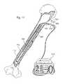
- FIG. 1is a perspective view of an intramedullary bone fixation device according to one embodiment of the invention, comprising a support structure which includes a cage and a plurality of rods, and a thermo-chemically activated thermoplastic matrix;
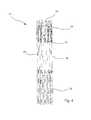
- FIG. 2is a perspective view of the cage of FIG. 1 ;
- FIGS. 3A-3Iare perspective views of various embodiments of stent portions suitable for incorporation into the support structure of FIG. 2 ;
- FIG. 4is an enlarged perspective view of a first end of the cage of FIG. 2 ;
- FIG. 5is a perspective view of the rods of FIG. 1 ;
- FIG. 6is a perspective view of the thermoplastic matrix of FIG. 1 ;
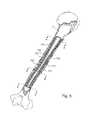
- FIG. 7is a longitudinal cross-sectional view of a bone with an alternative embodiment of an intramedullary bone fixation device partially inserted into the intramedullary canal;
- FIG. 8is a longitudinal cross-sectional view of a bone with the intramedullary bone fixation device of FIG. 7 implanted inside a second intramedullary bone fixation device;
- FIG. 9Ais an enlarged cross-sectional view of one section of the bone and intramedullary bone fixation devices of FIG. 8 ;
- FIG. 9Bis an enlarged cross-sectional view of another section of the bone and intramedullary bone fixation devices of FIG. 8 ;
- FIG. 9Cis an enlarged cross-sectional view of another section of the bone and intramedullary bone fixation devices of FIG. 8 ;
- FIG. 10is a perspective cutaway view of an alternative embodiment of an intramedullary bone fixation device comprising a cage, rods, sutures and a thermoplastic matrix;
- FIGS. 11A-11Eare cross-sectional views of the intramedullary bone fixation device of FIG. 10 , illustrating radial expansion of the device from a contracted state in FIG. 11A to a fully expanded state in FIG. 11E .
- FIGS. 12A-12Eare cross-sectional views of an alternative embodiment of an intramedullary bone fixation device, illustrating radial expansion of the device from a contracted state in FIG. 12A to a fully expanded state in FIG. 12E .
- FIG. 13Ais a perspective view of a support structure in a contracted state according to one alternative embodiment of the invention.
- FIG. 13Bis a perspective view of the support structure of FIG. 13A in an expanded state
- FIG. 14Ais a perspective view of a cage in a contracted state
- FIG. 14Bis an end view of the cage of 14 A in a contracted state
- FIG. 14Cis a perspective view of a cage in an expanded state
- FIG. 14Dis an end view of the cage of 14 C in an expanded state
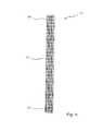
- FIG. 15is a perspective view of a slotted support structure
- FIG. 16Ais a perspective view of a shaft portion of a mechanical expansion apparatus suitable for use with the device of FIG. 1 ;
- FIG. 16Bis a perspective view of the complete mechanical expansion apparatus of FIG. 16A ;
- FIG. 17is a longitudinal cross-sectional view of a bone with an intramedullary bone fixation device in a contracted state and a balloon expansion apparatus in the intramedullary canal of the bone, and a regulator apparatus;
- FIG. 18is a longitudinal cross-sectional view of a portion of the bone of FIG. 17 , with the intramedullary bone fixation device in a contracted state and a balloon expansion apparatus of FIG. 17 ;
- FIG. 19is a longitudinal cross-sectional view of the bone, intramedullary bone fixation device and balloon expansion apparatus of FIG. 17 , with the balloon in an inflated state and the intramedullary bone fixation device in an expanded state;
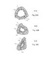
- FIG. 20Ais an enlarged cross-sectional view of one section of the bone and intramedullary bone fixation device of FIG. 19 ;
- FIG. 20Bis an enlarged cross-sectional view of another section of the bone and intramedullary bone fixation device of FIG. 19 ;
- FIG. 20Cis an enlarged cross-sectional view of another section of the bone and intramedullary bone fixation device of FIG. 19 ;
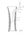
- FIG. 21is a longitudinal cross-sectional view of the bone, intramedullary bone fixation device and balloon expansion apparatus of FIG. 17 , with the balloon in a deflated state and the and intramedullary bone fixation device in an expanded state, with the balloon expansion apparatus partially removed from the intramedullary bone fixation device;
- FIG. 22Ais a perspective view of a telescoping bone fixation device in an extended state according to one alternative embodiment of the invention.
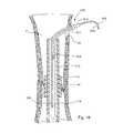
- FIG. 23is a perspective view of a telescoping bone fixation device with mesh-like components and a thermoplastic matrix according to another alternative embodiment of the invention, in an extended state;
- FIG. 24is a perspective view of a helically threaded telescoping bone fixation device according to yet another alternative embodiment of the invention, in a partially extended state;
- FIG. 25Ais a perspective view of one nesting component of the helically threaded telescoping bone fixation device of FIG. 24 ;
- FIG. 25Bis a perspective view of another nesting component of the helically threaded telescoping bone fixation device of FIG. 24 ;
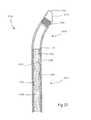
- FIG. 26is a perspective view of a composite intramedullary bone fixation device
- FIG. 27is a cross-sectional view of the proximal end of the composite intramedullary bone fixation device of FIG. 26 ;
- FIG. 28Ais a side view of a handle
- FIG. 28Bis proximal end view of the handle of FIG. 28A ;
- FIG. 29is a lateral partial cross-sectional view of a fractured bone
- FIG. 30is a lateral view of a guidewire being inserted into the intramedullary canal of the fractured bone of FIG. 29 ;
- FIG. 31is a lateral view of the handle of FIG. 28A guiding the composite intramedullary bone fixation device of FIG. 29 over the guidewire of FIG. 30 into the fractured bone;
- FIG. 32is a lateral view of the guidewire of FIG. 30 being removed from the intramedullary canal of the fractured bone;
- FIG. 33is a lateral perspective view of the handle of FIG. 28A and a balloon expansion apparatus
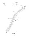
- FIG. 34is a lateral perspective view of a tube which comprises a portion of the balloon expansion apparatus of FIG. 33 ;
- FIG. 35is a lateral perspective view of the balloon expansion apparatus of FIG. 33 ;
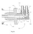
- FIG. 36is an enlarged cross-sectional view of a connection assembly of the balloon expansion apparatus of FIG. 33 ;
- FIG. 37is a lateral view of the composite intramedullary bone fixation device and the handle, connected to a set of hoses;
- FIG. 38is a lateral view of the composite intramedullary bone fixation device, handle, and hoses of FIG. 37 , connected to a cartridge and a pump, and showing the expansion of a portion of the bone fixation device;
- FIG. 39is a lateral view of the expanded composite intramedullary bone fixation device in the intramedullary canal of the fractured bone;
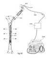
- FIG. 40is a perspective view of an implanted composite intramedullary bone fixation device connected to a heat source, an expansion apparatus and a pump;
- FIG. 41is a perspective view of a balloon expansion apparatus with a heating mechanism integrated into the balloon;
- FIG. 42is a perspective view of a balloon expansion apparatus with a heating mechanism integrated into a sleeve covering the balloon.
- FIG. 43is a perspective view of an implanted composite intramedullary bone fixation device and expansion apparatus connected to an air heating and pressure control system.
- FIG. 1a perspective view illustrates an embodiment of an intramedullary bone fixation composite device 10 , where composite is defined as at least two non-identical materials deliberately combined to form a heterogeneous structure with desired or intended properties.
- the composite device 10comprises a support structure 11 and a thermo-chemically activated thermoplastic matrix 16 .
- the support structure 11comprises a cage 12 , and at least one stiffening rod 14 .
- the composite device 10is generally tubular in form and has a longitudinal axis 24 and a transverse axis 26 .
- a hollow central core 18extends the length of the device 10 , surrounded by the cage 12 and rods 14 , which are embedded in the thermoplastic matrix 16 .
- An outer perimeter 22bounds the outer surface of the composite device 10 .
- the composite device 10is an implant which is able to transition from a contracted and flexible state for introduction into the intramedullary canal, to an expanded and hardened state providing rigid support and alignment for fixation of the surrounding bone, once implanted and allowed to expand to the perimeter of the canal.
- the thermoplasticity of the matrix 16allows the composite device 10 to conform to the shape of the surrounding intramedullary canal at a first state, and harden in its conformed shape at a second state providing torsional, axial, and bending reinforcement of the bone fragments during bone healing.
- a diameter 20 along the transverse axis 26 of the deviceis reduced, and the length along the longitudinal axis 24 of the device may be constant or increased.
- the diameter 20is increased, and the length may be constant or decreased.
- the cage 12is an elongated, generally web-like tube which allows radial expansion and contraction over at least part and preferably all of its length, and bending flexibility as bending loads are applied.
- the cage 12has a first end 30 , a second end 32 and a sleeve 34 which extends between the ends.
- the sleeve 34has an attachment portion 36 and a web-like stent portion 38 .
- the cageis hollow and generally circular in cross-sectional shape, although the web-like construction allows the cross-sectional shape to vary to conform to the contours of the surrounding intramedullary canal.
- the shape of the intramedullary canalvaries along its length, and its cross-sectional shape may be substantially circular, generally triangular or another shape.
- the cage 12may comprise a tubular woven or braided cage, a laser cut tubing cage, a machined cage, or a chemically etched tubing cage made from materials such as Nitinol, stainless steel, Co—Cr, Titanium alloys, Tantalum, plastic, polymer, ceramic or other biocompatible materials, among others.
- the stent portion 38comprises a majority of the sleeve 34 .
- the stent portionmay be a smaller proportion of the sleeve, or comprise the entire sleeve.
- Attachment portions 36may be located at one, both, or neither of the ends of the sleeve, or intermittently along the sleeve length.
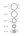
- FIG. 3possible configurations of the web-like structure of the stent portion 38 are shown, comprising examples of commercially available stent shapes. These figures show the approximate pattern of the web-like structure. These patterns are adaptable to a variety of lengths, diameters, density of repeatable patterns, wire thicknesses, web areas, and other structural characteristics such that the general stent shape can be configured to a particular bone morphology and size.
- FIG. 3Ais representative of a Johnson and Johnson Palmaz-SchatzTM Version 2 stent.
- FIG. 3Brepresents a Medtronic WiktorTM stent.
- FIG. 3Crepresents the general shape of a Schneider “Magic” WallstentTM stent.
- FIG. 3Drepresents a Scimed NIRTM stent.
- FIG. 3Erepresents an Arterial Vascular Engineering (AVETM) Microstent.
- FIG. 3Fis representative of a Biotronik StentTM.
- FIG. 3Gis meant to represent the general shape and construct of a Johnson and Johnson Palmaz-SchatzTM stent.
- FIG. 3Hrepresents a Global Therapeutics FreedomTM stent.
- FIG. 3Iis drawn to represent the adaptable structure of a Scimed RadiusTM stent which like all the previously presented representative figures can be configured to the length, diameter and size needed to conform to the intramedullary shape of a particular bone.
- the stent portionmay also be configured with more than one pattern along its length or diameter if needed to better conform to the desired geometry.
- the stent portionneed not be a commercially available stent; it may also have a unique configuration which is constructed from wire, woven, machined, laser cut, or chemically etched.
- FIG. 4is an enlarged view of the first end 30 , the attachment portion 36 and part of the stent portion 38 of the cage 12 .
- the attachment portion 36comprises struts 40 which extend from the stent portion 38 and terminate at loops 42 , which allow for the attachment of instruments for device placement, adjustment and removal. Other fasteners such as holes or hooks, among others, may be used instead of loops.
- linkages 44connect each strut to the adjacent strut. The linkages allow for radial and longitudinal contraction and expansion of the struts 40 and therefore the first end 30 , as the device is contracted and expanded during implantation and removal.
- the web-like configuration of the stent portion 38allows for radial and longitudinal contraction and expansion of the remainder of the cage 12 .
- At least one, and optionally, a plurality, of stiffening rods 14are oriented parallel to the longitudinal axis of the cage 12 and are contained by the cage in such a way as to allow the stiffening rod(s) to move radially with the cage as the cage contracts and expands.
- Each rod 14has a first end 50 , a second end 52 and a shaft 56 .
- Each rod 14may have loops, holes, hooks or other attachment structures at the second end 52 to connect to second end 32 of cage 12 .
- the rods 14may be threaded loosely or otherwise linked into the stent portion 38 of the cage 12 .
- the rods 14may extend the full length of the cage 12 , or preferably from the second end 32 of the cage to the upper end of the stent portion 38 .
- the stiffening rods 14can be made from any biocompatible material such as stainless steel, cobalt chromium alloys, tantalum, zirconium alloys, titanium or titanium alloys, particularly beta titanium alloys.
- the stiffening rods 14can also be made from non-metal biocompatible materials such as PEEK, Acetal, bioabsorbable materials, ceramics and biocomposites.
- Each stiffening rod 14is sufficiently flexible to temporarily bend as the device (in a contracted state) is introduced into the intramedullary canal. Additionally, the rods may be knurled, threaded or otherwise treated to provide adhesion and interdigitation of the matrix and cage. Once the device 10 is inserted and expanded radially, the rods 14 are aligned parallel to the longitudinal axis of the bone and line the inner surface of the canal, within the cage and matrix of the device.
- the ratio of longitudinal contraction to radial expansion of the composite device 10varies depending upon the configuration of the stent portion of the cage, the length of the linkages, and the length and placement of the rods. Some embodiments have a low ratio, in which a small decrease in the length of the cage results in a large increase in the radial expansion (as measured by change in the core diameter 20 ). Other embodiments have a 1:1 ratio (a contraction in cage length results in an equal measurement of radial expansion), or a higher ratio, in which a large decrease in longitudinal contraction produces a small increase in radial expansion. The choice of embodiment will depend upon factors such as the length and diameter of the particular bone to be fixed, accessibility to the bone, and severity of the fracture, among others.
- the thermoplastic matrix 16may be thermo-mechanically or thermo-chemically activated, and may surround the support structure 11 of FIG. 2 , or the support structure of any of the embodiments described below.
- the matrix 16comprises a thermo-chemically activated material which has physical properties that change between a first and second state.
- the materialmay be flexible and deformable at a first state and harder and more rigid at a second state. This can be accomplished by changing factors such as the molecular structure of chemical components of the matrix 16 from one state to another.
- thermo-chemically activated materialsare materials which have physical properties which may change between a first state and second state by chemical, thermal, or other processes which change the molecular structure of a material, and thus the physical properties of the material. These processes may include, but are not limited to: changing the temperature of the material, exposing the material to gamma radiation and altering the crosslinking bonds between molecular chains in the material, exposing the material to ultraviolet radiation causing the material to cure and harden, exposing the material to a second material allowing cross-linking and molecular bonding, allowing the material to harden over time by increasing the crystallinity within the molecular structure, and other methods that alter the bonding between the molecules in the material and correspondingly alter its material properties.
- thermo-chemically activatedmay also be referred to as thermoplastic.
- the matrix 16may comprise a thermoplastic biocompatible polymer or polymer blend comprising polymers such as polylactic acid (PLA), poly ⁇ -caprolactone (PCL), trimethylene carbonate (TMC), polyglycolic acid (PGA), poly l-lactic acid (PLLA), poly d-l-lactide (PDLLA), poly-D,L-lactic acid-polyethyleneglycol (PLA-PEG) or other biocompatible polymers.
- PVApolylactic acid
- PCLpoly ⁇ -caprolactone
- TMCtrimethylene carbonate
- PGApolyglycolic acid
- PLLApoly l-lactic acid
- PLLApoly d-l-lactide
- PLA-PEGpoly-D,L-lactic acid-polyethyleneglycol
- Each of these polymershas a glass transition temperature T g such that when raised to a temperature above its T g , the polymer is rubbery, flexible and substantially deformable. When lowered to a temperature below its T g ,
- Each of these polymers or blendsis capable of being transformed by the application of energy to a first thermo-chemical state, in which it is at a temperature above its glass transition temperature T g .
- T gglass transition temperature
- the polymer or blendis at a second thermo-chemical state.
- Preferred polymershave a glass transition temperature T g that is above body temperature, but below the temperature known to cause thermal necrosis of tissues.
- a preferred blendis crystallized and substantially rigid at human body temperature, and has a T g which ranges from about 10° C. above body temperature to about 35° C. above body temperature. This acceptable T g range is between about 50° C. and about 80° C., and preferably between about 55° and about 65° C.
- the thermoplastic matrix 16comprises a blend of polymers such as PCL and PLA, or PCL and PGA. Table 1 displays the melting points (T m ), glass transition temperatures (T g ) and thermal decomposition temperatures (T dec ) of selected synthetic absorbable polymers.
- Additional biocompatible polymerswhich may be included in the matrix 16 , individually or in a blend, comprise aliphatic polyesters including polyglycolide, poly(dl-lactide), poly(l-lactide), poly( ⁇ -valerolactone), polyhydroxybutyrate; polyanhydrides including poly[bis(p-carboxyphenoxy)propane anhydride], poly(carboxy phenoxyacetic acid), poly(carboxy pheoxyvaleric acid); polyphosphazenes including aryloxyphosphazene polymer and amino acid esters; poly (ortho esters); poly(p-dioxane); poly(amino acids) including poly(glutamic acid-co-glutamate); erodable hydrogels; and natural polymers including collagen (protein) and chitosan (polysaccharide).
- aliphatic polyestersincluding polyglycolide, poly(dl-lactide), poly(l-lactide), poly( ⁇ -valerol
- the thermoplastic matrix 16may further include at least one bioactive material to promote growth of bone material and accelerate healing of fractures.
- bioactive materialsinclude but are not limited to hydroxylapatite, tetracalcium phosphate, ⁇ -tricalcium phosphate, fluorapatite, magnesium whitlockite, ⁇ -whitlockite, apatite/wollastonite glass ceramic, calcium phosphate particle reinforced polyethylene, bioactive glasses, bioactive glass ceramics, polycrystalline glass ceramics, and polyethylene hydroxylapatite.
- the support structure 11may be embedded in the thermoplastic matrix 16 through insert molding, pultrusion, by dipping the support structure into the thermoplastic matrix material while it is at a temperature above T g , or by other coating methods. A variety of different methods may alternatively be used to assemble the thermoplastic matrix 16 and the support structure 11 .
- Composite device 710comprises a support structure 711 and a thermo-chemically activated thermoplastic matrix 716 .
- the support structure 711comprises a stent-like cage 712 (not shown) and a plurality of rods 714 (not shown).
- a percutaneous portal 60is created into the intramedullary canal 2 , preferably in the proximal or distal metaphysical region of the bone.
- the openingmay not be parallel to the longitudinal axis of the bone; it may be transverse or at an acute angle relative to the longitudinal axis of the bone. If necessary to open the canal space and prepare it for the implant, the canal is evacuated using a sequence of pulse lavage, brushing, and suction.
- a delivery tube 62may be advanced into the percutaneous portal 60 .
- thermoplastic matrix 716is above its glass transition temperature and is therefore substantially deformable and rubbery enough to be flexed as it is introduced through the percutaneous portal and into the intramedullary canal.
- a structureis “substantially deformable” when it requires significantly less force to deform the structure than when it is “substantially hardened”. In the preferred embodiment, a structure is substantially deformable when is requires less than half the force to deform it than would be required in the substantially hardened state.
- Heating of the composite device 710 to reach the first thermo-chemical statemay be accomplished by means including soaking the implant in a hot saline bath, application of ultrasonic vibratory energy, application of radiant heat energy, use of a local radiation emitter (including ultraviolet, visible light, and/or microwave energy), use of a laser energy emitter, use of inductive heat energy, electrical resistive heating of the cage or the delivery instrument, or heating of an expansion apparatus, among others.
- a hot saline bathapplication of ultrasonic vibratory energy, application of radiant heat energy, use of a local radiation emitter (including ultraviolet, visible light, and/or microwave energy), use of a laser energy emitter, use of inductive heat energy, electrical resistive heating of the cage or the delivery instrument, or heating of an expansion apparatus, among others.
- the composite device 710is inserted into the delivery tube 62 , pushed through the tube and advanced into the intramedullary canal 2 until the composite device 710 is contained within the confines of the canal.
- the composite device 710may be inserted directly through the percutaneous portal 60 without passing through a delivery tube 62 .
- a portion of the composite device 710may be surrounded by a protective sheath 749 , which is positioned so that it covers the device 710 at the point of the bone fracture. The device 710 is then expanded radially.
- the stiffening rods 714 , the cage 712 and thermoplastic matrix 716move radially outward and are eventually aligned along the wall of the intramedullary canal, parallel to the longitudinal axis of the bone.
- the composite device 710is allowed to cool to below the low glass transition temperature T g , thus attaining the second thermo-chemical state, and the matrix 716 crystallizes. As the matrix crystallizes it becomes substantially hardened and conforms to the shape of the surrounding intramedullary canal, and the cage 712 and stiffening rods 714 are fixed in the thermoplastic matrix 716 along the wall of the canal.
- the shape of the intramedullary canalcan vary along the length of the bone, with the canal being generally circular in the diaphysical region near the midpoint of the bone and irregular in the metaphysical regions near the ends of the bone.
- the thermoplastic matrix 716is in a generally tubular shape as the composite device 710 is inserted, the thermoplastic qualities of the matrix allow it to conform to the shape of the intramedullary canal around it, and it crystallizes in that shape, thus providing torsional strength and support to the surrounding bone.
- the ability of the thermoplastic matrix 716 to conform to the irregularities in the intramedullary canalallows the device 710 , and the stabilized bone, to withstand greater torsional forces than would a device with a constant circular shape which did not conform to the canal.
- substantially hardenedmeans the thermoplastic matrix is crystallized and sufficiently hard that it will not change shape when exposed to manual pressure or mechanical pressures.
- Deformation and/or radial expansion and of the composite device 710 to conform to the intramedullary canalcan be accomplished in several ways.
- a deformation apparatus(such as those shown in FIGS. 16 and 17 ) may be introduced into the central core of the composite device 710 before or after it has been inserted into the intramedullary canal. The deformation apparatus is expanded, and forces radial expansion of the composite device 710 until it fills the confines of the canal.
- the deformation apparatusmay comprise a heat source to raise the temperature of the thermoplastic matrix 716 .
- the cage 712may be constructed with an outward spring bias, introduced into the intramedullary canal and allowed to expand.
- a balloon apparatus(such as that shown in FIG.
- a longitudinal cross-sectionshows two composite devices 710 , 750 implanted in a bone. Deploying two bone fixation devices nested in this manner may provide additional strength, rigidity and resistance to torsion than would be available from one bone fixation device. Twice the thermoplastic matrix material and twice the support structure are present to provide additional stabilization.
- Composite device 750comprises a thermoplastic matrix 756 , which surrounds a support structure which includes a cage 752 and a plurality of rods 754 .
- the configuration of matrix 756 , cage 752 and rods 754may be identical to that of composite device 710 .
- the composite device 750Prior to implantation, the composite device 750 is partially radially expanded.
- the composite device 710is contracted, and slid into a hollow central core 758 of the composite device 750 . Together, the two devices 710 , 750 are heated until the thermoplastic matrices 716 , 756 reach the first thermo-chemical state.
- the two devices 710 , 750are introduced as a unit into the intramedullary canal.
- the inner disposed composite device 710is expanded using one of the techniques previously described. As the inner composite device 710 expands, it pushes radially against the outer disposed composite device 750 , forcing it to expand radially until it contacts and conforms to the wall of the surrounding intramed
- composite devices 710 , 750may be introduced individually into the intramedullary canal.
- Composite device 750may be introduced first, heated and expanded.
- Composite device 710is then introduced into the hollow central core 758 of composite device 750 after is it in the intramedullary canal. After both devices 710 , 750 are in the canal, composite device 710 is heated and expanded, pushing radially against the outer composite device 750 .
- thermoplastic matrix 716 surrounding the composite device 710may contact and conform to the thermoplastic matrix 758 of the composite device 750 .
- the two devices 710 , 750are allowed to cool to the second thermo-chemical state and harden.
- FIGS. 9A-9Cthree cross-sectional views along different parts of the bone depicted in FIG. 8 are shown, with devices 710 , 750 implanted in the intramedullary canal.
- the intramedullary canal 2is relatively wide and circular in shape, resulting in a wide, circular central hollow core 718 .
- the thermoplastic matrices 716 , 756are relatively thin, and the rods 714 , 754 are spaced relatively far apart, as the devices 710 , 750 had to expand radially farther to contact the wall of the intramedullary canal at that point.
- FIG. 9Bat this point along the bone the intramedullary canal is smaller in diameter and more irregular in shape.
- thermoplasticity of the matrices 716 , 756allows the devices 710 , 750 to match the size and shape of the canal. As seen in FIG. 9C , at this point along the bone the intramedullary canal is narrow in cross-section and substantially triangular in shape. According, the thermoplastic matrices 716 , 756 are thicker and the rods 714 , 754 are closer together, since the devices 710 , 750 are relatively less expanded.
- Composite device 810comprises support structure 811 and a thermo-chemically activated thermoplastic matrix 816 .
- Support structure 811comprises a cage 812 , a plurality of rods 814 , and a plurality of sutures 815 which connect the cage to the rods.
- the thermo-chemically activated matrix 816surrounds the cage 812 , rods 814 and sutures 815 such that they are embedded in the matrix.
- the sutures 815are interwoven around and between the cage 812 and the rods 814 to connect the cage 812 to the rods 814 in a manner that allows regulated movement of the cage 812 and the rods 814 relative to one another.
- the suturesmay be knit into a sleeve that holds the array of rods and surrounds the cage.
- the interweavingmay be constructed in such a way as to allow radial expansion of the cage 812 and the rods 814 from a contracted position in which the cage 812 is lengthened and the rods 814 are tightly packed together, to an expanded position in which the cage 812 is shortened, radially expanded and the rods 814 are arrayed around the cage with relatively more space between each rod.
- the cage 812may comprise web-like stent material similar to stents depicted in FIGS. 3A-3I , or may comprise another woven or laser cut stent-like material.
- the rods 814may be similar to the rods 14 depicted in FIG. 5 .
- the thermo-chemically activated thermoplastic matrix 816may be similar to the thermo-chemically activated thermoplastic matrix 16 described previously and depicted in FIG. 6 .
- the suturesmay comprise any of several commercially available sutures, including Dyneema Purity® Ultra High Molecular Weight Polyethylene (UHMWPE), or bioabsorbable multifilament polylactic acid (PLA) sutures such as PANACRLTM, among others.
- UHMWPEUltra High Molecular Weight Polyethylene
- PLAbioabsorbable multifilament polylactic acid
- Composite device 810may be introduced into the intramedullary canal in the same manner as previously described for composite device 710 . Energy is applied to composite device 810 , heating it until the thermo-chemically activated matrix 816 reaches the first thermo-chemical state, and is flexible and rubbery. The composite device 810 is contracted so that it is sufficiently flexible to be inserted into the intramedullary canal through an opening in the bone, an opening which may not be parallel to the intramedullary canal. The composite device 810 is inserted into the canal and expanded by one of the expansion methods previously described. When the device is expanded within the intramedullary canal, the thermo-chemically activated matrix 816 contacts and is conformed to the walls of the intramedullary canal. The device 810 is allowed to cool and the thermo-chemically activated matrix 816 attains the second thermo-chemical state, and hardens sufficiently to fix the support structure 811 in its expanded position within the intramedullary canal.
- FIGS. 11A-11Ea series of five cross-sectional views illustrate the expansion of composite device 810 from a contracted position to a fully expanded position.
- a hollow central core 818 of composite device 810is substantially circular.
- the cage 812 and the hollow central core 818increase in diameter and the thermoplastic matrix 816 stretches to fit around the cage 812 .
- the thermoplastic matrix 816is substantially thinner than at the most contracted state.
- the array of rods 814are relatively closely packed near one another; in FIG. 11E they are spread apart and are substantially equidistantly arrayed about the hollow central core 818 .
- FIGS. 12A-12Eillustrate an alternative embodiment of a composite device in five cross-sectional views.
- composite device 910comprises a support structure 911 with a cage 912 , a plurality of rods 914 , and a plurality of sutures 915 which connect the cage to the rods.
- a thermo-chemically activated thermoplastic matrix 916surrounds the cage 912 , rods 914 and sutures 915 such that they are embedded in the matrix.
- the thermoplastic matrix 916is configured in a series of folds 917 , as compared to the circular configuration seen for thermoplastic matrix 816 in FIG. 11C .
- thermoplastic matrix 916results in a star-shaped hollow central core 918 .
- the star-shaped hollow central core 918is smaller in terms of cross-sectional open space, as much of the space is taken up by the folds of the thermoplastic matrix 916 . Therefore, the thermoplastic matrix 916 is thicker in this embodiment than in other embodiments such as device 810 .
- the fully expanded composite device 910has a thicker thermoplastic matrix, which may result in additional support for the surrounding bone during the healing process.
- Composite device 910may be introduced into the intramedullary canal in the same manner as previously described for composite devices 710 and 810 .
- Energyis applied to composite device 910 , heating it until the thermo-chemically activated matrix 916 reaches the first thermo-chemical state, and is substantially deformable, flexible and rubbery.
- the composite device 910is contracted into the deeply folded position seen in FIG. 12A , so that it is sufficiently flexible to be inserted into the intramedullary canal through an opening in the bone.
- the composite device 910is inserted into the canal and radially expanded by one of the expansion methods previously described.
- a specifically configured implant expandersuch as a star-shaped balloon expansion device (not shown) may be used to expand the device 910 .
- thermo-chemically activated matrix 916contacts and is conformed to the walls of the intramedullary canal.
- the device 910is allowed to cool and the thermo-chemically activated matrix 916 attains the second thermo-chemical state, and substantially hardened, fixing the cage 912 and rods 914 in their expanded positions within the intramedullary canal.
- two composite devices 910may be deployed, one inside the other, to provide additional support to the bone.
- an hourglass shapeis a generally longitudinal, columnar shape in which the two end portions of the column are wider in diameter than a middle portion of the column.
- the support structure 71comprises a cage 72 and rods 14 .
- the diameters of cage ends 74 , 76are greater than the diameter of a cage sleeve 78 .
- a thermoplastic matrixis not shown. A matrix similar to that of the thermoplastic matrix 16 of FIG.
- the hourglass shapeenables the tubular support structure 71 to conform to the contours of the intramedullary canal of a long bone, in which the metaphysical regions at the ends of the bone are irregular and may be greater in diameter than the diaphysical region near the midpoint of the bone.
- the hourglass shapeis achieved by the particular threading of the rods within the stent portion of the cage.
- the rods 14are contained within the confines of the cage 72 ; toward the center of the sleeve 78 , the cage is contained within the circle of the rods 14 .
- the support structure 71is shown in the contracted state (for insertion or removal); in FIG. 13B , the expanded state is shown.
- the support structure 71may be inserted in the same manner as described previous for support structure 11 , and the same expansion methods described previously may be used to expand the support structure 71 .
- an intramedullary bone fixation devicecomprises a laser-cut cage which is constructed with an outward spring bias.
- the deviceis compressed prior to implantation by holding the rods steady and pulling longitudinally on the cage.
- the web-like configuration of the cagepermits the cage to lengthen while simultaneously its core diameter contracts, enabling the device to be narrow and flexible enough for insertion.
- the deviceis introduced into the intramedullary canal and the cage is released.
- the outward spring bias of the cagecauses the cage to expand radially and simultaneously shorten. Radial expansion continues until the outer perimeter of the device contacts the inner wall of the intramedullary canal.
- the web-like configuration of the cagealso allows it to conform to variations in the geometry of the intramedullary canal.
- This embodimentmay also include the thermoplastic matrix, wherein prior to the compression step described above, the thermoplastic matrix is heated to the substantially deformable first thermo-chemical state, so it is flexible as the device is compressed, inserted and expanded. After insertion and radial expansion, the energy is allowed to dissipate and the thermoplastic matrix attains the substantially hardened second thermo-chemical state.
- FIGS. 14A through 14Danother alternative embodiment of the invention comprises a cage with an outward spring bias, which may be used in conjunction with a thermoplastic matrix such as that depicted in FIGS. 1 and 6 .
- FIG. 14Ais a perspective view of a cage 112 , cut with a plurality of accordion-type folds 114 which unfold as the cage expands radially. Alternating with the folds 114 are longitudinal ribs 116 , and a hollow central core 115 extends the length of the cage 112 .
- Each rib 116has a longitudinal channel 118 which may hold a stiffening rod.
- the cagemay be laser-cut or machined from metal, or may comprise a plastic material or a thermo-chemically activated thermoplastic matrix material, as described above.
- the cage 112may have a straight shape with a constant diameter, or may have an hourglass shape in which the two ends are wider than the central section. Other shapes may alternatively be used for different bone morphologies.
- FIG. 14Bis an end view of the cage 112 in a compressed state, showing the tight compaction of the folds 114 and ribs 116 .
- FIG. 14Cis a perspective view of the cage 112 after radial expansion
- FIG. 14Dis an end view of the expanded cage 112 .
- the support structurecan be compressed for implantation by a binding material which is wrapped or tied around the compressed cage. After insertion into the intramedullary canal, the cage is released by cutting or removal of the binding material. Once released, the outward spring bias of the cage 112 causes the cage 112 to expand radially in the same manner as described for the previous embodiment.
- the support structuremay be monolithic; that is, formed as a single unit.
- the cage and rodsare formed together, such as by a machining process and remain connected together.
- FIG. 15an embodiment of a monolithic support structure 111 is shown in an expanded state.
- This embodimenthas no channels for rods, but consequently has ribs 117 between the accordion folds 114 which are solid and comprise more material, thus providing rigidity similar to the rods of other embodiments. Between the ribs 117 , the accordion folds 114 have a plurality of slots 119 .
- the slots 119allow for less material and thus more flexibility of the support structure when compressed.
- the monolithic support structure 111may be used in conjunction with a thermoplastic matrix. Contraction, insertion and expansion of the monolithic support structure 111 may be in the same manner as described previously for the cage 112 .
- At least two support structures and/or cagessuch as those depicted in FIGS. 14 and 15 can be nested, one within the other.
- a first support structure 111 or cage 112 embedded in the thermoplastic matrix 16is heated to the first thermo-chemical state, compressed, inserted into the intramedullary canal, and expanded.
- a second support structure 111 or cage 112 embedded in the thermoplastic matrix 16is similarly compressed and inserted into the central core 115 of the first support structure. When the second structure 111 or cage 112 expands, it pushes radially against the first structure 111 or cage 112 .
- the thermoplastic matrix 16 surrounding the first support structureconforms to the contours of the intramedullary canal.
- thermoplastic matrix 16 surrounding the second support structureconforms to the surrounding first support structure.
- the matrix material surrounding both the first and second structurescools to the second thermo-chemical state and crystallizes. This double layer of matrix material and support structures provides enhanced support and rigidity to the surrounding bone.
- the cage 112 and support structure 111 embodiments depicted in FIGS. 14 and 15can alternatively be constructed without an outward spring bias.
- the compressed cage 112 or support structure 111may be surrounded by the thermoplastic matrix 16 .
- the deviceis heated so the thermo-plastic matrix 16 reaches the first thermo-chemical state and the device is flexed and inserted into the intramedullary canal.
- an expansion apparatus or balloon mechanismas previously described, or other expansion mechanism is inserted into the central core 115 and used to expand the device after it is implanted.
- energydissipates into the surrounding tissue, the matrix attains the second thermo-chemical state, and the cage 112 or support structure 111 is fixed within the cooled, crystallized matrix 16 .
- the expansion apparatus, balloon mechanism, or other expansion mechanismmay then be removed from the central core 115 .
- an intramedullary bone fixation composite devicecomprises a thermoplastic matrix which is not continuous along the entire length of the corresponding cage or support structure.
- the matrixcomprises at least two separate tube-like portions, each of which surrounds one end of the cage or support structure and extends partway along the sleeve. This discontinuous configuration of the matrix contributes to an hourglass shape and allows less matrix material to be used.
- This matrix configurationcan be used with either a cage with an outward spring bias, or with a cage with no outward spring bias.
- an intramedullary bone fixation composite devicecomprises a support structure which comprises at least one rod, and no cage.
- the matrixPrior to implantation, the matrix is heated to the first thermo-chemical state and formed into a tubular shape around the rods, which are subsequently embedded in the matrix.
- the deviceis flexed and inserted into the patient.
- an expansion apparatus or balloonis inserted into the center of the tubular device and used to expand the device within the intramedullary canal.
- the rods and the matrix materialare pushed radially to the inner wall of the intramedullary canal.
- the deviceAfter expansion, the device is allowed to cool to the second thermo-chemical state, and the matrix hardens, fixing the rods in their positions around the inner wall of the canal.
- an intramedullary bone fixation devicecomprises a support structure which comprises a cage manufactured of the thermoplastic matrix material, and rods.
- the matrix materialis heated above its T g and extruded into a cage-like form.
- the rodsare interwoven, braided in, or otherwise attached as described previously.
- the deviceis heated above the T g of the matrix to attain the first thermo-chemical state, contracted, flexed, inserted and expanded as described previously.
- FIGS. 16A and 16Billustrate an implant expansion device which may be used to deform and expand several of the intramedullary bone fixation devices described previously, such as composite device 10 , composite devices 710 , 750 and 810 , a device incorporating support structure 71 , or other devices which incorporate a cage or support structure without an outward spring bias.
- a mechanical expansion apparatus 500is longitudinally insertable into the central core of the intramedullary bone fixation device. As seen in FIG. 16A , the mechanical expansion apparatus 500 has a shaft 514 , which extends from a first end 510 to a second end 512 . An adjustment nut 516 is threaded onto a threaded portion 515 of the shaft 514 , adjacent the first end 510 .
- a cone-shaped first expander guide 518is also threaded onto the threaded portion 515 of the shaft 514 , on the opposite side of the adjustment nut 516 from the first end 510 .
- the second end 512 of the shaft 514terminates in a cone-shaped second expander guide 519 .
- the shaft 514comprises a metallic material, and is sufficiently thin and flexible to be inserted into the central core of an intramedullary bone fixation while the device is in the intramedullary canal of a bone in a patient.
- strung on the central shaft 514 and listed in their order of occurrence from the first expander guide 518 to the second expander guide 519are: a first expander segment 520 , a plurality of core segments 522 , a central segment 524 , another plurality of core segments 522 , and a second expander segment 526 .
- the core segments 522 and the central segment 524comprise a relatively rigid material, while the expander segments 520 , 526 comprise a relatively rubbery, flexible material.
- the first expander segment 520surrounds a portion of the first expander guide 518 in a sleeve-like manner
- the second expander segment 526similarly surrounds a portion of the second expander guide 519 in a sleeve-like manner.
- the core segments 522 , central segment 524 , and expander segments 520 , 526are initially placed loosely on the shaft 514 with space between each segment, so that the apparatus can flex while being inserted into the central core of the intramedullary bone fixation device.
- the mechanical expansion apparatus 500may be inserted through the delivery tube 62 (not shown) into the central core of the intramedullary bone fixation device. Then the adjustment nut 516 is turned, forcing the first expander guide 518 to advance along the shaft 514 toward the second expander guide 519 at the second end 512 . The first expander segment 520 , core segments 522 , central segment 524 , and second expander segment 526 are compressed together as they are held between the first and second expander guides 518 , 519 .
- the rubbery, flexible expander segments 520 , 526expand radially as they are forced farther onto the cone-shaped expander guides 518 , 519 . As the expander segments 520 , 526 expand radially, they push the ends of the surrounding intramedullary bone fixation device outward radially, thus matching the generally hourglass shape of the intramedullary canal. Expansion is ceased when the outer perimeter of the intramedullary bone fixation device contacts the inner walls of the intramedullary canal.
- the expansion apparatus 500may be kept in the central core of the intramedullary bone fixation device until the thermoplastic matrix cools to the second thermo-chemical state. The expansion apparatus 500 is contracted by turning the adjustment nut 516 in the opposite direction, and the apparatus 500 is then removed from the central core.
- the expansion apparatus 500may optionally include a heating element. In this configuration, it can heat the thermoplastic matrix of an intramedullary bone fixation device while in a patient, in order to adjust the conformity of the matrix within the intramedullary canal.
- an alternative method to deform and expand an intramedullary bone fixation devicecomprises an implant deformer which is a balloon expansion apparatus.
- a balloon expansion apparatus 600configured to fit within a composite device 10 in the intramedullary canal of a bone comprises an elastic bladder 602 with an opening 604 .
- a set of flexible hosescomprising an input hose 606 and an output hose 608 are configured to extend from a regulator apparatus 610 , through the opening 604 and into the elastic bladder 602 .
- the regulator apparatus 610is external to the patient, and comprises a pump to regulate flow, and a temperature regulator to regulate the temperature, of liquid which can flow into and out of the elastic bladder 602 .
- FIG. 17depicts the hoses adjacent and parallel to one another; however they may be configured in alternative arrangements, including a concentric arrangement in which one hose surrounds the other.
- the hoses 606 , 608terminate at differing positions within the bladder 602 .
- a composite device 710 with a balloon expansion apparatus 600 already inserted into the central core 718is introduced into the intramedullary canal of a bone.
- Introduction into the bonecan be through the method described previously, in which the composite device (with the balloon apparatus in the central core) is heated so that the matrix attains the first thermo-chemical state.
- the composite device 710 plus balloon apparatus 600are flexed and introduced into the intramedullary canal through the percutaneous portal 60 .
- a delivery tube 62(not shown) may optionally be used during the introduction and expansion procedures.
- the input 606 and output 608 hosesare inserted through the balloon opening 604 ideally before the composite device 710 plus balloon apparatus 600 are introduced into the intramedullary canal, but can optionally be inserted into the balloon opening 604 after introduction into the intramedullary canal.
- a protective sheath 49may surround the composite device 710 at the location of the bone fracture.
- the external regulator apparatus 610pumps heated liquid such as water or saline solution, among others, through the input hose 606 into the elastic bladder 602 .
- the heat of the liquidmaintains the thermoplastic matrix 716 of the composite device 710 at the deformable first thermo-chemical state.
- the bladderexpands.
- the bladder 602eventually pushes outward, inducing radial expansion of the composite device 710 .
- cage and rod components of the support structure 711are connected in a web-like construction which allows them to expand radially.
- thermoplastic matrix 716 surrounding the support structure 711is at the heated first thermo-chemical state and is pushed radially by the expanding support structure, conforming to the surrounding intramedullary canal walls.
- the flexible, rubbery character of the matrixallows it to fit into the natural morphological variations in the wall of the intramedullary canal.
- a mesh-like end cap 746 on a second end 732 of the composite device 710prevents the elastic bladder 602 from escaping or ballooning out of the second end 732 .
- the output hose 608which terminates at a location different from that of the input hose 606 , allows liquid to flow out of the balloon apparatus 600 .
- the regulator apparatus 610maintains the flow, temperature and pressure of the liquid.
- FIGS. 20A-20Cdisplay cross-sections of the bone and the composite device 710 at three different locations along the length of the bone shown in FIG. 19 .
- the cross-sectional shape of the intramedullary canalis relatively circular.
- the device 710has expanded to the wall of the canal, the matrix 716 is relatively thin, and the rods 714 are spaced relatively far apart.
- the canalis smaller and more rectangular in shape than at cross-section A-A.
- the deformable nature of the matrix 716allows the matrix and the entire composite device 710 to expand differentially and conform to this variation in shape of the intramedullary canal.
- the cross-sectional shape of the intramedullary canalis relatively smaller, and has a triangle-like shape.
- the matrix 716 and the composite device 710can conform to this irregular shape.
- the rods 714are relatively closer together and the matrix 716 is relatively thicker.
- the ability of the composite device 710 to closely conform to the confines of the intramedullary canalallows the device to withstand greater torsional forces than would a device with a constant circular shape which did not conform to the canal.
- the balloon expansion apparatus 600is depicted being withdrawn from the composite device 710 .
- the liquid in the elastic bladder 602may be cooled by pumping cool liquid in through input hose 606 and withdrawing warmer liquid through output hose 608 until a consistently cooler liquid is in the bladder 602 .
- the cooler liquid in the bladderabsorbs thermal energy from the matrix 716 , allowing it to cool and transform from the flexible first thermo-chemical state to the hardened second thermo-chemical state.
- the remaining liquidmay be pumped out of the elastic bladder 602 , and the balloon expansion device 600 is pulled out of composite device 710 through the percutaneous portal 60 .
- a protective, tubular insertion sheathmay surround all or a portion of any of the above-described intramedullary bone fixation devices during the implantation procedure, and may optionally be removed following implantation.
- the insertion sheathmay be very thin, and may prevent portions of the support structure or matrix from snagging on or scratching the intramedullary canal, or portions of the fractured bone. Once the device is inserted, the sheath may be removed by being pulling the sheath out through the delivery tube, while leaving the device behind.
- x-ray, fluoroscopy, or other radiographic methodsmay be implemented to assess the alignment of the device relative to the bone. If alignment is unsatisfactory, a heating element (not shown) or a heatable expansion device such as the balloon apparatus 600 or mechanical expansion apparatus 500 as described previously may be introduced into the central core. The device is heated so the thermoplastic matrix again reaches first thermo-chemical state, and the device may then be removed and reinserted or otherwise adjusted until a satisfactory alignment is achieved. The device is allowed to cool, so the thermoplastic matrix returns to the second thermo-chemical state through the natural dissipation of energy into the surrounding tissue.
- a heating elementnot shown
- a heatable expansion devicesuch as the balloon apparatus 600 or mechanical expansion apparatus 500 as described previously may be introduced into the central core.
- the deviceis heated so the thermoplastic matrix again reaches first thermo-chemical state, and the device may then be removed and reinserted or otherwise adjusted until a satisfactory alignment is achieved.
- the deviceis allowed to cool, so the thermoplastic matrix returns to the second thermo-chemical state through
- the devicemay be removed if desired.
- the method of removalwill vary, depending on the state of the decomposition of the biocompatible thermoplastic matrix. If the thermoplastic matrix is still intact, a percutaneous portal may be opened and a tube may be inserted. The tube may be the same as or similar to the delivery tube 62 described previously.
- a heating element or heatable expansion apparatussuch as the mechanical expansion apparatus 500 or balloon expansion apparatus 600 is introduced into the central core, and the device is heated until the matrix reaches the first thermo-chemical state, above the glass transition temperature.
- the heat sourceis removed; the device may be contracted by holding the rods steady and pulling longitudinally on the cage.
- the devicemay be removed through the delivery tube, or directly through the percutaneous portal. If the thermoplastic matrix has been sufficiently absorbed so that it is no longer intact, no heating is required; the device is contracted and removed.
- Another embodiment of the inventioncomprises a support structure and an alternative form of the thermoplastic matrix, comprising an injectable form of a synthetic biodegradable polymer, poly-D,L-lactic acid-polyethyleneglycol (PLA-PEG).
- This biodegradable compositeis temperature-sensitive so that when it is heated it takes on a liquid, semi-solid form and following injection, cools and becomes semi-solid.
- a structuresuch as support structure 11 , 711 , 811 or 71 is introduced into the intramedullary canal.
- the structuremay have a protective sheath surrounding the portion of the structure which will be adjacent to the fracture location.
- heated PLA-PEGis injected through a flexible tube or catheter which is inserted through the delivery tube 62 into the central core.
- the liquid PLA-PEGflows through the web-like support structure, filling the canal and surrounding the support structure.
- the protective sheathprevents the PLA-PEG from contacting the fractured area of the bone.
- the PLA-PEGis allowed to cool and harden, and provides rigid support around the structure.
- FIG. 22Aa perspective view shows another embodiment of the invention, comprising a telescoping intramedullary fixation device 210 .
- This devicecomprises a central wire 212 surrounded by a series of five tubular nesting components 213 - 217 .
- Each tubular nesting componentis substantially the length of the entire device 210 when all components are nested together, and each successive nesting component is slightly wider in diameter than the component it surrounds.
- Other embodiments of the telescoping intramedullary fixation device 210may have fewer, or more, than five nesting components.
- the central wire 212may have a solid core and may not be tubular, but is slender and thus sufficiently flexible to be inserted into the intramedullary canal.
- the nesting components 213 - 217may comprise metal, a biocompatible polymer material, or a mesh-like stent material (such as those depicted in FIG. 3 ), and may be embedded in a thermoplastic matrix material.
- FIG. 22Adisplays the telescoping device 210 in a fully extended or telescoped position; however when completely implanted in a patient the device 210 is in a collapsed position in which the nesting components are concentrically nested together.
- the first nesting component 213 surrounding the central wire 212is slightly wider in diameter than the central wire 212 .
- Each successive nesting component 214 - 217is slightly wider than the preceding one, and as the nesting components increase in diameter, the width of the wall of the component may decrease so that each nesting component is still flexible enough to be inserted into the canal.
- the wall thickness of each of the nesting components 213 - 217may advantageously be selected such that the nesting components 213 - 217 are all nearly equally flexible. According to one alternative embodiment (not shown), the nesting components do not have solid walls but have slots in the walls to increase flexibility.
- the central wire 212may first be inserted into the intramedullary canal. Then, successive nesting components 213 - 217 with increasing diameters are introduced into the intramedullary canal. The nesting component 213 with the smallest diameter is slid in around the central wire 212 ; the nesting component 214 with the next largest diameter is slid in surrounding the first nesting component 213 , and the remaining nesting components 215 - 217 are inserted in a similar fashion. The largest nesting component 217 fits just inside the walls of the canal.
- an injectable, hardenable polymersuch as bone cement or a biocompatible polymer such as PLA-PEG may be introduced into the canal to fill any spaces between the largest nesting component 217 and the wall of the canal.
- the largest nesting component 217may have a sheath 219 which prevents the polymer from accessing the fractured area of the bone, as described previously.
- the nested set of nesting components 213 - 217has a combined strength and rigidity which exceeds that of any of the individual nesting components, and the device 210 provides strength and support during bone healing.
- FIG. 22Bis an enlarged, stylized cross-sectional view of the connection between nesting components 216 and 217 ; however the figure is representative of the connections between each of the nesting components 213 - 217 .
- Nesting component 217has a first end 230 with an inward-projecting first lip 234 .
- the next smallest nesting component 216has a second end 232 with an outward-projecting second lip 236 .
- the projecting lips 234 , 236allow for easy removal of the apparatus. During removal, initially a slap hammer is used to break the largest nesting component 217 away from the bone cement.
- Nesting component 217is pulled out first, and its inwardly-projecting lip 234 hooks the outwardly-projecting lip 236 of the next largest nesting component 216 , and causes it to be pulled out next, followed by the next largest nesting component 215 , until all the nesting components 213 - 217 are pulled out.
- the central wire 212is removed separately after all the nesting components are removed.
- telescoping fixation device 310comprises a series of nesting components 313 - 317 , each of which comprises a mesh-like stent portion embedded in thermo-plastic matrix material 318 similar to that of the thermoplastic matrix 16 of FIGS. 1 and 6 .
- Each nesting component 313 - 317is substantially the length of the entire device 310 when all components are nested together.
- the device 310Prior to implantation, the device 310 is heated as described previously so that the thermoplastic matrix material 318 reaches the first thermo-chemical state, and is rubbery and flexible.
- the device 310is telescoped out into an extended configuration, and introduced into the intramedullary canal through an opening transverse to the longitudinal axis of the bone.
- the central wire 312is introduced first, and the adjacent and smallest nested component 313 is inserted so it nests around the central wire.
- the next smallest nested component 314is nested about the smallest nested component 313 , and so on until all the remaining nested components 315 - 317 are introduced into the intramedullary canal and nested together.
- the device 310is allowed to cool so that energy dissipates into the surrounding tissue, and the thermoplastic matrix material 318 of each nesting component 313 - 317 reaches the second thermo-chemical state, and hardens.
- telescoping fixation device 410comprises a series of nesting components 413 - 417 , which are helically threaded so that during implantation each nesting component is threaded onto the preceding smaller component.
- the direction of the threading on each nesting componentmay alternate, so that each nesting component is threaded onto the next nesting component in the opposite direction from the previous one.
- Each nesting component 413 - 417is substantially the length of the entire device 410 when all components are nested together.
- five nesting componentsare described, however in alternate embodiments the number and size of the nesting components may vary.
- device 410has a central wire 412 which is initially inserted into the intramedullary canal through a delivery tube 62 or similar interface.
- the first nesting component 413is slid in around the central wire.
- the first nesting component 413is tubular in form has a clockwise helical protrusion 420 which protrudes on the outside of the tube, winding in a clockwise direction along the length of the nesting component 413 .
- two adjacent helically threaded nesting componentshave threading configurations which wind in opposite directions.
- the second nesting component 414has a clockwise helical slot 422 which winds clockwise along its length, and a counter-clockwise helical protrusion 421 which winds counter-clockwise along its length.
- nesting component 414is inserted into the intramedullary canal, it is twisted clockwise so that its clockwise helical slot 422 fits over the clockwise helical protrusion 420 on the first nesting component 413 .
- FIG. 25Atwo adjacent helically threaded nesting components have threading configurations which wind in opposite directions.
- the second nesting component 414has a clockwise helical slot 422 which winds clockwise along its length, and a counter-clockwise helical protrusion 421 which winds counter-clockwise along its length.
- the third nesting component 415has a counter-clockwise helical slot 423 , and a clockwise helical protrusion 420 . It is inserted and threaded onto the second nesting component 414 in a counter-clockwise fashion, so that its counter-clockwise helical slot 423 engages with the counter-clockwise helical protrusion 421 on the second nesting component 414 . Each remaining nesting component is threaded clockwise or counter-clockwise to engage with the smaller component nested inside of it.
- the outermost nesting component 417may or may not have a helical protrusion.
- the helical threading systemvaries in direction so that the entire device will not be loosened when the outermost component 417 is turned in one direction.
- this bi-directional threading systemadds overall torsional strength to the telescoping fixation device 410 , since a twisting force in one direction will not disengage all the threading on the nesting components.
- the telescoping fixation device 410may be used in conjunction with an injectable hardenable polymer, such as bone cement or a biocompatible polymer such as PLA-PEG, among others.
- the fixation device 410may be implanted as described previously, and the injectable polymer may then be injected into the intramedullary canal around the periphery of the device, to fix the device in place.
- the outermost nesting component 417may have a protective sheath 419 which prevents the polymer from accessing the fractured area of the bone, as described previously. Removal of the device 410 is accomplished by breaking the device away from the polymer as described previously, then unthreading and removing each component 413 - 417 in a clockwise or counter-clockwise direction, beginning with the outermost component 417 and proceeding inward.
- Fixation device 1010which may also be described as an intramedullary nail, has an elongated shape and comprises a distally located nose portion 1012 , a central portion 1014 occupying a middle position, and a proximally located attachment portion 1016 .
- a bore 1017extends the length of the device.
- the fixation device 1010is designed to be inserted into the intramedullary canal of a fractured bone along a path that is not parallel to the intramedullary canal, and once inserted may be radially expanded to fill the intramedullary canal and provide rigid support to the bone during healing.
- the fixation device 1010may be cannulated along its entire length.
- the central portion 1014may be composite, where composite is defined as at least two non-identical materials deliberately combined to form heterogeneous structures with desired or intended properties.
- a composite central portionmay comprise a metal support structure which is embedded in thermo-chemically activated matrix material.
- the two non-identical materialsare the metal which comprises the support structure, and the matrix material.
- the nose portion 1012 and the attachment portion 1016may each be non-composite, in that each may comprise one material, such as matrix material, metal or metal alloy, ceramic, or polymer, among others.
- the nose portion 1012 of the fixation device 1010has a distal tip 1018 , and a proximal transition end 1020 where the nose portion 1012 joins the central portion 1014 .
- the nose portion 1012may be substantially tapered from the transition end 1020 to the tip 1018 . This taper allows for easier introduction of the nose portion 1012 into the intramedullary canal, and may match the morphology of the distal end of the intramedullary canal.
- the nose portion 1012may be made of a thermo-mechanically or thermo-chemically activated thermoplastic matrix material, and may be radially expandable.
- the thermo-chemically activated thermoplastic matrix materialis configured to be substantially deformable at a first thermo-chemical state, and substantially hardened at a second thermo-chemical state.
- the thermoplastic matrix materialmay comprise a combination of PCLM-12, SMC-7, and A-6.
- PCLM-12is a polyaxial copolymer made of about 98/2 (molar) ⁇ -caprolactone/glycolide. The polymer is made using stannous octanoate and triethanolamine as the catalyst and initiator, respectively.
- the composition of PCLM-12protected in part by U.S. Pat. No. 7,048,753, which is incorporated herein by reference.
- SMC-7is a segmented copolymer made of about 88/12 (molar) l-lactide/trimethylene carbonate using 1,3-propanediol and stannous octanoate as the initiator and catalyst, respectively.
- composition of SMC-7is protected by U.S. Pat. Nos. 7,192,437 and 6,342,065, and European Patent 1,057,844, which are incorporated herein by reference.
- A-6is a microparticulate nucleating agent, and is protected in part by a number of patents including U.S. Pat. No. 6,413,539 and European Patents 0,737,703 and 0,952,171, which are incorporated herein by reference.
- the nose portion 1012may be formed of a matrix material comprising 95 to 99.9% by weight of a blend of PCLM-12 and SMC-7, and 11 to 5% of A-6. More specifically, the nose portion may comprise a matrix material comprising a blend of PCLM-12, SMC-7, and A-6, in which the PCLM-12 may range from 30 to 70% by weight, the SMC-7 may range from 30 to 70% by weight, and the A-6 may range from 0.1 to 5% by weight. Still more specifically, the nose portion 1012 may be made of a matrix material comprising 98% by weight of a blend of 45% by weight of PCLM-12 and 55% by weight of SMC-7; and 2% by weight of A-6.
- the attachment portion 1016is a substantially rigid, slightly curved tube which extends proximally from a proximal end of the central portion 1014 .
- the attachment portion 1016may be curved so that it may reach from the substantially straight intramedullary canal to an opening created in the bone, which opening may be transverse to the longitudinal axis of the intramedullary canal.
- the attachment portion 1016joins the central portion 1014 at a distal transition end 1030 .
- At a proximal end 1032is an opening 1034 .
- the opening 1034may be shaped to mate with a handle used the device insertion process.
- an attachment connection feature 1036which may comprise threads, slots, protrusions, grooves or other elements which may be used to connect the device 1010 to hoses, expansion apparatuses, or other devices.
- the attachment portion 1016may be made from a rigid material such as a metal or metal alloy, to provide rigid support during manipulation such as insertion or removal of the device 1010 . More specifically, the attachment portion 1016 may be made from cobalt-chrome-molybdenum (CCM).
- CCMcobalt-chrome-molybdenum
- the central portion 1014may be generally straight and tube-like, and may be capable of radial expansion, so that in an expanded state within the intramedullary canal it may provide support to the surrounding fractured bone.
- the central portion 1014may be composite, comprising a support structure and a thermo-chemically activated thermoplastic matrix.
- the support structure 1040is a laser-cut stent, cut from CCM.
- the CCM of the support structuremay be continuous with the CCM of the attachment portion 1016 .
- the CCM of the support structuremay be press-fit or otherwise joined to the CCM of the attachment portion.
- the support structure 1040is laser-cut to a pattern of ribs 1042 interconnected by web-like struts 1044 .
- the laser-cut patternallows the central portion 1014 to flex when necessary, such as during insertion and removal of the device 1010 . It also allows for radial expansion of the central portion 1014 ; when outward pressure is applied from within the central portion, the orientation of the struts shifts to allow expansion.
- the wavy portions of the struts 1044can bend and flex, without breaking.
- One aspect of the laser-cut patternis that it may minimize elastic recovery such that once expanded, the support structure 1040 may exhibit minimal drift back to its original shape.
- support structurescomprising other laser-cut patterns or other methods of manufacture may be included.
- the support structure 1040is embedded in a thermo-mechanically or thermo-chemically activated thermoplastic matrix 1048 through an injection molding process.
- a thermo-mechanically or thermo-chemically activated thermoplastic matrix 1048is injection molded so that it surrounds the support structure 1040 and the support structure is embedded within it.
- the fixation device 1010is cannulated, so the matrix 1048 is not solid across the transverse cross section of the device; instead the matrix 1048 is a hollow tube in which the support structure is embedded.
- the inner surface of the tubeis an inner bore wall 1050
- the outer surfaceis an outer wall 1052 .
- the matrix 1048may extend proximally past the proximal end of the central portion 1014 and may surround some fraction of the attachment portion 1016 . At the distal end of the central portion, the matrix 1048 may be continuous with the matrix material comprising the nose portion 1012 , may abut it, or may overlap some of the nose portion.
- the matrix 1048may be made of the same thermo-chemically activated thermoplastic matrix material of which the nose portion 1012 is made.
- the matrix 1048may comprise a combination of PCLM-12, SMC-7, and A-6.
- the matrix 1048may be made of a matrix material comprising 95 to 99.9% by weight of a blend of PCLM-12 and SMC-7, and 11 to 5% of A-6.
- the matrix 1048may comprise a matrix material comprising a blend of PCLM-12, SMC-7, and A-6, in which the PCLM-12 may range from 30 to 70% by weight, the SMC-7 may range from 30 to 70% by weight, and the A-6 may range from 11 to 5% by weight.
- the matrix 1048may be made of a matrix material comprising 98% by weight of a blend of 45% by weight of PCLM-12 and 55% by weight of SMC-7; and 2% by weight of A-6.
- FIG. 28Adepicts a handle 1100 which may be releasably connected to the proximal end of the fixation device 1010 .
- the handle 1100has a handle body 1110 , with a proximal end 1102 and a distal end 1104 .
- An ergonomic gripping portion 1112encompasses the body 1110 near its proximal end 1102 .
- a proximal connection feature 1106is located at the body proximal end 1102
- a distal connection feature 1108is located at the body distal end 1104 .
- the distal connection feature 1108is configured to connect with the attachment connection feature 1036 on the fixation device 1010 .
- the distal connection feature 1108comprises threads, however in other embodiments it may comprise slots, grooves, protrusions, or other elements configured to mate with the attachment connection feature 1036 . Additionally, the distal end 1104 may have a mating feature 1116 configured to mate with the opening 1034 of the attachment portion 1016 of the fixation device 1010 .
- FIG. 28Bis an end view of the body proximal end 1102 of the handle 1100 .
- the proximal connection feature 1106is seen as a series of threads; however it may comprise threads, slots, grooves, protrusions or other elements, in other embodiments of the invention.
- Extending lengthwise through the handleis a bore 1114 .
- the handlemay be connected to the fixation device 1010 and used to insert the fixation device 1010 into the intramedullary canal of the bone.
- the handlemay also be used as an intermediate connection piece between an expansion apparatus and a pump system which supplies fluid to the expansion apparatus.
- FIGS. 29-32illustrate how the fixation device 1010 may be inserted into the intramedullary canal of a bone.
- FIG. 29is a perspective, partially cutaway view of a fractured tibia 2 .
- an opening 4is drilled in the tibia, distal of the growth plate, so that bone growth will not be disturbed, which may be of special importance in pediatric patients.
- the intramedullary canal 6extends substantially the length of the bone, and is surrounded by a wall 8 .
- a removable guidewire 1150may be inserted through the opening 4 into the intramedullary canal 6 , in the direction indicated by direction arrow 1152 .
- the guidewiremay comprise Nitinol or another material which is sufficiently flexible to bend as it passes through the opening 4 .
- the fixation device 1010is connected to the handle 1100 at the proximal end of the attachment portion 1016 .
- the handle 1100is used to guide the fixation device 1010 over the guidewire 1150 into the intramedullary canal 6 , along direction 1152 .
- fixation device 1010is cannulated along its entire length, and the handle 1100 has a bore extending its entire length, so both the fixation device and the handle may be guided over the guidewire.
- the central portion 1014 of the fixation devicecomprises the flexible support structure 1040 and the thermoplastic matrix 1048 , which make the central portion 1014 sufficiently bendable to enter the intramedullary canal through the opening 4 .
- the fixation devicePrior to insertion of the fixation device 1010 , the fixation device may be heated in a water bath or by other means so that the thermo-chemically activated thermoplastic matrix 1048 attains the first thermo-chemical state, and is substantially deformable to bend as it enters the opening 4 and straighten as it continues along the guidewire 1150 .
- the fixation device 1010is inserted into the intramedullary canal 6 so that the attachment portion 1016 is just inside the opening 4 .
- the handle 1100may be removed, or may remain attached to the device 1010 in preparation for a device expansion procedure.
- the guidewire 1150may be removed by pulling it proximally along direction 1154 , out of the intramedullary canal, the device 1010 and the handle 1100 .
- the device 1010may be inserted into the intramedullary canal without the use of a guidewire.
- the device 1010is heated to raise the thermoplastic matrix material 1048 to the first thermo-chemical state, attached to the handle 1100 , and inserted into the canal.
- An expansion apparatussuch as that described below may be present in the device 1010 prior to insertion, or it may be inserted into the central bore 1114 after the device 1010 is in the intramedullary canal.
- the expansion apparatus 1200comprises a catheter-like inner tube 1210 (not visible in FIG. 33 ), a balloon 1230 , the handle 1110 , and a connection assembly 1250 .
- the inner tube 1210 and balloon 1230are configured to be assembled together co-axially, that is, the inner tube 1210 fits concentrically within the balloon 1230 .
- the inner tube 1210is shown.
- the inner tube 1210is straw-like in configuration, with a tube body 1212 having a proximal end 1214 and a distal end 1216 .
- the tube body 1212may be constructed of a rigid material so that the length of the tube is fixed; it cannot lengthen or shorten along its longitudinal axis. Yet the tube body 1212 may simultaneously be bendable such that it can flex and bend along its transverse axis.
- the tube body 1212may be constructed of a linearly rigid, yet bendable material such as Nitinol. The flexibility allows the tube 1210 to be compliant enough to be inserted into the intramedullary canal. The linear rigidity prevents the tube 1210 from expanding longitudinally.
- a bullet-shaped cap 1218is at the distal end of the tube body 1212 . Just proximal to the cap 1218 , a series of ports 1220 perforate the tube body 1212 .
- the ports 1220are openings from the inside of the tube body 1212 to the outside, and may allow fluid to flow into, or out of, the inner tube.
- the balloon 1230 and the connection assembly 1250are shown.
- the balloon 1230is configured to fit over and encompass the inner tube 1210 (not visible), so that only the cap 1218 protrudes from the distal end of the balloon 1230 .
- a ring-like distal fitting 1232joins the inner tube 1210 to the balloon 1230 at their distal ends.
- the distal fitting 1232tightly joins the tube and the balloon so that they may be manipulated as one during insertion and removal procedures. Additionally, because the more compliant balloon 1230 is joined to the linearly rigid inner tube 1210 at the distal fitting 1232 , the balloon 1230 is prevented from expanding linearly when pressurized fluid is introduced into the tube and the balloon.
- the balloon 1230may comprise an elastomeric polymer, such as polyurethane, latex, silicone, or another elastomeric polymer.
- the balloon 1230may comprise a non-elastomeric polymer such as PET, UHWPE, or another non-elastomeric polymer.
- FIG. 36a cross-sectional view of the proximal ends of the tube 1210 , the balloon 1230 , and the connection assembly 1250 , is shown.
- a threaded ring 1270connects the connection assembly 1250 to the proximal connection feature 1106 of the handle 1100 .
- a connection housing 1256encompasses the connections and may allow for convenient assembly of the connections.
- the inner tube 1210protrudes for a short distance out of the balloon 1230 .
- the proximal end of the inner tube 1210opens into a first connector recess 1258 , which is indented into the connection housing 1256 .
- an inflow fluid connector 1252also opens into the first recess 1258 .
- a first flow indicator arrow 1260indicates how fluid may flow from the inflow fluid connector 1252 into the inner tube 1210 .
- the proximal end of the balloon 1230opens into a second connector recess 1262 , which is indented into the connection housing 1256 .
- an outflow fluid connector 1254also opens into the second recess 1262 .
- a second flow indicator arrow 1264indicates how fluid may flow from the balloon 1230 into the outflow fluid connector 1254 .
- the expansion apparatus 1200is shown inserted into the fixation device 1010 in the intramedullary canal.
- the balloon 1230 and inner tube 1210are not visible because they are surrounded by the fixation device 1010 .
- Insertion of the expansion apparatusmay happen by a variety of methods.
- a first methodafter the fixation device 1010 is inserted into the intramedullary canal, the handle 1100 remains attached to the fixation device 1010 , and the balloon 1230 and inner tube 1210 (connected at their proximal ends by the connection assembly 1250 ) are inserted through the handle and the fixation device. After they are fully inserted, the connection assembly 1250 is connected to the handle 1100 via the threaded ring 1270 .
- the handleis detached from the fixation device. The balloon 1230 and the inner tube 1210 are inserted through the handle and attached via the threaded ring to the connection assembly 1250 and the handle 1100 . Then, using the handle to control and guide, the balloon 1230 and the inner tube 1210 are inserted through the opening 4 and into the fixation device 1010 .
- Another method for implementing the expansion apparatusincludes inserting the apparatus 1200 into the fixation device 1010 prior to inserting the fixation device 1010 into the intramedullary canal.
- the expansion apparatus 1200is inserted into the fixation device 1010 and connection assembly 1250 is connected. Once the balloon assembly 1200 is inserted in the fixation device 1010 , fluid hoses are connected to the connection assembly 1250 .
- An input hose 1302is connected to the input fluid connector 1252
- an output hose 1304is connected to the output fluid connector 1254 . Fluid is introduced into the expansion apparatus, and heated to in turn heat the fixation device 1010 until the thermoplastic matrix material 1048 attains the first thermo-chemical state.
- Temperature regulationcontinues as the device 1010 is inserted into the intramedullary canal, so that it remains warm enough to be substantially deformable and flexible to insert. Once the device 1010 is in the intramedullary canal, pressure may be increased within the device to cause radial expansion of the device. In an alternate embodiment of the invention, air instead of fluid may be heated and circulated through the expansion apparatus to warm the surrounding thermoplastic matrix.
- the fixation device 1010 and balloon assembly 1200are shown connected via the fluid hoses 1302 , 1304 to a cartridge 1350 , which in turn is connected to a pump 1400 .
- Sterile saline solution, or another sterile, biocompatible fluidis provided to the pump via a bag or other container (not shown) connected to the pump 1400 .
- the pump 1400pumps the fluid to the cartridge 1350 , which is capable to regulate the temperature and pressure of the fluid as it flows to and from the balloon assembly 1200 .
- the cartridge 1350may comprise heating and cooling sources capable to heat and/or cool the fluid before it enters the balloon assembly 1200 .
- the hoses 1302 , 1304may be connected directly to the pump without the use of the cartridge 1350 .
- the balloon assemblymay be expanded, to result in the radial expansion of the fixation device 1010 within the intramedullary canal.
- Fluidcan flow through the balloon assembly in a continuous flow, flowing in through the input hose 1302 into the inner tube 1210 , out the ports 1220 into the balloon 1230 , and out of the balloon through the output hose 1304 .
- Fluidis supplied by the pump 1400 to the cartridge 1350 and pumped through the input hose 1302 into the inner tube 1210 .
- the fluidcan move out of the tube 1210 through the ports 1220 , and into the balloon 1230 .
- the length of the balloon 1230is filled and the balloon expands radially, contacting the inner bore wall 1050 of the matrix 1048 of the fixation device 1010 .
- the heated fluid within the balloon 1230heats the matrix 1048 , transforming it from the substantially hardened second thermo-chemical state to the substantially deformable first thermo-chemical state.
- the deformable heated matrix 1048is expanded radially in response to the expansion of the balloon 1230 .
- the outer wall 1052 of the matrixcontacts the wall 8 of the intramedullary canal.
- the deformable heated matrix 1048can conform to the specific morphology of the wall 8 , filling in any irregularities in the wall.
- the embedded support structure 1040also expands radially, allowed to by the configuration of the rods 1042 and the flexible struts 1044 .
- the nose portion 1012 of the fixation device 1010may also radially expand.
- the expanded diameters of the non-composite nose portion 1012 and the composite central portion 1014may be the same, or alternatively, the central portion 1014 may expand to a greater expanded diameter than the nose portion 1012 .
- the device 1010Once the device 1010 is sufficiently radially expanded to provide support to the fractured bone, pressure is maintained and cooled fluid may be pumped through the balloon assembly. Fluid is cooled by the cartridge 1350 and pumped in through the input hose 1302 . As the cooled fluid passes through the balloon 1230 , the surrounding matrix 1048 is cooled, and attains the substantially hardened second thermo-chemical state. The hardened matrix 1048 holds the embedded support structure 1040 in its now expanded configuration, and together they provide support to the surrounding fractured bone. Once the matrix 1048 is sufficiently cooled and hardened, pressure is lowered and the fluid may be pumped out of the balloon and inner tube, and the balloon assembly withdrawn from the fixation device 1010 .
- the handle 1100is detached from the attachment end 1016 of the fixation device, leaving the now expanded fixation device 1010 in the intramedullary canal, as shown in FIG. 39 .
- the opening 4 in the bonemay be covered with a removable plug, and the tissues closed.
- Positioning of the fixation device 1010may be revisable if necessary.
- the opening 4may be re-opened, and a balloon expansion apparatus 1200 is attached to the handle 1100 and introduced into the bore 1114 of the fixation device 1010 , and connected at the attachment connection feature 1036 .
- the cartridge 1350 and pump 1400are connected to the expansion apparatus 1200 via the connection assembly 1250 , and heated fluid is introduced into the balloon 1230 .
- Pressureis increased to inflate the balloon 1230 , and the heated fluid warms the thermo-plastic matrix material 1048 until it is at the pliable first thermo-chemical state.
- the position of the fixation device 1010may be revised by gripping the handle 1100 and moving the device 1010 . Once the desired position is found, cool fluid is pumped through the device to cool the thermo-plastic matrix 1048 to the hardened second thermo-chemical state. The fluid pressure is lowered and the expansion apparatus is removed.
- removal instead of repositioning of the device 1010may occur after warming the device to the first thermo-chemical state.
- the fluid pressureis lowered to contract the expansion apparatus 1200 , and the device is pulled out through the opening 4 .
- the warmed thermoplastic matrix material 1048will be sufficiently deformable to allow the device 1010 to contract sufficiently as it passes out the opening 4 .
- FIGS. 40 through 43illustrate alternative methods of heating the fixation device 1010 to raise the temperature of the thermoplastic matrix material 1048 to the substantially deformable first thermo-dynamic state.
- FIG. 40depicts the fixation device 1010 with an external heat source 1360 connected by a lead 1362 to the attachment portion 1016 and the support structure 1040 . Energy is conducted from the heat source 1360 to the support structure 1040 , which increases in temperature and warms the surrounding thermoplastic matrix material 1048 .
- An expansion apparatussuch as expansion apparatus 1200 may be inserted into the fixation device 1010 , connected to a pump such as pump 1400 and used to apply fluid or air pressure to expand the heated device.
- FIG. 41depicts a flexible, expandable heating system 2250 used in conjunction with a balloon expansion apparatus 2200 which is similar in structure to balloon expansion apparatus 1200 .
- the balloon 2230is shown as partially expanded so that details of the heating system may be seen.
- the expandable heating system 2250may comprise a heat source 2252 and flexible conductive elements 2254 disposed on the external surface of the balloon 2230 .
- the flexible conductive elementsmay be integrated into the composition of the balloon.
- the conductive elements 2254may comprise copper or another suitably conductive material. As the balloon is filled with fluid or air, heat is introduced from the heat source 2252 through the conductive elements 2254 , heating the fluid or air within the balloon.
- the conductive elements 2254are configured to flex and separate, without breaking, as the balloon expands. As the balloon expands within the fixation device 1010 , heat from the fluid or air is transferred to the surrounding thermoplastic matrix material 1048 . Heat may also transfer directly from the expandable heating system 2250 to the surrounding matrix material. Once the fixation device is sufficiently expanded, heat is turned off to the heating system 2250 . Pressure is maintained in the balloon until the thermoplastic matrix cools to the hardened second thermo-chemical state. Then the air or fluid is removed, and the balloon expansion apparatus may be removed.
- FIG. 42depicts a heating system 2350 which is similar in operation to heating system 2250 , except that it comprises a heat source 2352 and flexible heating elements 2354 disposed on an expandable sleeve 2356 which is separate from the balloon.
- the flexible conductive elementsmay be integrated into the composition of the sleeve.
- the expandable sleeve 2356is sized to fit over a balloon such as balloon 1230 of balloon expansion apparatus 1200 or a similar balloon.
- the expandable sleeve 2356may be placed over the balloon 1230 , and the sleeve and balloon inserted together into an intramedullary fixation device such as device 1010 .
- heatis introduced from the heat source 2352 through the flexible heating elements 2354 , warming the fluid or air within the balloon.
- the heating elements 2354are configured to flex and separate, without breaking, as the balloon expands.
- heat from the fluid or airis transferred to the surrounding thermoplastic matrix material 1048 .
- Heatmay also transfer directly from the expandable heating system 2350 to the surrounding matrix material.
- a rigid, or non-flexible sleeve with integrated heating elementscould be used in a manner similar to the expandable sleeve 2356 .
- a non-flexible sleevemay be placed over a balloon expansion apparatus and inserted into an intramedullary fixation device such as those previously described. Heat is introduced through the heating elements, warming the surrounding thermoplastic matrix material. Once the material is sufficiently warmed to attain the first thermo-chemical state and becomes pliable, the non-flexible sleeve is removed, leaving the balloon expansion apparatus in the fixation device. The balloon expansion apparatus may then be expanded with pressurized fluid or air to expand the surrounding intramedullary fixation device.
- Air heating and pressure control system 2400is shown connected to the balloon expansion apparatus 1200 (not visible; inside the fixation device 1010 ) and fixation device 1010 .
- Air heating and pressure control system 2400comprises a pump 2402 which supplies and regulates pressure to the system, a heat source 2404 which supplies heat to the system, input hose 2406 which carries air into the expansion apparatus, and output hose 2408 which carries air out of the expansion apparatus.
- Air heating and pressure control system 2400may work similarly to the cartridge 1350 and pump 1400 described previously, except that in this system air is heated and circulated throughout the balloon expansion apparatus instead of fluid.
Landscapes
- Health & Medical Sciences (AREA)
- Orthopedic Medicine & Surgery (AREA)
- Life Sciences & Earth Sciences (AREA)
- Surgery (AREA)
- Engineering & Computer Science (AREA)
- Biomedical Technology (AREA)
- Veterinary Medicine (AREA)
- Animal Behavior & Ethology (AREA)
- General Health & Medical Sciences (AREA)
- Public Health (AREA)
- Neurology (AREA)
- Heart & Thoracic Surgery (AREA)
- Nuclear Medicine, Radiotherapy & Molecular Imaging (AREA)
- Medical Informatics (AREA)
- Molecular Biology (AREA)
- Transplantation (AREA)
- Oral & Maxillofacial Surgery (AREA)
- Vascular Medicine (AREA)
- Chemical & Material Sciences (AREA)
- Optics & Photonics (AREA)
- Physics & Mathematics (AREA)
- Cardiology (AREA)
- Epidemiology (AREA)
- Dermatology (AREA)
- Medicinal Chemistry (AREA)
- Anesthesiology (AREA)
- Hematology (AREA)
- Chemical Kinetics & Catalysis (AREA)
- Prostheses (AREA)
- Surgical Instruments (AREA)
- Materials For Medical Uses (AREA)
Abstract
Description
| TABLE 1 |
| Melting, glass transition and thermal decomposition |
| temperatures of selected synthetic absorbable polymers. |
| Polymer | Tm(° C.) | Tg(° C.) | Tdec(° C.) | ||
| 230 | 36 | 260 | |||
| PLLA | 170 | 56 | 240 | ||
| PLA | — | 57 | — | ||
| 60 | −62 | — | |||
| Polyglactin910 | 200 | 40 | 250 | ||
| Polydioxanone | 106 | <20 | 190 | ||
| Polyglyconate | 213 | <20 | 260 | ||
Claims (12)
Priority Applications (8)
| Application Number | Priority Date | Filing Date | Title |
|---|---|---|---|
| US12/027,521US8167881B2 (en) | 2007-04-24 | 2008-02-07 | Implantable composite apparatus and method |
| JP2010506420AJP2010524642A (en) | 2007-04-24 | 2008-04-21 | Deformable implant system and method |
| CA002685046ACA2685046A1 (en) | 2007-04-24 | 2008-04-21 | Deformable implant systems and methods |
| EP08746463.2AEP2139432A4 (en) | 2007-04-24 | 2008-04-21 | Deformable implant systems and methods |
| PCT/US2008/061047WO2008134287A2 (en) | 2007-04-24 | 2008-04-21 | Deformable implant systems and methods |
| US13/423,914US8834468B2 (en) | 2007-04-24 | 2012-03-19 | Bone stabilization device and method |
| US14/220,132US9421045B2 (en) | 2007-04-24 | 2014-03-20 | Bone stabilization device and method |
| US15/208,861US20160317201A1 (en) | 2007-04-24 | 2016-07-13 | Bone stabilization device and method |
Applications Claiming Priority (5)
| Application Number | Priority Date | Filing Date | Title |
|---|---|---|---|
| US91369607P | 2007-04-24 | 2007-04-24 | |
| US11/777,892US8128626B2 (en) | 2007-04-24 | 2007-07-13 | System and method for delivery conformation and removal of intramedullary bone fixation devices |
| US11/777,872US20080269746A1 (en) | 2007-04-24 | 2007-07-13 | Conformable intramedullary implant with nestable components |
| US11/777,846US20080269745A1 (en) | 2007-04-24 | 2007-07-13 | Thermo-chemically activated intramedullary bone stent |
| US12/027,521US8167881B2 (en) | 2007-04-24 | 2008-02-07 | Implantable composite apparatus and method |
Related Parent Applications (1)
| Application Number | Title | Priority Date | Filing Date |
|---|---|---|---|
| US11/777,846Continuation-In-PartUS20080269745A1 (en) | 2007-04-24 | 2007-07-13 | Thermo-chemically activated intramedullary bone stent |
Related Child Applications (1)
| Application Number | Title | Priority Date | Filing Date |
|---|---|---|---|
| US13/423,914ContinuationUS8834468B2 (en) | 2007-04-24 | 2012-03-19 | Bone stabilization device and method |
Publications (2)
| Publication Number | Publication Date |
|---|---|
| US20080269750A1 US20080269750A1 (en) | 2008-10-30 |
| US8167881B2true US8167881B2 (en) | 2012-05-01 |
Family
ID=39887873
Family Applications (10)
| Application Number | Title | Priority Date | Filing Date |
|---|---|---|---|
| US11/777,846AbandonedUS20080269745A1 (en) | 2007-04-24 | 2007-07-13 | Thermo-chemically activated intramedullary bone stent |
| US11/777,892Expired - Fee RelatedUS8128626B2 (en) | 2007-04-24 | 2007-07-13 | System and method for delivery conformation and removal of intramedullary bone fixation devices |
| US11/777,872AbandonedUS20080269746A1 (en) | 2007-04-24 | 2007-07-13 | Conformable intramedullary implant with nestable components |
| US12/027,521Expired - Fee RelatedUS8167881B2 (en) | 2007-04-24 | 2008-02-07 | Implantable composite apparatus and method |
| US12/027,600Expired - Fee RelatedUS8162943B2 (en) | 2007-04-24 | 2008-02-07 | Deformable implant systems and methods |
| US12/027,555Expired - Fee RelatedUS8147492B2 (en) | 2007-04-24 | 2008-02-07 | System and method for guidance and implantation of implantable devices |
| US12/027,629AbandonedUS20080269749A1 (en) | 2007-04-24 | 2008-02-07 | Thermo-Chemically Activated Implantable Apparatus and Method |
| US13/423,914Expired - Fee RelatedUS8834468B2 (en) | 2007-04-24 | 2012-03-19 | Bone stabilization device and method |
| US14/220,132Expired - Fee RelatedUS9421045B2 (en) | 2007-04-24 | 2014-03-20 | Bone stabilization device and method |
| US15/208,861AbandonedUS20160317201A1 (en) | 2007-04-24 | 2016-07-13 | Bone stabilization device and method |
Family Applications Before (3)
| Application Number | Title | Priority Date | Filing Date |
|---|---|---|---|
| US11/777,846AbandonedUS20080269745A1 (en) | 2007-04-24 | 2007-07-13 | Thermo-chemically activated intramedullary bone stent |
| US11/777,892Expired - Fee RelatedUS8128626B2 (en) | 2007-04-24 | 2007-07-13 | System and method for delivery conformation and removal of intramedullary bone fixation devices |
| US11/777,872AbandonedUS20080269746A1 (en) | 2007-04-24 | 2007-07-13 | Conformable intramedullary implant with nestable components |
Family Applications After (6)
| Application Number | Title | Priority Date | Filing Date |
|---|---|---|---|
| US12/027,600Expired - Fee RelatedUS8162943B2 (en) | 2007-04-24 | 2008-02-07 | Deformable implant systems and methods |
| US12/027,555Expired - Fee RelatedUS8147492B2 (en) | 2007-04-24 | 2008-02-07 | System and method for guidance and implantation of implantable devices |
| US12/027,629AbandonedUS20080269749A1 (en) | 2007-04-24 | 2008-02-07 | Thermo-Chemically Activated Implantable Apparatus and Method |
| US13/423,914Expired - Fee RelatedUS8834468B2 (en) | 2007-04-24 | 2012-03-19 | Bone stabilization device and method |
| US14/220,132Expired - Fee RelatedUS9421045B2 (en) | 2007-04-24 | 2014-03-20 | Bone stabilization device and method |
| US15/208,861AbandonedUS20160317201A1 (en) | 2007-04-24 | 2016-07-13 | Bone stabilization device and method |
Country Status (5)
| Country | Link |
|---|---|
| US (10) | US20080269745A1 (en) |
| EP (1) | EP2139432A4 (en) |
| JP (1) | JP2010524642A (en) |
| CA (1) | CA2685046A1 (en) |
| WO (1) | WO2008134287A2 (en) |
Cited By (17)
| Publication number | Priority date | Publication date | Assignee | Title |
|---|---|---|---|---|
| US20110208189A1 (en)* | 2005-02-22 | 2011-08-25 | Tecres S.P.A. | Disposable device for treatment of infections of human limbs |
| US10010609B2 (en) | 2013-05-23 | 2018-07-03 | 206 Ortho, Inc. | Method and apparatus for treating bone fractures, and/or for fortifying and/or augmenting bone, including the provision and use of composite implants |
| US10028776B2 (en) | 2010-10-20 | 2018-07-24 | 206 Ortho, Inc. | Method and apparatus for treating bone fractures, and/or for fortifying and/or augmenting bone, including the provision and use of composite implants |
| US10136929B2 (en) | 2015-07-13 | 2018-11-27 | IntraFuse, LLC | Flexible bone implant |
| US10154863B2 (en) | 2015-07-13 | 2018-12-18 | IntraFuse, LLC | Flexible bone screw |
| US10485595B2 (en) | 2015-07-13 | 2019-11-26 | IntraFuse, LLC | Flexible bone screw |
| US10499960B2 (en) | 2015-07-13 | 2019-12-10 | IntraFuse, LLC | Method of bone fixation |
| US10525169B2 (en) | 2010-10-20 | 2020-01-07 | 206 Ortho, Inc. | Method and apparatus for treating bone fractures, and/or for fortifying and/or augmenting bone, including the provision and use of composite implants, and novel composite structures which may be used for medical and non-medical applications |
| US10525168B2 (en) | 2010-10-20 | 2020-01-07 | 206 Ortho, Inc. | Method and apparatus for treating bone fractures, and/or for fortifying and/or augmenting bone, including the provision and use of composite implants, and novel composite structures which may be used for medical and non-medical applications |
| US10729548B2 (en) | 2016-05-02 | 2020-08-04 | Howmedica Osteonics Corp. | Bioactive soft tissue implant and methods of manufacture and use thereof |
| US10857261B2 (en) | 2010-10-20 | 2020-12-08 | 206 Ortho, Inc. | Implantable polymer for bone and vascular lesions |
| US11058796B2 (en) | 2010-10-20 | 2021-07-13 | 206 Ortho, Inc. | Method and apparatus for treating bone fractures, and/or for fortifying and/or augmenting bone, including the provision and use of composite implants, and novel composite structures which may be used for medical and non-medical applications |
| US11154638B2 (en) | 2015-08-12 | 2021-10-26 | Howmedica Osteonics Corp. | Methods for forming scaffolds |
| US11207109B2 (en) | 2010-10-20 | 2021-12-28 | 206 Ortho, Inc. | Method and apparatus for treating bone fractures, and/or for fortifying and/or augmenting bone, including the provision and use of composite implants, and novel composite structures which may be used for medical and non-medical applications |
| US11291483B2 (en) | 2010-10-20 | 2022-04-05 | 206 Ortho, Inc. | Method and apparatus for treating bone fractures, and/or for fortifying and/or augmenting bone, including the provision and use of composite implants |
| US11331191B2 (en) | 2015-08-12 | 2022-05-17 | Howmedica Osteonics Corp. | Bioactive soft tissue implant and methods of manufacture and use thereof |
| US11484627B2 (en) | 2010-10-20 | 2022-11-01 | 206 Ortho, Inc. | Method and apparatus for treating bone fractures, and/or for fortifying and/or augmenting bone, including the provision and use of composite implants, and novel composite structures which may be used for medical and non-medical applications |
Families Citing this family (140)
| Publication number | Priority date | Publication date | Assignee | Title |
|---|---|---|---|---|
| US9060809B2 (en)* | 2001-10-18 | 2015-06-23 | Orthoip, Llc | Lagwire system and method for the fixation of bone fractures |
| US8828067B2 (en) | 2001-10-18 | 2014-09-09 | Orthoip, Llc | Bone screw system and method |
| WO2006034436A2 (en) | 2004-09-21 | 2006-03-30 | Stout Medical Group, L.P. | Expandable support device and method of use |
| US7771411B2 (en) | 2004-09-24 | 2010-08-10 | Syntheon, Llc | Methods for operating a selective stiffening catheter |
| US8961516B2 (en) | 2005-05-18 | 2015-02-24 | Sonoma Orthopedic Products, Inc. | Straight intramedullary fracture fixation devices and methods |
| US9060820B2 (en)* | 2005-05-18 | 2015-06-23 | Sonoma Orthopedic Products, Inc. | Segmented intramedullary fracture fixation devices and methods |
| US20100137923A1 (en)* | 2005-11-10 | 2010-06-03 | Zimmer, Inc. | Minimally invasive orthopaedic delivery devices and tools |
| US10123683B2 (en) | 2006-03-02 | 2018-11-13 | Syntheon, Llc | Variably flexible insertion device and method for variably flexing an insertion device |
| US9814372B2 (en) | 2007-06-27 | 2017-11-14 | Syntheon, Llc | Torque-transmitting, variably-flexible, locking insertion device and method for operating the insertion device |
| US7806900B2 (en) | 2006-04-26 | 2010-10-05 | Illuminoss Medical, Inc. | Apparatus and methods for delivery of reinforcing materials to bone |
| US7811290B2 (en) | 2006-04-26 | 2010-10-12 | Illuminoss Medical, Inc. | Apparatus and methods for reinforcing bone |
| EP2023864B1 (en) | 2006-05-01 | 2019-07-10 | Stout Medical Group, L.P. | Expandable support device |
| US7879041B2 (en) | 2006-11-10 | 2011-02-01 | Illuminoss Medical, Inc. | Systems and methods for internal bone fixation |
| CA2669129C (en) | 2006-11-10 | 2014-09-16 | Illuminoss Medical, Inc. | Systems and methods for internal bone fixation |
| WO2008064346A2 (en) | 2006-11-22 | 2008-05-29 | Sonoma Orthopedic Products, Inc. | Fracture fixation device, tools and methods |
| CA2682298C (en)* | 2007-02-23 | 2015-04-28 | Zimmer Gmbh | Implant for fracture treatment |
| JP5631597B2 (en)* | 2007-03-12 | 2014-11-26 | スタウト メディカル グループ,エル.ピー. | Expandable mounting device and method |
| PL2124831T3 (en) | 2007-03-15 | 2017-03-31 | Ortho-Space Ltd. | Prosthetic devices |
| US20080269745A1 (en)* | 2007-04-24 | 2008-10-30 | Osteolign, Inc. | Thermo-chemically activated intramedullary bone stent |
| AU2007356033B2 (en) | 2007-07-03 | 2014-05-29 | Synergy Biosurgical Ag | Medical implant |
| US8303640B2 (en)* | 2007-07-30 | 2012-11-06 | Audubon Technologies, Llc | Device for maintaining patent paranasal sinus ostia |
| KR101617051B1 (en) | 2007-09-17 | 2016-04-29 | 씨너지 바이오써지컬 아게 | medical implant |
| WO2009047767A1 (en)* | 2007-10-11 | 2009-04-16 | Tavor [I.T.N] Ltd. | Ligament and tendon prosthesis |
| US9427289B2 (en) | 2007-10-31 | 2016-08-30 | Illuminoss Medical, Inc. | Light source |
| US8403968B2 (en) | 2007-12-26 | 2013-03-26 | Illuminoss Medical, Inc. | Apparatus and methods for repairing craniomaxillofacial bones using customized bone plates |
| CA2781407A1 (en) | 2008-01-14 | 2009-07-23 | Michael P. Brenzel | Apparatus and methods for fracture repair |
| US20090263458A1 (en)* | 2008-04-21 | 2009-10-22 | Lasse Daniel Efskind | Material for surgical use in traumatology |
| US20090265016A1 (en)* | 2008-04-21 | 2009-10-22 | Lasse Daniel Efskind | Material for surgical use in traumatology |
| US20090292172A1 (en)* | 2008-05-21 | 2009-11-26 | Boston Scientific Scimed, Inc. | Expandable Delivery Devices and Methods of Use |
| GB0813659D0 (en) | 2008-07-25 | 2008-09-03 | Smith & Nephew | Fracture putty |
| WO2010045116A1 (en)* | 2008-10-14 | 2010-04-22 | Zimmer, Inc. | Modular intramedullary nail |
| WO2010056895A1 (en) | 2008-11-12 | 2010-05-20 | Stout Medical Group, L.P. | Fixation device and method |
| US20100211176A1 (en) | 2008-11-12 | 2010-08-19 | Stout Medical Group, L.P. | Fixation device and method |
| US10610364B2 (en) | 2008-12-04 | 2020-04-07 | Subchondral Solutions, Inc. | Method for ameliorating joint conditions and diseases and preventing bone hypertrophy |
| WO2010094032A2 (en)* | 2009-02-16 | 2010-08-19 | Aoi Medical Inc. | Trauma nail accumulator |
| US20100217391A1 (en)* | 2009-02-21 | 2010-08-26 | Ladd Amy L | Tensioning bone implant device |
| US20120035666A1 (en)* | 2009-02-21 | 2012-02-09 | Osteospring Medical, Inc. | Reduced Bone Fracture Fixation Device |
| US8012155B2 (en)* | 2009-04-02 | 2011-09-06 | Zimmer, Inc. | Apparatus and method for prophylactic hip fixation |
| US8210729B2 (en) | 2009-04-06 | 2012-07-03 | Illuminoss Medical, Inc. | Attachment system for light-conducting fibers |
| US8512338B2 (en) | 2009-04-07 | 2013-08-20 | Illuminoss Medical, Inc. | Photodynamic bone stabilization systems and methods for reinforcing bone |
| EP2467098A4 (en) | 2009-08-19 | 2015-07-08 | Illuminoss Medical Inc | Devices and methods for bone alignment, stabilization and distraction |
| CA2713309C (en) | 2009-08-20 | 2013-07-02 | Howmedica Osteonics Corp. | Flexible acl instrumentation, kit and method |
| WO2011038315A1 (en)* | 2009-09-28 | 2011-03-31 | Zimmer, Inc. | Expandable intramedullary rod |
| BR112012011132A2 (en)* | 2009-11-10 | 2016-07-05 | Illuminoss Medical Inc | intramedullary implants having variable fixation placement |
| JP2013512048A (en)* | 2009-11-30 | 2013-04-11 | シンセス ゲゼルシャフト ミット ベシュレンクテル ハフツング | Expandable implant |
| WO2011075745A2 (en)* | 2009-12-18 | 2011-06-23 | Palmaz Scientific, Inc. | Interosteal and intramedullary implants and method of implanting same |
| US20110178520A1 (en) | 2010-01-15 | 2011-07-21 | Kyle Taylor | Rotary-rigid orthopaedic rod |
| WO2011091052A1 (en) | 2010-01-20 | 2011-07-28 | Kyle Taylor | Apparatus and methods for bone access and cavity preparation |
| WO2011112615A1 (en) | 2010-03-08 | 2011-09-15 | Krinke Todd A | Apparatus and methods for securing a bone implant |
| US20110288652A1 (en)* | 2010-05-20 | 2011-11-24 | Indiana University Research & Technology Corporation | Materials and methods for treating critically sized defects in mouse bone |
| WO2011153454A2 (en)* | 2010-06-03 | 2011-12-08 | The University Of North Carolina At Chapel Hill | Threaded elastic intramedullary nails devices and methods |
| US8684965B2 (en) | 2010-06-21 | 2014-04-01 | Illuminoss Medical, Inc. | Photodynamic bone stabilization and drug delivery systems |
| BR112013000994A2 (en) | 2010-08-10 | 2017-07-11 | Synthes Gmbh | expandable implant |
| EP2608747A4 (en) | 2010-08-24 | 2015-02-11 | Flexmedex Llc | Support device and method for use |
| WO2012033983A2 (en)* | 2010-09-09 | 2012-03-15 | Dr. Reddy's Laboratories Ltd. | Candesartan pharmaceutical compositions |
| WO2012033836A1 (en) | 2010-09-09 | 2012-03-15 | Synthes Usa, Llc | Surgical nail |
| CN101991460A (en)* | 2010-11-16 | 2011-03-30 | 张英泽 | Gas-liquid two-phase intramedullary nail |
| US10010327B2 (en)* | 2010-12-16 | 2018-07-03 | Lawrence Livermore National Security, Llc | Expandable implant and implant system |
| EP2654584A1 (en) | 2010-12-22 | 2013-10-30 | Illuminoss Medical, Inc. | Systems and methods for treating conditions and diseases of the spine |
| TWI434668B (en) | 2011-02-10 | 2014-04-21 | Metal Ind Res & Dev Ct | Medical instrument with modular intramedullary nail |
| WO2012151088A1 (en)* | 2011-05-02 | 2012-11-08 | Cook Medical Technologies Llc | Biodegradable, bioabsorbable stent anchors |
| US8936644B2 (en) | 2011-07-19 | 2015-01-20 | Illuminoss Medical, Inc. | Systems and methods for joint stabilization |
| US20130023876A1 (en) | 2011-07-19 | 2013-01-24 | Illuminoss Medical, Inc. | Combination Photodynamic Devices |
| EP2747682A4 (en) | 2011-08-23 | 2015-01-21 | Flexmedex Llc | Tissue removal device and method |
| US9724138B2 (en) | 2011-09-22 | 2017-08-08 | Arthrex, Inc. | Intermedullary devices for generating and applying compression within a body |
| US9283006B2 (en) | 2011-09-22 | 2016-03-15 | Mx Orthopedics, Corp. | Osteosynthetic shape memory material intramedullary bone stent and method for treating a bone fracture using the same |
| EP2757998A4 (en) | 2011-09-22 | 2015-05-06 | Ams Res Corp | PELVIC IMPLANT AND TREATMENT METHOD |
| US9289307B2 (en) | 2011-10-18 | 2016-03-22 | Ortho-Space Ltd. | Prosthetic devices and methods for using same |
| EP3326558B1 (en) | 2011-11-14 | 2025-04-30 | The University of British Columbia | Intramedullary fixation system for management of pelvic and acetabular fractures |
| ES2656974T3 (en) | 2012-01-19 | 2018-03-01 | Stryker European Holdings I, Llc | Cuff for suprarrotulian surgery |
| US9554836B2 (en) | 2012-06-29 | 2017-01-31 | The Cleveland Clinic Foundation | Intramedullary bone stent |
| US8939977B2 (en) | 2012-07-10 | 2015-01-27 | Illuminoss Medical, Inc. | Systems and methods for separating bone fixation devices from introducer |
| US8968387B2 (en) | 2012-07-23 | 2015-03-03 | Abbott Cardiovascular Systems Inc. | Shape memory bioresorbable polymer peripheral scaffolds |
| US9532881B2 (en)* | 2012-08-12 | 2017-01-03 | Brian Albert Hauck | Memory material implant system and methods of use |
| US9452005B2 (en) | 2012-08-23 | 2016-09-27 | DePuy Synthes Products, Inc. | Bone fixation system |
| EP2887896B1 (en)* | 2012-08-23 | 2017-04-19 | Synthes GmbH | Bone implant |
| US10004603B2 (en) | 2012-08-23 | 2018-06-26 | DePuy Synthes Products, Inc. | Bone implant |
| US11051864B2 (en)* | 2012-08-30 | 2021-07-06 | DePuy Synthes Products, Inc. | Intramedullary fixation assembly |
| EP2897542A4 (en)* | 2012-09-23 | 2016-07-20 | Impetus Innovations Inc | A segmental reconstructive intramedullary nail and delivery system |
| TW201422268A (en) | 2012-12-07 | 2014-06-16 | Ind Tech Res Inst | Injection device and heting device thereof |
| US9687281B2 (en) | 2012-12-20 | 2017-06-27 | Illuminoss Medical, Inc. | Distal tip for bone fixation devices |
| US9585695B2 (en) | 2013-03-15 | 2017-03-07 | Woven Orthopedic Technologies, Llc | Surgical screw hole liner devices and related methods |
| CN105916458B (en)* | 2013-06-24 | 2019-09-27 | 托莱多大学 | Bioactive Fusion Devices |
| RU2526242C1 (en)* | 2013-10-03 | 2014-08-20 | Анатолий Петрович Барабаш | Intramedullary blocking device for osteosynthesis |
| CN105939677A (en) | 2013-12-12 | 2016-09-14 | 康文图斯整形外科公司 | Tissue displacement tools and methods |
| US9770278B2 (en) | 2014-01-17 | 2017-09-26 | Arthrex, Inc. | Dual tip guide wire |
| WO2015134750A1 (en) | 2014-03-06 | 2015-09-11 | University Of British Columbia | Shape adaptable intramedullary fixation device |
| RU2016143164A (en)* | 2014-04-11 | 2018-05-14 | Смит Энд Нефью, Инк. | DMLS ORTHOPEDIC INTRAMEDOLLARY DEVICE AND METHOD OF MANUFACTURE |
| KR101624614B1 (en) | 2014-07-18 | 2016-05-27 | 주식회사 케이씨스 | Shrinkage or expansion possible functional intramedullary fixation apparatus |
| US9907593B2 (en) | 2014-08-05 | 2018-03-06 | Woven Orthopedic Technologies, Llc | Woven retention devices, systems and methods |
| US8956394B1 (en) | 2014-08-05 | 2015-02-17 | Woven Orthopedic Technologies, Llc | Woven retention devices, systems and methods |
| CN104207867B (en)* | 2014-08-13 | 2017-02-22 | 中国科学院福建物质结构研究所 | Low-modulus medical implant porous scaffold structure |
| US9943351B2 (en) | 2014-09-16 | 2018-04-17 | Woven Orthopedic Technologies, Llc | Woven retention devices, systems, packaging, and related methods |
| US9814499B2 (en) | 2014-09-30 | 2017-11-14 | Arthrex, Inc. | Intramedullary fracture fixation devices and methods |
| JP6389002B2 (en) | 2014-10-14 | 2018-09-12 | ザ ユニヴァーシティ オブ ブリティッシュ コロンビア | System and method for intramedullary bone fixation |
| CN104323875B (en)* | 2014-10-14 | 2017-01-18 | 刘振东 | Bone grafting device for repairing large segmental bone defects |
| USD740427S1 (en) | 2014-10-17 | 2015-10-06 | Woven Orthopedic Technologies, Llc | Orthopedic woven retention device |
| US9925046B2 (en) | 2015-03-31 | 2018-03-27 | DePuy Synthes Products, Inc. | Bone graft cage |
| US10258472B2 (en) | 2015-03-31 | 2019-04-16 | DePuy Synthes Products, Inc. | Bone graft cage |
| US9770279B2 (en)* | 2015-05-18 | 2017-09-26 | Little Engine, LLC | Method and apparatus for extraction of medical implants |
| US20160346018A1 (en)* | 2015-06-01 | 2016-12-01 | The Texas A &M University System | Defect fixation device |
| WO2017019553A1 (en) | 2015-07-27 | 2017-02-02 | The Texas A&M University System | Medical devices coated with shape memory polymer foams |
| US10555758B2 (en) | 2015-08-05 | 2020-02-11 | Woven Orthopedic Technologies, Llc | Tapping devices, systems and methods for use in bone tissue |
| WO2017046647A1 (en) | 2015-09-18 | 2017-03-23 | Ortho-Space Ltd. | Intramedullary fixated subacromial spacers |
| US9974581B2 (en) | 2015-11-20 | 2018-05-22 | Globus Medical, Inc. | Expandable intramedullary systems and methods of using the same |
| US10111691B2 (en) | 2015-11-20 | 2018-10-30 | Globus Medical, Inc. | Expandable intramedullary systems and methods of using the same |
| US9827025B2 (en) | 2015-11-20 | 2017-11-28 | Globus Medical, Inc. | Expandable intramedullary systems and methods of using the same |
| EP3380025B1 (en)* | 2015-11-25 | 2021-01-27 | Subchondral Solutions, Inc. | Devices for repairing anatomical joint conditions |
| EP3383296B1 (en) | 2015-12-03 | 2020-05-20 | Biomet Manufacturing, LLC | Hammertoe implant promoting bony in-growth |
| US10695181B2 (en) | 2016-02-16 | 2020-06-30 | DePuy Synthes Products, Inc. | Bone graft cage |
| DE102016003838A1 (en)* | 2016-03-29 | 2017-10-05 | Merete Holding Gmbh | Implantable compensating cuff for an endoprosthesis |
| DE102016003837A1 (en) | 2016-03-29 | 2017-10-05 | Merete Holding Gmbh | Implantable compensating cuff for an endoprosthesis |
| CN105943146B (en)* | 2016-05-14 | 2020-04-17 | 苏州苏南捷迈得医疗器械有限公司 | Shape memory alloy bone plate cooler |
| CN105919663A (en)* | 2016-06-08 | 2016-09-07 | 河北医科大学第三医院 | Elastic intramedullary nail with bionic internal fixation action |
| JP6953520B2 (en) | 2016-06-13 | 2021-10-27 | デピュイ・シンセス・プロダクツ・インコーポレイテッド | Bone graft cage |
| CN106108998A (en)* | 2016-07-25 | 2016-11-16 | 南京医科大学第附属医院 | A kind of braided steel wire inner core antibiotic-loaded bone cement intramedullary pin and preparation method thereof and making mould |
| FR3054430B1 (en) | 2016-07-27 | 2018-07-27 | Centre Hospitalier Universitaire De Bordeaux | INTRA-BONE STENT |
| EP3522803A4 (en) | 2016-10-05 | 2020-05-27 | The University of British Columbia | Intramedullary fixation device with shape locking interface |
| WO2018107114A1 (en) | 2016-12-09 | 2018-06-14 | Woven Orthopedic Technologies, LLC. | Retention devices, lattices and related systems and methods |
| EP3573806A4 (en) | 2017-01-30 | 2019-12-11 | Ortho-Space Ltd. | Processing machine and methods for processing dip-molded articles |
| ES2983820T3 (en) | 2017-03-14 | 2024-10-25 | Shape Memory Medical Inc | Shape memory polymer foams for sealing a space around valves |
| US10751507B2 (en) | 2017-04-10 | 2020-08-25 | Syn Variflex, Llc | Thermally controlled variable-flexibility catheters and methods of manufacturing same |
| CN106943210B (en)* | 2017-04-21 | 2019-03-12 | 无锡市第九人民医院 | It is a kind of for wrapping up the titanium cage of long bone cortex bone ectonexine bone grafting |
| WO2019010252A2 (en) | 2017-07-04 | 2019-01-10 | Conventus Orthopaedics, Inc. | APPARATUS AND METHODS FOR TREATING BONES |
| CN109464220A (en)* | 2017-09-08 | 2019-03-15 | 重庆润泽医药有限公司 | A kind of tantalum stick for medical surgery |
| CN107981926B (en)* | 2017-09-20 | 2021-03-12 | 北京航空航天大学 | Pedicle screw with anti-pulling-out performance |
| US10888363B2 (en) | 2017-12-06 | 2021-01-12 | Stout Medical Group, L.P. | Attachment device and method for use |
| WO2019128703A1 (en)* | 2017-12-27 | 2019-07-04 | 先健科技(深圳)有限公司 | Covered stent |
| US20190215627A1 (en)* | 2018-01-11 | 2019-07-11 | Orello Hearing Technologies Inc. | Hearing assistance device |
| US11628070B2 (en) | 2018-02-26 | 2023-04-18 | Neo Medical Sa | Spine cage holder |
| US11071572B2 (en) | 2018-06-27 | 2021-07-27 | Illuminoss Medical, Inc. | Systems and methods for bone stabilization and fixation |
| WO2020076383A1 (en) | 2018-10-09 | 2020-04-16 | Frank Castro | Long bone fracture reduction system |
| CN112912022A (en) | 2018-10-17 | 2021-06-04 | 不列颠哥伦比亚大学 | Bone fixation device and system |
| FR3096883B1 (en)* | 2019-06-05 | 2023-11-24 | One Ortho | Fixation system between a medical device and at least part of a bone |
| WO2021157145A1 (en)* | 2020-02-05 | 2021-08-12 | 富士フィルター工業株式会社 | Implant for bone fracture treatment and method for manufacturing implant for bone fracture treatment |
| JP7478427B2 (en)* | 2020-02-05 | 2024-05-07 | 富士フィルター工業株式会社 | Implant for bone fracture treatment and method for manufacturing implant for bone fracture treatment |
| US11504240B2 (en) | 2020-06-04 | 2022-11-22 | DePuy Synthes Products, Inc. | Modular bone graft cage |
| US12390252B2 (en) | 2021-04-18 | 2025-08-19 | Medical Patents Llc | Fracture reduction device |
| US11925394B1 (en)* | 2022-09-01 | 2024-03-12 | MediCarbone, Inc. | Methods for creating, inserting, and removing an intramedullary sleeve system for bone treatment and stabilization |
| US20250082376A1 (en)* | 2023-09-07 | 2025-03-13 | Mirus Llc | Expandable system for repair of bone fractures |
Citations (95)
| Publication number | Priority date | Publication date | Assignee | Title |
|---|---|---|---|---|
| US4177524A (en) | 1976-05-14 | 1979-12-11 | Pfaudler-Werke A.G. | Medical securement element with abrasive grains on thread surface |
| US4204531A (en) | 1977-12-28 | 1980-05-27 | Yacov Aginsky | Intramedullary nail with expanding mechanism |
| US4262665A (en) | 1979-06-27 | 1981-04-21 | Roalstad W L | Intramedullary compression device |
| US4453539A (en) | 1982-03-01 | 1984-06-12 | The University Of Toledo | Expandable intramedullary nail for the fixation of bone fractures |
| US4457301A (en) | 1982-06-18 | 1984-07-03 | Howmedica Inc. | Intramedullary fixation device |
| US4522200A (en) | 1983-06-10 | 1985-06-11 | Ace Orthopedic Company | Adjustable intramedullar rod |
| US4721103A (en) | 1985-01-31 | 1988-01-26 | Yosef Freedland | Orthopedic device |
| US4854312A (en) | 1988-04-13 | 1989-08-08 | The University Of Toledo | Expanding intramedullary nail |
| US4932969A (en) | 1987-01-08 | 1990-06-12 | Sulzer Brothers Limited | Joint endoprosthesis |
| US5053035A (en) | 1990-05-24 | 1991-10-01 | Mclaren Alexander C | Flexible intramedullary fixation rod |
| US5108398A (en) | 1990-10-16 | 1992-04-28 | Orthopaedic Research Institute | Orthopaedic knee fusion apparatus |
| US5108404A (en) | 1989-02-09 | 1992-04-28 | Arie Scholten | Surgical protocol for fixation of bone using inflatable device |
| US5135527A (en) | 1989-10-25 | 1992-08-04 | Ender Hans G | Instrumentarium for repositioning and fixing petrochanterous and subtrochanterous fractures |
| US5281225A (en) | 1989-06-07 | 1994-01-25 | Guglielmo Vicenzi | Intramedullary pin with self-locking end for metadiaphyseal fractures of long bones |
| US5364398A (en) | 1986-06-23 | 1994-11-15 | Pfizer Hospital Products Group, Inc. | Modular femoral fixation system |
| US5423850A (en) | 1993-10-01 | 1995-06-13 | Berger; J. Lee | Balloon compressor for internal fixation of bone fractures |
| US5480400A (en) | 1993-10-01 | 1996-01-02 | Berger; J. Lee | Method and device for internal fixation of bone fractures |
| US5501695A (en) | 1992-05-27 | 1996-03-26 | The Anspach Effort, Inc. | Fastener for attaching objects to bones |
| US5620445A (en) | 1994-07-15 | 1997-04-15 | Brosnahan; Robert | Modular intramedullary nail |
| US5653709A (en) | 1992-12-04 | 1997-08-05 | Synthes (U.S.A.) | Modular marrow nail |
| US5720753A (en) | 1991-03-22 | 1998-02-24 | United States Surgical Corporation | Orthopedic fastener |
| US5725541A (en) | 1996-01-22 | 1998-03-10 | The Anspach Effort, Inc. | Soft tissue fastener device |
| US5782865A (en) | 1995-08-25 | 1998-07-21 | Grotz; Robert Thomas | Stabilizer for human joints |
| WO1998038918A1 (en) | 1997-03-07 | 1998-09-11 | Mordechay Beyar | Systems for percutaneous bone and spinal stabilization, fixation and repair |
| US5849004A (en) | 1996-07-17 | 1998-12-15 | Bramlet; Dale G. | Surgical anchor |
| US5855579A (en) | 1994-07-15 | 1999-01-05 | Smith & Nephew, Inc. | Cannulated modular intramedullary nail |
| US6083244A (en) | 1996-09-13 | 2000-07-04 | Tendon Technology, Ltd. | Apparatus and method for tendon or ligament repair |
| US6183474B1 (en) | 1996-03-13 | 2001-02-06 | Dale G. Bramlet | Surgical fastener assembly |
| US6206880B1 (en) | 2000-02-21 | 2001-03-27 | Abbas Karladani | Method for percutaneous intramedullary nailing of tibial shaft fractures |
| FR2801189A1 (en) | 1999-11-24 | 2001-05-25 | Newdeal | Bone shortening implant, especially for metatarsal bones, has anterior portion with anchoring head and posterior portion sliding into bone canal |
| US6245102B1 (en) | 1997-05-07 | 2001-06-12 | Iowa-India Investments Company Ltd. | Stent, stent graft and stent valve |
| US6248110B1 (en) | 1994-01-26 | 2001-06-19 | Kyphon, Inc. | Systems and methods for treating fractured or diseased bone using expandable bodies |
| US6261289B1 (en)* | 1998-10-26 | 2001-07-17 | Mark Levy | Expandable orthopedic device |
| US6299635B1 (en) | 1997-09-29 | 2001-10-09 | Cook Incorporated | Radially expandable non-axially contracting surgical stent |
| US6312455B2 (en) | 1997-04-25 | 2001-11-06 | Nitinol Devices & Components | Stent |
| US20010051814A1 (en) | 1999-03-17 | 2001-12-13 | Shalaby Shalaby W. | High strength fibers of iota-lactide copolymers, epsilon-caprolactone, and trimethylene carbonate and absorbable medical constructs thereof |
| US20020032444A1 (en)* | 1999-12-09 | 2002-03-14 | Mische Hans A. | Methods and devices for treatment of bone fractures |
| US6371989B1 (en) | 1996-09-13 | 2002-04-16 | Jean-Luc Chauvin | Method of providing proper vertebral spacing |
| US6413539B1 (en) | 1996-10-31 | 2002-07-02 | Poly-Med, Inc. | Hydrogel-forming, self-solvating absorbable polyester copolymers, and methods for use thereof |
| US6423067B1 (en) | 1999-04-29 | 2002-07-23 | Theken Surgical Llc | Nonlinear lag screw with captive driving device |
| US20020120291A1 (en) | 1999-03-17 | 2002-08-29 | Shalaby Shalaby W. | Coated, slow-absorbing textile constructs for sutures and tissue engineering |
| US6475237B2 (en) | 1999-05-03 | 2002-11-05 | William J. Drasler | Intravascular hinge stent |
| US20020165544A1 (en) | 1999-11-11 | 2002-11-07 | Stephan Perren | Radially expandable intramedullary nail |
| US6491718B1 (en) | 1999-10-05 | 2002-12-10 | Amjad Ahmad | Intra vascular stent |
| US6506211B1 (en) | 2000-11-13 | 2003-01-14 | Scimed Life Systems, Inc. | Stent designs |
| US6551321B1 (en) | 2000-06-23 | 2003-04-22 | Centerpulse Orthopedics Inc. | Flexible intramedullary nail |
| US6554833B2 (en) | 1998-10-26 | 2003-04-29 | Expanding Orthopedics, Inc. | Expandable orthopedic device |
| US20030109932A1 (en)* | 2000-01-03 | 2003-06-12 | Ory Keynan | Intramedullary support strut |
| US6582453B1 (en) | 2000-07-14 | 2003-06-24 | Opus Medical, Inc. | Method and apparatus for attaching connective tissues to bone using a suture anchoring device |
| US6613081B2 (en) | 1997-11-14 | 2003-09-02 | Transvascular, Inc. | Deformable scaffolding multicellular stent |
| US6626937B1 (en) | 2000-11-14 | 2003-09-30 | Advanced Cardiovascular Systems, Inc. | Austenitic nitinol medical devices |
| US6682554B2 (en) | 1998-09-05 | 2004-01-27 | Jomed Gmbh | Methods and apparatus for a stent having an expandable web structure |
| US6709454B1 (en) | 1999-05-17 | 2004-03-23 | Advanced Cardiovascular Systems, Inc. | Self-expanding stent with enhanced delivery precision and stent delivery system |
| US6746479B2 (en) | 1997-04-25 | 2004-06-08 | Scimed Life Systems, Inc. | Stent cell configurations including spirals |
| US6746477B2 (en) | 2000-03-09 | 2004-06-08 | Lpl Systems, Inc. | Expandable stent |
| US6761731B2 (en) | 2002-06-28 | 2004-07-13 | Cordis Corporation | Balloon-stent interaction to help reduce foreshortening |
| US6764506B2 (en) | 1997-02-07 | 2004-07-20 | Endosystems Llc | Non-foreshortening intraluminal prosthesis |
| US6764507B2 (en) | 2000-10-16 | 2004-07-20 | Conor Medsystems, Inc. | Expandable medical device with improved spatial distribution |
| US6770088B1 (en) | 1996-04-26 | 2004-08-03 | Scimed Life Systems, Inc. | Intravascular stent |
| US6770089B1 (en) | 2000-12-28 | 2004-08-03 | Advanced Cardiovascular Systems, Inc. | Hybrid stent fabrication using metal rings and polymeric links |
| US6776793B2 (en) | 1995-03-01 | 2004-08-17 | Scimed Life Systems, Inc. | Longitudinally flexible expandable stent |
| US6790227B2 (en) | 2001-03-01 | 2004-09-14 | Cordis Corporation | Flexible stent |
| US20040199246A1 (en)* | 2003-04-02 | 2004-10-07 | Scimed Life Systems, Inc. | Expandable stent |
| US6805706B2 (en) | 2002-08-15 | 2004-10-19 | Gmp Cardiac Care, Inc. | Stent-graft with rails |
| US6808561B2 (en) | 2000-10-16 | 2004-10-26 | University Of South Carolina | Biocompatible cement containing reactive calcium phosphate nanoparticles and methods for making and using such cement |
| US20040230193A1 (en) | 2003-04-18 | 2004-11-18 | Cheung Kenneth M.C. | Fixation device |
| US6866805B2 (en) | 2001-12-27 | 2005-03-15 | Advanced Cardiovascular Systems, Inc. | Hybrid intravascular stent |
| US6896696B2 (en) | 1998-11-20 | 2005-05-24 | Scimed Life Systems, Inc. | Flexible and expandable stent |
| US6911048B2 (en) | 2000-03-13 | 2005-06-28 | Exactech, Inc. | Modular hip prosthesis |
| US6939373B2 (en) | 2003-08-20 | 2005-09-06 | Advanced Cardiovascular Systems, Inc. | Intravascular stent |
| US20050216007A1 (en)* | 2004-03-29 | 2005-09-29 | Christian Woll | Orthopedic intramedullary fixation system |
| US6955686B2 (en) | 2001-03-01 | 2005-10-18 | Cordis Corporation | Flexible stent |
| US6962603B1 (en) | 1995-03-01 | 2005-11-08 | Boston Scientific Scimed, Inc. | Longitudinally flexible expandable stent |
| WO2005112804A1 (en) | 2004-05-21 | 2005-12-01 | Myers Surgical Solutions, Llc | Fracture fixation and site stabilization system |
| US6979349B1 (en) | 2001-06-29 | 2005-12-27 | Advanced Cardiovascular Systems, Inc. | Universal stent link design |
| US6997946B2 (en) | 2002-11-27 | 2006-02-14 | Boston Scientific Scimed, Inc. | Expandable stents |
| US6998060B2 (en) | 2001-03-01 | 2006-02-14 | Cordis Corporation | Flexible stent and method of manufacture |
| US7005136B2 (en) | 2002-03-29 | 2006-02-28 | Ethicon, Inc. | Bone replacement materials utilizing bioabsorbable liquid polymers |
| US7025777B2 (en) | 2002-07-31 | 2006-04-11 | Unison Therapeutics, Inc. | Flexible and conformable stent and method of forming same |
| US7029493B2 (en) | 2002-01-25 | 2006-04-18 | Cordis Corporation | Stent with enhanced crossability |
| US7044963B1 (en) | 1996-09-19 | 2006-05-16 | Medinol, Ltd. | Stent with variable features to optimize support and method of making such stent |
| US7052498B2 (en) | 1998-10-26 | 2006-05-30 | Expanding Orthopedics, Inc. | Expandable orthopedic device |
| US7060088B1 (en) | 1998-11-13 | 2006-06-13 | Cordis Corporation | Stent with improved flexible connecting links |
| US7081130B2 (en) | 1996-04-26 | 2006-07-25 | Boston Scientific Scimed, Inc. | Intravascular Stent |
| US7094255B2 (en) | 1996-03-05 | 2006-08-22 | Evysio Medical Devices Ulc | Expandable stent and method for delivery of same |
| US7101391B2 (en) | 2000-09-18 | 2006-09-05 | Inflow Dynamics Inc. | Primarily niobium stent |
| US7108714B1 (en) | 1997-06-13 | 2006-09-19 | Orbus Medical Technologies, Inc. | Expandable intraluminal endoprosthesis |
| US7112216B2 (en) | 2003-05-28 | 2006-09-26 | Boston Scientific Scimed, Inc. | Stent with tapered flexibility |
| US20060264950A1 (en) | 2005-05-18 | 2006-11-23 | Nelson Charles L | Minimally Invasive Actuable Bone Fixation Devices |
| US20060264945A1 (en)* | 2005-05-18 | 2006-11-23 | Edidin Avram A | Selectively-expandable bone scaffold |
| US20070213725A1 (en) | 2006-03-10 | 2007-09-13 | Hack Bradford H | Intra-medullary implant with active compression |
| US20080033522A1 (en)* | 2006-08-03 | 2008-02-07 | Med Institute, Inc. | Implantable Medical Device with Particulate Coating |
| US20080228186A1 (en) | 2005-04-01 | 2008-09-18 | The Regents Of The University Of Colorado | Graft Fixation Device |
| US20080269747A1 (en) | 2007-04-24 | 2008-10-30 | Osteolign, Inc. | System and method for delivery, conformation and removal of intramedullary bone fixation devices |
| US20090005782A1 (en) | 2007-03-02 | 2009-01-01 | Chirico Paul E | Fracture Fixation System and Method |
Family Cites Families (28)
| Publication number | Priority date | Publication date | Assignee | Title |
|---|---|---|---|---|
| US426665A (en)* | 1890-04-29 | Clamp | ||
| DE2603456C2 (en)* | 1976-01-30 | 1984-04-05 | Robert Bosch Gmbh, 7000 Stuttgart | Process for the production of a bone implant |
| JPS53144194A (en) | 1977-05-20 | 1978-12-15 | Kureha Chemical Ind Co Ltd | Compound implanted material and making method thereof |
| SU848004A1 (en)* | 1979-01-04 | 1981-07-23 | Всесоюзный Научно-Исследовательскийи Испытательный Институт Медицинскойтехники | Joining element for fixation of bone tissue |
| US4409974A (en)* | 1981-06-29 | 1983-10-18 | Freedland Jeffrey A | Bone-fixating surgical implant device |
| US5190546A (en)* | 1983-10-14 | 1993-03-02 | Raychem Corporation | Medical devices incorporating SIM alloy elements |
| FR2626276B1 (en)* | 1988-01-22 | 1990-05-11 | Hoechst France | IMPROVEMENT IN THE PROCESS FOR THE MANUFACTURE OF ALKYL PYRUVATES |
| CH676196A5 (en)* | 1988-08-30 | 1990-12-28 | Sulzer Ag | |
| US5324307A (en)* | 1990-07-06 | 1994-06-28 | American Cyanamid Company | Polymeric surgical staple |
| US5263991A (en)* | 1992-10-21 | 1993-11-23 | Biomet, Inc. | Method for heating biocompatible implants in a thermal packaging line |
| AU734539B2 (en)* | 1998-01-06 | 2001-06-14 | Aderans Research Institute, Inc. | Bioabsorbable fibers and reinforced composites produced therefrom |
| WO2000012832A2 (en) | 1998-08-26 | 2000-03-09 | Molecular Geodesics, Inc. | Radially expandable device |
| US6558414B2 (en) | 1999-02-02 | 2003-05-06 | Impra, Inc. | Partial encapsulation of stents using strips and bands |
| US7258692B2 (en)* | 2000-03-07 | 2007-08-21 | Zimmer, Inc. | Method and apparatus for reducing femoral fractures |
| DE10204904A1 (en) | 2002-02-06 | 2003-08-14 | Wittenstein Ag | Device, in particular intramedullary nail and / or sleeve for insertion into long bones |
| US20060179465A1 (en) | 2003-07-24 | 2006-08-10 | Koninklijke Philips Electroncs N.V. | Handling feature availability in a broadcast |
| AU2005206175A1 (en)* | 2004-01-16 | 2005-08-04 | Expanding Orthopedics, Inc. | Bone fracture treatment devices |
| US7091130B1 (en)* | 2004-06-25 | 2006-08-15 | Freescale Semiconductor, Inc. | Method of forming a nanocluster charge storage device |
| US7967820B2 (en)* | 2006-02-07 | 2011-06-28 | P Tech, Llc. | Methods and devices for trauma welding |
| US7811290B2 (en) | 2006-04-26 | 2010-10-12 | Illuminoss Medical, Inc. | Apparatus and methods for reinforcing bone |
| US7806900B2 (en) | 2006-04-26 | 2010-10-05 | Illuminoss Medical, Inc. | Apparatus and methods for delivery of reinforcing materials to bone |
| US20080169582A1 (en) | 2006-10-23 | 2008-07-17 | Vipul Bhupendra Dave | Method and apparatus for making polymeric drug delivery devices having differing morphological structures |
| CA2669129C (en)* | 2006-11-10 | 2014-09-16 | Illuminoss Medical, Inc. | Systems and methods for internal bone fixation |
| US7879041B2 (en) | 2006-11-10 | 2011-02-01 | Illuminoss Medical, Inc. | Systems and methods for internal bone fixation |
| US8512338B2 (en) | 2009-04-07 | 2013-08-20 | Illuminoss Medical, Inc. | Photodynamic bone stabilization systems and methods for reinforcing bone |
| EP2467098A4 (en) | 2009-08-19 | 2015-07-08 | Illuminoss Medical Inc | Devices and methods for bone alignment, stabilization and distraction |
| BR112012011132A2 (en) | 2009-11-10 | 2016-07-05 | Illuminoss Medical Inc | intramedullary implants having variable fixation placement |
| US8684965B2 (en) | 2010-06-21 | 2014-04-01 | Illuminoss Medical, Inc. | Photodynamic bone stabilization and drug delivery systems |
- 2007
- 2007-07-13USUS11/777,846patent/US20080269745A1/ennot_activeAbandoned
- 2007-07-13USUS11/777,892patent/US8128626B2/ennot_activeExpired - Fee Related
- 2007-07-13USUS11/777,872patent/US20080269746A1/ennot_activeAbandoned
- 2008
- 2008-02-07USUS12/027,521patent/US8167881B2/ennot_activeExpired - Fee Related
- 2008-02-07USUS12/027,600patent/US8162943B2/ennot_activeExpired - Fee Related
- 2008-02-07USUS12/027,555patent/US8147492B2/ennot_activeExpired - Fee Related
- 2008-02-07USUS12/027,629patent/US20080269749A1/ennot_activeAbandoned
- 2008-04-21JPJP2010506420Apatent/JP2010524642A/enactivePending
- 2008-04-21WOPCT/US2008/061047patent/WO2008134287A2/enactiveApplication Filing
- 2008-04-21CACA002685046Apatent/CA2685046A1/ennot_activeAbandoned
- 2008-04-21EPEP08746463.2Apatent/EP2139432A4/ennot_activeWithdrawn
- 2012
- 2012-03-19USUS13/423,914patent/US8834468B2/ennot_activeExpired - Fee Related
- 2014
- 2014-03-20USUS14/220,132patent/US9421045B2/ennot_activeExpired - Fee Related
- 2016
- 2016-07-13USUS15/208,861patent/US20160317201A1/ennot_activeAbandoned
Patent Citations (110)
| Publication number | Priority date | Publication date | Assignee | Title |
|---|---|---|---|---|
| US4177524A (en) | 1976-05-14 | 1979-12-11 | Pfaudler-Werke A.G. | Medical securement element with abrasive grains on thread surface |
| US4204531A (en) | 1977-12-28 | 1980-05-27 | Yacov Aginsky | Intramedullary nail with expanding mechanism |
| US4262665A (en) | 1979-06-27 | 1981-04-21 | Roalstad W L | Intramedullary compression device |
| US4453539A (en) | 1982-03-01 | 1984-06-12 | The University Of Toledo | Expandable intramedullary nail for the fixation of bone fractures |
| US4457301A (en) | 1982-06-18 | 1984-07-03 | Howmedica Inc. | Intramedullary fixation device |
| US4522200A (en) | 1983-06-10 | 1985-06-11 | Ace Orthopedic Company | Adjustable intramedullar rod |
| US4721103A (en) | 1985-01-31 | 1988-01-26 | Yosef Freedland | Orthopedic device |
| US5364398A (en) | 1986-06-23 | 1994-11-15 | Pfizer Hospital Products Group, Inc. | Modular femoral fixation system |
| US4932969A (en) | 1987-01-08 | 1990-06-12 | Sulzer Brothers Limited | Joint endoprosthesis |
| US4854312A (en) | 1988-04-13 | 1989-08-08 | The University Of Toledo | Expanding intramedullary nail |
| US5108404A (en) | 1989-02-09 | 1992-04-28 | Arie Scholten | Surgical protocol for fixation of bone using inflatable device |
| US5281225A (en) | 1989-06-07 | 1994-01-25 | Guglielmo Vicenzi | Intramedullary pin with self-locking end for metadiaphyseal fractures of long bones |
| US5135527A (en) | 1989-10-25 | 1992-08-04 | Ender Hans G | Instrumentarium for repositioning and fixing petrochanterous and subtrochanterous fractures |
| US5053035A (en) | 1990-05-24 | 1991-10-01 | Mclaren Alexander C | Flexible intramedullary fixation rod |
| US5108398A (en) | 1990-10-16 | 1992-04-28 | Orthopaedic Research Institute | Orthopaedic knee fusion apparatus |
| US5720753A (en) | 1991-03-22 | 1998-02-24 | United States Surgical Corporation | Orthopedic fastener |
| US5501695A (en) | 1992-05-27 | 1996-03-26 | The Anspach Effort, Inc. | Fastener for attaching objects to bones |
| US5653709A (en) | 1992-12-04 | 1997-08-05 | Synthes (U.S.A.) | Modular marrow nail |
| US5423850A (en) | 1993-10-01 | 1995-06-13 | Berger; J. Lee | Balloon compressor for internal fixation of bone fractures |
| US5480400A (en) | 1993-10-01 | 1996-01-02 | Berger; J. Lee | Method and device for internal fixation of bone fractures |
| US6248110B1 (en) | 1994-01-26 | 2001-06-19 | Kyphon, Inc. | Systems and methods for treating fractured or diseased bone using expandable bodies |
| US5620445A (en) | 1994-07-15 | 1997-04-15 | Brosnahan; Robert | Modular intramedullary nail |
| US5855579A (en) | 1994-07-15 | 1999-01-05 | Smith & Nephew, Inc. | Cannulated modular intramedullary nail |
| US6962603B1 (en) | 1995-03-01 | 2005-11-08 | Boston Scientific Scimed, Inc. | Longitudinally flexible expandable stent |
| US6776793B2 (en) | 1995-03-01 | 2004-08-17 | Scimed Life Systems, Inc. | Longitudinally flexible expandable stent |
| US5782865A (en) | 1995-08-25 | 1998-07-21 | Grotz; Robert Thomas | Stabilizer for human joints |
| US5725541A (en) | 1996-01-22 | 1998-03-10 | The Anspach Effort, Inc. | Soft tissue fastener device |
| US7094255B2 (en) | 1996-03-05 | 2006-08-22 | Evysio Medical Devices Ulc | Expandable stent and method for delivery of same |
| US6183474B1 (en) | 1996-03-13 | 2001-02-06 | Dale G. Bramlet | Surgical fastener assembly |
| US7081130B2 (en) | 1996-04-26 | 2006-07-25 | Boston Scientific Scimed, Inc. | Intravascular Stent |
| US6770088B1 (en) | 1996-04-26 | 2004-08-03 | Scimed Life Systems, Inc. | Intravascular stent |
| US5849004A (en) | 1996-07-17 | 1998-12-15 | Bramlet; Dale G. | Surgical anchor |
| US6083244A (en) | 1996-09-13 | 2000-07-04 | Tendon Technology, Ltd. | Apparatus and method for tendon or ligament repair |
| US6371989B1 (en) | 1996-09-13 | 2002-04-16 | Jean-Luc Chauvin | Method of providing proper vertebral spacing |
| US7044963B1 (en) | 1996-09-19 | 2006-05-16 | Medinol, Ltd. | Stent with variable features to optimize support and method of making such stent |
| US6413539B1 (en) | 1996-10-31 | 2002-07-02 | Poly-Med, Inc. | Hydrogel-forming, self-solvating absorbable polyester copolymers, and methods for use thereof |
| US6764506B2 (en) | 1997-02-07 | 2004-07-20 | Endosystems Llc | Non-foreshortening intraluminal prosthesis |
| US6127597A (en) | 1997-03-07 | 2000-10-03 | Discotech N.V. | Systems for percutaneous bone and spinal stabilization, fixation and repair |
| WO1998038918A1 (en) | 1997-03-07 | 1998-09-11 | Mordechay Beyar | Systems for percutaneous bone and spinal stabilization, fixation and repair |
| US6312455B2 (en) | 1997-04-25 | 2001-11-06 | Nitinol Devices & Components | Stent |
| US6746479B2 (en) | 1997-04-25 | 2004-06-08 | Scimed Life Systems, Inc. | Stent cell configurations including spirals |
| US6245102B1 (en) | 1997-05-07 | 2001-06-12 | Iowa-India Investments Company Ltd. | Stent, stent graft and stent valve |
| US7108714B1 (en) | 1997-06-13 | 2006-09-19 | Orbus Medical Technologies, Inc. | Expandable intraluminal endoprosthesis |
| US6299635B1 (en) | 1997-09-29 | 2001-10-09 | Cook Incorporated | Radially expandable non-axially contracting surgical stent |
| US6613081B2 (en) | 1997-11-14 | 2003-09-02 | Transvascular, Inc. | Deformable scaffolding multicellular stent |
| US6682554B2 (en) | 1998-09-05 | 2004-01-27 | Jomed Gmbh | Methods and apparatus for a stent having an expandable web structure |
| US6261289B1 (en)* | 1998-10-26 | 2001-07-17 | Mark Levy | Expandable orthopedic device |
| US6554833B2 (en) | 1998-10-26 | 2003-04-29 | Expanding Orthopedics, Inc. | Expandable orthopedic device |
| US7052498B2 (en) | 1998-10-26 | 2006-05-30 | Expanding Orthopedics, Inc. | Expandable orthopedic device |
| US7670339B2 (en) | 1998-10-26 | 2010-03-02 | Expanding Orthopedics, Inc. | Expandable orthopedic device |
| US7060088B1 (en) | 1998-11-13 | 2006-06-13 | Cordis Corporation | Stent with improved flexible connecting links |
| US6896696B2 (en) | 1998-11-20 | 2005-05-24 | Scimed Life Systems, Inc. | Flexible and expandable stent |
| US20010051814A1 (en) | 1999-03-17 | 2001-12-13 | Shalaby Shalaby W. | High strength fibers of iota-lactide copolymers, epsilon-caprolactone, and trimethylene carbonate and absorbable medical constructs thereof |
| US20020120291A1 (en) | 1999-03-17 | 2002-08-29 | Shalaby Shalaby W. | Coated, slow-absorbing textile constructs for sutures and tissue engineering |
| US6423067B1 (en) | 1999-04-29 | 2002-07-23 | Theken Surgical Llc | Nonlinear lag screw with captive driving device |
| US6475237B2 (en) | 1999-05-03 | 2002-11-05 | William J. Drasler | Intravascular hinge stent |
| US6709454B1 (en) | 1999-05-17 | 2004-03-23 | Advanced Cardiovascular Systems, Inc. | Self-expanding stent with enhanced delivery precision and stent delivery system |
| US6491718B1 (en) | 1999-10-05 | 2002-12-10 | Amjad Ahmad | Intra vascular stent |
| US6783530B1 (en)* | 1999-10-22 | 2004-08-31 | Expanding Orthopedics Inc. | Expandable orthopedic device |
| US20020165544A1 (en) | 1999-11-11 | 2002-11-07 | Stephan Perren | Radially expandable intramedullary nail |
| US6736818B2 (en) | 1999-11-11 | 2004-05-18 | Synthes (U.S.A.) | Radially expandable intramedullary nail |
| FR2801189A1 (en) | 1999-11-24 | 2001-05-25 | Newdeal | Bone shortening implant, especially for metatarsal bones, has anterior portion with anchoring head and posterior portion sliding into bone canal |
| US20020032444A1 (en)* | 1999-12-09 | 2002-03-14 | Mische Hans A. | Methods and devices for treatment of bone fractures |
| US6755862B2 (en)* | 2000-01-03 | 2004-06-29 | Orthoscope Ltd. | Intramedullary support strut |
| US20030109932A1 (en)* | 2000-01-03 | 2003-06-12 | Ory Keynan | Intramedullary support strut |
| US6206880B1 (en) | 2000-02-21 | 2001-03-27 | Abbas Karladani | Method for percutaneous intramedullary nailing of tibial shaft fractures |
| US6746477B2 (en) | 2000-03-09 | 2004-06-08 | Lpl Systems, Inc. | Expandable stent |
| US6911048B2 (en) | 2000-03-13 | 2005-06-28 | Exactech, Inc. | Modular hip prosthesis |
| US6551321B1 (en) | 2000-06-23 | 2003-04-22 | Centerpulse Orthopedics Inc. | Flexible intramedullary nail |
| US6582453B1 (en) | 2000-07-14 | 2003-06-24 | Opus Medical, Inc. | Method and apparatus for attaching connective tissues to bone using a suture anchoring device |
| US7101391B2 (en) | 2000-09-18 | 2006-09-05 | Inflow Dynamics Inc. | Primarily niobium stent |
| US6764507B2 (en) | 2000-10-16 | 2004-07-20 | Conor Medsystems, Inc. | Expandable medical device with improved spatial distribution |
| US6808561B2 (en) | 2000-10-16 | 2004-10-26 | University Of South Carolina | Biocompatible cement containing reactive calcium phosphate nanoparticles and methods for making and using such cement |
| US6506211B1 (en) | 2000-11-13 | 2003-01-14 | Scimed Life Systems, Inc. | Stent designs |
| US6626937B1 (en) | 2000-11-14 | 2003-09-30 | Advanced Cardiovascular Systems, Inc. | Austenitic nitinol medical devices |
| US6770089B1 (en) | 2000-12-28 | 2004-08-03 | Advanced Cardiovascular Systems, Inc. | Hybrid stent fabrication using metal rings and polymeric links |
| US6955686B2 (en) | 2001-03-01 | 2005-10-18 | Cordis Corporation | Flexible stent |
| US6790227B2 (en) | 2001-03-01 | 2004-09-14 | Cordis Corporation | Flexible stent |
| US6998060B2 (en) | 2001-03-01 | 2006-02-14 | Cordis Corporation | Flexible stent and method of manufacture |
| US6979349B1 (en) | 2001-06-29 | 2005-12-27 | Advanced Cardiovascular Systems, Inc. | Universal stent link design |
| US6866805B2 (en) | 2001-12-27 | 2005-03-15 | Advanced Cardiovascular Systems, Inc. | Hybrid intravascular stent |
| US7029493B2 (en) | 2002-01-25 | 2006-04-18 | Cordis Corporation | Stent with enhanced crossability |
| US7005136B2 (en) | 2002-03-29 | 2006-02-28 | Ethicon, Inc. | Bone replacement materials utilizing bioabsorbable liquid polymers |
| US6761731B2 (en) | 2002-06-28 | 2004-07-13 | Cordis Corporation | Balloon-stent interaction to help reduce foreshortening |
| US7025777B2 (en) | 2002-07-31 | 2006-04-11 | Unison Therapeutics, Inc. | Flexible and conformable stent and method of forming same |
| US6805706B2 (en) | 2002-08-15 | 2004-10-19 | Gmp Cardiac Care, Inc. | Stent-graft with rails |
| US6997946B2 (en) | 2002-11-27 | 2006-02-14 | Boston Scientific Scimed, Inc. | Expandable stents |
| US20040199246A1 (en)* | 2003-04-02 | 2004-10-07 | Scimed Life Systems, Inc. | Expandable stent |
| US20040230193A1 (en) | 2003-04-18 | 2004-11-18 | Cheung Kenneth M.C. | Fixation device |
| US7112216B2 (en) | 2003-05-28 | 2006-09-26 | Boston Scientific Scimed, Inc. | Stent with tapered flexibility |
| US6939373B2 (en) | 2003-08-20 | 2005-09-06 | Advanced Cardiovascular Systems, Inc. | Intravascular stent |
| US20050216007A1 (en)* | 2004-03-29 | 2005-09-29 | Christian Woll | Orthopedic intramedullary fixation system |
| US20080255560A1 (en)* | 2004-05-21 | 2008-10-16 | Myers Surgical Solutions, Llc | Fracture Fixation and Site Stabilization System |
| WO2005112804A1 (en) | 2004-05-21 | 2005-12-01 | Myers Surgical Solutions, Llc | Fracture fixation and site stabilization system |
| US20080228186A1 (en) | 2005-04-01 | 2008-09-18 | The Regents Of The University Of Colorado | Graft Fixation Device |
| US20060264950A1 (en) | 2005-05-18 | 2006-11-23 | Nelson Charles L | Minimally Invasive Actuable Bone Fixation Devices |
| US20060264945A1 (en)* | 2005-05-18 | 2006-11-23 | Edidin Avram A | Selectively-expandable bone scaffold |
| US20060264951A1 (en) | 2005-05-18 | 2006-11-23 | Nelson Charles L | Minimally Invasive Actuable Bone Fixation Devices Having a Retractable Interdigitation Process |
| US20060264952A1 (en) | 2005-05-18 | 2006-11-23 | Nelson Charles L | Methods of Using Minimally Invasive Actuable Bone Fixation Devices |
| US20070233105A1 (en) | 2005-05-18 | 2007-10-04 | Nelson Charles L | Minimally invasive actuable bone fixation devices |
| US20070213725A1 (en) | 2006-03-10 | 2007-09-13 | Hack Bradford H | Intra-medullary implant with active compression |
| US20080033522A1 (en)* | 2006-08-03 | 2008-02-07 | Med Institute, Inc. | Implantable Medical Device with Particulate Coating |
| US20090005782A1 (en) | 2007-03-02 | 2009-01-01 | Chirico Paul E | Fracture Fixation System and Method |
| US20080269747A1 (en) | 2007-04-24 | 2008-10-30 | Osteolign, Inc. | System and method for delivery, conformation and removal of intramedullary bone fixation devices |
| US20080269745A1 (en) | 2007-04-24 | 2008-10-30 | Osteolign, Inc. | Thermo-chemically activated intramedullary bone stent |
| US20080269749A1 (en) | 2007-04-24 | 2008-10-30 | Osteolign | Thermo-Chemically Activated Implantable Apparatus and Method |
| US20080269750A1 (en) | 2007-04-24 | 2008-10-30 | Osteolign | Implantable Composite Apparatus and Method |
| US20080269776A1 (en) | 2007-04-24 | 2008-10-30 | Osteolign | System and Method for Guidance and Implantation of Implantable Devices |
| US20080269748A1 (en) | 2007-04-24 | 2008-10-30 | Osteolign | Deformable Implant Systems and Methods |
| US20080269746A1 (en) | 2007-04-24 | 2008-10-30 | Osteolign, Inc. | Conformable intramedullary implant with nestable components |
Non-Patent Citations (3)
| Title |
|---|
| International Preliminary Report on Patentability in PCT/2008/061047 dated Oct. 27, 2009, 9 pages. |
| International Search Report and Opinion in PCT/US2008/061047 dated Nov. 14, 2008. |
| Miller et al, "Performance Evaluation of a Cement-augmented Intramedullary Fixation System for Pathologic Lesions of the Femoral Shaft", Clinical Orthopaedics and Related Research, No. 221, Aug. 1987, p. 246-254. |
Cited By (24)
| Publication number | Priority date | Publication date | Assignee | Title |
|---|---|---|---|---|
| US20110208189A1 (en)* | 2005-02-22 | 2011-08-25 | Tecres S.P.A. | Disposable device for treatment of infections of human limbs |
| US9452001B2 (en)* | 2005-02-22 | 2016-09-27 | Tecres S.P.A. | Disposable device for treatment of infections of human limbs |
| US11291483B2 (en) | 2010-10-20 | 2022-04-05 | 206 Ortho, Inc. | Method and apparatus for treating bone fractures, and/or for fortifying and/or augmenting bone, including the provision and use of composite implants |
| US10028776B2 (en) | 2010-10-20 | 2018-07-24 | 206 Ortho, Inc. | Method and apparatus for treating bone fractures, and/or for fortifying and/or augmenting bone, including the provision and use of composite implants |
| US11351261B2 (en) | 2010-10-20 | 2022-06-07 | 206 Ortho, Inc. | Method and apparatus for treating bone fractures, and/or for fortifying and/or augmenting bone, including the provision and use of composite implants |
| US11058796B2 (en) | 2010-10-20 | 2021-07-13 | 206 Ortho, Inc. | Method and apparatus for treating bone fractures, and/or for fortifying and/or augmenting bone, including the provision and use of composite implants, and novel composite structures which may be used for medical and non-medical applications |
| US11207109B2 (en) | 2010-10-20 | 2021-12-28 | 206 Ortho, Inc. | Method and apparatus for treating bone fractures, and/or for fortifying and/or augmenting bone, including the provision and use of composite implants, and novel composite structures which may be used for medical and non-medical applications |
| US11484627B2 (en) | 2010-10-20 | 2022-11-01 | 206 Ortho, Inc. | Method and apparatus for treating bone fractures, and/or for fortifying and/or augmenting bone, including the provision and use of composite implants, and novel composite structures which may be used for medical and non-medical applications |
| US10517654B2 (en) | 2010-10-20 | 2019-12-31 | 206 Ortho, Inc. | Method and apparatus for treating bone fractures, and/or for fortifying and/or augmenting bone, including the provision and use of composite implants |
| US10525169B2 (en) | 2010-10-20 | 2020-01-07 | 206 Ortho, Inc. | Method and apparatus for treating bone fractures, and/or for fortifying and/or augmenting bone, including the provision and use of composite implants, and novel composite structures which may be used for medical and non-medical applications |
| US10525168B2 (en) | 2010-10-20 | 2020-01-07 | 206 Ortho, Inc. | Method and apparatus for treating bone fractures, and/or for fortifying and/or augmenting bone, including the provision and use of composite implants, and novel composite structures which may be used for medical and non-medical applications |
| US11850323B2 (en) | 2010-10-20 | 2023-12-26 | 206 Ortho, Inc. | Implantable polymer for bone and vascular lesions |
| US10857261B2 (en) | 2010-10-20 | 2020-12-08 | 206 Ortho, Inc. | Implantable polymer for bone and vascular lesions |
| US10010609B2 (en) | 2013-05-23 | 2018-07-03 | 206 Ortho, Inc. | Method and apparatus for treating bone fractures, and/or for fortifying and/or augmenting bone, including the provision and use of composite implants |
| US10136929B2 (en) | 2015-07-13 | 2018-11-27 | IntraFuse, LLC | Flexible bone implant |
| US10499960B2 (en) | 2015-07-13 | 2019-12-10 | IntraFuse, LLC | Method of bone fixation |
| US10492838B2 (en) | 2015-07-13 | 2019-12-03 | IntraFuse, LLC | Flexible bone implant |
| US10485595B2 (en) | 2015-07-13 | 2019-11-26 | IntraFuse, LLC | Flexible bone screw |
| US10154863B2 (en) | 2015-07-13 | 2018-12-18 | IntraFuse, LLC | Flexible bone screw |
| US11331191B2 (en) | 2015-08-12 | 2022-05-17 | Howmedica Osteonics Corp. | Bioactive soft tissue implant and methods of manufacture and use thereof |
| US11154638B2 (en) | 2015-08-12 | 2021-10-26 | Howmedica Osteonics Corp. | Methods for forming scaffolds |
| US12171664B2 (en) | 2015-08-12 | 2024-12-24 | Howmedica Osteonics Corp. | Bioactive soft tissue implant and methods of manufacture and use thereof |
| US12232963B2 (en) | 2015-08-12 | 2025-02-25 | Howmedica Osteonics Corp. | Bioactive soft tissue implant and methods of manufacture and use thereof |
| US10729548B2 (en) | 2016-05-02 | 2020-08-04 | Howmedica Osteonics Corp. | Bioactive soft tissue implant and methods of manufacture and use thereof |
Also Published As
| Publication number | Publication date |
|---|---|
| US8147492B2 (en) | 2012-04-03 |
| CA2685046A1 (en) | 2008-11-06 |
| US20120239037A1 (en) | 2012-09-20 |
| US20080269745A1 (en) | 2008-10-30 |
| US9421045B2 (en) | 2016-08-23 |
| US8128626B2 (en) | 2012-03-06 |
| EP2139432A2 (en) | 2010-01-06 |
| US20080269746A1 (en) | 2008-10-30 |
| US20160128742A9 (en) | 2016-05-12 |
| JP2010524642A (en) | 2010-07-22 |
| US20080269749A1 (en) | 2008-10-30 |
| US8162943B2 (en) | 2012-04-24 |
| US20080269748A1 (en) | 2008-10-30 |
| US20080269776A1 (en) | 2008-10-30 |
| WO2008134287A2 (en) | 2008-11-06 |
| US20080269747A1 (en) | 2008-10-30 |
| US20080269750A1 (en) | 2008-10-30 |
| EP2139432A4 (en) | 2013-05-22 |
| US20160317201A1 (en) | 2016-11-03 |
| US8834468B2 (en) | 2014-09-16 |
| US20140207138A1 (en) | 2014-07-24 |
| WO2008134287A3 (en) | 2009-01-22 |
Similar Documents
| Publication | Publication Date | Title |
|---|---|---|
| US9421045B2 (en) | Bone stabilization device and method | |
| US20110306975A1 (en) | Arrangement for internal bone support | |
| EP1874954B1 (en) | Expandable support device | |
| JP4904368B2 (en) | Inflatable spinal rod | |
| JP4292276B2 (en) | On-site molding and fixing system with thermal acceleration means | |
| CN100588374C (en) | Curable media for implantable medical devices | |
| EP1753354B1 (en) | Fracture fixation and site stabilization system | |
| ES2751997T3 (en) | Fracture repair apparatus | |
| US20060271061A1 (en) | Deformable tools and implants | |
| US11433161B2 (en) | Autonomously growing implantable device | |
| JP2008531123A (en) | Resorbable containment device and its manufacturing and use processes | |
| US20060082015A1 (en) | Surgical implant shaping instrument, surgical system and method | |
| Munib et al. | A paradigm shift of the conventional intramedullary devices to new biological osteosynthetic devices: Bone stents | |
| JP4638424B2 (en) | Deformable instruments and implants | |
| JP2010274122A (en) | Deformer |
Legal Events
| Date | Code | Title | Description |
|---|---|---|---|
| AS | Assignment | Owner name:OSTEOLIGN, INC., TENNESSEE Free format text:ASSIGNMENT OF ASSIGNORS INTEREST;ASSIGNOR:JUSTIN, DANIEL F.;REEL/FRAME:020560/0001 Effective date:20080226 | |
| AS | Assignment | Owner name:NOVALIGN ORTHOPAEDICS, INC., TENNESSEE Free format text:CHANGE OF NAME;ASSIGNOR:OSTEOLIGN, INC.;REEL/FRAME:023083/0938 Effective date:20090112 | |
| AS | Assignment | Owner name:SILICON VALLEY BANK,VIRGINIA Free format text:SECURITY AGREEMENT;ASSIGNOR:NOVALIGN ORTHOPAEDICS, INC. (F/K/A OSTEOLIGN, INC.);REEL/FRAME:024539/0432 Effective date:20100601 Owner name:SILICON VALLEY BANK, VIRGINIA Free format text:SECURITY AGREEMENT;ASSIGNOR:NOVALIGN ORTHOPAEDICS, INC. (F/K/A OSTEOLIGN, INC.);REEL/FRAME:024539/0432 Effective date:20100601 | |
| AS | Assignment | Owner name:NOVALIGN ORTHOPAEDICS INC., TENNESSEE Free format text:PARTIAL RELEASE;ASSIGNOR:SILICON VALLEY BANK;REEL/FRAME:026010/0076 Effective date:20110317 | |
| AS | Assignment | Owner name:FLEXFIX, LLC, UTAH Free format text:ASSIGNMENT OF ASSIGNORS INTEREST;ASSIGNOR:NOVALIGN ORTHOPAEDICS, INC.;REEL/FRAME:026044/0105 Effective date:20110315 | |
| STCF | Information on status: patent grant | Free format text:PATENTED CASE | |
| AS | Assignment | Owner name:NOVALIGN ORTHOPAEDICS INC., TENNESSEE Free format text:PARTIAL RELEASE;ASSIGNOR:SILICON VALLEY BANK;REEL/FRAME:028523/0371 Effective date:20110317 | |
| FPAY | Fee payment | Year of fee payment:4 | |
| FEPP | Fee payment procedure | Free format text:MAINTENANCE FEE REMINDER MAILED (ORIGINAL EVENT CODE: REM.); ENTITY STATUS OF PATENT OWNER: SMALL ENTITY | |
| LAPS | Lapse for failure to pay maintenance fees | Free format text:PATENT EXPIRED FOR FAILURE TO PAY MAINTENANCE FEES (ORIGINAL EVENT CODE: EXP.); ENTITY STATUS OF PATENT OWNER: SMALL ENTITY | |
| STCH | Information on status: patent discontinuation | Free format text:PATENT EXPIRED DUE TO NONPAYMENT OF MAINTENANCE FEES UNDER 37 CFR 1.362 |