US8167737B2 - Wood-type golf club head - Google Patents
Wood-type golf club headDownload PDFInfo
- Publication number
- US8167737B2 US8167737B2US12/352,643US35264309AUS8167737B2US 8167737 B2US8167737 B2US 8167737B2US 35264309 AUS35264309 AUS 35264309AUS 8167737 B2US8167737 B2US 8167737B2
- Authority
- US
- United States
- Prior art keywords
- face
- radius
- club head
- curvature
- inertia
- Prior art date
- Legal status (The legal status is an assumption and is not a legal conclusion. Google has not performed a legal analysis and makes no representation as to the accuracy of the status listed.)
- Active, expires
Links
Images


Classifications
- A—HUMAN NECESSITIES
- A63—SPORTS; GAMES; AMUSEMENTS
- A63B—APPARATUS FOR PHYSICAL TRAINING, GYMNASTICS, SWIMMING, CLIMBING, OR FENCING; BALL GAMES; TRAINING EQUIPMENT
- A63B53/00—Golf clubs
- A63B53/04—Heads
- A63B53/0466—Heads wood-type
- A—HUMAN NECESSITIES
- A63—SPORTS; GAMES; AMUSEMENTS
- A63B—APPARATUS FOR PHYSICAL TRAINING, GYMNASTICS, SWIMMING, CLIMBING, OR FENCING; BALL GAMES; TRAINING EQUIPMENT
- A63B53/00—Golf clubs
- A63B53/04—Heads
- A63B53/0408—Heads characterised by specific dimensions, e.g. thickness
- A—HUMAN NECESSITIES
- A63—SPORTS; GAMES; AMUSEMENTS
- A63B—APPARATUS FOR PHYSICAL TRAINING, GYMNASTICS, SWIMMING, CLIMBING, OR FENCING; BALL GAMES; TRAINING EQUIPMENT
- A63B53/00—Golf clubs
- A63B53/04—Heads
- A63B53/0445—Details of grooves or the like on the impact surface
- A—HUMAN NECESSITIES
- A63—SPORTS; GAMES; AMUSEMENTS
- A63B—APPARATUS FOR PHYSICAL TRAINING, GYMNASTICS, SWIMMING, CLIMBING, OR FENCING; BALL GAMES; TRAINING EQUIPMENT
- A63B53/00—Golf clubs
- A63B53/04—Heads
- A63B53/0458—Heads with non-uniform thickness of the impact face plate
- A—HUMAN NECESSITIES
- A63—SPORTS; GAMES; AMUSEMENTS
- A63B—APPARATUS FOR PHYSICAL TRAINING, GYMNASTICS, SWIMMING, CLIMBING, OR FENCING; BALL GAMES; TRAINING EQUIPMENT
- A63B53/00—Golf clubs
- A63B53/04—Heads
- A63B53/0458—Heads with non-uniform thickness of the impact face plate
- A63B53/0462—Heads with non-uniform thickness of the impact face plate characterised by tapering thickness of the impact face plate
- A—HUMAN NECESSITIES
- A63—SPORTS; GAMES; AMUSEMENTS
- A63B—APPARATUS FOR PHYSICAL TRAINING, GYMNASTICS, SWIMMING, CLIMBING, OR FENCING; BALL GAMES; TRAINING EQUIPMENT
- A63B2209/00—Characteristics of used materials
Definitions
- the present inventionrelates to a wood-type golf club head having stable performances of flight direction and flight distance of hit ball.
- FIG. 8AAs shown in FIG. 8A as to a wood-type golf club head “a” for right-handed golfers (all explanations made herein being for right-handed golfers), if a golf ball “b” is struck by the wood-type golf club head “a” at a position on a toe side of a sweet spot SS that is a point at which a normal line drawn from the center of gravity G of the club head with respect to a face “f” intersects the face “f” (such a hitting may be hereinafter referred to as “toe hit”), the club head rotates clockwise about the center of gravity G.
- a face bulgehas been conventionally provided to the face “f” of the wood-type golf club head “a”, as shown in FIG. 8B .
- the face bulgeis a rounded or curved surface having a radius of curvature Rx which is smoothly and slightly convex toward the front side.
- Rxradius of curvature
- the ballIn case of a heel hit, the ball is struck out at a deflection angle to the left of the target flight direction “j”, and then would slice by a side spin to curve back toward the target flight direction. Therefore, the face bulge serves to improve the flight direction performance by a side spin caused by a horizontal gear effect.
- a similar phenomenon to the horizontal gear effectalso takes place about a horizontal axis passing through the head's center of gravity G in the toe-heel direction. This may also be called “vertical gear effect”.
- the club head “a”hits the golf ball “b” on a crown “c” side above the sweet spot SS of the face “f” (such a hitting may be hereinafter referred to as “high hit”) or on a sole “s” side below the sweet spot SS (such a hitting may be hereinafter referred to as “low hit”)
- the club headrotates about the horizontal toe-heel axis by a moment which is the product of a force F received from the golf ball “b” and a vertical distance L 1 or L 2 between a hitting position and the center of gravity G.
- the golf ball contacting the face “f”receives a force acting in the direction opposite to the rotation of the club head “a” by a frictional force.
- off-center hits above the sweet spotreduce the amount of backspin of the golf ball “b”
- off-center hits below the sweet spotincrease the amount of the backspin.
- a face rollhas been conventionally provided to the face “f” of the wood-type golf club head “a”, as shown in FIG. 9A .
- the face rollis a rounded or curved surface having a radius of curvature Ry which is smoothly and slightly convex toward the front side when the face is viewed from the side.
- the vertical distance L 1 or L 2 between the force F and the center of gravity Gis larger when hitting by a face “fn” having no face roll of the club head shown in FIG. 9B as compared with the hitting by a face “f” having a face roll of the club head shown in FIG. 9A .
- the rotational momentis reduced as the radius of curvature Ry of the face roll is reduced and, therefore, the vertical gear effect can be reduced.
- the face rollincreases the launch angle ⁇ .
- the face rollreduces the launch angle ⁇ for off-center hits below the sweet spot and, therefore, it is also effective in preventing a hit ball from flying too high owing to increased amount of backspin.
- Size increase of golf club headshas progressed rapidly with recent development of thin wall molding technology for metal materials.
- Large-sized golf club headsenable to have a large moment of inertia about a vertical axis passing through the center of gravity.
- club heads having a moment of inertia of 4,000 g ⁇ cm 2 or moreare known.
- the amount of rotation or twisting of the head “a” about the vertical axisis small for both the toe hit and the heel hit.
- the amount of sidespin imparted to the ball by the horizontal gear effectis also small. Therefore, as shown in FIG.
- club heads having, for example, a small face bulge radius Rx (i.e., a large curvature) and a large moment of inertia about the vertical axiscannot impart a sidespin in an amount commensurate with the deflection angle ⁇ of the hit ball, in the toe hits or the heel hits, despite that the deflection angle ⁇ becomes large. Since the hit ball does not curve back to the target flight direction “j” by such a reason, large-sized club heads have a problem of poor flight direction performance.
- JP-A-2001-161866discloses a golf club head having a horizontal bulge radius R 1 of 480 to 765 mm and a vertical roll radius R 2 larger than the radius R 1 .
- JP-A-8-089603disclose a golf club head having a horizontal bulge radius R 1 of at most 9 inches and a vertical roll radius R 2 of at most 9 inches.
- the horizontal bulge radius and the vertical roll radiusare not specified in association with the moment of inertia about the vertical axis of the head.
- these proposed golf club headsstill have room for improvement.
- the flight directionality and the flight distance of wood-type golf club headscan be improved when, with respect to club heads having a moment of inertia about the vertical axis passing through the club head's center of gravity as large as 4,000 to 5,900 g ⁇ cm 2 , the radius of curvature Rx of the face bulge is restricted to a specific range and the radius of curvature Ry of the face roll is determined in association with the bulge radius Rx.
- a hollow wood-type golf club headhaving a face for hitting a golf ball, wherein:
- the moment of inertia Ix about a vertical axis passing through the club head's center of gravityis 4,000 to 5,900 g ⁇ cm 2 in the standard state that the club head is placed on a horizontal plane in the state that an axial center line of a shaft is disposed in an optional vertical plane and is inclined at a prescribed lie angle with respect to the horizontal plane and said face is inclined at a prescribed loft angle,
- said facehas a face bulge and a face roll
- the radius of curvature Rx of the face bulgeis from 12 to 25 inches (about 30.48 to about 63.50 cm), and
- the Ry/Rx ratio of the radius of curvature Ry of the face roll to said radius of curvature Rx of the face bulgeis 0.50 to 0.90.
- the Rx/Ix ratio of the face bulge radius Rx to the moment of inertia Ixis from 0.0030 to 0.0045 inch/g ⁇ cm 2 .
- the Ry/Iy ratio of the face roll radius Ry to a moment of inertia Iy about a horizontal axis extending through the club head's center of gravity in the toe-heel directionis from 0.0030 to 0.0080 inch/g ⁇ cm 2 .
- the golf club headsatisfies the following relationship: 1.0 ⁇ ( Ry/Rx )/( Iy/Ix ) ⁇ 2.0 wherein Rx is the radius of curvature of the face bulge (inch), Ry is the radius of curvature of the face roll (inch), Ix is the moment of inertia about the vertical axis (g ⁇ cm 2 ), and Iy is the moment of inertia about the horizontal axis (g ⁇ cm 2 ).
- the wood-type golf club heads of the present inventionhave a large moment of inertia Ix about a vertical axis extending through the club head's center of gravity, i.e., 4,000 to 5,900 g ⁇ cm 2 , and a relatively large radius of curvature Rx of the face bulge, i.e., 12 to 25 inches.
- a large moment of inertia Ixabout a vertical axis extending through the club head's center of gravity, i.e., 4,000 to 5,900 g ⁇ cm 2
- Rx of the face bulgei.e. 12 to 25 inches.
- the twisting of the club headsis small for off-center hits on the toe or heel side, so occurrence of the horizontal gear effect is suppressed.
- the golf club heads of the present inventionhave a face bulge having a large radius of curvature, the deflection angle of hit ball is small for the toe or heel side shots. Therefore, golf balls are struck out with a reduced amount of sidespin at a small deflection angle with respect to the target flight direction, and mildly curve back toward the target. Therefore, the golf club heads of the present invention have a stabilized flight directionality and an increased flight distance performance.
- the radius of curvature Ry of the face rollis made smaller than the radius of curvature Rx of the face bulge so that the Ry/Rx ratio falls within the range of 0.50 to 0.90.
- the flexural rigidity of a face portion of the headscan be increased by a large curvature of the face roll. Therefore, the spring effect of the club heads can be prevented from excessively increasing without adopting any other means, for example, without increasing the wall thickness of the face portion.
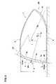
- FIG. 1is a perspective view of a golf club head showing an embodiment of the present invention
- FIG. 2is a front view of the club head of FIG. 1 ;
- FIG. 3is a plan view of the club head of FIG. 1 ;
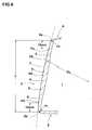
- FIG. 4is an enlarged cross sectional view along the line A-A of FIG. 3 ;
- FIG. 5is a horizontal cross sectional view of a face portion of the club head at a horizontal plane passing through the sweet spot;
- FIG. 6is a partially enlarged view of FIG. 4 ;
- FIG. 7is a graph showing a relationship between the Iy/Ix ratio and the Ry/Rx ratio
- FIGS. 8A to 8Care schematic plan views for illustrating the horizontal gear effect.
- FIGS. 9A and 9Bare cross sectional views for illustrating the vertical gear effect.
- FIGS. 1 to 4are perspective, front and plan views of a wood-type golf club head 1 according to an embodiment of the present invention, and an enlarged cross sectional view along the line A-A of FIG. 3 , respectively.
- the wood-type golf club head 1 in this embodimentcomprises a head body 1 a having a hollow structure, and a hosel portion 1 b which is disposed on a heel side of the body 1 a for inserting a shaft.
- the head body 1 aincludes a face portion 3 having a face 2 for hitting a golf ball on its front side, a crown portion 4 which extends from an upper edge 2 a of the face 2 and forming the upper surface of the head 1 , a sole portion 5 which extends from an lower edge 2 b of the face 2 and forming the bottom surface of the head 1 , and a side portion 6 which extends between the crown portion 4 and the sole portion 5 to connect them from a toe side edge 2 c of the face 2 to a heel side edge 2 d of the face 2 through a back face BF of the head 1 .
- the head body 1 ahas a hollow portion “i”.
- the hosel portion 1 bis disposed on a heel side of the crown portion 4 of the head body 1 a and has a cylindrical shaft inserting hole 7 to attach a shaft (not shown). Since the axial center line of the shaft inserting hole 7 substantially agrees with the axial center line CL of the shaft when the shaft is inserted into the hole 7 , it is used as the axial center line CL of the shaft when no shaft is attached to the club head 1 .
- the club head 1is kept in the standard state.
- standard stateof a golf club head as used herein denotes the state that, as shown in FIGS. 2 to 4 , golf club head 1 is placed on a horizontal plane HP in the state that the axial center line CL of a shaft is disposed in an optional vertical plane VP and is inclined at a prescribed lie angle ⁇ with respect to the horizontal plane HP, and the hitting face 2 is inclined at a prescribed loft angle ⁇ (real loft angle, hereinafter the same) given to the head 1 .
- the head 1 referred to hereinis in the standard state unless otherwise noted.
- the terms “prescribed lie angle ⁇ ” and “prescribed loft angle ⁇ ” as used hereindenote those previously given to the head 1 .
- the up-down direction and the height directiondenote those of the club head 1 in the standard state.
- the front-rear directiondenotes, when the head 1 in the standard state is viewed from above, namely in a plane view of the head 1 ( FIG. 3 ), a direction which is parallel to a perpendicular line N drawn from the club head's center of gravity G to the face 2 , in other words, a direction parallel to a line N connecting the center of gravity G and a sweet spot SS.
- a face 2 sideis the front and a back face BF side is the rear or back.
- the toe-heel direction of the club head 1denotes a direction parallel to the vertical plane VP defined above, in other words, a direction perpendicular to the front-rear direction, in the plan view of the head 1 in the standard state ( FIG. 3 ).
- the sweet spot SSis a point where a normal line N drawn to the face 2 from the center of gravity G of the head 1 intersects the face 2 .
- wood-type golf club headdoes not mean that the head is made of a woody material, but means golf club heads having a so-called wood-type head shape, e.g., driver (#1 wood), brassy (#2 wood), spoon (#3 wood), baffy (#4 wood) and cleek (#5 wood), and comprehends heads which are different from these heads in number or name, but have a shape approximately similar to these heads.
- the club head 1 in this embodimentis produced from a metallic material.
- the metallic materialare, for instance, a stainless steel, a marageing steel, a pure titanium, a titanium alloy, an aluminum alloy, and combinations of these metals.
- a nonmetallic materiale.g., fiber-reinforced resins and ionomers, may be used in a part of the club head 1 .
- the club head 1can be produced by joining a plurality of members or pieces (e.g., two to five pieces). The number of pieces is not particularly limited. Each member or piece is formed by various molding methods, e.g., casting, forging and pressing.
- the club head 1 of the present inventionhas a head volume of at least 400 cm 3 , especially at least 420 cm 3 , more especially at least 430 cm 3 .
- the “head volume”denotes the volume of a portion surrounded by the outer surface of head 1 whose shaft inserting hole 7 in the hosel portion is filled up.
- Such a large head volumewould provide a sense of ease to a player at the time of address, and it is also useful in improving the flight directionality since the moment of inertia or the depth of the center of gravity of the club head 1 can be increased.
- the volume of the club head 1is preferably at most 470 cm 3 , more preferably at most 460 cm 3 .
- the weight of club head 1is at least 180 g, especially at least 183 g, more especially at least 185 g, and it is at most 220 g, especially at most 215 g, more especially at most 213 g.
- the club head 1 of the present inventionhas a moment of inertia Ix of 4,000 to 5,900 g ⁇ cm 2 about the vertical axis passing through the center of gravity G.
- the club head 1 having such a large moment of inertia Ix about the vertical axiscan diminish the amount of rotation (twisting) of the head 1 about the vertical axis for toe or heel side off-center hits, whereby the amount of sidespin imparted to the ball by the horizontal gear effect is decreased to improve the straightness of flight.
- the moment of inertia Ix about the vertical axisis preferably at least 4,100 g ⁇ cm 2 , more preferably at least 4,200 g ⁇ cm 2 .
- the moment of inertia Ixis at most 5,800 g ⁇ cm 2 .
- Such a large moment of inertiacan be easily realized by increasing the head volume to fall within the above-mentioned range, by adjusting the thickness of respective portions of the head, and/or by additionally using a material having a high specific gravity, so as to distribute the weight to the perimeter of the club head.
- FIG. 5shows a horizontal cross section view passing through sweet spot SS of club head 1 in the standard state.
- the face 2 of the club head 1 in this embodimentis provided with a face bulge FB which is smoothly convex toward the front of the head 1 when the face is viewed from above.
- the face bulge FBis provided to substantially the entire region of the face 2 in the toe-heel direction.
- the convex curvature of this face bulge FBis formed not only at the section position shown in FIG. 5 , but also smoothly extends upward and downward.
- the club head 1 in this embodimenthas a large moment of inertia Ix about the vertical axis of 4,000 g ⁇ cm 2 or more as stated above, the horizontal gear effect is reduced and, therefore, the amount of sidespin is also reduced. If a face bulge BF having a small radius of curvature Rx is provided to such a head, a golf ball is struck out at an excessive deflection angle ⁇ on toe or heel hits (cf. FIG. 8C ), and does not curve back toward the intended line of flight due to a reduced sidespin. Thus, in the present invention, it is required that the radius of curvature Rx of the face bulge FB is 12 inches (about 30.48 cm) or more.
- the horizontal deflection angle ⁇ of the hit ball on toe or heel hitsis reduced to improve the flight direction performance.
- the radius of curvature Rx of the face bulge FBis preferably at least 13 inches, more preferably at least 14 inches.
- the club heads 1have a large moment of inertia Ix about the vertical axis, a slight horizontal gear effect still generates and it imparts a sidespin to the golf ball. Therefore, if the radius of curvature Rx of the face bulge FB is too large, the deflection angle ⁇ on a mishit may become excessively small, so it cannot compensate for the gear effect spin and the flight directionality may be deteriorated. Therefore, from such a point of view, it is required that the radius of curvature Rx of the face bulge FB is at most 25 inches (about 63.50 cm). The radius of curvature Rx is preferably at most 24 inches, more preferably at most 22 inches.
- the “radius of curvature Rx of the face bulge FB”is defined, for convenience's sake, as a radius of a single arc which passes through the following three points; a face toe side point Pt on the face 2 which is apart from the toe side edge 2 c of the face 2 toward the sweet spot SS by a distance of 20 mm in the toe-heel direction, a face heel side point Ph on the face 2 which is apart from the heel side edge 2 d of the face 2 toward the sweet spot SS by a distance of 20 mm in the toe-heel direction, and the sweet spot SS.
- the radius of curvature Rxis defined for the face in the state that the score lines or the like are filled.
- these edge positionsare the edges 2 c and 2 d.
- the toe side edge 2 c and the heel side edge 2 dare not clearly determined, they are defined as positions at which the actual radius of curvature “ra” of the face 2 reaches 20 mm for the first time when the actual radius “ra” is measured from the sweet spot SS toward the toe and heel sides.
- the ratio Rx/Ix of the radius of curvature Rx (inch) of the face bulge FB to the moment of inertia Ix (g ⁇ cm 2 ) about the vertical axisis at least 0.0028, especially at least 0.0030, more especially at least 0.0031, further especially at least 0.0033, still further especially at least 0.0037, and is at most 0.0050, especially at most 0.0045, more especially at most 0.0040.
- FIG. 4shows a vertical cross section view passing through the center of gravity G and the sweet spot SS of club head 1 in the standard state.
- FIG. 6shows an enlarged partial view of the face portion 3 in FIG. 4 .
- the face 2 of the club head 1 in this embodimentis provided with a face roll FR having a radius of curvature Ry which is smoothly convex toward the front of the head 1 when the face is viewed from the side.
- the face roll FRis provided to substantially the entire region of the face 2 from top to bottom.
- the convex curvature of this face roll FRis formed not only at the section position shown in FIG. 6 , but also smoothly extends toward both the toe and heel sides.
- the radius of curvature Ry of the face roll FRis set to 0.50 to 0.90 times the radius of curvature Rx of the face bulge FB.
- the radius of curvature Ry of the face rollis selected so that the Ry/Rx ratio falls within the range of 0.50 to 0.90.
- the flexural rigidity of the face portion 3is enhanced without increasing the thickness or the like of the face portion 3 by setting the radius of curvature Ry of the face roll FR to a value smaller than the radius of curvature Rx of the face bulge FB, thereby preventing the spring effect from excessively appearing.
- the flexural rigidity of the face portion 3can be enhanced by increasing the thickness of the face portion 3 , but the increase of the thickness is undesirable since the degree of freedom in weight distribution design is remarkably lowered.
- the Ry/Rx ratiois less than 0.50, the radius of curvature Ry of the face roll FR is excessively small as compared with that of the face bulge FB and, therefore, the face looks like it is protruding forwardly at the time of address and the sense of use is remarkably deteriorated.
- the launch angel ⁇ on high or low hitsis larger or smaller than the launch angle of a ball struck at sweet spot.
- the Ry/Rx ratiois preferably at least 0.55, more preferably at least 0.60.
- the Ry/Rx ratiois more than 0.90, the face roll FR is flattened, so an effect of enhancing the rigidity of the face portion 3 is not sufficiently obtained. As a result, the rebound property of the club head 1 tends to exceed an upper limit provided in golf rules, unless any measure such as thickening the face portion is taken. From such a point of view, the Ry/Rx ratio is preferably at most 0.85, more preferably at most 0.80.
- the “radius of curvature Ry of the face roll FR”is defined, for convenience's sake, as a radius of a single arc which passes through the following three points; a face upper side point Pu on the face 2 which is apart from the upper edge 2 a of the face 2 toward the downside by a distance of 10 mm in the vertical direction, a face downside point Pd on the face 2 which is apart from the lower edge 2 b of the face 2 toward the upper side by a distance of 10 mm in the vertical direction, and the sweet spot SS.
- the radius of curvature Ryis defined for the face in the state that the score lines 9 or the like are filled.
- edge positionsare the edges 2 a and 2 b.
- the upper edge 2 a and the lower edge 2 bare not clearly determined, they are defined as positions at which the actual radius of curvature “ra” of the face 2 reaches 20 mm for the first time, in the vertical cross section as shown in FIG. 6 , when the actual radius “ra” is measured from the sweet spot SS toward the upper and down sides.
- the radius of curvature Ry of the face roll FRis not particularly limited so long as it satisfies the above-mentioned Ry/Rx ratio condition.
- the change in launch angle ⁇ on high and low hitstends to become large as the radius of curvature Ry decreases. Therefore, it is preferable that the radius of curvature Ry is at least 8 inches, especially at least 9 inches, more especially at least 10 inches.
- the vertical gear effect on high and low hitsappears more strongly as the radius of curvature Ry increases, so the amount of backspin tends to be not stabilized to result in unstable flight distance. From such points of view, it is preferable that the radius of curvature Ry is at most 20 inches, especially at most 19 inches, more especially at most 17 inches.
- an excessive bending of the face portion 3 by impact of a ballis suppressed to control appearance of the spring effect within provisions of golf rules by adopting a small radius of curvature for the face roll FR.
- the radius of curvature of the face rollis small, there is a tendency that the launch angle ⁇ for high hits becomes large and the launch angle ⁇ for low hits becomes noticeably small (cf. FIG. 9A ). In particular, loss of flight distance is easy to occur at the time of low hits.
- the moment of inertia Iy about a horizontal axis extending through the center of gravity G in the toe-heel directionis set to a small value to deliberately increase the amount of rotation of the head about the horizontal axis for mishits.
- a relatively strong vertical gear effectappears for low hits to impart an increased amount of backspin to a ball, whereby even if the launch angle ⁇ is low, a large lift force is imparted to the ball to minimally suppress the lowering of the flight distance.
- the moment of inertia Iy about the horizontal axisis at most 5,900 g ⁇ cm 2 , especially at most 4,000 g ⁇ cm 2 , more especially at most 3,600 g ⁇ cm 2 .
- the moment of inertia Iy about the horizontal axisis too small, the amount of rotation of the head about the horizontal axis becomes excessively large for mishits, so the flight distance tends to be not stabilized.
- the moment of inertia Iyis at least 1,500 g ⁇ cm 2 , especially at least 1,800 g ⁇ cm 2 , more especially at least 2,000 g ⁇ cm 2 , further especially at least 3,000 g ⁇ cm 2 .
- the Ry/Iy ratio (inch/g ⁇ cm 2 ) of the radius of curvature Ry (inch) of the face roll to the moment of inertia Iy (g ⁇ cm 2 ) about the horizontal axisis at least 0.0030, especially at least 0.0035, more especially at least 0.0040, and is at most 0.0080, especially at most 0.0070, more especially at most 0.0060.
- the Iy/Ix ratio of the moment of inertia Iy about the horizontal axis to the moment of inertia Ix of the vertical axisis at least 0.30, especially at least 0.35, more especially at least 0.40, and is at most 0.80, especially at most 0.75, more especially at most 0.70. If the Iy/Ix ratio is less than 0.30, the flight directionality is improved, but there is a tendency that the vertical gear effect appears strongly in excess for high and low hits, so the launch angle ⁇ is not stabilized, thus resulting in unstable flight distance. On the other hand, if the Iy/Ix ratio is more than 0.80, the vertical gear effect on high and low hits is suppressed to stabilize the flight distance, but the flight directionality on toe and heel hits tends to deteriorate.
- the flight distance and the flight directionalityare further improved when the moment of inertia ratio Iy/Ix and the radius of curvature ratio Ry/Rx satisfy the following relationship: 1.0 ⁇ ( Ry/Rx )/( Iy/Ix ) ⁇ 2.0 If the ratio (Ry/Rx)/(Iy/Ix) is less than 1.0, the flight distance is easy to become unstable, and if it is more than 2.0, the flight directionality is easy to deteriorate.
- Wood-type golf club heads having a base structure shown in FIGS. 1 to 4were prepared according to the specifications shown in Table 1 and tested with respect to the flight distance and flight direction performances.
- the respective club headswere prepared by welding a plate-like face member “k” and a hollow head body member “m”, the boundary of which is shown in FIG. 1 by a chain line.
- the head body member “m”was prepared by precision casting of a Ti-6Al-4V alloy.
- the face member “k”was prepared by subjecting an ⁇ - ⁇ titanium alloy (Titanium Alloy “SP700HM” made by JFE Steel Corporation having a composition of Al: 4.0 to 5.0% by weight, V: 2.5 to 3.5% by weight, Mo: 1.8 to 2.2% by weight, Fe: 1.7 to 2.3% by weight, and Ti and unavoidable impurities: the rest) to machine work and press work to have a thick center portion and a thin peripheral portion.
- the head body member “m” and the face member “k”were joined by laser welding to give club heads having the following common specifications.
- the wall thickness of the head body memberwas partially changed so that the thickness of the side portion falls within the range of 0.5 to 1.5 mm and the thickness of the sole portion falls within the range of 0.7 to 2.0 mm.
- the face memberwas formed into a periphery-thin wall structure (cf. FIG. 4 ) having a center thick wall region 3 a with a similar shape to the shape of the face 2 formed by the peripheral edges 2 a to 2 d, a peripheral thin wall region 3 b and a transition portion 3 c between them, in which the difference in thickness between the thick wall region and the thin wall region was 1.0 mm, and the entire thickness was adjusted so that the CT value according to the Pendulum Test Protocol (test rules of the R & A) falls within the range of 250 ⁇ 20.
- the center of gravity and the moment of inertiawere adjusted.
- the testing methodsare as follows:
- test resultsare shown in Table 1 and FIG. 7 .
Landscapes
- Health & Medical Sciences (AREA)
- General Health & Medical Sciences (AREA)
- Physical Education & Sports Medicine (AREA)
- Life Sciences & Earth Sciences (AREA)
- Engineering & Computer Science (AREA)
- Wood Science & Technology (AREA)
- Golf Clubs (AREA)
Abstract
Description
1.0≦(Ry/Rx)/(Iy/Ix)≦2.0
wherein Rx is the radius of curvature of the face bulge (inch), Ry is the radius of curvature of the face roll (inch), Ix is the moment of inertia about the vertical axis (g·cm2), and Iy is the moment of inertia about the horizontal axis (g·cm2).
1.0≦(Ry/Rx)/(Iy/Ix)≦2.0
If the ratio (Ry/Rx)/(Iy/Ix) is less than 1.0, the flight distance is easy to become unstable, and if it is more than 2.0, the flight directionality is easy to deteriorate.
- Head weight: 200 g
- Head volume: 460 cm3
- Real loft angle: 11°
- Thickness of crown portion: 0.6 mm uniform thickness
- Height “h” of face: suitably varied within the range of 40 to 65 mm (cf.
FIG. 4 ) - Width FW of face: suitably varied within the range of 90 to 105 mm (cf.
FIG. 5 )
| TABLE 1 | |||||||
| Com. | Com. | ||||||
| Ex. 1 | Ex. 1 | Ex. 2 | Ex. 3 | Ex. 2 | Ex. 4 | Ex. 5 | |
| Moment of inertia Ix about vertical axis | 5600 | 5400 | 5400 | 5400 | 5400 | 5000 | 5000 |
| (g · cm2) | |||||||
| Radius of curvature Rx of face bulge | 25 | 20 | 20 | 20 | 20 | 20 | 20 |
| (inch) | |||||||
| Moment of inertia Iy about horizontal | 1500 | 2300 | 3200 | 3500 | 3500 | 4500 | 3500 |
| axis (g · cm2) | |||||||
| Radius of curvature Ry of face roll | 8 | 10 | 14 | 18 | 20 | 14 | 14 |
| (inch) | |||||||
| Ry/Rx ratio | 0.32 | 0.50 | 0.70 | 0.90 | 1.00 | 0.70 | 0.70 |
| Rx/Ix ratio | 0.0045 | 0.0037 | 0.0037 | 0.0037 | 0.0037 | 0.0040 | 0.0040 |
| Ry/Iy ratio | 0.0053 | 0.0043 | 0.0044 | 0.0051 | 0.0057 | 0.0031 | 0.0040 |
| Iy/Ix ratio | 0.27 | 0.43 | 0.59 | 0.65 | 0.65 | 0.90 | 0.70 |
| (Ry/Rx)/(Iy/Ix) ratio | 1.2 | 1.2 | 1.2 | 1.4 | 1.5 | 0.8 | 1.0 |
| Thickness of center thick wall region of | 3.3 | 3.3 | 3.4 | 3.5 | 3.7 | 3.4 | 3.4 |
| face portion (mm) | |||||||
| Flight distance (standard deviation A) | 23.7 | 19.1 | 17.3 | 17.6 | 21.1 | 20.2 | 17.9 |
| (yard) | |||||||
| Flight directionality (standard deviation | 14.1 | 12.7 | 11.8 | 11.2 | 12.0 | 14.1 | 12.4 |
| B of the amount of swerve) | |||||||
| (A + B)/2 | 37.8 | 31.8 | 29.1 | 28.8 | 33.1 | 34.3 | 30.3 |
| Ex. 6 | Ex. 7 | Ex. 8 | Ex. 9 | Ex. 10 | Ex. 11 | |
| Moment of inertia Ix about vertical axis | 5000 | 5400 | 5400 | 5000 | 5900 | 4000 |
| (g · cm2) | ||||||
| Radius of curvature Rx of face bulge | 20 | 20 | 15 | 25 | 18 | 25 |
| (inch) | ||||||
| Moment of inertia Iy about horizontal | 1750 | 1600 | 3200 | 3000 | 3600 | 2000 |
| axis (g · cm2) | ||||||
| Radius of curvature Ry of face roll | 14 | 13 | 10 | 18 | 10 | 18 |
| (inch) | ||||||
| Ry/Rx ratio | 0.70 | 0.65 | 0.67 | 0.72 | 0.56 | 0.72 |
| Rx/Ix ratio | 0.0040 | 0.0037 | 0.0028 | 0.0050 | 0.0031 | 0.0063 |
| Ry/Iy ratio | 0.0080 | 0.0081 | 0.0031 | 0.0060 | 0.0028 | 0.0090 |
| Iy/Ix ratio | 0.35 | 0.30 | 0.59 | 0.60 | 0.61 | 0.50 |
| (Ry/Rx)/(Iy/Ix) ratio | 2.0 | 2.2 | 1.1 | 1.2 | 0.9 | 1.4 |
| Thickness of center thick wall region of | 3.4 | 3.4 | 3.2 | 3.6 | 3.3 | 3.6 |
| face portion (mm) | ||||||
| Flight distance (standard deviation A) | 18.8 | 19.7 | 20.1 | 19.2 | 20.5 | 21.7 |
| (yard) | ||||||
| Flight directionality (standard deviation | 13.5 | 14.6 | 15.4 | 15.3 | 14.9 | 15.0 |
| B of the amount of swerve) | ||||||
| (A + B)/2 | 32.3 | 34.3 | 35.5 | 34.5 | 35.4 | 36.7 |
Claims (4)
1.0≦(Ry/Rx)/(Iy/Ix)≦2.0
Applications Claiming Priority (2)
| Application Number | Priority Date | Filing Date | Title |
|---|---|---|---|
| JP2008-105946 | 2008-04-15 | ||
| JP2008105946AJP5314319B2 (en) | 2008-04-15 | 2008-04-15 | Wood type golf club head |
Publications (2)
| Publication Number | Publication Date |
|---|---|
| US20090258727A1 US20090258727A1 (en) | 2009-10-15 |
| US8167737B2true US8167737B2 (en) | 2012-05-01 |
Family
ID=41164467
Family Applications (1)
| Application Number | Title | Priority Date | Filing Date |
|---|---|---|---|
| US12/352,643Active2029-08-17US8167737B2 (en) | 2008-04-15 | 2009-01-13 | Wood-type golf club head |
Country Status (2)
| Country | Link |
|---|---|
| US (1) | US8167737B2 (en) |
| JP (1) | JP5314319B2 (en) |
Cited By (21)
| Publication number | Priority date | Publication date | Assignee | Title |
|---|---|---|---|---|
| US20110263349A1 (en)* | 2010-03-31 | 2011-10-27 | O-Ta Precision Industry Co., Ltd. | Golf club head |
| US20120202615A1 (en)* | 2010-12-28 | 2012-08-09 | Taylor Made Golf Company, Inc. | Fairway wood center of gravity projection |
| US8393977B1 (en)* | 2010-09-10 | 2013-03-12 | Callaway Golf Company | Golf club |
| US20140148271A1 (en)* | 2011-08-10 | 2014-05-29 | Acushnet Company | Golf club head with multi-material face |
| US8979672B2 (en) | 2013-01-25 | 2015-03-17 | Dunlop Sports Co. Ltd. | Golf club head |
| US9168434B2 (en) | 2010-06-01 | 2015-10-27 | Taylor Made Golf Company, Inc. | Golf club head having a stress reducing feature with aperture |
| US9168428B2 (en) | 2010-06-01 | 2015-10-27 | Taylor Made Golf Company, Inc. | Hollow golf club head having sole stress reducing feature |
| US9174101B2 (en) | 2010-06-01 | 2015-11-03 | Taylor Made Golf Company, Inc. | Golf club head having a stress reducing feature |
| US9186560B2 (en) | 2010-12-28 | 2015-11-17 | Taylor Made Golf Company, Inc. | Golf club |
| US9707457B2 (en) | 2010-12-28 | 2017-07-18 | Taylor Made Golf Company, Inc. | Golf club |
| US9814944B1 (en) | 2016-06-30 | 2017-11-14 | Taylor Made Golf Company, Inc. | Golf club head |
| US9943734B2 (en) | 2004-11-08 | 2018-04-17 | Taylor Made Golf Company, Inc. | Golf club |
| US20190184246A1 (en)* | 2017-06-05 | 2019-06-20 | Taylor Made Golf Company, Inc. | Golf club heads |
| US10518143B1 (en) | 2018-06-19 | 2019-12-31 | Taylor Made Golf Company, Inc. | Golf club head |
| US10543405B2 (en) | 2016-06-30 | 2020-01-28 | Taylor Made Golf Company, Inc. | Golf club head |
| US10639524B2 (en) | 2010-12-28 | 2020-05-05 | Taylor Made Golf Company, Inc. | Golf club head |
| US10653926B2 (en) | 2018-07-23 | 2020-05-19 | Taylor Made Golf Company, Inc. | Golf club heads |
| US10870040B2 (en) | 2014-02-18 | 2020-12-22 | Karsten Manufacturing Corporation | Method of forming golf club head assembly |
| US11117026B2 (en) | 2013-03-14 | 2021-09-14 | Karsten Manufacturing Corporation | Golf club heads with optimized characteristics and related methods |
| US11406881B2 (en) | 2020-12-28 | 2022-08-09 | Taylor Made Golf Company, Inc. | Golf club heads |
| US11759685B2 (en) | 2020-12-28 | 2023-09-19 | Taylor Made Golf Company, Inc. | Golf club heads |
Families Citing this family (8)
| Publication number | Priority date | Publication date | Assignee | Title |
|---|---|---|---|---|
| JP5074841B2 (en)* | 2007-07-12 | 2012-11-14 | ダンロップスポーツ株式会社 | Wood type golf club head |
| JP2011212102A (en)* | 2010-03-31 | 2011-10-27 | Mrc Composite Products Co Ltd | Golf club head |
| JP5715520B2 (en)* | 2011-07-28 | 2015-05-07 | ダンロップスポーツ株式会社 | Golf club head and evaluation method thereof |
| JP2016512154A (en)* | 2013-03-14 | 2016-04-25 | カーステン マニュファクチュアリング コーポレーション | Golf club head with optimized properties and related methods |
| US10695621B2 (en)* | 2017-12-28 | 2020-06-30 | Taylor Made Golf Company, Inc. | Golf club head |
| US20230233911A1 (en)* | 2018-12-13 | 2023-07-27 | Acushnet Company | Golf club head with improved inertia performance |
| US11192005B2 (en)* | 2018-12-13 | 2021-12-07 | Acushnet Company | Golf club head with improved inertia performance |
| JP7600694B2 (en)* | 2021-01-13 | 2024-12-17 | 住友ゴム工業株式会社 | Golf Club Head |
Citations (16)
| Publication number | Priority date | Publication date | Assignee | Title |
|---|---|---|---|---|
| US3625518A (en)* | 1969-05-23 | 1971-12-07 | Karsten Solheim | Golf club head with complex curvature for the sole and/or the striking face |
| JPH0889603A (en) | 1994-09-28 | 1996-04-09 | Bridgestone Sports Co Ltd | Golf club head |
| US5681228A (en)* | 1995-11-16 | 1997-10-28 | Bridgestone Sports Co., Ltd. | Golf club head |
| JP2001161866A (en) | 1999-12-06 | 2001-06-19 | Sumitomo Rubber Ind Ltd | Golf club head |
| US6344002B1 (en)* | 1998-09-16 | 2002-02-05 | Bridgestone Sports Co., Ltd. | Wood club head |
| US6402639B1 (en)* | 1999-10-28 | 2002-06-11 | Mizuno Corporation | Metal wood club head |
| US6428426B1 (en)* | 2000-06-28 | 2002-08-06 | Callaway Golf Company | Golf club striking plate with variable bulge and roll |
| US6454664B1 (en)* | 2000-11-27 | 2002-09-24 | Acushnet Company | Golf club head with multi-radius face |
| US6458043B1 (en)* | 2001-04-18 | 2002-10-01 | Acushnet Company | Golf club head with multi-radius face |
| US6508722B1 (en)* | 2000-01-31 | 2003-01-21 | Acushnet Company | Golf club head and improved casting method therefor |
| US6964617B2 (en)* | 2004-04-19 | 2005-11-15 | Callaway Golf Company | Golf club head with gasket |
| US7059972B2 (en)* | 2000-05-15 | 2006-06-13 | The Yokohama Rubber Co., Ltd. | Golf club head |
| US7066830B2 (en)* | 2002-05-13 | 2006-06-27 | Michael W. Day | Golf club with improved head |
| US7147572B2 (en)* | 2002-11-28 | 2006-12-12 | Sri Sports Limited | Wood type golf club head |
| US7163468B2 (en)* | 2005-01-03 | 2007-01-16 | Callaway Golf Company | Golf club head |
| US20090191980A1 (en)* | 2007-12-21 | 2009-07-30 | Taylor Made Golf Company, Inc. | Golf club head |
Family Cites Families (2)
| Publication number | Priority date | Publication date | Assignee | Title |
|---|---|---|---|---|
| JP3554515B2 (en)* | 1999-12-17 | 2004-08-18 | 住友ゴム工業株式会社 | Wood type golf club head |
| JP2004261451A (en)* | 2003-03-03 | 2004-09-24 | Sumitomo Rubber Ind Ltd | Golf club head |
- 2008
- 2008-04-15JPJP2008105946Apatent/JP5314319B2/enactiveActive
- 2009
- 2009-01-13USUS12/352,643patent/US8167737B2/enactiveActive
Patent Citations (17)
| Publication number | Priority date | Publication date | Assignee | Title |
|---|---|---|---|---|
| US3625518A (en)* | 1969-05-23 | 1971-12-07 | Karsten Solheim | Golf club head with complex curvature for the sole and/or the striking face |
| JPH0889603A (en) | 1994-09-28 | 1996-04-09 | Bridgestone Sports Co Ltd | Golf club head |
| US5681228A (en)* | 1995-11-16 | 1997-10-28 | Bridgestone Sports Co., Ltd. | Golf club head |
| US6344002B1 (en)* | 1998-09-16 | 2002-02-05 | Bridgestone Sports Co., Ltd. | Wood club head |
| US6402639B1 (en)* | 1999-10-28 | 2002-06-11 | Mizuno Corporation | Metal wood club head |
| JP2001161866A (en) | 1999-12-06 | 2001-06-19 | Sumitomo Rubber Ind Ltd | Golf club head |
| US6508722B1 (en)* | 2000-01-31 | 2003-01-21 | Acushnet Company | Golf club head and improved casting method therefor |
| US7059972B2 (en)* | 2000-05-15 | 2006-06-13 | The Yokohama Rubber Co., Ltd. | Golf club head |
| US6428426B1 (en)* | 2000-06-28 | 2002-08-06 | Callaway Golf Company | Golf club striking plate with variable bulge and roll |
| US6454664B1 (en)* | 2000-11-27 | 2002-09-24 | Acushnet Company | Golf club head with multi-radius face |
| US6582322B2 (en)* | 2000-11-27 | 2003-06-24 | Acushnet Company | Golf club head with multi-radius face |
| US6458043B1 (en)* | 2001-04-18 | 2002-10-01 | Acushnet Company | Golf club head with multi-radius face |
| US7066830B2 (en)* | 2002-05-13 | 2006-06-27 | Michael W. Day | Golf club with improved head |
| US7147572B2 (en)* | 2002-11-28 | 2006-12-12 | Sri Sports Limited | Wood type golf club head |
| US6964617B2 (en)* | 2004-04-19 | 2005-11-15 | Callaway Golf Company | Golf club head with gasket |
| US7163468B2 (en)* | 2005-01-03 | 2007-01-16 | Callaway Golf Company | Golf club head |
| US20090191980A1 (en)* | 2007-12-21 | 2009-07-30 | Taylor Made Golf Company, Inc. | Golf club head |
Cited By (82)
| Publication number | Priority date | Publication date | Assignee | Title |
|---|---|---|---|---|
| US10610747B2 (en) | 2004-11-08 | 2020-04-07 | Taylor Made Golf Company, Inc. | Golf club |
| US9943734B2 (en) | 2004-11-08 | 2018-04-17 | Taylor Made Golf Company, Inc. | Golf club |
| US20110263349A1 (en)* | 2010-03-31 | 2011-10-27 | O-Ta Precision Industry Co., Ltd. | Golf club head |
| US9566479B2 (en) | 2010-06-01 | 2017-02-14 | Taylor Made Golf Company, Inc. | Golf club head having sole stress reducing feature |
| US9610483B2 (en) | 2010-06-01 | 2017-04-04 | Taylor Made Golf Company, Inc | Iron-type golf club head having a sole stress reducing feature |
| US11865416B2 (en) | 2010-06-01 | 2024-01-09 | Taylor Made Golf Company, Inc. | Golf club head having a shaft connection system socket |
| US11771964B2 (en) | 2010-06-01 | 2023-10-03 | Taylor Made Golf Company, Inc. | Multi-material iron-type golf club head |
| US9168434B2 (en) | 2010-06-01 | 2015-10-27 | Taylor Made Golf Company, Inc. | Golf club head having a stress reducing feature with aperture |
| US9168428B2 (en) | 2010-06-01 | 2015-10-27 | Taylor Made Golf Company, Inc. | Hollow golf club head having sole stress reducing feature |
| US9174101B2 (en) | 2010-06-01 | 2015-11-03 | Taylor Made Golf Company, Inc. | Golf club head having a stress reducing feature |
| US11478685B2 (en) | 2010-06-01 | 2022-10-25 | Taylor Made Golf Company, Inc. | Iron-type golf club head |
| US11364421B2 (en) | 2010-06-01 | 2022-06-21 | Taylor Made Golf Company, Inc. | Golf club head having a shaft connection system socket |
| US9265993B2 (en) | 2010-06-01 | 2016-02-23 | Taylor Made Golf Company, Inc | Hollow golf club head having crown stress reducing feature |
| US11351425B2 (en) | 2010-06-01 | 2022-06-07 | Taylor Made Golf Company, Inc. | Multi-material iron-type golf club head |
| US10300350B2 (en) | 2010-06-01 | 2019-05-28 | Taylor Made Golf Company, Inc. | Golf club having sole stress reducing feature |
| US9610482B2 (en) | 2010-06-01 | 2017-04-04 | Taylor Made Golf Company, Inc | Golf club head having a stress reducing feature with aperture |
| US12042702B2 (en) | 2010-06-01 | 2024-07-23 | Taylor Made Golf Company, Inc. | Iron-type golf club head |
| US9656131B2 (en) | 2010-06-01 | 2017-05-23 | Taylor Made Golf Company, Inc. | Golf club head having a stress reducing feature and shaft connection system socket |
| US12296238B2 (en) | 2010-06-01 | 2025-05-13 | Taylor Made Golf Company, Inc. | Multi-material iron-type golf club head |
| US11045696B2 (en) | 2010-06-01 | 2021-06-29 | Taylor Made Golf Company, Inc. | Iron-type golf club head |
| US10843050B2 (en) | 2010-06-01 | 2020-11-24 | Taylor Made Golf Company, Inc. | Multi-material iron-type golf club head |
| US10792542B2 (en) | 2010-06-01 | 2020-10-06 | Taylor Made Golf Company, Inc | Golf club head having a stress reducing feature and shaft connection system socket |
| US10369429B2 (en) | 2010-06-01 | 2019-08-06 | Taylor Made Golf Company, Inc. | Golf club head having a stress reducing feature and shaft connection system socket |
| US9950222B2 (en) | 2010-06-01 | 2018-04-24 | Taylor Made Golf Company, Inc. | Golf club having sole stress reducing feature |
| US9950223B2 (en) | 2010-06-01 | 2018-04-24 | Taylor Made Golf Company, Inc. | Golf club head having a stress reducing feature with aperture |
| US9956460B2 (en) | 2010-06-01 | 2018-05-01 | Taylor Made Golf Company, Inc | Golf club head having a stress reducing feature and shaft connection system socket |
| US12357883B2 (en) | 2010-06-01 | 2025-07-15 | Taylor Made Golf Company, Inc. | Golf club head having a shaft connection system socket |
| US10245485B2 (en) | 2010-06-01 | 2019-04-02 | Taylor Made Golf Company Inc. | Golf club head having a stress reducing feature with aperture |
| US10556160B2 (en) | 2010-06-01 | 2020-02-11 | Taylor Made Golf Company, Inc. | Golf club head having a stress reducing feature with aperture |
| US8393977B1 (en)* | 2010-09-10 | 2013-03-12 | Callaway Golf Company | Golf club |
| US11202943B2 (en) | 2010-12-28 | 2021-12-21 | Taylor Made Golf Company, Inc. | Golf club head |
| US9700769B2 (en) | 2010-12-28 | 2017-07-11 | Taylor Made Golf Company, Inc. | Fairway wood center of gravity projection |
| US20120202615A1 (en)* | 2010-12-28 | 2012-08-09 | Taylor Made Golf Company, Inc. | Fairway wood center of gravity projection |
| US8900069B2 (en)* | 2010-12-28 | 2014-12-02 | Taylor Made Golf Company, Inc. | Fairway wood center of gravity projection |
| US10434384B2 (en) | 2010-12-28 | 2019-10-08 | Taylor Made Golf Company, Inc. | Golf club head |
| US8956240B2 (en) | 2010-12-28 | 2015-02-17 | Taylor Made Golf Company, Inc. | Fairway wood center of gravity projection |
| US11654336B2 (en) | 2010-12-28 | 2023-05-23 | Taylor Made Golf Company, Inc. | Golf club head |
| US10478679B2 (en) | 2010-12-28 | 2019-11-19 | Taylor Made Golf Company, Inc. | Golf club head |
| US9186560B2 (en) | 2010-12-28 | 2015-11-17 | Taylor Made Golf Company, Inc. | Golf club |
| US9211447B2 (en) | 2010-12-28 | 2015-12-15 | Taylor Made Golf Company, Inc. | Golf club |
| US10252119B2 (en) | 2010-12-28 | 2019-04-09 | Taylor Made Golf Company, Inc. | Golf club |
| US11298599B2 (en) | 2010-12-28 | 2022-04-12 | Taylor Made Golf Company, Inc. | Golf club head |
| US10603555B2 (en) | 2010-12-28 | 2020-03-31 | Taylor Made Golf Company, Inc. | Golf club head |
| US9700763B2 (en) | 2010-12-28 | 2017-07-11 | Taylor Made Golf Company, Inc. | Golf club |
| US10639524B2 (en) | 2010-12-28 | 2020-05-05 | Taylor Made Golf Company, Inc. | Golf club head |
| US11148021B2 (en) | 2010-12-28 | 2021-10-19 | Taylor Made Golf Company, Inc. | Golf club head |
| US10974102B2 (en) | 2010-12-28 | 2021-04-13 | Taylor Made Golf Company, Inc. | Golf club head |
| US9707457B2 (en) | 2010-12-28 | 2017-07-18 | Taylor Made Golf Company, Inc. | Golf club |
| US10905929B2 (en) | 2010-12-28 | 2021-02-02 | Taylor Made Golf Company, Inc. | Golf club head |
| US10898764B2 (en) | 2010-12-28 | 2021-01-26 | Taylor Made Golf Company, Inc. | Golf club head |
| US20140148271A1 (en)* | 2011-08-10 | 2014-05-29 | Acushnet Company | Golf club head with multi-material face |
| US8979672B2 (en) | 2013-01-25 | 2015-03-17 | Dunlop Sports Co. Ltd. | Golf club head |
| US9561409B2 (en) | 2013-01-25 | 2017-02-07 | Dunlop Sports Co. Ltd. | Golf club head |
| US9981166B2 (en) | 2013-01-25 | 2018-05-29 | Dunlop Sports Co. Ltd. | Golf club head |
| US11117026B2 (en) | 2013-03-14 | 2021-09-14 | Karsten Manufacturing Corporation | Golf club heads with optimized characteristics and related methods |
| US12220619B2 (en) | 2013-03-14 | 2025-02-11 | Karsten Manufacturing Corporation | Golf club heads with optimized characteristics |
| US11554299B2 (en) | 2013-03-14 | 2023-01-17 | Karsten Manufacturing Corporation | Golf club heads with optimized characteristics and related methods |
| US11426639B2 (en) | 2013-12-31 | 2022-08-30 | Taylor Made Golf Company, Inc. | Golf club |
| US10870040B2 (en) | 2014-02-18 | 2020-12-22 | Karsten Manufacturing Corporation | Method of forming golf club head assembly |
| US11752400B2 (en) | 2014-02-18 | 2023-09-12 | Karsten Manufacturing Corporation | Method of forming golf club head assembly |
| US11691054B2 (en) | 2016-06-30 | 2023-07-04 | Taylor Made Golf Company, Inc. | Golf club head |
| US10265586B2 (en) | 2016-06-30 | 2019-04-23 | Taylor Made Golf Company, Inc. | Golf club head |
| US10543405B2 (en) | 2016-06-30 | 2020-01-28 | Taylor Made Golf Company, Inc. | Golf club head |
| US11130024B2 (en) | 2016-06-30 | 2021-09-28 | Taylor Made Golf Company, Inc. | Golf club head |
| US10265587B2 (en) | 2016-06-30 | 2019-04-23 | Taylor Made Golf Company, Inc. | Golf club head |
| US10881916B2 (en) | 2016-06-30 | 2021-01-05 | Taylor Made Golf Company, Inc. | Golf club head |
| US10556157B2 (en) | 2016-06-30 | 2020-02-11 | Taylor Made Golf Company, Inc. | Golf club head |
| US9814944B1 (en) | 2016-06-30 | 2017-11-14 | Taylor Made Golf Company, Inc. | Golf club head |
| US10463926B2 (en) | 2016-06-30 | 2019-11-05 | Taylor Made Golf Company, Inc. | Golf club head |
| US10449423B2 (en) | 2016-06-30 | 2019-10-22 | Taylor Made Golf Company, Inc. | Golf club head |
| US10874922B2 (en)* | 2017-06-05 | 2020-12-29 | Taylor Made Golf Company, Inc. | Golf club heads |
| US20190184246A1 (en)* | 2017-06-05 | 2019-06-20 | Taylor Made Golf Company, Inc. | Golf club heads |
| US10518143B1 (en) | 2018-06-19 | 2019-12-31 | Taylor Made Golf Company, Inc. | Golf club head |
| US10960277B2 (en) | 2018-06-19 | 2021-03-30 | Taylor Made Golf Company, Inc. | Golf club head |
| US11400350B2 (en) | 2018-07-23 | 2022-08-02 | Taylor Made Golf Company, Inc. | Golf club heads |
| US11771963B2 (en) | 2018-07-23 | 2023-10-03 | Taylor Made Golf Company, Inc. | Golf club heads |
| US11013965B2 (en) | 2018-07-23 | 2021-05-25 | Taylor Made Golf Company, Inc. | Golf club heads |
| US10653926B2 (en) | 2018-07-23 | 2020-05-19 | Taylor Made Golf Company, Inc. | Golf club heads |
| US11975248B2 (en) | 2020-12-28 | 2024-05-07 | Taylor Made Golf Company, Inc. | Golf club heads |
| US11759685B2 (en) | 2020-12-28 | 2023-09-19 | Taylor Made Golf Company, Inc. | Golf club heads |
| US11406881B2 (en) | 2020-12-28 | 2022-08-09 | Taylor Made Golf Company, Inc. | Golf club heads |
| US12390703B2 (en) | 2020-12-28 | 2025-08-19 | Taylor Made Golf Company, Inc. | Golf club heads |
Also Published As
| Publication number | Publication date |
|---|---|
| JP2009254518A (en) | 2009-11-05 |
| US20090258727A1 (en) | 2009-10-15 |
| JP5314319B2 (en) | 2013-10-16 |
Similar Documents
| Publication | Publication Date | Title |
|---|---|---|
| US8167737B2 (en) | Wood-type golf club head | |
| US7857713B2 (en) | Wood-type golf club head | |
| US20220305355A1 (en) | Golf clubs and golf club heads having a configured shape | |
| US8727908B2 (en) | Golf club head | |
| US7682263B2 (en) | Golf club head | |
| US7749103B2 (en) | Golf club head | |
| US6623374B1 (en) | Golf club head and set of golf clubs | |
| JP5181052B2 (en) | Golf club set | |
| US7435189B2 (en) | Iron-type golf club head | |
| JP4423435B2 (en) | Golf club head | |
| US7500924B2 (en) | Golf club head | |
| US7993214B2 (en) | Golf club head | |
| US7766765B2 (en) | Wood-type golf club head | |
| CN101161315B (en) | Golf club | |
| US8038546B2 (en) | Wood-type golf club head | |
| US20040048682A1 (en) | Golf club head | |
| US7641570B2 (en) | Golf club head | |
| US20080113825A1 (en) | Golf club head | |
| JP5087328B2 (en) | Wood type golf club head | |
| JP2008253564A (en) | Golf club head | |
| US20090017938A1 (en) | Wood-type golf club head | |
| JP2012095855A (en) | Golf club | |
| US10688353B2 (en) | Iron-type golf club head | |
| US20070298906A1 (en) | Golf club head | |
| US8371955B2 (en) | Wood-type golf club set |
Legal Events
| Date | Code | Title | Description |
|---|---|---|---|
| AS | Assignment | Owner name:SRI SPORTS LIMITED, JAPAN Free format text:ASSIGNMENT OF ASSIGNORS INTEREST;ASSIGNOR:OYAMA, HITOSHI;REEL/FRAME:022108/0313 Effective date:20081225 | |
| STCF | Information on status: patent grant | Free format text:PATENTED CASE | |
| FEPP | Fee payment procedure | Free format text:PAYOR NUMBER ASSIGNED (ORIGINAL EVENT CODE: ASPN); ENTITY STATUS OF PATENT OWNER: LARGE ENTITY | |
| FPAY | Fee payment | Year of fee payment:4 | |
| AS | Assignment | Owner name:DUNLOP SPORTS CO. LTD., JAPAN Free format text:CHANGE OF NAME;ASSIGNOR:SRI SPORTS LIMITED;REEL/FRAME:045932/0024 Effective date:20120501 | |
| AS | Assignment | Owner name:SUMITOMO RUBBER INDUSTRIES, LTD., JAPAN Free format text:MERGER;ASSIGNOR:DUNLOP SPORTS CO. LTD.;REEL/FRAME:045959/0204 Effective date:20180116 | |
| MAFP | Maintenance fee payment | Free format text:PAYMENT OF MAINTENANCE FEE, 8TH YEAR, LARGE ENTITY (ORIGINAL EVENT CODE: M1552); ENTITY STATUS OF PATENT OWNER: LARGE ENTITY Year of fee payment:8 | |
| MAFP | Maintenance fee payment | Free format text:PAYMENT OF MAINTENANCE FEE, 12TH YEAR, LARGE ENTITY (ORIGINAL EVENT CODE: M1553); ENTITY STATUS OF PATENT OWNER: LARGE ENTITY Year of fee payment:12 |