US8167735B2 - Golf club with removable components - Google Patents
Golf club with removable componentsDownload PDFInfo
- Publication number
- US8167735B2 US8167735B2US13/223,535US201113223535AUS8167735B2US 8167735 B2US8167735 B2US 8167735B2US 201113223535 AUS201113223535 AUS 201113223535AUS 8167735 B2US8167735 B2US 8167735B2
- Authority
- US
- United States
- Prior art keywords
- sleeve
- shaft
- cap
- golf club
- hosel
- Prior art date
- Legal status (The legal status is an assumption and is not a legal conclusion. Google has not performed a legal analysis and makes no representation as to the accuracy of the status listed.)
- Active
Links
- 239000000463materialSubstances0.000claimsdescription13
- 230000013011matingEffects0.000claimsdescription13
- 239000007769metal materialSubstances0.000claimsdescription10
- 229910001069Ti alloyInorganic materials0.000claimsdescription8
- 229910052751metalInorganic materials0.000claimsdescription7
- 239000002184metalSubstances0.000claimsdescription7
- 239000010935stainless steelSubstances0.000claimsdescription5
- 229910001220stainless steelInorganic materials0.000claimsdescription5
- RTAQQCXQSZGOHL-UHFFFAOYSA-NTitaniumChemical compound[Ti]RTAQQCXQSZGOHL-UHFFFAOYSA-N0.000claimsdescription4
- 239000010936titaniumSubstances0.000claimsdescription4
- 229910052719titaniumInorganic materials0.000claimsdescription4
- 229910000838Al alloyInorganic materials0.000claimsdescription3
- 239000002131composite materialSubstances0.000claimsdescription3
- 229910052782aluminiumInorganic materials0.000claimsdescription2
- XAGFODPZIPBFFR-UHFFFAOYSA-NaluminiumChemical compound[Al]XAGFODPZIPBFFR-UHFFFAOYSA-N0.000claimsdescription2
- 239000007770graphite materialSubstances0.000claimsdescription2
- 239000011248coating agentSubstances0.000claims1
- 238000000576coating methodMethods0.000claims1
- OKTJSMMVPCPJKN-UHFFFAOYSA-NCarbonChemical compound[C]OKTJSMMVPCPJKN-UHFFFAOYSA-N0.000description4
- 239000008188pelletSubstances0.000description4
- 230000008878couplingEffects0.000description3
- 238000010168coupling processMethods0.000description3
- 238000005859coupling reactionMethods0.000description3
- 239000004593EpoxySubstances0.000description2
- 239000000853adhesiveSubstances0.000description2
- 230000001070adhesive effectEffects0.000description2
- 229910052799carbonInorganic materials0.000description2
- 229910002804graphiteInorganic materials0.000description2
- 239000010439graphiteSubstances0.000description2
- 238000000034methodMethods0.000description2
- 229910000851Alloy steelInorganic materials0.000description1
- FYYHWMGAXLPEAU-UHFFFAOYSA-NMagnesiumChemical compound[Mg]FYYHWMGAXLPEAU-UHFFFAOYSA-N0.000description1
- 230000002411adverseEffects0.000description1
- 230000008859changeEffects0.000description1
- 230000006835compressionEffects0.000description1
- 238000007906compressionMethods0.000description1
- 238000011161developmentMethods0.000description1
- 230000005484gravityEffects0.000description1
- 239000011777magnesiumSubstances0.000description1
- 229910052749magnesiumInorganic materials0.000description1
- 238000012986modificationMethods0.000description1
- 230000004048modificationEffects0.000description1
- 230000002265preventionEffects0.000description1
- 230000008569processEffects0.000description1
- 238000011160researchMethods0.000description1
- 238000006467substitution reactionMethods0.000description1
- 239000012815thermoplastic materialSubstances0.000description1
- 239000002023woodSubstances0.000description1
Images


Classifications
- A—HUMAN NECESSITIES
- A63—SPORTS; GAMES; AMUSEMENTS
- A63B—APPARATUS FOR PHYSICAL TRAINING, GYMNASTICS, SWIMMING, CLIMBING, OR FENCING; BALL GAMES; TRAINING EQUIPMENT
- A63B53/00—Golf clubs
- A63B53/02—Joint structures between the head and the shaft
- A—HUMAN NECESSITIES
- A63—SPORTS; GAMES; AMUSEMENTS
- A63B—APPARATUS FOR PHYSICAL TRAINING, GYMNASTICS, SWIMMING, CLIMBING, OR FENCING; BALL GAMES; TRAINING EQUIPMENT
- A63B2210/00—Space saving
- A63B2210/50—Size reducing arrangements for stowing or transport
Definitions
- the present inventionrelates to a golf club having an improved connection for interchanging components.
- golfersIn order to improve their game, golfers often customize their equipment to fit their particular swing. Golf equipment manufacturers have responded by increasing the variety of clubs available to golfers. For example, a particular model of a driver-type golf club may be offered in several different loft angles and lie angles to suit a particular golfer's needs. In addition, golfers can choose shafts, whether metal or graphite, and adjust the length of the shaft to suit their swing. Golf clubs that allow shaft and club head components to be easily interchanged facilitate this customization process.
- the Wheeler patentdiscloses a putter having a grip and a putter head, both of which are detachable from a shaft.
- Fastening membersprovided on the upper and lower ends of the shaft, have internal threads, which engage the external threads provided on both the lower end of the grip and the upper end of the putter head shank to secure these components to the shaft.
- the lower portion of the shaftfurther includes a flange, which contacts the upper end of the putter head shank, when the putter head is coupled to the shaft.
- the Walker patentdiscloses a golf club in which the club head is secured to the shaft by a coupling rod and a quick release pin.
- the upper end of the coupling rodhas external threads that and engage the internal threads formed in the lower portion of the shaft.
- the lower end of the coupling rodwhich is inserted into the hosel of the club head, has diametric apertures that align with diametric apertures in the hosel to receive the quick release pin.
- the Roark patentdiscloses a golf club with a quick release for detaching a club head from a shaft.
- the quick releaseis a two-piece connector including a lower connector, which is secured in the hosel of the club head, and an upper connector, which is secured in the lower portion of the shaft.
- the upper connectorhas a pin and a ball catch that protrude radially outward from the lower end of the upper connector.
- the upper end of the lower connectorhas a slot formed therein for receiving the upper connector pin, and a separate hole for receiving the ball catch. When the shaft is coupled to the club head, the lower connector hole retains the ball catch to secure the shaft to the club head.
- the Burrows applicationsdisclose a temporary connection that includes an adapter insert, a socket member, and a mechanical fastener.
- the adapter insertwhich is mounted on a shaft, includes a thrust flange.
- the socket memberwhich is mounted on the other golf club component (e.g., a club head), includes a thrust seat for seated reception of the thrust flange.
- the mechanical fastenere.g., a compression nut or a lock bolt
- the prior art temporary head-shaft connectionshave several disadvantages. These connections typically add excessive weight to the club head, which affects the playability characteristics of the golf club. A change in the overall weight of a golf club alters the center of gravity and moments of inertias of the club head. Thus, a golf club with a shaft permanently affixed to a club head would have inherently different characteristics than a trial golf club that uses a prior art temporary connection to combine the same shaft and club head. In addition, many of these prior art connections are cumbersome to use. Some designs require the connection device to be accessed from the bottom of the club head, others from the top, with different tools and procedures for each.
- the present inventionprovides an improved club head-shaft connection that couples golf club heads and shafts in a manner that does not adversely affect the playability of the resulting golf club.
- the hosel of the club headis itself provided with a threaded portion and a rotation prevention portion. Therefore, fewer components are required for assembly, which reduces the overall weight of the connection and enables more discretionary weight to be distributed elsewhere in the club head.
- a golf club having removable componentsincludes a club head, a shaft, and a connection assembly.
- the club headincludes a body having a hosel.
- the hoselincludes an upper treaded portion and a lower portion.
- the upper threaded portion of the hoselhas a plurality of threads, which provide the upper threaded portion with a threaded cross-section.
- the lower portion of the hoselhas a multi-faceted cross-section.
- the shafthas a tip end and a butt end.
- the connection assemblyincludes a sleeve mounted on the tip end of the shaft and a screw-cap.
- the sleevehas a body that includes a top section and a lower section.
- the lower sectionhas a multi-faceted surface for engaging the lower portion of the hosel.
- the sleevefurther includes an aperture for receiving the tip end of the shaft.
- the screw-caphas a body with a central aperture. The screw cap is mounted over the sleeve.
- the screw-cap bodyhas an upper area and a threaded area, the latter of which capable of engaging the upper threaded portion of the hosel of the club head for removably securing the shaft to the club head.
- a golf clubhas a club head that includes a face cup and an aft-body.
- the face cupcomprised of a metal material and including a striking face and a hosel.
- the hoselhaving an upper threaded portion and a lower portion.
- the upper threaded portion of the hoselhas a plurality of threads thereon.
- the lower portionhas a tapered, faceted cross-section.
- the golf clubfurther includes a connection assembly comprising a sleeve and a screw-cap.
- the sleevewhich is mounted on the tip end of a shaft, includes a body having a top section and a lower section.
- the lower section of the sleevehas a tapered, multi-faceted surface for engaging the lower portion of the hosel.
- the sleevefurther includes an aperture for receiving the tip end of the shaft.
- the screw-capincludes a body with a central aperture, the screw cap mounted over the sleeve, the body of the screw-cap having an upper area and a threaded area, the threaded area capable of engaging the upper threaded portion of the hosel of the club head for removably securing the shaft to the club head.
- the lower section of the sleevehas three faceted surfaces. Once fully inserted into the hosel, the three sides of the sleeve will make contact with three mating surfaces designed in the lower portion of the hosel. Three sides are preferred to stop rotation both axially and around a pivot axis that is created when fewer than three contact points are achieved.
- the screw-capWhen the screw-cap is tightened down on the sleeve, the screw-cap forces the multi-faceted lower section of the sleeve against the mating contact surfaces of the lower portion of the hosel of the golf club head, and all rotation is mechanically prohibited.
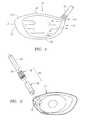
- FIG. 1is a front plan view of a golf club in accordance with the present invention.
- FIG. 2is an exploded top perspective view of the golf club of FIG. 1 illustrating the various components, including a face cup portion of a club head, a shaft, and the connection assembly, which includes a sleeve and a screw-cap.
- FIG. 3is perspective view of the golf club of FIG. 2 in an assembled state.
- FIG. 4is a cross-sectional view taken generally along the line 4 - 4 of FIG. 3 .
- FIG. 5is an enlarged cross-sectional view of a golf club shaft attached via the connection assembly to a hosel of a club head.
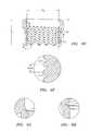
- FIG. 6Ais a top plan view of a face cup of a club head.
- FIG. 6Bis a cross-sectional view taken generally along the line A-A of FIG. 6A .
- FIG. 6Cis a cross-sectional view taken generally along the line B-B of FIG. 6B .
- FIG. 6Dis an enlarged sectional view taken along circle C of FIG. 6B .
- FIGS. 6E-6Hare enlarged sectional views showing greater details of an upper threaded portion of the hosel.
- FIG. 7Ais a plan view of a sleeve.
- FIG. 7Bis a cross-sectional view taken generally along the line A-A of FIG. 7A .
- FIG. 7Cis an enlarged sectional view taken generally along rectangle B of FIG. 7B .
- FIG. 7Dis an enlarged sectional view taken generally along circle C of FIG. 7B .
- FIG. 7Eis an enlarged view taken generally along circle G of FIG. 7A .
- FIG. 7Fis a cross-sectional view taken generally along the line H-H of FIG. 7A .
- FIG. 8Ais a plan view of a screw-cap.
- FIG. 8Bis a top plan view of the screw-cap of FIG. 8A .
- FIG. 8Cis a cross-sectional view taken generally along the line A-A of FIG. 8B .
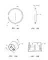
- FIG. 9Ais a plan view of a locking ring, which may be used in the connection assembly.
- FIG. 9Bis a cross-sectional view taken generally long the line A-A of FIG. 9A .
- FIG. 10Ais a perspective view of a ferrule, which may be used in the connection assembly.
- FIG. 10Bis a cross sectional view taken generally along the line A-A of FIG. 10A .
- FIG. 11Ais a plan view of a screw-cap with a polymeric patch.
- FIG. 11Bis a plan view of a screw-cap with a polymeric strip.
- FIG. 11Cis a plan view of a screw-cap with a polymeric pellet.
- a golf clubis generally designated 20 .
- Golf club 20has a club head 22 and a shaft 24 that is coupled to club head 22 .
- Club head 22is preferably a wood-type golf club head, such as a driver, a fairway wood, or even a hybrid iron-wood-type club, but may also be an iron-type club head.
- Club head 22includes a body 26 having a striking face 28 , a crown portion 30 , a sole portion 32 , a heel end 34 and a toe end 36 .
- Striking face 28generally extends along the front of club head 22 from heel end 34 to toe end 36 .
- Body 26is preferably composed of a metallic material, such as titanium, titanium alloy, stainless steel, or the like.
- body 26may be composed of multiple materials, such as a metal face cup 27 attached to an aft-body composed of a different material, such as a carbon composite material, or a stainless steel body with a carbon composite crown.
- Body 26preferably has a hollow interior and includes a hosel 38 for receiving shaft 24 .
- hosel 38is provided in cup face 27 .
- Hosel 38is preferably an internal hosel that extends into body 26 with an opening 40 in crown portion 30 .
- club head 22may be provided with an external hosel (not shown) rather than an internal one.
- Shaft 24is preferably composed of a graphite material, however, it may be composed of a metallic material, such as stainless steel or titanium. Alternatively, shaft 24 may be composed of a hybrid of graphite and metal. Shaft 24 is coupled to club head 22 using a connection assembly 44 that provides for easy assembly, disassembly and reassembly, thereby facilitating customization of golf club 20 .
- connection assembly 44preferably comprises a sleeve 46 and a screw-cap 48 .
- Connection assembly 44cooperates with hosel 38 of club head 22 to secure shaft 24 to club head 22 .
- Sleeve 46is mounted on a tip end 50 of shaft 24 .
- Shaft 24 with sleeve 46 mounted thereonis then inserted in hosel 38 of club head 22 .
- Screw-cap 48secures sleeve 46 to hosel 38 to retain shaft 24 in connection with club head 22 .
- hosel 38is preferably integrally formed with the body of club head 22 .
- club head 22 including hosel 38may be cast of a suitable metal material, such as titanium alloys, steel alloys, magnesium and aluminum.
- Hosel 38preferably has a main opening 58 for receiving a portion of sleeve 46 and shaft 24 .
- Main opening 58preferably has a depth L D of at least 1.000 inch, for example 1.065 inch.
- Hosel 38includes an upper threaded portion 60 and a lower portion 62 .
- Upper threaded portion 60includes a plurality of threads 64 , which provide upper threaded portion 60 with a threaded cross-section. As best illustrated in FIGS. 6E-6H , upper threaded portion 60 preferably has a length L U in the range of 0.350 inch to 0.500 inch. The diameter D U at a top end of upper threaded portion 60 is preferably 0.580 inch.
- the plurality of threads 64 provided in upper threaded portion 60preferably includes between one and ten threads, and more preferably between three and eight threads. In one embodiment of the invention, there are five threads 64 in upper threaded portion 60 .
- Threads 64preferably have a pitch in the range of six and thirty-two, more preferably between eighteen and twenty-eight, and even more preferably between twenty-four and twenty-eight. Threads 64 preferably have a pitch diameter PD in the range of 0.250 inch to 0.750 inch, more preferably in the range of 0.420 inch to 0.630 inch, and even more preferably between 0.530 inch and 0.570 inch.
- Lower portion 62 of hosel 38has a faceted cross-section, which is best illustrated in FIG. 6C .
- lower portion 62has at least three facets, planar surfaces 66 , with a curved region provided between adjacent planar surfaces 66 .
- lower portion 62tapers from proximate upper threaded portion 60 to the bottom of hosel 36 .
- lower portion 62may taper from a diameter of 0.517 inch proximate upper threaded portion 60 to a diameter D B of 0.312 inch proximate its bottom end. The taper of lower portion 62 ensures a snug fit between sleeve 46 and hosel 38 , when shaft 24 is fully secured to club head 22 .
- Sleeve 46which is best illustrated in FIGS. 7A-7F , has an aperture 68 formed in an upper end 69 thereof for receiving tip end 50 of shaft 24 .
- Sleeve 46is fixedly secured to shaft 24 using an adhesive, such as epoxy.
- Sleeve 46is preferably comprised of a metal material, such as titanium alloys and aluminum alloys.
- Sleeve 46which preferably has an overall length L S of at least 1.500 inches, includes a body having a top section 70 and a lower section 72 .
- Top section 70has an aperture 68 formed therein.
- Aperture 68has a diameter D A that complements the outer diameter of tip end 50 of shaft 24 .
- Depth L A of aperture 68is preferably sufficient to receive at least 1.000 inch of tip end of shaft. In one embodiment of the invention, depth L A is approximately 1.126 inches.
- Lower section 72 of sleeve 46has a multi-faceted exterior surface for engaging lower portion 62 of hosel 38 .
- lower portion 62has a pseudo-triangular cross-section with least three outer, planar surfaces 74 , which will make contact with respective planar surfaces 66 of hosel 38 . Regions between the planar surfaces 74 are curved. At least three sides are preferred to stop rotation, both axially and about a pivot axis that is created when there are fewer than three contact points.
- Lower section 72 of sleeve 46is preferably slightly tapered to provide a snug fit in hosel 38 .
- Lower section 72has a length L L preferably in the range of 0.375 inch to 0.525 inch to provide sufficient contact surface area.
- L Lpreferably in the range of 0.375 inch to 0.525 inch to provide sufficient contact surface area.
- Screw-cap 48is preferably comprised of a lightweight metal material, such as a titanium alloy or an aluminum alloy. Screw-cap 48 includes a body 80 having a central aperture 82 . Screw-cap 48 is mounted onto shaft 24 over sleeve 46 . Screw cap 48 includes an upper area 84 and a threaded area 86 . Threaded area 86 is provided with a plurality of threads 88 , which engage threads 64 of upper threaded portion 60 of hosel 38 to secure shaft 24 to club head 22 .
- connection assembly 44may further include a locking ring 54 and a ferrule 52 .
- Locking ring 54shown in FIG. 9A and FIG. 9B , is preferably a thin metal ring having a thickness T in the range of 0.025 inch to 0.035 inch.
- Locking ring 54is mounted in an annular groove 90 ( FIGS. 7C and 7E ) formed in top section 70 of sleeve 46 .
- Locking ring 54retains screw-cap 48 loosely on sleeve 46 and prevents screw-cap 48 from completely separating from hosel 38 of club head 22 .
- Ferrule 52shown separately in FIG. 10A and FIG. 10B , is preferably positioned on shaft 24 above the top section of sleeve 46 .
- Ferrule 52which may be composed of a lightweight, thermoplastic material, includes a body having a main aperture for receiving shaft 24 .
- Ferrule 52may further include a plurality of ribs 90 formed on its inside surface for aligning ferrule 52 on shaft 24
- Golf club 20is preferably assembled by placing ferrule 52 , screw-cap 48 , locking ring 54 and sleeve 46 over tip end 50 of shaft 24 .
- Sleeve 46is secured to shaft 24 by an adhesive, such as epoxy.
- Tip end 50 of shaft 24 , with sleeve 46 affixed therein,is then inserted into hosel 38 of club head 22 .
- the tapered multi-faceted surface of lower section 72 of sleeve 46engages with lower portion 62 of hosel 38 .
- screw-cap 48is slid along tip end 50 of shaft 24 , such that its threads 88 engage threads 64 of upper threaded portion 60 of hosel 38 .
- a special toolmay be provided to ensure that screw-cap 48 is properly tightened with the correct amount of torque.
- screw-cap 48When screw-cap 48 is fully tightened to upper threaded portion 60 of hosel 38 , the lower end of screw-cap 48 seats on a ledge 92 of sleeve 46 to prevent sleeve 46 , and therefore shaft 24 , from separating from club head 22 .
- Locking ring 50may then be placed in annular groove 90 of sleeve 46 to prevent screw-cap 48 from fully disengaging from hosel 38 .
- Ferrule 52is then secured onto shaft 24 and top section 70 of sleeve 46 just above screw-cap 48 .
- a compressible polymeric materialmay be provided on some or all of the threads 88 of screw-cap 48 .
- the polymeric materialmay be applied to threads 64 of hosel 38 .
- the polymeric materialis compressed and a counterforce is created. This counterforce creates a stronger contact between the threads of the two components and creates a positive resistance to vibration and loosening.
- Nylokavailable from Nylok Corporation.
- FIGS. 11A-11Cshow various configurations of Nylok material on screw-cap 48 . In FIG.
- a patch 100 of Nylok materialmay be coated over one or more threads 88 of screw-cap 48 .
- Patch 100may have a height in the range of 0.01 inch to 0.5 inch, more preferably in the range of 0.04 inch to 0.3 inch, and even more preferably in the range of 0.1 inch to 0.2 inch.
- Patch 100preferably covers between one-half and ten threads 88 , and more preferably between one and five threads 88 .
- Patch 100may extend completely about one or more threads 88 of screw-cap 48 or only a portion thereof. For example, patch 100 may extend anywhere between 30° and 360° about screw-cap 48 .
- the thickness of patch 100is preferably between 0.005 inch to 0.050 inch.
- Strip 102may have a height in the range of 0.01 inch to 0.5 inch, more preferably in the range of 0.04 inch to 0.3 inch, and even more preferably in the range of 0.1 inch to 0.2 inch.
- the width of strip 102may be between 0.01 inch and 0.2 inch, more preferably between 0.02 inch and 0.1 inch.
- Strip 102preferably has a thickness of 0.03 to 0.15 inch.
- FIG. 11Cillustrates a pellet 104 of Nylok material embedded in threads 88 of screw-cap 48 .
- Pellet 104may have a diameter of between 0.01 inch and 0.6 inch, more preferably between 0.03 and 0.15 inch.
- the thickness of pellet 104is preferably between 0.03 inch and 0.15 inch.
Landscapes
- Health & Medical Sciences (AREA)
- General Health & Medical Sciences (AREA)
- Physical Education & Sports Medicine (AREA)
- Golf Clubs (AREA)
Abstract
Description
Claims (11)
Priority Applications (2)
| Application Number | Priority Date | Filing Date | Title |
|---|---|---|---|
| US13/223,535US8167735B2 (en) | 2007-09-13 | 2011-09-01 | Golf club with removable components |
| US13/372,350US20120142446A1 (en) | 2007-09-13 | 2012-02-13 | Golf club with removable components |
Applications Claiming Priority (4)
| Application Number | Priority Date | Filing Date | Title |
|---|---|---|---|
| US97213207P | 2007-09-13 | 2007-09-13 | |
| US12/208,137US7819754B2 (en) | 2007-09-13 | 2008-09-10 | Golf club with removable components |
| US12/909,734US8012037B2 (en) | 2007-09-13 | 2010-10-21 | Golf club with removable components |
| US13/223,535US8167735B2 (en) | 2007-09-13 | 2011-09-01 | Golf club with removable components |
Related Parent Applications (1)
| Application Number | Title | Priority Date | Filing Date |
|---|---|---|---|
| US12/909,734ContinuationUS8012037B2 (en) | 2007-09-13 | 2010-10-21 | Golf club with removable components |
Related Child Applications (1)
| Application Number | Title | Priority Date | Filing Date |
|---|---|---|---|
| US13/372,350DivisionUS20120142446A1 (en) | 2007-09-13 | 2012-02-13 | Golf club with removable components |
Publications (2)
| Publication Number | Publication Date |
|---|---|
| US20110319186A1 US20110319186A1 (en) | 2011-12-29 |
| US8167735B2true US8167735B2 (en) | 2012-05-01 |
Family
ID=40455088
Family Applications (4)
| Application Number | Title | Priority Date | Filing Date |
|---|---|---|---|
| US12/208,137Active2029-01-10US7819754B2 (en) | 2007-09-13 | 2008-09-10 | Golf club with removable components |
| US12/909,734ActiveUS8012037B2 (en) | 2007-09-13 | 2010-10-21 | Golf club with removable components |
| US13/223,535ActiveUS8167735B2 (en) | 2007-09-13 | 2011-09-01 | Golf club with removable components |
| US13/372,350AbandonedUS20120142446A1 (en) | 2007-09-13 | 2012-02-13 | Golf club with removable components |
Family Applications Before (2)
| Application Number | Title | Priority Date | Filing Date |
|---|---|---|---|
| US12/208,137Active2029-01-10US7819754B2 (en) | 2007-09-13 | 2008-09-10 | Golf club with removable components |
| US12/909,734ActiveUS8012037B2 (en) | 2007-09-13 | 2010-10-21 | Golf club with removable components |
Family Applications After (1)
| Application Number | Title | Priority Date | Filing Date |
|---|---|---|---|
| US13/372,350AbandonedUS20120142446A1 (en) | 2007-09-13 | 2012-02-13 | Golf club with removable components |
Country Status (1)
| Country | Link |
|---|---|
| US (4) | US7819754B2 (en) |
Cited By (2)
| Publication number | Priority date | Publication date | Assignee | Title |
|---|---|---|---|---|
| US9216325B2 (en) | 2013-03-14 | 2015-12-22 | Karsten Manufacturing Corporation | Shaft plugs for golf clubs and methods to manufacture golf clubs |
| USD979688S1 (en) | 2022-06-21 | 2023-02-28 | Parsons Xtreme Golf, LLC | Golf club ferrule |
Families Citing this family (35)
| Publication number | Priority date | Publication date | Assignee | Title |
|---|---|---|---|---|
| US8641554B1 (en)* | 2004-11-17 | 2014-02-04 | Callaway Golf Company | Golf club with face angle adjustability |
| US9393471B2 (en) | 2005-04-21 | 2016-07-19 | Cobra Golf Incorporated | Golf club head with removable component |
| US20130178306A1 (en) | 2005-04-21 | 2013-07-11 | Cobra Golf Incorporated | Golf club head with separable component |
| US9421438B2 (en) | 2005-04-21 | 2016-08-23 | Cobra Golf Incorporated | Golf club head with accessible interior |
| US9440123B2 (en) | 2005-04-21 | 2016-09-13 | Cobra Golf Incorporated | Golf club head with accessible interior |
| US7722475B2 (en) | 2007-07-06 | 2010-05-25 | Nike, Inc. | Releasable and interchangeable connections for golf club heads and shafts |
| NZ561380A (en) | 2007-09-10 | 2010-04-30 | Puku Ltd | An adjustable connector |
| US8029383B2 (en)* | 2007-12-13 | 2011-10-04 | Sri Sports Limited | Golf club |
| US7892107B2 (en)* | 2007-12-21 | 2011-02-22 | Karsten Manufacturing Corporation | Shaft cap associated with golf clubs and methods to manufacture golf clubs |
| JP5262261B2 (en)* | 2008-04-14 | 2013-08-14 | ブリヂストンスポーツ株式会社 | Golf club and shaft exchange method |
| JP5039632B2 (en)* | 2008-05-01 | 2012-10-03 | ダンロップスポーツ株式会社 | Golf club |
| US7883430B2 (en)* | 2008-07-22 | 2011-02-08 | Nike, Inc. | Releasable and interchangeable connections for golf club heads and shafts |
| US20100255927A1 (en)* | 2008-10-02 | 2010-10-07 | Callaway Golf Company | Golf club with interchangeable head-shaft connection, components therefor, and a method of manufacturing |
| JP5401951B2 (en)* | 2008-12-04 | 2014-01-29 | ブリヂストンスポーツ株式会社 | Golf club, characteristic adjustment method thereof and shaft exchange method |
| US20110111881A1 (en)* | 2009-02-05 | 2011-05-12 | Nike, Inc. | Releasable And Interchangeable Connections For Golf Club Heads And Shafts |
| US20100197422A1 (en) | 2009-02-05 | 2010-08-05 | Nike, Inc. | Releasable and interchangeable connections for golf club heads and shafts |
| US7850540B2 (en) | 2009-03-16 | 2010-12-14 | Nike, Inc. | Releasable and interchangeable connections for golf club heads and shafts |
| GB2468851A (en)* | 2009-03-23 | 2010-09-29 | Stewart Lee Manning | Golf club |
| JP5353473B2 (en)* | 2009-06-23 | 2013-11-27 | ブリヂストンスポーツ株式会社 | Golf club, head thereof, and characteristic adjusting method |
| US8096894B2 (en) | 2009-07-24 | 2012-01-17 | Nike, Inc. | Releasable and interchangeable connections for golf club heads and shafts |
| JP5463864B2 (en)* | 2009-11-13 | 2014-04-09 | ブリヂストンスポーツ株式会社 | Golf club head and golf club |
| US8925790B1 (en)* | 2011-03-01 | 2015-01-06 | David Edel | Method for attaching the hosel to a putter head |
| US9868035B2 (en) | 2011-08-31 | 2018-01-16 | Karsten Manufacturing Corporation | Golf clubs with hosel inserts and related methods |
| US8790191B2 (en) | 2011-08-31 | 2014-07-29 | Karsten Manufacturing Corporation | Golf coupling mechanisms and related methods |
| US11607590B2 (en) | 2011-08-31 | 2023-03-21 | Karsten Manufacturing Corporation | Golf club heads with hosel inserts and related methods |
| US9149695B2 (en) | 2012-02-28 | 2015-10-06 | Curtis Alan EVANS | Projectile and throwing apparatus and game for projectile throwing |
| KR101630750B1 (en)* | 2012-10-31 | 2016-06-15 | 나이키 이노베이트 씨.브이. | Releasable and interchangeable connections for golf club heads and shafts |
| US9656136B2 (en) | 2013-07-02 | 2017-05-23 | Plusone Sports Llc | Game stick and game utilizing the same |
| US8998744B1 (en) | 2013-08-26 | 2015-04-07 | Raymond L. Castaldo | Ergonomic handle golf club |
| USD748748S1 (en) | 2014-05-12 | 2016-02-02 | PlusOne Sports, LLC | Athletic stick head |
| US9724571B2 (en)* | 2014-03-26 | 2017-08-08 | Club-Conex Llc | Universal connector for adjustable golf clubs |
| US10173111B2 (en) | 2017-04-27 | 2019-01-08 | Arcline Research, Llc | Adjustable weighted golf club head |
| USD896330S1 (en) | 2018-12-05 | 2020-09-15 | New Swarm Sports Llc | Athletic stick |
| US11691053B2 (en)* | 2021-02-24 | 2023-07-04 | Chunxi Miao | Apparatus for securely connecting a golf club shaft and a club head |
| US12151147B2 (en) | 2021-09-21 | 2024-11-26 | Taylor Made Golf Company, Inc. | Golf club fitting systems |
Citations (10)
| Publication number | Priority date | Publication date | Assignee | Title |
|---|---|---|---|---|
| US1895417A (en)* | 1930-11-19 | 1933-01-24 | Metallic Shaft Company | Golf club |
| US4136982A (en)* | 1977-10-04 | 1979-01-30 | General Motors Corporation | Centered fastener assembly |
| US5176681A (en)* | 1987-12-14 | 1993-01-05 | Howmedica International Inc. | Intramedullary intertrochanteric fracture fixation appliance and fitting device |
| US5356254A (en)* | 1992-07-24 | 1994-10-18 | Nylok Fastener Corporation | High temperature self-locking threaded fastener |
| US5888149A (en)* | 1997-09-08 | 1999-03-30 | Allen; Dillis V. | Golf club head with shortened hosel and ferrule |
| US5906549A (en)* | 1997-12-11 | 1999-05-25 | Karsten Manufacturing Corporation | Golf club with different shaft orientations and method of making same |
| US6602149B1 (en)* | 2002-03-25 | 2003-08-05 | Callaway Golf Company | Bonded joint design for a golf club head |
| US20030162599A1 (en)* | 2002-02-28 | 2003-08-28 | Lon Klein | Integrated putter system |
| US20040018887A1 (en)* | 2002-07-24 | 2004-01-29 | Burrows Bruce D. | Temporary golf club shaft-component connection |
| US7083529B2 (en)* | 2004-11-17 | 2006-08-01 | Callaway Golf Company | Golf club with interchangeable head-shaft connections |
Family Cites Families (56)
| Publication number | Priority date | Publication date | Assignee | Title |
|---|---|---|---|---|
| US1167387A (en)* | 1913-11-01 | 1916-01-11 | Percy Gordon Eckersley Daniel | Golf-club and the like. |
| US1780625A (en)* | 1924-04-17 | 1930-11-04 | Crawford Mcgregor & Canby Co | Golf-club head |
| US1638616A (en)* | 1925-05-28 | 1927-08-09 | Burgan Corp | Cotter-pin puller |
| US2750194A (en)* | 1955-01-24 | 1956-06-12 | Austin N Clark | Golf club head with weight adjustment |
| US3524646A (en)* | 1967-06-08 | 1970-08-18 | Harold P Wheeler | Golf club assembly |
| US3692306A (en)* | 1971-02-18 | 1972-09-19 | Cecil C Glover | Golf club having integrally formed face and sole plate with weight means |
| US3937474A (en)* | 1971-03-10 | 1976-02-10 | Acushnet Company | Golf club with polyurethane insert |
| US3975023A (en)* | 1971-12-13 | 1976-08-17 | Kyoto Ceramic Co., Ltd. | Golf club head with ceramic face plate |
| US3897066A (en)* | 1973-11-28 | 1975-07-29 | Peter A Belmont | Golf club heads and process |
| US3989248A (en)* | 1974-12-26 | 1976-11-02 | Pepsico, Inc. | Golf club having insert capable of elastic flexing |
| US4021047A (en)* | 1976-02-25 | 1977-05-03 | Mader Robert J | Golf driver club |
| JPS5985677A (en)* | 1982-10-19 | 1984-05-17 | 住友ゴム工業株式会社 | Head of wood club |
| US4877249A (en)* | 1986-11-10 | 1989-10-31 | Thompson Stanley C | Golf club head and method of strengthening same |
| US4989870A (en)* | 1988-05-16 | 1991-02-05 | Spalding & Evenflo Companies, Inc. | Tennis racket |
| US4872685A (en)* | 1988-11-14 | 1989-10-10 | Sun Donald J C | Golf club head with impact insert member |
| FR2647685A1 (en)* | 1989-06-01 | 1990-12-07 | Salomon Sa | GOLF CLUB HEAD AND METHOD OF MANUFACTURING THE SAME |
| US5344140A (en)* | 1989-06-12 | 1994-09-06 | Donald A. Anderson | Golf club head and method of forming same |
| FR2657531A1 (en)* | 1990-01-31 | 1991-08-02 | Salomon Sa | GOLF CLUB HEAD. |
| US5067715A (en)* | 1990-10-16 | 1991-11-26 | Callaway Golf Company | Hollow, metallic golf club head with dendritic structure |
| US5193811A (en)* | 1990-11-09 | 1993-03-16 | The Yokohama Rubber Co., Ltd. | Wood type golf club head |
| JPH04197276A (en)* | 1990-11-29 | 1992-07-16 | Maruman Golf Corp | Wood club head of golf |
| FR2678843A1 (en)* | 1991-07-11 | 1993-01-15 | Taylor Made Golf Co | GOLF CLUB HEAD. |
| US5306450A (en)* | 1991-08-13 | 1994-04-26 | The Yokohama Rubber Co., Ltd. | Method of producing wood type golf club head |
| FR2687921B1 (en)* | 1992-02-27 | 1994-05-06 | Taylor Made Golf Cy Inc | METHOD FOR MANUFACTURING A GOLF CLUB HEAD COMPRISING AN ADDED Hitting Face. |
| FR2687920B1 (en)* | 1992-02-27 | 1994-05-06 | Taylor Made Golf Cy Inc | IMPROVEMENT FOR GOLF CLUB HEAD AND METHODS FOR MAKING SAME. |
| JP2521221Y2 (en)* | 1992-02-27 | 1996-12-25 | ダイワゴルフ株式会社 | Golf club head |
| FR2689407A1 (en)* | 1992-04-01 | 1993-10-08 | Taylor Made Golf Co | Golf club head composed of a plastic hollow body and a sealing element. |
| FR2689406B1 (en)* | 1992-04-01 | 1994-06-03 | Taylor Made Golf Co | GOLF CLUB HEAD COMPOSED OF AN INTERNAL SUB-ASSEMBLY AND AN EXTERNAL ENVELOPE. |
| FR2695836A1 (en)* | 1992-09-18 | 1994-03-25 | Taylor Made Golf Co | Method of manufacturing a golf club head comprising flywheels. |
| US5410798A (en)* | 1994-01-06 | 1995-05-02 | Lo; Kun-Nan | Method for producing a composite golf club head |
| US6310185B1 (en)* | 1994-03-08 | 2001-10-30 | Memorial Sloan Kettering Cancer Center | Recombinant human anti-Lewis Y antibodies |
| US6561964B1 (en)* | 1994-07-22 | 2003-05-13 | Ranpak Corp. | Cushioning conversion machine and method |
| US5464210A (en)* | 1994-08-24 | 1995-11-07 | Prince Sports Group, Inc. | Long tennis racquet |
| US5499814A (en)* | 1994-09-08 | 1996-03-19 | Lu; Clive S. | Hollow club head with deflecting insert face plate |
| US5624331A (en)* | 1995-10-30 | 1997-04-29 | Pro-Kennex, Inc. | Composite-metal golf club head |
| US5863261A (en)* | 1996-03-27 | 1999-01-26 | Demarini Sports, Inc. | Golf club head with elastically deforming face and back plates |
| US5776011A (en)* | 1996-09-27 | 1998-07-07 | Echelon Golf | Golf club head |
| US5830084A (en)* | 1996-10-23 | 1998-11-03 | Callaway Golf Company | Contoured golf club face |
| US5947840A (en)* | 1997-01-24 | 1999-09-07 | Ryan; William H. | Adjustable weight golf club |
| US5743813A (en)* | 1997-02-19 | 1998-04-28 | Chien Ting Precision Casting Co., Ltd. | Golf club head |
| US5888148A (en)* | 1997-05-19 | 1999-03-30 | Vardon Golf Company, Inc. | Golf club head with power shaft and method of making |
| US6042278A (en)* | 1998-04-24 | 2000-03-28 | Hewlett-Packard Company | Computer printer demonstration apparatus |
| US6152833A (en)* | 1998-06-15 | 2000-11-28 | Frank D. Werner | Large face golf club construction |
| US6149363A (en)* | 1998-10-29 | 2000-11-21 | Huck International, Inc. | Lightweight threaded fastener and thread rolling die |
| US6332848B1 (en)* | 1999-01-28 | 2001-12-25 | Cobra Golf Incorporated | Metal wood golf club head |
| US6165081A (en)* | 1999-02-24 | 2000-12-26 | Chou; Pei Chi | Golf club head for controlling launch velocity of a ball |
| US6582323B2 (en)* | 1999-11-01 | 2003-06-24 | Callaway Golf Company | Multiple material golf club head |
| US6565452B2 (en)* | 1999-11-01 | 2003-05-20 | Callaway Golf Company | Multiple material golf club head with face insert |
| US6390933B1 (en)* | 1999-11-01 | 2002-05-21 | Callaway Golf Company | High cofficient of restitution golf club head |
| US6491592B2 (en)* | 1999-11-01 | 2002-12-10 | Callaway Golf Company | Multiple material golf club head |
| US6348015B1 (en)* | 2000-03-14 | 2002-02-19 | Callaway Golf Company | Golf club head having a striking face with improved impact efficiency |
| US7025550B2 (en)* | 2002-08-08 | 2006-04-11 | Huck International, Inc. | Pull type swage fasteners with removable mandrel |
| US7144332B2 (en) | 2003-09-22 | 2006-12-05 | Taylor Made Golf Company, Inc. | Ferrule and golf club incorporating same |
| US7258623B2 (en) | 2005-10-31 | 2007-08-21 | Taylor Made Golf Company, Inc. | Method and apparatus for attaching golf club head and shaft |
| JP4608437B2 (en)* | 2006-01-10 | 2011-01-12 | Sriスポーツ株式会社 | Golf club head |
| US7553240B2 (en)* | 2007-01-10 | 2009-06-30 | Acushnet Company | Golf club heads with interchangeable hosels |
- 2008
- 2008-09-10USUS12/208,137patent/US7819754B2/enactiveActive
- 2010
- 2010-10-21USUS12/909,734patent/US8012037B2/enactiveActive
- 2011
- 2011-09-01USUS13/223,535patent/US8167735B2/enactiveActive
- 2012
- 2012-02-13USUS13/372,350patent/US20120142446A1/ennot_activeAbandoned
Patent Citations (11)
| Publication number | Priority date | Publication date | Assignee | Title |
|---|---|---|---|---|
| US1895417A (en)* | 1930-11-19 | 1933-01-24 | Metallic Shaft Company | Golf club |
| US4136982A (en)* | 1977-10-04 | 1979-01-30 | General Motors Corporation | Centered fastener assembly |
| US5176681A (en)* | 1987-12-14 | 1993-01-05 | Howmedica International Inc. | Intramedullary intertrochanteric fracture fixation appliance and fitting device |
| US5356254A (en)* | 1992-07-24 | 1994-10-18 | Nylok Fastener Corporation | High temperature self-locking threaded fastener |
| US5356254B1 (en)* | 1992-07-24 | 1996-12-10 | Nylok Fastener Co | High temperature self-locking threades fastener |
| US5888149A (en)* | 1997-09-08 | 1999-03-30 | Allen; Dillis V. | Golf club head with shortened hosel and ferrule |
| US5906549A (en)* | 1997-12-11 | 1999-05-25 | Karsten Manufacturing Corporation | Golf club with different shaft orientations and method of making same |
| US20030162599A1 (en)* | 2002-02-28 | 2003-08-28 | Lon Klein | Integrated putter system |
| US6602149B1 (en)* | 2002-03-25 | 2003-08-05 | Callaway Golf Company | Bonded joint design for a golf club head |
| US20040018887A1 (en)* | 2002-07-24 | 2004-01-29 | Burrows Bruce D. | Temporary golf club shaft-component connection |
| US7083529B2 (en)* | 2004-11-17 | 2006-08-01 | Callaway Golf Company | Golf club with interchangeable head-shaft connections |
Cited By (3)
| Publication number | Priority date | Publication date | Assignee | Title |
|---|---|---|---|---|
| US9216325B2 (en) | 2013-03-14 | 2015-12-22 | Karsten Manufacturing Corporation | Shaft plugs for golf clubs and methods to manufacture golf clubs |
| US9895580B2 (en) | 2013-03-14 | 2018-02-20 | Karsten Manufacturing Corporation | Shaft plugs for golf clubs and methods to manufacture golf clubs |
| USD979688S1 (en) | 2022-06-21 | 2023-02-28 | Parsons Xtreme Golf, LLC | Golf club ferrule |
Also Published As
| Publication number | Publication date |
|---|---|
| US20090075748A1 (en) | 2009-03-19 |
| US20110034266A1 (en) | 2011-02-10 |
| US20110319186A1 (en) | 2011-12-29 |
| US8012037B2 (en) | 2011-09-06 |
| US20120142446A1 (en) | 2012-06-07 |
| US7819754B2 (en) | 2010-10-26 |
Similar Documents
| Publication | Publication Date | Title |
|---|---|---|
| US8167735B2 (en) | Golf club with removable components | |
| US7115046B1 (en) | Golf club with interchangeable head-shaft connection | |
| US8641554B1 (en) | Golf club with face angle adjustability | |
| US7226364B2 (en) | Method for fitting golf clubs to a golfer | |
| US7427239B2 (en) | Golf club with interchangeable head-shaft connection | |
| US8257193B2 (en) | Interchangeable shaft for a golf club | |
| US7300359B2 (en) | Golf club with interchangeable head-shaft connection | |
| US7476160B2 (en) | Interchangeable shaft for a golf club | |
| US7326126B2 (en) | Iron-type golf club with interchangeable head-shaft connection | |
| US7083529B2 (en) | Golf club with interchangeable head-shaft connections | |
| US20100255927A1 (en) | Golf club with interchangeable head-shaft connection, components therefor, and a method of manufacturing |
Legal Events
| Date | Code | Title | Description |
|---|---|---|---|
| STCF | Information on status: patent grant | Free format text:PATENTED CASE | |
| FPAY | Fee payment | Year of fee payment:4 | |
| AS | Assignment | Owner name:BANK OF AMERICA, N.A., CALIFORNIA Free format text:SECURITY INTEREST;ASSIGNORS:CALLAWAY GOLF COMPANY;CALLAWAY GOLF SALES COMPANY;CALLAWAY GOLF BALL OPERATIONS, INC.;AND OTHERS;REEL/FRAME:045350/0741 Effective date:20171120 | |
| AS | Assignment | Owner name:BANK OF AMERICA, N.A., AS ADMINISTRATIVE AGENT, NO Free format text:SECURITY AGREEMENT;ASSIGNORS:CALLAWAY GOLF COMPANY;OGIO INTERNATIONAL, INC.;REEL/FRAME:048172/0001 Effective date:20190104 Owner name:BANK OF AMERICA, N.A., AS ADMINISTRATIVE AGENT, NORTH CAROLINA Free format text:SECURITY AGREEMENT;ASSIGNORS:CALLAWAY GOLF COMPANY;OGIO INTERNATIONAL, INC.;REEL/FRAME:048172/0001 Effective date:20190104 | |
| AS | Assignment | Owner name:BANK OF AMERICA, N.A., CALIFORNIA Free format text:SECURITY INTEREST;ASSIGNORS:CALLAWAY GOLF COMPANY;CALLAWAY GOLF SALES COMPANY;CALLAWAY GOLF BALL OPERATIONS, INC.;AND OTHERS;REEL/FRAME:048110/0352 Effective date:20190104 | |
| MAFP | Maintenance fee payment | Free format text:PAYMENT OF MAINTENANCE FEE, 8TH YEAR, LARGE ENTITY (ORIGINAL EVENT CODE: M1552); ENTITY STATUS OF PATENT OWNER: LARGE ENTITY Year of fee payment:8 | |
| AS | Assignment | Owner name:OGIO INTERNATIONAL, INC., CALIFORNIA Free format text:RELEASE (REEL 048172 / FRAME 0001);ASSIGNOR:BANK OF AMERICA, N.A.;REEL/FRAME:063622/0187 Effective date:20230316 Owner name:TOPGOLF CALLAWAY BRANDS CORP. (F/K/A CALLAWAY GOLF COMPANY), CALIFORNIA Free format text:RELEASE (REEL 048172 / FRAME 0001);ASSIGNOR:BANK OF AMERICA, N.A.;REEL/FRAME:063622/0187 Effective date:20230316 | |
| AS | Assignment | Owner name:BANK OF AMERICA, N.A, AS COLLATERAL AGENT, NORTH CAROLINA Free format text:SECURITY AGREEMENT;ASSIGNORS:TOPGOLF CALLAWAY BRANDS CORP. (FORMERLY CALLAWAY GOLF COMPANY);OGIO INTERNATIONAL, INC.;TOPGOLF INTERNATIONAL, INC.;AND OTHERS;REEL/FRAME:063665/0176 Effective date:20230512 | |
| AS | Assignment | Owner name:BANK OF AMERICA, N.A., CALIFORNIA Free format text:SECURITY INTEREST;ASSIGNORS:TOPGOLF CALLAWAY BRANDS CORP.;OGIO INTERNATIONAL, INC.;TOPGOLF INTERNATIONAL, INC.;AND OTHERS;REEL/FRAME:063692/0009 Effective date:20230517 | |
| MAFP | Maintenance fee payment | Free format text:PAYMENT OF MAINTENANCE FEE, 12TH YEAR, LARGE ENTITY (ORIGINAL EVENT CODE: M1553); ENTITY STATUS OF PATENT OWNER: LARGE ENTITY Year of fee payment:12 |