US8167370B2 - Seat cushion adjusting apparatus - Google Patents
Seat cushion adjusting apparatusDownload PDFInfo
- Publication number
- US8167370B2 US8167370B2US12/831,334US83133410AUS8167370B2US 8167370 B2US8167370 B2US 8167370B2US 83133410 AUS83133410 AUS 83133410AUS 8167370 B2US8167370 B2US 8167370B2
- Authority
- US
- United States
- Prior art keywords
- seating
- seat cushion
- gear plate
- adjustment
- gear
- Prior art date
- Legal status (The legal status is an assumption and is not a legal conclusion. Google has not performed a legal analysis and makes no representation as to the accuracy of the status listed.)
- Expired - Fee Related, expires
Links
- 230000005540biological transmissionEffects0.000claimsabstractdescription46
- 230000006835compressionEffects0.000description2
- 238000007906compressionMethods0.000description2
- JOYRKODLDBILNP-UHFFFAOYSA-NEthyl urethaneChemical compoundCCOC(N)=OJOYRKODLDBILNP-UHFFFAOYSA-N0.000description1
- 239000000853adhesiveSubstances0.000description1
- 230000001070adhesive effectEffects0.000description1
- 210000001217buttockAnatomy0.000description1
- 230000008602contractionEffects0.000description1
- 230000007423decreaseEffects0.000description1
- 239000004744fabricSubstances0.000description1
- 230000014509gene expressionEffects0.000description1
- 230000002452interceptive effectEffects0.000description1
- 239000010985leatherSubstances0.000description1
- 210000002414legAnatomy0.000description1
- 239000000463materialSubstances0.000description1
- 238000009751slip formingMethods0.000description1
Images


Classifications
- B—PERFORMING OPERATIONS; TRANSPORTING
- B60—VEHICLES IN GENERAL
- B60N—SEATS SPECIALLY ADAPTED FOR VEHICLES; VEHICLE PASSENGER ACCOMMODATION NOT OTHERWISE PROVIDED FOR
- B60N2/00—Seats specially adapted for vehicles; Arrangement or mounting of seats in vehicles
- B60N2/02—Seats specially adapted for vehicles; Arrangement or mounting of seats in vehicles the seat or part thereof being movable, e.g. adjustable
- B60N2/0284—Adjustable seat-cushion length
- B—PERFORMING OPERATIONS; TRANSPORTING
- B60—VEHICLES IN GENERAL
- B60N—SEATS SPECIALLY ADAPTED FOR VEHICLES; VEHICLE PASSENGER ACCOMMODATION NOT OTHERWISE PROVIDED FOR
- B60N2/00—Seats specially adapted for vehicles; Arrangement or mounting of seats in vehicles
- B60N2/02—Seats specially adapted for vehicles; Arrangement or mounting of seats in vehicles the seat or part thereof being movable, e.g. adjustable
- B60N2/0224—Non-manual adjustments, e.g. with electrical operation
- B60N2/02246—Electric motors therefor
Definitions
- This disclosurerelates to a seat cushion adjusting apparatus.
- a known seating area adjuster disclosed in U.S. Pat. No. 7,614,693 B2(hereinafter referred to as Reference 1, see FIGS. 1 to 8) includes a seating member forming an outer shape of a seat cushion, a support member supporting the seating member, and an adjustment mechanism fastening thereto a front end portion of the seating member.
- the adjustment mechanismis moved in a longitudinal direction of a seat by a movement mechanism relative to the support member while being rotated around a rotation shaft by a rotation control mechanism.
- the rotation shaftextends in the width direction of the seat cushion.
- a length of the seat cushion(seating surface) is adjusted, for example, depending on a physical attribute of a seated occupant so that his/her femoral region is appropriately supported by the front end portion of the seating member.
- the seating area adjusteris arranged at each of right and left sides in the width direction within the seat cushion while having a symmetric structure in the width direction. Accordingly, an operation of the seating area adjuster will be described below with reference to one of the right and left sides of the seat cushion.
- the rotation control mechanismincludes a guide pin and a guide hole that is formed at a flat surface portion of a guide bracket fixed to the support member.
- the guide pin fixed to the adjustment mechanismslides along the guide hole of the guide bracket in accordance with the longitudinal movement of the seating member, thereby moving the adjustment mechanism in an adjusting direction relative to the support member.
- a large slide resistancemay occur between the guide pin and the guide hole; therefore, the seating area adjuster requires a large operating force to rotate the adjustment mechanism.
- an electric motor serving as a source of powerrequires a large torque.
- it is necessary to secure a high strength (rigidity) of the guide bracket in which the guide hole is formedto therefore increase the size of the guide bracket, for example, an increase of a thickness of the guide bracket.
- the movement mechanism that is the so-called X-linkis described in a modified example of a first embodiment (in a second embodiment) of Reference 1.
- the X-linkis applied, it is required to increase lengths of levers (bar members) of a link mechanism in order to increase a moving direction of the adjustment mechanism relative to the support member in the longitudinal direction of the seat.
- the size of the movement mechanismis increased.
- the large operating force to rotate the adjustment mechanismis required for the seating area adjuster.
- a seat cushion adjusting apparatusincludes a support member configuring a frame of a seat cushion, a seating member supported by the support member and configuring an outer shape of the seat cushion, an adjustment member fastening thereto a front end portion of the seating member in a longitudinal direction of a seat, and a movement mechanism rotatably connecting the adjustment member and moving the adjustment member relative to the support member in the longitudinal direction of the seat, the movement mechanism including a transmission member extending in a width direction of the seat at a front side of the support member, a lever having a first end rotatably connected to the support member, a first gear plate having a first end rotatably connected to a second end of the lever and a second end rotatably connected to the transmission member, the first gear plate including a first gear tracing a circular arc trajectory of a rotation about a rotational axis of the first gear plate relative to the transmission member, and a second gear plate rotatably connected to the transmission member and connected to the adjustment member
- FIG. 1is a lateral view schematically showing a seat for a vehicle, including a seat cushion adjusting apparatus according to an embodiment disclosed here;
- FIG. 2is a perspective view illustrating a configuration of a front portion of a seat cushion of the seat according to the embodiment disclosed here;
- FIG. 3Ais a cross-sectional view illustrating an operation of the seat cushion adjusting apparatus according to the embodiment disclosed here;
- FIG. 3Bis a cross-sectional view illustrating an operation of the seat cushion adjusting apparatus according to the embodiment disclosed here.
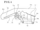
- FIG. 4is a cross-sectional view of a modified example of the seat cushion adjusting apparatus according to the embodiment disclosed here.
- a seat cushion adjusting apparatuswill be explained with reference to illustrations of drawings as follows.
- Directionssuch as longitudinal (front and rear sides), width (right and left sides) described hereinafter, or similar expressions correspond to an orientation of a seat 1 for a vehicle such as an automobile unless otherwise specified.
- FIG. 1shows a schematic view of the seat 1 arranged at a driver's seat side of the vehicle.
- the seat 1 for the vehicleincludes a seat cushion 2 configuring a seating surface, a seat back 3 tiltably supported at a rear end of the seat cushion 2 , and a headrest 4 supported at an upper end of the seat back 3 in a vertical direction of the vehicle.
- FIG. 2is a perspective view illustrating a configuration of a front portion of the seat cushion 2 .
- a base member 11 serving as a support memberis arranged at the front portion of the seat cushion 2 .
- the base member 11is formed by a metallic plate while extending in the width direction of the seat cushion 2 .
- the base member 11includes a pair of side plate portions 11 a arranged at side ends of the seat cushion 2 in the width direction and a ceiling plate portion 11 b connecting the pair of side plate portions 11 a at respective upper ends thereof.
- the base member 11is formed into an approximately portal shape in cross section and is fixed to a seat cushion frame to configure a frame of the seat cushion 2 together with the seat cushion frame.
- a first end of a lever 12 formed by a metallic bar memberis rotatably connected to each of the side plate portions 11 a of the base member 11 around a first rotary shaft 71 extending in the width direction at each of the side ends of the seat cushion 2 .
- a first end 13 A of a first gear plate 13is rotatably connected to a second end of the lever 12 around a second rotary shaft 72 extending in the width direction of the seat cushion 2 .
- the first gear plate 13is formed by a metallic plate-shaped elongated member.
- a third rotary shaft 73 extending in the width direction at each of the side ends of the seat cushion 2is rotatably connected to a second end 13 B of the first gear plate 13 .
- the first gear plate 13includes a first gear 13 a tracing a circular arc trajectory of a rotation about the third rotary shaft 73 (rotational axis of the first gear 13 ).
- a second gear plate 14is arranged at a front side of the first gear plate 13 in the longitudinal direction so as to rotate around a fourth rotary shaft 74 extending in the width direction at each of the side ends of the seat cushion 2 .
- the second gear plate 14is formed by a plate member meshing with the first gear 13 a .
- the second gear plate 14includes a second gear 14 a tracing a circular arc trajectory of a rotation about the fourth rotary shaft 74 (rotational axis of the second gear 14 ).
- a shaft member 15 configuring the fourth rotary shaft 74 and a drum 31 that serves as an adjustment member described beloware fixed to the second gear plate 14 .
- a fixing member 37 fixed to each of side plate portions 34 of the drum 31is inserted in a groove 14 b of the second gear 14 , which is positioned in the opposite direction from the second gear 14 a of the second gear plate 14 in the longitudinal direction. Accordingly, when the second gear plate 14 rotates around the fourth rotary shaft 74 , the drum 31 also rotates around the fourth rotary shaft 74 .
- the shaft member 15may be directly fixed to the side plate portion 34 of the drum 31 without the use of the fixing member 37 and the groove 14 b.
- the third and fourth rotary shafts 73 and 74are arranged at a transmission member 17 including a main body portion 17 a and connecting plate portions 17 b .
- the main body portion 17 a of the transmission member 17is formed in a bar or a tube extending in the width direction of the seat 1 .
- Each of the connecting plate portions 17 bis connected to the main body portion 17 a in perpendicular thereto.
- the third rotary shaft 73is arranged at one of both ends of the connecting plate 17 b and the fourth rotary shaft 74 is arranged on a rotational axis of the main body portion 17 a .
- the main body portion 17 amay be fixed to an intermediate portion of the connecting plate 17 b and the third and fourth rotary shafts 73 and 74 may be arranged respectively at the both ends of the connecting plate 17 b.
- a tongue-shaped attaching member 18 extending toward the rear side of the seat 1is fixed to an intermediate portion of a longitudinal direction of the transmission member 17 .
- a fixing member 19configured by a metallic plate and formed into an approximately portal shape in cross section is fixed to a lower surface of the base member 11 in the width direction (at the intermediate portion of the longitudinal direction of the transmission member 17 ).
- a driving member 20is supported at a lower end of the fixing member 19 .
- the driving member 20includes an electric motor 21 , a speed reduction mechanism 22 , and a feed screw 23 .
- the electric motor 21is a source of power.
- the speed reduction mechanism 22is attached to the fixing member 19 while holding the electric motor 21 .
- the feed screw 23 extending in the longitudinal direction of the seat 1meshes with a nut member arranged within the speed reduction mechanism 22 . Further, a front end portion 23 a of the feed screw 23 is attached to the attaching member 18 .
- the driving member 20is configured so that rotations of the electric motor 21 are reduced by the speed reduction mechanism 22 to thereby rotate an internal thread of the nut member arranged within the speed reduction mechanism 22 . Accordingly, the feed screw 23 comes in and out from the speed reduction mechanism 22 in the longitudinal direction. An axial rotation of the feed screw 23 is restricted by the attaching member 18 .
- the transmission member 17 connected to the front end portion 23 a of the feed screw 23 via the attaching member 18moves in the longitudinal direction.
- the driving member 20 , the transmission member 17 , the lever 12 , the first gear plate 13 , and the second gear plate 14configure a movement mechanism 26 .
- the driving mechanism 20is basically arranged so as to be accommodated within an area located below the base member 11 in the longitudinal direction. That is, the driving mechanism 20 is provided so as to overlap with a portion of each of the lever 12 , the first gear plate 13 , and the second gear plate 14 in the longitudinal direction of the seat 1 .
- the movement of the feed screw 23 in the longitudinal directionis restricted in a predetermined range by an annular stopper 24 arranged behind the front end portion 23 a and by a rear end portion of the feed screw 23 in the longitudinal direction.
- the front end portion 23 a of the feed screw 23is movably connected to the attaching member 18 so as to allow the movement of the transmission member 17 .
- the transmission member 17is formed into the single bar or the single tube extending in the overall width direction; however, it is not limited to such configuration.
- the single electric motor 21 , the single speed reduction mechanism 22 , and the single feed screw 23may be arranged at each of the right and left sides of the seat 1 .
- the transmission mechanism 17may be divided into two portions and each portion of the transmission mechanism 17 may be connected to each feed screw 23 .
- the electric motor 21 , the speed reduction mechanism 22 , and the feed screw 23may be arranged at only one of the right and left sides of the seat 1 while a driven mechanism is arranged at the other of the right and left sides of the seat 1 so as to be driven in accordance with the movement of the feed screw 23 at one of the above-mentioned right and left sides.
- the drum 31 serving as the adjustment member extending in the width direction and formed by a metallic plateis arranged at a front side of the base member 11 .
- the drum 31is integrally formed by a drum surface portion 32 , a flat surface portion 33 , a pair of side plate portions 34 and is shaped like a canopy top.
- the drum surface portion 32has a circular arc shaped cross section.
- the flat surface portion 33has a cross section continuously formed with a lower end of the drum surface portion 32 and linearly extending in a direction that is tangent to the cross section of the circular arc of the drum surface portion 32 .
- the side plate portions 34respectively extend downwardly at right and left side ends of the drum surface portion 32 and in parallel with the side plate portions 11 a of the base member 11 in the width direction. Further, the fixing member 37 having an axial line extending in the width direction is fixed to each of the side plate portions 34 and an end portion of the fixing member 37 is inserted in the groove 14 b of the second gear plate 14 (see FIG. 3A and FIG. 3B ).
- a seating member 41 configuring an outer shape of the seat cushion 2is supported at the base member 11 .
- the seating member 41includes a front surface 42 and a cushion member 43 .
- the front surface 42is exposed to an outer side of the seat cushion 2 for an occupant seated at the seat 1 .
- the front surface 42is formed by a leather or a cloth configuring the outer shape of the seat cushion 2 .
- the cushion member 43is arranged in a lower side of the front surface 42 and formed by a buffer material (such as a urethane pad).
- the seating member 41includes a seating portion 41 c and a front end portion 41 a .
- the seating portion 41 csupports buttocks of the seated occupant.
- the front end portion 41 aextends downwardly from a front edge of the seating portion 41 c while being wrapped on the drum surface portion 32 of the drum 31 so as to extend along the flat surface 33 of the drum 31 .
- An edge of the front surface 42 covering the cushion member 43is fixedly attached to an edge of the flat surface portion 33 by means of an adhesive or is appropriately attached to the edge of the flat surface portion 33 by means of a fastening member to thereby fasten the front end portion 41 a of the seating member 41 to the drum 31 . Accordingly, the front end portion 41 a is moved in accordance with a movement or rotation of the drum 31 to adjust an outer shape of the seating member 41 .
- a portion at the front end portion 41 a in the seating portion 41 c(a portion provided between Point P 1 and Point P 2 shown in FIG. 3A and FIG. 3B ) is a deformable portion 41 d .
- a shape of the deformable portion 41 dis deformable by the rotation of the drum 31 .
- FIGS. 3A and 3BAn adjusting operation of the seat cushion adjusting apparatus according to the embodiment will be explained mainly with reference to FIGS. 3A and 3B as follows.
- the front end portion 41 a of the seating member 41is rotated in accordance with the rotation of the flat surface portion 33 of the drum 31 so as to be retracted toward the rear side of the seat 1 , therefore curving the deformable portion 41 d along the drum surface portion 32 of the drum 31 . Accordingly, the front end portion 41 a is contracted in the longitudinal direction (this corresponds to a contracted state) so that a femoral region of the seated occupant, which is short in length, is appropriately supported by the seating member 41 .
- the transmission member 17 , the lever 12 , the first gear plate 13 , and the second gear plate 14are accommodated in a space (space located at a lower side of the seating member 41 ) surrounded by the base member 11 and the drum 31 at a lower side of the base member 11 and a rear side of the drum 31 in the longitudinal direction of the seat 1 .
- a slider 10 including a bearing 10 b and a rod 10 a that slidably moves relative to the bearing 10 b in the longitudinal direction of the seat 1is fixed to the transmission member 17 to thereby allow the transmission member 17 to move relative to the base member 11 in the longitudinal direction.
- the transmission member 17 , the first gear plate 13 , and the second gear plate 14are smoothly moved relative to the base member 11 in the longitudinal direction.
- the first gear plate 13 and the second gear plate 14 rotatably supported by the transmission member 17 and the second rotary shaft 72 of the lever 12are moved simultaneously in accordance with the movement of the transmission member 17 toward the front side of the seat 1 .
- the second end of the lever 12is rotated around the first rotary shaft 71 so as to trace only a circular arc trajectory of the rotation and the first gear plate 13 is forcibly rotated by the lever 12 around the third rotary shaft 73 .
- the second gear plate 14rotates around the fourth rotary shaft 74 relative to the transmission member 17 in accordance with the rotation of the first gear plate 13 .
- the drum 31is rotated in a clockwise direction shown in FIG. 3B around the fourth rotary shaft 74 in accordance with the rotation of the second gear plate 14 so as to protrude toward the front side of the seat 1 .
- the front end portion 41 a of the seating member 41is also moved along with the rotation of the drum surface portion 32 so as to protrude toward the front side.
- the deformable portion 41 dis deformed in a direction where a curvature of the deformable portion 41 d decreases and the deformable portion 41 d is deployed in the longitudinal direction (this corresponds to a deployed state) so that the femoral region of the seated occupant, which is long in length, is desirably supported by the seating member 41 . That is, the front end portion 41 a wrapped on the drum 31 (drum surface portion 31 ) is deployed to vary the longitudinal length of the seat 1 , that is the longitudinal length of the seating member 41 , along with the rotation of the drum 31 . Thus, the femoral region of the occupant is desirably supported depending on his/her physical attribute.
- Slits 43 aare formed in the cushion member 43 (see FIG. 3B ) to thereby prevent the deformable portion 41 d and the seating member 41 from being strained excessively when the front end portion 41 a of the seating member 41 is contracted and deployed.
- a predetermined surface 41 bis imaginarily provided between the front surface 42 of the seating member 41 and a back surface of the seating member 41 .
- the front end portion 41 a of the seating member 41is set so as not to change at the predetermined surface 41 b , and the length thereof is maintained to be substantially the same. In other words, even when the drum 31 is rotated or the like, the predetermined surface 41 b is neither strained nor compressed.
- rear and front end positions of the predetermined surface 41 b at the deformable portion 41 dare respectively determined as first and second points P 1 and P 2 (the right side in FIG. 3A and FIG. 3B corresponds to the rear side of the seat 1 ).
- a length of the predetermined surface 41 b between the first and second points P 1 and P 2 shown in FIG. 3Ais defined as a first length LA 1 and a length of the predetermined surface 41 b between the first and second points P 1 and P 2 shown in FIG. 3B is defined as a second length LB 1 .
- a relationship between the first and second lengths LA 1 and LB 1is determined as follows: “LA 1 ⁇ LB 1 (LA 1 is nearly equal to LB 1 )”.
- the predetermined surface 41 bis positioned closer to a front surface of the deformable portion 41 d than an intermediate surface of the deformable portion 41 d , which is provided between the front surface of the deformable portion 41 d and a back surface the deformable portion 41 d.
- the seat cushion adjusting apparatusmay function as an ottoman that supports the lower legs of the occupant seated at an passenger seat or a rear seat.
- the lever 12rotates around a connecting portion (first rotary shaft 71 ) between the side plate portion 11 a and the lever 12 .
- the first gear plate 13rotates around a connecting portion (third rotary shaft 73 ) between the transmission member 17 and the first gear plate 13 .
- the first gear 13 a of the first gear plate 13meshes with the second gear 14 a of the second gear plate 14 . Accordingly, the second gear plate 14 is driven to rotate in accordance with the rotation of the first gear plate 13 .
- the second gear plate 14is rotatably connected to the drum 31 ; thereby, the drum 31 is moved in the longitudinal direction while being rotated by the movement mechanism 26 . That is, the movement of the lever 12 , the first gear plate 13 , and the second gear plate 14 is a smooth rotating movement around the first, third, and fourth rotary shafts 71 , 73 , and 74 , respectively, in which a loss of the power of the motor 21 is small (a frictional resistance is small). Additionally, a relative movement between the first gear 13 a and the second gear 14 a is a meshing movement in which a loss of the power of the motor 21 is small (a frictional resistance is small). Thus, an operating force for rotating the drum 31 is reduced and the motor 21 and the like serving as a source of power may be minimized.
- the movement mechanism 26includes the slider 10 slidably moving relative to the support member 11 in the longitudinal direction of the seat 1 .
- the slider 10 connected to the transmission member 17 , the first gear plate 13 , the second gear plate 14 , and the drum 31smoothly slides relative to the base member 11 in the longitudinal direction. Accordingly, a slide resistance between the base member 11 and the movement mechanism 26 is reduced. Consequently, the operating force for rotating the drum 31 is reduced and the motor 21 and the like serving as a source of power may be minimized.
- the support member 11includes the base member 11 directly supporting the seating member 41 . Further, when the drum 31 , 51 is moved in the longitudinal direction, the transmission member 17 , the lever 12 , the first gear 13 , and the second gear 14 are arranged in the space surrounded by the base member 11 and the drum 31 , 51 at the lower side of the base member 11 and at the rear side of the drum 31 , 51 in the longitudinal direction of the seat 1 .
- the transmission member 17 , the lever 12 , the first gear plate 13 , and the second gear plate 14are accommodated in the space surrounded by the base member 11 and the drum 31 at the lower side of the base member 11 and at the rear side of the drum 31 in the longitudinal direction. Accordingly, the transmission member 17 , the lever 12 , the first gear plate 13 , and the second gear plate 14 may keep a predetermined distance relative to the seating member 41 , therefore preventing the seating member 41 from interfering with the transmission member 17 , the lever 12 , the first gear plate 13 , and the second gear plate 14 and from being deformed. As a result, the occupant does not feel uncomfortable when being seated at the seat 1 .
- the seating member 41includes the seating portion 41 c , the front end portion 41 a , and the deformable portion 41 d integrally arranged with the seating portion 41 c and the front end portion 41 a and positioned between the seating portion 41 c and the front end portion 41 a .
- the deformable portion 41 dis deformable in accordance with the rotation of the drum 31 , 51 to move the first end portion 41 a in order to adjust the outer shape of the seat cushion 2 .
- the drum 31 , 51fastens thereto the front end portion 41 a so that a length between ends of the deformable portion 41 d in the vicinity of the seating portion 41 c and the front end portion 41 a , respectively, on the front surface of the deformable portion 41 d or a length between ends of the predetermined surface 41 b in the vicinity of the seating portion 41 c and the front end portion 41 a , respectively, is unchanged regardless of a rotating state of the drum 31 , 51 .
- the predetermined surface 41 bis provided between the front surface of the deformable portion 41 d and the back surface of the deformable portion 41 d.
- the front end portion 41 ais fastened to the drum 31 so that the length between the ends of the deformable portion 41 d in the vicinity of the seating portion 41 c and the front end portion 41 a , respectively, on the front surface of the deformable portion 41 d is unchanged; therefore, a variation of the length (expansion and contraction) of the front surface of the deformable portion 41 d is restricted.
- the predetermined surface 41 bis defined between the front and back surfaces of the deformable portion 41 d .
- the front end portion 41 ais fastened to the drum 31 so that the length between ends of the predetermined surface 41 b in the vicinity of the seating portion 41 c and the front end portion 41 a , respectively, is unchanged; therefore, the length of the deformable portion 41 d is prevented from unevenly changing in only one of the front and back surfaces of the deformable portion 41 d and the front and back surfaces of the deformable portion 41 d are inhibited from being excessively expanded or shrunk.
- specifications for gear teeth of the first and second gears 13 a and 14 a , arm lengths of the first and second gears 13 and 14 , a length of the lever 12are modified as required to thereby easily modify a rate of change of a rotation angle of the drum 31 , 51 relative to a stroke of the feed screw 23 .
- a design freedom of the seat cushion adjusting apparatusmay be increased.
Landscapes
- Engineering & Computer Science (AREA)
- Aviation & Aerospace Engineering (AREA)
- Transportation (AREA)
- Mechanical Engineering (AREA)
- Seats For Vehicles (AREA)
- Chair Legs, Seat Parts, And Backrests (AREA)
Abstract
Description
Claims (9)
Applications Claiming Priority (2)
| Application Number | Priority Date | Filing Date | Title |
|---|---|---|---|
| JP2009-163365 | 2009-07-10 | ||
| JP2009163365AJP5387185B2 (en) | 2009-07-10 | 2009-07-10 | Seat cushion adjustment device |
Publications (2)
| Publication Number | Publication Date |
|---|---|
| US20110006573A1 US20110006573A1 (en) | 2011-01-13 |
| US8167370B2true US8167370B2 (en) | 2012-05-01 |
Family
ID=43242897
Family Applications (1)
| Application Number | Title | Priority Date | Filing Date |
|---|---|---|---|
| US12/831,334Expired - Fee RelatedUS8167370B2 (en) | 2009-07-10 | 2010-07-07 | Seat cushion adjusting apparatus |
Country Status (4)
| Country | Link |
|---|---|
| US (1) | US8167370B2 (en) |
| EP (1) | EP2281713B1 (en) |
| JP (1) | JP5387185B2 (en) |
| CN (1) | CN101947027B (en) |
Cited By (83)
| Publication number | Priority date | Publication date | Assignee | Title |
|---|---|---|---|---|
| US20130285433A1 (en)* | 2012-04-25 | 2013-10-31 | Aisin Seiki Kabushiki Kaisha | Ottoman device |
| US8727374B1 (en) | 2013-01-24 | 2014-05-20 | Ford Global Technologies, Llc | Vehicle seatback with side airbag deployment |
| US20140203606A1 (en)* | 2013-01-24 | 2014-07-24 | Ford Global Technologies, Llc | Thin seat flex rest composite cushion extension |
| US20140239675A1 (en)* | 2011-08-08 | 2014-08-28 | Kintec-Solution Gmbh | Furniture piece |
| US8905431B1 (en) | 2013-09-24 | 2014-12-09 | Ford Global Technologies, Llc | Side airbag assembly for a vehicle seat |
| US9016784B2 (en) | 2013-01-24 | 2015-04-28 | Ford Global Technologies, Llc | Thin seat leg support system and suspension |
| US9061616B2 (en) | 2013-01-24 | 2015-06-23 | Ford Global Technologies, Llc | Articulating headrest assembly |
| US9096157B2 (en) | 2013-01-24 | 2015-08-04 | Ford Global Technologies, Llc | Seating assembly with air distribution system |
| US9126504B2 (en) | 2013-01-24 | 2015-09-08 | Ford Global Technologies, Llc | Integrated thin flex composite headrest assembly |
| US9126508B2 (en) | 2013-01-24 | 2015-09-08 | Ford Global Technologies, Llc | Upper seatback pivot system |
| US20150258914A1 (en)* | 2014-03-13 | 2015-09-17 | Hyundai Motor Company | Seat cushion extension apparatus |
| US9187019B2 (en) | 2013-10-17 | 2015-11-17 | Ford Global Technologies, Llc | Thigh support for customer accommodation seat |
| US9193284B2 (en) | 2013-06-11 | 2015-11-24 | Ford Global Technologies, Llc | Articulating cushion bolster for ingress/egress |
| US9216677B2 (en) | 2013-01-24 | 2015-12-22 | Ford Global Technologies, Llc | Quick-connect trim carrier attachment |
| US9302643B2 (en) | 2014-04-02 | 2016-04-05 | Ford Global Technologies, Llc | Vehicle seating assembly with side airbag deployment |
| US9315130B2 (en) | 2013-11-11 | 2016-04-19 | Ford Global Technologies, Llc | Articulating head restraint |
| US9333882B2 (en) | 2014-10-03 | 2016-05-10 | Ford Global Technologies, Llc | Manual upper seatback support |
| US9340131B1 (en) | 2014-11-06 | 2016-05-17 | Ford Global Technologies, Llc | Head restraint with a multi-cell bladder assembly |
| US20160144744A1 (en)* | 2014-11-25 | 2016-05-26 | Hyundai Motor Company | Seat cushion extension apparatus |
| US9365143B2 (en) | 2013-12-12 | 2016-06-14 | Ford Global Technologies, Llc | Rear seat modular cushion |
| US9365142B1 (en) | 2015-01-20 | 2016-06-14 | Ford Global Technologies, Llc | Manual independent thigh extensions |
| US9399418B2 (en) | 2013-01-24 | 2016-07-26 | Ford Global Technologies, Llc | Independent cushion extension and thigh support |
| US9409504B2 (en) | 2013-01-24 | 2016-08-09 | Ford Global Technologies, Llc | Flexible seatback system |
| US9415713B2 (en) | 2013-01-24 | 2016-08-16 | Ford Global Technologies, Llc | Flexible seatback system |
| US9421894B2 (en) | 2014-04-02 | 2016-08-23 | Ford Global Technologies, Llc | Vehicle seating assembly with manual independent thigh supports |
| US9505322B2 (en) | 2013-10-25 | 2016-11-29 | Ford Global Technologies, Llc | Manual lumbar pump assembly |
| US9517777B2 (en) | 2014-11-06 | 2016-12-13 | Ford Global Technologies, Llc | Lane departure feedback system |
| US9527419B2 (en) | 2014-03-31 | 2016-12-27 | Ford Global Technologies, Llc | Vehicle seating assembly with manual cushion tilt |
| US9527418B2 (en) | 2013-09-12 | 2016-12-27 | Ford Global Technologies, Llc | Semi rigid push/pull vented envelope system |
| US9566884B2 (en) | 2013-11-11 | 2017-02-14 | Ford Global Technologies, Llc | Powered head restraint electrical connector |
| US9566930B2 (en) | 2015-03-02 | 2017-02-14 | Ford Global Technologies, Llc | Vehicle seat assembly with side-impact airbag deployment mechanism |
| US9573528B1 (en) | 2015-08-25 | 2017-02-21 | Ford Global Technologies, Llc | Integrated seatback storage |
| US9593642B2 (en) | 2014-12-19 | 2017-03-14 | Ford Global Technologies, Llc | Composite cam carrier |
| EP3141419A1 (en) | 2015-09-09 | 2017-03-15 | Volvo Car Corporation | A vehicle seat |
| US9616776B1 (en) | 2015-11-16 | 2017-04-11 | Ford Global Technologies, Llc | Integrated power thigh extender |
| US9649963B2 (en) | 2014-03-04 | 2017-05-16 | Ford Global Technologies, Pllc | Trim and foam assembly for a vehicle seat |
| US9663000B2 (en) | 2015-01-16 | 2017-05-30 | Ford Global Technologies, Llc | Vehicle seat configured to improve access |
| US9688174B2 (en) | 2015-08-07 | 2017-06-27 | Ford Global Technologies, Llc | Multi-cell seat cushion assembly |
| US9694741B2 (en) | 2014-08-25 | 2017-07-04 | Ford Global Technologies, Llc | Ambient functional lighting of a seat |
| US9707877B2 (en) | 2015-01-20 | 2017-07-18 | Ford Global Technologies, Llc | Independent thigh extension and support trim carrier |
| US9718387B2 (en) | 2015-08-03 | 2017-08-01 | Ford Global Technologies, Llc | Seat cushion module for a vehicle seating assembly |
| US9756408B2 (en) | 2016-01-25 | 2017-09-05 | Ford Global Technologies, Llc | Integrated sound system |
| US9771003B2 (en) | 2014-10-29 | 2017-09-26 | Ford Global Technologies, Llc | Apparatus for customizing a vehicle seat for an occupant |
| US9776533B2 (en) | 2014-10-03 | 2017-10-03 | Ford Global Technologies, Llc | Torsion bar upper seatback support assembly |
| US9776543B2 (en) | 2016-01-25 | 2017-10-03 | Ford Global Technologies, Llc | Integrated independent thigh supports |
| US9789790B2 (en) | 2014-10-03 | 2017-10-17 | Ford Global Technologies, Llc | Tuned flexible support member and flexible suspension features for comfort carriers |
| US9802535B2 (en) | 2015-04-27 | 2017-10-31 | Ford Global Technologies, Llc | Seat having ambient lighting |
| US9802512B1 (en) | 2016-04-12 | 2017-10-31 | Ford Global Technologies, Llc | Torsion spring bushing |
| US9809131B2 (en) | 2015-12-04 | 2017-11-07 | Ford Global Technologies, Llc | Anthropomorphic pivotable upper seatback support |
| US9834166B1 (en) | 2016-06-07 | 2017-12-05 | Ford Global Technologies, Llc | Side airbag energy management system |
| US9845029B1 (en) | 2016-06-06 | 2017-12-19 | Ford Global Technologies, Llc | Passive conformal seat with hybrid air/liquid cells |
| US9849856B1 (en) | 2016-06-07 | 2017-12-26 | Ford Global Technologies, Llc | Side airbag energy management system |
| US9849817B2 (en) | 2016-03-16 | 2017-12-26 | Ford Global Technologies, Llc | Composite seat structure |
| US9889773B2 (en) | 2016-04-04 | 2018-02-13 | Ford Global Technologies, Llc | Anthropomorphic upper seatback |
| US9902293B2 (en) | 2013-01-24 | 2018-02-27 | Ford Global Technologies, Llc | Independent cushion extension with optimized leg-splay angle |
| US9914421B2 (en) | 2016-01-15 | 2018-03-13 | Ford Global Technologies, Llc | Seatback flexible slip plane joint for side air bag deployment |
| US9914378B1 (en) | 2016-12-16 | 2018-03-13 | Ford Global Technologies, Llc | Decorative and functional upper seatback closeout assembly |
| US9931999B2 (en) | 2015-12-17 | 2018-04-03 | Ford Global Technologies, Llc | Back panel lower clip anchorage features for dynamic events |
| US9994135B2 (en) | 2016-03-30 | 2018-06-12 | Ford Global Technologies, Llc | Independent cushion thigh support |
| US10035442B2 (en) | 2016-01-25 | 2018-07-31 | Ford Global Technologies, Llc | Adjustable upper seatback module |
| US10046681B2 (en) | 2016-04-12 | 2018-08-14 | Ford Global Technologies, Llc | Articulating mechanical thigh extension composite trim payout linkage system |
| US10046683B2 (en) | 2014-01-23 | 2018-08-14 | Ford Global Technologies, Llc | Suspension seat back and cushion system having an inner suspension panel |
| US10046682B2 (en) | 2015-08-03 | 2018-08-14 | Ford Global Technologies, Llc | Back cushion module for a vehicle seating assembly |
| US10052990B2 (en) | 2016-01-25 | 2018-08-21 | Ford Global Technologies, Llc | Extended seatback module head restraint attachment |
| US10065570B2 (en) | 2014-12-10 | 2018-09-04 | Ford Global Technologies, Llc | Electronic device holder for a vehicle seat |
| US10081279B2 (en) | 2016-04-12 | 2018-09-25 | Ford Global Technologies, Llc | Articulating thigh extension trim tensioning slider mechanism |
| US10093214B2 (en) | 2016-01-14 | 2018-10-09 | Ford Global Technologies, Llc | Mechanical manual leg tilt |
| US10166895B2 (en) | 2016-06-09 | 2019-01-01 | Ford Global Technologies, Llc | Seatback comfort carrier |
| US10202052B2 (en) | 2016-05-20 | 2019-02-12 | Toyota Boshoku Kabushiki Kaisha | Seat cushion adjuster, seat, and adjustment method of seat |
| US10220737B2 (en) | 2016-04-01 | 2019-03-05 | Ford Global Technologies, Llc | Kinematic back panel |
| US10239431B2 (en) | 2016-09-02 | 2019-03-26 | Ford Global Technologies, Llc | Cross-tube attachment hook features for modular assembly and support |
| US10279714B2 (en) | 2016-08-26 | 2019-05-07 | Ford Global Technologies, Llc | Seating assembly with climate control features |
| US10286824B2 (en) | 2016-08-24 | 2019-05-14 | Ford Global Technologies, Llc | Spreader plate load distribution |
| US10286818B2 (en) | 2016-03-16 | 2019-05-14 | Ford Global Technologies, Llc | Dual suspension seating assembly |
| US10329020B2 (en)* | 2014-04-03 | 2019-06-25 | Safran Seats Usa Llc | Integrated deployable leg rest for reclining passenger seats |
| US10377273B2 (en)* | 2016-10-04 | 2019-08-13 | Tachi-S Co., Ltd. | Vehicle seat |
| US10377279B2 (en) | 2016-06-09 | 2019-08-13 | Ford Global Technologies, Llc | Integrated decking arm support feature |
| US10391910B2 (en) | 2016-09-02 | 2019-08-27 | Ford Global Technologies, Llc | Modular assembly cross-tube attachment tab designs and functions |
| US10399465B2 (en) | 2016-05-20 | 2019-09-03 | Toyota Boshoku Kabushiki Kaisha | Seat cushion adjuster, seat, and adjustment method of seat |
| US10471874B2 (en) | 2014-09-02 | 2019-11-12 | Ford Global Technologies, Llc | Massage bladder matrix |
| US10596936B2 (en) | 2017-05-04 | 2020-03-24 | Ford Global Technologies, Llc | Self-retaining elastic strap for vent blower attachment to a back carrier |
| US10625646B2 (en) | 2016-04-12 | 2020-04-21 | Ford Global Technologies, Llc | Articulating mechanical thigh extension composite trim payout linkage system |
| US12162392B2 (en)* | 2022-01-21 | 2024-12-10 | Magna Seating Research & Development (Chongqing) Co., Ltd. | Seamless leg rest device for automobile seats |
Families Citing this family (18)
| Publication number | Priority date | Publication date | Assignee | Title |
|---|---|---|---|---|
| JP5954962B2 (en)* | 2011-11-16 | 2016-07-20 | 株式会社イトーキ | Chair |
| US9241572B1 (en)* | 2014-08-19 | 2016-01-26 | Yao-Chuan Wu | Cushion structure |
| CN104309499B (en)* | 2014-09-29 | 2016-09-14 | 上海胜华波汽车电器有限公司 | A kind of vehicle seat recliner mechanism and seat |
| JP2016215823A (en) | 2015-05-20 | 2016-12-22 | アイシン精機株式会社 | Seat cushion adjustment device |
| JP6561664B2 (en) | 2015-08-03 | 2019-08-21 | テイ・エス テック株式会社 | Vehicle seat |
| JP2018095113A (en)* | 2016-12-14 | 2018-06-21 | トヨタ紡織株式会社 | Drive device |
| JP2018100046A (en)* | 2016-12-21 | 2018-06-28 | トヨタ紡織株式会社 | Driving device |
| US11077782B2 (en) | 2016-12-27 | 2021-08-03 | Adient Engineering and IP GmbH | Vehicle seat with extendable and retractable ottoman |
| CN108263249A (en)* | 2016-12-30 | 2018-07-10 | 福州明芳汽车部件工业有限公司 | Automotive seat extends support component |
| DE102017204894A1 (en)* | 2017-03-23 | 2018-09-27 | Airbus Operations Gmbh | Passenger seat with an expandable seat element and passenger cabin area |
| JP6794905B2 (en)* | 2017-04-06 | 2020-12-02 | トヨタ紡織株式会社 | Vehicle seat |
| GB2563389B (en)* | 2017-06-09 | 2020-06-17 | Ford Global Tech Llc | Expandable seat for a vehicle |
| US20190119001A1 (en)* | 2017-10-20 | 2019-04-25 | Jacob Berger | Post dental or medical procedure personal care kit |
| JP2019136184A (en) | 2018-02-07 | 2019-08-22 | トヨタ紡織株式会社 | Cushion length variable apparatus |
| DE102019214681A1 (en)* | 2019-09-25 | 2021-03-25 | Psa Automobiles Sa | Seat for a motor vehicle with two leg rests that span an angle A between them |
| NO347748B1 (en)* | 2020-04-01 | 2024-03-11 | Sykkylven Staal As | Seating furniture with movable footrest |
| JP7713866B2 (en)* | 2021-11-19 | 2025-07-28 | 日本発條株式会社 | Vehicle seat |
| DE102023002486A1 (en) | 2023-06-20 | 2024-12-24 | Mercedes-Benz Group AG | Seat cushion depth adjustment in conjunction with a calf support |
Citations (9)
| Publication number | Priority date | Publication date | Assignee | Title |
|---|---|---|---|---|
| US4693513A (en)* | 1987-01-27 | 1987-09-15 | General Motors Corporation | Thigh support for vehicle seat |
| JPH0728454U (en) | 1993-11-09 | 1995-05-30 | 株式会社東洋シート | Vehicle seat device |
| US6435610B2 (en)* | 1999-11-30 | 2002-08-20 | Aisin Seiki Kabushiki Kaisha | Vertical movement apparatus for vehicle seat |
| JP2004155341A (en) | 2002-11-07 | 2004-06-03 | Toyota Motor Corp | Vehicle seat |
| US6921133B2 (en)* | 2001-02-21 | 2005-07-26 | Daihatsu Motor Co., Ltd. | Seat for car |
| US20060091711A1 (en) | 2004-11-04 | 2006-05-04 | Aisin Seiki Kabushiki Kaisha | Vehicle seat apparatus |
| JP2007118706A (en) | 2005-10-26 | 2007-05-17 | Aisin Seiki Co Ltd | Seat seating surface length adjustment device |
| US7229134B2 (en) | 2003-07-16 | 2007-06-12 | Aisin Seiki Kabushiki Kasiha | Seat apparatus for vehicle |
| EP2085262A1 (en) | 2008-01-31 | 2009-08-05 | Aisin Seiki Kabushiki Kaisha | Seat cushion adjusting apparatus |
Family Cites Families (4)
| Publication number | Priority date | Publication date | Assignee | Title |
|---|---|---|---|---|
| JPH0714944U (en)* | 1993-08-20 | 1995-03-14 | デルタ工業株式会社 | Seat cushion length adjustment device |
| JP4438564B2 (en)* | 2004-03-26 | 2010-03-24 | トヨタ紡織株式会社 | Vehicle seat with variable seat cushion length |
| JP2008087554A (en)* | 2006-09-29 | 2008-04-17 | Aisin Seiki Co Ltd | Vehicle seat device |
| JP5181217B2 (en)* | 2007-10-01 | 2013-04-10 | コクヨ株式会社 | Chair |
- 2009
- 2009-07-10JPJP2009163365Apatent/JP5387185B2/ennot_activeExpired - Fee Related
- 2010
- 2010-07-07USUS12/831,334patent/US8167370B2/ennot_activeExpired - Fee Related
- 2010-07-07EPEP10168661.6Apatent/EP2281713B1/ennot_activeNot-in-force
- 2010-07-08CNCN2010102282108Apatent/CN101947027B/ennot_activeExpired - Fee Related
Patent Citations (11)
| Publication number | Priority date | Publication date | Assignee | Title |
|---|---|---|---|---|
| US4693513A (en)* | 1987-01-27 | 1987-09-15 | General Motors Corporation | Thigh support for vehicle seat |
| JPH0728454U (en) | 1993-11-09 | 1995-05-30 | 株式会社東洋シート | Vehicle seat device |
| US6435610B2 (en)* | 1999-11-30 | 2002-08-20 | Aisin Seiki Kabushiki Kaisha | Vertical movement apparatus for vehicle seat |
| US6921133B2 (en)* | 2001-02-21 | 2005-07-26 | Daihatsu Motor Co., Ltd. | Seat for car |
| JP2004155341A (en) | 2002-11-07 | 2004-06-03 | Toyota Motor Corp | Vehicle seat |
| US7229134B2 (en) | 2003-07-16 | 2007-06-12 | Aisin Seiki Kabushiki Kasiha | Seat apparatus for vehicle |
| US20060091711A1 (en) | 2004-11-04 | 2006-05-04 | Aisin Seiki Kabushiki Kaisha | Vehicle seat apparatus |
| JP2007118706A (en) | 2005-10-26 | 2007-05-17 | Aisin Seiki Co Ltd | Seat seating surface length adjustment device |
| US7614693B2 (en) | 2005-10-26 | 2009-11-10 | Aisin Seiki Kabushiki Kaisha | Seating area adjuster |
| EP2085262A1 (en) | 2008-01-31 | 2009-08-05 | Aisin Seiki Kabushiki Kaisha | Seat cushion adjusting apparatus |
| US20090195041A1 (en) | 2008-01-31 | 2009-08-06 | Aisin Seiki Kabushiki Kaisha | Seat cushion adjusting apparatus |
Non-Patent Citations (1)
| Title |
|---|
| European Search Report dated Dec. 21, 2010, issued by the European Patent Office in corresponding European Patent Application No. 10 16 8661. |
Cited By (97)
| Publication number | Priority date | Publication date | Assignee | Title |
|---|---|---|---|---|
| US20140239675A1 (en)* | 2011-08-08 | 2014-08-28 | Kintec-Solution Gmbh | Furniture piece |
| US20130285433A1 (en)* | 2012-04-25 | 2013-10-31 | Aisin Seiki Kabushiki Kaisha | Ottoman device |
| US9198516B2 (en)* | 2012-04-25 | 2015-12-01 | Aisin Seiki Kabushiki Kaisha | Ottoman device |
| US9061616B2 (en) | 2013-01-24 | 2015-06-23 | Ford Global Technologies, Llc | Articulating headrest assembly |
| US9707873B2 (en) | 2013-01-24 | 2017-07-18 | Ford Global Technologies, Llc | Flexible seatback system |
| US9016784B2 (en) | 2013-01-24 | 2015-04-28 | Ford Global Technologies, Llc | Thin seat leg support system and suspension |
| US9016783B2 (en)* | 2013-01-24 | 2015-04-28 | Ford Global Technologies, Llc | Thin seat flex rest composite cushion extension |
| US9902293B2 (en) | 2013-01-24 | 2018-02-27 | Ford Global Technologies, Llc | Independent cushion extension with optimized leg-splay angle |
| US9096157B2 (en) | 2013-01-24 | 2015-08-04 | Ford Global Technologies, Llc | Seating assembly with air distribution system |
| US9126504B2 (en) | 2013-01-24 | 2015-09-08 | Ford Global Technologies, Llc | Integrated thin flex composite headrest assembly |
| US9126508B2 (en) | 2013-01-24 | 2015-09-08 | Ford Global Technologies, Llc | Upper seatback pivot system |
| US9707870B2 (en) | 2013-01-24 | 2017-07-18 | Ford Global Technologies, Llc | Flexible seatback system |
| US9415713B2 (en) | 2013-01-24 | 2016-08-16 | Ford Global Technologies, Llc | Flexible seatback system |
| US9409504B2 (en) | 2013-01-24 | 2016-08-09 | Ford Global Technologies, Llc | Flexible seatback system |
| US20140203606A1 (en)* | 2013-01-24 | 2014-07-24 | Ford Global Technologies, Llc | Thin seat flex rest composite cushion extension |
| US9216677B2 (en) | 2013-01-24 | 2015-12-22 | Ford Global Technologies, Llc | Quick-connect trim carrier attachment |
| US9399418B2 (en) | 2013-01-24 | 2016-07-26 | Ford Global Technologies, Llc | Independent cushion extension and thigh support |
| US9873362B2 (en) | 2013-01-24 | 2018-01-23 | Ford Global Technologies, Llc | Flexible seatback system |
| US8727374B1 (en) | 2013-01-24 | 2014-05-20 | Ford Global Technologies, Llc | Vehicle seatback with side airbag deployment |
| US9873360B2 (en) | 2013-01-24 | 2018-01-23 | Ford Global Technologies, Llc | Flexible seatback system |
| US9649962B2 (en) | 2013-01-24 | 2017-05-16 | Ford Global Technologies, Llc | Independent cushion extension and thigh support |
| US9193284B2 (en) | 2013-06-11 | 2015-11-24 | Ford Global Technologies, Llc | Articulating cushion bolster for ingress/egress |
| US9527418B2 (en) | 2013-09-12 | 2016-12-27 | Ford Global Technologies, Llc | Semi rigid push/pull vented envelope system |
| US8905431B1 (en) | 2013-09-24 | 2014-12-09 | Ford Global Technologies, Llc | Side airbag assembly for a vehicle seat |
| US9187019B2 (en) | 2013-10-17 | 2015-11-17 | Ford Global Technologies, Llc | Thigh support for customer accommodation seat |
| US9505322B2 (en) | 2013-10-25 | 2016-11-29 | Ford Global Technologies, Llc | Manual lumbar pump assembly |
| US9315130B2 (en) | 2013-11-11 | 2016-04-19 | Ford Global Technologies, Llc | Articulating head restraint |
| US9566884B2 (en) | 2013-11-11 | 2017-02-14 | Ford Global Technologies, Llc | Powered head restraint electrical connector |
| US9365143B2 (en) | 2013-12-12 | 2016-06-14 | Ford Global Technologies, Llc | Rear seat modular cushion |
| US10046683B2 (en) | 2014-01-23 | 2018-08-14 | Ford Global Technologies, Llc | Suspension seat back and cushion system having an inner suspension panel |
| US9649963B2 (en) | 2014-03-04 | 2017-05-16 | Ford Global Technologies, Pllc | Trim and foam assembly for a vehicle seat |
| US20150258914A1 (en)* | 2014-03-13 | 2015-09-17 | Hyundai Motor Company | Seat cushion extension apparatus |
| US9371011B2 (en)* | 2014-03-13 | 2016-06-21 | Hyundai Motor Company | Seat cushion extension apparatus |
| US9527419B2 (en) | 2014-03-31 | 2016-12-27 | Ford Global Technologies, Llc | Vehicle seating assembly with manual cushion tilt |
| US10065546B2 (en) | 2014-04-02 | 2018-09-04 | Ford Global Technologies, Llc | Vehicle seating assembly with manual independent thigh supports |
| US9421894B2 (en) | 2014-04-02 | 2016-08-23 | Ford Global Technologies, Llc | Vehicle seating assembly with manual independent thigh supports |
| US9302643B2 (en) | 2014-04-02 | 2016-04-05 | Ford Global Technologies, Llc | Vehicle seating assembly with side airbag deployment |
| US10329020B2 (en)* | 2014-04-03 | 2019-06-25 | Safran Seats Usa Llc | Integrated deployable leg rest for reclining passenger seats |
| US9694741B2 (en) | 2014-08-25 | 2017-07-04 | Ford Global Technologies, Llc | Ambient functional lighting of a seat |
| US10471874B2 (en) | 2014-09-02 | 2019-11-12 | Ford Global Technologies, Llc | Massage bladder matrix |
| US9789790B2 (en) | 2014-10-03 | 2017-10-17 | Ford Global Technologies, Llc | Tuned flexible support member and flexible suspension features for comfort carriers |
| US10369905B2 (en) | 2014-10-03 | 2019-08-06 | Ford Global Technologies, Llc | Tuned flexible support member and flexible suspension features for comfort carriers |
| US9776533B2 (en) | 2014-10-03 | 2017-10-03 | Ford Global Technologies, Llc | Torsion bar upper seatback support assembly |
| US9333882B2 (en) | 2014-10-03 | 2016-05-10 | Ford Global Technologies, Llc | Manual upper seatback support |
| US9771003B2 (en) | 2014-10-29 | 2017-09-26 | Ford Global Technologies, Llc | Apparatus for customizing a vehicle seat for an occupant |
| US9517777B2 (en) | 2014-11-06 | 2016-12-13 | Ford Global Technologies, Llc | Lane departure feedback system |
| US9340131B1 (en) | 2014-11-06 | 2016-05-17 | Ford Global Technologies, Llc | Head restraint with a multi-cell bladder assembly |
| US9821682B2 (en)* | 2014-11-25 | 2017-11-21 | Hyundai Motor Company | Seat cushion extension apparatus |
| US20160144744A1 (en)* | 2014-11-25 | 2016-05-26 | Hyundai Motor Company | Seat cushion extension apparatus |
| US10525898B2 (en) | 2014-12-10 | 2020-01-07 | Ford Global Technologies, Llc | Electronic device holder for a vehicle seat |
| US10065570B2 (en) | 2014-12-10 | 2018-09-04 | Ford Global Technologies, Llc | Electronic device holder for a vehicle seat |
| US9593642B2 (en) | 2014-12-19 | 2017-03-14 | Ford Global Technologies, Llc | Composite cam carrier |
| US9663000B2 (en) | 2015-01-16 | 2017-05-30 | Ford Global Technologies, Llc | Vehicle seat configured to improve access |
| US9707877B2 (en) | 2015-01-20 | 2017-07-18 | Ford Global Technologies, Llc | Independent thigh extension and support trim carrier |
| US9365142B1 (en) | 2015-01-20 | 2016-06-14 | Ford Global Technologies, Llc | Manual independent thigh extensions |
| US9566930B2 (en) | 2015-03-02 | 2017-02-14 | Ford Global Technologies, Llc | Vehicle seat assembly with side-impact airbag deployment mechanism |
| US10040415B2 (en) | 2015-03-02 | 2018-08-07 | Ford Global Technologies, Llc | Vehicle seat assembly with side-impact airbag deployment mechanism |
| US9802535B2 (en) | 2015-04-27 | 2017-10-31 | Ford Global Technologies, Llc | Seat having ambient lighting |
| US10046682B2 (en) | 2015-08-03 | 2018-08-14 | Ford Global Technologies, Llc | Back cushion module for a vehicle seating assembly |
| US9718387B2 (en) | 2015-08-03 | 2017-08-01 | Ford Global Technologies, Llc | Seat cushion module for a vehicle seating assembly |
| US9688174B2 (en) | 2015-08-07 | 2017-06-27 | Ford Global Technologies, Llc | Multi-cell seat cushion assembly |
| US9573528B1 (en) | 2015-08-25 | 2017-02-21 | Ford Global Technologies, Llc | Integrated seatback storage |
| EP3141419A1 (en) | 2015-09-09 | 2017-03-15 | Volvo Car Corporation | A vehicle seat |
| US9616776B1 (en) | 2015-11-16 | 2017-04-11 | Ford Global Technologies, Llc | Integrated power thigh extender |
| US9809131B2 (en) | 2015-12-04 | 2017-11-07 | Ford Global Technologies, Llc | Anthropomorphic pivotable upper seatback support |
| US10239419B2 (en) | 2015-12-04 | 2019-03-26 | Ford Global Technologies, Llc | Anthropomorphic pivotable upper seatback support |
| US9931999B2 (en) | 2015-12-17 | 2018-04-03 | Ford Global Technologies, Llc | Back panel lower clip anchorage features for dynamic events |
| US10093214B2 (en) | 2016-01-14 | 2018-10-09 | Ford Global Technologies, Llc | Mechanical manual leg tilt |
| US9914421B2 (en) | 2016-01-15 | 2018-03-13 | Ford Global Technologies, Llc | Seatback flexible slip plane joint for side air bag deployment |
| US10035442B2 (en) | 2016-01-25 | 2018-07-31 | Ford Global Technologies, Llc | Adjustable upper seatback module |
| US9756408B2 (en) | 2016-01-25 | 2017-09-05 | Ford Global Technologies, Llc | Integrated sound system |
| US9776543B2 (en) | 2016-01-25 | 2017-10-03 | Ford Global Technologies, Llc | Integrated independent thigh supports |
| US10052990B2 (en) | 2016-01-25 | 2018-08-21 | Ford Global Technologies, Llc | Extended seatback module head restraint attachment |
| US9849817B2 (en) | 2016-03-16 | 2017-12-26 | Ford Global Technologies, Llc | Composite seat structure |
| US10286818B2 (en) | 2016-03-16 | 2019-05-14 | Ford Global Technologies, Llc | Dual suspension seating assembly |
| US9994135B2 (en) | 2016-03-30 | 2018-06-12 | Ford Global Technologies, Llc | Independent cushion thigh support |
| US10220737B2 (en) | 2016-04-01 | 2019-03-05 | Ford Global Technologies, Llc | Kinematic back panel |
| US9889773B2 (en) | 2016-04-04 | 2018-02-13 | Ford Global Technologies, Llc | Anthropomorphic upper seatback |
| US10081279B2 (en) | 2016-04-12 | 2018-09-25 | Ford Global Technologies, Llc | Articulating thigh extension trim tensioning slider mechanism |
| US9802512B1 (en) | 2016-04-12 | 2017-10-31 | Ford Global Technologies, Llc | Torsion spring bushing |
| US10625646B2 (en) | 2016-04-12 | 2020-04-21 | Ford Global Technologies, Llc | Articulating mechanical thigh extension composite trim payout linkage system |
| US10046681B2 (en) | 2016-04-12 | 2018-08-14 | Ford Global Technologies, Llc | Articulating mechanical thigh extension composite trim payout linkage system |
| US10399465B2 (en) | 2016-05-20 | 2019-09-03 | Toyota Boshoku Kabushiki Kaisha | Seat cushion adjuster, seat, and adjustment method of seat |
| US10202052B2 (en) | 2016-05-20 | 2019-02-12 | Toyota Boshoku Kabushiki Kaisha | Seat cushion adjuster, seat, and adjustment method of seat |
| US9845029B1 (en) | 2016-06-06 | 2017-12-19 | Ford Global Technologies, Llc | Passive conformal seat with hybrid air/liquid cells |
| US9849856B1 (en) | 2016-06-07 | 2017-12-26 | Ford Global Technologies, Llc | Side airbag energy management system |
| US9834166B1 (en) | 2016-06-07 | 2017-12-05 | Ford Global Technologies, Llc | Side airbag energy management system |
| US10377279B2 (en) | 2016-06-09 | 2019-08-13 | Ford Global Technologies, Llc | Integrated decking arm support feature |
| US10166895B2 (en) | 2016-06-09 | 2019-01-01 | Ford Global Technologies, Llc | Seatback comfort carrier |
| US10286824B2 (en) | 2016-08-24 | 2019-05-14 | Ford Global Technologies, Llc | Spreader plate load distribution |
| US10279714B2 (en) | 2016-08-26 | 2019-05-07 | Ford Global Technologies, Llc | Seating assembly with climate control features |
| US10239431B2 (en) | 2016-09-02 | 2019-03-26 | Ford Global Technologies, Llc | Cross-tube attachment hook features for modular assembly and support |
| US10391910B2 (en) | 2016-09-02 | 2019-08-27 | Ford Global Technologies, Llc | Modular assembly cross-tube attachment tab designs and functions |
| US10377273B2 (en)* | 2016-10-04 | 2019-08-13 | Tachi-S Co., Ltd. | Vehicle seat |
| US9914378B1 (en) | 2016-12-16 | 2018-03-13 | Ford Global Technologies, Llc | Decorative and functional upper seatback closeout assembly |
| US10596936B2 (en) | 2017-05-04 | 2020-03-24 | Ford Global Technologies, Llc | Self-retaining elastic strap for vent blower attachment to a back carrier |
| US12162392B2 (en)* | 2022-01-21 | 2024-12-10 | Magna Seating Research & Development (Chongqing) Co., Ltd. | Seamless leg rest device for automobile seats |
Also Published As
| Publication number | Publication date |
|---|---|
| CN101947027A (en) | 2011-01-19 |
| JP2011015867A (en) | 2011-01-27 |
| EP2281713A1 (en) | 2011-02-09 |
| EP2281713B1 (en) | 2014-04-16 |
| CN101947027B (en) | 2013-06-19 |
| US20110006573A1 (en) | 2011-01-13 |
| JP5387185B2 (en) | 2014-01-15 |
Similar Documents
| Publication | Publication Date | Title |
|---|---|---|
| US8167370B2 (en) | Seat cushion adjusting apparatus | |
| US8016355B2 (en) | Seat cushion adjusting apparatus | |
| US7614693B2 (en) | Seating area adjuster | |
| US12187173B2 (en) | Vehicle seat | |
| CN103182973B (en) | For the setting device of Lordosis support and the method for adjustment Lordosis support | |
| US9604559B2 (en) | 4-way lumbar support | |
| US7669929B2 (en) | Motor vehicle seat with seat depth adjustment | |
| KR101219558B1 (en) | Vehicle seat | |
| US8141952B2 (en) | Adjustable bolster assembly | |
| JP4922166B2 (en) | Automotive seat with adjustable side cheeks | |
| JP5846189B2 (en) | Side support adjuster | |
| JP2017506599A (en) | Actuator assembly and sheet adjustment method | |
| US10960788B2 (en) | Adjusting device for a seat element of a vehicle seat | |
| EP3543122A1 (en) | Leg-rest assembly | |
| US20190329685A1 (en) | A vehicle seat having an adjustable seatback and/or an adjustable cushion | |
| CN109562709A (en) | The stepless regulating mechanism of headrest | |
| KR101470223B1 (en) | Apparatus for seat side bolster of vehicle | |
| JP6256678B2 (en) | Vehicle seat device | |
| KR200482595Y1 (en) | Apparatus for tilting seat | |
| JP6601158B2 (en) | Vehicle seat | |
| CN223340485U (en) | Seat assembly for vehicle and vehicle | |
| KR100399420B1 (en) | Angle adjuster of seat for vehicle | |
| KR200237335Y1 (en) | Angle adjuster of seat for vehicle | |
| JP2009195419A (en) | Vehicular seat | |
| KR101950186B1 (en) | shoulder angle adjuster for seat of car |
Legal Events
| Date | Code | Title | Description |
|---|---|---|---|
| AS | Assignment | Owner name:AISIN SEIKI KABUSHIKI KAISHA, JAPAN Free format text:ASSIGNMENT OF ASSIGNORS INTEREST;ASSIGNORS:ARAKAWA, YUJI;ITO, SADAO;REEL/FRAME:024643/0682 Effective date:20100622 | |
| FEPP | Fee payment procedure | Free format text:PAYOR NUMBER ASSIGNED (ORIGINAL EVENT CODE: ASPN); ENTITY STATUS OF PATENT OWNER: LARGE ENTITY | |
| ZAAA | Notice of allowance and fees due | Free format text:ORIGINAL CODE: NOA | |
| ZAAB | Notice of allowance mailed | Free format text:ORIGINAL CODE: MN/=. | |
| STCF | Information on status: patent grant | Free format text:PATENTED CASE | |
| FPAY | Fee payment | Year of fee payment:4 | |
| MAFP | Maintenance fee payment | Free format text:PAYMENT OF MAINTENANCE FEE, 8TH YEAR, LARGE ENTITY (ORIGINAL EVENT CODE: M1552); ENTITY STATUS OF PATENT OWNER: LARGE ENTITY Year of fee payment:8 | |
| FEPP | Fee payment procedure | Free format text:MAINTENANCE FEE REMINDER MAILED (ORIGINAL EVENT CODE: REM.); ENTITY STATUS OF PATENT OWNER: LARGE ENTITY | |
| LAPS | Lapse for failure to pay maintenance fees | Free format text:PATENT EXPIRED FOR FAILURE TO PAY MAINTENANCE FEES (ORIGINAL EVENT CODE: EXP.); ENTITY STATUS OF PATENT OWNER: LARGE ENTITY | |
| STCH | Information on status: patent discontinuation | Free format text:PATENT EXPIRED DUE TO NONPAYMENT OF MAINTENANCE FEES UNDER 37 CFR 1.362 | |
| FP | Lapsed due to failure to pay maintenance fee | Effective date:20240501 |