US8167216B2 - User setup for an HVAC remote control unit - Google Patents
User setup for an HVAC remote control unitDownload PDFInfo
- Publication number
- US8167216B2 US8167216B2US12/323,458US32345808AUS8167216B2US 8167216 B2US8167216 B2US 8167216B2US 32345808 AUS32345808 AUS 32345808AUS 8167216 B2US8167216 B2US 8167216B2
- Authority
- US
- United States
- Prior art keywords
- hvac
- control unit
- remote control
- wireless remote
- display
- Prior art date
- Legal status (The legal status is an assumption and is not a legal conclusion. Google has not performed a legal analysis and makes no representation as to the accuracy of the status listed.)
- Active, expires
Links
Images


Classifications
- F—MECHANICAL ENGINEERING; LIGHTING; HEATING; WEAPONS; BLASTING
- F24—HEATING; RANGES; VENTILATING
- F24F—AIR-CONDITIONING; AIR-HUMIDIFICATION; VENTILATION; USE OF AIR CURRENTS FOR SCREENING
- F24F11/00—Control or safety arrangements
- F24F11/30—Control or safety arrangements for purposes related to the operation of the system, e.g. for safety or monitoring
- F—MECHANICAL ENGINEERING; LIGHTING; HEATING; WEAPONS; BLASTING
- F24—HEATING; RANGES; VENTILATING
- F24F—AIR-CONDITIONING; AIR-HUMIDIFICATION; VENTILATION; USE OF AIR CURRENTS FOR SCREENING
- F24F11/00—Control or safety arrangements
- F24F11/62—Control or safety arrangements characterised by the type of control or by internal processing, e.g. using fuzzy logic, adaptive control or estimation of values
- F24F11/63—Electronic processing
- F24F11/64—Electronic processing using pre-stored data
- G—PHYSICS
- G05—CONTROLLING; REGULATING
- G05D—SYSTEMS FOR CONTROLLING OR REGULATING NON-ELECTRIC VARIABLES
- G05D23/00—Control of temperature
- G05D23/19—Control of temperature characterised by the use of electric means
- G05D23/1902—Control of temperature characterised by the use of electric means characterised by the use of a variable reference value
- G05D23/1905—Control of temperature characterised by the use of electric means characterised by the use of a variable reference value associated with tele control
- F—MECHANICAL ENGINEERING; LIGHTING; HEATING; WEAPONS; BLASTING
- F24—HEATING; RANGES; VENTILATING
- F24F—AIR-CONDITIONING; AIR-HUMIDIFICATION; VENTILATION; USE OF AIR CURRENTS FOR SCREENING
- F24F11/00—Control or safety arrangements
- F24F11/50—Control or safety arrangements characterised by user interfaces or communication
- F24F11/52—Indication arrangements, e.g. displays
- F—MECHANICAL ENGINEERING; LIGHTING; HEATING; WEAPONS; BLASTING
- F24—HEATING; RANGES; VENTILATING
- F24F—AIR-CONDITIONING; AIR-HUMIDIFICATION; VENTILATION; USE OF AIR CURRENTS FOR SCREENING
- F24F11/00—Control or safety arrangements
- F24F11/50—Control or safety arrangements characterised by user interfaces or communication
- F24F11/56—Remote control
Definitions
- This disclosuregenerally relates to HVAC controllers for controlling HVAC systems, and more particularly, to HVAC control systems that include an HVAC remote control unit.
- HVACHeating, ventilation, and/or air conditioning
- Many HVAC controllersinclude a controller that activates and deactivates one or more HVAC components of the HVAC system to affect and control one or more environmental conditions within the building. These environmental conditions can include, but are not limited to, temperature, humidity, and/or ventilation.
- the HVAC controllersare embodied in a thermostat that is mounted to a wall or the like within a building.
- a typical thermostatincludes a local temperature sensor, and/or in some cases, accesses other sensors such as one or more remote temperature sensors.
- the sensorsare used to sense one or more environmental conditions of the inside space, and provide a measure of the sensed environmental condition to the HVAC controller.
- the HVAC controllermay use the measure provided by the sensor to control the one or more HVAC components to achieve desired programmed or set environmental conditions.
- the sensorsare provided within the housing of the HVAC controller itself, which is typically mounted at or near the walls of the building, and/or the sensors are mounted at particular fixed locations within the building, which are also typically located at or near the walls of the building.
- the environmental conditions at or near the walls of the buildingcan be different from the environmental conditions away from the walls. As such, the environmental conditions sensed by the sensors sometimes do not accurately represent the actual environmental conditions felt by the occupants of the building.
- HVAC controllersoften have a user interface that can be used to program or otherwise operate the HVAC controller. By interacting with the user interface, the user may, for example, change a set point, program a schedule, enable or disable certain HVAC components, and/or perform some other action or tasks. In order to interact with the user interface, the user must typically physically walk over to the HVAC controller. In zoned systems, which typically include a plurality of HVAC controllers, the user must typically often walk over and interact with each HVAC controller where changes are desired.
- HVAC controllersfor controlling HVAC systems, and more particularly, to HVAC control systems that include an HVAC remote control unit.
- an HVAC remote control unitis provided that wirelessly communicates with one or more HVAC controllers and/or other HVAC devices.
- the HVAC remote controllermay be configured to execute a user setup routine for entering user setup information, where the user setup routine may cause the HVAC remote controller to display a sequence of two or more user setup screens, sometimes at a common menu level rather than a sub-menu.
- Some or all of the two or more user setup screensmay include, for example, a message center indicating a parameter or function to be set, one or more buttons for adjusting or selecting the parameter or function, and a next button to advance the user setup routine to a next screen in the sequence of user setup screens.
- FIG. 1is a schematic view of a building or other structure with an illustrative heating, ventilation, and air conditioning (HVAC) system;
- HVACheating, ventilation, and air conditioning
- FIG. 1Ais a block diagram of an illustrative HVAC remote controller that may be used in conjunction with the HVAC system of FIG. 1 ;
- FIG. 2is a perspective view of an illustrative HVAC remote controller
- FIGS. 3-16are pictorial views showing illustrative screens that may be displayed on the HVAC remote controllers of FIG. 1 and FIG. 2 .
- FIG. 1is a schematic view of a building or other structure having an illustrative heating, ventilation, and air conditioning (HVAC) system. While FIG. 1 shows a typical force air type HVAC system, other types of HVAC systems may be used including hydronic systems, boiler systems, radiant heating systems, electric heating systems, or any other suitable type of HVAC system, as desired.
- the HVAC system of FIG. 1includes one or more HVAC components 2 , a system of vents or ductwork 4 and 6 , and one or more HVAC controllers 8 .
- the one or more HVAC components 2may include, but are not limited to, a furnace, a boiler, a heat pump, an electric heating unit, an air conditioning unit, a humidifier, a dehumidifier, an air exchanger, an air cleaner, and/or the like.
- the one or more HVAC components 2can provide heated air (and/or cooled air) via the ductwork throughout the building or other structure. As illustrated, the one or more HVAC components 2 may be in fluid communication with every room and/or zone in the building or other structure via the ductwork 4 and 6 .
- one or more HVAC components 2e.g. forced warm air furnace
- the heated airmay be forced through supply air duct 4 by a blower or fan 9 .
- the cooler air from each zonemay be returned to the one or more HVAC components 2 (e.g. forced warm air furnace) for heating via return air ducts 6 .
- the one or more HVAC components 2e.g. air conditioning unit
- the one or more HVAC components 2may be activated to supply cooled air to one or more rooms and/or zones within the building or other structure via supply air ducts 4 .
- the cooled airmay be forced through supply air duct 4 by the blower or fan 9 .
- the warmer air from each zonemay be returned to the one or more HVAC components 2 (e.g. air conditioning unit) for cooling via return air ducts 6 .
- the system of vents or ductwork 4 and 6can include one or more dampers 11 to regulate the flow of air.
- one or more dampers 11may be coupled to one or more of the HVAC controllers 8 and can be coordinated with the operation of one or more HVAC components 2 .
- the one or more HVAC controllers 8may actuate dampers 11 to an open position, a closed position, and/or a partially open position to modulate the flow of air from the one or more HVAC components 2 to an appropriate room and/or zone in the building or other structure.
- the dampers 11may be particularly useful in zoned HVAC systems, and may be used to control which zone(s) receives conditioned air from the HVAC components 2 .
- the one or more HVAC controllers 8may be configured to control the comfort level of the building or structure by activating and deactivating the one or more HVAC components 2 .
- the one or more HVAC controllers 8may be thermostats, such as, for example, wall mountable thermostat, but this is not required in all embodiments.
- the HVAC controllers 8may be zone controllers, each controlling the comfort level within a particular zone in the building or other structure.
- an HVAC remote controller 10may also be provided.
- the HVAC remote controller 10may be operatively connected in any suitable manner to one or more of the HVAC controllers 8 (e.g. one or more HVAC thermostats and/or one or more HVAC zone controllers) to provide remote temperature sensing and/or parameter setting control for the one or more HVAC controllers 8 .
- the HVAC remote controller 10may be wirelessly connected to one or more of the HVAC controllers 8 .
- the HVAC remote controller 10may be a portable remote control unit that may allow a user to view, display and/or change one or more parameters of the corresponding HVAC controllers 8 and/or HVAC remote controller 10 .
- the HVAC remote controller 10may be movable by the user between multiple locations within the building or other structure.
- the HVAC remote controller 10may be movable between a living room, a kitchen, a den, a bedroom, and/or any other location in the building.
- the HVAC remote controller 10may sense an ambient temperature proximate to the HVAC remote controller 10 and, in some cases, relay the temperature to an appropriate HVAC controller 8 .
- the appropriate HVAC controller 8may use the temperature sensed by the HVAC remote controller 10 to control the comfort level of the building or structure by issuing appropriate commands to the HVAC equipment 2 .
- HVAC remote controller 10may be operatively coupled to each of the HVAC controllers 8 , either simultaneously, sequentially or by user selection.
- the HVAC remote controller 10may be configured to automatically or manually detect the number of zoned HVAC controllers 8 in the zoned HVAC system.
- the HVAC remote controller 10may be configured to automatically detect and establish communication with each of the zoned HVAC controllers 8 , either simultaneously, sequentially or by user selection.
- the HVAC remote controller 10may be used to provide remote temperature sensing and/or parameter or setting control for the corresponding zoned HVAC controller 8 .
- the HVAC remote controller 10may dynamically change its behavior based on whether it detects a non-zoned or a zone system. For example, when a zoned system is detected, the HVAC remote controller 10 may automatically provide a selection mechanism on the user interface of the HVAC remote controller 10 that allows a user to select, display and/or control parameters and/or settings of an HVAC controller 8 that corresponds to a selected zone in the building or other structure. When a non-zoned system is detected, the zone selection mechanism may not be provided on the display.
- the HVAC remote controller 10may issue commands or calls directly to the HVAC components 2 , typically across a wireless interface.
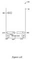
- FIG. 1Ais a block diagram of an illustrative HVAC remote controller 10 that may be used in conjunction with the HVAC system of FIG. 1 .
- the HVAC remote controller 10includes a control module 12 , a wireless interface 14 , a user interface 16 , and one or more sensors 18 .
- the one or more sensors 18may include a temperature sensor, a humidity sensor, a ventilation sensor, an air quality sensor, and/or any other suitable HVAC building control system sensor, as desired.
- the temperature sensormay be provided to sense the temperature proximate the HVAC remote controller 10 .
- the humidity sensormay be provided to sense the humidity proximate the HVAC remote controller 10 .
- the ventilation sensormay be provided to sense the ventilation proximate the HVAC remote controller 10 .
- the one or more sensors 18may be included with the HVAC remote controller 10 , such as within a housing (shown in FIG. 2 ) of HVAC remote controller 10 . However, it is contemplated that one or more sensors 18 may be located remote from the HVAC controller 10 , but in communication therewith, if desired.
- Control module 12 of HVAC remote controller 10may be configured to help control the comfort level (i.e. heating, cooling, ventilation, air quality, etc.) of at least a portion of the building or structure by controlling whether one or more HVAC components 2 of HVAC equipment are activated.
- control module 12may include a processor 20 and a memory 22 .
- Control module 12may be configured to control and/or set one or more HVAC functions, such as, for example, HVAC schedules, temperature setpoints, humidity setpoints, trend logs, timers, environment sensing, and/or other HVAC functions or programs, as desired.
- control module 12may be configured to remotely configure the one or more settings of the HVAC controller, such as, for example, HVAC controller schedules, temperature setpoints, humidity setpoints, trend logs, timers, environment sensing, HVAC controller programs, user preferences, and/or other HVAC controller settings, as desired.
- control module 12may help control the comfort level of at least a portion of the building or structure using the temperature sensed by temperature sensor of the one or more sensors 18 , when provided.
- Memory 22may be used to store any desired information, such as the aforementioned HVAC schedules, temperature setpoints, humidity setpoints, trend logs, timers, environmental settings, and any other settings and/or information as desired.
- Control module 12may store information within memory 22 and may subsequently retrieve the stored information.
- Memory 22may include any suitable type of memory, such as, for example, random-access memory (RAM), read-only member (ROM), electrically erasable programmable read-only memory (EEPROM), Flash memory, or any other suitable memory, as desired.
- RAMrandom-access memory
- ROMread-only member
- EEPROMelectrically erasable programmable read-only memory
- Flash memoryor any other suitable memory, as desired.
- Wireless interface 14 of the HVAC remote controller 10may be configured to wirelessly communicate (i.e. transmit and/or receive signals) with a wireless interface of one or more HVAC controllers 8 (and/or HVAC components 2 ).
- wireless interface 14may be configured to communicate with a wireless interface of HVAC controllers 8 (see FIG. 1 ) to send and/or receive signals that corresponding to, for example, a temperature sensed by temperature sensor, a humidity sensed by the humidity sensor, heat and/or cool set points, ventilation settings, indoor and/or outdoor air temperatures, equipment status, scheduling, trend logs, and/or any other suitable information and/or data.
- the wireless interface 14may include, for example, a radio frequency (RF) wireless interface, an infrared wireless interface, a microwave wireless interface, an optical interface, and/or any other suitable wireless interface, as desired.
- RFradio frequency
- User interface 14may be any suitable interface that is configured to display and/or solicit information as well as permit a user to enter data and/or other settings, as desired.
- user interface 16 of the HVAC remote controller 10may allow a user or technician to program and/or modify one or more control parameters of HVAC remote controller 10 , such as programming, set point, time, equipment status and/or parameters, as desired.
- user interface 16may allow a user or technician to program and/or modify one or more control parameters of the HVAC controller 8 .
- the user interface 16may include a touch screen, a liquid crystal display (LCD) panel and keypad, a dot matrix display, a computer, buttons and/or any other suitable interface, as desired.
- at least some of the parameters and/or settingsmay be transmitted to a HVAC controller 8 via wireless interface 14 .
- FIG. 2is a perspective view of an illustrative HVAC remote controller 24 .
- HVAC remote controller 24may represent a manifestation of HVAC remote controller 10 of FIGS. 1 and 1A , but this is not required.
- the illustrative HVAC remote controller 24includes a display 42 that is disposed within a housing 28 .
- display 42may be at least a portion of the user interface of the HVAC remote controller 24 .
- Display 42may be a touch screen display, a liquid crystal display (LCD) panel, a dot matrix display, a fixed segment display, a cathode ray tube (CRT), or any other suitable display, as desired.
- LCDliquid crystal display
- CRTcathode ray tube
- a dot matrix displayis a typically a LCD display that permits images such as letters, numbers, graphics, and the like to be displayed anywhere on the LCD, rather than being confined to predetermined locations such as is the case with a fixed segment LCD.
- Housing 28may be formed of any suitable material, such as a polymeric, metallic, or any other material, as desired.
- the display 42may be either inset or recessed within the housing 28 as shown.
- the HVAC remote controller 24may be configured to provide substantial display and/or programming functionality.
- FIGS. 3 through 16provide examples of screens that may be displayed by HVAC remote controller 24 during operation.
- the screensmay include a home screen that can be displayed by HVAC remote controller 24 as a default screen, when no other data entry is underway, and/or when selected by the user.
- a home screenmay, if desired, display one or more parameters relating to environmental conditions such as indoor and/or outdoor temperature and/or humidity, expected weather conditions, set points, time, equipment status, and/or any other suitable parameter or setting, as desired.
- the home screenmay vary depending on the HVAC system that the HVAC remote controller 24 is operatively engaged in helping to control (e.g. zone HVAC system, non-zoned HVAC system, programmable HVAC controller, non-programmable HVAC controller, etc.).
- the home screenmay allow many or all of the user settings of the HVAC remote controller 24 to be viewed and controlled, without having to access sub-menus.
- all settings(other than installer setup settings) may be accessed and controlled in a single menu level or screen (e.g. the home screen).
- These settingsmay include, for example, system setting (e.g. heat, cool, off), set point(s), zone selection, clock, indoor temperature, outdoor temperature, etc. It is contemplated that this may be accomplished even when the display 42 is a fixed segment LCD display.
- a HVAC remote controllermay display a home screen that can be used to change an HVAC system setting (e.g.
- the example home screenmay also allow a user to: change whether the HVAC system uses a temperature sensed by the HVAC remote control unit or a separate thermostat; select between two or more zones when the HVAC system is a zoned HVAC system; and/or display one or more temperature readings (e.g. indoor temperature reading and/or outdoor temperature reading), without having to access a sub-menu.
- less used settingssuch as installer setup settings, may be provided in one or more sub-menus or other menus, if desired.
- at least some of the settings for the main user functionality of the HVAC remote controller 24may also be incorporated into one or more sub-menus, if desired.
- FIGS. 3-16are pictorial views showing some illustrative screens that may be displayed on the display 42 of the HVAC remote controller 24 of FIG. 2 .
- HVAC remote controller 24may be configured to display information about one or more HVAC control parameters on at least a portion of a touch screen display 42 .
- remote controller touch screen display 42which may be at least part of the user interface, may include an LCD touch screen display configured to display and/or allow a user to modify one or more parameters or settings. The parameters viewed and/or changes made using touch screen display 42 may be transmitted to and/or received from an HVAC controller 8 .
- touch screen display 42may be a fixed segment display. However, this is not meant to be limiting in any manner and it is contemplated that the touch screen display 42 may be any suitable display, such as, for example, a dot matrix display.
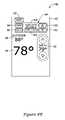
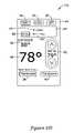
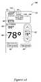
- touch screen display 42may be configured to have a screen 30 that provides the user with information about the operational status of the HVAC controller 8 and/or HVAC remote controller 24 .
- This informationmay include, for example, the current inside temperature 48 , the current outside temperature 46 , the current time 44 , the current heat and/or cool set point 50 , as well as other operational parameters and/or information as desired.
- the HVAC remote controller 24can be configured to access and/or modify various operational settings of the HVAC controller 8 and/or HVAC remote controller 24 .
- the usermay use the touch screen display 42 to adjust the current temperature or humidity setpoints, change the clock or date settings of the HVAC controller 8 and/or HVAC remote controller 24 , change the operational status of the HVAC controller 8 and/or HVAC remote controller 24 (i.e. heat 32 , cool 34 , off 36 ), etc.
- the touch screen display 42may be configured to display the humidity level on a portion of screen 30 .
- touch screen display 42may be configured to display the outdoor humidity level and/or indoor humidity level, as desired.
- touch screen display 42may be configured to display the outdoor humidity level when the user touches the touch screen display adjacent to the current outside temperature 46 .
- touch screen display 42may be configured to display the inside humidity level when the user touches the touch screen display adjacent to the current inside temperature 48 .
- the inside and/or outside humidity levelsmay be displayed for a period of time or, in other cases, may be displayed until the user touches the touch screen display 42 adjacent to the current inside temperature 48 and/or the current outside temperature 42 , respectively.
- any suitable method of displaying the outside and/or inside humidity levelsmay be used, as desired.
- the touch screen display 42may indicate and/or allow a user to set which temperature sensor (e.g. temperature sensor of the HVAC remote controller 10 of FIG. 1A , or a temperature sensor of the HVAC controller 8 ) is currently being used to control the comfort level of the building or other structure.
- touch screen display 42may include an icon 38 for indicating when the temperature sensor of the HVAC controller 8 is currently controlling, and an icon 40 for indicating when the temperature sensor of the HVAC remote controller 10 of FIG. 1A (or HVAC remote controller 24 ) is controlling (e.g. this device).
- touch screen display 42may simultaneously display an icon for each option that a user may wish to select.
- touch screen display 42may include icons 32 , 34 , and 36 , corresponding to the heat mode, cool mode, and off mode, respectively, of the HVAC controller 8 , and icons 38 and 40 for indicating which device's sensed temperature (e.g. the HVAC controller 8 or the HVAC remote controller 10 ), respectively, is currently being used to control the comfort level of the building or other structure.
- the icon corresponding to the selected optionmay include a bold outline, as illustrated by bold outline around icon 38 and icon 32 , and/or a dot or other marker provided within or proximate the outline of the icon, as illustrated by the dot in the relative top left corner of icon 38 and icon 32 . It is contemplated that the option that is currently selected may include a different border, be highlighted, grayed out, or otherwise indicated in any suitable visually discernable manner, as desired.
- a usermay be able to touch the area of the touch screen display 42 that corresponds to icon 32 , 34 , or 36 to manually select and switch the operation status of the HVAC controller 8 , or the area of touch screen display 42 corresponding to icon 38 or 40 to manually select and switch which device's sensed temperature is currently being used to control the comfort level within the building or other structure.
- HVAC remote controller 24may include a backlight operation to illuminate at least a portion of touch screen display 42 .
- the backlightmay be configured to illuminate touch screen display 42 when the user touches a portion of the touch screen display 42 .
- the backlightmay be configured to illuminate the touch screen display 42 for a period of time, such as, for example, one second, two seconds, three seconds, four seconds, five seconds, ten seconds, or any other suitable period of time, as desired. In this case, the period of time may be reset each time the user touches the touch screen display 42 .
- the illustrative HVAC remote controller 24may include one or more backlight operation settings, such as, for example, the brightness, the length of time to illuminate the touch screen display 42 after a touch, and/or any other suitable backlight setting, as desired.
- the HVAC remote controller 24may be configured to activate the backlight to illuminate the touch screen display 42 when the user touches any portion of the touch screen display 42 .
- the HVAC remote controller 24may be configured to illuminate the touch screen display 42 only when a predetermined portion of the touch screen display 42 is touched, such as, for example, the corners of the touch screen display 42 , a portion of the touch screen display 42 that does not correspond to any icon, or any other suitable portion, as desired.
- the HVAC remote controller 24may be configured to include a button to activate and/or deactivate the backlight display on the housing 28 of the HVAC remote controller 24 , but this is not required.
- the touch screen display 42may be configured to illuminate the backlight when the user touches the touch screen display 42 .
- the touch screen display 42When the touch screen display 42 is illuminated, the user may then be able to view, control, and/or adjust the one or more parameters of the HVAC remote controller 24 .
- the HVAC remote controller 24may be configured to prevent any parameter or setting changes to the HVAC remote controller 24 when the touch screen display 42 is not illuminated by the backlight, but this is not required.
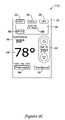
- the screen 30may correspond to a home screen for the HVAC remote controller 24 .
- screen 30may represent a home screen when, for example, the HVAC remote controller 24 is operatively coupled to a programmable HVAC controller 8 in a non-zoned HVAC system.
- screen 30 of the touch screen display 42may provide HVAC operational status, such as, the current inside temperature 48 , the current outside temperature 46 , the current time 44 , and the current heat and/or cool set point 50 .
- screen 30may indicate which device's temperature sensor is currently being used to control the comfort level within the building or other structure.
- screen 30may provide the operational status of the HVAC control system (e.g. heat, cool, off, etc.).
- touch screen display 42may include an icon 32 for indicating when the HVAC controller 8 is in heat mode, an icon 34 for indicating when the HVAC controller 8 is in cool mode, and an icon 36 for indicating when the HVAC controller 8 is in an off mode.
- icon 32for indicating when the HVAC controller 8 is in heat mode
- icon 34for indicating when the HVAC controller 8 is in cool mode
- icon 36for indicating when the HVAC controller 8 is in an off mode.
- the operational status of the HVAC controller 8is shown to be in the heat mode.
- a usermay be able to touch the area of the touch screen display 42 corresponding to icon 32 , 34 , or 36 to manually switch the operational status of the HVAC controller 8 , if desired.
- screen 30may change to either screen 52 or 54 , shown in FIGS. 3B and 3C , respectively.
- the set point shown as the current heat and/or cool set point 50may be changed by touching the region of the touch screen display 42 that corresponds to the up arrow and/or the down arrow shown above and below the heat and/or cool set point 50 . If the set point is changed, the touch screen display 42 may display, for example, screen 92 shown in FIG. 8A .
- the illustrative HVAC remote controller 24may be configured to include an auto operational mode.
- the auto modemay be set, or switched to, by touching the touch screen display 42 corresponding to both icon 32 and icon 34 simultaneously. In some cases, the touch may have to last for a period of time, but this is not required. If the operational mode is switched to auto mode, the touch screen display 42 may display screen 142 shown in FIG. 11A . Alternatively, it is contemplated that a separate “auto” mode button may be provided on the touch screen display 42 , which can then be directly selected by the user.
- the HVAC remote controller 24may be configured to detect a power level, such as, for example, a remaining battery power level. If the remaining battery power level detected by the HVAC remote controller 24 is less than a threshold level, in some cases, the touch screen display 42 may display screen 76 or 80 shown in FIG. 6A or 6 B, respectively, which displays a “Replace Battery” indicator.
- the HVAC remote controllermay be configured to wirelessly communication with one or more HVAC controllers 8 and/or HVAC components 2 .
- the wireless communication signalsuch as, for example, a radio frequency (RF) signal
- RFradio frequency
- FIG. 3Bshows an illustrative screen 52 that may be displayed on the touch screen display 42 when the operational status of the HVAC controller is turned to the off mode.
- screen 52may be similar to screen 30 shown in FIG. 3A , providing parameters such as, the current inside temperature 48 , the current outside temperature 46 , the current time 44 , the controlling device (e.g. which temperature sensor is currently being used to control the comfort level of the building or other structure), and the operational status of the HVAC control system (e.g. heat, cool, off).
- icon 36 corresponding to the off modemay include a bold outline and/or dot, or may include a different border, be highlighted, grayed out, or otherwise indicate that the HVAC controller is set to the off mode.
- the current heat and/or cool set pointshown as 50 of FIG. 3A , may be removed from screen 52 .
- FIG. 3Cshows an illustrative screen 54 of touch screen display 42 when the operational status of the HVAC controller is turned to cool mode.
- screen 54may be similar to screen 30 and 52 shown in FIGS. 3A and 3B , respectively, providing parameters, such as, the current inside temperature 48 , the current outside temperature 46 , the current time 44 , the controlling device (e.g. which temperature sensor is currently being used to control the comfort level of the building or other structure), and the operational status of the HVAC control system (e.g. heat, cool, off).
- the controlling devicee.g. which temperature sensor is currently being used to control the comfort level of the building or other structure
- the operational status of the HVAC control systeme.g. heat, cool, off.
- the icon 34 corresponding to the cool modemay include a bold outline and/or dot, may include a different border, may be highlighted, grayed out, or otherwise indicated that the HVAC controller is set to the cool mode.
- the current heat and/or cool set point, shown at 50may be provided on the screen 54 .
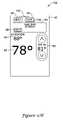
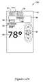
- FIGS. 4A-4Dare pictorial views showing illustrative screens 56 , 66 , 68 , and 72 that may be displayed on the illustrative HVAC remote controller touch screen display 42 for setting/changing zones, when present.
- the HVAC remote controller 24may be used in a multi-thermostat building control system and/or a zoned HVAC control system.
- illustrative screen 56 shown in FIG. 4Amay be used as a home screen for a zoned HVAC system, but this is not required.
- Screen 56provides parameters related to HVAC operational status including, for example, the current inside temperature 48 , the current outside temperature 46 , the current time 44 , and the current heat and/or cool set point 50 .
- screen 56may provide the operational status of the HVAC control system.
- touch screen display 42may include an icon 32 for indicating when the HVAC controller is in heat mode, an icon 34 for indicating when the HVAC controller is in cool mode, and an icon 36 for indicating when the HVAC control is off.
- the icon that corresponds to the current operational status of the HVAC systemmay include a bold outline, as illustrated by bold outline around icon 32 , and/or a dot within the icon, or may include a different border, may be highlighted, grayed out, or otherwise differentiated from the other operational status icons.
- a usermay be able to touch the area of the touch screen display 42 corresponding to icon 32 , 34 , or 36 to manually switch the operational status of the HVAC system.
- screen 56may include an indication of which device (e.g. which temperature sensor is currently being used to control the comfort level of the building or other structure) is controlling the HVAC controller, if desired.
- screen 56may include an HVAC zone navigation area 58 for indicating and/or navigating through the various zones of the building or other structure.
- the navigation area 58may include a room indicator 64 and two directional arrows, shown as icons 60 and 62 , for scrolling or toggling through the one or more available zones in the building or other structure.
- the HVAC remote controller 24is currently identifying the “LIVING ROOM” zone, as shown by room indicator 64 .
- the HVAC remote controller 24may display, set and/or control parameters related to the living room zone of the building or other structure.
- a usermay touch the left directional arrow icon 60 or right directional arrow icon 62 . Touching the icons 60 or 62 may scroll or toggle through the available zones in the building or other structure.
- the touch screen display 42may switch from screen 56 to screen 66 , shown in FIG. 4B .
- the HVAC operational statussuch as, the current inside temperature 48 , the current outside temperature 46 , the current time 44 , the current heat and/or cool set point 50 , and the current operational status (e.g. heat 32 , cool 34 , and off 36 ) may be removed from screen 66 , but this is not required.
- the room indicator 64 displaymay change from the “LIVING ROOM” zone to a “BEDROOM 1” zone.
- the room indicator 64may correspond to any number of rooms, such as, for example, “KITCHEN”, “DEN”, “FAMILY ROOM”, “BASEMENT”, “BEDROOM 2”, “BEDROOM 3”, “BEDROOM 4”, “BATHROOM”, “DINING ROOM”, “STUDY”, or any other suitable zone, as desired.
- Multiple touches of the icons 60 and/or 62may cause the room indicator 64 to display a third zone, a fourth zone, a fifth zone, and so on to scroll or toggle through the available zones.
- the zone identified by room indicator 64may be selected and the HVAC remote controller 24 may display screen 68 on the touch screen display as shown in FIG. 4C .
- the predetermined timemay be about 1.5 seconds. However, it is contemplated that any predetermined time may be used, such as, for example, one second, two seconds, three seconds, four seconds, five seconds, ten seconds, or any other amount of time, as desired.
- screen 66may include an icon (not shown) that the user may touch to indicate that the user is done. For example, screen 66 may include a “Done” icon and, in some cases, a “Cancel” icon to cancel the change, if desired.
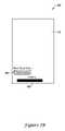
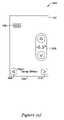
- screen 68 shown in FIG. 4Cmay display a loading indicator 70 , or activity indicator, along with the room indicator 64 , indicating that the currently selected zone is being loaded onto the HVAC remote controller 24 .
- loading indicator 70may include the text “loading” and/or may include a status progress bar, and/or may include any other suitable mechanism for indicating that the currently selected zone is being loaded.
- the loading indicator 70 and/or progress barmay indicate to a user that the HVAC remote controller 24 is busy, such as, for example, attempting to establish a wireless communication with the HVAC controller 8 .
- “BEDROOM 1”is displayed indicating that the HVAC remote controller 24 is switching to the BEDROOM 1 zone.
- the HVAC remote controller 24is attempting to wirelessly communicate with the HVAC controller 8 of the selected zone, which, in some cases, may be through RF or other signals. If parameters related to the desired zone are successfully loaded, screen 72 , shown in FIG. 4D , may be displayed on the touch screen display 42 .
- the HVAC remote controller 24may provide for a predetermined loading period of time. In this case, if the HVAC remote controller 24 successfully establishes communication and successfully loads the parameters for the selected zone, screen 72 may be displayed. If, however, communication cannot be established between the HVAC remote controller 24 and the HVAC controller 8 of the selected zone within the predetermined loading period of time, screen 180 of FIG. 14C may be displayed.
- the predetermined loading period of timemay be on the order of seconds or minutes, depending on the installation and HVAC controller. In one example case, the predetermined loading period of time may be about 7 second. Additionally, in some cases, any hold and/or auto information, which will be discussed below, may be removed from the touch screen display 42 when the new zone is loading on the HVAC remote controller 24 , if desired.
- Screen 72 of FIG. 4Dmay be similar to screen 56 shown in FIG. 4A , except that the room indicator 64 may correspond to a different zone of the building or other structure. For example, “LIVING ROOM” was displayed on screen 56 and “BEDROOM 1” is displayed on screen 72 .
- the HVAC remote controller 24may automatically select a corresponding zone, as the HVAC remote controller 24 is carried through the building or other structure.
- the HVAC remote controller 24may include a signal strength indicator that measures the signal strength from each of the identified HVAC zone controllers 8 . The HVAC remote controller 24 may then automatically select the HVAC zone controller 8 that produces the highest signal strength.
- each zonemay include a zone ID device that, when the HVAC remote controller 24 is in the proximity of a zone ID device, the zone ID device informs the HVAC remote controller 24 which zone that the HVAC remote controller 24 is currently in. The HVAC remote controller 24 may then automatically select the appropriate zone.
- the usermay alter the settings for the zone via the user interface of the HVAC remote control unit.
- the one or more changed parameters and/or settingsmay then be sent to the zoned HVAC system via the wireless interface, wherein the zoned HVAC system may subsequently operate in accordance with the one or more changed parameters and/or settings in the selected zone.
- the parameters and/or settingsmay be loaded from and sent to one or more wall mounted thermostats, if desired.
- the HVAC remote control unitmay be configured to automatically detect and establish communication with each of two or more wall mounted thermostats either simultaneously, sequentially or by user selection, if desired.
- the HVAC remote control unitmay be configured to dynamically change its behavior based on whether it detects a non-zoned or a zoned HVAC system. For example, if a non-zoned HVAC system is detected, the HVAC remote control unit may not display HVAC zone navigation area 58 , and may control the HVAC system in accordance with an algorithm for a non-zoned HVAC system. Likewise, if a zoned HVAC system is detected, the HVAC remote control unit may display HVAC zone navigation area 58 , and may control the HVAC system in accordance with an algorithm for a zoned HVAC system. In some cases, and for zoned HVAC systems, the behavior of the HVAC remote control unit may automatically change depending on the number of wireless thermostats that are detected.
- the HVAC remote control unitmay allow a user to navigate to each of the detected zones via HVAC zone navigation area 58 , and may use an appropriate control algorithm (e.g. 2 zone algorithm, 3 zone algorithm, 4 zone algorithm, etc.) depending on the number of detected zones.
- an appropriate control algorithme.g. 2 zone algorithm, 3 zone algorithm, 4 zone algorithm, etc.
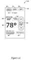
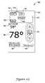
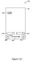
- FIG. 5is a pictorial view showing a screen 74 that may be displayed on the illustrative HVAC remote controller 24 touch screen display 42 .
- Screen 74may be displayed as a home screen for the HVAC remote controller 24 when, for example, the HVAC remote controller 24 is operatively coupled to a non-programmable HVAC controller in a non-zoned HVAC system.
- screen 74may provide HVAC operational status, such as, the current inside temperature 48 , the current outside temperature 46 , the current heat and/or cool set point 50 , the current operational status of the HVAC controller (e.g. heat 32 , cool 34 , and off 36 ), and the device whose temperature sensor is currently controlling the HVAC controller (e.g. thermostat 38 , this device 40 ).
- HVAC operational statussuch as, the current inside temperature 48 , the current outside temperature 46 , the current heat and/or cool set point 50 , the current operational status of the HVAC controller (e.g. heat 32 , cool 34 , and off 36 ), and the device whose temperature sensor is currently controlling the
- screen 74may include a bold outline and/or dot to indicate the current operational status and/or device controlling the comfort level of the building.
- icon 32has a bold outline and dot indicating that the HVAC controller 8 is currently in heat mode
- icon 38has a bold outline and dot indicating that the temperature sensor of the HVAC controller 8 (e.g. Thermostat) is currently being used to control the comfort level of the building or other structure.
- screen 74may include the current time and/or other parameters if the HVAC controller 8 or other device in wireless communication with the HVAC remote controller 24 supports such parameters.
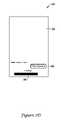
- FIG. 6Ais a pictorial view showing an illustrative screen 76 that may be displayed on the illustrative HVAC remote controller touch screen display 42 when the HVAC remote controller 24 detects a low battery condition.
- the HVAC remote controller 24is a portable hand held device, and may be powered by one or more local power sources such as batteries. If the control module 12 of the HVAC remote controller 10 detects that the battery is getting low, such as, for example, providing a voltage that is below a threshold voltage, the HVAC controller 10 may display screen 76 . As illustrated, screen 76 may be similar to screens discussed previously with the addition of a low battery indicator 78 . In some cases, the low battery indicator 78 may be displayed when the battery level is below a low battery threshold level.
- the low battery threshold levelmay be 10%, 15%, 20%, 25%, 30%, or 50% of the battery life remaining. However, it is contemplated that any suitable low battery threshold may be used, as desired. As illustrated, the low battery indicator 78 displays the text “Replace Battery” on the touch screen display 42 . However, it is contemplated that a battery icon may be displayed or any other suitable low battery indicator may be displayed, as desired. In some cases, the low battery indicator 78 may flash on and off at a rate, such as, for example, a rate of one second.
- screen 80 of FIG. 6Bmay be displayed on the touch screen display 42 of the HVAC remote controller 24 .
- all (or at least some) of the displayed parameters and informationmay be removed from the touch screen display with the exception of the low battery indicator 78 .
- the low batter indicator 78may flash, but this is not required.
- the critical low battery thresholdmay be 2%, 5%, 7%, 10% of remaining battery life, or any other suitable remaining battery life less than the low battery threshold discussed with reference to FIG. 6A , as desired.
- FIGS. 7A-7Dare pictorial views showing illustrative screens that may be displayed on the HVAC remote controller touch screen display 42 to change which temperature sensor is currently being used to control the comfort level of the building or other structure.
- the screen 82 displayed on the touch screen display 42may be similar to home screens discussed previously, such as, for example, screen 30 of FIG. 3A .
- screen 82includes an icon 38 for indicating when a temperature sensor of the HVAC controller 8 is controlling the comfort level of the building, and an icon 40 for indicating when the temperature sensor of the HVAC remote controller 14 (shown in FIG. 1 ) is controlling the comfort level of the building.
- the icon corresponding to the controlling devicemay include a bold outline, as illustrated by bold outline around icon 40 , and/or a dot within the icon, or may include a different border, may be highlighted, grayed out or otherwise visually indicated, as desired.
- a usermay touch the area of the touch screen display 42 corresponding to icon 38 or 40 to manually select and switch which device's temperature sensor is controlling the comfort level of the building.
- the HVAC controller 8 and/or HVAC remote controller 24may include a control algorithm that automatically switches control from one device to the other. For example, if the temperature sensed by the temperature sensor of the HVAC remote controller 24 differs from the temperature sensor of the HVAC controller 8 by more than a threshold amount and/or for a threshold period of time, control may automatically switch from the HVAC remote controller 24 to the HVAC controller 8 . Such a temperature differential may occur when, for example, the user is holding the HVAC remote controller 24 in his/her hand, when the HVAC remote controller 24 is set down next to an open door or window, set down outside, and/or set down in direct sun light. This is just one examples of when control may automatically switch from the HVAC remote controller 24 to the HVAC controller 8 .
- the temperature sensor of the HVAC remote controller 24is currently being used to control the comfort level of the building or other structure.
- the temperature controlmay be switched to use the temperature sensor of the HVAC controller 8 .
- screen 84may be displayed. Screen 84 may show a loading progress bar 86 and icon 38 , indicating that control is being switched to the HVAC controller 8 .
- a data exchange between the HVAC controller 12 and the HVAC remote controller 24may take place during this time period.
- the updated datacan include any suitable data including updated set points, updated sensed temperature readings, updated sensed humidity readings, updated system status information, updated operational data and/or other data, as desired. In some cases, this may take up to 20 seconds or more. In other cases, shorter transmit times are contemplated, including nearly instantaneously.
- the touch screen display 42may display a screen 88 , which is similar to screen 82 shown in FIG. 7A , but with icon 38 indicating that the temperature sensor of the HVAC controller 8 (e.g. thermostat) is now controlling instead of the temperature sensor of the HVAC remote controller 24 (e.g. this device). Also, and in some cases, updated set point, sensed temperature, sensed humidity, system status and/or other data may also be displayed, if desired.
- the temperature sensor of the HVAC controller 8e.g. thermostat
- updated set point, sensed temperature, sensed humidity, system status and/or other datamay also be displayed, if desired.
- the usermay touch the touch screen icon 40 to switch control back to the temperature sensor of the HVAC remote controller 24 .
- a progress bar 86 and icon 40may be displayed on the screen 90 , in a manner similar to that described above.
- the HVAC remote controller 24may include a predetermined timeout period where, if the HVAC remote controller 24 is unable to establish wireless communication with a HVAC controller 8 , the HVAC remote controller 24 may display a “No Signal” screen, similar to screen 174 of FIG. 14A .
- the predetermined timeout periodmay be 5, 10, 20, 30, 60 seconds, or any other suitable time period, as desired. In one example, the predetermined timeout period may be about 7 seconds.
- the touch screen display 42may not register any touches by a user, but this is not required.
- FIGS. 8A-8Eare pictorial views showing illustrative screens that may be displayed on the illustrative HVAC remote controller touch screen display 42 to change the heat and/or cool set point 50 and/or to program a temperature hold.
- the usermay not be able to initiate a temperature hold with the HVAC remote controller 24 .
- touch screen display 42may display screen 92 when the touch screen display 42 detects a touch corresponding to the up or down arrow of the current heat and/or cool set point 50 in, for example, a home screen such as home screen 30 (see FIG. 3A ).
- the usermay adjust the heat and/or cool set point 50 by touching the up arrow and/or down arrow on the touch screen display 42 .
- the set pointmay increase or decrease by one degree when a touch is detected.
- the screen 92displays a set point temperature of 79 degrees, which is one degree higher than, for example, the set point of 78 degrees shown for the home screen 30 in FIG. 3A .
- the usermay have touched the touch screen display 42 adjacent to the up arrow of the current heat and/or cool set point 50 one time.
- screen 92may provide a hold display region 94 when the set point is adjusted.
- a temperature holdmay be initiated by a user to maintain a desired hold temperature set point for a period of time, regardless of the current set point of a previously programmed temperature schedule.
- the hold display region 94may include a border defining the region, but this is not required.
- the illustrative hold display region 94may include a “hold until” display with a time indicating the time at which the hold temperature should end. For example, as illustrated, the hold time may end at 10:00 AM.
- the usermay be able to adjust the hold end time by touching the touch screen display 42 adjacent to icon 100 , which may include an up arrow for increasing the time, or by touching the touch screen display 42 adjacent to icon 102 , which may be a down arrow for decreasing the time.
- screen 108 shown in FIG. 8Bmay be displayed.
- the hold until timehas changed from 10:00 AM to 10:15 AM.
- the usermay continue to adjust the hold time until a desired hold end time is displayed.
- the hold end timemay be changed in 15 minute increments, however, this is merely illustrative and any time increments may be used, as desired.
- Icon 96may be a done icon that may set or program the hold operation in the HVAC remote controller 8 .
- the hold operationmay be properly setup when the user touches the done icon 96 , and/or when screens 92 or 108 timeout when touch screen display 42 does not detect a touch within a period of time.
- the period of time for the timeoutmay be on the order of seconds, such as, for example, three, four, five, ten, or more seconds, or on the order of minutes. However, it is contemplated that any other suitable timeout may be used, as desired.
- the hold operationmay be communicated to a corresponding HVAC controller 8 , which may then control the corresponding HVAC components 2 accordingly.
- Icon 98may be used to cancel the hold operation request and return to, for example, the home screen 30 of FIG. 3A .
- the screen 110 of FIG. 8Cmay be displayed.
- screen 110may be similar to screens 92 and 108 with the difference of having icons 96 , 100 , 102 , and 104 removed from the touch screen display 42 .
- the HVAC remote controller 24may be configured to display the hold options when a touch is sensed by the touch screen display 42 .
- the detected touchmay need to be in the hold display region 94 , but this is not required.
- the temperature hold operationmay expire when the HVAC remote controller 24 and/or HVAC controller 8 determines that the current time is the same as the “hold until” time. In this case, when the hold operation expires, the HVAC remote controller 24 may return to its previously programmed settings and/or schedule. In some cases, this may cause the touch screen display 42 to display the appropriate home screen, such as, for example, home screen 30 of FIG. 3A .
- an icon 104 corresponding to a permanent holdmay be provided.
- a touch of icon 104may set a permanent temperature hold of the HVAC remote controller 24 and/or HVAC controller 8 .
- a permanent holdmay set the heat and/or cool set point 50 to a set temperature until the user manually cancels or terminates the permanent hold operation.
- the permanent temperature holdmay not include the time element (e.g. an end time) of the previously described temporary hold operation.
- the HVAC remote controller 24may display touch screen 112 , shown in FIG. 8D .
- hold display region 94displays icon 98 corresponding to a cancel button.
- a touch of icon 98may cancel the permanent hold operation.
- the current time 44may be displayed along with a permanent hold indicator 107 in the hold display region 94 .
- the permanent hold indicator 107includes the text “PERM. HOLD”. However, it is contemplated that any suitable indicator may be used, as desired.
- the usermay modify the current permanent hold set points and/or other options.
- the usermay touch the touch screen display 42 adjacent to the “CANCEL” icon 98 . In some cases, this ends the permanent hold operation and returns the touch screen display 42 to a home screen, such as, for example, home screen 30 of FIG. 3A .
- the usermay touch the touch screen display 42 adjacent to the cool icon 34 .
- the HVAC controllermay switch its operational status to the cool mode, indicated by the bold outlined icon 34 and dot within icon 34 shown in screen 114 of FIG. 8E , but may retain the permanent hold set point and/or other settings.
- the permanent holdmay be canceled and/or terminated when the user changes the operational status of the HVAC controller 8 , if desired.
- FIGS. 9A-9Eare pictorial views showing illustrative screens that may be displayed on the touch screen display 42 of an illustrative HVAC remote controller 24 , including a screen lock indicator.
- the illustrative HVAC remote controller 24can be configured to lock and unlock the touch screen display 42 (or portions thereof) to help reduce the chance of accidental changes to the operation and/or settings of the HVAC remote controller 24 and/or HVAC controller 8 .
- the HVAC remote controller 24may include a setup menu routine, as will be discussed below with reference to FIGS. 15D-15G , which may include an option to enable or disable such a screen lock function.
- screen 116may include the current inside temperature 48 , the current outside temperature 46 , the current time 44 , the current heat and/or cool set point 50 , the current operational status of the HVAC controller (e.g. heat 32 , cool 34 , and off 36 ), and the current device used for controlling the temperature of the HVAC comfort control system (e.g. HVAC controller icon 38 , or this device icon 40 ).
- screen 116may include an icon 118 indicating that the screen is currently unlocked.
- icon 118includes the text “SCREEN UNLOCK”.
- any suitable icon or indicator that indicates that the screen is currently unlockedmay be used, such as, for example, a graphical image of a lock in the unlocked position.
- a usermay touch icon 118 .
- the HVAC remote controller 24may be configured to require continuous touching of the icon 118 for a period of time, such as, for example, 3 seconds to lock the display.
- the HVAC controllermay be configured to lock the touch screen display upon detection of the user touching icon 118 and, in some cases, the HVAC controller 8 may wait a period of time before locking the touch screen display 42 , such as, for example, one second, two seconds, three seconds, four seconds, five seconds, ten seconds, or any other suitable period of time, as desired.
- icon 118may be replaced by icon 132 , which may include the text “SCREEN LOCKED” or some other suitable indicator, such as, for example, a graphical image of a lock in a locked position.
- icon 132may include the text “SCREEN LOCKED” 122 on a portion of the display, such as the lower portion of the display.
- the illustrative screen 120may only be displayed for a relatively short period of time, on the order of seconds, after the HVAC controller locks the screen.
- screen 120may only be shown on the touch screen display 42 when the HVAC remote controller 24 is configured to require a continuous touching for a period of time, but this is not required.
- touch screen display 42may display screen 124 shown in FIG. 9C in the illustrative embodiment.
- Screen 124is similar to screen 116 of FIG. 9A , except that screen unlocked icon 118 is replaced by screen locked icon 132 .
- the touch screen display 42may not register any user touches, except to unlock the touch screen display 42 .
- the screenmay be unlocked by, for example, touching the screen locked icon 132 and, in some cases, holding the screen locked icon 132 for a period of time.
- the period of timemay be 1, 2, 3, 4, or 5 seconds. However, any suitable period of time may be used, as desired.
- the screenmay be unlocked by simultaneously touching two different regions of the display 42 for a period of time, such as two corners of the display.
- the displaymay include an interface that allows a user to enter a password, and the screen is unlocked once an appropriate password has been entered.
- the screen locked icon 132may flash once or a number of times at a rate. In some cases, the flashing rate may be one-half a second, one second, or any other flash rate, as desired. In some cases, the “SCREEN LOCKED” text of screen 120 may be displayed, and may also flash.
- screen locked icon 132may be replaced by screen unlocked icon 118 .
- “SCREEN UNLOCKED”may be provided on a portion of the touch screen display 42 , such as a lower portion of the display 42 .
- the illustrative screen 126may only be displayed for a relatively short period of time, on the order of seconds, when the HVAC remote controller 24 first unlocks the screen.
- screen 130 shown in FIG. 9Emay be displayed.
- screen 130may be the same as screen 116 of FIG. 9A , but this is not required in all embodiments.
- FIGS. 10A and 10Bare pictorial views showing illustrative vacation hold screens 134 and 140 that may be displayed on the touch screen display 42 of an illustrative HVAC remote controller 24 .
- FIG. 10Ais an illustrative screen 134 that may be displayed when a vacation hold is set when the HVAC controller 8 is operating in heat mode.
- the vacation holdmay only be programmed through the HVAC controller 8 , and the touch screen display 42 of the HVAC remote controller 24 only displays the status of the HVAC controller 8 .
- the vacation holdmay be programmed via the HVAC remote controller 24 , similar to the temperature hold and/or permanent temperature hold operations discussed above.
- screen 134may show the current inside temperature 48 , the current outside temperature 46 , the current time 44 , the current heat set point without up or down arrows 136 , the current operational status of the HVAC controller (e.g. heat 32 , cool 34 , and off 36 ), and the current device used for controlling the temperature of the HVAC comfort control system.
- the current operational status iconis displayed (e.g. heat mode 32 ), and not the other unselected options (cool mode, off mode).
- the HVAC controlleris in heat mode
- only icon 32is displayed, and when the HVAC controller is in cool mode, as shown in FIG. 10B , only icon 34 is displayed.
- screen 134may only display the icon for the device that is currently controlling the temperature of the building, such as, for example, icon 38 when the temperature sensor of the HVAC controller 8 (e.g. thermostat) is controlling.
- a vacation indicator 138may also be displayed, indicating that the HVAC controller 8 is in vacation hold mode.
- “VACATION HOLD”may be displayed on at least a portion of the touch screen display 42 , such as a lower portion of the display 42 .
- any suitable indicatormay be used at any suitable location, when provided.
- FIG. 10Bshows an illustrative screen 140 that may be displayed when a vacation hold is set with the HVAC controller 8 in cool mode. Screen 140 is similar to screen 134 of FIG. 10A , except the cool icon 34 is shown instead of heat icon 32 .
- FIGS. 11A-11Nare pictorial views showing illustrative screens that may be displayed on an illustrative HVAC remote controller touch screen display 42 for setting/changing an auto mode of the HVAC controller 8 and/or HVAC remote controller 24 .
- the touch screen display 42may include the current time 44 , the current outdoor temperature 46 , the current inside temperature 48 , the current head and/or cool set point 50 , and the current device used to control the temperature of the comfort control system.
- heat mode icon 32 and cool mode icon 34may be displayed with “AUTO” text above the icons 32 and 34 as shown.
- the auto modemay be entered via the HVAC remote controller 24 by detecting a touch of the touch screen display 42 corresponding to both the heat icon 32 and the cool icon 34 for a period of time.
- the period of timemay be one second, two seconds, three seconds, four seconds, five seconds, or any other suitable time period, as desired.
- the usermay touch the touch screen display 42 corresponding to both the heat icon 32 and cool icon 34 for the period of time.
- a separate “auto” mode icon(not shown) may be provided on the display, which when touched, switches to the auto mode.
- the touch screen display 42may display a home screen, such as, for example, home screen 30 shown in FIG. 3A .
- the usermay view the set points 50 of both the heat and cool modes. As illustrated on screen 142 of FIG. 11A , the user may view the heat set points. To view the cool set points, the user may touch the touch screen display 42 adjacent to the cool icon 34 . Then, screen 146 shown in FIG. 11B may be displayed on the touch screen display 42 . As illustrated, the current outdoor temperature 46 , the current indoor temperature 48 , and the current cool set point 50 may be displayed on screen 146 . In some cases, icon 34 may include a bold outline even though the HVAC remote controller is in heat mode. The heat mode may be indicated by the dot that remains within heat mode icon 32 . After a period of time, touch screen display 42 may display screen 148 of FIG. 11C , which is similar to screen 142 if FIG. 11A showing the current heat set point 50 .
- FIG. 11Dis a pictorial view showing a screen 150 that can be displayed on the touch screen display 42 to change the current set point 50 while in auto mode.
- the touch screen display 42may monitor the touch screen adjacent to the current set point 50 for a touch.
- hold display region 94may be displayed, similar to that discussed above with reference to FIG. 8A .
- hold display region 94may include a hold until time 106 , a done icon 96 , a cancel icon 98 , an up arrow icon 100 , a down arrow icon 102 , and a permanent hold icon 106 .
- the usermay adjust the hold settings, such as, for example, the hold until time, set a permanent hold, or the user may continue to adjust the set point 50 .
- the desired hold settingis displayed, the user may touch the touch screen adjacent to the done icon 96 or may wait until the touch screen display 42 times out.
- screen 152 shown in FIG. 11Emay be displayed.
- cancel icon 98may be touched to return the touch screen display 42 to show, for example, screen 142 of FIG. 11A .
- FIGS. 11F-11Kare pictorial views showing illustrative screens for changing the cool set point and/or other settings when the HVAC controller 8 is in auto-heat mode.
- Screen 154 shown in FIG. 11Fmay be displayed on the touch screen display 42 when, from screen 152 of FIG. 11E , the touch screen display 42 is touched adjacent to the cool icon 34 .
- screen 154shows the current set points and/or other settings of the cool mode, similar to screen 146 of FIG. 11B , with the addition of the hold display region 94 .
- the usermay touch the touch screen corresponding to either the up arrow or down arrow of cool set point 50 .
- 11Gmay be displayed on the touch screen display 42 . While screen 156 is displayed, the cool set point 50 may be adjusted to a desired set point. Screen 156 may be removed from the touch screen display by detecting a touch of the touch screen 42 corresponding to icon 96 (DONE) or if no touch is detected on the touch screen display 42 and the HVAC remote controller 24 timeout period expires.
- screen 158 shown in FIG. 11Hmay be displayed on touch screen display 42 .
- screen 158may be similar to screen 154 of FIG. 11F , showing the cool set point and/or other settings, but with the modified cool set point temperature 50 .
- the screenmay timeout after a period of time.
- a touch of the up arrow and/or down arrowmay return to screen 156 of FIG. 11G to allow for further changes.
- screen 160 of FIG. 11Imay be displayed on the touch screen display 42 .
- the illustrative screen 160may display the heat mode and current settings of the HVAC remote controller 24 , similar to screen 152 of FIG. 11E .
- the HVAC remote controller 24may communicate with the one or more HVAC controllers 8 to upload and/or download current HVAC controller settings and/or parameters. In some cases, this data transfer may last seconds or minutes.
- touch screen display 42may display screen 162 , shown in FIG. 11J , illustrating the current cool settings.
- screen 164 shown in FIG. 11Kmay be displayed. As illustrated, screen 164 may be the same as screen 160 showing the current mode and settings of the HVAC remote controller.
- FIGS. 11L-11Nare illustrative screens showing the HVAC remote controller 24 requesting cool mode set points from an HVAC controller 8 when in heat mode.
- the HVAC controller 8may be set in auto heat mode, as indicated by “AUTO” 144 and the bold outline and dot of icon 32 . Additionally, the heat set point may have been adjusted, as indicated by the hold display region 94 .
- screen 192 shown in FIG. 11Mmay be displayed on touch screen display 42 .
- screen 192may include a loading bar 86 indicating that the HVAC remote controller 24 is attempting to communicate with the HVAC controller 8 .
- this communicationmay be to upload and/or download cool mode set points, parameters, and/or other settings. In some cases, the communication may last for seconds or for minutes, depending on the application.
- screen 194 shown in FIG. 11Nmay be displayed on touch screen display 42 .
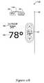
- FIG. 12is pictorial view showing illustrative emergency (EM) heat mode screens 168 that may be displayed on the touch screen display 42 of an illustrative HVAC remote controller 24 .
- an emergency heat modemay activate a second heat stage, or backup or supplemental heating, when a heat pump (or other heat source) is unable to provide sufficient heating to the building or other structure.
- the EM heat modemay only be programmed through the HVAC controller 8 and, in this case, the touch screen display 42 of the HVAC remote controller 24 may only display the status of the HVAC controller 8 . Additionally, in some cases, EM heat mode may only be exited via the HVAC controller 8 . However, it is contemplated that, in some cases, the EM heat mode may be entered and exited via the HVAC remote controller 24 , if desired.
- screen 168may include the current inside temperature 48 , the current outside temperature 46 , the current time 44 , the current heat and/or cool set point 50 , and the current device used for control of the HVAC comfort control system (e.g. HVAC controller icon 38 , or HVAC remote controller icon 40 ).
- the current device used for control of the HVAC comfort control systeme.g. HVAC controller icon 38 , or HVAC remote controller icon 40 .
- icon 167may be displayed indicating that the HVAC controller is in EM heat mode.
- FIG. 13is pictorial view showing an illustrative “southern away” hold screen 170 that may be displayed on the touch screen display 42 of an illustrative HVAC remote controller 24 .
- a southern away holdmay be an extended hold that may provide appropriate heating or cooling to, for example, maintain the temperature and/or humidity levels below threshold values, as desired. This may help prevent excessive heat and/or moisture to buildup in a building or other structure, such as when the occupants of the house are away for an extended period of time.
- a southern away holdmay only be programmed and/or entered through the HVAC controller 8 and, in this case, the touch screen display 42 of the HVAC remote controller 24 may only display the status of the HVAC controller 8 .
- southern away holdmay only be exited via the HVAC controller 8 .
- a southern away holdmay be entered and exited via the HVAC remote controller 24 , such as, for example, similar to the temporary hold and permanent temperature hold operations discussed previously.
- screen 170 of FIG. 13may include the current inside temperature 48 , the current outside temperature 46 , the current time 44 , the current heat and/or cool set point 50 , the current device used for control of the HVAC comfort control system (e.g. HVAC controller icon 38 , or HVAC remote controller icon 40 ), and the current operational status icon.
- the operational status of the HVAC controller 8may be in the cool mode when in the southern away hold and, as such, screen 170 may include cool mode icon 34 .
- the touch screen display 42may also include a southern away indicator 172 on at least a portion of the touch screen display 42 , such as a lower portion of the display 42 .
- the southern away indicatormay include the text “SOUTHERN AWAY”, but it is contemplated that any suitable indicator may be provided, as desired.
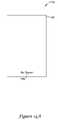
- FIGS. 14A-14Dare pictorial views showing illustrative no signal screens that may be displayed on the touch screen display 42 of an illustrative HVAC remote controller 24 .
- a “no signal” screenmay be displayed when the HVAC remote controller 24 has failed to establish communication or has lost communication with one or more of the HVAC controllers 8 .
- FIGS. 14A and 14Bshow illustrative no signal screens 174 and 178 that may be displayed on the illustrative HVAC remote controller 24 touch screen display 42 when the HVAC remote controller is not in a zoned HVAC system.
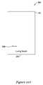
- screen 174may be empty with only a no signal indicator 176 provided on a portion of the display.
- each of the current time 44 , current outdoor temperature 46 and current inside temperature 48may be blank or have dashed lines instead of the appropriate value, especially if current values are not available to the HVAC remote controller 24 via the wireless interface.
- either no signal screen 174 of FIG. 14A or no signal screen 178 of FIG. 14Bmay be provided when the HVAC remote controller 24 is unable to establish communication with the HVAC controller 8 .
- the HVAC remote controller 24may toggle between screens 174 and 178 on the touch screen display 42 .
- the toggle ratemay be 1 second, 2 seconds, 5 seconds, 10 seconds, 30 seconds, 1 minute, or any suitable rate of time, as desired.
- FIGS. 14C and 14Dshow illustrative no signal screens 180 and 188 that may be displayed on the illustrative HVAC remote controller 24 touch screen display 42 when the HVAC remote controller 8 is connected to a zoned HVAC system.
- screen 174may include the current time 44 , the current outdoor temperature 46 , and the current inside temperature 48 .
- each of the current time 44 , current outdoor temperature 46 , and current inside temperature 48may be blank or have dashed lines appearing instead of the appropriate data value.
- a pair of icons 184 and 186may be provided in at least a portion of the touch screen display 42 .
- Icons 184 and 186may be arrows that allow a user to scroll through the available zones of the HVAC system, as discussed previously.
- “NO SIGNAL”may be provided between icons 184 and 186 at region 182 .
- the current zonemay be displayed in region 182 of the touch screen display 42 .
- “BEDROOM 1”may be displayed at region 182 .
- any suitable zone as discussed previouslymay be displayed at region 182 , as desired.
- either no signal screen 180 of FIG. 14C or no signal screen 188 of FIG. 14Dmay be provided when the HVAC remote controller is unable to establish communication with a corresponding zoned HVAC controller 8 .
- the HVAC remote controller 24may toggle between the screens 180 and 188 on the touch screen display 42 .
- the toggle ratemay be one second, two seconds, five seconds, ten seconds, thirty seconds, one minute, or any suitable rate of time, as desired.
- the user touches icons 184 and/or 186 to select a different zone in the HVAC systemand the HVAC remote controller 24 can establish communication with the corresponding HVAC controller 8 , then neither of the no signal screens 180 and 188 may be displayed for the selected zone.
- FIGS. 15A-15Pare pictorial views of illustrative screens that may be displayed on the touch screen display 42 of an illustrative HVAC remote controller 24 .
- FIGS. 15A-15Pmay provide a series of screens, typically accesses sequentially, that help set up the HVAC remote controller 24 .
- the series of screensare at a common menu level rather than a sub-menu. It is contemplated that the illustrative screens may provide an easily navigatable menu including readable words to indicate the menu settings and/or available options as well as the current settings.
- the HVAC remote controller 24may be configured to have a variety of options or settings that can be initially setup by an installer or other user. These options or settings can include, for example, a screen lock feature, a button click feature, a low backlight feature, a temperature offset, a number of zones setting, as well as other features and/or settings.
- an illustrative setup screen 196may be displayed on the touch screen display 42 .
- screen 196may include a message center to display the type of screen that is currently displayed.
- Screen 196provides “SETUP MENU” 200 in the message center.
- Adjacent to the message centeris an icon 210 , having a directional arrow that can be used to navigate to the next screen.
- icon 198which may be a done icon, may be provided so that when the setup is completed, the setup menu may be exited and a home screen may be displayed.
- the touch screen display 42may display screen 202 shown in FIG. 15B .
- screen 202may include “ADD A DEVICE” text 206 in the message center under a “MENU” heading.
- two arrow icons 208 and 210left and right directional arrows, may be provided to allow the user to navigate forward and backward through the sequential menu structure.
- a touch of the touch screen 42 corresponding to icon 210may navigate to the next screen, such as, for example, screen 216 of FIG. 15D , and, a touch of the touch screen 42 corresponding to icon 208 may display the previous screen, or in this case, screen 196 of FIG. 15A .
- icon 204corresponding to a “connect to device” command, may be provided on screen 202 .
- the HVAC remote controller 24may attempt to connect to a device such as an HVAC controller 8 or other device.
- screen 212 of FIG. 15Cmay be displayed on the touch screen display 42 to indicate the attempt.
- screen 212may be a blank screen with only “CONNECTING” 214 provided in the message center.
- next menu screenshown as screen 216 in FIG. 15D
- screen 216may be displayed when icon 210 of screen 202 of FIG. 15B is touched.
- screen 216may include done icon 198 , forward and back navigation icons 208 and 210 , and also “MANUAL LOCK” 222 in the message center.
- manual lockmay activate a screen lock function that requires the user to hold the lock/unlock icons 118 , as described above with respect to FIGS. 9A and 9D , to lock/unlock the screen.
- screen 216may also include an icon 218 for indicating that manual lock is to be set, and an icon 220 for indicating that manual lock is not to be set.
- icon 218may be a yes icon and icon 220 may be a no icon, but these labels are only illustrative.
- the selected iconmay include a bold outline and/or a dot to indicate that it is selected.
- the selected iconmay be designated in any suitable manner.
- icon 220is selected, indicating that the manual lock feature is not enabled.
- icon 218may be touched.
- screen 224 shown in FIG. 15Emay be displayed on the touch screen display 42 .
- Screen 224is the same as screen 216 except that icon 218 includes a bold outline and dot indicating that the manual lock feature is now enabled.
- screen 226 shown in FIG. 15Fmay be displayed.
- screen 226may include done icon 198 , forward and back navigation icons 208 and 210 , and also “AUTOMATIC LOCK” 228 in the message center.
- the automatic lock featuremay automatically lock the HVAC remote controller screen after a period of inactivity by the user, and can be unlocked by, for example, touching icon 118 as described above with respect to FIGS. 9A and 9D . In some cases, there may be a delay before the screen is locked and/or unlocked.
- icon 220includes a bold outline and dot indicating that the automatic locking feature is disabled.
- icon 218includes a bold outline and dot indicating that the automatic locking feature is enabled.
- the featuremay be disabled or enabled by detecting a touch of the touch screen corresponding to icons 218 or 220 , as desired.
- the HVAC remote controller 24may navigate back to screen 216 or 224 , depending on whether the manual lock feature was enabled or disabled. If icon 210 is touched in either screen 226 or 230 , the HVAC remote controller 24 may navigate to the next screen, which in some cases, is screen 232 shown in FIG. 15H . As illustrated in both screens 232 and 236 of FIGS. 15H and 15I , done icon 198 , navigation icons 208 and 210 , yes icon 218 , and no icon 220 may be displayed. In the illustrative screens 232 and 236 , “BUTTON CLICK” 234 may be displayed in the message center.
- the button click featuremay enable or disable a click or other sound to be emitted by the HVAC remote controller 24 when the touch screen is touched and the corresponding input is accepted by the HVAC remote controller 24 . This may help provide feedback to the user that the input has been recognized by the HVAC remote controller 24 .
- icon 218includes a bold outline and dot, which in the illustrative embodiment, indicates that the button click feature is enabled.
- icon 220includes a bold outline and dot, which in the illustrative embodiment, indicates that the button click feature is disabled. This feature may be enabled or disabled by simply touching icon 218 or 220 , respectively.
- screen 238 shown in FIG. 15Jmay be displayed.
- Screen 238allows a user so configure a “LOW BACKLIGHT” feature of the HVAC remote controller 24 .
- “LOW BACKLIGHT” 240may be displayed in the message center.
- icon 220includes a bold outline and dot indicating that the low backlight feature is disabled.
- icon 218includes a bold outline and dot indicating that the low backlight feature is enabled. As discussed previously, this feature may be enabled or disabled by simply touching icons 218 or 220 , respectively.
- screen 244 shown in FIG. 15Lmay be displayed.
- Screen 244allows a user so configure a temperature offset feature of the HVAC remote controller 24 .
- the temperature offset featuremay offset the temperature that is provided on the display 42 relative to the temperature that is sensed by the temperature sensor.
- the label “TEMP OFFSET” 248may be displayed in the message center.
- Screen 244may also include a current temperature offset 246 , which may be adjusted to increase and/or decrease the temperature offset to a desired value.
- screen 254 shown in FIG. 15Mmay be displayed.
- screen 254 of FIG. 15Mmay include a done icon 198 and back and forward navigation icons 208 and 210 .
- the message centermay display a list of zones connected to the HVAC remote controller 24 , such as, for example, “LIVING ROOM” 256 , or any other suitable zone or zones, as discussed previously.
- icons 208 and 210may toggle or navigate through the list of connected zones for the HVAC remote controller 24 . To remove a zone, remove icon 258 may be touched.
- screen 260 of FIG. 15Nmay be displayed on the touch screen display 42 .
- screen 260may include yes icon 218 , no icon 220 , and “ARE YOU SURE” 262 message displayed in the message center.
- screen 260a user may reaffirm the removal of the selected zone by selecting yes icon 218 , or the user may cancel the removal by selecting no icon 220 .
- screen 264 shown in FIG. 15Omay be temporarily displayed.
- screen 264may identify the zone removed in the message center, which, in the illustrative example is “LIVING ROOM” 266 and may further include a remove indicator 268 .
- screen 264may timeout and screen 254 of FIG. 15M may be displayed but with a different zone identified in message center 256 . If the no icon 220 is selected in screen 260 , screen 254 may be displayed.
- screen 250 of FIG. 15Pmay be displayed on the touch screen display 42 .
- Screen 250may display “SAVING CHANGES” 252 in the message center.
- a home screenmay be displayed on the touch screen display 42 .
- FIGS. 15A-15PThe illustrative setup parameters and menus described above with respect to FIGS. 15A-15P are merely illustrative and are not meant to be limiting in any manner. It is contemplated that any suitable HVAC remote controller and/or HVAC controller feature, parameter, and/or setting may be provided in a setup menu, as desired.
- FIGS. 16A-16Dare pictorial views of illustrative screens that may be displayed on the touch screen display 42 of an illustrative HVAC remote controller 24 .
- FIGS. 16A-16Dmay be the initial screens displayed when the HVAC remote controller is to be installed, or when the HVAC remote controller is removed from the box.
- screen 270may be displayed on touch screen display 42 .
- the message centermay provide “ADD A DEVICE” 272 along with icon 274 for initializing an attempt to establishing a connection with a device, such as an HVAC controller 8 .
- icon 274is touched, screen 276 shown in FIG. 16B may be displayed on the touch screen display 42 .
- screen 274may be a blank screen with “CONNECTING” 278 provided in the message center, and in some cases, may blink or otherwise provide an indication that the HVAC remote controller is working. In some cases, though not illustrated, a status bar may be provided if desired.
- screen 280 shown in FIG. 16Cmay be displayed on the touch screen display 42 . If no connection is established, then screen 270 , or, in some cases, the previously described no signal screens may be displayed, if desired.
- screen 280 shown in FIG. 16Cmay be similar to screen 270 with the addition of “DONE” icon 198 .
- a listing of all currently connected devicescan be displayed. From this screen, another device may be added to the HVAC remote controller 24 or the setup may be finished. To add another device, icon 274 may again be touched, similar to that discussed above. To finish setup, the done icon 198 may be touched, and then, screen 282 shown in FIG. 16D may be displayed on the touch screen display 42 . Screen 282 may provide “SAVING CHANGES” 284 in the message center. In the illustrative embodiment, screen 282 may be displayed on the touch screen display 42 for a period of time and then, an appropriate home screen of the HVAC remote controller 24 may be displayed.
Landscapes
- Engineering & Computer Science (AREA)
- Physics & Mathematics (AREA)
- Signal Processing (AREA)
- Chemical & Material Sciences (AREA)
- Combustion & Propulsion (AREA)
- Mechanical Engineering (AREA)
- General Engineering & Computer Science (AREA)
- Fuzzy Systems (AREA)
- Mathematical Physics (AREA)
- General Physics & Mathematics (AREA)
- Automation & Control Theory (AREA)
- Air Conditioning Control Device (AREA)
Abstract
Description
Claims (20)
Priority Applications (2)
| Application Number | Priority Date | Filing Date | Title |
|---|---|---|---|
| US12/323,458US8167216B2 (en) | 2007-11-30 | 2008-11-25 | User setup for an HVAC remote control unit |
| US13/434,783US9765983B2 (en) | 2007-11-30 | 2012-03-29 | User setup for an HVAC remote control unit |
Applications Claiming Priority (2)
| Application Number | Priority Date | Filing Date | Title |
|---|---|---|---|
| US99167407P | 2007-11-30 | 2007-11-30 | |
| US12/323,458US8167216B2 (en) | 2007-11-30 | 2008-11-25 | User setup for an HVAC remote control unit |
Related Child Applications (1)
| Application Number | Title | Priority Date | Filing Date |
|---|---|---|---|
| US13/434,783ContinuationUS9765983B2 (en) | 2007-11-30 | 2012-03-29 | User setup for an HVAC remote control unit |
Publications (2)
| Publication Number | Publication Date |
|---|---|
| US20090140064A1 US20090140064A1 (en) | 2009-06-04 |
| US8167216B2true US8167216B2 (en) | 2012-05-01 |
Family
ID=40674723
Family Applications (5)
| Application Number | Title | Priority Date | Filing Date |
|---|---|---|---|
| US12/323,433Active2033-11-12US9151510B2 (en) | 2007-11-30 | 2008-11-25 | Display for HVAC systems in remote control units |
| US12/323,451Active2030-06-09US8387892B2 (en) | 2007-11-30 | 2008-11-25 | Remote control for use in zoned and non-zoned HVAC systems |
| US12/323,458Active2030-06-01US8167216B2 (en) | 2007-11-30 | 2008-11-25 | User setup for an HVAC remote control unit |
| US12/323,440Active2030-02-17US8224491B2 (en) | 2007-11-30 | 2008-11-25 | Portable wireless remote control unit for use with zoned HVAC system |
| US13/434,783Active2031-05-22US9765983B2 (en) | 2007-11-30 | 2012-03-29 | User setup for an HVAC remote control unit |
Family Applications Before (2)
| Application Number | Title | Priority Date | Filing Date |
|---|---|---|---|
| US12/323,433Active2033-11-12US9151510B2 (en) | 2007-11-30 | 2008-11-25 | Display for HVAC systems in remote control units |
| US12/323,451Active2030-06-09US8387892B2 (en) | 2007-11-30 | 2008-11-25 | Remote control for use in zoned and non-zoned HVAC systems |
Family Applications After (2)
| Application Number | Title | Priority Date | Filing Date |
|---|---|---|---|
| US12/323,440Active2030-02-17US8224491B2 (en) | 2007-11-30 | 2008-11-25 | Portable wireless remote control unit for use with zoned HVAC system |
| US13/434,783Active2031-05-22US9765983B2 (en) | 2007-11-30 | 2012-03-29 | User setup for an HVAC remote control unit |
Country Status (1)
| Country | Link |
|---|---|
| US (5) | US9151510B2 (en) |
Cited By (128)
| Publication number | Priority date | Publication date | Assignee | Title |
|---|---|---|---|---|
| US20100106322A1 (en)* | 2008-10-27 | 2010-04-29 | Lennox Industries Inc. | Communication protocol system and method for a distributed-architecture heating, ventilation and air conditioning network |
| US20120041604A1 (en)* | 2009-03-27 | 2012-02-16 | Alf Isaksson | System For Controlling An Ambient Air Parameter |
| US20120181010A1 (en)* | 2007-11-30 | 2012-07-19 | Honeywell International, Inc. | User setup for an hvac remote control unit |
| US20120232703A1 (en)* | 2011-03-10 | 2012-09-13 | Braeburn Systems, Llc | Rapid programming of thermostat |
| US20120292400A1 (en)* | 2011-05-19 | 2012-11-22 | Jerry Weber | Air control system |
| US20130087628A1 (en)* | 2011-10-07 | 2013-04-11 | Honeywell International Inc. | Thermostat with remote access feature |
| US8433446B2 (en) | 2008-10-27 | 2013-04-30 | Lennox Industries, Inc. | Alarm and diagnostics system and method for a distributed-architecture heating, ventilation and air conditioning network |
| US8437878B2 (en) | 2008-10-27 | 2013-05-07 | Lennox Industries Inc. | Alarm and diagnostics system and method for a distributed architecture heating, ventilation and air conditioning network |
| US8437877B2 (en) | 2008-10-27 | 2013-05-07 | Lennox Industries Inc. | System recovery in a heating, ventilation and air conditioning network |
| US8442693B2 (en) | 2008-10-27 | 2013-05-14 | Lennox Industries, Inc. | System and method of use for a user interface dashboard of a heating, ventilation and air conditioning network |
| US8452456B2 (en) | 2008-10-27 | 2013-05-28 | Lennox Industries Inc. | System and method of use for a user interface dashboard of a heating, ventilation and air conditioning network |
| US8463442B2 (en) | 2008-10-27 | 2013-06-11 | Lennox Industries, Inc. | Alarm and diagnostics system and method for a distributed architecture heating, ventilation and air conditioning network |
| US8463443B2 (en) | 2008-10-27 | 2013-06-11 | Lennox Industries, Inc. | Memory recovery scheme and data structure in a heating, ventilation and air conditioning network |
| US20130219935A1 (en)* | 2012-02-28 | 2013-08-29 | Mitsubishi Electric Corporation | Air-conditioning remote controller and air-conditioning system |
| US8527096B2 (en) | 2008-10-24 | 2013-09-03 | Lennox Industries Inc. | Programmable controller and a user interface for same |
| US8543243B2 (en) | 2008-10-27 | 2013-09-24 | Lennox Industries, Inc. | System and method of use for a user interface dashboard of a heating, ventilation and air conditioning network |
| US8548630B2 (en) | 2008-10-27 | 2013-10-01 | Lennox Industries, Inc. | Alarm and diagnostics system and method for a distributed-architecture heating, ventilation and air conditioning network |
| US8560125B2 (en) | 2008-10-27 | 2013-10-15 | Lennox Industries | Communication protocol system and method for a distributed-architecture heating, ventilation and air conditioning network |
| US8564400B2 (en) | 2008-10-27 | 2013-10-22 | Lennox Industries, Inc. | Communication protocol system and method for a distributed-architecture heating, ventilation and air conditioning network |
| USD693778S1 (en)* | 2012-07-12 | 2013-11-19 | Mitsubishi Electric Corporation | Remote controller for air conditioner |
| US8600558B2 (en) | 2008-10-27 | 2013-12-03 | Lennox Industries Inc. | System recovery in a heating, ventilation and air conditioning network |
| US8600559B2 (en) | 2008-10-27 | 2013-12-03 | Lennox Industries Inc. | Method of controlling equipment in a heating, ventilation and air conditioning network |
| US8615326B2 (en) | 2008-10-27 | 2013-12-24 | Lennox Industries Inc. | System and method of use for a user interface dashboard of a heating, ventilation and air conditioning network |
| US20130345883A1 (en)* | 2010-11-19 | 2013-12-26 | Nest Labs, Inc. | Systems and Methods for a Graphical User Interface of a Controller for an Energy-Consuming System Having Spatially Related Discrete Display Elements |
| US20140031989A1 (en)* | 2012-07-26 | 2014-01-30 | Honeywell International Inc. | Hvac controller with wireless network based occupancy detection and control |
| US8655491B2 (en) | 2008-10-27 | 2014-02-18 | Lennox Industries Inc. | Alarm and diagnostics system and method for a distributed architecture heating, ventilation and air conditioning network |
| US8655490B2 (en) | 2008-10-27 | 2014-02-18 | Lennox Industries, Inc. | System and method of use for a user interface dashboard of a heating, ventilation and air conditioning network |
| US8661165B2 (en) | 2008-10-27 | 2014-02-25 | Lennox Industries, Inc. | Device abstraction system and method for a distributed architecture heating, ventilation and air conditioning system |
| US8694164B2 (en)* | 2008-10-27 | 2014-04-08 | Lennox Industries, Inc. | Interactive user guidance interface for a heating, ventilation and air conditioning system |
| US20140099878A1 (en)* | 2006-04-18 | 2014-04-10 | Gregory S. Daniels | Automatic roof ventilation system |
| US8713697B2 (en) | 2008-07-09 | 2014-04-29 | Lennox Manufacturing, Inc. | Apparatus and method for storing event information for an HVAC system |
| US8725298B2 (en) | 2008-10-27 | 2014-05-13 | Lennox Industries, Inc. | Alarm and diagnostics system and method for a distributed architecture heating, ventilation and conditioning network |
| US8744629B2 (en)* | 2008-10-27 | 2014-06-03 | Lennox Industries Inc. | System and method of use for a user interface dashboard of a heating, ventilation and air conditioning network |
| US8762666B2 (en) | 2008-10-27 | 2014-06-24 | Lennox Industries, Inc. | Backup and restoration of operation control data in a heating, ventilation and air conditioning network |
| US8761945B2 (en) | 2008-10-27 | 2014-06-24 | Lennox Industries Inc. | Device commissioning in a heating, ventilation and air conditioning network |
| US8774210B2 (en) | 2008-10-27 | 2014-07-08 | Lennox Industries, Inc. | Communication protocol system and method for a distributed-architecture heating, ventilation and air conditioning network |
| US8788100B2 (en) | 2008-10-27 | 2014-07-22 | Lennox Industries Inc. | System and method for zoning a distributed-architecture heating, ventilation and air conditioning network |
| US8798796B2 (en) | 2008-10-27 | 2014-08-05 | Lennox Industries Inc. | General control techniques in a heating, ventilation and air conditioning network |
| US8802981B2 (en) | 2008-10-27 | 2014-08-12 | Lennox Industries Inc. | Flush wall mount thermostat and in-set mounting plate for a heating, ventilation and air conditioning system |
| US8855825B2 (en) | 2008-10-27 | 2014-10-07 | Lennox Industries Inc. | Device abstraction system and method for a distributed-architecture heating, ventilation and air conditioning system |
| US8874815B2 (en) | 2008-10-27 | 2014-10-28 | Lennox Industries, Inc. | Communication protocol system and method for a distributed architecture heating, ventilation and air conditioning network |
| US8892223B2 (en) | 2011-09-07 | 2014-11-18 | Honeywell International Inc. | HVAC controller including user interaction log |
| US8892797B2 (en) | 2008-10-27 | 2014-11-18 | Lennox Industries Inc. | Communication protocol system and method for a distributed-architecture heating, ventilation and air conditioning network |
| US8902071B2 (en) | 2011-12-14 | 2014-12-02 | Honeywell International Inc. | HVAC controller with HVAC system fault detection |
| US20150012863A1 (en)* | 2012-12-28 | 2015-01-08 | Panasonic Intellectual Property Corporation Of America | Control method |
| US20150025659A1 (en)* | 2013-07-17 | 2015-01-22 | Google Inc. | Home Automation Network |
| US8977794B2 (en) | 2008-10-27 | 2015-03-10 | Lennox Industries, Inc. | Communication protocol system and method for a distributed-architecture heating, ventilation and air conditioning network |
| US8994539B2 (en) | 2008-10-27 | 2015-03-31 | Lennox Industries, Inc. | Alarm and diagnostics system and method for a distributed-architecture heating, ventilation and air conditioning network |
| US9002523B2 (en) | 2011-12-14 | 2015-04-07 | Honeywell International Inc. | HVAC controller with diagnostic alerts |
| US20150102114A1 (en)* | 2013-10-16 | 2015-04-16 | Harold G. McFarland | Electronic evaporative cooler controller with wireless remote sensor |
| US20150130632A1 (en)* | 2013-11-08 | 2015-05-14 | Ace Dragon Corp. | Data-collecting system and device |
| US20150160691A1 (en)* | 2013-12-06 | 2015-06-11 | ICM Controls Corporation | Controller with dynamically indicated input devices |
| USD743915S1 (en)* | 2012-07-12 | 2015-11-24 | Mitsubishi Electric Corporation | Remote controller for air conditioner |
| US9206993B2 (en) | 2011-12-14 | 2015-12-08 | Honeywell International Inc. | HVAC controller with utility saver switch diagnostic feature |
| US20150369507A1 (en)* | 2014-06-20 | 2015-12-24 | Honeywell International Inc. | Hvac zoning devices, systems, and methods |
| USD748239S1 (en) | 2014-03-06 | 2016-01-26 | Gregory S. Daniels | Roof vent assembly |
| US9268345B2 (en) | 2008-10-27 | 2016-02-23 | Lennox Industries Inc. | System and method of use for a user interface dashboard of a heating, ventilation and air conditioning network |
| US20160069582A1 (en)* | 2014-09-08 | 2016-03-10 | Trane International Inc. | HVAC System with Motion Sensor |
| US9325517B2 (en) | 2008-10-27 | 2016-04-26 | Lennox Industries Inc. | Device abstraction system and method for a distributed-architecture heating, ventilation and air conditioning system |
| USD755944S1 (en) | 2014-03-06 | 2016-05-10 | Gregory S. Daniels | Roof vent assembly |
| US9366448B2 (en) | 2011-06-20 | 2016-06-14 | Honeywell International Inc. | Method and apparatus for configuring a filter change notification of an HVAC controller |
| US9432208B2 (en) | 2008-10-27 | 2016-08-30 | Lennox Industries Inc. | Device abstraction system and method for a distributed architecture heating, ventilation and air conditioning system |
| US9442500B2 (en) | 2012-03-08 | 2016-09-13 | Honeywell International Inc. | Systems and methods for associating wireless devices of an HVAC system |
| USD766193S1 (en)* | 2014-11-07 | 2016-09-13 | Somfy Sas | Wireless remote control |
| US9488994B2 (en) | 2012-03-29 | 2016-11-08 | Honeywell International Inc. | Method and system for configuring wireless sensors in an HVAC system |
| US9584119B2 (en) | 2013-04-23 | 2017-02-28 | Honeywell International Inc. | Triac or bypass circuit and MOSFET power steal combination |
| US9628074B2 (en) | 2014-06-19 | 2017-04-18 | Honeywell International Inc. | Bypass switch for in-line power steal |
| US9632490B2 (en) | 2008-10-27 | 2017-04-25 | Lennox Industries Inc. | System and method for zoning a distributed architecture heating, ventilation and air conditioning network |
| US9651925B2 (en) | 2008-10-27 | 2017-05-16 | Lennox Industries Inc. | System and method for zoning a distributed-architecture heating, ventilation and air conditioning network |
| US9673811B2 (en) | 2013-11-22 | 2017-06-06 | Honeywell International Inc. | Low power consumption AC load switches |
| US9678486B2 (en) | 2008-10-27 | 2017-06-13 | Lennox Industries Inc. | Device abstraction system and method for a distributed-architecture heating, ventilation and air conditioning system |
| US9683749B2 (en) | 2014-07-11 | 2017-06-20 | Honeywell International Inc. | Multiple heatsink cooling system for a line voltage thermostat |
| US9806705B2 (en) | 2013-04-23 | 2017-10-31 | Honeywell International Inc. | Active triac triggering circuit |
| US9857091B2 (en) | 2013-11-22 | 2018-01-02 | Honeywell International Inc. | Thermostat circuitry to control power usage |
| US9890971B2 (en) | 2015-05-04 | 2018-02-13 | Johnson Controls Technology Company | User control device with hinged mounting plate |
| US9965984B2 (en) | 2012-12-05 | 2018-05-08 | Braeburn Systems, Llc | Climate control panel with non-planar display |
| US9983244B2 (en) | 2013-06-28 | 2018-05-29 | Honeywell International Inc. | Power transformation system with characterization |
| US10055323B2 (en) | 2014-10-30 | 2018-08-21 | Braeburn Systems Llc | System and method for monitoring building environmental data |
| US10094585B2 (en) | 2013-01-25 | 2018-10-09 | Honeywell International Inc. | Auto test for delta T diagnostics in an HVAC system |
| US10139843B2 (en) | 2012-02-22 | 2018-11-27 | Honeywell International Inc. | Wireless thermostatic controlled electric heating system |
| US10162327B2 (en) | 2015-10-28 | 2018-12-25 | Johnson Controls Technology Company | Multi-function thermostat with concierge features |
| US10317867B2 (en) | 2016-02-26 | 2019-06-11 | Braeburn Systems Llc | Thermostat update and copy methods and systems |
| US10318266B2 (en) | 2015-11-25 | 2019-06-11 | Johnson Controls Technology Company | Modular multi-function thermostat |
| US10317919B2 (en) | 2016-06-15 | 2019-06-11 | Braeburn Systems Llc | Tamper resistant thermostat having hidden limit adjustment capabilities |
| US10356573B2 (en) | 2014-10-22 | 2019-07-16 | Braeburn Systems Llc | Thermostat synchronization via remote input device |
| US10410300B2 (en) | 2015-09-11 | 2019-09-10 | Johnson Controls Technology Company | Thermostat with occupancy detection based on social media event data |
| US10423142B2 (en) | 2015-02-10 | 2019-09-24 | Braeburn Systems Llc | Thermostat configuration duplication system |
| US10430056B2 (en) | 2014-10-30 | 2019-10-01 | Braeburn Systems Llc | Quick edit system for programming a thermostat |
| US10452084B2 (en) | 2012-03-14 | 2019-10-22 | Ademco Inc. | Operation of building control via remote device |
| US10458669B2 (en) | 2017-03-29 | 2019-10-29 | Johnson Controls Technology Company | Thermostat with interactive installation features |
| US10465930B2 (en) | 2014-03-06 | 2019-11-05 | Gregory S. Daniels | Roof vent with an integrated fan |
| US10488062B2 (en) | 2016-07-22 | 2019-11-26 | Ademco Inc. | Geofence plus schedule for a building controller |
| US10534383B2 (en) | 2011-12-15 | 2020-01-14 | Ademco Inc. | HVAC controller with performance log |
| US10533761B2 (en) | 2011-12-14 | 2020-01-14 | Ademco Inc. | HVAC controller with fault sensitivity |
| US10546472B2 (en) | 2015-10-28 | 2020-01-28 | Johnson Controls Technology Company | Thermostat with direction handoff features |
| US10591877B2 (en) | 2013-12-11 | 2020-03-17 | Ademco Inc. | Building automation remote control device with an in-application tour |
| US10655881B2 (en) | 2015-10-28 | 2020-05-19 | Johnson Controls Technology Company | Thermostat with halo light system and emergency directions |
| US10677484B2 (en) | 2015-05-04 | 2020-06-09 | Johnson Controls Technology Company | User control device and multi-function home control system |
| US10712038B2 (en) | 2017-04-14 | 2020-07-14 | Johnson Controls Technology Company | Multi-function thermostat with air quality display |
| USD891604S1 (en) | 2015-11-19 | 2020-07-28 | Gregory S. Daniels | Roof vent assembly |
| US10747243B2 (en) | 2011-12-14 | 2020-08-18 | Ademco Inc. | HVAC controller with HVAC system failure detection |
| US10761704B2 (en) | 2014-06-16 | 2020-09-01 | Braeburn Systems Llc | Graphical highlight for programming a control |
| US10760809B2 (en) | 2015-09-11 | 2020-09-01 | Johnson Controls Technology Company | Thermostat with mode settings for multiple zones |
| US10802513B1 (en) | 2019-05-09 | 2020-10-13 | Braeburn Systems Llc | Comfort control system with hierarchical switching mechanisms |
| US10811892B2 (en) | 2013-06-28 | 2020-10-20 | Ademco Inc. | Source management for a power transformation system |
| US10921008B1 (en) | 2018-06-11 | 2021-02-16 | Braeburn Systems Llc | Indoor comfort control system and method with multi-party access |
| US10928087B2 (en) | 2012-07-26 | 2021-02-23 | Ademco Inc. | Method of associating an HVAC controller with an external web service |
| US10941951B2 (en) | 2016-07-27 | 2021-03-09 | Johnson Controls Technology Company | Systems and methods for temperature and humidity control |
| US11054448B2 (en) | 2013-06-28 | 2021-07-06 | Ademco Inc. | Power transformation self characterization mode |
| US11107390B2 (en) | 2018-12-21 | 2021-08-31 | Johnson Controls Technology Company | Display device with halo |
| USD930810S1 (en) | 2015-11-19 | 2021-09-14 | Gregory S. Daniels | Roof vent |
| US11131474B2 (en) | 2018-03-09 | 2021-09-28 | Johnson Controls Tyco IP Holdings LLP | Thermostat with user interface features |
| US11162698B2 (en) | 2017-04-14 | 2021-11-02 | Johnson Controls Tyco IP Holdings LLP | Thermostat with exhaust fan control for air quality and humidity control |
| US11216020B2 (en) | 2015-05-04 | 2022-01-04 | Johnson Controls Tyco IP Holdings LLP | Mountable touch thermostat using transparent screen technology |
| US11269364B2 (en) | 2016-09-19 | 2022-03-08 | Braeburn Systems Llc | Control management system having perpetual calendar with exceptions |
| US11277893B2 (en) | 2015-10-28 | 2022-03-15 | Johnson Controls Technology Company | Thermostat with area light system and occupancy sensor |
| US11326793B2 (en) | 2018-12-21 | 2022-05-10 | Gregory S. Daniels | Roof vent and roof ventilation system |
| USD953372S1 (en) | 2020-06-15 | 2022-05-31 | Honeywell International Inc. | Building controller touchscreen with control icon |
| USD957411S1 (en) | 2020-06-15 | 2022-07-12 | Honeywell International Inc. | Display screen with icon for a building controller lock screen |
| USD963834S1 (en) | 2020-10-27 | 2022-09-13 | Gregory S. Daniels | Roof vent with a circular integrated fan |
| USD964546S1 (en) | 2020-10-27 | 2022-09-20 | Gregory S. Daniels | Roof vent with a circular integrated fan |
| US11499736B2 (en) | 2018-02-09 | 2022-11-15 | Carrier Corporation | HVAC equipment settings |
| USD977343S1 (en) | 2021-03-09 | 2023-02-07 | Research Products Corporation | Heating ventilation and air conditioning controller |
| USD977996S1 (en) | 2020-12-18 | 2023-02-14 | Research Products Corporation | Heating ventilation and air conditioning controller |
| USD979596S1 (en)* | 2021-04-15 | 2023-02-28 | Koninklijke Philips N.V. | Display screen or portion thereof with animated graphical user interface |
| US11925260B1 (en) | 2021-10-19 | 2024-03-12 | Braeburn Systems Llc | Thermostat housing assembly and methods |
| USD1086158S1 (en)* | 2021-02-03 | 2025-07-29 | Belimo Holding Ag | Display panel with a graphical user interface |
| USD1092500S1 (en) | 2023-05-17 | 2025-09-09 | Honeywell International Inc. | Building controller display screen or portion thereof with graphical user interface |
Families Citing this family (210)
| Publication number | Priority date | Publication date | Assignee | Title |
|---|---|---|---|---|
| US7222494B2 (en) | 2004-01-07 | 2007-05-29 | Honeywell International Inc. | Adaptive intelligent circulation control methods and systems |
| US8033479B2 (en) | 2004-10-06 | 2011-10-11 | Lawrence Kates | Electronically-controlled register vent for zone heating and cooling |
| US7784704B2 (en) | 2007-02-09 | 2010-08-31 | Harter Robert J | Self-programmable thermostat |
| GB2447672B (en) | 2007-03-21 | 2011-12-14 | Ford Global Tech Llc | Vehicle manoeuvring aids |
| US8374725B1 (en)* | 2007-11-27 | 2013-02-12 | Joseph David Ols | Climate control |
| US20090276096A1 (en)* | 2008-05-02 | 2009-11-05 | Carrier Corporation | Device and method for controlling a display using a virtual display buffer |
| US9515538B2 (en)* | 2008-05-29 | 2016-12-06 | Nidec Motor Corporation | Dynamoelectric machine assemblies having memory for use by external devices |
| JP5233470B2 (en)* | 2008-07-23 | 2013-07-10 | ダイキン工業株式会社 | Group management device and group management system |
| US9261888B2 (en)* | 2008-10-27 | 2016-02-16 | Lennox Industries Inc. | System and method of use for a user interface dashboard of a heating, ventilation and air conditioning network |
| US20110140914A1 (en)* | 2008-11-24 | 2011-06-16 | Midori Technologies Ltd. | Controller system |
| US8497796B2 (en)* | 2009-01-23 | 2013-07-30 | Alcatel Lucent | Methods and apparatus for controlling one or more electronic devices based on the location of a user |
| US20100207802A1 (en)* | 2009-02-17 | 2010-08-19 | Yung-Hung Chih | G-sensor remote controller |
| JP2010190521A (en)* | 2009-02-19 | 2010-09-02 | Sanyo Electric Co Ltd | Centralized monitoring apparatus |
| KR101537706B1 (en)* | 2009-04-16 | 2015-07-20 | 엘지전자 주식회사 | Mobile terminal and control method thereof |
| KR20110001559U (en)* | 2009-08-07 | 2011-02-15 | (주)에스티오 | Heating apparatus for a mattress |
| EP2325712A1 (en)* | 2009-11-20 | 2011-05-25 | Zerogroup Holding OÜ | Control panel for a control system and a control system |
| KR101642725B1 (en)* | 2010-04-14 | 2016-08-11 | 삼성전자 주식회사 | Method and apparatus for managing lock function in mobile terminal |
| US20110253694A1 (en)* | 2010-04-16 | 2011-10-20 | Nunzio Consiglio | Radiant Heating Tile System |
| JP2011248768A (en)* | 2010-05-28 | 2011-12-08 | Sony Corp | Information processor, information processing system and program |
| US9002481B2 (en) | 2010-07-14 | 2015-04-07 | Honeywell International Inc. | Building controllers with local and global parameters |
| US9182138B2 (en)* | 2010-07-16 | 2015-11-10 | Air Vent, Inc. | Method and apparatus for attic fan power controller with remote control |
| US9667070B2 (en)* | 2010-07-16 | 2017-05-30 | Lg Electronics Inc. | Network system |
| US8918219B2 (en) | 2010-11-19 | 2014-12-23 | Google Inc. | User friendly interface for control unit |
| US8727611B2 (en) | 2010-11-19 | 2014-05-20 | Nest Labs, Inc. | System and method for integrating sensors in thermostats |
| US8510255B2 (en) | 2010-09-14 | 2013-08-13 | Nest Labs, Inc. | Occupancy pattern detection, estimation and prediction |
| US9104211B2 (en) | 2010-11-19 | 2015-08-11 | Google Inc. | Temperature controller with model-based time to target calculation and display |
| US9489062B2 (en)* | 2010-09-14 | 2016-11-08 | Google Inc. | User interfaces for remote management and control of network-connected thermostats |
| US8843239B2 (en) | 2010-11-19 | 2014-09-23 | Nest Labs, Inc. | Methods, systems, and related architectures for managing network connected thermostats |
| US9098279B2 (en)* | 2010-09-14 | 2015-08-04 | Google Inc. | Methods and systems for data interchange between a network-connected thermostat and cloud-based management server |
| US10048705B2 (en)* | 2010-09-21 | 2018-08-14 | Honeywell International Inc. | HVAC schedule with designated off periods |
| US8950687B2 (en) | 2010-09-21 | 2015-02-10 | Honeywell International Inc. | Remote control of an HVAC system that uses a common temperature setpoint for both heat and cool modes |
| US8719720B2 (en) | 2010-09-24 | 2014-05-06 | Honeywell International Inc. | Economizer controller plug and play system recognition with automatic user interface population |
| US10163273B2 (en) | 2010-09-28 | 2018-12-25 | Ford Global Technologies, Llc | Method and system for operating mobile applications in a vehicle |
| US20120124500A1 (en)* | 2010-11-16 | 2012-05-17 | Motorola Mobility, Inc. | Use of discrete input to control controllable device |
| US11334034B2 (en) | 2010-11-19 | 2022-05-17 | Google Llc | Energy efficiency promoting schedule learning algorithms for intelligent thermostat |
| US8850348B2 (en) | 2010-12-31 | 2014-09-30 | Google Inc. | Dynamic device-associated feedback indicative of responsible device usage |
| US9046898B2 (en) | 2011-02-24 | 2015-06-02 | Google Inc. | Power-preserving communications architecture with long-polling persistent cloud channel for wireless network-connected thermostat |
| US9256230B2 (en) | 2010-11-19 | 2016-02-09 | Google Inc. | HVAC schedule establishment in an intelligent, network-connected thermostat |
| US9448567B2 (en) | 2010-11-19 | 2016-09-20 | Google Inc. | Power management in single circuit HVAC systems and in multiple circuit HVAC systems |
| US10346275B2 (en) | 2010-11-19 | 2019-07-09 | Google Llc | Attributing causation for energy usage and setpoint changes with a network-connected thermostat |
| US8195313B1 (en) | 2010-11-19 | 2012-06-05 | Nest Labs, Inc. | Thermostat user interface |
| US9268344B2 (en) | 2010-11-19 | 2016-02-23 | Google Inc. | Installation of thermostat powered by rechargeable battery |
| US9552002B2 (en) | 2010-11-19 | 2017-01-24 | Google Inc. | Graphical user interface for setpoint creation and modification |
| US9003816B2 (en) | 2010-11-19 | 2015-04-14 | Google Inc. | HVAC controller with user-friendly installation features facilitating both do-it-yourself and professional installation scenarios |
| US9459018B2 (en) | 2010-11-19 | 2016-10-04 | Google Inc. | Systems and methods for energy-efficient control of an energy-consuming system |
| US10241527B2 (en) | 2010-11-19 | 2019-03-26 | Google Llc | Thermostat graphical user interface |
| US9092039B2 (en) | 2010-11-19 | 2015-07-28 | Google Inc. | HVAC controller with user-friendly installation features with wire insertion detection |
| US9453655B2 (en) | 2011-10-07 | 2016-09-27 | Google Inc. | Methods and graphical user interfaces for reporting performance information for an HVAC system controlled by a self-programming network-connected thermostat |
| US8788103B2 (en) | 2011-02-24 | 2014-07-22 | Nest Labs, Inc. | Power management in energy buffered building control unit |
| JP5679782B2 (en)* | 2010-11-26 | 2015-03-04 | 京セラ株式会社 | Portable electronic device, screen control method, and screen control program |
| US9558015B2 (en) | 2010-11-29 | 2017-01-31 | Ford Global Technologies, Llc | Methods and apparatus for activating applications |
| CN107065961B (en) | 2010-12-31 | 2020-06-16 | 谷歌有限责任公司 | Flexible functional partitioning of intelligent thermostat controlled HVAC systems |
| US8690074B2 (en)* | 2010-12-31 | 2014-04-08 | Braeburn Systems Llc | Switch for multi function control of a thermostat |
| WO2012092622A2 (en) | 2010-12-31 | 2012-07-05 | Nest Labs, Inc. | Inhibiting deleterious control coupling in an enclosure having multiple hvac regions |
| US8990689B2 (en) | 2011-02-03 | 2015-03-24 | Sony Corporation | Training for substituting touch gestures for GUI or hardware keys to control audio video play |
| US9047005B2 (en)* | 2011-02-03 | 2015-06-02 | Sony Corporation | Substituting touch gestures for GUI or hardware keys to control audio video play |
| WO2012112415A1 (en)* | 2011-02-14 | 2012-08-23 | Carrier Corporation | System and method for establishing activity based environmental control |
| US8511577B2 (en) | 2011-02-24 | 2013-08-20 | Nest Labs, Inc. | Thermostat with power stealing delay interval at transitions between power stealing states |
| US8944338B2 (en) | 2011-02-24 | 2015-02-03 | Google Inc. | Thermostat with self-configuring connections to facilitate do-it-yourself installation |
| US8494681B2 (en)* | 2011-03-28 | 2013-07-23 | Emerson Electric Co. | Controller for a climate control system |
| US8774947B2 (en) | 2011-03-28 | 2014-07-08 | Emerson Electric Co. | Controller for a climate control system |
| US9290204B2 (en) | 2011-04-19 | 2016-03-22 | Ford Global Technologies, Llc | Hitch angle monitoring system and method |
| US9854209B2 (en) | 2011-04-19 | 2017-12-26 | Ford Global Technologies, Llc | Display system utilizing vehicle and trailer dynamics |
| US9374562B2 (en) | 2011-04-19 | 2016-06-21 | Ford Global Technologies, Llc | System and method for calculating a horizontal camera to target distance |
| US9506774B2 (en) | 2011-04-19 | 2016-11-29 | Ford Global Technologies, Llc | Method of inputting a path for a vehicle and trailer |
| US9500497B2 (en) | 2011-04-19 | 2016-11-22 | Ford Global Technologies, Llc | System and method of inputting an intended backing path |
| US9969428B2 (en) | 2011-04-19 | 2018-05-15 | Ford Global Technologies, Llc | Trailer backup assist system with waypoint selection |
| US9926008B2 (en) | 2011-04-19 | 2018-03-27 | Ford Global Technologies, Llc | Trailer backup assist system with waypoint selection |
| US9555832B2 (en) | 2011-04-19 | 2017-01-31 | Ford Global Technologies, Llc | Display system utilizing vehicle and trailer dynamics |
| US9115908B2 (en) | 2011-07-27 | 2015-08-25 | Honeywell International Inc. | Systems and methods for managing a programmable thermostat |
| US8694203B2 (en)* | 2011-09-12 | 2014-04-08 | Ford Global Technologies, Llc | Method and apparatus for vehicle process emulation and configuration on a mobile platform |
| US9222693B2 (en) | 2013-04-26 | 2015-12-29 | Google Inc. | Touchscreen device user interface for remote control of a thermostat |
| US8893032B2 (en) | 2012-03-29 | 2014-11-18 | Google Inc. | User interfaces for HVAC schedule display and modification on smartphone or other space-limited touchscreen device |
| CA3044757C (en) | 2011-10-21 | 2021-11-09 | Google Llc | User-friendly, network connected learning thermostat and related systems and methods |
| CN106440187A (en) | 2011-10-21 | 2017-02-22 | 谷歌公司 | Energy efficiency promoting schedule learning algorithms for intelligent thermostat |
| JP6121431B2 (en) | 2011-10-21 | 2017-04-26 | グーグル インコーポレイテッド | Automatic control schedule acquisition in the intelligent controller |
| JP5333565B2 (en)* | 2011-11-16 | 2013-11-06 | 株式会社富士通ゼネラル | Air conditioner |
| US20130147812A1 (en)* | 2011-12-13 | 2013-06-13 | Lennox Industries Inc. | Heating, ventilation and air conditioning system user interface having proportional animation graphics and method of operation thereof |
| US8878854B2 (en)* | 2011-12-13 | 2014-11-04 | Lennox Industries Inc. | Heating, ventilation and air conditioning system user interface having adjustable fonts and method of operation thereof |
| US20130345882A1 (en)* | 2011-12-22 | 2013-12-26 | Steven David Dushane | Programmable environmental comfort controller |
| US20130197698A1 (en)* | 2012-01-26 | 2013-08-01 | Carrier Corporation | HVAC System Fault Root Cause Self-Determination |
| JP5633526B2 (en)* | 2012-01-30 | 2014-12-03 | コニカミノルタ株式会社 | Information processing apparatus, information processing apparatus control method, and information processing apparatus control program |
| US9810441B2 (en) | 2012-02-23 | 2017-11-07 | Honeywell International Inc. | HVAC controller with indoor air quality scheduling |
| US9643471B2 (en)* | 2012-03-27 | 2017-05-09 | Ford Global Technologies, Llc | Driver personalized climate conditioning |
| CN106288191B (en) | 2012-03-29 | 2020-08-25 | 谷歌有限责任公司 | Processing and reporting usage information for a network-connected thermostat-controlled HVAC system |
| US9098096B2 (en) | 2012-04-05 | 2015-08-04 | Google Inc. | Continuous intelligent-control-system update using information requests directed to user devices |
| US10054964B2 (en) | 2012-05-07 | 2018-08-21 | Google Llc | Building control unit method and controls |
| US9078088B2 (en) | 2012-07-12 | 2015-07-07 | Myine Electronics, Inc. | System and method for transport layer agnostic programming interface for use with smartphones |
| KR102043194B1 (en)* | 2012-07-25 | 2019-11-11 | 엘지전자 주식회사 | Air-conditioner management system and method for controlling air-conditioner |
| US9410752B2 (en)* | 2012-08-17 | 2016-08-09 | Albert Reid Wallace | Hydronic building systems control |
| US9208676B2 (en) | 2013-03-14 | 2015-12-08 | Google Inc. | Devices, methods, and associated information processing for security in a smart-sensored home |
| US8708242B2 (en) | 2012-09-21 | 2014-04-29 | Nest Labs, Inc. | Thermostat system with software-repurposable wiring terminals adaptable for HVAC systems of different ranges of complexity |
| US9520252B2 (en) | 2012-09-21 | 2016-12-13 | Google Inc. | Adaptable hazard detector mounting plate |
| US9007222B2 (en) | 2012-09-21 | 2015-04-14 | Google Inc. | Detector unit and sensing chamber therefor |
| US8659302B1 (en) | 2012-09-21 | 2014-02-25 | Nest Labs, Inc. | Monitoring and recoverable protection of thermostat switching circuitry |
| US9046414B2 (en) | 2012-09-21 | 2015-06-02 | Google Inc. | Selectable lens button for a hazard detector and method therefor |
| US8994540B2 (en) | 2012-09-21 | 2015-03-31 | Google Inc. | Cover plate for a hazard detector having improved air flow and other characteristics |
| US8594850B1 (en) | 2012-09-30 | 2013-11-26 | Nest Labs, Inc. | Updating control software on a network-connected HVAC controller |
| WO2014051634A1 (en)* | 2012-09-30 | 2014-04-03 | Nest Labs, Inc. | Intelligent controller for an environmental control system |
| US8554376B1 (en) | 2012-09-30 | 2013-10-08 | Nest Labs, Inc | Intelligent controller for an environmental control system |
| US20140156087A1 (en)* | 2012-11-30 | 2014-06-05 | Honeywell International Inc. | Hvac controller that facilitates installer setup via a remote user interface |
| US9508251B1 (en)* | 2012-11-30 | 2016-11-29 | Hkc-Us, Llc | Seasonal switch for remote controls |
| WO2014103307A1 (en)* | 2012-12-28 | 2014-07-03 | パナソニック株式会社 | Control method |
| US9218805B2 (en) | 2013-01-18 | 2015-12-22 | Ford Global Technologies, Llc | Method and apparatus for incoming audio processing |
| US20140207291A1 (en)* | 2013-01-21 | 2014-07-24 | Lennox Industries Inc. | User interface screens for zoned hvac systems, a controller employing the screens and a method of operating a zoned hvac system |
| US8981916B2 (en) | 2013-01-28 | 2015-03-17 | Ford Global Technologies, Llc | Method and apparatus for customized vehicle sound-based location |
| US9592851B2 (en) | 2013-02-04 | 2017-03-14 | Ford Global Technologies, Llc | Control modes for a trailer backup assist system |
| US9511799B2 (en) | 2013-02-04 | 2016-12-06 | Ford Global Technologies, Llc | Object avoidance for a trailer backup assist system |
| US9042603B2 (en) | 2013-02-25 | 2015-05-26 | Ford Global Technologies, Llc | Method and apparatus for estimating the distance from trailer axle to tongue |
| US10001790B2 (en)* | 2013-02-26 | 2018-06-19 | Honeywell International Inc. | Security system with integrated HVAC control |
| US20140250399A1 (en)* | 2013-03-04 | 2014-09-04 | Emerson Electric Co. | Scheduling Systems |
| US9274684B2 (en)* | 2013-03-07 | 2016-03-01 | Siemens Industry, Inc. | Hierarchical navigation with related objects |
| US9551501B2 (en)* | 2013-03-15 | 2017-01-24 | Honeywell International Inc. | Multi-mode auto changeover system |
| US9479601B2 (en) | 2013-03-15 | 2016-10-25 | Ford Global Technologies, Llc | Method and apparatus for seamless application portability over multiple environments |
| US8933822B2 (en) | 2013-03-15 | 2015-01-13 | Ford Global Technologies, Llc | Method and apparatus for extra-vehicular emergency updates following an accident |
| US10852025B2 (en) | 2013-04-30 | 2020-12-01 | Ademco Inc. | HVAC controller with fixed segment display having fixed segment icons and animation |
| US9197336B2 (en) | 2013-05-08 | 2015-11-24 | Myine Electronics, Inc. | System and method for providing customized audio content to a vehicle radio system using a smartphone |
| WO2014182623A1 (en)* | 2013-05-09 | 2014-11-13 | Siemens Industry, Inc. | Interface for adjustment of portions of a building automation system |
| USD703156S1 (en)* | 2013-06-13 | 2014-04-22 | Rheem Manufacturing Company | Electronic control device |
| USD703157S1 (en)* | 2013-06-13 | 2014-04-22 | Rheem Manufacturing Company | Control panel |
| USD703158S1 (en)* | 2013-06-13 | 2014-04-22 | Rheem Manufacturing Company | Electronic control enclosure |
| JP6037980B2 (en)* | 2013-09-04 | 2016-12-07 | 三菱電機株式会社 | Air conditioner |
| EP3042138A4 (en) | 2013-09-04 | 2016-08-17 | Cellier Domesticus Inc | METHOD AND SYSTEM FOR CONTROLLING AN ARTIFICIAL CELL |
| US20150116507A1 (en)* | 2013-10-25 | 2015-04-30 | Ciil Technologies, Llc | Monitoring system for an outdoor display |
| US9352777B2 (en) | 2013-10-31 | 2016-05-31 | Ford Global Technologies, Llc | Methods and systems for configuring of a trailer maneuvering system |
| JP2015097356A (en)* | 2013-11-15 | 2015-05-21 | キヤノン株式会社 | Communication system, image forming apparatus, control method therefor, and program |
| CN105706395B (en)* | 2014-01-06 | 2020-01-14 | 三星电子株式会社 | Control apparatus and control method thereof |
| US9233710B2 (en) | 2014-03-06 | 2016-01-12 | Ford Global Technologies, Llc | Trailer backup assist system using gesture commands and method |
| JP2015169386A (en)* | 2014-03-07 | 2015-09-28 | 三菱電機株式会社 | Air conditioner |
| US9568201B2 (en) | 2014-03-28 | 2017-02-14 | Google Inc. | Environmental control system retrofittable with multiple types of boiler-based heating systems |
| US9609462B2 (en) | 2014-03-28 | 2017-03-28 | Google Inc. | Facilitating radio frequency communications among environmental control system components |
| US9581342B2 (en) | 2014-03-28 | 2017-02-28 | Google Inc. | Mounting stand for multi-sensing environmental control device |
| US9791839B2 (en) | 2014-03-28 | 2017-10-17 | Google Inc. | User-relocatable self-learning environmental control device capable of adapting previous learnings to current location in controlled environment |
| JP1524665S (en)* | 2014-07-14 | 2015-06-01 | ||
| JP1544559S (en)* | 2014-07-14 | 2016-02-29 | ||
| JP1524664S (en)* | 2014-07-14 | 2015-06-01 | ||
| US9874366B2 (en) | 2014-07-30 | 2018-01-23 | Research Products Corporation | System and method for adjusting fractional on-time and cycle time to compensate for weather extremes and meet ventilation requirements |
| AU361251S (en)* | 2014-11-11 | 2015-04-16 | Daikin Ind Ltd | Remote controller for air conditioner |
| JP1533098S (en)* | 2014-11-11 | 2015-09-07 | ||
| AU361249S (en)* | 2014-11-11 | 2015-04-16 | Daikin Ind Ltd | Remote controller for air conditioner |
| AU361248S (en)* | 2014-11-11 | 2015-04-16 | Daikin Ind Ltd | Remote controller for air conditioner |
| AU361250S (en)* | 2014-11-11 | 2015-04-16 | Daikin Ind Ltd | Remote controller for air conditioner |
| JP1542056S (en)* | 2014-11-11 | 2016-01-25 | ||
| JP1542055S (en)* | 2014-11-11 | 2016-01-25 | ||
| CN104407592B (en)* | 2014-11-27 | 2018-11-23 | 小米科技有限责任公司 | A kind of method and device adjusting smart home device operating status |
| US9565287B2 (en)* | 2014-11-28 | 2017-02-07 | Panasonic Intellectual Property Corporation Of America | Remote control method and remote control system |
| US9522677B2 (en) | 2014-12-05 | 2016-12-20 | Ford Global Technologies, Llc | Mitigation of input device failure and mode management |
| US9533683B2 (en) | 2014-12-05 | 2017-01-03 | Ford Global Technologies, Llc | Sensor failure mitigation system and mode management |
| US9612031B2 (en) | 2015-01-07 | 2017-04-04 | Google Inc. | Thermostat switching circuitry robust against anomalous HVAC control line conditions |
| US10302329B2 (en) | 2015-01-19 | 2019-05-28 | Lennox Industries, Inc. | Device for operating a heating, ventilation, and air conditioning network |
| USD801288S1 (en)* | 2015-01-29 | 2017-10-31 | Samsung Electronics Co., Ltd. | Remote control for air conditioner |
| USD786803S1 (en)* | 2015-01-29 | 2017-05-16 | Samsung Electronics Co., Ltd. | Remote control for air conditioner |
| US9396633B1 (en) | 2015-06-14 | 2016-07-19 | Google Inc. | Systems, methods, and devices for managing coexistence of multiple transceiver devices by optimizing component layout |
| US9679454B2 (en) | 2015-02-06 | 2017-06-13 | Google Inc. | Systems, methods, and devices for managing coexistence of multiple transceiver devices using control signals |
| US9794522B2 (en) | 2015-02-06 | 2017-10-17 | Google Inc. | Systems, methods, and devices for managing coexistence of multiple transceiver devices by optimizing component layout |
| DE102015103521A1 (en)* | 2015-03-10 | 2016-09-15 | Zehnder Group International Ag | Control arrangement for temperature control devices and control methods |
| JP1543609S (en)* | 2015-06-09 | 2016-02-15 | ||
| JP1543972S (en)* | 2015-06-09 | 2016-02-15 | ||
| US9543998B2 (en) | 2015-06-14 | 2017-01-10 | Google Inc. | Systems, methods, and devices for managing coexistence of multiple transceiver devices using bypass circuitry |
| CN105091221A (en)* | 2015-07-31 | 2015-11-25 | 广东美的制冷设备有限公司 | Air conditioner control system, air conditioner and air conditioner control method |
| CN104990233A (en)* | 2015-07-31 | 2015-10-21 | 广东美的制冷设备有限公司 | Air conditioner control system, air conditioner and air conditioner control method |
| US20170059187A1 (en)* | 2015-08-26 | 2017-03-02 | Clyde Wesley Smith, JR. | Solar Energy Attic Air Heat Reservoir System |
| US9896130B2 (en) | 2015-09-11 | 2018-02-20 | Ford Global Technologies, Llc | Guidance system for a vehicle reversing a trailer along an intended backing path |
| US9702582B2 (en) | 2015-10-12 | 2017-07-11 | Ikorongo Technology, LLC | Connected thermostat for controlling a climate system based on a desired usage profile in comparison to other connected thermostats controlling other climate systems |
| US10353360B2 (en) | 2015-10-19 | 2019-07-16 | Ademco Inc. | Method of smart scene management using big data pattern analysis |
| US11029807B2 (en)* | 2015-10-22 | 2021-06-08 | Carrier Corporation | Thermostat with an interactive twisted nematic display |
| USD795712S1 (en) | 2015-11-17 | 2017-08-29 | Dometic Sweden Ab | Thermostat |
| US10895395B2 (en) | 2016-01-29 | 2021-01-19 | Mitsubishi Electric Corporation | Air-conditioner remote controller and air-conditioning control system |
| WO2017139841A1 (en)* | 2016-02-15 | 2017-08-24 | Rooyenburg Pty Ltd | Air conditioning control system |
| DE202016101134U1 (en)* | 2016-03-02 | 2017-06-06 | Thomas Haug | Protective / Operation Record |
| US10112646B2 (en) | 2016-05-05 | 2018-10-30 | Ford Global Technologies, Llc | Turn recovery human machine interface for trailer backup assist |
| US10613213B2 (en) | 2016-05-13 | 2020-04-07 | Google Llc | Systems, methods, and devices for utilizing radar with smart devices |
| US10687184B2 (en) | 2016-05-13 | 2020-06-16 | Google Llc | Systems, methods, and devices for utilizing radar-based touch interfaces |
| US9857810B2 (en)* | 2016-05-18 | 2018-01-02 | Clyde Wesley Smith, JR. | Solar energy space heating thermostatic controller |
| US10528020B2 (en) | 2016-08-09 | 2020-01-07 | Johnson Controls Technology Company | Building control system with adaptive user interface |
| KR20180067874A (en)* | 2016-12-13 | 2018-06-21 | 엘지전자 주식회사 | Bathroom management system |
| CN107355944A (en)* | 2017-06-21 | 2017-11-17 | 珠海格力电器股份有限公司 | Control method and device of air conditioner |
| US10619877B2 (en)* | 2017-06-26 | 2020-04-14 | Therma-Stor LLC | Control panel for a portable dehumidifier |
| USD941804S1 (en)* | 2017-09-04 | 2022-01-25 | Daikin Industries, Ltd. | Remote controller with display |
| EP3712528B1 (en)* | 2017-11-14 | 2022-09-28 | Mitsubishi Electric Corporation | Control system, installation equipment, remote controller, control method, and program |
| US20210276266A1 (en)* | 2018-01-29 | 2021-09-09 | Hewlett-Packard Development Company, L.P. | Additive manufacturing temperature control |
| US10955162B2 (en) | 2018-03-07 | 2021-03-23 | Johnson Controls Technology Company | Portable thermostat systems and methods |
| US10691423B2 (en) | 2018-04-04 | 2020-06-23 | Johnson Controls Technology Company | Testing systems and methods for performing HVAC zone airflow adjustments |
| US10992175B2 (en) | 2018-06-15 | 2021-04-27 | Google Llc | Communication circuit for 2-wire protocols between HVAC systems and smart-home devices |
| JP7039510B2 (en)* | 2018-09-03 | 2022-03-22 | 株式会社東芝 | Terminal equipment, programs and air conditioning systems |
| US11274848B2 (en)* | 2018-09-03 | 2022-03-15 | Kabushiki Kaisha Toshiba | Terminal device, storage medium and air conditioning system |
| US20210285677A1 (en)* | 2018-09-28 | 2021-09-16 | Mitsubishi Electric Corporation | Air-conditioning system and application program |
| US10907854B2 (en) | 2018-10-10 | 2021-02-02 | Ademco Inc. | Automatic changeover mode in an HVAC controller with reversible deadband enforcement |
| US11236923B2 (en) | 2018-10-10 | 2022-02-01 | Ademco Inc. | Thermostat with sensor priority screen |
| US11067307B2 (en) | 2018-10-10 | 2021-07-20 | Ademco Inc. | Thermostat user interface with smart menu structure |
| US10908001B2 (en) | 2018-10-10 | 2021-02-02 | Ademco Inc. | Wireless sensor with mounting plate |
| US10816230B2 (en) | 2018-10-10 | 2020-10-27 | Ademco Inc. | Temperature sensing strategy with multiple temperature sensors |
| US10859281B2 (en) | 2018-10-10 | 2020-12-08 | Ademco Inc. | Thermostat assembly with removable trim ring |
| US10895397B2 (en) | 2018-10-10 | 2021-01-19 | Ademco Inc. | Wire detection for an HVAC controller |
| US10907852B2 (en) | 2018-10-10 | 2021-02-02 | Ademco Inc. | Remote sensor with improved occupancy sensing |
| US11095469B2 (en) | 2018-10-10 | 2021-08-17 | Ademco Inc. | Wireless occupancy sensor with controllable light indicator |
| US10900687B2 (en) | 2018-10-31 | 2021-01-26 | Trane International Inc. | Flexible scheduling HVAC graphical user interface and methods of use thereof |
| US11175057B2 (en)* | 2018-11-27 | 2021-11-16 | Johnson Controls Technology Company | HVAC multi-zone management screen systems and methods |
| US11112139B2 (en) | 2018-12-03 | 2021-09-07 | Ademco Inc. | HVAC controller with a zone commissioning mode |
| US20200225812A1 (en) | 2019-01-11 | 2020-07-16 | Honeywell International Inc. | User interface module for a building control system |
| US11199338B2 (en)* | 2019-05-24 | 2021-12-14 | Ademco Inc. | Selecting a fallback temperature sensor for no occupancy |
| US10798462B1 (en)* | 2019-08-21 | 2020-10-06 | Rcs Technology, Llc | HVAC-based volume control |
| JP7258701B2 (en)* | 2019-09-17 | 2023-04-17 | 株式会社東芝 | Control device, terminal device and method |
| USD933081S1 (en)* | 2019-10-11 | 2021-10-12 | Igt | Gaming machine computer display screen with changeable award indicator |
| JP1674310S (en)* | 2020-02-28 | 2020-12-07 | ||
| JP1674311S (en)* | 2020-02-28 | 2020-12-07 | ||
| WO2022010913A1 (en)* | 2020-07-06 | 2022-01-13 | Johnson Controls Tyco IP Holdings LLP | Cloud-based hvac&r control systems and methods |
| CN112325448B (en)* | 2020-09-27 | 2021-11-30 | 珠海格力电器股份有限公司 | Control method of remote controller and air conditioner remote controller applying same |
| US11624525B2 (en) | 2021-03-30 | 2023-04-11 | Mitsubishi Electric Us, Inc. | Low-power HVAC remote controller and method of operating the same |
| JP2023071058A (en)* | 2021-11-10 | 2023-05-22 | シュナイダーエレクトリックホールディングス株式会社 | Communication terminal and programmable display apparatus |
Citations (203)
| Publication number | Priority date | Publication date | Assignee | Title |
|---|---|---|---|---|
| US4079366A (en) | 1976-05-20 | 1978-03-14 | Gim Wong | Electronic timer and thermoswitch device |
| US4174807A (en) | 1978-08-10 | 1979-11-20 | Kimble George D | Autocycling control circuit for heating and/or air conditioning systems |
| US4206872A (en) | 1977-03-17 | 1980-06-10 | Levine Michael R | Electronic thermostat |
| US4224615A (en) | 1978-09-14 | 1980-09-23 | Texas Instruments Incorporated | Method of using a liquid crystal display device as a data input device |
| US4264034A (en) | 1979-08-16 | 1981-04-28 | Hyltin Tom M | Digital thermostat |
| US4296334A (en) | 1978-09-07 | 1981-10-20 | Gim Wong | Programmable electronic starting device for autos and the like with means selectable to actuate accessories |
| US4298946A (en) | 1978-12-18 | 1981-11-03 | Texas Instruments Incorporated | Electronically controlled programmable digital thermostat |
| US4308991A (en) | 1980-07-07 | 1982-01-05 | Emerson Electric Co. | Programmable electronic thermostat |
| US4332352A (en) | 1981-01-30 | 1982-06-01 | Honeywell Inc. | Multistage thermostat using integral initiation change means |
| US4336902A (en) | 1977-10-28 | 1982-06-29 | Neal Albert D | Thermostat alterable by remote control |
| US4337822A (en) | 1979-08-16 | 1982-07-06 | Hyltin Tom M | Digital thermostat |
| US4337893A (en) | 1980-04-07 | 1982-07-06 | Energy Savings Parhelion | Multi-phase modular comfort controlled heating system |
| US4373664A (en) | 1980-01-30 | 1983-02-15 | Robertshaw Controls Company | Wall thermostat and the like |
| US4379483A (en) | 1981-08-17 | 1983-04-12 | The Coleman Company, Inc. | Method of controlling heating and cooling sources |
| US4382544A (en) | 1980-08-08 | 1983-05-10 | J. T. Stewart Associates, Inc. | Energy management system with programmable thermostat |
| US4386649A (en) | 1980-07-15 | 1983-06-07 | Nuclear Systems, Inc. | Programmable thermostatic control device |
| US4388692A (en) | 1980-09-03 | 1983-06-14 | Texas Instruments Incorporated | Electronically controlled programmable digital thermostat having variable threshold hysteresis with time |
| US4431134A (en) | 1982-11-08 | 1984-02-14 | Microcomm Corporation | Digital thermostat with protection against power interruption |
| US4433719A (en) | 1982-03-11 | 1984-02-28 | Tasa Products Limited | Portable, remote environmental control system |
| US4442972A (en) | 1981-09-14 | 1984-04-17 | Texas Instruments Incorporated | Electrically controlled programmable digital thermostat and method for regulating the operation of multistage heating and cooling systems |
| US4446913A (en) | 1983-07-05 | 1984-05-08 | The Trane Company | Auto changeover thermostat with means for handling temperature entry errors |
| US4479604A (en) | 1982-12-30 | 1984-10-30 | Didner Robert S | Zoned control system |
| US4503471A (en) | 1981-10-08 | 1985-03-05 | Sony Corporation | Control arrangement for electronic appliance |
| US4506827A (en) | 1983-10-17 | 1985-03-26 | Johnson Service Company | Battery powered thermostat |
| DE3334117A1 (en) | 1983-09-21 | 1985-04-04 | Siemens Ag | Method for inputting information items for process control with the aid of an input display interacting with an input pen |
| US4556169A (en) | 1984-06-07 | 1985-12-03 | Honeywell Inc. | On-off thermostat based modulating air flow controller |
| US4585164A (en) | 1984-09-24 | 1986-04-29 | Butkovich Joseph J | Portable energy level control system |
| US4606401A (en) | 1985-03-08 | 1986-08-19 | Honeywell, Inc. | Programmable thermostat |
| EP0070414B1 (en) | 1981-07-11 | 1986-10-29 | Robert Bosch Gmbh | Electronic control device for heating plants |
| US4621336A (en) | 1984-09-17 | 1986-11-04 | Emerson Electric Co. | Visual display of time schedule in a programmable thermostat |
| US4622544A (en) | 1985-05-13 | 1986-11-11 | Lifeline Systems, Inc. | Low battery indicator |
| US4628201A (en) | 1983-03-05 | 1986-12-09 | Dr. Johannes Heidenhain Gmbh | Scanning signal balancing circuit |
| US4646964A (en) | 1982-03-26 | 1987-03-03 | Parker Electronics, Inc. | Temperature control system |
| US4717333A (en) | 1983-01-21 | 1988-01-05 | Advanced Mechanical Technology, Inc. | Burner ignition system |
| US4725001A (en) | 1986-10-17 | 1988-02-16 | Arnold D. Berkeley | Electronic thermostat employing adaptive cycling |
| US4837731A (en) | 1987-07-07 | 1989-06-06 | Honeywell Incorporated | System for time programming of states by communicating time data via a continuously rotatable potentiometer |
| US4881686A (en) | 1988-10-13 | 1989-11-21 | Hunter-Melnor, Inc. | Temperature recovery display device for an electronic programmable thermostat |
| US4918439A (en) | 1987-06-23 | 1990-04-17 | Cl 9, Inc. | Remote control device |
| US4948040A (en) | 1987-06-11 | 1990-08-14 | Mitsubishi Denki Kabushiki Kaisha | Air conditioning system |
| US4969508A (en) | 1990-01-25 | 1990-11-13 | United Enertech Corporation | Wireless thermostat and room environment control system |
| US4992779A (en) | 1988-03-30 | 1991-02-12 | Canon Kabushiki Kaisha | Information input device |
| US4997029A (en) | 1985-12-27 | 1991-03-05 | Mitsubishi Denki Kabushiki Kaisha | Air conditioning apparatus |
| US5005365A (en) | 1988-12-02 | 1991-04-09 | Inter-City Products Corporation (Usa) | Thermostat speed bar graph for variable speed temperature control system |
| US5012973A (en) | 1988-08-26 | 1991-05-07 | Hunter Fan Company | Window air conditioning unit having a built-in programmable thermostat with remote temperature sensor |
| US5038851A (en) | 1988-10-13 | 1991-08-13 | Hunter Fan Company | Electronic programmable thermostat for a heating and cooling system with an oscillation control mechanism |
| US5053752A (en) | 1990-02-26 | 1991-10-01 | Jack Epstein | Smoke detector and method using elongated flexible low battery condition indicator member |
| US5065813A (en) | 1988-12-09 | 1991-11-19 | Arnold D. Berkeley | Interactive electronic thermostat with installation assistance |
| US5086385A (en) | 1989-01-31 | 1992-02-04 | Custom Command Systems | Expandable home automation system |
| US5088645A (en) | 1991-06-24 | 1992-02-18 | Ian Bell | Self-programmable temperature control system for a heating and cooling system |
| US5140310A (en) | 1989-11-29 | 1992-08-18 | Motorola, Inc. | Interrupting low battery indicator |
| US5161606A (en) | 1988-12-09 | 1992-11-10 | Arnold D. Berkeley | Interactive electronic thermostat with minimum and maximum temperature thermal limit switches |
| US5170935A (en) | 1991-11-27 | 1992-12-15 | Massachusetts Institute Of Technology | Adaptable control of HVAC systems |
| US5172565A (en) | 1990-05-21 | 1992-12-22 | Honeywell Inc. | Air handling system utilizing direct expansion cooling |
| US5181653A (en) | 1992-03-03 | 1993-01-26 | Foster Glenn D | Residential heating and air conditioning control system |
| US5187797A (en) | 1988-09-28 | 1993-02-16 | Solatrol, Inc. | Machine interface system with hierarchal menus allowing user sequencing and selection of menu items by actuation of three switches |
| US5230482A (en) | 1991-12-20 | 1993-07-27 | Honeywell Inc. | Electronic time thermostat with a temporary next period adjustment means |
| US5238184A (en) | 1991-09-30 | 1993-08-24 | Honeywell Inc. | Thermostat having simple battery level detection |
| US5251813A (en) | 1993-03-25 | 1993-10-12 | Emerson Electric Co. | Indication of low battery voltage condition by altering of temperature setpoint |
| US5259445A (en) | 1992-07-13 | 1993-11-09 | The Detroit Edison Company | Control for dual heating system including a heat pump and furnace |
| US5272477A (en) | 1989-06-20 | 1993-12-21 | Omron Corporation | Remote control card and remote control system |
| US5329991A (en) | 1992-11-05 | 1994-07-19 | Hunter Fan Company | Pre-programmed electronic programmable thermostat |
| US5348078A (en)* | 1993-07-08 | 1994-09-20 | Steven D. Dushane | Dwelling heating and air conditioning system |
| US5386577A (en) | 1990-02-23 | 1995-01-31 | Kabushiki Kaisha Toshiba | Display control apparatus capable of changing luminance depending on conditions of power supply circuit |
| US5404934A (en) | 1992-05-19 | 1995-04-11 | Currise & Carlson, Inc. | Retrofit air conditioning system |
| US5414618A (en) | 1990-07-18 | 1995-05-09 | The Toro Company | Irrigation controller with analog data input devices |
| FR2711230B1 (en) | 1993-10-13 | 1995-12-29 | Atlantic Ste Fse Dev T | Heating control method and corresponding programmable device. |
| US5482209A (en) | 1994-06-01 | 1996-01-09 | Honeywell Inc. | Method and means for programming a programmable electronic thermostat |
| US5495887A (en)* | 1993-05-21 | 1996-03-05 | Erie Manufacturing (Canada) Co. Limited | Temperature control system and controller therefor |
| US5526422A (en) | 1994-06-20 | 1996-06-11 | At&T Corp. | System and method for cleaning the display screen of a touch screen device |
| US5537106A (en) | 1990-08-24 | 1996-07-16 | Sony Corporation | Remote controller |
| US5566879A (en) | 1993-12-06 | 1996-10-22 | Comptel Domotique Inc. | System for centralized controlling of a plurality of temperature regulating devices |
| US5570837A (en) | 1995-10-18 | 1996-11-05 | Emerson Electric Co. | Programmable digital thermostat with means for enabling temporary connection of a battery thereto |
| US5590831A (en) | 1994-10-19 | 1997-01-07 | Whirlpool Corporation | Menu driven remote control for a room air conditioner |
| US5603451A (en) | 1995-03-31 | 1997-02-18 | John W. Helander | Aesthetic thermostat |
| US5654813A (en) | 1995-03-10 | 1997-08-05 | Whitworth; Thomas W. | Infrared receiver and system for controlling a module |
| US5673850A (en) | 1996-07-22 | 1997-10-07 | Lux Products Corporation | Programmable thermostat with rotary dial program setting |
| US5682206A (en) | 1995-09-25 | 1997-10-28 | Thomson Consumer Electronics, Inc. | Consumer interface for programming device |
| US5732691A (en) | 1996-10-30 | 1998-03-31 | Rheem Manufacturing Company | Modulating furnace with two-speed draft inducer |
| US5782296A (en) | 1996-06-14 | 1998-07-21 | Hunter Fan Company | Auto-programmable electronic thermostat |
| US5818428A (en) | 1993-01-21 | 1998-10-06 | Whirlpool Corporation | Appliance control system with configurable interface |
| US5833134A (en) | 1995-10-27 | 1998-11-10 | Ho; Tienhou Joseph | Wireless remote temperature sensing thermostat with adjustable register |
| US5839654A (en) | 1996-02-05 | 1998-11-24 | Innova Patent Trust | Portable air comfort system thermostat enabling personal localized control of room temperature |
| US5873519A (en) | 1997-08-19 | 1999-02-23 | Heatcraft Inc. | Electronic thermostat with multiple program options |
| US5886697A (en) | 1993-05-24 | 1999-03-23 | Sun Microsystems, Inc. | Method and apparatus for improved graphical user interface having anthropomorphic characters |
| US5901183A (en) | 1996-09-25 | 1999-05-04 | Magellan Corporation | Signal correlation technique for a receiver of a spread spectrum signal including a pseudo-random noise code that reduces errors when a multipath signal is present |
| US5902183A (en) | 1996-11-15 | 1999-05-11 | D'souza; Melanius | Process and apparatus for energy conservation in buildings using a computer controlled ventilation system |
| US5915473A (en) | 1997-01-29 | 1999-06-29 | American Standard Inc. | Integrated humidity and temperature controller |
| US5937942A (en) | 1998-03-17 | 1999-08-17 | Hunter Fan Company | Electronic programmable thermostat with temporary reset |
| USD413328S (en) | 1997-05-21 | 1999-08-31 | Sony Corporation | Remote controller combined with wireless telephone |
| US5947372A (en) | 1996-11-01 | 1999-09-07 | Tiernan; Teresa Conaty | Combined fuel level monitor and thermostat |
| US5950709A (en) | 1995-07-21 | 1999-09-14 | Honeywell Inc. | Temperature control with stored multiple configuration programs |
| US6009355A (en) | 1997-01-28 | 1999-12-28 | American Calcar Inc. | Multimedia information and control system for automobiles |
| EP0678204B1 (en) | 1993-01-05 | 2000-03-01 | Honeywell Inc. | Multipurpose user interface |
| US6032867A (en) | 1998-04-21 | 2000-03-07 | Dushane; Steve | Flat plate thermostat and wall mounting method |
| EP0985994A1 (en) | 1998-09-11 | 2000-03-15 | Electrowatt Technology Innovation AG | Method and device for inputting process parameters |
| USD422594S (en) | 1998-05-19 | 2000-04-11 | Alps Electric Co., Ltd. | Data transmitter apparatus |
| US6059195A (en) | 1998-01-23 | 2000-05-09 | Tridelta Industries, Inc. | Integrated appliance control system |
| US6081197A (en) | 1996-04-04 | 2000-06-27 | Garrick; Gilbert Alain Lindsay | Fire detector silenceable low battery pre-alarm |
| US6104963A (en) | 1998-04-03 | 2000-08-15 | Johnson Controls Technology Company | Communication system for distributed-object building automation system |
| US6101824A (en) | 1997-02-07 | 2000-08-15 | Honeywell Inc. | Flexible thermostat controller that permits various control point profiles when controlling multistage HVAC equipment |
| EP1033641A1 (en) | 1999-03-02 | 2000-09-06 | Danfoss A/S | Control device for a heating system |
| US6119125A (en) | 1998-04-03 | 2000-09-12 | Johnson Controls Technology Company | Software components for a building automation system based on a standard object superclass |
| US6116512A (en)* | 1997-02-19 | 2000-09-12 | Dushane; Steven D. | Wireless programmable digital thermostat system |
| US6121875A (en) | 1996-02-08 | 2000-09-19 | Inform 2000 | Monitoring and alerting system for buildings |
| US6141595A (en) | 1998-04-03 | 2000-10-31 | Johnson Controls Technology Company | Common object architecture supporting application-centric building automation systems |
| US6140987A (en) | 1996-09-18 | 2000-10-31 | Intellinet, Inc. | User interface for home automation system |
| US6149065A (en) | 1998-10-28 | 2000-11-21 | Harper-Wyman Company | Modulating thermostat for gas oven burner |
| US6152375A (en) | 1999-04-22 | 2000-11-28 | Robison; Jerry L. | Remote control thermostat system for controlling electric devices |
| US6154681A (en) | 1998-04-03 | 2000-11-28 | Johnson Controls Technology Company | Asynchronous distributed-object building automation system with support for synchronous object execution |
| US6167316A (en) | 1998-04-03 | 2000-12-26 | Johnson Controls Technology Co. | Distributed object-oriented building automation system with reliable asynchronous communication |
| US6192282B1 (en) | 1996-10-01 | 2001-02-20 | Intelihome, Inc. | Method and apparatus for improved building automation |
| US6208331B1 (en) | 1998-07-01 | 2001-03-27 | Ericsson Inc. | Cleaning touchscreens |
| US6216956B1 (en) | 1997-10-29 | 2001-04-17 | Tocom, Inc. | Environmental condition control and energy management system and method |
| US6236326B1 (en) | 1999-10-29 | 2001-05-22 | Vtech Telecommunications, Ltd. | Method and apparatus for intelligently signaling a battery charge condition in a wireless telephone |
| US6260765B1 (en) | 2000-02-25 | 2001-07-17 | American Secure Care, Llc | Remotely controllable thermostat |
| US6285912B1 (en) | 1996-10-25 | 2001-09-04 | Hubbell Incorporated | System for physically mounting a multifunction user interface to a basic multifunction sensor to access and control various parameters of a control network environment |
| US6290140B1 (en) | 1999-03-04 | 2001-09-18 | Energyiq Systems, Inc. | Energy management system and method |
| USD448757S1 (en) | 2000-06-14 | 2001-10-02 | Nippon Columbia Co., Ltd. | Remote control unit |
| US20010029585A1 (en) | 2000-03-13 | 2001-10-11 | Theodore Simon | Integrated security and communications system with secure communications link |
| US6315211B1 (en) | 1999-12-03 | 2001-11-13 | Emerson Electric Co. | Hardwired or battery powered digital thermostat |
| US6318639B1 (en) | 1999-10-15 | 2001-11-20 | Emerson Electric Co. | Thermostat with temporary fan on function |
| US20010042684A1 (en) | 2000-02-04 | 2001-11-22 | Abdeltif Essalik | Gas component sensor for gas oxides |
| US6330806B1 (en) | 2000-03-03 | 2001-12-18 | York International Corporation | System and method for controlling an HVAC system using a flash mini-card |
| US20020005435A1 (en) | 2000-07-11 | 2002-01-17 | Invensys Controls Italy Srl | Electronic device for regulating and controlling ambient temperatures, and relative setting method |
| US20020011923A1 (en) | 2000-01-13 | 2002-01-31 | Thalia Products, Inc. | Appliance Communication And Control System And Appliance For Use In Same |
| US20020022991A1 (en) | 2000-01-07 | 2002-02-21 | Sharood John N. | Building marketing system |
| US6351693B1 (en) | 1999-01-22 | 2002-02-26 | Honeywell International Inc. | Computerized system for controlling thermostats |
| EP1074009B1 (en) | 1998-04-23 | 2002-03-13 | Digital Security Controls Ltd. | Programmable temperature sensor for security system |
| US6394359B1 (en) | 2000-07-12 | 2002-05-28 | Arthur Morgan | Remote control thermostat |
| US6398118B1 (en) | 1999-01-29 | 2002-06-04 | Howard B. Rosen | Thermostat incorporating thin film carbon dioxide sensor and environmental control system |
| US20020096572A1 (en) | 2001-01-22 | 2002-07-25 | Meritor Heavy Vehicle Technology, Llc | Individualized vehicle settings |
| US6453687B2 (en) | 2000-01-07 | 2002-09-24 | Robertshaw Controls Company | Refrigeration monitor unit |
| US20020138184A1 (en) | 2001-02-05 | 2002-09-26 | The Boeing Company | Diagnostic system and method |
| US6460774B2 (en) | 1999-11-30 | 2002-10-08 | Daikin Industries, Ltd. | Remote controller for air-conditioning apparatus |
| US6466132B1 (en) | 1999-05-14 | 2002-10-15 | International Comfort Products Corporation (Usa) | Incipient failure indication apparatus for an environment control system |
| USD464948S1 (en) | 2001-05-30 | 2002-10-29 | Amx Corporation | Desktop remote controller |
| US6478233B1 (en) | 2000-12-29 | 2002-11-12 | Honeywell International Inc. | Thermal comfort controller having an integral energy savings estimator |
| US20020173929A1 (en) | 2001-05-15 | 2002-11-21 | Seigel Lawrence J. | Method and system for evaluating the efficiency of an air conditioning apparatus |
| US20030000692A1 (en) | 2000-10-16 | 2003-01-02 | Takashi Okano | Setback timer of air conditioner, air conditioning system, and method of setting setback timer display |
| US20030014179A1 (en) | 2001-07-13 | 2003-01-16 | Les Szukala | Engine diagnostic via PDA |
| US6513723B1 (en)* | 2000-09-28 | 2003-02-04 | Emerson Electric Co. | Method and apparatus for automatically transmitting temperature information to a thermostat |
| US6518953B1 (en) | 1997-10-01 | 2003-02-11 | Brad A. Armstrong | Analog controls housed with electronic displays for remote controllers having feedback display screens |
| US6518957B1 (en) | 1999-08-13 | 2003-02-11 | Nokia Mobile Phones Limited | Communications device with touch sensitive screen |
| US20030033156A1 (en) | 2001-08-06 | 2003-02-13 | Mccall John E. | Method and system for providing advisory information to a field service provider |
| US20030033230A1 (en) | 2001-08-06 | 2003-02-13 | Mccall John E. | Method and system for presenting customized advisory information |
| US20030034897A1 (en) | 2001-08-20 | 2003-02-20 | Shamoon Charles G. | Thermostat and remote control apparatus |
| US20030034898A1 (en) | 2001-08-20 | 2003-02-20 | Shamoon Charles G. | Thermostat and remote control system and method |
| US6546419B1 (en) | 1998-05-07 | 2003-04-08 | Richard Humpleman | Method and apparatus for user and device command and control in a network |
| US20030074489A1 (en) | 2001-08-14 | 2003-04-17 | Steger Perry C. | Measurement system with modular measurement modules that convey interface information |
| US6556899B1 (en) | 2000-08-17 | 2003-04-29 | New Flyer Industries | Bus diagnostic and control system and method |
| US20030103075A1 (en) | 2001-12-03 | 2003-06-05 | Rosselot Robert Charles | System and method for control of conference facilities and equipment |
| US6578770B1 (en) | 2002-04-09 | 2003-06-17 | Howard B. Rosen | Thermostat incorporating a carbon dioxide sensor suitable for reading using potentiostat techniques, and environmental control system incorporating such thermostat |
| US6580950B1 (en) | 2000-04-28 | 2003-06-17 | Echelon Corporation | Internet based home communications system |
| US6581846B1 (en) | 2002-03-06 | 2003-06-24 | Howard B. Rosen | Thermostat including a vacation mode in which electrical devices within and proximate the conditioned space are operated by the thermostat to provide an occupied appearance |
| US20030121652A1 (en) | 2003-02-18 | 2003-07-03 | Emerson Electric Co. | Thermostat With One Button Programming Feature |
| US20030123224A1 (en) | 2001-12-13 | 2003-07-03 | Carter Group, Inc. | Electronic controller modules and methods for making and using same |
| US6595430B1 (en) | 2000-10-26 | 2003-07-22 | Honeywell International Inc. | Graphical user interface system for a thermal comfort controller |
| US20030136135A1 (en) | 2000-06-16 | 2003-07-24 | Lg Electronics Inc. | Refrigerator and method for controlling the same |
| US20030142121A1 (en) | 2002-01-30 | 2003-07-31 | Rosen Howard B. | Programmable thermostat system employing a touch screen unit for intuitive interactive interface with a user |
| USD478051S1 (en) | 2002-01-17 | 2003-08-05 | Kabushiki Kaisha Toshiba | Remote controller for household electric/electronic appliances |
| US20030150927A1 (en) | 2002-02-13 | 2003-08-14 | Howard Rosen | Thermostat system with location data |
| US20030150926A1 (en) | 2002-02-13 | 2003-08-14 | Rosen Howard B. | Thermostat system communicating with a remote correspondent for receiving and displaying diverse information |
| US6608560B2 (en) | 2001-06-05 | 2003-08-19 | James D. Abrams | Device and method for providing HVAC service assistance |
| US6621507B1 (en) | 2000-11-03 | 2003-09-16 | Honeywell International Inc. | Multiple language user interface for thermal comfort controller |
| US20030177012A1 (en) | 2002-03-13 | 2003-09-18 | Brett Drennan | Voice activated thermostat |
| US20040074978A1 (en) | 2002-01-30 | 2004-04-22 | Howard Rosen | Programmable thermostat including a feature for providing a running total for the cost of energy consumed during a given period for heating and/or cooling a conditioned space |
| US6726112B1 (en) | 2003-03-07 | 2004-04-27 | Joseph Ho | Illuminating thermostat |
| USD492282S1 (en) | 2002-10-04 | 2004-06-29 | Comau S.P.A. | Device for controlling, programming and/or teaching automatic systems such as robots or the like |
| US20040193324A1 (en) | 2003-03-24 | 2004-09-30 | Hoog Klaus D. | Device and method for interactive programming of a thermostat |
| US20040210419A1 (en)* | 2002-11-22 | 2004-10-21 | David Wiebe | Refrigeration monitor |
| US6810397B1 (en) | 2000-06-29 | 2004-10-26 | Intel Corporation | Collecting event data and describing events |
| US6810307B1 (en) | 2003-11-14 | 2004-10-26 | Honeywell International, Inc. | Thermostat having a temperature stabilized superregenerative RF receiver |
| US20040245352A1 (en) | 2003-06-03 | 2004-12-09 | Tim Simon, Inc., A Corporation Of The State Of California | Thermostat with touch-screen display |
| US20040262410A1 (en) | 2003-04-11 | 2004-12-30 | Hull Gerry G. | Graphical thermostat and sensor |
| US6851621B1 (en)* | 2003-08-18 | 2005-02-08 | Honeywell International Inc. | PDA diagnosis of thermostats |
| US6868293B1 (en)* | 2000-09-28 | 2005-03-15 | Itron, Inc. | System and method for energy usage curtailment |
| US20050083168A1 (en) | 2003-10-17 | 2005-04-21 | Breitenbach John M. | Modular thermostat system |
| US20050090915A1 (en)* | 2002-10-22 | 2005-04-28 | Smart Systems Technologies, Inc. | Programmable and expandable building automation and control system |
| USD512208S1 (en) | 2004-05-27 | 2005-12-06 | Asics Corporation | Pair of shoe outsoles |
| US20050270151A1 (en)* | 2003-08-22 | 2005-12-08 | Honeywell International, Inc. | RF interconnected HVAC system and security system |
| US20060071086A1 (en) | 2004-10-06 | 2006-04-06 | Lawrence Kates | System and method for zone heating and cooling |
| USD520989S1 (en) | 2005-07-15 | 2006-05-16 | Thomson Licensing, S.A. | Touch screen remote control |
| US20060105712A1 (en)* | 2004-11-12 | 2006-05-18 | Microsoft Corporation | Wireless device support for electronic devices |
| US7050026B1 (en) | 2003-05-15 | 2006-05-23 | Howard Rosen | Reverse images in a dot matrix LCD for an environmental control device |
| US7055759B2 (en)* | 2003-08-18 | 2006-06-06 | Honeywell International Inc. | PDA configuration of thermostats |
| US7083109B2 (en) | 2003-08-18 | 2006-08-01 | Honeywell International Inc. | Thermostat having modulated and non-modulated provisions |
| US7089088B2 (en) | 2003-01-24 | 2006-08-08 | Tecumseh Products Company | Integrated HVACR control and protection system |
| US20060186213A1 (en) | 2005-02-23 | 2006-08-24 | Carey Steven L | Variable capacity climate control system for multi-zone space |
| US7108194B1 (en) | 2004-06-01 | 2006-09-19 | Hankins Ii Robert E | Remote controlled thermostat system for the sight-impaired |
| US7130720B2 (en) | 2004-06-23 | 2006-10-31 | Fisher James L | Radio frequency enabled control of environmental zones |
| USD531588S1 (en) | 2006-01-23 | 2006-11-07 | Koninklijke Philips Electronics, N.V. | Remote control unit |
| USD533515S1 (en) | 2005-11-07 | 2006-12-12 | Universal Electronics Inc. | Hand held device body |
| US7156318B1 (en) | 2003-09-03 | 2007-01-02 | Howard Rosen | Programmable thermostat incorporating a liquid crystal display selectively presenting adaptable system menus including changeable interactive virtual buttons |
| US20070045441A1 (en)* | 2005-08-31 | 2007-03-01 | Ranco Incorporated Of Delaware | Thermostat configuration wizard |
| USD542236S1 (en) | 2005-11-07 | 2007-05-08 | Sandro David Klein | Hand held device key set |
| US20070114293A1 (en) | 2005-11-18 | 2007-05-24 | Gugenheim Stephen J | Thermostat Adjustment System |
| US20070114295A1 (en) | 2005-11-22 | 2007-05-24 | Robertshaw Controls Company | Wireless thermostat |
| US7225054B2 (en) | 2003-12-02 | 2007-05-29 | Honeywell International Inc. | Controller with programmable service event display mode |
| USD548703S1 (en) | 2005-12-29 | 2007-08-14 | Sit La Precisa S.P.A. | Remote control |
| USD549667S1 (en) | 2006-05-23 | 2007-08-28 | Grand Mate Co., Ltd. | Remote controller |
| US7460933B2 (en)* | 2005-08-31 | 2008-12-02 | Ranco Incorporated Of Delaware | Thermostat display system providing adjustable backlight and indicators |
| US20090140063A1 (en)* | 2007-11-30 | 2009-06-04 | Honeywell International, Inc. | Hvac remote control unit |
| US7555556B2 (en)* | 2006-02-09 | 2009-06-30 | Ricoh Company, Ltd. | System, computer program product and method for using a wireless device to control a wireless network device |
Family Cites Families (29)
| Publication number | Priority date | Publication date | Assignee | Title |
|---|---|---|---|---|
| US4388649A (en)* | 1981-06-01 | 1983-06-14 | Rca Corporation | AFT Lockout prevention system |
| US5390206A (en)* | 1991-10-01 | 1995-02-14 | American Standard Inc. | Wireless communication system for air distribution system |
| CA2124053C (en)* | 1993-05-24 | 1999-03-30 | Henry Petrie Mcnair | Remote temperature control system |
| CA2205306A1 (en) | 1995-09-18 | 1997-03-27 | Toby Ray Kaufman | User interface for home automation system |
| AT404997B (en) | 1996-04-17 | 1999-04-26 | Erwin Hanazeder | DEVICE FOR CONTROLLING A HEATING, IN PARTICULAR FOR A RESIDENTIAL HOUSE |
| US5927599A (en) | 1997-03-12 | 1999-07-27 | Marley Electric Heating | Wireless air conditioning control system |
| US6231045B1 (en)* | 1998-06-12 | 2001-05-15 | Ricoh Company, Ltd. | Finisher for an image forming apparatus |
| WO2000043870A2 (en) | 1999-01-22 | 2000-07-27 | Pointset Corporation | Method and apparatus for setting programmable features of an appliance |
| US6241156B1 (en) | 1999-05-13 | 2001-06-05 | Acutherm L.P. | Process and apparatus for individual adjustment of an operating parameter of a plurality of environmental control devices through a global computer network |
| NL1014792C2 (en) | 2000-03-30 | 2001-10-02 | Univ Delft Tech | Interface unit. |
| DE10031558A1 (en)* | 2000-06-28 | 2002-01-10 | Clariant Gmbh | Process for conditioning organic pigments |
| US7814516B2 (en) | 2001-05-03 | 2010-10-12 | Mitsubishi Digital Electronics America, Inc. | Control system and user interface for network of input devices |
| USD454948S1 (en)* | 2001-07-17 | 2002-03-26 | Pi-Tang Chiang | Shell of a stove exhauster |
| US7347957B2 (en)* | 2003-07-10 | 2008-03-25 | Sipix Imaging, Inc. | Methods and compositions for improved electrophoretic display performance |
| CN1281982C (en)* | 2002-09-10 | 2006-10-25 | 清华大学 | Polarized element and method for manufacturing same |
| CN100411979C (en)* | 2002-09-16 | 2008-08-20 | 清华大学 | A carbon nanotube rope and its manufacturing method |
| US6983889B2 (en) | 2003-03-21 | 2006-01-10 | Home Comfort Zones, Inc. | Forced-air zone climate control system for existing residential houses |
| WO2004097466A1 (en)* | 2003-04-28 | 2004-11-11 | Takiron Co. Ltd. | Electromagnetic-shielding light diffusion sheet |
| JP4243137B2 (en)* | 2003-05-23 | 2009-03-25 | 株式会社日立ハイテクインスツルメンツ | Electronic component mounting method |
| US8554374B2 (en) | 2003-12-02 | 2013-10-08 | Honeywell International Inc. | Thermostat with electronic image display |
| US7168627B2 (en)* | 2004-10-06 | 2007-01-30 | Lawrence Kates | Electronically-controlled register vent for zone heating and cooling |
| US7156316B2 (en)* | 2004-10-06 | 2007-01-02 | Lawrence Kates | Zone thermostat for zone heating and cooling |
| US20060190138A1 (en) | 2005-01-27 | 2006-08-24 | Kevin Stone | Method, system and computer program for performing HVAC system set up |
| US7448435B2 (en)* | 2005-02-23 | 2008-11-11 | Emerson Electric Co. | System and method for controlling a multi-zone heating or cooling system |
| US20060242591A1 (en) | 2005-04-22 | 2006-10-26 | Microsoft Corporation | File dialog user interfaces and creation of same |
| US7556207B2 (en) | 2005-08-04 | 2009-07-07 | Emerson Electric Co. | Thermostat with touch membrane feature |
| CN100412654C (en)* | 2005-10-27 | 2008-08-20 | 清华大学 | Liquid crystal display device and manufacturing method thereof |
| CN101498864A (en)* | 2008-02-01 | 2009-08-05 | 清华大学 | Lcd |
| US8020780B2 (en)* | 2007-11-30 | 2011-09-20 | Honeywell International Inc. | Thermostatic control system having a configurable lock |
- 2008
- 2008-11-25USUS12/323,433patent/US9151510B2/enactiveActive
- 2008-11-25USUS12/323,451patent/US8387892B2/enactiveActive
- 2008-11-25USUS12/323,458patent/US8167216B2/enactiveActive
- 2008-11-25USUS12/323,440patent/US8224491B2/enactiveActive
- 2012
- 2012-03-29USUS13/434,783patent/US9765983B2/enactiveActive
Patent Citations (216)
| Publication number | Priority date | Publication date | Assignee | Title |
|---|---|---|---|---|
| US4079366A (en) | 1976-05-20 | 1978-03-14 | Gim Wong | Electronic timer and thermoswitch device |
| US4206872A (en) | 1977-03-17 | 1980-06-10 | Levine Michael R | Electronic thermostat |
| US4336902A (en) | 1977-10-28 | 1982-06-29 | Neal Albert D | Thermostat alterable by remote control |
| US4174807A (en) | 1978-08-10 | 1979-11-20 | Kimble George D | Autocycling control circuit for heating and/or air conditioning systems |
| US4296334A (en) | 1978-09-07 | 1981-10-20 | Gim Wong | Programmable electronic starting device for autos and the like with means selectable to actuate accessories |
| US4224615A (en) | 1978-09-14 | 1980-09-23 | Texas Instruments Incorporated | Method of using a liquid crystal display device as a data input device |
| US4298946A (en) | 1978-12-18 | 1981-11-03 | Texas Instruments Incorporated | Electronically controlled programmable digital thermostat |
| US4264034A (en) | 1979-08-16 | 1981-04-28 | Hyltin Tom M | Digital thermostat |
| US4337822A (en) | 1979-08-16 | 1982-07-06 | Hyltin Tom M | Digital thermostat |
| US4373664A (en) | 1980-01-30 | 1983-02-15 | Robertshaw Controls Company | Wall thermostat and the like |
| US4337893A (en) | 1980-04-07 | 1982-07-06 | Energy Savings Parhelion | Multi-phase modular comfort controlled heating system |
| US4308991A (en) | 1980-07-07 | 1982-01-05 | Emerson Electric Co. | Programmable electronic thermostat |
| US4386649A (en) | 1980-07-15 | 1983-06-07 | Nuclear Systems, Inc. | Programmable thermostatic control device |
| US4382544A (en) | 1980-08-08 | 1983-05-10 | J. T. Stewart Associates, Inc. | Energy management system with programmable thermostat |
| US4388692A (en) | 1980-09-03 | 1983-06-14 | Texas Instruments Incorporated | Electronically controlled programmable digital thermostat having variable threshold hysteresis with time |
| US4332352A (en) | 1981-01-30 | 1982-06-01 | Honeywell Inc. | Multistage thermostat using integral initiation change means |
| EP0070414B1 (en) | 1981-07-11 | 1986-10-29 | Robert Bosch Gmbh | Electronic control device for heating plants |
| US4379483A (en) | 1981-08-17 | 1983-04-12 | The Coleman Company, Inc. | Method of controlling heating and cooling sources |
| US4442972A (en) | 1981-09-14 | 1984-04-17 | Texas Instruments Incorporated | Electrically controlled programmable digital thermostat and method for regulating the operation of multistage heating and cooling systems |
| US4503471A (en) | 1981-10-08 | 1985-03-05 | Sony Corporation | Control arrangement for electronic appliance |
| US4433719A (en) | 1982-03-11 | 1984-02-28 | Tasa Products Limited | Portable, remote environmental control system |
| US4646964A (en) | 1982-03-26 | 1987-03-03 | Parker Electronics, Inc. | Temperature control system |
| US4431134A (en) | 1982-11-08 | 1984-02-14 | Microcomm Corporation | Digital thermostat with protection against power interruption |
| US4479604A (en) | 1982-12-30 | 1984-10-30 | Didner Robert S | Zoned control system |
| US4717333A (en) | 1983-01-21 | 1988-01-05 | Advanced Mechanical Technology, Inc. | Burner ignition system |
| US4628201A (en) | 1983-03-05 | 1986-12-09 | Dr. Johannes Heidenhain Gmbh | Scanning signal balancing circuit |
| US4446913A (en) | 1983-07-05 | 1984-05-08 | The Trane Company | Auto changeover thermostat with means for handling temperature entry errors |
| DE3334117A1 (en) | 1983-09-21 | 1985-04-04 | Siemens Ag | Method for inputting information items for process control with the aid of an input display interacting with an input pen |
| US4506827A (en) | 1983-10-17 | 1985-03-26 | Johnson Service Company | Battery powered thermostat |
| US4556169A (en) | 1984-06-07 | 1985-12-03 | Honeywell Inc. | On-off thermostat based modulating air flow controller |
| US4621336A (en) | 1984-09-17 | 1986-11-04 | Emerson Electric Co. | Visual display of time schedule in a programmable thermostat |
| US4585164A (en) | 1984-09-24 | 1986-04-29 | Butkovich Joseph J | Portable energy level control system |
| US4606401A (en) | 1985-03-08 | 1986-08-19 | Honeywell, Inc. | Programmable thermostat |
| US4622544A (en) | 1985-05-13 | 1986-11-11 | Lifeline Systems, Inc. | Low battery indicator |
| US4997029A (en) | 1985-12-27 | 1991-03-05 | Mitsubishi Denki Kabushiki Kaisha | Air conditioning apparatus |
| US4725001A (en) | 1986-10-17 | 1988-02-16 | Arnold D. Berkeley | Electronic thermostat employing adaptive cycling |
| US4948040A (en) | 1987-06-11 | 1990-08-14 | Mitsubishi Denki Kabushiki Kaisha | Air conditioning system |
| US4918439A (en) | 1987-06-23 | 1990-04-17 | Cl 9, Inc. | Remote control device |
| US4837731A (en) | 1987-07-07 | 1989-06-06 | Honeywell Incorporated | System for time programming of states by communicating time data via a continuously rotatable potentiometer |
| US4992779A (en) | 1988-03-30 | 1991-02-12 | Canon Kabushiki Kaisha | Information input device |
| US5012973A (en) | 1988-08-26 | 1991-05-07 | Hunter Fan Company | Window air conditioning unit having a built-in programmable thermostat with remote temperature sensor |
| US5187797A (en) | 1988-09-28 | 1993-02-16 | Solatrol, Inc. | Machine interface system with hierarchal menus allowing user sequencing and selection of menu items by actuation of three switches |
| US4881686A (en) | 1988-10-13 | 1989-11-21 | Hunter-Melnor, Inc. | Temperature recovery display device for an electronic programmable thermostat |
| US5038851A (en) | 1988-10-13 | 1991-08-13 | Hunter Fan Company | Electronic programmable thermostat for a heating and cooling system with an oscillation control mechanism |
| US5005365A (en) | 1988-12-02 | 1991-04-09 | Inter-City Products Corporation (Usa) | Thermostat speed bar graph for variable speed temperature control system |
| US5065813A (en) | 1988-12-09 | 1991-11-19 | Arnold D. Berkeley | Interactive electronic thermostat with installation assistance |
| US5161606A (en) | 1988-12-09 | 1992-11-10 | Arnold D. Berkeley | Interactive electronic thermostat with minimum and maximum temperature thermal limit switches |
| US5086385A (en) | 1989-01-31 | 1992-02-04 | Custom Command Systems | Expandable home automation system |
| US5272477A (en) | 1989-06-20 | 1993-12-21 | Omron Corporation | Remote control card and remote control system |
| US5140310A (en) | 1989-11-29 | 1992-08-18 | Motorola, Inc. | Interrupting low battery indicator |
| US4969508A (en) | 1990-01-25 | 1990-11-13 | United Enertech Corporation | Wireless thermostat and room environment control system |
| US5386577A (en) | 1990-02-23 | 1995-01-31 | Kabushiki Kaisha Toshiba | Display control apparatus capable of changing luminance depending on conditions of power supply circuit |
| US5053752A (en) | 1990-02-26 | 1991-10-01 | Jack Epstein | Smoke detector and method using elongated flexible low battery condition indicator member |
| US5172565A (en) | 1990-05-21 | 1992-12-22 | Honeywell Inc. | Air handling system utilizing direct expansion cooling |
| US5414618A (en) | 1990-07-18 | 1995-05-09 | The Toro Company | Irrigation controller with analog data input devices |
| US5537106A (en) | 1990-08-24 | 1996-07-16 | Sony Corporation | Remote controller |
| US5088645A (en) | 1991-06-24 | 1992-02-18 | Ian Bell | Self-programmable temperature control system for a heating and cooling system |
| US5238184A (en) | 1991-09-30 | 1993-08-24 | Honeywell Inc. | Thermostat having simple battery level detection |
| US5170935A (en) | 1991-11-27 | 1992-12-15 | Massachusetts Institute Of Technology | Adaptable control of HVAC systems |
| US5230482A (en) | 1991-12-20 | 1993-07-27 | Honeywell Inc. | Electronic time thermostat with a temporary next period adjustment means |
| US5181653A (en) | 1992-03-03 | 1993-01-26 | Foster Glenn D | Residential heating and air conditioning control system |
| US5404934A (en) | 1992-05-19 | 1995-04-11 | Currise & Carlson, Inc. | Retrofit air conditioning system |
| US5259445A (en) | 1992-07-13 | 1993-11-09 | The Detroit Edison Company | Control for dual heating system including a heat pump and furnace |
| US5329991A (en) | 1992-11-05 | 1994-07-19 | Hunter Fan Company | Pre-programmed electronic programmable thermostat |
| EP0678204B1 (en) | 1993-01-05 | 2000-03-01 | Honeywell Inc. | Multipurpose user interface |
| US5818428A (en) | 1993-01-21 | 1998-10-06 | Whirlpool Corporation | Appliance control system with configurable interface |
| US5251813A (en) | 1993-03-25 | 1993-10-12 | Emerson Electric Co. | Indication of low battery voltage condition by altering of temperature setpoint |
| US5495887A (en)* | 1993-05-21 | 1996-03-05 | Erie Manufacturing (Canada) Co. Limited | Temperature control system and controller therefor |
| US6020881A (en) | 1993-05-24 | 2000-02-01 | Sun Microsystems | Graphical user interface with method and apparatus for interfacing to remote devices |
| US6344861B1 (en) | 1993-05-24 | 2002-02-05 | Sun Microsystems, Inc. | Graphical user interface for displaying and manipulating objects |
| US5886697A (en) | 1993-05-24 | 1999-03-23 | Sun Microsystems, Inc. | Method and apparatus for improved graphical user interface having anthropomorphic characters |
| US20020060701A1 (en) | 1993-05-24 | 2002-05-23 | Sun Microsystems, Inc. | Graphical user interface for displaying and navigating in a directed graph structure |
| US5348078A (en)* | 1993-07-08 | 1994-09-20 | Steven D. Dushane | Dwelling heating and air conditioning system |
| FR2711230B1 (en) | 1993-10-13 | 1995-12-29 | Atlantic Ste Fse Dev T | Heating control method and corresponding programmable device. |
| US5566879A (en) | 1993-12-06 | 1996-10-22 | Comptel Domotique Inc. | System for centralized controlling of a plurality of temperature regulating devices |
| US5482209A (en) | 1994-06-01 | 1996-01-09 | Honeywell Inc. | Method and means for programming a programmable electronic thermostat |
| US5526422A (en) | 1994-06-20 | 1996-06-11 | At&T Corp. | System and method for cleaning the display screen of a touch screen device |
| US5590831A (en) | 1994-10-19 | 1997-01-07 | Whirlpool Corporation | Menu driven remote control for a room air conditioner |
| US5654813A (en) | 1995-03-10 | 1997-08-05 | Whitworth; Thomas W. | Infrared receiver and system for controlling a module |
| US5603451A (en) | 1995-03-31 | 1997-02-18 | John W. Helander | Aesthetic thermostat |
| US5950709A (en) | 1995-07-21 | 1999-09-14 | Honeywell Inc. | Temperature control with stored multiple configuration programs |
| US5682206A (en) | 1995-09-25 | 1997-10-28 | Thomson Consumer Electronics, Inc. | Consumer interface for programming device |
| US5570837A (en) | 1995-10-18 | 1996-11-05 | Emerson Electric Co. | Programmable digital thermostat with means for enabling temporary connection of a battery thereto |
| US5833134A (en) | 1995-10-27 | 1998-11-10 | Ho; Tienhou Joseph | Wireless remote temperature sensing thermostat with adjustable register |
| US5839654A (en) | 1996-02-05 | 1998-11-24 | Innova Patent Trust | Portable air comfort system thermostat enabling personal localized control of room temperature |
| US6121875A (en) | 1996-02-08 | 2000-09-19 | Inform 2000 | Monitoring and alerting system for buildings |
| US6081197A (en) | 1996-04-04 | 2000-06-27 | Garrick; Gilbert Alain Lindsay | Fire detector silenceable low battery pre-alarm |
| US5782296A (en) | 1996-06-14 | 1998-07-21 | Hunter Fan Company | Auto-programmable electronic thermostat |
| US5673850A (en) | 1996-07-22 | 1997-10-07 | Lux Products Corporation | Programmable thermostat with rotary dial program setting |
| US6140987A (en) | 1996-09-18 | 2000-10-31 | Intellinet, Inc. | User interface for home automation system |
| US5901183A (en) | 1996-09-25 | 1999-05-04 | Magellan Corporation | Signal correlation technique for a receiver of a spread spectrum signal including a pseudo-random noise code that reduces errors when a multipath signal is present |
| US6192282B1 (en) | 1996-10-01 | 2001-02-20 | Intelihome, Inc. | Method and apparatus for improved building automation |
| US6285912B1 (en) | 1996-10-25 | 2001-09-04 | Hubbell Incorporated | System for physically mounting a multifunction user interface to a basic multifunction sensor to access and control various parameters of a control network environment |
| US5732691A (en) | 1996-10-30 | 1998-03-31 | Rheem Manufacturing Company | Modulating furnace with two-speed draft inducer |
| US5947372A (en) | 1996-11-01 | 1999-09-07 | Tiernan; Teresa Conaty | Combined fuel level monitor and thermostat |
| US5902183A (en) | 1996-11-15 | 1999-05-11 | D'souza; Melanius | Process and apparatus for energy conservation in buildings using a computer controlled ventilation system |
| US6009355A (en) | 1997-01-28 | 1999-12-28 | American Calcar Inc. | Multimedia information and control system for automobiles |
| US5915473A (en) | 1997-01-29 | 1999-06-29 | American Standard Inc. | Integrated humidity and temperature controller |
| US6101824A (en) | 1997-02-07 | 2000-08-15 | Honeywell Inc. | Flexible thermostat controller that permits various control point profiles when controlling multistage HVAC equipment |
| US6196467B1 (en) | 1997-02-19 | 2001-03-06 | Dushane Steve | Wireless programming or programmable thermostat mobile unit for multiple separate controller or programmable fixed units and programming transmission method |
| US6116512A (en)* | 1997-02-19 | 2000-09-12 | Dushane; Steven D. | Wireless programmable digital thermostat system |
| USD413328S (en) | 1997-05-21 | 1999-08-31 | Sony Corporation | Remote controller combined with wireless telephone |
| US5873519A (en) | 1997-08-19 | 1999-02-23 | Heatcraft Inc. | Electronic thermostat with multiple program options |
| US6518953B1 (en) | 1997-10-01 | 2003-02-11 | Brad A. Armstrong | Analog controls housed with electronic displays for remote controllers having feedback display screens |
| US6216956B1 (en) | 1997-10-29 | 2001-04-17 | Tocom, Inc. | Environmental condition control and energy management system and method |
| US6059195A (en) | 1998-01-23 | 2000-05-09 | Tridelta Industries, Inc. | Integrated appliance control system |
| US5937942A (en) | 1998-03-17 | 1999-08-17 | Hunter Fan Company | Electronic programmable thermostat with temporary reset |
| US6141595A (en) | 1998-04-03 | 2000-10-31 | Johnson Controls Technology Company | Common object architecture supporting application-centric building automation systems |
| US6154681A (en) | 1998-04-03 | 2000-11-28 | Johnson Controls Technology Company | Asynchronous distributed-object building automation system with support for synchronous object execution |
| US6167316A (en) | 1998-04-03 | 2000-12-26 | Johnson Controls Technology Co. | Distributed object-oriented building automation system with reliable asynchronous communication |
| US6119125A (en) | 1998-04-03 | 2000-09-12 | Johnson Controls Technology Company | Software components for a building automation system based on a standard object superclass |
| US6104963A (en) | 1998-04-03 | 2000-08-15 | Johnson Controls Technology Company | Communication system for distributed-object building automation system |
| US6032867A (en) | 1998-04-21 | 2000-03-07 | Dushane; Steve | Flat plate thermostat and wall mounting method |
| EP1074009B1 (en) | 1998-04-23 | 2002-03-13 | Digital Security Controls Ltd. | Programmable temperature sensor for security system |
| US6546419B1 (en) | 1998-05-07 | 2003-04-08 | Richard Humpleman | Method and apparatus for user and device command and control in a network |
| USD422594S (en) | 1998-05-19 | 2000-04-11 | Alps Electric Co., Ltd. | Data transmitter apparatus |
| US6208331B1 (en) | 1998-07-01 | 2001-03-27 | Ericsson Inc. | Cleaning touchscreens |
| EP0985994A1 (en) | 1998-09-11 | 2000-03-15 | Electrowatt Technology Innovation AG | Method and device for inputting process parameters |
| US6149065A (en) | 1998-10-28 | 2000-11-21 | Harper-Wyman Company | Modulating thermostat for gas oven burner |
| US6351693B1 (en) | 1999-01-22 | 2002-02-26 | Honeywell International Inc. | Computerized system for controlling thermostats |
| US6398118B1 (en) | 1999-01-29 | 2002-06-04 | Howard B. Rosen | Thermostat incorporating thin film carbon dioxide sensor and environmental control system |
| EP1033641A1 (en) | 1999-03-02 | 2000-09-06 | Danfoss A/S | Control device for a heating system |
| US6290140B1 (en) | 1999-03-04 | 2001-09-18 | Energyiq Systems, Inc. | Energy management system and method |
| US6152375A (en) | 1999-04-22 | 2000-11-28 | Robison; Jerry L. | Remote control thermostat system for controlling electric devices |
| US6466132B1 (en) | 1999-05-14 | 2002-10-15 | International Comfort Products Corporation (Usa) | Incipient failure indication apparatus for an environment control system |
| US6518957B1 (en) | 1999-08-13 | 2003-02-11 | Nokia Mobile Phones Limited | Communications device with touch sensitive screen |
| US6318639B1 (en) | 1999-10-15 | 2001-11-20 | Emerson Electric Co. | Thermostat with temporary fan on function |
| US6236326B1 (en) | 1999-10-29 | 2001-05-22 | Vtech Telecommunications, Ltd. | Method and apparatus for intelligently signaling a battery charge condition in a wireless telephone |
| US6460774B2 (en) | 1999-11-30 | 2002-10-08 | Daikin Industries, Ltd. | Remote controller for air-conditioning apparatus |
| US6315211B1 (en) | 1999-12-03 | 2001-11-13 | Emerson Electric Co. | Hardwired or battery powered digital thermostat |
| US6453687B2 (en) | 2000-01-07 | 2002-09-24 | Robertshaw Controls Company | Refrigeration monitor unit |
| US20020022991A1 (en) | 2000-01-07 | 2002-02-21 | Sharood John N. | Building marketing system |
| US20020011923A1 (en) | 2000-01-13 | 2002-01-31 | Thalia Products, Inc. | Appliance Communication And Control System And Appliance For Use In Same |
| US20010052459A1 (en) | 2000-02-04 | 2001-12-20 | Air Q, Llc | Gas component sensor for gas sulfur oxides |
| US20020092779A1 (en) | 2000-02-04 | 2002-07-18 | Abdeltif Essalik | Drift compensation for gas component sensors |
| US20010042684A1 (en) | 2000-02-04 | 2001-11-22 | Abdeltif Essalik | Gas component sensor for gas oxides |
| US6260765B1 (en) | 2000-02-25 | 2001-07-17 | American Secure Care, Llc | Remotely controllable thermostat |
| US6330806B1 (en) | 2000-03-03 | 2001-12-18 | York International Corporation | System and method for controlling an HVAC system using a flash mini-card |
| US20010029585A1 (en) | 2000-03-13 | 2001-10-11 | Theodore Simon | Integrated security and communications system with secure communications link |
| US6580950B1 (en) | 2000-04-28 | 2003-06-17 | Echelon Corporation | Internet based home communications system |
| USD448757S1 (en) | 2000-06-14 | 2001-10-02 | Nippon Columbia Co., Ltd. | Remote control unit |
| US20030136135A1 (en) | 2000-06-16 | 2003-07-24 | Lg Electronics Inc. | Refrigerator and method for controlling the same |
| US6810397B1 (en) | 2000-06-29 | 2004-10-26 | Intel Corporation | Collecting event data and describing events |
| US20020005435A1 (en) | 2000-07-11 | 2002-01-17 | Invensys Controls Italy Srl | Electronic device for regulating and controlling ambient temperatures, and relative setting method |
| US6502758B2 (en) | 2000-07-11 | 2003-01-07 | Invensys Controls Italy Srl | Electronic device for regulating and controlling ambient temperatures, and relative setting method |
| US6394359B1 (en) | 2000-07-12 | 2002-05-28 | Arthur Morgan | Remote control thermostat |
| US6556899B1 (en) | 2000-08-17 | 2003-04-29 | New Flyer Industries | Bus diagnostic and control system and method |
| US6868293B1 (en)* | 2000-09-28 | 2005-03-15 | Itron, Inc. | System and method for energy usage curtailment |
| US6513723B1 (en)* | 2000-09-28 | 2003-02-04 | Emerson Electric Co. | Method and apparatus for automatically transmitting temperature information to a thermostat |
| US20030000692A1 (en) | 2000-10-16 | 2003-01-02 | Takashi Okano | Setback timer of air conditioner, air conditioning system, and method of setting setback timer display |
| US6595430B1 (en) | 2000-10-26 | 2003-07-22 | Honeywell International Inc. | Graphical user interface system for a thermal comfort controller |
| US6621507B1 (en) | 2000-11-03 | 2003-09-16 | Honeywell International Inc. | Multiple language user interface for thermal comfort controller |
| US6478233B1 (en) | 2000-12-29 | 2002-11-12 | Honeywell International Inc. | Thermal comfort controller having an integral energy savings estimator |
| US20020096572A1 (en) | 2001-01-22 | 2002-07-25 | Meritor Heavy Vehicle Technology, Llc | Individualized vehicle settings |
| US20020138184A1 (en) | 2001-02-05 | 2002-09-26 | The Boeing Company | Diagnostic system and method |
| US20020173929A1 (en) | 2001-05-15 | 2002-11-21 | Seigel Lawrence J. | Method and system for evaluating the efficiency of an air conditioning apparatus |
| USD464948S1 (en) | 2001-05-30 | 2002-10-29 | Amx Corporation | Desktop remote controller |
| US6608560B2 (en) | 2001-06-05 | 2003-08-19 | James D. Abrams | Device and method for providing HVAC service assistance |
| US20030014179A1 (en) | 2001-07-13 | 2003-01-16 | Les Szukala | Engine diagnostic via PDA |
| US20030033230A1 (en) | 2001-08-06 | 2003-02-13 | Mccall John E. | Method and system for presenting customized advisory information |
| US20030033156A1 (en) | 2001-08-06 | 2003-02-13 | Mccall John E. | Method and system for providing advisory information to a field service provider |
| US20030074489A1 (en) | 2001-08-14 | 2003-04-17 | Steger Perry C. | Measurement system with modular measurement modules that convey interface information |
| US20030034898A1 (en) | 2001-08-20 | 2003-02-20 | Shamoon Charles G. | Thermostat and remote control system and method |
| US20030034897A1 (en) | 2001-08-20 | 2003-02-20 | Shamoon Charles G. | Thermostat and remote control apparatus |
| US20030103075A1 (en) | 2001-12-03 | 2003-06-05 | Rosselot Robert Charles | System and method for control of conference facilities and equipment |
| US20030123224A1 (en) | 2001-12-13 | 2003-07-03 | Carter Group, Inc. | Electronic controller modules and methods for making and using same |
| USD478051S1 (en) | 2002-01-17 | 2003-08-05 | Kabushiki Kaisha Toshiba | Remote controller for household electric/electronic appliances |
| US7152806B1 (en) | 2002-01-30 | 2006-12-26 | Howard Rosen | Programmable thermostat incorporating a liquid crystal display and having a feature for mounting horizontally, vertically and any intermediate orientation |
| US20030142121A1 (en) | 2002-01-30 | 2003-07-31 | Rosen Howard B. | Programmable thermostat system employing a touch screen unit for intuitive interactive interface with a user |
| US20040074978A1 (en) | 2002-01-30 | 2004-04-22 | Howard Rosen | Programmable thermostat including a feature for providing a running total for the cost of energy consumed during a given period for heating and/or cooling a conditioned space |
| US6786421B2 (en) | 2002-01-30 | 2004-09-07 | Howard Rosen | Programmable thermostat including a feature for providing a running total for the cost of energy consumed during a given period for heating and/or cooling a conditioned space |
| US20030150927A1 (en) | 2002-02-13 | 2003-08-14 | Howard Rosen | Thermostat system with location data |
| US6789739B2 (en) | 2002-02-13 | 2004-09-14 | Howard Rosen | Thermostat system with location data |
| US6619555B2 (en) | 2002-02-13 | 2003-09-16 | Howard B. Rosen | Thermostat system communicating with a remote correspondent for receiving and displaying diverse information |
| US20030150926A1 (en) | 2002-02-13 | 2003-08-14 | Rosen Howard B. | Thermostat system communicating with a remote correspondent for receiving and displaying diverse information |
| US6581846B1 (en) | 2002-03-06 | 2003-06-24 | Howard B. Rosen | Thermostat including a vacation mode in which electrical devices within and proximate the conditioned space are operated by the thermostat to provide an occupied appearance |
| US20030177012A1 (en) | 2002-03-13 | 2003-09-18 | Brett Drennan | Voice activated thermostat |
| US6578770B1 (en) | 2002-04-09 | 2003-06-17 | Howard B. Rosen | Thermostat incorporating a carbon dioxide sensor suitable for reading using potentiostat techniques, and environmental control system incorporating such thermostat |
| USD492282S1 (en) | 2002-10-04 | 2004-06-29 | Comau S.P.A. | Device for controlling, programming and/or teaching automatic systems such as robots or the like |
| US20050090915A1 (en)* | 2002-10-22 | 2005-04-28 | Smart Systems Technologies, Inc. | Programmable and expandable building automation and control system |
| US20040210419A1 (en)* | 2002-11-22 | 2004-10-21 | David Wiebe | Refrigeration monitor |
| US7089088B2 (en) | 2003-01-24 | 2006-08-08 | Tecumseh Products Company | Integrated HVACR control and protection system |
| US20030121652A1 (en) | 2003-02-18 | 2003-07-03 | Emerson Electric Co. | Thermostat With One Button Programming Feature |
| US6726112B1 (en) | 2003-03-07 | 2004-04-27 | Joseph Ho | Illuminating thermostat |
| US20040193324A1 (en) | 2003-03-24 | 2004-09-30 | Hoog Klaus D. | Device and method for interactive programming of a thermostat |
| US7146253B2 (en) | 2003-03-24 | 2006-12-05 | Smartway Solutions, Inc. | Device and method for interactive programming of a thermostat |
| US20040262410A1 (en) | 2003-04-11 | 2004-12-30 | Hull Gerry G. | Graphical thermostat and sensor |
| US7232075B1 (en) | 2003-05-15 | 2007-06-19 | Howard Rosen | Thermostat system with touchscreen with user interfaces or operational algorithms via a remote correspondent |
| US7050026B1 (en) | 2003-05-15 | 2006-05-23 | Howard Rosen | Reverse images in a dot matrix LCD for an environmental control device |
| US20040245352A1 (en) | 2003-06-03 | 2004-12-09 | Tim Simon, Inc., A Corporation Of The State Of California | Thermostat with touch-screen display |
| US7055759B2 (en)* | 2003-08-18 | 2006-06-06 | Honeywell International Inc. | PDA configuration of thermostats |
| US7083109B2 (en) | 2003-08-18 | 2006-08-01 | Honeywell International Inc. | Thermostat having modulated and non-modulated provisions |
| US6851621B1 (en)* | 2003-08-18 | 2005-02-08 | Honeywell International Inc. | PDA diagnosis of thermostats |
| US20050270151A1 (en)* | 2003-08-22 | 2005-12-08 | Honeywell International, Inc. | RF interconnected HVAC system and security system |
| US7156318B1 (en) | 2003-09-03 | 2007-01-02 | Howard Rosen | Programmable thermostat incorporating a liquid crystal display selectively presenting adaptable system menus including changeable interactive virtual buttons |
| US20050083168A1 (en) | 2003-10-17 | 2005-04-21 | Breitenbach John M. | Modular thermostat system |
| US6810307B1 (en) | 2003-11-14 | 2004-10-26 | Honeywell International, Inc. | Thermostat having a temperature stabilized superregenerative RF receiver |
| US7225054B2 (en) | 2003-12-02 | 2007-05-29 | Honeywell International Inc. | Controller with programmable service event display mode |
| USD512208S1 (en) | 2004-05-27 | 2005-12-06 | Asics Corporation | Pair of shoe outsoles |
| US7108194B1 (en) | 2004-06-01 | 2006-09-19 | Hankins Ii Robert E | Remote controlled thermostat system for the sight-impaired |
| US7130720B2 (en) | 2004-06-23 | 2006-10-31 | Fisher James L | Radio frequency enabled control of environmental zones |
| US20060071086A1 (en) | 2004-10-06 | 2006-04-06 | Lawrence Kates | System and method for zone heating and cooling |
| US20060105712A1 (en)* | 2004-11-12 | 2006-05-18 | Microsoft Corporation | Wireless device support for electronic devices |
| US20060186213A1 (en) | 2005-02-23 | 2006-08-24 | Carey Steven L | Variable capacity climate control system for multi-zone space |
| USD520989S1 (en) | 2005-07-15 | 2006-05-16 | Thomson Licensing, S.A. | Touch screen remote control |
| US7460933B2 (en)* | 2005-08-31 | 2008-12-02 | Ranco Incorporated Of Delaware | Thermostat display system providing adjustable backlight and indicators |
| US20070045441A1 (en)* | 2005-08-31 | 2007-03-01 | Ranco Incorporated Of Delaware | Thermostat configuration wizard |
| USD533515S1 (en) | 2005-11-07 | 2006-12-12 | Universal Electronics Inc. | Hand held device body |
| USD542236S1 (en) | 2005-11-07 | 2007-05-08 | Sandro David Klein | Hand held device key set |
| US20070114293A1 (en) | 2005-11-18 | 2007-05-24 | Gugenheim Stephen J | Thermostat Adjustment System |
| US20070114295A1 (en) | 2005-11-22 | 2007-05-24 | Robertshaw Controls Company | Wireless thermostat |
| USD548703S1 (en) | 2005-12-29 | 2007-08-14 | Sit La Precisa S.P.A. | Remote control |
| USD531588S1 (en) | 2006-01-23 | 2006-11-07 | Koninklijke Philips Electronics, N.V. | Remote control unit |
| US7555556B2 (en)* | 2006-02-09 | 2009-06-30 | Ricoh Company, Ltd. | System, computer program product and method for using a wireless device to control a wireless network device |
| USD549667S1 (en) | 2006-05-23 | 2007-08-28 | Grand Mate Co., Ltd. | Remote controller |
| US20090140063A1 (en)* | 2007-11-30 | 2009-06-04 | Honeywell International, Inc. | Hvac remote control unit |
Non-Patent Citations (140)
| Title |
|---|
| "CorAccess Systems/In Home," http://web.archive.org/web20011212084427/www.coraccess.com/home.html, 1 page, copyright 2001, printed Aug. 19, 2004. |
| "HAI Company Background," http://www.homeauto.com/AboutHAI/abouthai-main.htm, 2 pages, printed Aug. 19, 2004. |
| "High-tech options take hold in new homes-200-08-28-Dallas Business Journal," http://bizjournals.com/dallas/stories/2000/08/28/focus4, 3 pages, dated Aug. 28, 2000, printed Aug. 19, 2004. |
| "Home Toys Review-TouchLinc", http://www.hometoys.com/htinews/aug99/reviews/touchlinc/touchlinc.htm, 3 pages, dated Aug. 1999, printed Aug. 20, 2004. |
| "HTI News Release," http://www.hometoys.com/htinews/apr99/releases/ha101.htm, 3 pages, Apr. 1999. |
| "Mark of Excellence Award Finalist Announced," http://64.233.167.104/search?Q=cache:ciOA2YtYaBIJ:www.hometoys.com/releases/mar. . ., 6 pages, Leopard Touchscreen on p. 2, dated prior to Mar. 4, 2000, printed Aug. 20, 2004. |
| "Product Review-Philips Pronto Remote Control," http://hometheaterhifi.com/volume-6-2/philipsprontoremotecontrol.html, 5 pages, dated May 1999, printed Aug. 20, 2004. |
| "RC X10 Automation Forum: Control your Heating and Cooling System with Pronto(1/1)," http://www.remotecentral.com/cgi-bin/mboard/rc-x10/thread.cgi?12, 2 pages, dated Apr. 23, 1999, printed Aug. 20, 2004. |
| "Spotlight on integrated systems," Custom Builder, V8, N2, p. 66(6), Mar.-Apr. 1993. |
| "Vantage Expands Controls for Audio/Video, HVAC and Security," http://www.hometoys.com/htinews/aug99/releases/vantage03.htm, 2 pages, dated Aug. 3, 1999, printed Aug. 20, 2004. |
| ADI, "Leopard User Manual," 93 pages, 2001. |
| Adicon 2500, "The Automator," 4 pages, Oct.-Dec. 2000. |
| ADT Security Services, "iCenter Advanced User Interface 8142ADT," Installation and Setup Guide, 4 pages, May 2001; First Sale Feb. 2001. |
| AED Electronics, Inc., "Presenting Climatouch the Most Innovative Thermostat in the World!," 2 pages, prior to Nov. 30, 2007. |
| Aprilaire Electronic Thermostats Models 8344, 8346, 8348, 8363, 8365, 8366 Operating Instructions, 8 pages, 2003. |
| Aube Technologies, Electronic Thermostat for Heating System Model TH135-01, 5 pages, Aug. 14, 2001. |
| Aube Technologies, TH140-28 Electronic Programmable Thermostat, Installation Instructions and User Guide, pp. 1-4, Jan. 22, 2004. |
| AutomatedBuildings.com Article-"Thin Client" Solutions, "Pressure, Air Flow, Temperature, Humidity & Valves," Dwyer Instruments, Inc., 5 pages, printed Sep. 20, 2004. |
| Blake et al., "Seng 310 Final Project Demo Program" Illustration, 3 pages, Apr. 6, 2001. |
| Blake et al., "Seng 310 Final Project" Report, dated Apr. 6, 2001. |
| Blister Pack Insert from a Ritetemp 8082 Touch Screen Thermostat Product, 2 pages, 2002. |
| Braeburn Model 3000 Owner's Manual, pp. 1-13, 2001. |
| Braeburn Model 5000 Owners Manual, pp. 1-17, 2001. |
| BRK Electronics Maximum Protection Plus Ultimate Convenience Smoke Alarm, 24 pages, Sep. 2000. |
| BRK First Alert, User's Manual, Smoke and Fire Alarms, pp. 1-7, Nov. 2002. |
| Business Wire, "MicroTouch Specialty Products Group to Capitalize on Growing Market for Low-Cost Digital Matrix Touchscreens," p1174 (2 pages), Jan. 6, 1999. |
| Cardio Manual, available at http://www.secant.ca/En/Documentation/Cardio2é-Manual.pdf, Cardio Home Automation Inc., 55 pages, printed Sep. 28, 2004. |
| Cardio Manual, available at http://www.secant.ca/En/Documentation/Cardio2�-Manual.pdf, Cardio Home Automation Inc., 55 pages, printed Sep. 28, 2004. |
| Cardio, by Secant; http://www.hometoys.com/htinews/apr98/reviews/cardio.htm, "HTINews Review," Feb. 1998, 5 pages, printed Sep. 14, 2004. |
| Carrier Microelectronic Programmable Thermostat Owner's Manual, pp. 1-24, May 1994. |
| Carrier TSTATCCRF01 Programmable Digital Thermostat, pp. 1-21, prior to Apr. 21, 2005. |
| Carrier, "Edge Performance Programmable Owner's Manual," 64 pages, 2007. |
| Carrier, "Programmable Dual Fuel Thermostat," Installation, Start-Up & Operating Instructions, pp. 1-12, Oct. 1998. |
| Carrier, "Programmable Thermostats," Installation, Start-Up & Operating Instructions, pp. 1-16, Sep. 1998. |
| Carrier, "Standard Programmable Thermostat," Homeowner's Manual, pp. 1-8 pages, 1998. |
| Carrier, "Thermidistat Control," Installation, Start-Up, and Operating Instructions, pp. 1-12, Aug. 1999. |
| Climatouch, User Manual, Climatouch CT03TSB Thermostat, Climatouch CT03TSHB Thermostat with Humidity Control, Outdoor UHF Temperature Transmitter 217S31, 19 pages, Printed Sep. 15, 2004. |
| CorAccess, "Companion 6," User Guide, pp. 1-20, Jun. 17, 2002. |
| Danfoss RT51/51RF & RT52/52RF User Instructions, 2 pages, Jun. 2004. |
| DeKoven et al., "Designing Collaboration in Consumer Products," 2 pages, 2001. |
| DeKoven et al., "Measuring Task Models in Designing Intelligent Products," 2 pages, Jan. 13-16, 2002. |
| DESA Heating Products, "Wireless Hand-Held Remote Control Sets Models (C) GHRCB and (C)GHRCTB, Operating Instructions," 4 pages, May 2003. |
| Domotique Secant Home Automation-Web Page, available at http://www.secant.ca/En/Company/Default.asp, 1 page, printed Sep. 28, 2004. |
| Firex Smoke Alarm, Ionization Models AD, ADC Photoelectric Model Pad, 4 pages, prior to Apr. 21, 2005. |
| Freudenthal et al., "Communicating extensive smart home functionality to users of all ages: the design of a mixed-initiative multimodal thermostat-interface," pp. 34-39, Mar. 12-13, 2001. |
| Gentex Corporation, 9000 Series, Photoelectric Type Single Station/Multi-Station Smoke Alarms AC Powered With Battery Backup, Installation Instructions-Owner's Information, pp. 9-1 to 9-6, Jan. 1, 1993. |
| Gentex Corporation, HD135, 135� Fixed Temperature Heat Detector AC Pwered, 120V, 60Hz With Battery Backup, Installation Instructions-Owner's Information, pp. 1-5, Jun. 1, 1998. |
| Gentex Corporation, HD135, 135° Fixed Temperature Heat Detector AC Pwered, 120V, 60Hz With Battery Backup, Installation Instructions—Owner's Information, pp. 1-5, Jun. 1, 1998. |
| Honeywell Brivis Deluxe Programmable Thermostat, pp. 1-20, 2002. |
| Honeywell Brivis T8602C Chronotherm IV Deluxe Programmable Thermostats, Installation Instructions, pp. 1-12, 2002. |
| Honeywell CT8602C Professional Fuel Saver Thermostat, pp. 1-6, 1995. |
| Honeywell Electronic Programmable Thermostat, Owner's Guide, pp. 1-20, 2003. |
| Honeywell Electronic Programmable Thermostats, Installation Instructions, pp. 1-8, 2003. |
| Honeywell News Release, "Honeywell's New Sysnet Facilities Integration System for Boiler Plant and Combustion Safety Processes," 4 pages, Dec. 15, 1995. |
| Honeywell T8002 Programmable Thermostat, Installation Instructions, pp. 1-8, 2002. |
| Honeywell T8602A,B,C,D and TS8602A,C Chronotherm III Fuel Saver Thermostats, Installation Instructions, pp. 1-12, 1995. |
| Honeywell T8602D Chronotherm IV Deluxe Programmable Thermostats, Installation Instructions, pp. 1-12, 2002. |
| Honeywell TH8000 Series Programmable Thermostats, Owner's Guide, pp. 1-44, 2004. |
| Honeywell, "Excel Building Supervisor-Integrated R7044 and FS90 Ver. 2.0," Operator Manual, 70 pages, Apr. 1995. |
| Honeywell, "Introduction of the S7350A Honeywell WebPAD Information Appliance," Home and Building Control Bulletin, 2 pages, Aug. 29, 2000; Picture of WebPad Device with touch screen, 1 Page; and screen shots of WebPad Device, 4 pages. |
| Honeywell, "W7006A Home Controller Gateway User Guide," 31 pages, Jul. 2001. |
| Honeywell, MagicStat� CT3200 Programmable Thermostat, Installation and Programming Instructions, pp. 1-24, 2001. |
| Honeywell, MagicStat® CT3200 Programmable Thermostat, Installation and Programming Instructions, pp. 1-24, 2001. |
| http://www.cc.gatech.edu/computing/classes/cs6751-94-fall/groupc/climate-2/node1.html, "Contents," 53 pages, printed Sep. 20, 2004. |
| http://www.ritetemp.info/rtMenu-13.html, Rite Temp 8082, 8 pages, printed Jun. 20, 2003. |
| http://www.thermostatsales.com, Robertshaw, "9610 Digital Programmable Thermostat," 3 pages, printed Jun. 17, 2004. |
| http://www.thermostatsales.com, Robertshaw, "9700 Deluxe Programmable Thermostat" 3 pages, printed Jun. 17, 2004. |
| http://www.thermostatsales.com, Robertshaw, "9710 Deluxe Programmable Thermostat," 3 pages, printed Jun. 17, 2004. |
| http://www.thermostatsales.com, Robertshaw, "9720 Deluxe Programmable Thermostat," 3 pages, printed Jun. 17, 2004. |
| Hunter, "44200/44250," Owner's Manual, 32 pages, prior to Jul. 7, 2004. |
| Hunter, "44300/44350," Owner's Manual, 35 pages, prior to Jul. 7, 2004. |
| Hunter, "Auto Saver 550", Owner's Manual Model 44550, 44 pages, prior to Jul. 7, 2004. |
| Install Guide for Ritetemp Thermostat 8082, 6 pages, 2002. |
| Invensys(TM), "9700i 9701i 9715i 9720i Deluxe Programmable Thermostats," User's Manual, pp. 1-28, prior to Jul. 7, 2004. |
| Invensys™, "9700i 9701i 9715i 9720i Deluxe Programmable Thermostats," User's Manual, pp. 1-28, prior to Jul. 7, 2004. |
| Logitech, "Harmony 880 Remote User Manual," v. 1, pp. 1-15, prior to Nov. 30, 2007. |
| Lux ELV1 Programmable Line Voltage Thermostat, Installation Instructions, 3 pages, prior to Jul. 7, 2004. |
| Lux Products Corporation, "9000RF Remote Instructions," 2 pages, prior to Nov. 30, 2007. |
| Lux TX500 Series Smart Temp Electronic Thermostat, 3 pages, prior to Jul. 7, 2004. |
| Lux TX9000 Installation, 3 pages, prior to Apr. 21, 2005. |
| Lux, "511 Series Smart Temp Electronic Thermostat," Owner's Manual, 3 pages, prior to Jul. 7, 2004. |
| Lux, "600 Series Smart Temp Electronic Thermostat," Owner's Manual, 3 pages, prior to Jul. 7, 2004. |
| Lux, "602 Series Multi-Stage Programmable Thermostat," Owner's Manual, 2 pages, prior to Jul. 7, 2004. |
| Lux, "605/2110 Series Programmable Heat Pump Thermostat," Owner's Manual, 3 pages, prior to Jul. 7, 2004. |
| Lux, "700/9000 Series Smart Temp Electronic Thermostat," Owner's Manual, 3 pages, prior to Jul. 7, 2004. |
| Lux, "PSPH521 Series Programmable Heat Pump Thermostat," Owner's Manual, 3 pages, prior to Jul. 7, 2004. |
| Lux, "TX1500 Series Smart Temp Electronic Thermostat," Owner's Manual, 6 pages, prior to Jul. 7, 2004. |
| METASYS, "HVAC PRO for Windows User's Manual," 308 pages, 1998. |
| Mounting Template for Ritetemp Thermostat 8082, 1 page, 2002. |
| OMRON Electronic Components, LLC, "Micro Tilt Sensor D6B," Cat. No. B02WAD1, 2 pages, Jun. 2002. |
| OMRON Electronic Components, LLC, "Micro Tilt Sensor D6B," Cat. No. JB301-E3-01, 6 pages, Mar. 2005. |
| Operation Manual for Ritetemp Touch Screen Thermostat 8082, 8 pages, 2002. |
| Proliphix, "Web Enabled IP Thermostats, Intelligent HVAC Control," Proliphix Inc., 2 pages, on or before Aug. 28, 2004. |
| Proliphix, "Web Enabled IP Thermostats, Ultimate in Energy Efficiency!," Proliphix Inc., 2 pages, on or before Aug. 28, 2004. |
| Proliphix, Inc., "NT10e & NT20e," 54 pages, on or before Aug. 30, 2005. |
| Quick Start Guide for Ritetemp Thermostat 8082, 1 page, 2002. |
| Remote Control Power Requirement for Ritetemp Thermostat 8082, 1 page, 2002. |
| Ritetemp Operation 8029, 3 pages, Jun. 19, 2002. |
| Ritetemp Operation 8050, 5 pages, Jun. 26, 2002. |
| Ritetemp Operation 8085, pp. 1-6, prior to Apr. 21, 2005. |
| Sealed Unit Parts Co., Inc., Supco & CTC Thermostats . . . loaded with features, designed for value!, 6 pages, prior to Apr. 21, 2005. |
| Sharp Corporation, "GP1S036HEZ Phototransistor Output, Transmissive Photointerrupter with Tilt Direction (4-Direction) Detecting," pp. 1-11, Oct. 3, 2005. |
| Totaline Model P474-1035 Owner's Manual Programmable 5-2 Day Digital Thermostat, pp. 1-21, Apr. 2003. |
| Totaline Star CPE230RF, Commercial Programmable Thermostat Wireless Transmitter, Owner's Manual, pp. 1-16, Oct. 1998. |
| Totaline Star P/N P474-0130 Non-Programmable Digital Thermostat Owner's Manual, pp. 1-22, prior to Apr. 21, 2005. |
| Totaline, "1 for All Programmable Digital Thermostat," Owner's Manual P/N P374-1100, 24 pages, Apr. 2001. |
| Totaline, "1 for All programmable Digital Thermostat," Owner's Manual P/N P374-1100FM, 23 pages, Nov. 1998. |
| Totaline, "1 for All Programmable Digital Thermostat," Owner's Manual P/N P474-1050, 21 pages, Nov. 1998. |
| Totaline, "Instructions P/N P474-1010", Manual, 2 pages, Dec. 1998. |
| Totaline, "Intellistat Combination Temperature and Humidity Control," Owner's Manual P/N P374-1600, 25 pages, Jun. 2001. |
| Totaline, "P/N 374-0431 Thermostat Remote Control & Receiver," 11 pages, prior to Nov. 30, 2007. |
| Totaline, "P/N P374-0431 Thermostat Remote Control and Receiver," Owner's Manual, 11 pages, prior to Nov. 30, 2007. |
| Totaline, "P474-1100RF, P474-1100REC Wireless Thermostat," 1 page, prior to Nov. 30, 2007. |
| Totaline, "Programmable Thermostat Configurable for Advanced Heat Pump or Dual Fuel Operation," Owner's Manual P/N P374-1500, 24 pages, Jun. 1999. |
| Totaline, "Programmable Thermostat", Homeowner's Guide, 27 pages, Dec. 1998. |
| Totaline, "Wireless Programmable Digital Thermostat," Owner's Manual 474-1100RF, 21 pages, 2000. |
| Totaline, "Wireless Remote Sensor, Model P474-0401-1RF/REC," 2 pages, prior to Nov. 30, 2007. |
| Trane, "System Programming, Tracer Summit Version 14, BMTW-SVP01D-EN," 623 pages, 2002. |
| Trane, "Wireless Zone Sensor. Where Will Technology Take You?", 4 pages, Feb. 2006. |
| Travis Industries, Remote Fireplace Thermostat, Part #99300651, 6 pages, printed Feb. 3, 2003. |
| Trouble Shooting Guide for Ritetemp Thermostat 8082, 1 page, 2002. |
| Visor Handheld User Guide, 280 pages, Copyright 1999-2000. |
| Warmly Yours, "Model TH111GFCI-P (120 VAC)," Manual, pp. 1-4, prior to Jul. 7, 2004. |
| White-Rodgers 1F80-224 Programmable Electronic Digital Thermostat, Installation and Operation Instructions, 8 pages, prior to Apr. 21, 2005. |
| White-Rodgers Comfort-Set III Thermostat, pp. 1-44, prior to Jul. 7, 2004. |
| White-Rodgers Installation Instructions for Heating & Air Conditioning IF78 5/2 Day Programmable Thermostat, 7 pages, prior to Jul. 7, 2004. |
| White-Rodgers Installation Instructions for Heating & Air Conditioning IF78 Non-Programmable Thermostat, 6 pages, prior to Apr. 21, 2005. |
| White-Rodgers, "Comfort-Set 90 Series Thermostat," Manual, pp. 1-24, prior to Jul. 7, 2004. |
| White-Rodgers, "Installation Instructions for Heating & Air Conditioning IF72 5/2 Day Programmable Heat Pump Thermostat," 8 pages, prior to Jul. 7, 2004. |
| White-Rodgers, 1F80-240 "(for Heating Only systems) Programmable Electronic Digital Thermostat," Installation and Operation Instructions, 8 pages, prior to Jul. 7, 2004. |
| White-Rodgers, 1F80-241 "Programmable Electronic Digital Thermostat," Installation and Operation Instructions, 6 pages, prior to Jul. 7, 2004. |
| White-Rodgers, 1F80-261 "Programmable Electronic Digital Thermostat," Installation and Operation Instructions, 8 pages, prior to Jul. 7, 2004. |
| White-Rodgers, 1F81-261 "Programmable Electronic Digital Multi-Stage Thermostat," Installation and Operation Instructions, 8 pages, prior to Jul. 7, 2004. |
| White-Rodgers, 1F82-261 "Programmable Electronic Digital Heat Pump Thermostat," Installation and Operation Instructions, 8 pages, prior to Jul. 7, 2004. |
| White-Rodgers, Comfort-Set 90 Series Premium, 4 pages, prior to Apr. 21, 2005. |
| www.icmcontrols.com, Simplecomfort, SC3000 Single Stage Heat/Single Stage Cool or Single Stage Heat Pump/Manual Changeover, 1 page, prior to Jul. 7, 2004. |
| www.icmcontrols.com, Simplecomfort, SC3001 Single Stage Heat/Single Stage Cool or Single Stage Heat Pump/Manual Changeover, 1 page, prior to Jul. 7, 2004. |
| www.icmcontrols.com, Simplecomfort, SC3006 Single Stage Heat/Single Stage Cool or Single Stage Heat Pump/Manual Changeover, 1 page, prior to Jul. 7, 2004. |
| www.icmcontrols.com, Simplecomfort, SC3801 2 Stage Heat/2 Stage Cool 2 Stage Heat Pump/Audio Changeover, 1 page, prior to Jul. 7, 2004. |
| www.icmcontrols.cotn, Simplecomfort, SC3201 2 Stage Heat Pump Manual Changeover, 1 page, prior to Jul. 7, 2004. |
Cited By (185)
| Publication number | Priority date | Publication date | Assignee | Title |
|---|---|---|---|---|
| US11105524B2 (en) | 2006-04-18 | 2021-08-31 | Gregory S. Daniels | Automatic roof ventilation system |
| US9074781B2 (en)* | 2006-04-18 | 2015-07-07 | Gregory S. Daniels | Automatic roof ventilation system |
| US20140099878A1 (en)* | 2006-04-18 | 2014-04-10 | Gregory S. Daniels | Automatic roof ventilation system |
| US20120181010A1 (en)* | 2007-11-30 | 2012-07-19 | Honeywell International, Inc. | User setup for an hvac remote control unit |
| US9765983B2 (en)* | 2007-11-30 | 2017-09-19 | Honeywell International Inc. | User setup for an HVAC remote control unit |
| US8713697B2 (en) | 2008-07-09 | 2014-04-29 | Lennox Manufacturing, Inc. | Apparatus and method for storing event information for an HVAC system |
| US8527096B2 (en) | 2008-10-24 | 2013-09-03 | Lennox Industries Inc. | Programmable controller and a user interface for same |
| US8661165B2 (en) | 2008-10-27 | 2014-02-25 | Lennox Industries, Inc. | Device abstraction system and method for a distributed architecture heating, ventilation and air conditioning system |
| US8744629B2 (en)* | 2008-10-27 | 2014-06-03 | Lennox Industries Inc. | System and method of use for a user interface dashboard of a heating, ventilation and air conditioning network |
| US8442693B2 (en) | 2008-10-27 | 2013-05-14 | Lennox Industries, Inc. | System and method of use for a user interface dashboard of a heating, ventilation and air conditioning network |
| US8452906B2 (en) | 2008-10-27 | 2013-05-28 | Lennox Industries, Inc. | Communication protocol system and method for a distributed-architecture heating, ventilation and air conditioning network |
| US8452456B2 (en) | 2008-10-27 | 2013-05-28 | Lennox Industries Inc. | System and method of use for a user interface dashboard of a heating, ventilation and air conditioning network |
| US8463442B2 (en) | 2008-10-27 | 2013-06-11 | Lennox Industries, Inc. | Alarm and diagnostics system and method for a distributed architecture heating, ventilation and air conditioning network |
| US8463443B2 (en) | 2008-10-27 | 2013-06-11 | Lennox Industries, Inc. | Memory recovery scheme and data structure in a heating, ventilation and air conditioning network |
| US9325517B2 (en) | 2008-10-27 | 2016-04-26 | Lennox Industries Inc. | Device abstraction system and method for a distributed-architecture heating, ventilation and air conditioning system |
| US8437878B2 (en) | 2008-10-27 | 2013-05-07 | Lennox Industries Inc. | Alarm and diagnostics system and method for a distributed architecture heating, ventilation and air conditioning network |
| US8433446B2 (en) | 2008-10-27 | 2013-04-30 | Lennox Industries, Inc. | Alarm and diagnostics system and method for a distributed-architecture heating, ventilation and air conditioning network |
| US8543243B2 (en) | 2008-10-27 | 2013-09-24 | Lennox Industries, Inc. | System and method of use for a user interface dashboard of a heating, ventilation and air conditioning network |
| US8548630B2 (en) | 2008-10-27 | 2013-10-01 | Lennox Industries, Inc. | Alarm and diagnostics system and method for a distributed-architecture heating, ventilation and air conditioning network |
| US8560125B2 (en) | 2008-10-27 | 2013-10-15 | Lennox Industries | Communication protocol system and method for a distributed-architecture heating, ventilation and air conditioning network |
| US8564400B2 (en) | 2008-10-27 | 2013-10-22 | Lennox Industries, Inc. | Communication protocol system and method for a distributed-architecture heating, ventilation and air conditioning network |
| US9432208B2 (en) | 2008-10-27 | 2016-08-30 | Lennox Industries Inc. | Device abstraction system and method for a distributed architecture heating, ventilation and air conditioning system |
| US8600558B2 (en) | 2008-10-27 | 2013-12-03 | Lennox Industries Inc. | System recovery in a heating, ventilation and air conditioning network |
| US8600559B2 (en) | 2008-10-27 | 2013-12-03 | Lennox Industries Inc. | Method of controlling equipment in a heating, ventilation and air conditioning network |
| US9632490B2 (en) | 2008-10-27 | 2017-04-25 | Lennox Industries Inc. | System and method for zoning a distributed architecture heating, ventilation and air conditioning network |
| US8615326B2 (en) | 2008-10-27 | 2013-12-24 | Lennox Industries Inc. | System and method of use for a user interface dashboard of a heating, ventilation and air conditioning network |
| US9651925B2 (en) | 2008-10-27 | 2017-05-16 | Lennox Industries Inc. | System and method for zoning a distributed-architecture heating, ventilation and air conditioning network |
| US8994539B2 (en) | 2008-10-27 | 2015-03-31 | Lennox Industries, Inc. | Alarm and diagnostics system and method for a distributed-architecture heating, ventilation and air conditioning network |
| US8655491B2 (en) | 2008-10-27 | 2014-02-18 | Lennox Industries Inc. | Alarm and diagnostics system and method for a distributed architecture heating, ventilation and air conditioning network |
| US8655490B2 (en) | 2008-10-27 | 2014-02-18 | Lennox Industries, Inc. | System and method of use for a user interface dashboard of a heating, ventilation and air conditioning network |
| US9268345B2 (en) | 2008-10-27 | 2016-02-23 | Lennox Industries Inc. | System and method of use for a user interface dashboard of a heating, ventilation and air conditioning network |
| US8694164B2 (en)* | 2008-10-27 | 2014-04-08 | Lennox Industries, Inc. | Interactive user guidance interface for a heating, ventilation and air conditioning system |
| US8977794B2 (en) | 2008-10-27 | 2015-03-10 | Lennox Industries, Inc. | Communication protocol system and method for a distributed-architecture heating, ventilation and air conditioning network |
| US9678486B2 (en) | 2008-10-27 | 2017-06-13 | Lennox Industries Inc. | Device abstraction system and method for a distributed-architecture heating, ventilation and air conditioning system |
| US8725298B2 (en) | 2008-10-27 | 2014-05-13 | Lennox Industries, Inc. | Alarm and diagnostics system and method for a distributed architecture heating, ventilation and conditioning network |
| US8437877B2 (en) | 2008-10-27 | 2013-05-07 | Lennox Industries Inc. | System recovery in a heating, ventilation and air conditioning network |
| US8762666B2 (en) | 2008-10-27 | 2014-06-24 | Lennox Industries, Inc. | Backup and restoration of operation control data in a heating, ventilation and air conditioning network |
| US8761945B2 (en) | 2008-10-27 | 2014-06-24 | Lennox Industries Inc. | Device commissioning in a heating, ventilation and air conditioning network |
| US8774210B2 (en) | 2008-10-27 | 2014-07-08 | Lennox Industries, Inc. | Communication protocol system and method for a distributed-architecture heating, ventilation and air conditioning network |
| US8788100B2 (en) | 2008-10-27 | 2014-07-22 | Lennox Industries Inc. | System and method for zoning a distributed-architecture heating, ventilation and air conditioning network |
| US8798796B2 (en) | 2008-10-27 | 2014-08-05 | Lennox Industries Inc. | General control techniques in a heating, ventilation and air conditioning network |
| US8802981B2 (en) | 2008-10-27 | 2014-08-12 | Lennox Industries Inc. | Flush wall mount thermostat and in-set mounting plate for a heating, ventilation and air conditioning system |
| US8855825B2 (en) | 2008-10-27 | 2014-10-07 | Lennox Industries Inc. | Device abstraction system and method for a distributed-architecture heating, ventilation and air conditioning system |
| US8874815B2 (en) | 2008-10-27 | 2014-10-28 | Lennox Industries, Inc. | Communication protocol system and method for a distributed architecture heating, ventilation and air conditioning network |
| US20100106322A1 (en)* | 2008-10-27 | 2010-04-29 | Lennox Industries Inc. | Communication protocol system and method for a distributed-architecture heating, ventilation and air conditioning network |
| US8892797B2 (en) | 2008-10-27 | 2014-11-18 | Lennox Industries Inc. | Communication protocol system and method for a distributed-architecture heating, ventilation and air conditioning network |
| US20120041604A1 (en)* | 2009-03-27 | 2012-02-16 | Alf Isaksson | System For Controlling An Ambient Air Parameter |
| US9014859B2 (en)* | 2009-03-27 | 2015-04-21 | Abb Research Ltd. | System for controlling an ambient air parameter |
| US20130345883A1 (en)* | 2010-11-19 | 2013-12-26 | Nest Labs, Inc. | Systems and Methods for a Graphical User Interface of a Controller for an Energy-Consuming System Having Spatially Related Discrete Display Elements |
| US9075419B2 (en)* | 2010-11-19 | 2015-07-07 | Google Inc. | Systems and methods for a graphical user interface of a controller for an energy-consuming system having spatially related discrete display elements |
| US9952573B2 (en) | 2010-11-19 | 2018-04-24 | Google Llc | Systems and methods for a graphical user interface of a controller for an energy-consuming system having spatially related discrete display elements |
| US20130338838A1 (en)* | 2011-03-10 | 2013-12-19 | Braeburn Systems Llc | Rapid programming of thermostat with multiple programming mode conditions |
| US9014860B2 (en)* | 2011-03-10 | 2015-04-21 | Braeburn Systems, Llc | Rapid programming of thermostat with multiple programming mode conditions |
| US20120232703A1 (en)* | 2011-03-10 | 2012-09-13 | Braeburn Systems, Llc | Rapid programming of thermostat |
| US8517088B2 (en)* | 2011-03-10 | 2013-08-27 | Braeburn Systems, Llc | Rapid programming of thermostat with multiple programming mode conditions |
| US20120292400A1 (en)* | 2011-05-19 | 2012-11-22 | Jerry Weber | Air control system |
| US9366448B2 (en) | 2011-06-20 | 2016-06-14 | Honeywell International Inc. | Method and apparatus for configuring a filter change notification of an HVAC controller |
| US8892223B2 (en) | 2011-09-07 | 2014-11-18 | Honeywell International Inc. | HVAC controller including user interaction log |
| US9157647B2 (en) | 2011-09-07 | 2015-10-13 | Honeywell International Inc. | HVAC controller including user interaction log |
| US9939824B2 (en)* | 2011-10-07 | 2018-04-10 | Honeywell International Inc. | Thermostat with remote access feature |
| US20130087628A1 (en)* | 2011-10-07 | 2013-04-11 | Honeywell International Inc. | Thermostat with remote access feature |
| US8902071B2 (en) | 2011-12-14 | 2014-12-02 | Honeywell International Inc. | HVAC controller with HVAC system fault detection |
| US10747243B2 (en) | 2011-12-14 | 2020-08-18 | Ademco Inc. | HVAC controller with HVAC system failure detection |
| US9206993B2 (en) | 2011-12-14 | 2015-12-08 | Honeywell International Inc. | HVAC controller with utility saver switch diagnostic feature |
| US9002523B2 (en) | 2011-12-14 | 2015-04-07 | Honeywell International Inc. | HVAC controller with diagnostic alerts |
| US10533761B2 (en) | 2011-12-14 | 2020-01-14 | Ademco Inc. | HVAC controller with fault sensitivity |
| US10534383B2 (en) | 2011-12-15 | 2020-01-14 | Ademco Inc. | HVAC controller with performance log |
| US10139843B2 (en) | 2012-02-22 | 2018-11-27 | Honeywell International Inc. | Wireless thermostatic controlled electric heating system |
| US20130219935A1 (en)* | 2012-02-28 | 2013-08-29 | Mitsubishi Electric Corporation | Air-conditioning remote controller and air-conditioning system |
| US9599382B2 (en)* | 2012-02-28 | 2017-03-21 | Mitsubishi Electric Corporation | Air-conditioning remote controller and air-conditioning system |
| US9442500B2 (en) | 2012-03-08 | 2016-09-13 | Honeywell International Inc. | Systems and methods for associating wireless devices of an HVAC system |
| US10452084B2 (en) | 2012-03-14 | 2019-10-22 | Ademco Inc. | Operation of building control via remote device |
| US9971364B2 (en) | 2012-03-29 | 2018-05-15 | Honeywell International Inc. | Method and system for configuring wireless sensors in an HVAC system |
| US10635119B2 (en) | 2012-03-29 | 2020-04-28 | Ademco Inc. | Method and system for configuring wireless sensors in an HVAC system |
| US9488994B2 (en) | 2012-03-29 | 2016-11-08 | Honeywell International Inc. | Method and system for configuring wireless sensors in an HVAC system |
| USD693778S1 (en)* | 2012-07-12 | 2013-11-19 | Mitsubishi Electric Corporation | Remote controller for air conditioner |
| USD743915S1 (en)* | 2012-07-12 | 2015-11-24 | Mitsubishi Electric Corporation | Remote controller for air conditioner |
| US20140031989A1 (en)* | 2012-07-26 | 2014-01-30 | Honeywell International Inc. | Hvac controller with wireless network based occupancy detection and control |
| US10613555B2 (en) | 2012-07-26 | 2020-04-07 | Ademco Inc. | HVAC controller with wireless network based occupancy detection and control |
| US11493224B2 (en) | 2012-07-26 | 2022-11-08 | Ademco Inc. | Method of associating an HVAC controller with an external web service |
| US10928087B2 (en) | 2012-07-26 | 2021-02-23 | Ademco Inc. | Method of associating an HVAC controller with an external web service |
| US9477239B2 (en)* | 2012-07-26 | 2016-10-25 | Honeywell International Inc. | HVAC controller with wireless network based occupancy detection and control |
| US10133283B2 (en) | 2012-07-26 | 2018-11-20 | Honeywell International Inc. | HVAC controller with wireless network based occupancy detection and control |
| US9965984B2 (en) | 2012-12-05 | 2018-05-08 | Braeburn Systems, Llc | Climate control panel with non-planar display |
| US20150012863A1 (en)* | 2012-12-28 | 2015-01-08 | Panasonic Intellectual Property Corporation Of America | Control method |
| US10094585B2 (en) | 2013-01-25 | 2018-10-09 | Honeywell International Inc. | Auto test for delta T diagnostics in an HVAC system |
| US9806705B2 (en) | 2013-04-23 | 2017-10-31 | Honeywell International Inc. | Active triac triggering circuit |
| US10404253B2 (en) | 2013-04-23 | 2019-09-03 | Ademco Inc. | Triac or bypass circuit and MOSFET power steal combination |
| US9584119B2 (en) | 2013-04-23 | 2017-02-28 | Honeywell International Inc. | Triac or bypass circuit and MOSFET power steal combination |
| US10396770B2 (en) | 2013-04-23 | 2019-08-27 | Ademco Inc. | Active triac triggering circuit |
| US9983244B2 (en) | 2013-06-28 | 2018-05-29 | Honeywell International Inc. | Power transformation system with characterization |
| US11054448B2 (en) | 2013-06-28 | 2021-07-06 | Ademco Inc. | Power transformation self characterization mode |
| US10811892B2 (en) | 2013-06-28 | 2020-10-20 | Ademco Inc. | Source management for a power transformation system |
| US20150025659A1 (en)* | 2013-07-17 | 2015-01-22 | Google Inc. | Home Automation Network |
| US9500384B2 (en)* | 2013-10-16 | 2016-11-22 | Harold G McFarland | Electronic evaporative cooler controller with wireless remote sensor |
| US20150102114A1 (en)* | 2013-10-16 | 2015-04-16 | Harold G. McFarland | Electronic evaporative cooler controller with wireless remote sensor |
| US20150130632A1 (en)* | 2013-11-08 | 2015-05-14 | Ace Dragon Corp. | Data-collecting system and device |
| US9857091B2 (en) | 2013-11-22 | 2018-01-02 | Honeywell International Inc. | Thermostat circuitry to control power usage |
| US9673811B2 (en) | 2013-11-22 | 2017-06-06 | Honeywell International Inc. | Low power consumption AC load switches |
| US20150160691A1 (en)* | 2013-12-06 | 2015-06-11 | ICM Controls Corporation | Controller with dynamically indicated input devices |
| US9465407B2 (en)* | 2013-12-06 | 2016-10-11 | ICM Controls Corporation | Controller with dynamically indicated input devices |
| US10591877B2 (en) | 2013-12-11 | 2020-03-17 | Ademco Inc. | Building automation remote control device with an in-application tour |
| US10768589B2 (en) | 2013-12-11 | 2020-09-08 | Ademco Inc. | Building automation system with geo-fencing |
| US10712718B2 (en) | 2013-12-11 | 2020-07-14 | Ademco Inc. | Building automation remote control device with in-application messaging |
| USD820968S1 (en) | 2014-03-06 | 2018-06-19 | Gregory S. Daniels | Roof vent assembly |
| USD788902S1 (en) | 2014-03-06 | 2017-06-06 | Gregory S. Daniels | Roof vent assembly |
| US11788743B2 (en) | 2014-03-06 | 2023-10-17 | O'daniels, Llc. | Roof vent with an integrated fan |
| USD748239S1 (en) | 2014-03-06 | 2016-01-26 | Gregory S. Daniels | Roof vent assembly |
| USD899577S1 (en) | 2014-03-06 | 2020-10-20 | Gregory S. Daniels | Roof vent assembly |
| US10465930B2 (en) | 2014-03-06 | 2019-11-05 | Gregory S. Daniels | Roof vent with an integrated fan |
| USD788281S1 (en) | 2014-03-06 | 2017-05-30 | Gregory S. Daniels | Roof vent assembly |
| USD812211S1 (en) | 2014-03-06 | 2018-03-06 | Gregory S. Daniels | Roof vent with fan |
| USD755944S1 (en) | 2014-03-06 | 2016-05-10 | Gregory S. Daniels | Roof vent assembly |
| US10761704B2 (en) | 2014-06-16 | 2020-09-01 | Braeburn Systems Llc | Graphical highlight for programming a control |
| US10353411B2 (en) | 2014-06-19 | 2019-07-16 | Ademco Inc. | Bypass switch for in-line power steal |
| US9628074B2 (en) | 2014-06-19 | 2017-04-18 | Honeywell International Inc. | Bypass switch for in-line power steal |
| US11692730B2 (en) | 2014-06-20 | 2023-07-04 | Ademco Inc. | HVAC zoning devices, systems, and methods |
| US20150369507A1 (en)* | 2014-06-20 | 2015-12-24 | Honeywell International Inc. | Hvac zoning devices, systems, and methods |
| US10915669B2 (en)* | 2014-06-20 | 2021-02-09 | Ademco Inc. | HVAC zoning devices, systems, and methods |
| US9683749B2 (en) | 2014-07-11 | 2017-06-20 | Honeywell International Inc. | Multiple heatsink cooling system for a line voltage thermostat |
| US10088174B2 (en) | 2014-07-11 | 2018-10-02 | Honeywell International Inc. | Multiple heatsink cooling system for a line voltage thermostat |
| US20160069582A1 (en)* | 2014-09-08 | 2016-03-10 | Trane International Inc. | HVAC System with Motion Sensor |
| US10356573B2 (en) | 2014-10-22 | 2019-07-16 | Braeburn Systems Llc | Thermostat synchronization via remote input device |
| US10931470B1 (en) | 2014-10-22 | 2021-02-23 | Braeburn Systems Llc | Thermostat synchronization via remote input device |
| US10430056B2 (en) | 2014-10-30 | 2019-10-01 | Braeburn Systems Llc | Quick edit system for programming a thermostat |
| US10055323B2 (en) | 2014-10-30 | 2018-08-21 | Braeburn Systems Llc | System and method for monitoring building environmental data |
| USD786804S1 (en) | 2014-11-07 | 2017-05-16 | Somfy Sas | Wireless remote control |
| USD766193S1 (en)* | 2014-11-07 | 2016-09-13 | Somfy Sas | Wireless remote control |
| US10423142B2 (en) | 2015-02-10 | 2019-09-24 | Braeburn Systems Llc | Thermostat configuration duplication system |
| US10808958B2 (en) | 2015-05-04 | 2020-10-20 | Johnson Controls Technology Company | User control device with cantilevered display |
| US9890971B2 (en) | 2015-05-04 | 2018-02-13 | Johnson Controls Technology Company | User control device with hinged mounting plate |
| US10627126B2 (en) | 2015-05-04 | 2020-04-21 | Johnson Controls Technology Company | User control device with hinged mounting plate |
| US9964328B2 (en) | 2015-05-04 | 2018-05-08 | Johnson Controls Technology Company | User control device with cantilevered display |
| US10677484B2 (en) | 2015-05-04 | 2020-06-09 | Johnson Controls Technology Company | User control device and multi-function home control system |
| US11216020B2 (en) | 2015-05-04 | 2022-01-04 | Johnson Controls Tyco IP Holdings LLP | Mountable touch thermostat using transparent screen technology |
| US10510127B2 (en) | 2015-09-11 | 2019-12-17 | Johnson Controls Technology Company | Thermostat having network connected branding features |
| US10559045B2 (en) | 2015-09-11 | 2020-02-11 | Johnson Controls Technology Company | Thermostat with occupancy detection based on load of HVAC equipment |
| US11080800B2 (en) | 2015-09-11 | 2021-08-03 | Johnson Controls Tyco IP Holdings LLP | Thermostat having network connected branding features |
| US10410300B2 (en) | 2015-09-11 | 2019-09-10 | Johnson Controls Technology Company | Thermostat with occupancy detection based on social media event data |
| US10760809B2 (en) | 2015-09-11 | 2020-09-01 | Johnson Controls Technology Company | Thermostat with mode settings for multiple zones |
| US11087417B2 (en) | 2015-09-11 | 2021-08-10 | Johnson Controls Tyco IP Holdings LLP | Thermostat with bi-directional communications interface for monitoring HVAC equipment |
| US10769735B2 (en) | 2015-09-11 | 2020-09-08 | Johnson Controls Technology Company | Thermostat with user interface features |
| US10655881B2 (en) | 2015-10-28 | 2020-05-19 | Johnson Controls Technology Company | Thermostat with halo light system and emergency directions |
| US10180673B2 (en) | 2015-10-28 | 2019-01-15 | Johnson Controls Technology Company | Multi-function thermostat with emergency direction features |
| US10546472B2 (en) | 2015-10-28 | 2020-01-28 | Johnson Controls Technology Company | Thermostat with direction handoff features |
| US10310477B2 (en) | 2015-10-28 | 2019-06-04 | Johnson Controls Technology Company | Multi-function thermostat with occupant tracking features |
| US11277893B2 (en) | 2015-10-28 | 2022-03-15 | Johnson Controls Technology Company | Thermostat with area light system and occupancy sensor |
| US10732600B2 (en) | 2015-10-28 | 2020-08-04 | Johnson Controls Technology Company | Multi-function thermostat with health monitoring features |
| US10162327B2 (en) | 2015-10-28 | 2018-12-25 | Johnson Controls Technology Company | Multi-function thermostat with concierge features |
| US10345781B2 (en) | 2015-10-28 | 2019-07-09 | Johnson Controls Technology Company | Multi-function thermostat with health monitoring features |
| US10969131B2 (en) | 2015-10-28 | 2021-04-06 | Johnson Controls Technology Company | Sensor with halo light system |
| USD930810S1 (en) | 2015-11-19 | 2021-09-14 | Gregory S. Daniels | Roof vent |
| USD891604S1 (en) | 2015-11-19 | 2020-07-28 | Gregory S. Daniels | Roof vent assembly |
| US10318266B2 (en) | 2015-11-25 | 2019-06-11 | Johnson Controls Technology Company | Modular multi-function thermostat |
| US10317867B2 (en) | 2016-02-26 | 2019-06-11 | Braeburn Systems Llc | Thermostat update and copy methods and systems |
| US10317919B2 (en) | 2016-06-15 | 2019-06-11 | Braeburn Systems Llc | Tamper resistant thermostat having hidden limit adjustment capabilities |
| US10488062B2 (en) | 2016-07-22 | 2019-11-26 | Ademco Inc. | Geofence plus schedule for a building controller |
| US10941951B2 (en) | 2016-07-27 | 2021-03-09 | Johnson Controls Technology Company | Systems and methods for temperature and humidity control |
| US11269364B2 (en) | 2016-09-19 | 2022-03-08 | Braeburn Systems Llc | Control management system having perpetual calendar with exceptions |
| US10458669B2 (en) | 2017-03-29 | 2019-10-29 | Johnson Controls Technology Company | Thermostat with interactive installation features |
| US11441799B2 (en) | 2017-03-29 | 2022-09-13 | Johnson Controls Tyco IP Holdings LLP | Thermostat with interactive installation features |
| US11162698B2 (en) | 2017-04-14 | 2021-11-02 | Johnson Controls Tyco IP Holdings LLP | Thermostat with exhaust fan control for air quality and humidity control |
| US10712038B2 (en) | 2017-04-14 | 2020-07-14 | Johnson Controls Technology Company | Multi-function thermostat with air quality display |
| US11499736B2 (en) | 2018-02-09 | 2022-11-15 | Carrier Corporation | HVAC equipment settings |
| US11131474B2 (en) | 2018-03-09 | 2021-09-28 | Johnson Controls Tyco IP Holdings LLP | Thermostat with user interface features |
| US10921008B1 (en) | 2018-06-11 | 2021-02-16 | Braeburn Systems Llc | Indoor comfort control system and method with multi-party access |
| US11326793B2 (en) | 2018-12-21 | 2022-05-10 | Gregory S. Daniels | Roof vent and roof ventilation system |
| US11107390B2 (en) | 2018-12-21 | 2021-08-31 | Johnson Controls Technology Company | Display device with halo |
| US12033564B2 (en) | 2018-12-21 | 2024-07-09 | Johnson Controls Technology Company | Display device with halo |
| US12031749B2 (en) | 2018-12-21 | 2024-07-09 | O'daniels, Llc. | Roof vent and roof ventilation system |
| US10802513B1 (en) | 2019-05-09 | 2020-10-13 | Braeburn Systems Llc | Comfort control system with hierarchical switching mechanisms |
| USD957411S1 (en) | 2020-06-15 | 2022-07-12 | Honeywell International Inc. | Display screen with icon for a building controller lock screen |
| USD1043712S1 (en) | 2020-06-15 | 2024-09-24 | Honeywell International Inc. | Display screen with icon for a building controller lock screen |
| USD953372S1 (en) | 2020-06-15 | 2022-05-31 | Honeywell International Inc. | Building controller touchscreen with control icon |
| USD963834S1 (en) | 2020-10-27 | 2022-09-13 | Gregory S. Daniels | Roof vent with a circular integrated fan |
| USD964546S1 (en) | 2020-10-27 | 2022-09-20 | Gregory S. Daniels | Roof vent with a circular integrated fan |
| USD977996S1 (en) | 2020-12-18 | 2023-02-14 | Research Products Corporation | Heating ventilation and air conditioning controller |
| USD1038778S1 (en) | 2020-12-18 | 2024-08-13 | Research Products Corporation | Heating ventilation and air conditioning controller |
| USD1051740S1 (en) | 2020-12-18 | 2024-11-19 | Research Products Corporation | Heating ventilation and air conditioning controller |
| USD1086158S1 (en)* | 2021-02-03 | 2025-07-29 | Belimo Holding Ag | Display panel with a graphical user interface |
| USD977343S1 (en) | 2021-03-09 | 2023-02-07 | Research Products Corporation | Heating ventilation and air conditioning controller |
| USD1047710S1 (en) | 2021-03-09 | 2024-10-22 | Research Products Corporation | Heating ventilation and air conditioning controller |
| USD979596S1 (en)* | 2021-04-15 | 2023-02-28 | Koninklijke Philips N.V. | Display screen or portion thereof with animated graphical user interface |
| US11925260B1 (en) | 2021-10-19 | 2024-03-12 | Braeburn Systems Llc | Thermostat housing assembly and methods |
| USD1092500S1 (en) | 2023-05-17 | 2025-09-09 | Honeywell International Inc. | Building controller display screen or portion thereof with graphical user interface |
Also Published As
| Publication number | Publication date |
|---|---|
| US8387892B2 (en) | 2013-03-05 |
| US8224491B2 (en) | 2012-07-17 |
| US20090140058A1 (en) | 2009-06-04 |
| US20090140057A1 (en) | 2009-06-04 |
| US9765983B2 (en) | 2017-09-19 |
| US20090140064A1 (en) | 2009-06-04 |
| US20090140063A1 (en) | 2009-06-04 |
| US9151510B2 (en) | 2015-10-06 |
| US20120181010A1 (en) | 2012-07-19 |
Similar Documents
| Publication | Publication Date | Title |
|---|---|---|
| US8167216B2 (en) | User setup for an HVAC remote control unit | |
| US8020780B2 (en) | Thermostatic control system having a configurable lock | |
| US10948931B2 (en) | HVAC schedule with designated off periods | |
| EP2769279B1 (en) | Energy efficiency promoting schedule learning algorithms for intelligent thermostat | |
| US9002481B2 (en) | Building controllers with local and global parameters | |
| US10452084B2 (en) | Operation of building control via remote device | |
| US8276829B2 (en) | Building control system with remote control unit and methods of operation | |
| US9804611B2 (en) | HVAC controller with ventilation boost control | |
| US20180045425A1 (en) | Remote control of an hvac system that uses a common temperature setpoint for both heat and cool modes | |
| US7469550B2 (en) | System and method for controlling appliances and thermostat for use therewith | |
| WO2009073496A2 (en) | Hvac controller | |
| US11549713B2 (en) | Universal wireless HVAC controller with an internally stored infrared (IR) database | |
| US11221157B2 (en) | Method and system for controlling a mini-split HVAC unit from a remote location | |
| US20080006708A1 (en) | Move-a-thermostat system | |
| WO2019148409A1 (en) | Wireless controller for an hvac system with a programmable shortcut button | |
| KR100452984B1 (en) | Monitering method for internet airconditioner |
Legal Events
| Date | Code | Title | Description |
|---|---|---|---|
| AS | Assignment | Owner name:HONEYWELL INTERNATIONAL INC., NEW JERSEY Free format text:ASSIGNMENT OF ASSIGNORS INTEREST;ASSIGNORS:SCHULTZ, DAVID A.;KOSTER, CHAD W.;LEEN, CARY;REEL/FRAME:021892/0548 Effective date:20081125 | |
| STCF | Information on status: patent grant | Free format text:PATENTED CASE | |
| FPAY | Fee payment | Year of fee payment:4 | |
| AS | Assignment | Owner name:JPMORGAN CHASE BANK, N.A., AS ADMINISTRATIVE AGENT, NEW YORK Free format text:SECURITY INTEREST;ASSIGNOR:ADEMCO INC.;REEL/FRAME:047337/0577 Effective date:20181025 Owner name:JPMORGAN CHASE BANK, N.A., AS ADMINISTRATIVE AGENT Free format text:SECURITY INTEREST;ASSIGNOR:ADEMCO INC.;REEL/FRAME:047337/0577 Effective date:20181025 | |
| MAFP | Maintenance fee payment | Free format text:PAYMENT OF MAINTENANCE FEE, 8TH YEAR, LARGE ENTITY (ORIGINAL EVENT CODE: M1552); ENTITY STATUS OF PATENT OWNER: LARGE ENTITY Year of fee payment:8 | |
| AS | Assignment | Owner name:ADEMCO INC., MINNESOTA Free format text:ASSIGNMENT OF ASSIGNORS INTEREST;ASSIGNOR:HONEYWELL INTERNATIONAL INC.;REEL/FRAME:056522/0420 Effective date:20180729 | |
| MAFP | Maintenance fee payment | Free format text:PAYMENT OF MAINTENANCE FEE, 12TH YEAR, LARGE ENTITY (ORIGINAL EVENT CODE: M1553); ENTITY STATUS OF PATENT OWNER: LARGE ENTITY Year of fee payment:12 | |
| AS | Assignment | Owner name:RESIDEO LLC, DELAWARE Free format text:CHANGE OF NAME;ASSIGNOR:ADEMCO INC.;REEL/FRAME:071546/0001 Effective date:20241227 |