US8167209B2 - Increasing imaging quality of a bar code reader - Google Patents
Increasing imaging quality of a bar code readerDownload PDFInfo
- Publication number
- US8167209B2 US8167209B2US12/624,071US62407109AUS8167209B2US 8167209 B2US8167209 B2US 8167209B2US 62407109 AUS62407109 AUS 62407109AUS 8167209 B2US8167209 B2US 8167209B2
- Authority
- US
- United States
- Prior art keywords
- image
- bar code
- imaging
- reader
- suitability
- Prior art date
- Legal status (The legal status is an assumption and is not a legal conclusion. Google has not performed a legal analysis and makes no representation as to the accuracy of the status listed.)
- Active, expires
Links
Images


Classifications
- G—PHYSICS
- G06—COMPUTING OR CALCULATING; COUNTING
- G06K—GRAPHICAL DATA READING; PRESENTATION OF DATA; RECORD CARRIERS; HANDLING RECORD CARRIERS
- G06K7/00—Methods or arrangements for sensing record carriers, e.g. for reading patterns
- G06K7/10—Methods or arrangements for sensing record carriers, e.g. for reading patterns by electromagnetic radiation, e.g. optical sensing; by corpuscular radiation
- G06K7/10544—Methods or arrangements for sensing record carriers, e.g. for reading patterns by electromagnetic radiation, e.g. optical sensing; by corpuscular radiation by scanning of the records by radiation in the optical part of the electromagnetic spectrum
- G06K7/10712—Fixed beam scanning
- G06K7/10722—Photodetector array or CCD scanning
Definitions
- the present disclosurerelates to a system comprising a method and apparatus for increasing the imaging quality in an imaging bar code reader.
- Target objectse.g., a product package that includes a target barcode
- FOVfield-of-view
- the situationis reversed, i.e. the product is moved through a stationary field of view.
- the barcode readertypically provides an audible and/or visual signal to indicate the target barcode has been successfully imaged and decoded.
- Both stationary and portable imaging-based barcode readersinclude at least one camera or scan engine.
- a typical scan enginehas a pixel array having photosensitive elements such as a charge coupled device (CCD) or complementary metal oxide semiconductor (CMOS) device.
- the scan enginealso typically includes an illumination system having light emitting diodes (LEDs) or a cold cathode fluorescent lamp (CCFL) that directs illumination toward a target object, e.g., a target bar code.
- LEDslight emitting diodes
- CCFLcold cathode fluorescent lamp
- the pixels of the arrayare sequentially read out by the scan engine, generating an analog signal representative of a captured image frame.
- the analog signalis amplified by a gain factor and the amplified analog signal is digitized by an analog-to-digital converter.
- Decoding circuitry of the imaging systemprocesses the digitized signals and decodes the imaged bar code.
- Users of imaging based bar code readerscan capture images that include signatures or parts of a form in the region of a bar code. To reduce the size of the output picture from the reader, only the desired part of the form need be captured. In some applications, the desired part of the form is defined relative to a barcode printed on the form.
- the imagemay be blurred even through the bar code is accurately decoded.
- An exemplary systemimproves the quality of images captured by an image based bar code reader.
- the bar code readeracquires an image within a bar code reader field of view and a controller then confirms suitability of the captured image.
- the systemimages a document or object having indicia specifically located on the document or object that include generally orthogonally extending edges within a bar code reader field of view. Suitability of the image is confirmed by evaluating the indicia contained within the image and once the suitability of the captured image is confirmed, the system stores some or all of the captured image in a memory.
- the exemplary systemuses a 2D barcode located on the object.
- a unit module size of the 2D barcodeis chosen to match the smallest feature to be preserved on the output image.
- this unit module sizeis the smallest dimension of a rectangular unit that combine to make up the bar code.
- the targetis moving with respect to the imager the 2D bar code is also moving and the resulting image is degraded.
- the imagerwill properly decode the 2D barcode only if the bar code is stationary (or moving very slowly) and hence will provide an acceptable image in the region of the 2D bar code.
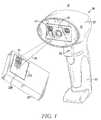
- FIG. 1is a perspective view of a portable scanner having at least one scan engine for imaging a target object;
- FIG. 2is a perspective view of a single scan engine used in either a portable or stationary bar code
- FIG. 3is a block diagram of the scan engine shown in FIG. 2 ;
- FIG. 4Ais an example of a 1D bar code
- FIG. 4Bis an example of a 2D bar code
- FIG. 5is a flowchart of an exemplary method of the disclosed system.
- the present disclosurerelates to a system for increasing the imaging quality in an imaging scanner.
- the system of the present disclosurecomprises an apparatus and method for increasing the imaging quality of an imaging scanner by use of a 2D bar code.
- the imaging system 10comprises a hand held portable scanner 26 that can be carried.
- One use of the imaging system 10is by a user walking or riding through a store, warehouse, or plant, while reading various symbology codes for stocking and inventory control purposes.
- the portable scanner 26 of FIG. 1includes a housing 13 having a head 28 , handle 30 , and trigger 32 . Located in the housing is a protective window 34 for protecting an imaging subsystem or scan engine 18 .
- the scan engine 18projects an aiming pattern 36 toward a target bar code 24 located on a product 20 or product's packaging during operation for decoding the image found in the target object.
- the operation of the decoding process by the scan engine 18is further described in U.S. application Ser. No. 11/647,877 having a filing date of Dec. 29, 2006 entitled IMAGING-BASED READER HAVING LIGHT GUIDED ILLUMINATION, which is assigned to the assignee of the present application and incorporated herein by reference.
- the scan engine 18comprises a chassis 38 and a front face 39 .
- a printed circuit board 40Connected to the chassis 38 along the front face 39 is a printed circuit board 40 .
- Attached to the printed circuit board 40are several optical components that include, illumination optics 42 , aiming optics 44 for generating the aiming pattern 36 , and imaging optics 46 .
- Each of the optical componentshave a designed field-of-view for projecting or receiving light directed during operation at the target object 24 .
- the optical components aboveare further secured to the printed circuit board 40 by surface objects 47 .
- various electrical components 49that assist the scan engine 18 in imaging and decoding the target object 24 .
- the imaging optics 46includes focusing lens or lenses 48 that focus the reflected image from the target object 24 onto a sensor array (not shown) located behind the focusing lens(es) and in front of the printed circuit board 40 .
- the aiming optics 44include a refractive or diffractive optical element 50 that facilitates in the projection of an aiming pattern 36 for aligning the scan engine with the target object 24 .
- the aiming patternis generated by a laser diode (not shown) located behind the optical element 50 and coupled to the printed circuit board 40 .
- the imaging optics 46captures an image frame of a field of view FV of the imaging system.
- the imaging processmay need to capture and store in a memory 134 a series of image frames 124 ( FIG. 3 ) in response to multiple user actuations of the trigger.
- a decoding system 130analyzes each image frame of the series of image frames 124 and attempts to decode the imaged bar code. All or portions of the images 132 are stored in a buffer memory 134 based on the results of this decoding.
- the imaging optics 46is coupled to the controller 100 .
- the imaging optics 46includes a housing supporting focusing optics including a focusing lens 48 and a 2D photosensor or pixel array 150 .
- the imaging optics 46is enabled during an imaging session to capture images of the field of view FV of the focusing lens 48 and that make up the image frames 124 .
- the bar code reader circuitry within the housing 13is electrically coupled to a power supply, which may be in the form of an on-board battery or a connected off-board power supply. If powered by an on-board battery, the reader 10 may be a stand-alone, portable unit as depicted in FIG. 1 . If powered by an off-board power supply, the reader 10 may have some or all of the reader's functionality provided by a connected host device. Circuitry associated with the imaging and decoding systems may be embodied in hardware, software, firmware, electrical circuitry or any combination thereof and may be disposed within, partially within, or external to the reader housing 13 .
- the sensor array 150may comprise a charged coupled device (CCD), a complementary metal oxide semiconductor (CMOS), or other imaging pixel array, operating under the control of the imaging circuitry 24 .
- the pixel array 150comprises a two dimensional (2D) mega pixel array with a typical size of the pixel array being on the order of 1280 ⁇ 1024 pixels.
- an imaging sessionmultiple images of the field of view FV may be obtained by the imaging system 10 .
- An imaging sessionmay be instituted by an operator, for example, pressing the trigger 32 to institute an imaging. Alternately, for a stationary imaging system, an imaging session might start when a lower or bottom edge of an item begin to move through a portion of the field of view FV.
- some or all of the pixels of pixel array 150are successively read out by the controller 100 , thereby generating an analog signal which is converted by an analog to digital converter that forms part of the controller 100 .
- all pixels of the pixel array 150are not exposed at the same time, thus, reading out of some pixels may coincide in time with an exposure period for some other pixels.
- the analog image signalrepresents a sequence of photosensor voltage values, the magnitude of each value representing an intensity of the reflected light received by a photosensor/pixel during an exposure period.
- the analog signal from the array 150is amplified by a gain factor, generating an amplified analog signal.
- the amplified analog signalis digitized by an A/D converter generating a digitized signal.
- FIGS. 1 and 4Adepicts a conventional 1D barcode 24 . If the user moves the housing 13 in relation to such a bar code such that the motion is parallel or along the direction of the elongated bars that make up the 1D bar code, the barcode will appear to be clear in the output image captured by the controller, but the rest of the picture or image that is captured is blurred. If decoding of a barcode signals the controller to output an image from a serial communications output port ( FIG. 3 ), for example, the blurred image is output. If the successful decoding of the barcode 24 causes the controller to merely store the image or a portion thereof, then that image will also be blurred.
- a serial communications output portFIG. 3
- One exemplary systemavoids blurring of images captured in response to trigger actuation by use of a 2D barcode on the object.
- a 2D bar code 25is depicted in FIGS. 3 and 4A . If there is relative movement between the reader and the target or object whose image is to be captured, there will be relative movement between the 2D barcode and the reader.
- the decode circuitry 140will only be able to decode the 2D barcode if the form or object is stationary. This process of avoiding image blur, requires a presence of a 2D bar code on the object or target.
- multiple 2D bar codesare spread through the form or object to reduce the error associated with the location of the output region of interest.
- the controller 100must detect and reject blurred output images in a different manner.
- the form contained in FIG. 3(a driver's license) contains at least two bounding boxes 210 , 212 which can be used to analyze if the image is blurred.
- the bar code of FIG. 3is a 1D barcode 24
- a bounding box 220is shown bounding the 1D barcode 24 which could represent either an object or a form on a document.
- the controller 100Based on a captured image, the controller 100 knows both the width and the height of the imaged bar code 24 , typically measured in terms of pixels of the sensor 150 . Input or stored and made accessible to the controller 100 is information regarding the width and height of the physical bar code 24 . typically measured in terms of module units. A module unit of measure is based on the smallest bar or unit of encoded information in the bar code. To determine a presence of blur, the controller 100 correlates the size of the physical bar code 24 in module units (e.g., the bar code 24 is 100 modules in width by 20 modules in height) to the size of the imaged original bar code in memory (e.g., the imaged bar code is 300 image pixels in width by 60 pixels in height).
- the size of the physical bar code 24 in module unitse.g., the bar code 24 is 100 modules in width by 20 modules in height
- the size of the imaged original bar code in memorye.g., the imaged bar code is 300 image pixels in width by 60 pixels in height.
- Information regarding physical characteristics regarding the form and the relative location and size of the bar code 24 imprinted thereonis typically provided by the form designer and is accessible to the controller in a controller memory. Alternately this information could be encoded in the barcode 24 and therefore accessible to the controller 100 on a successful decoding of the bar code.
- FIG. 5is a flowchart 230 of one alternate process the controller 100 uses to identify a blurred image.
- An imageis captured 232 and the controller 100 decodes the bar code and then determines a geometric center or center point of the imaged and successfully decoded target bar code whose image is stored in memory 134 . This is done by accessing 234 the information noted above regarding the size of the physical bar code 24 and data determined by the image processing system regarding the imaged bar code. Knowing the center point of the bar code, the controller determines a geometric center or center point of the imaged form 222 using information regarding the relationship between the center point of the physical bar code 24 and the location of the center point of the physical form 222 . As noted, this information is typically provided by the form designer.
- the image processing systemundertakes a search for the imaged border of the imaged form utilizing one or more box search techniques 236 such as edge detection and/or line tracking.
- box search techniques 236such as edge detection and/or line tracking.
- One such processdetermines the location of the corners of the border or bounding box within the image and determines if the image at these pixel locations are sufficiently dark within the grey scale stored image. To make the process even more reliable the corners and pixel locations in close proximity to the corners that should correspond to locations within the lines of the bounding box are checked.
- the orientation of these linesare known, for example due to the fact that the orientation of the bar code 24 is known.
- step 238Assuming that horizontal and vertical sections or segments of the imaged border are found at step 238 , all or part of the image is stored 240 . If validation does not occur another image is captured 232 .
- the controller 100can judge the degree of uniformity of the bounding box around its perimeter or a portion of its perimeter. If an outer edge of a bounding box forms a line within limits, i.e. from the endpoints of the line no pixel of the boundary deviates from its calculated position based on its length from the ends, then the bounding box is bordered by a line and the image will not be blurred. Text characters can also be analyzed for clarity in a similar manner.
- a common characteristic of all three processesis the presence of generally orthogonal lines whose straightness can be judged by the imaging system 10 .
- the codeis made up of small m by n rectangular units having orthogonal sides.
- the decoding circuitryIn determining the blurriness of the image, the decoding circuitry must be able to identify the boundaries in the bar code just as in identifying a bounding box it must be able to correctly discern the presence of the bounding box.
Landscapes
- Physics & Mathematics (AREA)
- Electromagnetism (AREA)
- Engineering & Computer Science (AREA)
- Health & Medical Sciences (AREA)
- General Health & Medical Sciences (AREA)
- Toxicology (AREA)
- Artificial Intelligence (AREA)
- Computer Vision & Pattern Recognition (AREA)
- General Physics & Mathematics (AREA)
- Theoretical Computer Science (AREA)
- Image Input (AREA)
Abstract
Description
Claims (9)
Priority Applications (1)
| Application Number | Priority Date | Filing Date | Title |
|---|---|---|---|
| US12/624,071US8167209B2 (en) | 2009-11-23 | 2009-11-23 | Increasing imaging quality of a bar code reader |
Applications Claiming Priority (1)
| Application Number | Priority Date | Filing Date | Title |
|---|---|---|---|
| US12/624,071US8167209B2 (en) | 2009-11-23 | 2009-11-23 | Increasing imaging quality of a bar code reader |
Publications (2)
| Publication Number | Publication Date |
|---|---|
| US20110121077A1 US20110121077A1 (en) | 2011-05-26 |
| US8167209B2true US8167209B2 (en) | 2012-05-01 |
Family
ID=44061367
Family Applications (1)
| Application Number | Title | Priority Date | Filing Date |
|---|---|---|---|
| US12/624,071Active2030-08-06US8167209B2 (en) | 2009-11-23 | 2009-11-23 | Increasing imaging quality of a bar code reader |
Country Status (1)
| Country | Link |
|---|---|
| US (1) | US8167209B2 (en) |
Cited By (5)
| Publication number | Priority date | Publication date | Assignee | Title |
|---|---|---|---|---|
| US20110135144A1 (en)* | 2009-07-01 | 2011-06-09 | Hand Held Products, Inc. | Method and system for collecting voice and image data on a remote device and coverting the combined data |
| USD692004S1 (en)* | 2012-08-31 | 2013-10-22 | Megaviz Limited | Barcode scanner and radio frequency identification reader combo |
| USD726186S1 (en)* | 2013-10-25 | 2015-04-07 | Symbol Technologies, Inc. | Scanner |
| USD844005S1 (en)* | 2016-12-23 | 2019-03-26 | Novadaq Technologies ULC | Device for illumination and imaging of a target |
| USD1065550S1 (en) | 2016-04-28 | 2025-03-04 | Stryker Corporation | Device for illumination and imaging of a target |
Families Citing this family (12)
| Publication number | Priority date | Publication date | Assignee | Title |
|---|---|---|---|---|
| US9524411B2 (en)* | 2010-03-04 | 2016-12-20 | Symbol Technologies, Llc | User-customizable data capture terminal for and method of imaging and processing a plurality of target data on one or more targets |
| US20120104099A1 (en)* | 2010-10-27 | 2012-05-03 | Symbol Technologies, Inc. | Method and apparatus for capturing form document with imaging scanner |
| US9208366B2 (en)* | 2011-06-08 | 2015-12-08 | Metrologic Instruments, Inc. | Indicia decoding device with security lock |
| US9679176B2 (en)* | 2011-06-08 | 2017-06-13 | Metrologic Instruments, Inc. | Indicia decoding device with security lock |
| US9424480B2 (en)* | 2012-04-20 | 2016-08-23 | Datalogic ADC, Inc. | Object identification using optical code reading and object recognition |
| USD982585S1 (en) | 2013-12-05 | 2023-04-04 | Hand Held Products, Inc. | Indicia scanner |
| USD734339S1 (en)* | 2013-12-05 | 2015-07-14 | Hand Held Products, Inc. | Indicia scanner |
| USD826234S1 (en) | 2016-04-11 | 2018-08-21 | Hand Held Products, Inc. | Indicia scanner |
| USD737822S1 (en)* | 2014-03-10 | 2015-09-01 | Datalogic Ip Tech S.R.L. | Optical module |
| USD805078S1 (en) | 2015-05-07 | 2017-12-12 | Datalogic Ip Tech S.R.L. | Barcode reading module |
| USD791137S1 (en)* | 2015-07-22 | 2017-07-04 | Hand Held Products, Inc. | Scanner |
| US11321545B2 (en)* | 2020-06-30 | 2022-05-03 | Datalogic IP Tech, S.r.l. | Barcode scanner system with animated feedback |
Citations (5)
| Publication number | Priority date | Publication date | Assignee | Title |
|---|---|---|---|---|
| US6572019B1 (en)* | 1994-07-19 | 2003-06-03 | Psc Scanning, Inc. | Compact scanner module mountable to pointing instrument |
| US20050017078A1 (en)* | 2003-07-23 | 2005-01-27 | Sudhir Bhatia | Mobile terminal with handle that houses a stylus |
| US6976632B2 (en)* | 1990-09-17 | 2005-12-20 | Metrologic Instruments Inc. | Automatic hand-supportable laser scanner and method of reading bar code symbols using same |
| US20060163356A1 (en)* | 2005-01-26 | 2006-07-27 | Denso Wave Incorporated | Information reading apparatus with a screen for displaying stored symbol images |
| US20100155487A1 (en)* | 2008-12-19 | 2010-06-24 | Rong Liu | Illumination Apparatus for An Imaging-Based Bar Code System |
- 2009
- 2009-11-23USUS12/624,071patent/US8167209B2/enactiveActive
Patent Citations (5)
| Publication number | Priority date | Publication date | Assignee | Title |
|---|---|---|---|---|
| US6976632B2 (en)* | 1990-09-17 | 2005-12-20 | Metrologic Instruments Inc. | Automatic hand-supportable laser scanner and method of reading bar code symbols using same |
| US6572019B1 (en)* | 1994-07-19 | 2003-06-03 | Psc Scanning, Inc. | Compact scanner module mountable to pointing instrument |
| US20050017078A1 (en)* | 2003-07-23 | 2005-01-27 | Sudhir Bhatia | Mobile terminal with handle that houses a stylus |
| US20060163356A1 (en)* | 2005-01-26 | 2006-07-27 | Denso Wave Incorporated | Information reading apparatus with a screen for displaying stored symbol images |
| US20100155487A1 (en)* | 2008-12-19 | 2010-06-24 | Rong Liu | Illumination Apparatus for An Imaging-Based Bar Code System |
Cited By (6)
| Publication number | Priority date | Publication date | Assignee | Title |
|---|---|---|---|---|
| US20110135144A1 (en)* | 2009-07-01 | 2011-06-09 | Hand Held Products, Inc. | Method and system for collecting voice and image data on a remote device and coverting the combined data |
| USD692004S1 (en)* | 2012-08-31 | 2013-10-22 | Megaviz Limited | Barcode scanner and radio frequency identification reader combo |
| USD726186S1 (en)* | 2013-10-25 | 2015-04-07 | Symbol Technologies, Inc. | Scanner |
| USD1065550S1 (en) | 2016-04-28 | 2025-03-04 | Stryker Corporation | Device for illumination and imaging of a target |
| USD844005S1 (en)* | 2016-12-23 | 2019-03-26 | Novadaq Technologies ULC | Device for illumination and imaging of a target |
| USD989075S1 (en) | 2016-12-23 | 2023-06-13 | Stryker European Operations Limited | Device for illumination and imaging of a target |
Also Published As
| Publication number | Publication date |
|---|---|
| US20110121077A1 (en) | 2011-05-26 |
Similar Documents
| Publication | Publication Date | Title |
|---|---|---|
| US8167209B2 (en) | Increasing imaging quality of a bar code reader | |
| US8910872B2 (en) | Imaging reader and method with dual function illumination light assembly | |
| US7854385B2 (en) | Automatic region of interest focusing for an imaging-based bar code reader | |
| EP2507741B1 (en) | Imaging-based scanner including border searching for image acquisition | |
| US8534556B2 (en) | Arrangement for and method of reducing vertical parallax between an aiming pattern and an imaging field of view in a linear imaging reader | |
| US20060038017A1 (en) | Automatic focusing system for imaging-based bar code reader | |
| US9800749B1 (en) | Arrangement for, and method of, expeditiously adjusting reading parameters of an imaging reader based on target distance | |
| EP2460116B1 (en) | Method of setting amount of exposure for photodetector array in barcode scanner | |
| US20150242669A1 (en) | Optimizing focus plane position of imaging scanner | |
| US8864036B2 (en) | Apparatus and method for finding target distance from barode imaging scanner | |
| US8985462B2 (en) | Method of driving focusing element in barcode imaging scanner | |
| EP3039612B1 (en) | Method of controlling exposure on barcode imaging scanner with rolling shutter sensor | |
| US20130161392A1 (en) | Aiming method for rolling shutter image sensors | |
| US11009347B2 (en) | Arrangement for, and method of, determining a distance to a target to be read by image capture over a range of working distances | |
| US9646188B1 (en) | Imaging module and reader for, and method of, expeditiously setting imaging parameters of an imager based on the imaging parameters previously set for a default imager | |
| US10140497B1 (en) | Methods and system for reading barcodes captured on multiple images | |
| EP2449504B1 (en) | Method and apparatus for defining illumination field of view of barcode reader | |
| WO2017205065A1 (en) | Arrangement for, and method of, determining a target distance and adjusting reading parameters of an imaging reader based on target distance | |
| US8960550B2 (en) | Minimizing misdecodes in electro-optical readers | |
| EP2140398B1 (en) | Image enhancement in imaging system | |
| US9213880B2 (en) | Method of optimizing focus plane position of imaging scanner | |
| US12430524B1 (en) | Method of compensating illuminance variation due to skew and pitched field of view from a handheld scanner | |
| US8840025B2 (en) | Arrangement for and method of preventing symbol misreads in electro-optical readers | |
| US8376234B2 (en) | Method of and reader for electro-optically reading symbols on curved surfaces |
Legal Events
| Date | Code | Title | Description |
|---|---|---|---|
| AS | Assignment | Owner name:SYMBOL TECHNOLOGIES, INC., NEW YORK Free format text:ASSIGNMENT OF ASSIGNORS INTEREST;ASSIGNORS:JOSEPH, EUGENE, MR.;HE, DUANFENG, MR.;REEL/FRAME:023559/0130 Effective date:20091123 | |
| STCF | Information on status: patent grant | Free format text:PATENTED CASE | |
| AS | Assignment | Owner name:MORGAN STANLEY SENIOR FUNDING, INC. AS THE COLLATERAL AGENT, MARYLAND Free format text:SECURITY AGREEMENT;ASSIGNORS:ZIH CORP.;LASER BAND, LLC;ZEBRA ENTERPRISE SOLUTIONS CORP.;AND OTHERS;REEL/FRAME:034114/0270 Effective date:20141027 Owner name:MORGAN STANLEY SENIOR FUNDING, INC. AS THE COLLATE Free format text:SECURITY AGREEMENT;ASSIGNORS:ZIH CORP.;LASER BAND, LLC;ZEBRA ENTERPRISE SOLUTIONS CORP.;AND OTHERS;REEL/FRAME:034114/0270 Effective date:20141027 | |
| AS | Assignment | Owner name:SYMBOL TECHNOLOGIES, LLC, NEW YORK Free format text:CHANGE OF NAME;ASSIGNOR:SYMBOL TECHNOLOGIES, INC.;REEL/FRAME:036083/0640 Effective date:20150410 | |
| AS | Assignment | Owner name:SYMBOL TECHNOLOGIES, INC., NEW YORK Free format text:RELEASE BY SECURED PARTY;ASSIGNOR:MORGAN STANLEY SENIOR FUNDING, INC.;REEL/FRAME:036371/0738 Effective date:20150721 | |
| FPAY | Fee payment | Year of fee payment:4 | |
| MAFP | Maintenance fee payment | Free format text:PAYMENT OF MAINTENANCE FEE, 8TH YEAR, LARGE ENTITY (ORIGINAL EVENT CODE: M1552); ENTITY STATUS OF PATENT OWNER: LARGE ENTITY Year of fee payment:8 | |
| MAFP | Maintenance fee payment | Free format text:PAYMENT OF MAINTENANCE FEE, 12TH YEAR, LARGE ENTITY (ORIGINAL EVENT CODE: M1553); ENTITY STATUS OF PATENT OWNER: LARGE ENTITY Year of fee payment:12 |