US8166851B2 - Combination driving tool for phillips and robertson fasteners - Google Patents
Combination driving tool for phillips and robertson fastenersDownload PDFInfo
- Publication number
- US8166851B2 US8166851B2US12/475,933US47593309AUS8166851B2US 8166851 B2US8166851 B2US 8166851B2US 47593309 AUS47593309 AUS 47593309AUS 8166851 B2US8166851 B2US 8166851B2
- Authority
- US
- United States
- Prior art keywords
- bit
- driving tool
- driving
- ribs
- head fastener
- Prior art date
- Legal status (The legal status is an assumption and is not a legal conclusion. Google has not performed a legal analysis and makes no representation as to the accuracy of the status listed.)
- Active, expires
Links
Images


Classifications
- B—PERFORMING OPERATIONS; TRANSPORTING
- B25—HAND TOOLS; PORTABLE POWER-DRIVEN TOOLS; MANIPULATORS
- B25B—TOOLS OR BENCH DEVICES NOT OTHERWISE PROVIDED FOR, FOR FASTENING, CONNECTING, DISENGAGING OR HOLDING
- B25B15/00—Screwdrivers
- B—PERFORMING OPERATIONS; TRANSPORTING
- B25—HAND TOOLS; PORTABLE POWER-DRIVEN TOOLS; MANIPULATORS
- B25B—TOOLS OR BENCH DEVICES NOT OTHERWISE PROVIDED FOR, FOR FASTENING, CONNECTING, DISENGAGING OR HOLDING
- B25B15/00—Screwdrivers
- B25B15/001—Screwdrivers characterised by material or shape of the tool bit
- B25B15/004—Screwdrivers characterised by material or shape of the tool bit characterised by cross-section
- B25B15/005—Screwdrivers characterised by material or shape of the tool bit characterised by cross-section with cross- or star-shaped cross-section
- B—PERFORMING OPERATIONS; TRANSPORTING
- B25—HAND TOOLS; PORTABLE POWER-DRIVEN TOOLS; MANIPULATORS
- B25B—TOOLS OR BENCH DEVICES NOT OTHERWISE PROVIDED FOR, FOR FASTENING, CONNECTING, DISENGAGING OR HOLDING
- B25B13/00—Spanners; Wrenches
- B25B13/02—Spanners; Wrenches with rigid jaws
- B25B13/06—Spanners; Wrenches with rigid jaws of socket type
- B—PERFORMING OPERATIONS; TRANSPORTING
- B25—HAND TOOLS; PORTABLE POWER-DRIVEN TOOLS; MANIPULATORS
- B25B—TOOLS OR BENCH DEVICES NOT OTHERWISE PROVIDED FOR, FOR FASTENING, CONNECTING, DISENGAGING OR HOLDING
- B25B15/00—Screwdrivers
- B25B15/001—Screwdrivers characterised by material or shape of the tool bit
- B25B15/004—Screwdrivers characterised by material or shape of the tool bit characterised by cross-section
- B25B15/008—Allen-type keys
- B—PERFORMING OPERATIONS; TRANSPORTING
- B25—HAND TOOLS; PORTABLE POWER-DRIVEN TOOLS; MANIPULATORS
- B25B—TOOLS OR BENCH DEVICES NOT OTHERWISE PROVIDED FOR, FOR FASTENING, CONNECTING, DISENGAGING OR HOLDING
- B25B15/00—Screwdrivers
- B25B15/02—Screwdrivers operated by rotating the handle
- B—PERFORMING OPERATIONS; TRANSPORTING
- B25—HAND TOOLS; PORTABLE POWER-DRIVEN TOOLS; MANIPULATORS
- B25B—TOOLS OR BENCH DEVICES NOT OTHERWISE PROVIDED FOR, FOR FASTENING, CONNECTING, DISENGAGING OR HOLDING
- B25B17/00—Hand-driven gear-operated wrenches or screwdrivers
- B—PERFORMING OPERATIONS; TRANSPORTING
- B25—HAND TOOLS; PORTABLE POWER-DRIVEN TOOLS; MANIPULATORS
- B25B—TOOLS OR BENCH DEVICES NOT OTHERWISE PROVIDED FOR, FOR FASTENING, CONNECTING, DISENGAGING OR HOLDING
- B25B23/00—Details of, or accessories for, spanners, wrenches, screwdrivers
- F—MECHANICAL ENGINEERING; LIGHTING; HEATING; WEAPONS; BLASTING
- F16—ENGINEERING ELEMENTS AND UNITS; GENERAL MEASURES FOR PRODUCING AND MAINTAINING EFFECTIVE FUNCTIONING OF MACHINES OR INSTALLATIONS; THERMAL INSULATION IN GENERAL
- F16B—DEVICES FOR FASTENING OR SECURING CONSTRUCTIONAL ELEMENTS OR MACHINE PARTS TOGETHER, e.g. NAILS, BOLTS, CIRCLIPS, CLAMPS, CLIPS OR WEDGES; JOINTS OR JOINTING
- F16B23/00—Specially shaped nuts or heads of bolts or screws for rotations by a tool
Definitions
- the present inventiongenerally relates to drivers for driving threaded fasteners having various head configurations.
- the Phillips head screwsas well as the Robertson® screws.
- the recess of the Phillips headis the well known cross slotted configuration which is defined by ISO standard 8764-2004(E), and is shown in the inspection gauge of FIG. 3 thereof, which is specifically incorporated by reference herein.
- the Phillips head recessdoes not experience the easy disengagement of the screwdriver as compared to a single slotted head because the bit is captured on all sides within the recess.
- the Robertson® recessis defined in the Draft revision ASME B13.6.3 2002 standard for type III pan head machine screws, and also specifically incorporated by reference herein.
- the Robertson® configuration square recessalso captures the driver on all sides.
- Drivershave been designed and commercialized which are capable of driving more than one configuration of a threaded fastener, such as a slotted head and a Phillips head. Such combination drivers can be convenient for a user if the combination can effectively engage more than one type of head configuration, because a single driver rather than multiple ones can be used.
- a combination driver that is effective to drive both Phillips head screws and Robertson® screwswould be highly desirable and is not known to be commercially available.
- Embodiments of a driving toolcomprise a shank portion, and a working portion, wherein the working portion is configured to drive either a Phillips head fastener or a Robertson® head fastener.
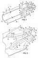
- FIG. 1is a perspective view of a preferred embodiment of a combination bit that is capable of driving both Phillips head and Robertson® head screws and fasteners;
- FIG. 2is an enlargement of a tip or working portion of the combination bit shown in FIG. 1 ;
- FIG. 3is a plan view of the combination bit shown in FIG. 1 ;
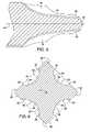
- FIG. 4is an end view of the tip portion of the combination bit shown in FIG. 1 ;
- FIG. 5is a cross section taken generally along the line 5 - 5 of FIG. 4 ;
- FIG. 6is a cross section taken generally along the line 6 - 6 of FIG. 3 ;
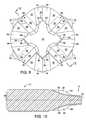
- FIG. 7is a perspective view of an alternative embodiment of a combination bit that is capable of driving both Phillips head and Robertson® head screws and fasteners;
- FIG. 8is a side plan view of the alternative combination bit shown in FIG. 7 ;
- FIG. 9is a end view of the tip portion of the combination bit shown in FIG. 7 ;
- FIG. 10is a cross section taken generally along the line 10 - 10 of FIG. 9 .
- FIG. 1Two embodiments of the present invention are shown in the drawings, both of which are directed to a combination bit that is capable of driving threaded fasteners and screws that have a Phillips head portion or a Robertson® head portion.
- the drawingsall show a combination bit that has a hexagonal shank which is configured to be held in a socket of some type of tool which may be a manual screwdriver with a screwdriver handle, or it may fit in a socket that is a part of a pneumatic driven wrench or an electrically driven tool or other type of tool.
- shank of the bits that are illustratedcould be a long shaft attached to a handle with a working portion or tip that is configured to drive the Phillips head or Robertson® head screws or other fasteners.
- the combination bitis indicated generally at 10 and includes a shank portion, indicated generally at 12 and a working portion or tip indicated generally at 14 .
- the shank portion 12may have any one of many different configurations, including a cylindrical shape, it is preferred that it have a hexagonal cross section with six flat faces 16 with adjacent faces having a narrow flat portion 18 at the intersection thereof. It is also preferred that the flat portions have notches 20 for interfacing with a quick connect adaptor which secures the bit in a socket tool.
- the outer circumference 22 of the free end of the shank portion 12is chamfered to facilitate easy insertion of the bit into a suitable socket.
- the illustrated shankis preferably a standard insert bit shank per DIN 3126 form C6.3.
- each of the ribshas side walls 30 on opposite side portions that extend from a front location 32 where it terminates at the end surface 24 to the other end where it terminates near the outer surface of the shank portion 12 as identified at 34 .
- the side walls 30are generally planar with the distance between the walls being generally slightly smaller than the width of the slots in a Phillips head configuration recess.
- the flutes 28also have a bottom trough section that is generally shown to have trough side portions 36 as well as a center bottom line 38 .
- the drawingsare line drawings are slightly exaggerated for the sake of clarity.
- the two trough side portions 36 as well as the center bottom line 38may be curved relative to one another and the interface between the side walls 30 and the trough side portions 36 may also be gently curved, which smoothing is consistent with the actual shape of many Phillips head screwdriver tips.
- ribs 26extend from the end surface 24 to the shank portion 12 and have an angled flat face 40 that is approximately at an angle of 26° relative to a longitudinal center axis 42 of the bit.
- the flat face 40extends to a pair of side panels 44 which gently curve to terminate at an approximately 26° angle relative to the face 16 of the shank portion.
- a dotted line 46identifies a transition portion where the side panels 44 on the ribs 26 extending toward the tip end surface 24 are essentially planar and tapered inward toward the center axis 42 of the bit 10 at an approximate angle of 2.5 degrees.
- the side panels 44then curve outwardly as shown in FIGS. 1 and 2 as they extend to the shank portion flat faces 16 .
- the segments between the line 46 and the angled flat surface 40identified at 48 , present planar segments that are parallel to the center axis 42 and substantially perpendicular to one another in the axial direction, as can be seen in the cross section shown in FIG. 6 .
- These panel segments 48 of each of the four ribs 26form a square as shown in FIG. 6 which is slightly smaller than the recess of a Robertson® head fastener.
- the geometryis such that the panel segments 48 are oriented to contact the inside surfaces of the recess for driving a Robertson® screw or fastener.
- FIGS. 7-10another combination bit is shown which is also configured to drive a Phillips head fastener as well as a Robertson® fastener.
- the reference numbers that have been applied to the first preferred embodimentare repeated for corresponding surfaces and shapes in the alternative embodiment, but slight differences in the configuration will be apparent.
- the major differencesare that the working portion 14 has a base portion, indicated generally at 50 , which is cylindrical in shape so that there is a transition from the circular base portion 50 to the hexagonal shank portion 12 that is not present in the embodiment shown in FIGS. 1-6 . Therefore, the flutes 28 terminate in the cylindrical base portion 50 rather than in the sides faces 16 of the hexagonal shank portion.
- the tip or working portion 14 as shown in FIGS. 7-10is also more severely truncated in that the end surface 24 has a larger surface area and in fact approximates the size of the transition portion 46 to present a greater surface area for the panel segments 48 that engage the interior walls of the Robertson® cubic recess.
Landscapes
- Engineering & Computer Science (AREA)
- Mechanical Engineering (AREA)
- General Engineering & Computer Science (AREA)
- Details Of Spanners, Wrenches, And Screw Drivers And Accessories (AREA)
- Portable Nailing Machines And Staplers (AREA)
- Knives (AREA)
- Earth Drilling (AREA)
- Drilling Tools (AREA)
Abstract
Description
Claims (19)
Priority Applications (2)
| Application Number | Priority Date | Filing Date | Title |
|---|---|---|---|
| US12/475,933US8166851B2 (en) | 2008-08-15 | 2009-06-01 | Combination driving tool for phillips and robertson fasteners |
| TW098123336ATWI540025B (en) | 2008-08-15 | 2009-07-10 | A combination driving tool for phillips and robertson fasteners |
Applications Claiming Priority (2)
| Application Number | Priority Date | Filing Date | Title |
|---|---|---|---|
| US8933708P | 2008-08-15 | 2008-08-15 | |
| US12/475,933US8166851B2 (en) | 2008-08-15 | 2009-06-01 | Combination driving tool for phillips and robertson fasteners |
Publications (2)
| Publication Number | Publication Date |
|---|---|
| US20100037737A1 US20100037737A1 (en) | 2010-02-18 |
| US8166851B2true US8166851B2 (en) | 2012-05-01 |
Family
ID=40984674
Family Applications (1)
| Application Number | Title | Priority Date | Filing Date |
|---|---|---|---|
| US12/475,933Active2030-04-10US8166851B2 (en) | 2008-08-15 | 2009-06-01 | Combination driving tool for phillips and robertson fasteners |
Country Status (8)
| Country | Link |
|---|---|
| US (1) | US8166851B2 (en) |
| EP (1) | EP2326463B1 (en) |
| JP (1) | JP5739805B2 (en) |
| KR (1) | KR101636585B1 (en) |
| CN (1) | CN102123831B (en) |
| AT (1) | ATE551157T1 (en) |
| TW (1) | TWI540025B (en) |
| WO (1) | WO2010019352A1 (en) |
Cited By (32)
| Publication number | Priority date | Publication date | Assignee | Title |
|---|---|---|---|---|
| US20130276595A1 (en)* | 2012-04-23 | 2013-10-24 | Tsai-Fa Liu | Universal anti-torque screwdriver head structure |
| US20140150613A1 (en)* | 2012-12-05 | 2014-06-05 | Burton Kozak | Torx Head Bit |
| US8984991B1 (en)* | 2013-04-23 | 2015-03-24 | Brad A. English | Fastener removal device for dirty environments |
| US9156147B2 (en) | 2012-02-15 | 2015-10-13 | Black & Decker Inc. | Quick change bit holder with ring magnet |
| US9227309B2 (en) | 2012-02-15 | 2016-01-05 | Black & Decker Inc. | Quick change bit holder with ring magnet |
| US9505108B2 (en) | 2012-02-15 | 2016-11-29 | Black & Decker Inc. | Bit holder with floating magnet sleeve |
| USD789761S1 (en) | 2015-11-02 | 2017-06-20 | Black & Decker Inc. | Torsion bit |
| US9943946B2 (en) | 2012-02-15 | 2018-04-17 | Black & Decker Inc. | Tool bits with floating magnet sleeves |
| US10150205B2 (en) | 2012-02-15 | 2018-12-11 | Black & Decker Inc. | Fastening tools with floating magnet sleeves |
| USD855433S1 (en) | 2017-08-09 | 2019-08-06 | Milwaukee Electric Tool Corporation | Screwdriver |
| USD900893S1 (en) | 2016-03-15 | 2020-11-03 | Brad A. English | Jagged tooth head fastener removal device for dirty environments |
| WO2021019500A1 (en)* | 2019-07-30 | 2021-02-04 | Grip Holdings Llc | Advanced holding apparatus |
| US11059162B2 (en) | 2017-05-17 | 2021-07-13 | Milwaukee Electric Tool Corporation | Screwdriver |
| US11154969B2 (en) | 2016-04-27 | 2021-10-26 | Grip Holdings Llc | Fastener extractor device |
| US11161234B2 (en) | 2018-03-15 | 2021-11-02 | Grip Holdings Llc | Tool holding apparatus |
| USD966063S1 (en) | 2018-03-07 | 2022-10-11 | Grip Holdings Llc | Socket |
| USD973736S1 (en)* | 2020-04-09 | 2022-12-27 | Arbortech Industries Limited | Rotary carving tool |
| US11590637B2 (en) | 2017-04-27 | 2023-02-28 | Grip Holdings Llc | Methods and apparatuses for extracting and dislodging fasteners |
| US11602828B2 (en) | 2019-07-30 | 2023-03-14 | Grip Holdings Llc | Multi-grip screw apparatus |
| USD983241S1 (en) | 2020-04-09 | 2023-04-11 | Arbortech Industries Limited | Rotary carving tool |
| US20230182274A1 (en)* | 2017-03-23 | 2023-06-15 | Grip Holdings Llc | Advanced Holding Apparatus |
| US11701757B2 (en) | 2018-09-19 | 2023-07-18 | Grip Holdings Llc | Anti-slip fastener remover tool |
| US11759918B2 (en) | 2019-05-09 | 2023-09-19 | Grip Holdings Llc | Anti-slip torque tool with integrated engagement features |
| US11897099B2 (en) | 2018-09-19 | 2024-02-13 | Grip Holdings Llc | Fastener extractor and dislodging tool apparatus |
| USD1026602S1 (en) | 2022-03-17 | 2024-05-14 | Grip Holdings Llc | Selectable twist tool |
| US12023786B2 (en) | 2017-02-15 | 2024-07-02 | Grip Holdings Llc | Multi-directional driver bit |
| USD1042059S1 (en) | 2022-02-25 | 2024-09-17 | Grip Holdings Llc | Percussion drive |
| USD1072207S1 (en) | 2022-08-25 | 2025-04-22 | Dana Italia S.R.L. | Oil plug |
| US12296440B2 (en) | 2019-04-12 | 2025-05-13 | Grip Holdings Llc | Anti-slip multidirectional fastener remover tool |
| US12337449B2 (en) | 2017-07-14 | 2025-06-24 | Grip Holdings Llc | Foreign object removal socket adapter |
| US12403574B2 (en) | 2016-04-27 | 2025-09-02 | Grip Holdings Llc | Fastener extractor device |
| US12434360B2 (en) | 2017-03-23 | 2025-10-07 | Grip Holdings Llc | Advanced holding apparatus |
Families Citing this family (9)
| Publication number | Priority date | Publication date | Assignee | Title |
|---|---|---|---|---|
| CN103282162B (en)* | 2010-07-07 | 2017-10-13 | 英法斯泰克知识产权私人有限公司 | Torque transmission driver |
| US20180117743A1 (en)* | 2015-02-18 | 2018-05-03 | Daniel L. Pinckard | Rotational Tool Bit |
| EP3472475A1 (en)* | 2016-06-17 | 2019-04-24 | Phillips Screw Company | High strength fasteners, drivers, and fastener systems |
| US20190193253A1 (en)* | 2017-12-22 | 2019-06-27 | Andrew John FORAN | Anti-Slip Screwdriver Bit |
| USD983003S1 (en)* | 2017-12-24 | 2023-04-11 | IPP industries Sàrl | Screw driver bit |
| CA3126890C (en)* | 2019-01-23 | 2023-10-17 | Grip Holdings Llc | Anti-slip fastener remover tool |
| DE102020133061A1 (en)* | 2020-12-10 | 2022-06-15 | Berner Trading Holding Gmbh | Screwdriver drive geometry, screw bit and screw head |
| WO2022220850A1 (en) | 2021-04-15 | 2022-10-20 | Grip Holdings Llc | Anti-slip fastener remover tool |
| WO2024025685A1 (en)* | 2022-07-26 | 2024-02-01 | Grip Holdings Llc | Anti-slip fastener remover tool |
Citations (19)
| Publication number | Priority date | Publication date | Assignee | Title |
|---|---|---|---|---|
| US2046838A (en) | 1934-07-03 | 1936-07-07 | Phillips Screw Co | Screw driver |
| US2046837A (en) | 1934-07-03 | 1936-07-07 | Phillips Screw Co | Means for uniting a screw with a driver |
| US2046840A (en) | 1935-01-15 | 1936-07-07 | Phillips Screw Co | Screw driver |
| US2046343A (en) | 1934-07-03 | 1936-07-07 | Phillips Screw Co | Screw |
| US2116775A (en) | 1936-03-03 | 1938-05-10 | George P Blackburn | Screw driver |
| US2182568A (en) | 1937-04-15 | 1939-12-05 | Illinois Tool Works | Screw |
| US2366682A (en)* | 1942-04-01 | 1945-01-02 | Champion Inc | Screw driver bit |
| US3396765A (en) | 1966-10-03 | 1968-08-13 | Gen Motors Corp | Screw and driver |
| US4089357A (en)* | 1975-07-19 | 1978-05-16 | G.K.N. Fasteners Limited | Threaded fastener |
| US4488462A (en) | 1981-11-09 | 1984-12-18 | Wall Stanford J | Screwdriver with dual tip |
| US5020954A (en) | 1981-03-30 | 1991-06-04 | Intools, Limited | Screw driving socket |
| US5358368A (en) | 1993-09-09 | 1994-10-25 | General Signal Corporation | Screw with improved head design |
| US6164171A (en)* | 1998-03-13 | 2000-12-26 | Max Co., Ltd. | Screwdriver used for screw tightener and screw suitably tightened by the screwdriver |
| US6289775B1 (en) | 1998-11-17 | 2001-09-18 | Lin Chao Wei | Screw driver with four fan-shaped blades |
| US6352011B1 (en) | 2000-08-11 | 2002-03-05 | Fruehm Hermann | Two-ended screwdriver bits |
| US6584876B2 (en)* | 1996-10-24 | 2003-07-01 | Katsuyuki Totsu | Screw, driver bit and header punch for manufacture of screw |
| WO2004065802A1 (en) | 2003-01-21 | 2004-08-05 | Bernard Tanner | Screw and corresponding driver |
| US6843729B2 (en) | 2002-02-26 | 2005-01-18 | Phillips Screw Company | Fastener having recess useable with multiple drivers and method of manufacture |
| WO2006130490A1 (en) | 2005-05-27 | 2006-12-07 | Synthes (U.S.A.) | Combination driver and combination fastener for hexagonal and lobed-head fastening systems |
Family Cites Families (2)
| Publication number | Priority date | Publication date | Assignee | Title |
|---|---|---|---|---|
| JPH10202547A (en)* | 1997-01-28 | 1998-08-04 | Wessel Kogyo:Kk | Screwdriver bit |
| JP3334748B2 (en)* | 1998-03-13 | 2002-10-15 | マックス株式会社 | Driver bit structure and screw recess structure |
- 2009
- 2009-06-01USUS12/475,933patent/US8166851B2/enactiveActive
- 2009-07-10TWTW098123336Apatent/TWI540025B/enactive
- 2009-07-20JPJP2011523027Apatent/JP5739805B2/enactiveActive
- 2009-07-20CNCN200980131709.2Apatent/CN102123831B/enactiveActive
- 2009-07-20WOPCT/US2009/051127patent/WO2010019352A1/enactiveApplication Filing
- 2009-07-20ATAT09790630Tpatent/ATE551157T1/enactive
- 2009-07-20EPEP09790630Apatent/EP2326463B1/enactiveActive
- 2009-07-20KRKR1020107005941Apatent/KR101636585B1/enactiveActive
Patent Citations (22)
| Publication number | Priority date | Publication date | Assignee | Title |
|---|---|---|---|---|
| US2046838A (en) | 1934-07-03 | 1936-07-07 | Phillips Screw Co | Screw driver |
| US2046837A (en) | 1934-07-03 | 1936-07-07 | Phillips Screw Co | Means for uniting a screw with a driver |
| US2046343A (en) | 1934-07-03 | 1936-07-07 | Phillips Screw Co | Screw |
| US2046840A (en) | 1935-01-15 | 1936-07-07 | Phillips Screw Co | Screw driver |
| US2116775A (en) | 1936-03-03 | 1938-05-10 | George P Blackburn | Screw driver |
| US2182568A (en) | 1937-04-15 | 1939-12-05 | Illinois Tool Works | Screw |
| US2366682A (en)* | 1942-04-01 | 1945-01-02 | Champion Inc | Screw driver bit |
| US3396765A (en) | 1966-10-03 | 1968-08-13 | Gen Motors Corp | Screw and driver |
| US4089357A (en)* | 1975-07-19 | 1978-05-16 | G.K.N. Fasteners Limited | Threaded fastener |
| US5020954A (en) | 1981-03-30 | 1991-06-04 | Intools, Limited | Screw driving socket |
| US4488462A (en) | 1981-11-09 | 1984-12-18 | Wall Stanford J | Screwdriver with dual tip |
| US5358368A (en) | 1993-09-09 | 1994-10-25 | General Signal Corporation | Screw with improved head design |
| US6584876B2 (en)* | 1996-10-24 | 2003-07-01 | Katsuyuki Totsu | Screw, driver bit and header punch for manufacture of screw |
| US6164171A (en)* | 1998-03-13 | 2000-12-26 | Max Co., Ltd. | Screwdriver used for screw tightener and screw suitably tightened by the screwdriver |
| US6289775B1 (en) | 1998-11-17 | 2001-09-18 | Lin Chao Wei | Screw driver with four fan-shaped blades |
| US6352011B1 (en) | 2000-08-11 | 2002-03-05 | Fruehm Hermann | Two-ended screwdriver bits |
| US6843729B2 (en) | 2002-02-26 | 2005-01-18 | Phillips Screw Company | Fastener having recess useable with multiple drivers and method of manufacture |
| US6852037B2 (en) | 2002-02-26 | 2005-02-08 | Phillips Screw Company | Fastener having recess useable with multiple drivers and method of manufacture |
| US6890139B2 (en) | 2002-02-26 | 2005-05-10 | Phillips Screw Company | Fastener having recess useable with multiple drivers and method of manufacture |
| WO2004065802A1 (en) | 2003-01-21 | 2004-08-05 | Bernard Tanner | Screw and corresponding driver |
| WO2006130490A1 (en) | 2005-05-27 | 2006-12-07 | Synthes (U.S.A.) | Combination driver and combination fastener for hexagonal and lobed-head fastening systems |
| US7225710B2 (en) | 2005-05-27 | 2007-06-05 | Synthes Gmbh | Combination driver and combination fastener |
Cited By (39)
| Publication number | Priority date | Publication date | Assignee | Title |
|---|---|---|---|---|
| US10040179B2 (en) | 2012-02-15 | 2018-08-07 | Black & Decker Inc. | Fastener tool assemblies |
| US10150205B2 (en) | 2012-02-15 | 2018-12-11 | Black & Decker Inc. | Fastening tools with floating magnet sleeves |
| US10556329B2 (en) | 2012-02-15 | 2020-02-11 | Black & Decker Inc. | Tool bits with floating magnet sleeves |
| US9943946B2 (en) | 2012-02-15 | 2018-04-17 | Black & Decker Inc. | Tool bits with floating magnet sleeves |
| US9505108B2 (en) | 2012-02-15 | 2016-11-29 | Black & Decker Inc. | Bit holder with floating magnet sleeve |
| US9156147B2 (en) | 2012-02-15 | 2015-10-13 | Black & Decker Inc. | Quick change bit holder with ring magnet |
| US9227309B2 (en) | 2012-02-15 | 2016-01-05 | Black & Decker Inc. | Quick change bit holder with ring magnet |
| US8770070B2 (en)* | 2012-04-23 | 2014-07-08 | Tsai-Fa Liu | Universal anti-torque screwdriver head structure |
| US20130276595A1 (en)* | 2012-04-23 | 2013-10-24 | Tsai-Fa Liu | Universal anti-torque screwdriver head structure |
| US20140150613A1 (en)* | 2012-12-05 | 2014-06-05 | Burton Kozak | Torx Head Bit |
| US9067307B2 (en)* | 2012-12-05 | 2015-06-30 | Burton Kozak | Hexa-lobed head bit |
| US8984991B1 (en)* | 2013-04-23 | 2015-03-24 | Brad A. English | Fastener removal device for dirty environments |
| USD789761S1 (en) | 2015-11-02 | 2017-06-20 | Black & Decker Inc. | Torsion bit |
| USD841425S1 (en) | 2015-11-02 | 2019-02-26 | Black & Decker Inc. | Torsion bit |
| USD900893S1 (en) | 2016-03-15 | 2020-11-03 | Brad A. English | Jagged tooth head fastener removal device for dirty environments |
| US12403574B2 (en) | 2016-04-27 | 2025-09-02 | Grip Holdings Llc | Fastener extractor device |
| US11154969B2 (en) | 2016-04-27 | 2021-10-26 | Grip Holdings Llc | Fastener extractor device |
| US12023786B2 (en) | 2017-02-15 | 2024-07-02 | Grip Holdings Llc | Multi-directional driver bit |
| US12434360B2 (en) | 2017-03-23 | 2025-10-07 | Grip Holdings Llc | Advanced holding apparatus |
| US20230182274A1 (en)* | 2017-03-23 | 2023-06-15 | Grip Holdings Llc | Advanced Holding Apparatus |
| US11590637B2 (en) | 2017-04-27 | 2023-02-28 | Grip Holdings Llc | Methods and apparatuses for extracting and dislodging fasteners |
| US11059162B2 (en) | 2017-05-17 | 2021-07-13 | Milwaukee Electric Tool Corporation | Screwdriver |
| US11717951B2 (en) | 2017-05-17 | 2023-08-08 | Milwaukee Electric Tool Corporation | Screwdriver |
| US12337449B2 (en) | 2017-07-14 | 2025-06-24 | Grip Holdings Llc | Foreign object removal socket adapter |
| USD855433S1 (en) | 2017-08-09 | 2019-08-06 | Milwaukee Electric Tool Corporation | Screwdriver |
| USD911140S1 (en) | 2017-08-09 | 2021-02-23 | Milwaukee Electric Tool Corporation | Screwdriver |
| USD966063S1 (en) | 2018-03-07 | 2022-10-11 | Grip Holdings Llc | Socket |
| US11161234B2 (en) | 2018-03-15 | 2021-11-02 | Grip Holdings Llc | Tool holding apparatus |
| US11897099B2 (en) | 2018-09-19 | 2024-02-13 | Grip Holdings Llc | Fastener extractor and dislodging tool apparatus |
| US11701757B2 (en) | 2018-09-19 | 2023-07-18 | Grip Holdings Llc | Anti-slip fastener remover tool |
| US12296440B2 (en) | 2019-04-12 | 2025-05-13 | Grip Holdings Llc | Anti-slip multidirectional fastener remover tool |
| US11759918B2 (en) | 2019-05-09 | 2023-09-19 | Grip Holdings Llc | Anti-slip torque tool with integrated engagement features |
| WO2021019500A1 (en)* | 2019-07-30 | 2021-02-04 | Grip Holdings Llc | Advanced holding apparatus |
| US11602828B2 (en) | 2019-07-30 | 2023-03-14 | Grip Holdings Llc | Multi-grip screw apparatus |
| USD973736S1 (en)* | 2020-04-09 | 2022-12-27 | Arbortech Industries Limited | Rotary carving tool |
| USD983241S1 (en) | 2020-04-09 | 2023-04-11 | Arbortech Industries Limited | Rotary carving tool |
| USD1042059S1 (en) | 2022-02-25 | 2024-09-17 | Grip Holdings Llc | Percussion drive |
| USD1026602S1 (en) | 2022-03-17 | 2024-05-14 | Grip Holdings Llc | Selectable twist tool |
| USD1072207S1 (en) | 2022-08-25 | 2025-04-22 | Dana Italia S.R.L. | Oil plug |
Also Published As
| Publication number | Publication date |
|---|---|
| TW201014689A (en) | 2010-04-16 |
| TWI540025B (en) | 2016-07-01 |
| KR20110048481A (en) | 2011-05-11 |
| US20100037737A1 (en) | 2010-02-18 |
| CN102123831B (en) | 2016-02-03 |
| JP2012500125A (en) | 2012-01-05 |
| CN102123831A (en) | 2011-07-13 |
| WO2010019352A1 (en) | 2010-02-18 |
| KR101636585B1 (en) | 2016-07-05 |
| JP5739805B2 (en) | 2015-06-24 |
| EP2326463B1 (en) | 2012-03-28 |
| EP2326463A1 (en) | 2011-06-01 |
| ATE551157T1 (en) | 2012-04-15 |
Similar Documents
| Publication | Publication Date | Title |
|---|---|---|
| US8166851B2 (en) | Combination driving tool for phillips and robertson fasteners | |
| AU2019240548B2 (en) | Socket drive improvement | |
| CN113770963B (en) | Multi-clamping point sleeve screwdriver head | |
| AU2010210491B2 (en) | Screwdriver | |
| HK1250688A1 (en) | Socket drive improvement | |
| US9314906B2 (en) | Socket | |
| US7073416B2 (en) | 3-point/5-point fastener, 3-point/5-point bit | |
| US9032847B2 (en) | Multi-bit power driver | |
| US20210205963A1 (en) | Socket removably attached to a tool and having driving protrusions | |
| EP0926362A1 (en) | Fastener having multiple-drive head and method of manufacture thereof | |
| US9308628B2 (en) | Anti-slip fastener driver | |
| US20150020652A1 (en) | Tool Bit Having Improved Removability | |
| JP3109690U (en) | Cross screwdriver | |
| CA2647469C (en) | Driver for use with square-drive and cross-head fasteners | |
| KR20110003269U (en) | Cross type screw driver and bit set |
Legal Events
| Date | Code | Title | Description |
|---|---|---|---|
| AS | Assignment | Owner name:CREDO TECHNOLOGY CORPORATION,ILLINOIS Free format text:ASSIGNMENT OF ASSIGNORS INTEREST;ASSIGNORS:PCHOLA, EDWARD;OSBERG, KENNETH C.;DOST, HAGEN WALTER;AND OTHERS;REEL/FRAME:022761/0274 Effective date:20090529 Owner name:ROBERT BOSCH GMBH,GERMANY Free format text:ASSIGNMENT OF ASSIGNORS INTEREST;ASSIGNORS:PCHOLA, EDWARD;OSBERG, KENNETH C.;DOST, HAGEN WALTER;AND OTHERS;REEL/FRAME:022761/0274 Effective date:20090529 Owner name:ROBERT BOSCH GMBH, GERMANY Free format text:ASSIGNMENT OF ASSIGNORS INTEREST;ASSIGNORS:PCHOLA, EDWARD;OSBERG, KENNETH C.;DOST, HAGEN WALTER;AND OTHERS;REEL/FRAME:022761/0274 Effective date:20090529 Owner name:CREDO TECHNOLOGY CORPORATION, ILLINOIS Free format text:ASSIGNMENT OF ASSIGNORS INTEREST;ASSIGNORS:PCHOLA, EDWARD;OSBERG, KENNETH C.;DOST, HAGEN WALTER;AND OTHERS;REEL/FRAME:022761/0274 Effective date:20090529 | |
| STCF | Information on status: patent grant | Free format text:PATENTED CASE | |
| FPAY | Fee payment | Year of fee payment:4 | |
| MAFP | Maintenance fee payment | Free format text:PAYMENT OF MAINTENANCE FEE, 8TH YEAR, LARGE ENTITY (ORIGINAL EVENT CODE: M1552); ENTITY STATUS OF PATENT OWNER: LARGE ENTITY Year of fee payment:8 | |
| MAFP | Maintenance fee payment | Free format text:PAYMENT OF MAINTENANCE FEE, 12TH YEAR, LARGE ENTITY (ORIGINAL EVENT CODE: M1553); ENTITY STATUS OF PATENT OWNER: LARGE ENTITY Year of fee payment:12 |