US8165150B2 - Method and system for wireless LAN-based indoor position location - Google Patents
Method and system for wireless LAN-based indoor position locationDownload PDFInfo
- Publication number
- US8165150B2 US8165150B2US12/336,671US33667108AUS8165150B2US 8165150 B2US8165150 B2US 8165150B2US 33667108 AUS33667108 AUS 33667108AUS 8165150 B2US8165150 B2US 8165150B2
- Authority
- US
- United States
- Prior art keywords
- client
- location
- access points
- local area
- area network
- Prior art date
- Legal status (The legal status is an assumption and is not a legal conclusion. Google has not performed a legal analysis and makes no representation as to the accuracy of the status listed.)
- Active, expires
Links
Images


Classifications
- G—PHYSICS
- G01—MEASURING; TESTING
- G01S—RADIO DIRECTION-FINDING; RADIO NAVIGATION; DETERMINING DISTANCE OR VELOCITY BY USE OF RADIO WAVES; LOCATING OR PRESENCE-DETECTING BY USE OF THE REFLECTION OR RERADIATION OF RADIO WAVES; ANALOGOUS ARRANGEMENTS USING OTHER WAVES
- G01S5/00—Position-fixing by co-ordinating two or more direction or position line determinations; Position-fixing by co-ordinating two or more distance determinations
- G01S5/02—Position-fixing by co-ordinating two or more direction or position line determinations; Position-fixing by co-ordinating two or more distance determinations using radio waves
- G01S5/14—Determining absolute distances from a plurality of spaced points of known location
- G—PHYSICS
- G01—MEASURING; TESTING
- G01S—RADIO DIRECTION-FINDING; RADIO NAVIGATION; DETERMINING DISTANCE OR VELOCITY BY USE OF RADIO WAVES; LOCATING OR PRESENCE-DETECTING BY USE OF THE REFLECTION OR RERADIATION OF RADIO WAVES; ANALOGOUS ARRANGEMENTS USING OTHER WAVES
- G01S13/00—Systems using the reflection or reradiation of radio waves, e.g. radar systems; Analogous systems using reflection or reradiation of waves whose nature or wavelength is irrelevant or unspecified
- G01S13/02—Systems using reflection of radio waves, e.g. primary radar systems; Analogous systems
- G01S13/06—Systems determining position data of a target
- G01S13/46—Indirect determination of position data
- G—PHYSICS
- G01—MEASURING; TESTING
- G01S—RADIO DIRECTION-FINDING; RADIO NAVIGATION; DETERMINING DISTANCE OR VELOCITY BY USE OF RADIO WAVES; LOCATING OR PRESENCE-DETECTING BY USE OF THE REFLECTION OR RERADIATION OF RADIO WAVES; ANALOGOUS ARRANGEMENTS USING OTHER WAVES
- G01S13/00—Systems using the reflection or reradiation of radio waves, e.g. radar systems; Analogous systems using reflection or reradiation of waves whose nature or wavelength is irrelevant or unspecified
- G01S13/87—Combinations of radar systems, e.g. primary radar and secondary radar
- G01S13/878—Combination of several spaced transmitters or receivers of known location for determining the position of a transponder or a reflector
- G—PHYSICS
- G01—MEASURING; TESTING
- G01S—RADIO DIRECTION-FINDING; RADIO NAVIGATION; DETERMINING DISTANCE OR VELOCITY BY USE OF RADIO WAVES; LOCATING OR PRESENCE-DETECTING BY USE OF THE REFLECTION OR RERADIATION OF RADIO WAVES; ANALOGOUS ARRANGEMENTS USING OTHER WAVES
- G01S13/00—Systems using the reflection or reradiation of radio waves, e.g. radar systems; Analogous systems using reflection or reradiation of waves whose nature or wavelength is irrelevant or unspecified
- G01S13/02—Systems using reflection of radio waves, e.g. primary radar systems; Analogous systems
- G01S13/06—Systems determining position data of a target
- G01S13/46—Indirect determination of position data
- G01S2013/466—Indirect determination of position data by Trilateration, i.e. two antennas or two sensors determine separately the distance to a target, whereby with the knowledge of the baseline length, i.e. the distance between the antennas or sensors, the position data of the target is determined
- H—ELECTRICITY
- H04—ELECTRIC COMMUNICATION TECHNIQUE
- H04J—MULTIPLEX COMMUNICATION
- H04J3/00—Time-division multiplex systems
- H04J3/02—Details
- H04J3/06—Synchronising arrangements
- H04J3/0635—Clock or time synchronisation in a network
- H04J3/0638—Clock or time synchronisation among nodes; Internode synchronisation
- H04J3/0658—Clock or time synchronisation among packet nodes
- H04J3/0661—Clock or time synchronisation among packet nodes using timestamps
- H04J3/0667—Bidirectional timestamps, e.g. NTP or PTP for compensation of clock drift and for compensation of propagation delays
Definitions
- the present inventionrelates generally to client locating systems and more specifically to a method and system for determining the location of clients in wireless local area network systems utilizing time-of-flight measurements of signals.
- WLANswireless local area networks
- LBSLocation-Based Services
- Pervasive computingrepresents the concept of “computing everywhere and anytime”, making the computing technology details transparent to the users.
- Situation-awarenessis a desirable and important feature of the systems in pervasive computing environments.
- a situation-aware systemcan sense the contexts, such as location, time, noise level, and available resources in order to recognize the current situation.
- Contextis any information that can be used to characterize the situation of an entity.
- An entityis a person, place, or object that is considered relevant to the interaction between a user and an application.
- An example of a contextis a computing context, which includes network connectivity, communication costs, communication bandwidth, and nearby resources such as printers, displays and workstations.
- Other examplesinclude user context (such as user profile, location, people nearby, or a current social situation), physical context (e.g., lighting, noise levels, traffic conditions and temperature), and time context (such as time of a day, season of the year, etc.).
- LBSLocation is one of the most important and frequently used contexts.
- an applicationdetermines the location of a client and shapes the information accordingly. Very often, where you are determines what you do. A worker in a company tends to eat in the cafeteria, conducts experiments in the lab, and does normal work and research at his or her desk. Applications can use this context to adapt behavior.
- PDAsPersonal Digital Assistants
- a PDAcan display information on an exhibit in a museum or art gallery according to a visitor's current location. As a visitor walks up to a specific exhibit, the system retrieves the corresponding multimedia narration of that exhibit automatically.
- LBSLBS-based resource planning
- finding the location of particular persons or objectsfor instance in case of emergency
- tracking and watching of active badges or tagsfor instance in high-security areas, airports, storage halls
- child trackingfor instance in high-security areas, airports, storage halls
- medical alertfor instance in high-security areas, airports, storage halls
- Another interesting applicationis to accurately determine the position of a client in a WLAN as a basis for applying new techniques for access control and system security.
- a security architecturecan use such location information to offer services such as position based access policies, and Virtual LANs (VLANs).
- Another example applicationis Conference Assistant, which matches conference schedules, topics of presentations, user's location, and user's research interests to suggest the presentations to attend. This can be extended to other reminder services.
- Another exampleis Call Forwarding where the location context is determined and the phone calls to the destination user's nearest phone.
- Teleportingrelates to “Follow me” computing where the user interface is dynamically mapped onto the resources of the surrounding computer and communication facilities.
- GPSGlobal Positioning System
- GalileoGalileo systems
- GSMGlobal System for Mobile communication
- UMTSUniversal Mobile Telecommunication System
- GPS receiversrequire an unobstructed view of the sky, so they are used only outdoors and they often do not perform well within forested areas or near tall buildings.
- NLOSnon-line-of-sight
- the present inventionadvantageously provides a method and system for determining the location of clients in a wireless local area network via the use of ranging protocols to obtain time-of-flight measurements, non-line-of-sight mitigation techniques and trilateration algorithms.
- a system for determining a location of a client in a local area networkincludes one or more access points in communication with the client.
- the systemincludes a ranging subsystem for determining estimated distances between the client and the one or more access points, where each of the one or more access points has a known position.
- the systemalso includes a positioning subsystem for determining the location of the client utilizing the estimated distance between the client and the one or more access points and the known position of the one or more access points, where the positioning subsystem includes at least one virtual reference station, where the at least one virtual reference station is used to determine the location of the client.
- a method of determining a location of a client in a local area networkincludes one or more access points in communication with the client.
- Each of the one or more access pointshas a predetermined location.
- the methodincludes receiving, from the one or more access points, ranging protocol signals used to estimate distances from each access point to the client, where at least one of the access points is designated as a virtual reference station used to estimate the distances from each access point to the client.
- the methodalso includes calculating the location of the client based on the estimated distances from each access point to the client and the position of each access point.
- a location management stationfor determining a location of a client in a local area network having one or more access points.
- Each of the one or more access pointshas a predetermined position.
- the stationincludes an interface module adapted to receive, from the one or more access points, signals representing estimated distances from each access point to the client, where at least one of the access points is designated as a virtual reference station used to estimate the distances from each access point to the client.
- the location management stationalso includes a processor for calculating the location of the client based on the estimated distances from each access point to the client and the position of each access point.
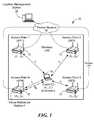
- FIG. 1is a block diagram of an exemplary client position location system using a location management station and constructed in accordance with the principles of the present invention
- FIG. 2is a is a block diagram of an exemplary client position location system using self localization and constructed in accordance with the principles of the present invention
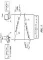
- FIG. 3is a graphical representation of a two-way ranging protocol used in accordance with the principles of the present invention.
- FIG. 4is a graphical representation of an alternate ranging protocol used in accordance with the principles of the present invention.
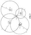
- FIG. 5illustrates the use of trilateration as a client positioning technique used in accordance with the principles of the present invention
- FIG. 6illustrates the use of virtual reference stations as a client positioning technique
- FIG. 7illustrates the technique of trilateration and radical lines in determining the client position
- FIG. 8illustrates the intersection of two circles and the formation of a radical line
- FIG. 9illustrates examples of where two circles do not intersect to form a radical line and where trilateration methods would not be effective
- FIG. 10is a graphical representation illustrating the intersection of two lines as representing the client location
- FIG. 11illustrates three point collinearity where trilateration would also not be effective.
- FIG. 12illustrates examples of intersecting circle and radical line scenarios.
- relational termssuch as “first” and “second,” “top” and “bottom,” and the like, may be used solely to distinguish one entity or element from another entity or element without necessarily requiring or implying any physical or logical relationship or order between such entities or elements.
- One embodiment of the present inventionadvantageously provides a method and system for indoor position location of clients in wireless local area networks (“WLANs”).
- the position location method of the present inventionutilizes the time-of-flight (“TOF”) measurements of signals transmitted from a client to a number of wireless access points (“APs”) or vice versa to determine distances.
- TOFtime-of-flight
- APswireless access points
- RTTRound-trip time
- ranging protocolsalso called “ranging protocols”
- NLOSnon-line-of sight
- trilateration methodsare utilized in combination with median filtering of measurements to accurately estimate the position of the client.
- the inventionprovides the concept of Virtual Reference Stations (“VRSs”), whereby at any given instance of applying trilateration there is an AP in the WLAN that assumes the role of a temporary reference station and is not involved in the trilateration process.
- Trilaterationuses a minimum of three APs to compute the location of the client on a two-dimensional plane.
- VRSs together with trilateration and median filteringallow for the mitigation of the undesirable effects of indoor NLOS errors on the accuracy of the of the ranging protocol and TOF estimation between the client and the APs
- the present inventionprovides a WLAN location technique based on distance computations provided by TOF measurements. These measurements are, in turn, obtained from RTT ranging protocol measurements between the client, whose location is to be determined, and the WLAN APs.
- the inventionis divided into two subsystems, one being a ranging subsystem, and the other being a positioning subsystem.
- the ranging subsystemestimates the distance between the client and the APs, and the positioning subsystem calculates the client's position using the distances already estimated and the APs' known positions.
- TOF measurementsrequire precise knowledge of the signal transmission start time at the sender and time of arrival (“TOA”) at the receiver.
- TOAtime of arrival
- the present inventionadvantageously incorporates the concept of a Virtual Reference Station (“VRS”).
- VRSVirtual Reference Station
- a VRSis an AP in the WLAN that assumes the role of a temporary reference station and is not involved in the trilateration process.
- VRSis used together with trilateration and median filtering of measurements to determine the position of the client. This technique allows for the minimization of the TOF estimation error due to multipath signals.
- the inventionprovides the ability to identify and remove NLOS errors before measurements are used in the position computations.
- the proposed NLOS mitigation methoddepends on system redundancy or high client-AP hearability (i.e., high number of APs) such that the greater the number of APs deployed in the system, the higher the number of NLOS errors that can be detected and mitigated.
- the methodassumes that the number of distance measurements or equivalently, number of APs, is greater than the minimum number required for trilateration, which is three, for client location in a two-dimensional plane. This serves to provide the necessary system redundancy such that the present invention is capable of mitigating the NLOS errors in location estimation even when the distance (or range) measurements corrupted by NLOS errors are not directly identifiable.
- FIG. 1a location system constructed in accordance with the principles of the present invention and designated generally as “ 10 ”.
- System 10is a network with access points (“APs”) 12 and a client 14 at an unknown position.
- APs 12are devices that allow for wireless devices to communicate with each other by acting as both a transmitter and receiver of WLAN radio signals.
- APs 12are dedicated hardware devices that include a built-in network adapter, antenna, and radio transmitter.
- there are at least three APs 12(AP 1 through AP 4 ), that receive signals from a client 14 that is at an unknown location. It is assumed that APs 12 are preferably placed in a non-collinear fashion and the location of the APs 12 are known (as depicted in FIGS. 1 and 2 ).
- FIG. 1illustrates an exemplary embodiment where a location management station (“LMS”) 16 is in electronic communication with the APs 12 over a packet network 18 and where LMS 16 calculates the location of client.
- the LMS 16includes an interface module that receives signals from each AP 12 representing the AP's estimated distance to client 14 and a processor that calculates the location of client 14 based on the received estimated distances from each AP 12 to client 14 and the known position of each AP 12 .
- LMS 16also includes the necessary hardware and software to allow it to transmit and receive signals representing the location of client 12 to and from outside entities upon request.
- Each AP 12each listens to signals from client 14 in order to generate a time of flight (“TOF”) between the AP 12 and the client 14 .
- TOFtime of flight
- the TOFis then used to generate a set of distances between the APs 12 and client 14 .
- Each AP 12then forwards its distance measurement for a particular client 12 to a LMS 16 over network 18 .
- LMS 16performs a method stored in its memory in order to determine the actual location of client 14 .
- LMS 16retrieves measurement data from each of the APs 12 , where all measurements from the APs 12 are sent to LMS 16 for further processing and analysis. LMS 16 also calculates mobile positions from the measurement data by using measurements from APs 12 and their known locations. The LMS 16 then calculates the position of client. 14 . LMS 16 also administers and controls location system 10 .
- the LMS 16sends the client's position to gateway mobile location centers for distribution to applications/servers for location-based mobile services.
- LMS 16also manages communications between the location system 10 and external entities such as gateway mobile location centers and network operations centers.
- LMS 16In addition to calculating mobile positions, LMS 16 also manages, coordinates, and administers the location system 10 and provides interfaces to external entities such as network operations and administration centers/systems.
- a location activityis initiated by an application external to the location system 10 itself
- a gateway mobile location centerin response to an application's request for a location, screens the request and forwards it through the network to LMS 16 .
- LMS 16sends the calculated client's position information through a gateway mobile location center to an external entity, typically the application that initiated the location activity or, in the case of public safety locations, to the appropriate emergency service center/public safety answering point.
- TOFuses the absolute time it takes for a signal to travel from client 14 to an AP 12 .
- An AP 12uses the TOF to calculate the distance between the client 14 and the AP 12 .
- Signalstravel with a known velocity (i.e., speed of light), so the distance can be directly calculated from the TOF and the velocity of the signal.
- TOF measurementsrequire accurate time synchronization to accurately measure TOF. Time synchronization is required both at the APs 12 and the client 14 .
- Nodes that run ranging protocolstypically function by exchanging request (“RQ”) and response (“RP”) messages, computing round-trip time using multiple timestamps, estimating one-way time delay (TOF) and converting into distance assuming path symmetry, and minimizing end-system software stack effects on ranging by using hardware timestamping.
- RQrequest
- RPresponse
- TOFtime delay
- end-system software stack effects on ranging by using hardware timestampingIf timestamping is performed in the application layer, interrupts and other unpredictable software processes can introduce jitter and latency which in turn may impair the ranging accuracy. Even the use of precise external oscillators would not overcome the stack jitter associated with a software-only implementation.
- Most applicationsrequire the higher accuracy achieved by timestamping packets at the interface between the physical (“PHY”) and data link (“MAC”) layers (often referred to as “hardware timestamping”).
- FIG. 3illustrates one embodiment where a two-way ranging protocol is used.
- This protocolforms the basis for ranging in the Network Time Protocol (“NTP”) and IEEE 1588 Precision Time Protocol (“PTP”).
- NTPNetwork Time Protocol
- PTPPrecision Time Protocol
- the underlying assumption of these protocolsis that both forward and reverse paths of the client-server communication are symmetric and have a fixed communication delay.
- AP 12initially sends a request message 20 to client 14 that contains the timestamp T i1 that the message is sent.
- Client 14notes the time it receives this message as T i2 and, at a later time, sends a response message 22 back to AP 12 containing the time T i1 , which is the time AP 12 sent the request message 20 , the time T i2 which is the time client 14 received message 20 , and the time T i3 that represents the time the client 14 sends the response message 22 .
- the AP 12notes the time it receives message 22 as T i4 .
- T i2T i1 ⁇ i + ⁇ t i
- T i4T i3 + ⁇ i + ⁇ t i
- the clock offset ⁇ ican be used to remove any missynchronization in the case of unsynchronized devices.
- Another exemplary ranging protocol that is used with the location system 10 of the present inventionis an IEEE 802.1AS ranging protocol.
- This protocolillustrated in FIG. 4 , is particularly suited for wireless environment such as the IEEE 802.11 because it has request, acknowledgment, and follow-up messages to handle the media contention behavior of such protocols which often lead to collisions and packet losses.
- an AP 12schedules a request message (Pdelay_Req) 24 for transmission.
- Pdelay_Reqrequest message
- timestamp T i1is captured using the AP clock.
- Timestamp T i2is also captured in the PHY as the message 24 is being received at the client 14 .
- the client MAC protocolresponds with an acknowledgment message (Pdelay_Resp) 26 to the AP at time T i3 .
- the arrival time of message 26is captured by the AP 12 as T i4 .
- a follow-up message (Pdelay_Resp_Follow_Up) 28is then sent by the client 14 to the AP 12 carrying the timestamps ⁇ T i2 ,T i3 ⁇ captured by the client 14 .
- the AP 12uses the timestamps obtained, the AP 12 calculates the fixed delay ⁇ t i as shown above in the discussion relating to FIG. 3 .
- Trilaterationuses the known locations of three or more APs 12 , and the measured distance between the client 14 and each AP 12 to determine the relative location of the client 14 .
- the client's location on a two-dimensional planecan be computed as the intersection of three circles as can be seen in FIG. 5 .
- the area of client position uncertaintyis relatively small if there are no NLOS errors. In other words, the intersection of circles is concentrated near the true client location, as shown in FIG. 5 . In contrast, the area of uncertainty is large if any AP 12 suffers from NLOS errors.
- the TOF measurements related to this AP 12will have a bias equal to the NLOS error and the associated circles will move away from the true client location. Consequently, the intersections between these shifted circles and other circles will also move away from the true MS location, enlarging the area of uncertainty.
- FIG. 6illustrates the use of a Virtual Reference Station (“VRS”) in location system 10 of the present invention.
- a VRSis an AP in the WLAN that assumes the role of a temporary reference station and is not involved in the client location process.
- a grouping of N APs 12 in a WLAN systemis shown in FIG. 6 .
- each AP 12performs a distance measurement to client 14 .
- the distance measurement performed by AP i, which is located at (x i y i )is represented by r i . Since a minimum of three AP measurements are needed for trilateration (as shown by the dashed lines), L subsets of measurements are created, each of which contains three distances:
- Subsets that cannot be used in the trilaterationare excluded leaving M subsets.
- One aspect of the location technique of the present inventionis the use of virtual reference stations (“VRSs”) as shown FIGS. 1 , 2 and 6 .
- VRSsvirtual reference stations
- Nthere are (N ⁇ 3) VRSs.
- SLEsquare-of-location-error
- the sources of errorscan be categorized as systematic, such as those related to mis-synchronization between transmitter and receiver, and channel-related, such as those due to NLOS channel conditions.
- systematic errors in the distance measurementstend to be smaller making the dominant source of errors to be channel-related.
- NLOS channel conditionsgenerally result in the strongest signal being received with longer delay, with the resulting distance measurement being longer than it should be.
- P client(x l , y l ) can be found that minimizes the median of the SLE computations.
- the distance measurementscan be group into subsets, each subset with its associated VRSs, and intermediate location estimates and SLEs derived for these subsets. Some of the intermediate estimates would have lower SLEs than others.
- the present inventionrequires no statistical models or prior information on the LOS-NLOS channel conditions.
- a line 30 joining the two intersecting points of the two circlescan be used to accurately locate the client 14 .
- the radical line 30also called the “radical axis”, is the locus of points of equal circle power with respect to two non-concentric circles 32 and 34 .
- radical line 30is perpendicular to the line of centers. If the circles have radii r 1 and r 2 , then their centers are separated by a distance d. If the circles intersect in two points, then the radical line 30 is the line passing through the points of intersection.
- P 3(x 3 , y 3 ) as shown in FIG. 8 .
- x 3x 2 ⁇ h ⁇ ( y 1 - y 0 ) d
- y 3y 2 ⁇ h ⁇ ( x 1 - x 0 ) d which can also be expressed as:
- the location system 10 of the present inventionutilizes the concept of the point of intersection of two lines in order to pin-point the location of client 14 .
- the followingdescribes an exemplary method that determines the point of intersection of two lines.
- P 2(x 2 , y 2 ) are the two points on
- u a( x 4 - x 3 ) ⁇ ( y 1 - y 3 ) - ( y 4 - y 3 ) ⁇ ( x 1 - x 3 ) ( y 4 - y 3 ) ⁇ ( x 2 - x 1 ) - ( x 4 - x 3 ) ⁇ ( y 2 - y 1 )
- u b( x 2 - x 1 ) ⁇ ( y 1 - y 3 ) - ( y 2 - y 1 ) ⁇ ( x 1 - x 3 ) ( y 4 - y 3 ) ⁇ ( x 2 - x 1 ) - ( x 4 - x 3 ) ⁇ ( y 2 - y 1 ) From FIG.
- xx 1 +u a ( x 2 ⁇ x 1 )
- yy 1 +u a ( y 2 ⁇ y 1 )
- xx 3 +u b ( x 4 ⁇ x 3 )
- yy 3 +u b ( y 4 ⁇ y 3 )
- intersections of two circlesdetermines a line known as the radical line. If three circles mutually intersect in a single point, their point of intersection is the intersection of their pairwise radical lines, known as the radical center.
- the trilateration algorithmthat is used with the present invention can now be described. As shown above, the intersection point of the radical lines, each of which interconnects the intersection points of a pair of intersecting loci, gives the location of client 14 .
- the trilateration process of the present inventionis now described.
- the initial step in the trilateration processis to determine the TOF between AP i and the client, ⁇ t i .
- u a( x 4 - x 3 ) ⁇ ( y 1 - y 3 ) - ( y 4 - y 3 ) ⁇ ( x 1 - x 3 ) ( y 4 - y 3 ) ⁇ ( x 2 - x 1 ) - ( x 4 - x 3 ) ⁇ ( y 2 - y 1 ) ; (x 1 ,y 1 ) and (x 2 ,y 2 ) are the two points of one line and (x 3 ,y 3 ) and (x 4 ,y 4 ) are the two points of the other line.
- a more tractable conditionis obtained by noting that the area of a triangle determined by three points will be zero if and only if they are collinear. This includes the degenerate cases of two or all three points being concurrent), i.e.,
- Median filteringis a non-linear digital filtering technique used to remove noise from images or other signals. It is useful in the removal of impulse noise from signals.
- the techniqueexamines a sample of the input and decides if it is representative of the signal. This is performed using a window consisting of an odd number of samples. The values in the window are sorted into numerical order; the median value, the sample in the center of the window, is selected as the output. The oldest sample is discarded, a new sample acquired, and the calculation repeats.
- image processingit is usually necessary to perform high degree of noise reduction in an image before performing higher-level processing steps, such as edge detection.
- the number of APsis greater than the minimum required for trilateration (three). Particularly, with a high system redundancy, only a small number of measurements are likely to contain NLOS errors. Then, using trilateration, a number of clean intersections will exist near the true client position.
- the distance measurementscan be group into subsets, each subset with its associated VRSs, and intermediate location estimates and SLEs derived for these subsets. Median filtering of the resulting SLEs removes aberrant data points or large impulse noise values (subsets with very large NLOS errors) while preserving mostly “clean” data point (subsets without NLOS errors).
- the median filteris a suitable mechanism for removing or ignoring the effects of inappropriate data points.
- the accuracy of the location algorithm of the present inventiondepends on system redundancy, that is, the larger the number of APs, the higher the client-AP hearability and positioning accuracy.
- the hearability improvement through the deployment of a larger number of APsallows for the client to receive signals from a greater number of APs thereby achieving a larger number or redundant trilateration instances and VRSs.
- the benefits of having higher positioning accuracyout-weigh the costs of having system redundancy since the costs of APs are low and their prices continue to fall.
- the intermediate client location P c (x c , y c )can be correctly estimated when there are multiple clean intersections. As a result, multiple clean intersections can provide dominant intersection possibilities near the true client location. Therefore, NLOS-error mitigation capability can be achieved by the number of clean intersections and the total number of intersections. The more APs 12 used, the greater the number of intersection possibilities and, therefore, the higher the positioning accuracy. NLOS errors cannot be mitigated if the number of APs 12 is less than or equal to four because of the lack of redundancy, i.e., a minimum of three APs 12 are required for trilateration. With four APs 12 , there is one VRS and three APs 12 participating in trilateration.
- the next step in the algorithmexcludes subsets, if any, that cannot be used in the trilateration, leaving M subsets.
- the distance and the square-of-location-error (SLE)are computed as follows:
- each intermediate estimate p k,c(x k,c ,y k,c ) is weighted by the inverse of its associated MedS, MedS k .
- the final estimateis then computed by the following normalized linear equation:
- the location method of the present inventionthus includes of two primary components.
- the intermediate client locationis derived from TOF measurements using the ranging protocols.
- the second componentis the identification and mitigation of NLOS errors in order to improve positioning accuracy using the median filtering of squares of location errors (SLE).
- SLEmedian filtering of squares of location errors
- the present inventioncan be realized in hardware, software, or a combination of hardware and software. Any kind of computing system, or other apparatus adapted for carrying out the methods described herein, is suited to perform the functions described herein.
- a typical combination of hardware and softwarecould be a specialized or general purpose computer system having one or more processing elements and a computer program stored on a storage medium that, when loaded and executed, controls the computer system such that it carries out the methods described herein.
- the present inventioncan also be embedded in a computer program product, which comprises all the features enabling the implementation of the methods described herein, and which, when loaded in a computing system is able to carry out these methods.
- Storage mediumrefers to any volatile or non-volatile storage device.
- Computer program or application in the present contextmeans any expression, in any language, code or notation, of a set of instructions intended to cause a system having an information processing capability to perform a particular function either directly or after either or both of the following a) conversion to another language, code or notation; b) reproduction in a different material form.
Landscapes
- Engineering & Computer Science (AREA)
- Radar, Positioning & Navigation (AREA)
- Remote Sensing (AREA)
- Physics & Mathematics (AREA)
- General Physics & Mathematics (AREA)
- Computer Networks & Wireless Communication (AREA)
- Mobile Radio Communication Systems (AREA)
- Position Fixing By Use Of Radio Waves (AREA)
Abstract
Description
Ti2=Ti1−θi+Δti
Ti4=Ti3+θi+Δti
From these equations, the
The clock offset θican be used to remove any missynchronization in the case of unsynchronized devices.
is the distance between the client intermediate location Pc=(xc,yc) and a VRS j at (xj,yj), j=1, 2, . . . , (N−3). The SLE is considered a residual of the intermediate location estimate. When ideal conditions exist and there are no measurement errors and
a2+h2=r02
b2+h2=r12
Noting from
from which it is seen that a=r0, that is, a reduces to r0when the two circles touch at one point, i.e., d=r0+r1. Alternatively, knowing the points P0=(x0, y0) and P1=(x1, y1), d can be obtained as
Substituting a into the first equation, h can be derived by
from which two intersection points of two non-concentric circles are derived as:
which can also be expressed as:
- 1. if r0+r1<d, then the circles are separate, resulting in no intersection (as shown in
FIG. 9 ) - 2. if
- 1. if r0+r1<d, then the circles are separate, resulting in no intersection (as shown in
- then the circles just touch each other (as shown in
FIG. 9 ). - 3. if |r0−r1|>d, then one circle is contained within the other, also resulting in no intersection (as shown in
FIG. 9 ). - 4. if
- then the circles just touch each other (as shown in
- then the circles intersect (as shown in
FIG. 8 ).Circles satisfying conditions 1 to 3 above are not used in the trilateration. The present invention contemplates the use of circlessatisfying condition 4 above.
- then the circles intersect (as shown in
Pa=P1+ua(P2−P1)
Pb=P3+ub(P4−P3)
By setting Pa=Pb=P, the following two equations with the two unknowns uaand ubcan be derived:
x1+ua(x2−x1)=x3+ub(x4−x3)
y1+ua(y2−y1)=y3+ub(y4−y3)
where P1=(x1, y1)=P and P2=(x2, y2) are the two points on line a, and P3=(x3, y3) and P4=(x4, y4) are the two points on line b. These two equations are solved to obtain the following expressions for uaand ub:
From
x=x1+ua(x2−x1)
y=y1+ua(y2−y1)
or
x=x3+ub(x4−x3)
y=y3+ub(y4−y3)
Thus, by substituting either uaor ub, into the above, the point P=(x, y), can be identified.
For each pair of intersecting circles, ciand cj, i≠j, (where ciis the locus of circle around APi), the radical line, lij, must then be determined (two pairs of circles are sufficient). The two intersection points of two non-concentric circles are given by:
x31=x2+h(y1−y0)/d
x32=x2−h(y1−y0)/d
and
y31=y2−h(x1−x0)/d
y32=y2+h(x1−x0)/d
where P0=(x0, y0) is the center of one circle with radius r0; P1=(x1, y1) is the center of the other circle with radius r1; P2=(x2, y2)=P0+a(P1−P0)/d; d2=(x1−x0)2+(y1−y0)2;
and a=(r02−r12+d2)/(2d). For each pair of radical lines, lijand ljk, i≠j≠k, the point of intersection must then be determined. The intersection point of
two radical lines is given by:
x=x1+ua(x2−x1)
y=y1+ua(y2−y1)
where
(x1,y1) and (x2,y2) are the two points of one line and (x3,y3) and (x4,y4) are the two points of the other line. The point of intersection determined by the above steps is the position of the client Pc=(xc, yc).
or, in expanded form,
x1(y2−y3)+x2(y3−y1)+x3(y1−y2)=0. The condition for three points to be collinear can also be expressed as the statement that the distance between any one point and the line determined by the other two is zero. The above properties can be used to eliminate circles with collinear centers when performing the trilateration.
A1x+B1y+C1=0
A2x+B2y+C2=0
A3x+B3y+C3=0
in Cartesian coordinates are concurrent if their coefficients satisfy
This property can be used in the location algorithm of the present invention as a further test in ensuring that the radical lines do intersect when determining the location of
MedSk=Median[SLEk,j], j=1,2, . . . , (N−3)
- k=1, 2, . . . , M
Claims (16)
SLEj=∥gj−rj∥2, j=1,2, . . . , (N−3)
gj=√{square root over ((xc−xj)2+(yc−yj)2)}{square root over ((xc−xj)2+(yc−yj)2)},
Priority Applications (3)
| Application Number | Priority Date | Filing Date | Title |
|---|---|---|---|
| US12/336,671US8165150B2 (en) | 2008-12-17 | 2008-12-17 | Method and system for wireless LAN-based indoor position location |
| PCT/CA2009/001841WO2010069061A1 (en) | 2008-12-17 | 2009-12-17 | Method and system for wireless lan-based indoor position location |
| US13/431,423US8737279B1 (en) | 2008-12-17 | 2012-03-27 | Method and system for wireless LAN-based indoor position location |
Applications Claiming Priority (1)
| Application Number | Priority Date | Filing Date | Title |
|---|---|---|---|
| US12/336,671US8165150B2 (en) | 2008-12-17 | 2008-12-17 | Method and system for wireless LAN-based indoor position location |
Related Child Applications (1)
| Application Number | Title | Priority Date | Filing Date |
|---|---|---|---|
| US13/431,423ContinuationUS8737279B1 (en) | 2008-12-17 | 2012-03-27 | Method and system for wireless LAN-based indoor position location |
Publications (2)
| Publication Number | Publication Date |
|---|---|
| US20100150117A1 US20100150117A1 (en) | 2010-06-17 |
| US8165150B2true US8165150B2 (en) | 2012-04-24 |
Family
ID=42240434
Family Applications (2)
| Application Number | Title | Priority Date | Filing Date |
|---|---|---|---|
| US12/336,671Active2030-10-15US8165150B2 (en) | 2008-12-17 | 2008-12-17 | Method and system for wireless LAN-based indoor position location |
| US13/431,423Active2029-03-07US8737279B1 (en) | 2008-12-17 | 2012-03-27 | Method and system for wireless LAN-based indoor position location |
Family Applications After (1)
| Application Number | Title | Priority Date | Filing Date |
|---|---|---|---|
| US13/431,423Active2029-03-07US8737279B1 (en) | 2008-12-17 | 2012-03-27 | Method and system for wireless LAN-based indoor position location |
Country Status (2)
| Country | Link |
|---|---|
| US (2) | US8165150B2 (en) |
| WO (1) | WO2010069061A1 (en) |
Cited By (19)
| Publication number | Priority date | Publication date | Assignee | Title |
|---|---|---|---|---|
| US20100130229A1 (en)* | 2008-11-21 | 2010-05-27 | Qualcomm Incorporated | Wireless-based positioning adjustments using a motion sensor |
| US20100128617A1 (en)* | 2008-11-25 | 2010-05-27 | Qualcomm Incorporated | Method and apparatus for two-way ranging |
| US20100130230A1 (en)* | 2008-11-21 | 2010-05-27 | Qualcomm Incorporated | Beacon sectoring for position determination |
| US20100128637A1 (en)* | 2008-11-21 | 2010-05-27 | Qualcomm Incorporated | Network-centric determination of node processing delay |
| US20100135178A1 (en)* | 2008-11-21 | 2010-06-03 | Qualcomm Incorporated | Wireless position determination using adjusted round trip time measurements |
| US20100159958A1 (en)* | 2008-12-22 | 2010-06-24 | Qualcomm Incorporated | Post-deployment calibration for wireless position determination |
| US20100172259A1 (en)* | 2009-01-05 | 2010-07-08 | Qualcomm Incorporated | Detection Of Falsified Wireless Access Points |
| US20110269478A1 (en)* | 2010-04-30 | 2011-11-03 | Qualcomm Incorporated | Device for round trip time measurements |
| US8737279B1 (en)* | 2008-12-17 | 2014-05-27 | Avaya Inc. | Method and system for wireless LAN-based indoor position location |
| US20140213290A1 (en)* | 2011-10-31 | 2014-07-31 | Panasonic Corporation | Position estimation device, position estimation method, program and integrated circuit |
| US8933776B2 (en) | 2012-07-20 | 2015-01-13 | Qualcomm Incorporated | Relative positioning applications in wireless devices |
| US8990014B2 (en) | 2013-03-15 | 2015-03-24 | Trx Systems, Inc. | Method to scale inertial location data using directional and/or scale confidence constraints |
| US9241252B2 (en) | 2013-12-20 | 2016-01-19 | Google Inc. | Identifying an entity associated with wireless network access point |
| US9288635B2 (en) | 2012-10-18 | 2016-03-15 | Electronics And Telecommunications Research Institute | Apparatus for managing indoor moving object based on indoor map and positioning infrastructure and method thereof |
| US9907047B1 (en) | 2016-08-30 | 2018-02-27 | Qualcomm Incorporated | Passive positioning procedure and use of single burst ASAP FTM sessions |
| US10039073B2 (en) | 2013-01-03 | 2018-07-31 | Qualcomm Incorporated | Method for determining location of wireless devices |
| US10182413B2 (en) | 2014-07-30 | 2019-01-15 | Qualcomm Incorporated | Wireless positioning using scheduled transmissions |
| US10849205B2 (en) | 2015-10-14 | 2020-11-24 | Current Lighting Solutions, Llc | Luminaire having a beacon and a directional antenna |
| US11356932B2 (en) | 2014-06-30 | 2022-06-07 | Hewlett Packard Enterprise Development Lp | Channel scan based on mobility state |
Families Citing this family (101)
| Publication number | Priority date | Publication date | Assignee | Title |
|---|---|---|---|---|
| US8184038B2 (en)* | 2008-08-20 | 2012-05-22 | Qualcomm Incorporated | Two-way ranging with inter-pulse transmission and reception |
| US8290508B2 (en)* | 2009-07-23 | 2012-10-16 | Broadcom Corporation | Estimating a subscriber location |
| KR20110101403A (en)* | 2010-03-08 | 2011-09-16 | 삼성전자주식회사 | Packet forwarding apparatus and method of base station in wireless communication system |
| US8422986B1 (en)* | 2010-06-03 | 2013-04-16 | 8X8, Inc. | Systems, methods, devices and arrangements for emergency call services using non-traditional endpoint devices |
| US9116223B1 (en) | 2010-06-03 | 2015-08-25 | 8X8, Inc. | Systems, methods, devices and arrangements for emergency call services and user participation incentives |
| US9689988B1 (en) | 2010-06-03 | 2017-06-27 | 8X8, Inc. | Systems, methods, devices and arrangements for emergency call services and emergency broadcasts |
| US8879540B1 (en) | 2010-06-03 | 2014-11-04 | 8X8, Inc. | Systems, methods, devices and arrangements for emergency call services |
| US9606219B2 (en) | 2010-08-02 | 2017-03-28 | Progeny Systems Corporation | Systems and methods for locating a target in a GPS-denied environment |
| KR20120034338A (en)* | 2010-10-01 | 2012-04-12 | 삼성전자주식회사 | Security operating method for access point and system thereof |
| CN102456170A (en)* | 2010-10-19 | 2012-05-16 | 上海万康无线智能控制系统有限公司 | Indoor personnel positioning management system |
| US20120120874A1 (en)* | 2010-11-15 | 2012-05-17 | Decawave Limited | Wireless access point clock synchronization system |
| US8743782B1 (en)* | 2010-11-18 | 2014-06-03 | Cellco Partnership | Automated method to determine position of Wi-Fi access point to enable location based services |
| US8823510B2 (en) | 2010-12-23 | 2014-09-02 | Klindown, Llc | Systems and methods for wirelessly programming a prescription bottle cap |
| US8448873B2 (en) | 2010-12-23 | 2013-05-28 | Klindown, Llc | Systems and methods for parsing prescription information for a wirelessly programmable prescription bottle cap |
| US8547870B2 (en) | 2011-06-07 | 2013-10-01 | Qualcomm Incorporated | Hybrid positioning mechanism for wireless communication devices |
| US8509809B2 (en) | 2011-06-10 | 2013-08-13 | Qualcomm Incorporated | Third party device location estimation in wireless communication networks |
| US8909244B2 (en) | 2011-06-28 | 2014-12-09 | Qualcomm Incorporated | Distributed positioning mechanism for wireless communication devices |
| US8489114B2 (en) | 2011-09-19 | 2013-07-16 | Qualcomm Incorporated | Time difference of arrival based positioning system |
| US8521181B2 (en) | 2011-09-19 | 2013-08-27 | Qualcomm Incorporated | Time of arrival based positioning system |
| US8457655B2 (en) | 2011-09-19 | 2013-06-04 | Qualcomm Incorporated | Hybrid time of arrival based positioning system |
| US8675561B2 (en)* | 2011-09-21 | 2014-03-18 | Qualcomm Incorporated | WiFi distance measurement using location packets |
| CN103024091B (en)* | 2011-09-26 | 2016-05-25 | 阿里巴巴集团控股有限公司 | Obtain method and the device of networking client actual physical address |
| US8755304B2 (en)* | 2011-10-21 | 2014-06-17 | Qualcomm Incorporated | Time of arrival based positioning for wireless communication systems |
| CN106353723B (en)* | 2011-11-04 | 2019-12-13 | 瑞典爱立信有限公司 | Positioning of user equipment based on virtual reference measurements |
| US8787191B2 (en)* | 2011-11-15 | 2014-07-22 | Qualcomm Incorporated | Method and apparatus for determining distance in a Wi-Fi network |
| US8824325B2 (en) | 2011-12-08 | 2014-09-02 | Qualcomm Incorporated | Positioning technique for wireless communication system |
| CN103188791B (en) | 2011-12-28 | 2016-07-13 | 华为终端有限公司 | A kind of localization method, client and alignment system |
| US9282471B2 (en) | 2012-03-21 | 2016-03-08 | Digimarc Corporation | Positioning systems for wireless networks |
| US9953303B2 (en)* | 2012-04-25 | 2018-04-24 | ZR Investments, LLC | Time tracking device and method |
| CN103379437A (en) | 2012-04-28 | 2013-10-30 | 华为终端有限公司 | Wireless terminal positioning method, related device and related system |
| KR20140005451A (en)* | 2012-07-04 | 2014-01-15 | 한국전자통신연구원 | Method and apparatus for estimating position of terminal using generation of virtual infrastructure |
| CN102802259A (en)* | 2012-07-26 | 2012-11-28 | 中国科学院计算技术研究所 | Directional Wi-Fi (Wireless Fidelity)-based wireless positioning system and method |
| US20140077998A1 (en)* | 2012-09-17 | 2014-03-20 | Yuval Amizur | Supplemental location-related information transmit in unassociated wireless states |
| US20140126394A1 (en)* | 2012-11-08 | 2014-05-08 | Adrian P. Stephens | ADAPTIVE OPTIMIZATION OF TIME OF FLIGHT (ToF) EXCHANGE |
| WO2014099030A1 (en) | 2012-12-18 | 2014-06-26 | Intel Corporation | Wireless station and methods for tof positioning using reverse-direction grant |
| US9432882B2 (en) | 2013-01-29 | 2016-08-30 | Qualcomm Incorporated | System and method for deploying an RTT-based indoor positioning system |
| EP2959309B1 (en) | 2013-02-19 | 2019-05-15 | Intel IP Corporation | Improved wireless network location techniques |
| US20140333482A1 (en)* | 2013-05-10 | 2014-11-13 | Telcom Ventures, Llc | Methods of position-location determination using a high-confidence range, and related systems and devices |
| WO2014193477A1 (en)* | 2013-05-28 | 2014-12-04 | Intel Corporation | Time-of-flight location determination with unmanaged wlan |
| US10609762B2 (en) | 2013-06-06 | 2020-03-31 | Zebra Technologies Corporation | Method, apparatus, and computer program product improving backhaul of sensor and other data to real time location system network |
| US9517417B2 (en) | 2013-06-06 | 2016-12-13 | Zih Corp. | Method, apparatus, and computer program product for performance analytics determining participant statistical data and game status data |
| US20140365194A1 (en) | 2013-06-06 | 2014-12-11 | Zih Corp. | Method, apparatus, and computer program product for dynamics/kinetics model selection |
| US9715005B2 (en) | 2013-06-06 | 2017-07-25 | Zih Corp. | Method, apparatus, and computer program product improving real time location systems with multiple location technologies |
| US11423464B2 (en) | 2013-06-06 | 2022-08-23 | Zebra Technologies Corporation | Method, apparatus, and computer program product for enhancement of fan experience based on location data |
| US9699278B2 (en) | 2013-06-06 | 2017-07-04 | Zih Corp. | Modular location tag for a real time location system network |
| US10437658B2 (en) | 2013-06-06 | 2019-10-08 | Zebra Technologies Corporation | Method, apparatus, and computer program product for collecting and displaying sporting event data based on real time data for proximity and movement of objects |
| WO2015030816A1 (en)* | 2013-08-30 | 2015-03-05 | Hewlett-Packard Development Company, L.P. | Localization using time-of-flight |
| WO2015038176A1 (en)* | 2013-09-13 | 2015-03-19 | Intel Corporation | Time of flight window limit synchronization |
| WO2015047234A1 (en)* | 2013-09-25 | 2015-04-02 | Intel Corporation | Authenticated time-of-flight indoor positioning systems and methods |
| CN105531599A (en)* | 2013-10-17 | 2016-04-27 | 英特尔公司 | Method and apparatus for time of flight fingerprint and geo-location |
| WO2015060884A1 (en)* | 2013-10-25 | 2015-04-30 | Intel Corporation | Secure wireless location interface protocol |
| CN105829909B (en)* | 2013-10-25 | 2019-06-11 | 英特尔公司 | Wireless Indoor Positioning Air Interface Protocol |
| CN103716879B (en)* | 2013-12-26 | 2017-07-04 | 北京交通大学 | Using the wireless location new method of geometric distance under NLOS environment |
| US20150264530A1 (en)* | 2014-03-12 | 2015-09-17 | Gaby Prechner | Access point initiated time-of-flight positioning |
| CN106461754B (en) | 2014-06-05 | 2019-10-11 | 斑马技术公司 | For the receiver processor determined with high-resolution TOA that adaptively opens a window |
| US9661455B2 (en) | 2014-06-05 | 2017-05-23 | Zih Corp. | Method, apparatus, and computer program product for real time location system referencing in physically and radio frequency challenged environments |
| US20150375083A1 (en) | 2014-06-05 | 2015-12-31 | Zih Corp. | Method, Apparatus, And Computer Program Product For Enhancement Of Event Visualizations Based On Location Data |
| US9668164B2 (en) | 2014-06-05 | 2017-05-30 | Zih Corp. | Receiver processor for bandwidth management of a multiple receiver real-time location system (RTLS) |
| US10261169B2 (en) | 2014-06-05 | 2019-04-16 | Zebra Technologies Corporation | Method for iterative target location in a multiple receiver target location system |
| US9626616B2 (en) | 2014-06-05 | 2017-04-18 | Zih Corp. | Low-profile real-time location system tag |
| CA2951154C (en) | 2014-06-05 | 2019-08-13 | Zih Corp. | Systems, apparatus and methods for variable rate ultra-wideband communications |
| EP3152585B1 (en) | 2014-06-06 | 2022-04-27 | Zebra Technologies Corporation | Method, apparatus, and computer program product improving real time location systems with multiple location technologies |
| US9759803B2 (en) | 2014-06-06 | 2017-09-12 | Zih Corp. | Method, apparatus, and computer program product for employing a spatial association model in a real time location system |
| DE102014214823A1 (en)* | 2014-07-29 | 2016-02-04 | Bayerische Motoren Werke Aktiengesellschaft | Determination of a delay |
| CN104185273A (en)* | 2014-08-26 | 2014-12-03 | 中国科学院电子学研究所 | Anchor-node-free positioning method, system and device for distance measuring |
| CN104301868A (en)* | 2014-10-10 | 2015-01-21 | 西北工业大学 | High-precision indoor positioning method based on frame round-trip and time-of-arrival ranging technology |
| WO2016076893A1 (en)* | 2014-11-14 | 2016-05-19 | Hewlett Packard Enterprise Development Lp | Determining a location of a device |
| US9877300B2 (en) | 2014-11-24 | 2018-01-23 | Hewlett Packard Enterprise Development Lp | Determining a location of a disconnected device |
| KR102415859B1 (en) | 2014-12-12 | 2022-07-04 | 삼성전자주식회사 | Method for estimating location, electronic apparatus and server |
| US9578504B2 (en)* | 2014-12-12 | 2017-02-21 | Intel Corporation | Authentication and authorization in a wearable ensemble |
| EP3237811B1 (en) | 2014-12-22 | 2021-01-27 | Trane International Inc. | Occupancy sensing and building control using mobile devices |
| US9485609B2 (en)* | 2015-02-06 | 2016-11-01 | Nxp B.V. | Pulse frequency control for wireless communications and ranging |
| HK1244147A1 (en)* | 2015-02-06 | 2018-07-27 | 苹果公司 | Positioning with wlan time of flight |
| US9672125B2 (en)* | 2015-04-10 | 2017-06-06 | Pure Storage, Inc. | Ability to partition an array into two or more logical arrays with independently running software |
| US10775749B2 (en) | 2015-04-17 | 2020-09-15 | The Mitre Corporation | Robust and resilient timing architecture for critical infrastructure |
| CN104822135A (en)* | 2015-05-13 | 2015-08-05 | 北京交通大学 | Cellular network wireless cooperation location method suitable to be used in NLOS environment |
| US9907042B2 (en)* | 2015-06-15 | 2018-02-27 | Intel IP Corporation | Apparatus, system and method of determining a time synchronization function (TSF) based on fine time measurement (FTM) messages |
| US9763046B2 (en) | 2015-08-27 | 2017-09-12 | Intel IP Corporation | Apparatus, system and method of Fine Timing Measurement (FTM) |
| US10009430B2 (en) | 2015-08-27 | 2018-06-26 | Intel IP Corporation | Apparatus, system and method of fine timing measurement (FTM) |
| JP6510988B2 (en)* | 2016-01-20 | 2019-05-08 | 日本電信電話株式会社 | Positioning system and positioning method |
| WO2017162810A1 (en)* | 2016-03-25 | 2017-09-28 | Tarkett Gdl | In-floor distributed antenna and positioning system |
| US10530934B1 (en) | 2016-05-04 | 2020-01-07 | 8X8, Inc. | Endpoint location determination for call routing decisions |
| US11076051B1 (en) | 2016-05-04 | 2021-07-27 | 8X8, Inc. | Endpoint location update control for call routing decisions |
| US10542150B1 (en) | 2016-05-04 | 2020-01-21 | 8X8, Inc. | Server generated timing of location updates for call routing decisions |
| US10326888B1 (en) | 2016-05-04 | 2019-06-18 | 8X8, Inc. | Location updates for call routing decisions |
| CN107708065B (en)* | 2016-08-08 | 2020-08-14 | 华为技术有限公司 | A positioning system, method and device |
| US11271838B2 (en)* | 2017-01-13 | 2022-03-08 | International Business Machines Corporation | Timing synchronization |
| CN106931973A (en)* | 2017-03-14 | 2017-07-07 | 杭州电子科技大学 | High accuracy indoor locating system and method based on nonlinear FM pulse signal |
| DE102017210895A1 (en)* | 2017-06-28 | 2019-01-03 | Bayerische Motoren Werke Aktiengesellschaft | A method, computer readable medium, system, and vehicle comprising the system for validating a time function of a master and the clients in a network of a vehicle |
| US10575275B2 (en)* | 2017-08-23 | 2020-02-25 | Locix, Inc. | Systems and methods for adaptively selecting distance estimates for localization of nodes based on error metric information |
| CN111819466B (en)* | 2018-03-29 | 2024-10-18 | 索尼公司 | Apparatus, system and method for locating objects in a scene |
| CN111989587B (en) | 2018-04-19 | 2024-04-12 | 亚萨合莱有限公司 | Determining a location of a mobile device |
| CN108924756B (en)* | 2018-06-30 | 2020-08-18 | 天津大学 | Indoor positioning method based on WiFi dual-band |
| WO2020044192A1 (en) | 2018-08-26 | 2020-03-05 | Celeno Communications (Israel) Ltd. | Wi-fi radar detection using synchronized wireless access point |
| EP3906426B1 (en) | 2018-12-31 | 2025-04-02 | Celeno Communications (Israel) Ltd. | Coherent wi-fi radar using wireless access point |
| US11102750B2 (en) | 2019-01-01 | 2021-08-24 | Celeno Communications (Israel) Ltd. | Positioning system based on distributed transmission and reception of Wi-Fi signals |
| US12192947B2 (en)* | 2019-02-19 | 2025-01-07 | Qualcomm Incorporated | Systems and methods for positioning with channel measurements |
| CN110658492A (en)* | 2019-10-10 | 2020-01-07 | 重庆邮电大学 | An Iterative Method for Position Optimization of Indoor Targets and Scatterers |
| CN111487586B (en)* | 2020-04-22 | 2023-06-02 | 中国民航大学 | Method for Improving Positioning Accuracy Based on Distributed Passive Positioning Technology |
| CN114609586B (en)* | 2022-03-23 | 2025-03-21 | 中国科学院计算技术研究所 | A one-way ranging positioning method based on wireless signal arrival time |
| WO2023193884A1 (en)* | 2022-04-05 | 2023-10-12 | Nokia Technologies Oy | Positioning in a mobile communication system |
Citations (11)
| Publication number | Priority date | Publication date | Assignee | Title |
|---|---|---|---|---|
| US20040131032A1 (en)* | 2002-08-30 | 2004-07-08 | Andrew Sendonaris | Communication system performance using position location information |
| US6826162B2 (en) | 2001-09-28 | 2004-11-30 | Hewlett-Packard Development Company, L.P. | Locating and mapping wireless network devices via wireless gateways |
| US20040258012A1 (en)* | 2003-05-23 | 2004-12-23 | Nec Corporation | Location sensing system and method using packets asynchronously transmitted between wireless stations |
| US6865484B2 (en)* | 2001-04-11 | 2005-03-08 | Mitsui & Co., Ltd. | Satellite position measurement system |
| US7085588B1 (en) | 2004-05-27 | 2006-08-01 | Autocell Laboratories, Inc. | System and method for determining and representing one or more potential physical locations of a newly detected wireless network device |
| US7116988B2 (en) | 2004-03-16 | 2006-10-03 | Airespace, Inc. | Location of wireless nodes using signal strength weighting metric |
| US7205938B2 (en) | 2004-03-05 | 2007-04-17 | Airespace, Inc. | Wireless node location mechanism responsive to observed propagation characteristics of wireless network infrastructure signals |
| US7313403B2 (en) | 2003-08-06 | 2007-12-25 | Hong Kong Applied Science And Technology Research Institute Co., Ltd. | Location positioning in wireless networks |
| US7567822B2 (en)* | 2005-10-11 | 2009-07-28 | Cisco Technology, Inc. | Automated configuration of RF WLANs via selected sensors |
| US20100020776A1 (en)* | 2007-11-27 | 2010-01-28 | Google Inc. | Wireless network-based location approximation |
| US7877101B1 (en)* | 2006-12-28 | 2011-01-25 | Marvell International Ltd. | Locating a WLAN station using signal propagation delay |
Family Cites Families (3)
| Publication number | Priority date | Publication date | Assignee | Title |
|---|---|---|---|---|
| US7499423B1 (en)* | 2004-06-10 | 2009-03-03 | Cisco Technology, Inc. (Us) | System and method for clock distribution and synchronization and radio location |
| US7907579B2 (en)* | 2006-08-15 | 2011-03-15 | Cisco Technology, Inc. | WiFi geolocation from carrier-managed system geolocation of a dual mode device |
| US8165150B2 (en)* | 2008-12-17 | 2012-04-24 | Avaya Inc. | Method and system for wireless LAN-based indoor position location |
- 2008
- 2008-12-17USUS12/336,671patent/US8165150B2/enactiveActive
- 2009
- 2009-12-17WOPCT/CA2009/001841patent/WO2010069061A1/enactiveApplication Filing
- 2012
- 2012-03-27USUS13/431,423patent/US8737279B1/enactiveActive
Patent Citations (11)
| Publication number | Priority date | Publication date | Assignee | Title |
|---|---|---|---|---|
| US6865484B2 (en)* | 2001-04-11 | 2005-03-08 | Mitsui & Co., Ltd. | Satellite position measurement system |
| US6826162B2 (en) | 2001-09-28 | 2004-11-30 | Hewlett-Packard Development Company, L.P. | Locating and mapping wireless network devices via wireless gateways |
| US20040131032A1 (en)* | 2002-08-30 | 2004-07-08 | Andrew Sendonaris | Communication system performance using position location information |
| US20040258012A1 (en)* | 2003-05-23 | 2004-12-23 | Nec Corporation | Location sensing system and method using packets asynchronously transmitted between wireless stations |
| US7313403B2 (en) | 2003-08-06 | 2007-12-25 | Hong Kong Applied Science And Technology Research Institute Co., Ltd. | Location positioning in wireless networks |
| US7205938B2 (en) | 2004-03-05 | 2007-04-17 | Airespace, Inc. | Wireless node location mechanism responsive to observed propagation characteristics of wireless network infrastructure signals |
| US7116988B2 (en) | 2004-03-16 | 2006-10-03 | Airespace, Inc. | Location of wireless nodes using signal strength weighting metric |
| US7085588B1 (en) | 2004-05-27 | 2006-08-01 | Autocell Laboratories, Inc. | System and method for determining and representing one or more potential physical locations of a newly detected wireless network device |
| US7567822B2 (en)* | 2005-10-11 | 2009-07-28 | Cisco Technology, Inc. | Automated configuration of RF WLANs via selected sensors |
| US7877101B1 (en)* | 2006-12-28 | 2011-01-25 | Marvell International Ltd. | Locating a WLAN station using signal propagation delay |
| US20100020776A1 (en)* | 2007-11-27 | 2010-01-28 | Google Inc. | Wireless network-based location approximation |
Non-Patent Citations (1)
| Title |
|---|
| International Search Report and Written Opinion dated Mar. 25, 2010 for International Application No. PCT/CA2009/001841, International Filing Date: Dec. 17, 2009 consisting of 10-pages. |
Cited By (35)
| Publication number | Priority date | Publication date | Assignee | Title |
|---|---|---|---|---|
| US8892127B2 (en) | 2008-11-21 | 2014-11-18 | Qualcomm Incorporated | Wireless-based positioning adjustments using a motion sensor |
| US20100130230A1 (en)* | 2008-11-21 | 2010-05-27 | Qualcomm Incorporated | Beacon sectoring for position determination |
| US20100128637A1 (en)* | 2008-11-21 | 2010-05-27 | Qualcomm Incorporated | Network-centric determination of node processing delay |
| US20100135178A1 (en)* | 2008-11-21 | 2010-06-03 | Qualcomm Incorporated | Wireless position determination using adjusted round trip time measurements |
| US9645225B2 (en) | 2008-11-21 | 2017-05-09 | Qualcomm Incorporated | Network-centric determination of node processing delay |
| US9291704B2 (en) | 2008-11-21 | 2016-03-22 | Qualcomm Incorporated | Wireless-based positioning adjustments using a motion sensor |
| US9213082B2 (en) | 2008-11-21 | 2015-12-15 | Qualcomm Incorporated | Processing time determination for wireless position determination |
| US20100130229A1 (en)* | 2008-11-21 | 2010-05-27 | Qualcomm Incorporated | Wireless-based positioning adjustments using a motion sensor |
| US20100128617A1 (en)* | 2008-11-25 | 2010-05-27 | Qualcomm Incorporated | Method and apparatus for two-way ranging |
| US9125153B2 (en) | 2008-11-25 | 2015-09-01 | Qualcomm Incorporated | Method and apparatus for two-way ranging |
| US8737279B1 (en)* | 2008-12-17 | 2014-05-27 | Avaya Inc. | Method and system for wireless LAN-based indoor position location |
| US9002349B2 (en) | 2008-12-22 | 2015-04-07 | Qualcomm Incorporated | Post-deployment calibration for wireless position determination |
| US8831594B2 (en) | 2008-12-22 | 2014-09-09 | Qualcomm Incorporated | Post-deployment calibration of wireless base stations for wireless position determination |
| US8768344B2 (en) | 2008-12-22 | 2014-07-01 | Qualcomm Incorporated | Post-deployment calibration for wireless position determination |
| US20100159958A1 (en)* | 2008-12-22 | 2010-06-24 | Qualcomm Incorporated | Post-deployment calibration for wireless position determination |
| US20100172259A1 (en)* | 2009-01-05 | 2010-07-08 | Qualcomm Incorporated | Detection Of Falsified Wireless Access Points |
| US8750267B2 (en) | 2009-01-05 | 2014-06-10 | Qualcomm Incorporated | Detection of falsified wireless access points |
| US9137681B2 (en) | 2010-04-30 | 2015-09-15 | Qualcomm Incorporated | Device for round trip time measurements |
| US20110269478A1 (en)* | 2010-04-30 | 2011-11-03 | Qualcomm Incorporated | Device for round trip time measurements |
| US9247446B2 (en)* | 2010-04-30 | 2016-01-26 | Qualcomm Incorporated | Mobile station use of round trip time measurements |
| US8781492B2 (en)* | 2010-04-30 | 2014-07-15 | Qualcomm Incorporated | Device for round trip time measurements |
| US20140213290A1 (en)* | 2011-10-31 | 2014-07-31 | Panasonic Corporation | Position estimation device, position estimation method, program and integrated circuit |
| US9372254B2 (en)* | 2011-10-31 | 2016-06-21 | Panasonic Intellectual Property Corporation Of America | Position estimation device, position estimation method, program and integrated circuit |
| US8933776B2 (en) | 2012-07-20 | 2015-01-13 | Qualcomm Incorporated | Relative positioning applications in wireless devices |
| US9288635B2 (en) | 2012-10-18 | 2016-03-15 | Electronics And Telecommunications Research Institute | Apparatus for managing indoor moving object based on indoor map and positioning infrastructure and method thereof |
| US10039073B2 (en) | 2013-01-03 | 2018-07-31 | Qualcomm Incorporated | Method for determining location of wireless devices |
| US10219241B2 (en) | 2013-01-03 | 2019-02-26 | Csr Technology Inc. | Method for determining location of wireless devices |
| US10624055B2 (en) | 2013-01-03 | 2020-04-14 | Csr Technology Inc. | Method for determining location of wireless devices |
| US8990014B2 (en) | 2013-03-15 | 2015-03-24 | Trx Systems, Inc. | Method to scale inertial location data using directional and/or scale confidence constraints |
| US9241252B2 (en) | 2013-12-20 | 2016-01-19 | Google Inc. | Identifying an entity associated with wireless network access point |
| US9794766B2 (en) | 2013-12-20 | 2017-10-17 | Google Inc. | Identifying an entity associated with wireless network access point |
| US11356932B2 (en) | 2014-06-30 | 2022-06-07 | Hewlett Packard Enterprise Development Lp | Channel scan based on mobility state |
| US10182413B2 (en) | 2014-07-30 | 2019-01-15 | Qualcomm Incorporated | Wireless positioning using scheduled transmissions |
| US10849205B2 (en) | 2015-10-14 | 2020-11-24 | Current Lighting Solutions, Llc | Luminaire having a beacon and a directional antenna |
| US9907047B1 (en) | 2016-08-30 | 2018-02-27 | Qualcomm Incorporated | Passive positioning procedure and use of single burst ASAP FTM sessions |
Also Published As
| Publication number | Publication date |
|---|---|
| US20100150117A1 (en) | 2010-06-17 |
| WO2010069061A1 (en) | 2010-06-24 |
| US8737279B1 (en) | 2014-05-27 |
Similar Documents
| Publication | Publication Date | Title |
|---|---|---|
| US8165150B2 (en) | Method and system for wireless LAN-based indoor position location | |
| US12375881B2 (en) | Method and system for radiolocation asset tracking via a mesh network | |
| Muthukrishnan et al. | Towards smart surroundings: Enabling techniques and technologies for localization | |
| EP1506686B1 (en) | Improved position determination in wireless communication systems | |
| US7616965B2 (en) | Method and apparatus for calculating a device location | |
| Correal et al. | An UWB relative location system | |
| JP5775449B2 (en) | Method and system for determining position using a hybrid satellite / WLAN positioning system by selecting the best WLAN-PS derived solution | |
| US9494432B2 (en) | Collaborative navigation techniques for mobile devices | |
| US6885969B2 (en) | Location estimation in partially synchronized networks | |
| US8081923B1 (en) | Method and apparatus for providing location services for a distributed network | |
| EP2674775A1 (en) | Wireless localisation system | |
| US20080194226A1 (en) | Method and Apparatus for Providing Location Services for a Distributed Network | |
| US10495737B1 (en) | Methods, systems, and computer readable media for time-slotted ultra-wide-band object tracking | |
| JP2018529084A (en) | Extended passive positioning with adaptive active positioning | |
| US10356741B2 (en) | Fingerprint positioning for mobile terminals | |
| JP4860901B2 (en) | Method and apparatus for synchronizing base stations using mobile GPS stations | |
| KR20140086321A (en) | Method and apparatus for tracking position using ad hoc network and mobile telecommunication system for the same | |
| US20180088205A1 (en) | Positioning | |
| Bouras et al. | Time difference of arrival localization study for SAR systems over LoRaWAN | |
| Bouras et al. | Geolocation analysis for search and rescue systems using LoRaWAN | |
| KR102332561B1 (en) | Method for reconizing ble based a position using rssi compensation and appartus for supporting the same | |
| JP5215440B2 (en) | Method and apparatus for synchronizing base stations using mobile GPS stations | |
| Cho et al. | Performance tests for wireless real-time localization systems to improve mobile robot navigation in various indoor environments | |
| Guo et al. | On the accuracy of an indoor location-sensing technique suitable for impulse radio networks | |
| Maghdid | Hybridisation of GNSS with other wireless/sensors technologies onboard smartphones to offer seamless outdoors-indoors positioning for LBS applications |
Legal Events
| Date | Code | Title | Description |
|---|---|---|---|
| AS | Assignment | Owner name:NORTEL NETWORKS LIMITED,CANADA Free format text:ASSIGNMENT OF ASSIGNORS INTEREST;ASSIGNORS:AWEYA, JAMES;BARBOSA, LUIS OROZCO;SIGNING DATES FROM 20081209 TO 20081211;REEL/FRAME:021991/0913 Owner name:UNIVERSITY OF CASTILLA-LA MANCHA,SPAIN Free format text:ASSIGNMENT OF ASSIGNORS INTEREST;ASSIGNORS:AWEYA, JAMES;BARBOSA, LUIS OROZCO;SIGNING DATES FROM 20081209 TO 20081211;REEL/FRAME:021991/0913 Owner name:NORTEL NETWORKS LIMITED, CANADA Free format text:ASSIGNMENT OF ASSIGNORS INTEREST;ASSIGNORS:AWEYA, JAMES;BARBOSA, LUIS OROZCO;SIGNING DATES FROM 20081209 TO 20081211;REEL/FRAME:021991/0913 Owner name:UNIVERSITY OF CASTILLA-LA MANCHA, SPAIN Free format text:ASSIGNMENT OF ASSIGNORS INTEREST;ASSIGNORS:AWEYA, JAMES;BARBOSA, LUIS OROZCO;SIGNING DATES FROM 20081209 TO 20081211;REEL/FRAME:021991/0913 | |
| AS | Assignment | Owner name:CITIBANK, N.A., AS ADMINISTRATIVE AGENT,NEW YORK Free format text:SECURITY AGREEMENT;ASSIGNOR:AVAYA INC.;REEL/FRAME:023892/0500 Effective date:20100129 Owner name:CITIBANK, N.A., AS ADMINISTRATIVE AGENT, NEW YORK Free format text:SECURITY AGREEMENT;ASSIGNOR:AVAYA INC.;REEL/FRAME:023892/0500 Effective date:20100129 | |
| AS | Assignment | Owner name:CITICORP USA, INC., AS ADMINISTRATIVE AGENT, NEW YORK Free format text:SECURITY AGREEMENT;ASSIGNOR:AVAYA INC.;REEL/FRAME:023905/0001 Effective date:20100129 Owner name:CITICORP USA, INC., AS ADMINISTRATIVE AGENT,NEW YO Free format text:SECURITY AGREEMENT;ASSIGNOR:AVAYA INC.;REEL/FRAME:023905/0001 Effective date:20100129 Owner name:CITICORP USA, INC., AS ADMINISTRATIVE AGENT, NEW Y Free format text:SECURITY AGREEMENT;ASSIGNOR:AVAYA INC.;REEL/FRAME:023905/0001 Effective date:20100129 | |
| AS | Assignment | Owner name:AVAYA INC.,NEW JERSEY Free format text:ASSIGNMENT OF ASSIGNORS INTEREST;ASSIGNOR:NORTEL NETWORKS LIMITED;REEL/FRAME:023998/0878 Effective date:20091218 Owner name:AVAYA INC., NEW JERSEY Free format text:ASSIGNMENT OF ASSIGNORS INTEREST;ASSIGNOR:NORTEL NETWORKS LIMITED;REEL/FRAME:023998/0878 Effective date:20091218 | |
| AS | Assignment | Owner name:BANK OF NEW YORK MELLON TRUST, NA, AS NOTES COLLAT Free format text:SECURITY AGREEMENT;ASSIGNOR:AVAYA INC., A DELAWARE CORPORATION;REEL/FRAME:025863/0535 Effective date:20110211 Owner name:BANK OF NEW YORK MELLON TRUST, NA, AS NOTES COLLATERAL AGENT, THE, PENNSYLVANIA Free format text:SECURITY AGREEMENT;ASSIGNOR:AVAYA INC., A DELAWARE CORPORATION;REEL/FRAME:025863/0535 Effective date:20110211 | |
| FEPP | Fee payment procedure | Free format text:PAYOR NUMBER ASSIGNED (ORIGINAL EVENT CODE: ASPN); ENTITY STATUS OF PATENT OWNER: LARGE ENTITY | |
| STCF | Information on status: patent grant | Free format text:PATENTED CASE | |
| CC | Certificate of correction | ||
| AS | Assignment | Owner name:BANK OF NEW YORK MELLON TRUST COMPANY, N.A., THE, PENNSYLVANIA Free format text:SECURITY AGREEMENT;ASSIGNOR:AVAYA, INC.;REEL/FRAME:030083/0639 Effective date:20130307 Owner name:BANK OF NEW YORK MELLON TRUST COMPANY, N.A., THE, Free format text:SECURITY AGREEMENT;ASSIGNOR:AVAYA, INC.;REEL/FRAME:030083/0639 Effective date:20130307 | |
| FPAY | Fee payment | Year of fee payment:4 | |
| AS | Assignment | Owner name:CITIBANK, N.A., AS ADMINISTRATIVE AGENT, NEW YORK Free format text:SECURITY INTEREST;ASSIGNORS:AVAYA INC.;AVAYA INTEGRATED CABINET SOLUTIONS INC.;OCTEL COMMUNICATIONS CORPORATION;AND OTHERS;REEL/FRAME:041576/0001 Effective date:20170124 | |
| AS | Assignment | Owner name:OCTEL COMMUNICATIONS LLC (FORMERLY KNOWN AS OCTEL COMMUNICATIONS CORPORATION), CALIFORNIA Free format text:BANKRUPTCY COURT ORDER RELEASING ALL LIENS INCLUDING THE SECURITY INTEREST RECORDED AT REEL/FRAME 041576/0001;ASSIGNOR:CITIBANK, N.A.;REEL/FRAME:044893/0531 Effective date:20171128 Owner name:AVAYA INTEGRATED CABINET SOLUTIONS INC., CALIFORNIA Free format text:BANKRUPTCY COURT ORDER RELEASING ALL LIENS INCLUDING THE SECURITY INTEREST RECORDED AT REEL/FRAME 041576/0001;ASSIGNOR:CITIBANK, N.A.;REEL/FRAME:044893/0531 Effective date:20171128 Owner name:AVAYA INC., CALIFORNIA Free format text:BANKRUPTCY COURT ORDER RELEASING ALL LIENS INCLUDING THE SECURITY INTEREST RECORDED AT REEL/FRAME 025863/0535;ASSIGNOR:THE BANK OF NEW YORK MELLON TRUST, NA;REEL/FRAME:044892/0001 Effective date:20171128 Owner name:AVAYA INC., CALIFORNIA Free format text:BANKRUPTCY COURT ORDER RELEASING ALL LIENS INCLUDING THE SECURITY INTEREST RECORDED AT REEL/FRAME 023892/0500;ASSIGNOR:CITIBANK, N.A.;REEL/FRAME:044891/0564 Effective date:20171128 Owner name:AVAYA INC., CALIFORNIA Free format text:BANKRUPTCY COURT ORDER RELEASING ALL LIENS INCLUDING THE SECURITY INTEREST RECORDED AT REEL/FRAME 041576/0001;ASSIGNOR:CITIBANK, N.A.;REEL/FRAME:044893/0531 Effective date:20171128 Owner name:AVAYA INTEGRATED CABINET SOLUTIONS INC., CALIFORNI Free format text:BANKRUPTCY COURT ORDER RELEASING ALL LIENS INCLUDING THE SECURITY INTEREST RECORDED AT REEL/FRAME 041576/0001;ASSIGNOR:CITIBANK, N.A.;REEL/FRAME:044893/0531 Effective date:20171128 Owner name:VPNET TECHNOLOGIES, INC., CALIFORNIA Free format text:BANKRUPTCY COURT ORDER RELEASING ALL LIENS INCLUDING THE SECURITY INTEREST RECORDED AT REEL/FRAME 041576/0001;ASSIGNOR:CITIBANK, N.A.;REEL/FRAME:044893/0531 Effective date:20171128 Owner name:OCTEL COMMUNICATIONS LLC (FORMERLY KNOWN AS OCTEL Free format text:BANKRUPTCY COURT ORDER RELEASING ALL LIENS INCLUDING THE SECURITY INTEREST RECORDED AT REEL/FRAME 041576/0001;ASSIGNOR:CITIBANK, N.A.;REEL/FRAME:044893/0531 Effective date:20171128 Owner name:AVAYA INC., CALIFORNIA Free format text:BANKRUPTCY COURT ORDER RELEASING ALL LIENS INCLUDING THE SECURITY INTEREST RECORDED AT REEL/FRAME 030083/0639;ASSIGNOR:THE BANK OF NEW YORK MELLON TRUST COMPANY, N.A.;REEL/FRAME:045012/0666 Effective date:20171128 | |
| AS | Assignment | Owner name:GOLDMAN SACHS BANK USA, AS COLLATERAL AGENT, NEW YORK Free format text:SECURITY INTEREST;ASSIGNORS:AVAYA INC.;AVAYA INTEGRATED CABINET SOLUTIONS LLC;OCTEL COMMUNICATIONS LLC;AND OTHERS;REEL/FRAME:045034/0001 Effective date:20171215 Owner name:GOLDMAN SACHS BANK USA, AS COLLATERAL AGENT, NEW Y Free format text:SECURITY INTEREST;ASSIGNORS:AVAYA INC.;AVAYA INTEGRATED CABINET SOLUTIONS LLC;OCTEL COMMUNICATIONS LLC;AND OTHERS;REEL/FRAME:045034/0001 Effective date:20171215 | |
| AS | Assignment | Owner name:SIERRA HOLDINGS CORP., NEW JERSEY Free format text:RELEASE BY SECURED PARTY;ASSIGNOR:CITICORP USA, INC.;REEL/FRAME:045045/0564 Effective date:20171215 Owner name:AVAYA, INC., CALIFORNIA Free format text:RELEASE BY SECURED PARTY;ASSIGNOR:CITICORP USA, INC.;REEL/FRAME:045045/0564 Effective date:20171215 | |
| AS | Assignment | Owner name:CITIBANK, N.A., AS COLLATERAL AGENT, NEW YORK Free format text:SECURITY INTEREST;ASSIGNORS:AVAYA INC.;AVAYA INTEGRATED CABINET SOLUTIONS LLC;OCTEL COMMUNICATIONS LLC;AND OTHERS;REEL/FRAME:045124/0026 Effective date:20171215 | |
| MAFP | Maintenance fee payment | Free format text:PAYMENT OF MAINTENANCE FEE, 8TH YEAR, LARGE ENTITY (ORIGINAL EVENT CODE: M1552); ENTITY STATUS OF PATENT OWNER: LARGE ENTITY Year of fee payment:8 | |
| AS | Assignment | Owner name:WILMINGTON TRUST, NATIONAL ASSOCIATION, MINNESOTA Free format text:SECURITY INTEREST;ASSIGNORS:AVAYA INC.;AVAYA MANAGEMENT L.P.;INTELLISIST, INC.;AND OTHERS;REEL/FRAME:053955/0436 Effective date:20200925 | |
| AS | Assignment | Owner name:WILMINGTON TRUST, NATIONAL ASSOCIATION, AS COLLATERAL AGENT, DELAWARE Free format text:INTELLECTUAL PROPERTY SECURITY AGREEMENT;ASSIGNORS:AVAYA INC.;INTELLISIST, INC.;AVAYA MANAGEMENT L.P.;AND OTHERS;REEL/FRAME:061087/0386 Effective date:20220712 | |
| AS | Assignment | Owner name:AVAYA INTEGRATED CABINET SOLUTIONS LLC, NEW JERSEY Free format text:RELEASE OF SECURITY INTEREST IN PATENTS AT REEL 45124/FRAME 0026;ASSIGNOR:CITIBANK, N.A., AS COLLATERAL AGENT;REEL/FRAME:063457/0001 Effective date:20230403 Owner name:AVAYA MANAGEMENT L.P., NEW JERSEY Free format text:RELEASE OF SECURITY INTEREST IN PATENTS AT REEL 45124/FRAME 0026;ASSIGNOR:CITIBANK, N.A., AS COLLATERAL AGENT;REEL/FRAME:063457/0001 Effective date:20230403 Owner name:AVAYA INC., NEW JERSEY Free format text:RELEASE OF SECURITY INTEREST IN PATENTS AT REEL 45124/FRAME 0026;ASSIGNOR:CITIBANK, N.A., AS COLLATERAL AGENT;REEL/FRAME:063457/0001 Effective date:20230403 Owner name:AVAYA HOLDINGS CORP., NEW JERSEY Free format text:RELEASE OF SECURITY INTEREST IN PATENTS AT REEL 45124/FRAME 0026;ASSIGNOR:CITIBANK, N.A., AS COLLATERAL AGENT;REEL/FRAME:063457/0001 Effective date:20230403 | |
| AS | Assignment | Owner name:WILMINGTON SAVINGS FUND SOCIETY, FSB (COLLATERAL AGENT), DELAWARE Free format text:INTELLECTUAL PROPERTY SECURITY AGREEMENT;ASSIGNORS:AVAYA MANAGEMENT L.P.;AVAYA INC.;INTELLISIST, INC.;AND OTHERS;REEL/FRAME:063742/0001 Effective date:20230501 | |
| AS | Assignment | Owner name:CITIBANK, N.A., AS COLLATERAL AGENT, NEW YORK Free format text:INTELLECTUAL PROPERTY SECURITY AGREEMENT;ASSIGNORS:AVAYA INC.;AVAYA MANAGEMENT L.P.;INTELLISIST, INC.;REEL/FRAME:063542/0662 Effective date:20230501 | |
| AS | Assignment | Owner name:AVAYA MANAGEMENT L.P., NEW JERSEY Free format text:RELEASE OF SECURITY INTEREST IN PATENTS (REEL/FRAME 045034/0001);ASSIGNOR:GOLDMAN SACHS BANK USA., AS COLLATERAL AGENT;REEL/FRAME:063779/0622 Effective date:20230501 Owner name:CAAS TECHNOLOGIES, LLC, NEW JERSEY Free format text:RELEASE OF SECURITY INTEREST IN PATENTS (REEL/FRAME 045034/0001);ASSIGNOR:GOLDMAN SACHS BANK USA., AS COLLATERAL AGENT;REEL/FRAME:063779/0622 Effective date:20230501 Owner name:HYPERQUALITY II, LLC, NEW JERSEY Free format text:RELEASE OF SECURITY INTEREST IN PATENTS (REEL/FRAME 045034/0001);ASSIGNOR:GOLDMAN SACHS BANK USA., AS COLLATERAL AGENT;REEL/FRAME:063779/0622 Effective date:20230501 Owner name:HYPERQUALITY, INC., NEW JERSEY Free format text:RELEASE OF SECURITY INTEREST IN PATENTS (REEL/FRAME 045034/0001);ASSIGNOR:GOLDMAN SACHS BANK USA., AS COLLATERAL AGENT;REEL/FRAME:063779/0622 Effective date:20230501 Owner name:ZANG, INC. (FORMER NAME OF AVAYA CLOUD INC.), NEW JERSEY Free format text:RELEASE OF SECURITY INTEREST IN PATENTS (REEL/FRAME 045034/0001);ASSIGNOR:GOLDMAN SACHS BANK USA., AS COLLATERAL AGENT;REEL/FRAME:063779/0622 Effective date:20230501 Owner name:VPNET TECHNOLOGIES, INC., NEW JERSEY Free format text:RELEASE OF SECURITY INTEREST IN PATENTS (REEL/FRAME 045034/0001);ASSIGNOR:GOLDMAN SACHS BANK USA., AS COLLATERAL AGENT;REEL/FRAME:063779/0622 Effective date:20230501 Owner name:OCTEL COMMUNICATIONS LLC, NEW JERSEY Free format text:RELEASE OF SECURITY INTEREST IN PATENTS (REEL/FRAME 045034/0001);ASSIGNOR:GOLDMAN SACHS BANK USA., AS COLLATERAL AGENT;REEL/FRAME:063779/0622 Effective date:20230501 Owner name:AVAYA INTEGRATED CABINET SOLUTIONS LLC, NEW JERSEY Free format text:RELEASE OF SECURITY INTEREST IN PATENTS (REEL/FRAME 045034/0001);ASSIGNOR:GOLDMAN SACHS BANK USA., AS COLLATERAL AGENT;REEL/FRAME:063779/0622 Effective date:20230501 Owner name:INTELLISIST, INC., NEW JERSEY Free format text:RELEASE OF SECURITY INTEREST IN PATENTS (REEL/FRAME 045034/0001);ASSIGNOR:GOLDMAN SACHS BANK USA., AS COLLATERAL AGENT;REEL/FRAME:063779/0622 Effective date:20230501 Owner name:AVAYA INC., NEW JERSEY Free format text:RELEASE OF SECURITY INTEREST IN PATENTS (REEL/FRAME 045034/0001);ASSIGNOR:GOLDMAN SACHS BANK USA., AS COLLATERAL AGENT;REEL/FRAME:063779/0622 Effective date:20230501 Owner name:AVAYA INTEGRATED CABINET SOLUTIONS LLC, NEW JERSEY Free format text:RELEASE OF SECURITY INTEREST IN PATENTS (REEL/FRAME 53955/0436);ASSIGNOR:WILMINGTON TRUST, NATIONAL ASSOCIATION, AS NOTES COLLATERAL AGENT;REEL/FRAME:063705/0023 Effective date:20230501 Owner name:INTELLISIST, INC., NEW JERSEY Free format text:RELEASE OF SECURITY INTEREST IN PATENTS (REEL/FRAME 53955/0436);ASSIGNOR:WILMINGTON TRUST, NATIONAL ASSOCIATION, AS NOTES COLLATERAL AGENT;REEL/FRAME:063705/0023 Effective date:20230501 Owner name:AVAYA INC., NEW JERSEY Free format text:RELEASE OF SECURITY INTEREST IN PATENTS (REEL/FRAME 53955/0436);ASSIGNOR:WILMINGTON TRUST, NATIONAL ASSOCIATION, AS NOTES COLLATERAL AGENT;REEL/FRAME:063705/0023 Effective date:20230501 Owner name:AVAYA MANAGEMENT L.P., NEW JERSEY Free format text:RELEASE OF SECURITY INTEREST IN PATENTS (REEL/FRAME 53955/0436);ASSIGNOR:WILMINGTON TRUST, NATIONAL ASSOCIATION, AS NOTES COLLATERAL AGENT;REEL/FRAME:063705/0023 Effective date:20230501 Owner name:AVAYA INTEGRATED CABINET SOLUTIONS LLC, NEW JERSEY Free format text:RELEASE OF SECURITY INTEREST IN PATENTS (REEL/FRAME 61087/0386);ASSIGNOR:WILMINGTON TRUST, NATIONAL ASSOCIATION, AS NOTES COLLATERAL AGENT;REEL/FRAME:063690/0359 Effective date:20230501 Owner name:INTELLISIST, INC., NEW JERSEY Free format text:RELEASE OF SECURITY INTEREST IN PATENTS (REEL/FRAME 61087/0386);ASSIGNOR:WILMINGTON TRUST, NATIONAL ASSOCIATION, AS NOTES COLLATERAL AGENT;REEL/FRAME:063690/0359 Effective date:20230501 Owner name:AVAYA INC., NEW JERSEY Free format text:RELEASE OF SECURITY INTEREST IN PATENTS (REEL/FRAME 61087/0386);ASSIGNOR:WILMINGTON TRUST, NATIONAL ASSOCIATION, AS NOTES COLLATERAL AGENT;REEL/FRAME:063690/0359 Effective date:20230501 Owner name:AVAYA MANAGEMENT L.P., NEW JERSEY Free format text:RELEASE OF SECURITY INTEREST IN PATENTS (REEL/FRAME 61087/0386);ASSIGNOR:WILMINGTON TRUST, NATIONAL ASSOCIATION, AS NOTES COLLATERAL AGENT;REEL/FRAME:063690/0359 Effective date:20230501 | |
| AS | Assignment | Owner name:AVAYA LLC, DELAWARE Free format text:(SECURITY INTEREST) GRANTOR'S NAME CHANGE;ASSIGNOR:AVAYA INC.;REEL/FRAME:065019/0231 Effective date:20230501 | |
| MAFP | Maintenance fee payment | Free format text:PAYMENT OF MAINTENANCE FEE, 12TH YEAR, LARGE ENTITY (ORIGINAL EVENT CODE: M1553); ENTITY STATUS OF PATENT OWNER: LARGE ENTITY Year of fee payment:12 |