US8165114B2 - Voice over IP capturing - Google Patents
Voice over IP capturingDownload PDFInfo
- Publication number
- US8165114B2 US8165114B2US11/452,917US45291706AUS8165114B2US 8165114 B2US8165114 B2US 8165114B2US 45291706 AUS45291706 AUS 45291706AUS 8165114 B2US8165114 B2US 8165114B2
- Authority
- US
- United States
- Prior art keywords
- voip
- data packets
- forwarding
- data packet
- network
- Prior art date
- Legal status (The legal status is an assumption and is not a legal conclusion. Google has not performed a legal analysis and makes no representation as to the accuracy of the status listed.)
- Active, expires
Links
- 238000010079rubber tappingMethods0.000claimsabstractdescription33
- 238000000034methodMethods0.000claimsdescription28
- 238000004891communicationMethods0.000claimsdescription19
- 230000010354integrationEffects0.000claimsdescription4
- 238000001514detection methodMethods0.000claims1
- 238000010586diagramMethods0.000description28
- 230000008520organizationEffects0.000description10
- 230000007246mechanismEffects0.000description8
- 238000012544monitoring processMethods0.000description8
- 238000005516engineering processMethods0.000description7
- 230000002093peripheral effectEffects0.000description5
- 238000009826distributionMethods0.000description4
- 230000005540biological transmissionEffects0.000description3
- 238000012986modificationMethods0.000description2
- 230000004048modificationEffects0.000description2
- 230000008569processEffects0.000description2
- 238000010276constructionMethods0.000description1
- 238000007781pre-processingMethods0.000description1
- 238000012545processingMethods0.000description1
- 238000012797qualificationMethods0.000description1
- 238000012857repackingMethods0.000description1
- 238000004904shorteningMethods0.000description1
- 238000009827uniform distributionMethods0.000description1
Images


Classifications
- H—ELECTRICITY
- H04—ELECTRIC COMMUNICATION TECHNIQUE
- H04L—TRANSMISSION OF DIGITAL INFORMATION, e.g. TELEGRAPHIC COMMUNICATION
- H04L12/00—Data switching networks
- H04L12/66—Arrangements for connecting between networks having differing types of switching systems, e.g. gateways
- H—ELECTRICITY
- H04—ELECTRIC COMMUNICATION TECHNIQUE
- H04L—TRANSMISSION OF DIGITAL INFORMATION, e.g. TELEGRAPHIC COMMUNICATION
- H04L63/00—Network architectures or network communication protocols for network security
- H04L63/30—Network architectures or network communication protocols for network security for supporting lawful interception, monitoring or retaining of communications or communication related information
- H04L63/306—Network architectures or network communication protocols for network security for supporting lawful interception, monitoring or retaining of communications or communication related information intercepting packet switched data communications, e.g. Web, Internet or IMS communications
- H—ELECTRICITY
- H04—ELECTRIC COMMUNICATION TECHNIQUE
- H04L—TRANSMISSION OF DIGITAL INFORMATION, e.g. TELEGRAPHIC COMMUNICATION
- H04L65/00—Network arrangements, protocols or services for supporting real-time applications in data packet communication
- H04L65/10—Architectures or entities
- H04L65/102—Gateways
- H04L65/1023—Media gateways
- H04L65/103—Media gateways in the network
- H—ELECTRICITY
- H04—ELECTRIC COMMUNICATION TECHNIQUE
- H04L—TRANSMISSION OF DIGITAL INFORMATION, e.g. TELEGRAPHIC COMMUNICATION
- H04L65/00—Network arrangements, protocols or services for supporting real-time applications in data packet communication
- H04L65/10—Architectures or entities
- H04L65/102—Gateways
- H04L65/1033—Signalling gateways
- H04L65/104—Signalling gateways in the network
- H—ELECTRICITY
- H04—ELECTRIC COMMUNICATION TECHNIQUE
- H04L—TRANSMISSION OF DIGITAL INFORMATION, e.g. TELEGRAPHIC COMMUNICATION
- H04L65/00—Network arrangements, protocols or services for supporting real-time applications in data packet communication
- H04L65/80—Responding to QoS
- H—ELECTRICITY
- H04—ELECTRIC COMMUNICATION TECHNIQUE
- H04L—TRANSMISSION OF DIGITAL INFORMATION, e.g. TELEGRAPHIC COMMUNICATION
- H04L69/00—Network arrangements, protocols or services independent of the application payload and not provided for in the other groups of this subclass
- H04L69/22—Parsing or analysis of headers
- H—ELECTRICITY
- H04—ELECTRIC COMMUNICATION TECHNIQUE
- H04M—TELEPHONIC COMMUNICATION
- H04M3/00—Automatic or semi-automatic exchanges
- H04M3/22—Arrangements for supervision, monitoring or testing
- H04M3/2281—Call monitoring, e.g. for law enforcement purposes; Call tracing; Detection or prevention of malicious calls
- H—ELECTRICITY
- H04—ELECTRIC COMMUNICATION TECHNIQUE
- H04M—TELEPHONIC COMMUNICATION
- H04M3/00—Automatic or semi-automatic exchanges
- H04M3/42—Systems providing special services or facilities to subscribers
- H04M3/42221—Conversation recording systems
- H—ELECTRICITY
- H04—ELECTRIC COMMUNICATION TECHNIQUE
- H04M—TELEPHONIC COMMUNICATION
- H04M7/00—Arrangements for interconnection between switching centres
- H04M7/006—Networks other than PSTN/ISDN providing telephone service, e.g. Voice over Internet Protocol (VoIP), including next generation networks with a packet-switched transport layer
Definitions
- the present inventionrelates to telephone call capturing and, more particularly, but not exclusively to an apparatus and methods for capturing telephone calls made using voice over internet protocol (VoIP) technologies.
- VoIPvoice over internet protocol
- Telephone call recording and monitoring systemsare increasingly being used by businesses.
- telephone call recording and monitoring systemsmay be used for monitoring the effectiveness of agents who receive telephone calls at a calling center.
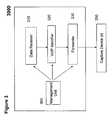
- FIG. 1is a block diagram illustrating an exemplary current technology based system for capturing phone calls.
- the system 1000is applicable to capture of phone calls made using an analog or digital Private Automatic Branch Exchange (PABX) or Public Switched Telephone Network (PSTN).
- PABXPrivate Automatic Branch Exchange
- PSTNPublic Switched Telephone Network
- the capturing equipment 110taps the lines 150 which connect a telephone 120 , and an analog or a digital Private Automatic Branch Exchange (PABX) 130 or Public Switched Telephone Network (PSTN), for capturing phone calls.
- PABXPrivate Automatic Branch Exchange
- PSTNPublic Switched Telephone Network
- VoIPVoice over Internet Protocol
- Data networkssuch as the Internet do not use circuit switching, but are rather based on packet switching.
- the data networkssend and retrieve data on demand. That is to say, instead of routing the data over a dedicated line, data packets flow through a data network along thousands of possible paths. Thus, such communication is relatively diffused evenly across a WAN (wide area network) or LAN (local area network).
- WANwide area network
- LANlocal area network
- VoIP technology capabilitiesmay be used to provide phone service. VoIP has several advantages over circuit switching.
- packet switchingallows several telephone calls to occupy the amount of space occupied by only one in a circuit-switched network.
- Each telephone call's datahas its own data packets, but all packets are sent through the same network space.
- FIG. 2is a block diagram illustrating a VoIP phone connection to a local computer network.
- VoIP phone callsthere is no connection to a PABX, instead the phone 210 is connected to an access switch 220 , which is a part of the data communication network of an organization.
- circuit-switched telephone call recording systems installed in a circuit-switched environmentmay operate by tapping the extensions or trunks coupled to a circuit-loop switch.
- the recording systemmay use the service observation feature of the circuit-loop switch or a dedicated recording connection to observe silently an extension.
- a locally installed systemrequires expensive dedicated hardware. Takes up room, costs money and you need enough to cover all possible connection paths.
- an organization having multiple remote officesmay hire dedicated expensive tie lines for sending the audio to be stored at a central location.
- an apparatus for Voice over IP capturing in a networkcomprising: a data receiver, tapping the network and configured to receive at least one data packet transmitted in the network, a VoIP identifier, associated with the data receiver, configured to determine if the received data packet is a VoIP data packet qualifying for forwarding to a capture device, and a forwarder, associated with the VoIP identifier, configured to forward a copy of the qualifying VoIP data packet to at least one capture device, and to forward the received data packets back to the network.
- a system for Voice over IP capturing in a networkcomprising: a data receiver, tapping the network and configured to receive at least one data packet transmitted in the network, a VoIP identifier, associated with the data receiver, configured to determine if the received data packet is a VoIP data packet qualifying for forwarding to a capture device, a remote capture device, configured to receive a copy of the qualifying VoIP data packet, and a forwarder, associated with the VoIP Identifier, communicating with the remote capture device, and configured to forward a copy of the qualifying VoIP data packet to the remote capture device.
- a method for Voice over IP capturing in a networkcomprising: receiving at least one data packet transmitted in the network by tapping the network, determining if the received data packet is a VoIP data packet qualifying for forwarding to a capture device, forwarding a copy of each of the qualifying VoIP data packets to at least one capture device, and forwarding the received data packets back to the network.
- a system for Voice over IP capturing in a networkcomprising: a centrally located capture device, configured to receive data packets from remote forwarders, and a plurality of remote forwarders, each one of the remote forwarders being deployed at respective local network locations, the remote forwarder tapping the network and configured to receive at least one data session from the local network and to forward the data session to the centrally located capture device.
- Implementation of the method and system of the present inventioninvolves performing or completing certain selected tasks or steps manually, automatically, or a combination thereof. Moreover, according to actual instrumentation and equipment of preferred embodiments of the method and system of the present invention, several selected steps could be implemented by hardware or by software on any operating system of any firmware or a combination thereof.
- selected steps of the inventioncould be implemented as a chip or a circuit.
- selected steps of the inventioncould be implemented as a plurality of software instructions being executed by a computer using any suitable operating system.
- selected steps of the method and system of the inventioncould be described as being performed by a data processor, such as a computing platform for executing a plurality of instructions.
- FIG. 1is a block diagram illustrating an exemplary current technology based system for capturing phone calls.
- FIG. 2is a block diagram illustrating a VoIP phone connection to a local computer network.
- FIG. 3is a block diagram illustrating an apparatus for voice over IP capturing in a network, according to a preferred embodiment of the present invention.
- FIG. 4is a block diagram illustrating a system for voice over IP capturing in a network, according to a preferred embodiment of the present invention.
- FIG. 5 ais a block diagram illustrating an apparatus for voice over IP capturing, connected in a tapping mode, according to a preferred embodiment of the present invention.
- FIG. 5 bis a block diagram illustrating a local network installed with apparatuses for voice over IP capturing, according to a preferred embodiment of the present invention.
- FIG. 5 cis a block diagram illustrating distributed network architecture with apparatuses for voice over IP capturing, according to a preferred embodiment of the present invention.
- FIG. 6 ais a block diagram illustrating an apparatus for VoIP capturing, connected in a mirroring mode, according to a preferred embodiment of the present invention.
- FIG. 6 bis a block diagram illustrating a second distributed network architecture with apparatuses for voice over IP capturing, according to a preferred embodiment of the present invention.
- FIG. 7 ais a block diagram illustrating an apparatus for voice over IP capturing in a network, with connections and peripheral devices, according to a preferred embodiment of the present invention.
- FIG. 7 bis a second block diagram, illustrating an apparatus for voice over IP capturing in a network, with connections and peripheral devices, according to a preferred embodiment of the present invention.
- FIG. 7 cis a block diagram illustrating a relay connection failure mechanism, implemented in an apparatus for VoIP capturing, according to a preferred embodiment of the present invention.
- FIG. 8is a block diagram, illustrating an apparatus for VoIP capturing in network, feeding an array of VoiP loggers, in accordance with a preferred embodiment of the present invention.
- FIG. 9is a flowchart illustrating a method for VoIP capturing, according to a preferred embodiment of the present invention.
- FIG. 10is a block diagram illustrating a low end architecture for VoIP capturing, according to a preferred embodiment of the present invention.
- the present embodimentscomprise an apparatus, system, and method for voice over IP capturing in a network.
- An apparatusis a network device which is configured to capture communication (voice, video, text, etc) carried over voice over internet protocol (VoIP) data traffic in an internet protocol (IP) network.
- VoIPvoice over internet protocol
- IPinternet protocol
- the apparatushas a capacity to identify VoIP data packets in among data packets received by the apparatus from the network, where VoIP data packets as well as non-VoIP data packets are transmitted.
- the apparatusmay then determine, for each of the identified VoIP data packets, if the identified VoIP data packet qualifies for forwarding to a capture device.
- the data packets identified as VoIP data packets and found to qualify for forwardingare then forwarded to one or more active capturing devices such as an active recording VoIP logger.
- the apparatusis also configured to forward data packets received by the apparatus back to the network.
- the forwarding of data packets back to the networkallows the deployment of the apparatus in a tapping mode—for tapping a data transmission link in the network, say a specific VoIP telephone branch.
- the apparatusmay also be deployed in a mirroring mode, as explained in further detail herein below.
- the apparatusmay further include an array of failsafe relays, configured to prevent disconnection in the network link, resultant upon failure of the apparatus (say when the apparatus stops functioning or during a power failure), as described in further detail herein below.
- the present inventionmay be implemented in network where mirroring session services (and tunneled mirroring session services are not supported.
- the tapping modefurther allows the deployment of the apparatus on a simple switch, such as a remote branch access switch used by one or two VoIP telephony device.
- a VoIP telephony devicemay include, but is not limited to: a physical phone, a soft phone, a Wi-Fi phone, VoIP enabled Personal Digital Assist (PDA), and any other known in the art device having VoIP capabilities.
- any switchmay be tapped for capturing the relevant data packets, as no complicated and resource consuming mirroring sessions are required.
- the present inventionmay allow a cheaper and more distributable solution to VoIP capturing, specifically for distributed organizations, such as banks, government agencies, etc.
- a distributed organizationsuch as a bank typically has dozens, hundreds, or even thousands of branches and one or more central facilities. Each branch and each central facility my have a local computer network and all the local networks are connected together.
- VoIP data packetsmay be intercepted locally, at any relevant communication link, in one of the local networks.
- the data packetsmay then be examined with respect to predefined criteria, for determining if the data packets qualify for forwarding to a capture device.
- the qualifying data packetsmay then be sent to one or more capture device(s) located at the central facilities of the distributed organization.
- the capture devicesreceive the forwarded data packets, process the forwarded data packet, and record the then.
- FIG. 3is a block diagram illustrating an apparatus for voice over IP capturing in a network, according to a preferred embodiment of the present invention.
- Apparatus 3000includes a data receiver 310 .
- the data receiver 310taps the network. That is to say, the data receiver 310 connects to a line (or a cable) of the network serially.
- the serial connectionmay be based on any of the OSI model layers. For example, in layer one of the OSI model, the tapping of the network line is physical, whereas in layer two of the OSI model, the tapping is based on a virtual connection made in a switching component.
- the data receiver 310is configured to receive one or more data packet(s), transmitted in the network. More specifically, the data packet(s) may be data packets, transferred through an Internet protocol (IP) network and intercepted by the data receiver 310 .
- IPInternet protocol
- the apparatus 3000further comprises a Voice over Internet Protocol (VoIP) identifier 320 , connected to the data receiver 310 , and configured to determine if a received data packet qualifies for forwarding to a capture device.
- VoIPVoice over Internet Protocol
- the voice over Internet Protocol (VoIP) identifier 320may identify one or more of the data packets received by the data receiver 310 as a VoIP data packet, as described in further detail herein below.
- VoIPvoice over Internet Protocol
- the VoIP identifier 320deems each identified VoIP data packet qualified for forwarding to a capturing device.
- the VoIP identifier 320is also configured to determine whether the identified VoIP data packet qualifies for forwarding to a capturing device, according to a user predefined policy, say utilizing data packet classification capabilities or any other method, as described in greater detail herein below.
- the voice over Internet Protocol (VoIP) identifier 320is further configured to qualify only VoIP data packets used for implementing a telephony service for forwarding to a capture device.
- VoIPvoice over Internet Protocol
- the apparatus 3000also includes a forwarder 330 , connected to Internet Protocol (VoIP) identifier 320 .
- the forwarder 330forwards a copy of each data packet, qualified by the VoIP identifier 320 , to one or more capture device(s) 350 , communicating with the forwarder 330 .
- VoIPInternet Protocol
- the VoIP identifier 320is further configured to select which of the capture device(s) 350 a specific qualified data packet is to be forwarded to, according to a predefined forwarding-policy that may comprise a hash formula, as described in further detail herein below.
- At least one, but optionally and more preferably all of the entities or parties which participate in the recorded/monitored sessionare able to duplicate the received and sent data, and then to forward the data to the recording/monitoring system.
- the datais forwarded after only minimal address information is provided and/or changed, such that for example preferably only the destination IP address and port are changed, for example for data that is transmitted as IP packets.
- the datais preferably forwarded with minimum pre-processing.
- the forwarder 330may also communicate one or more capture device(s) with additional information.
- the additional information communicated to the capture device(s) by the forwarder 330may include, but is not limited to: a list of telephony devices accessible to the data receiver 310 , the type of communications receivable by the data receiver 310 , etc.
- the forwarder 330may additionally process the data packet prior to forwarding the data packet.
- the additional processing carried out by the forwardermay include, but is not limited to: encrypting the data packet, re-packing the data packet, compressing the data packet, etc.
- apparatus 3000further includes a management unit 360 .
- the management unit 360may be used by the user for configuring the apparatus, monitoring the apparatus, etc. More preferably, the management unit 360 remotely communicates with the apparatus 30000 .
- the management unit 360may be used by the user for defining rules for the VoIP Identifier 320 to follow, for identifying a data packet as a VoIP data packet, for determining if an identified VoIP data packet qualifies for forwarding to a capture device, etc.
- FIG. 4is a block diagram, illustrating a system for voice over IP capturing in a network, according to a preferred embodiment of the present invention.
- the System 4000includes a data receiver 410 .
- the data receiver 410is configured to receive one or more data packet(s), transmitted in the network. More specifically, the data packet(s) may be data packets, transferred through an Internet protocol (IP) network and intercepted by the data receiver 410 , as described hereinabove.
- IPInternet protocol
- the system 4000further comprises a Voice over Internet Protocol (VoIP) identifier 420 , connected to the data receiver 410 .
- VoIPVoice over Internet Protocol
- the voice over Internet Protocol (VoIP) identifier 420identifies one or more of the data packets received by the data receiver 410 as a VoIP data packet(s), as described in further detail herein below.
- VoIPvoice over Internet Protocol
- the VoIP identifier 420deems each identified VoIP data packet qualified for forwarding to a capturing device.
- the VoIP identifier 420also determines whether the identified VoIP data packet qualifies for forwarding to a capturing device, according to a user predefined policy, say utilizing data packet classification capabilities or any other method, as described in greater detail herein below.
- VoIP used for implementing a telephony serviceare found to qualify for forwarding to a capture device.
- the system 4000also includes a forwarder 430 , connected to Internet Protocol (VoIP) identifier 420 .
- VoIPInternet Protocol
- the forwarder 430forwards each data packet, which was found qualifying, utilizing the VoIP identifier 420 , to a capture device(s) 450 , remotely communicating with the forwarder 430 .
- the VoIP identifier 320is further configured to select which of the capture device(s) 350 a specific qualified data packet is to be forwarded to, say using a hash formula, as described in further detail herein below.
- system 400further includes a remote management unit 460 .
- the management unit 460may be used by the user for configuring the apparatus, monitoring the apparatus, etc, as described in further detail hereinabove.
- FIG. 5 ais a block diagram, illustrating an apparatus for voice over IP capturing, connected in a tapping mode, according to a preferred embodiment of the present invention.
- Apparatus 500taps a communication link between an access switch 510 and a gateway 520 linking the network to a public switching telephony network (PTSN) 530 .
- the access switch 510connects one or more voice over IP (VoIP) phones 515 via the computers 517 associated with the phones 515 .
- VoIPvoice over IP
- the apparatus 500connected in a mode tapping the link between the gateway 520 and the access switch 510 , receives all data transmitted between the network and the computers 517 .
- the apparatus 500is configured to identify VoIP telephony data packets transmitted through the communication link.
- the apparatus 500may be configured to determine, for each identified data packet, whether the identified data packet qualifies for forwarding to a capture device, such as a VoIP logger 540 .
- the decisionmay be carried out utilizing a variety of criteria, as described in further detail herein below.
- the apparatus 500forwards a copy of each of the qualifying VoiP data packets, to the capture device 540 .
- the apparatusalso forwards each data packet received by the apparatus back to the network, thus facilitating a tapping mode without mirroring sessions implemented at the access switch 510 .
- the apparatus 500also includes a mechanism for securing against disconnection of the tapped line, resultant upon failure of the apparatus 500 .
- the failuremay occur when the apparatus 500 stops functioning, during power failure, etc.
- the apparatusmay include a failsafe relay mechanism for shortening between pairs of lines used by the apparatus 500 for receiving the data packets, as described in further detail herein below.
- FIG. 5 bis a block diagram, illustrating a local network installed with apparatuses for voice over IP capturing, according to a preferred embodiment of the present invention.
- Apparatuses 550are deployed in a tapping mode where the apparatuses 550 tap the links between distribution switches 560 and routers 570 in the local network. As a result, all data packets transferred between the distribution switches 560 and routers 570 pass through the apparatuses 550 .
- the routers 570link the local network to external networks such as public switching telephony network (PSTN) 591 , and a wide area network (WAN) 592 .
- PSTNpublic switching telephony network
- WANwide area network
- Each distribution switch 560is typically connected to one or more access switches 580 .
- the access switches 580are used for connecting VoiP telephones and computers to the local network, for providing VoIP based telephony.
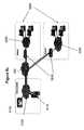
- FIG. 5 cis a block diagram, illustrating distributed network architecture with apparatuses for voice over IP capturing, according to a preferred embodiment of the present invention.
- a distributed organization(such as a bank, a government agency, etc) has several branches and a central management facility.
- the organizationhas a data center 5100 equipped with VoIP loggers 5110 , for remotely logging phone calls at the branches 5200 of the organization.
- the organizationfurther deploys the apparatuses 5210 for capturing incoming and outgoing VoiP phone calls.
- the apparatuses 5210are deployed in a tapping mode, tapping the communication link between each local branch network 5235 and a wide area network (WAN) 5300 connecting the local branch networks 5235 and the local network 5125 at the data center 5100 .
- WANwide area network
- the apparatuses 5210identify VoIP data packets, determining whether the identified units qualify for forwarding, and forward a copy of each qualifying data packet to the loggers at the data center 5100 .
- all data packets receivedare forwarded back to the network, as described in further detail hereinabove.
- FIG. 6 ais a block diagram, illustrating an apparatus for VoIP capturing, connected in a mirroring mode, according to a preferred embodiment of the present invention.
- Apparatus 600is connected to an access switch 610 in a mirroring mode, through mirroring ports on the access switch 610 .
- the access switchsupports mirroring sessions which are utilized for VoIP data capturing by the apparatus 600 .
- the apparatus 600receives copies of data packets transferred through the switch 610 , via the mirroring ports.
- the data transferred through the switch 610is mirrored such that a copy of each of the transferred data packets is received by the apparatus 600 .
- the apparatus 600connects through the mirroring ports, without directly tapping the communication link between the access switch 610 connecting one or more voice over IP (VoIP) phones 615 via the computers 617 associated with the phones 615 , and a gateway 620 linking the network to a public switching network (PTSN) 630 .
- VoIPvoice over IP
- PTSNpublic switching network
- FIG. 6 bis a block diagram, illustrating a second distributed network architecture with apparatuses for voice over IP capturing, according to a preferred embodiment of the present invention.
- a distributed organizationmay have a distributed computer network, as illustrated and described in detail hereinabove.
- the apparatuses 6210may be installed in a mirroring mode, such that each of the apparatuses 6210 receives a copy of each of the data packets transmitted through a switch, via mirroring ports, as described hereinabove.
- the apparatuses 6210send identified and qualified VoIP data packets to the VoIP loggers 6110 , at the data center, as explained in further detail hereinabove.
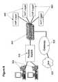
- FIG. 7 ais a block diagram, illustrating an apparatus for voice over IP capturing in a network, with connections and peripheral devices, according to a preferred embodiment of the present invention.
- An apparatus 7109is serially connected between a local area network (LAN) Switch 7101 and a VoIP Phone 7102 .
- the apparatus 7109taps the traffic of data packets that the VoIP phone 7102 receives and transmits, and analyzes the type of each received data packet.
- LANlocal area network
- the apparatus 7109Upon receiving a data packet identified as a RTP data packet (RTP is real-time transport protocol—the Internet-standard protocol for the transport of real-time data including audio and video), the apparatus 7109 forwards the identified RTP data packet to the capture equipment.
- the forwardingmay be done by transmitting the data packet to a LAN Switch 7101 , which is also used by the VoIP phone 7102 . If the forwarding can not be done on the same Switch 7101 that the VoIP phone uses, the device forwards the identified data packet via another Switch port 7107 .
- the apparatus 7109further has a capability to receive data packets destined to the phone 7102 and playback the voice data, which is in the data packet, to an external speaker 7108 .
- the devicemay further have the capability to record voice via a microphone 7110 and send the recorded voice to a desired IP address.
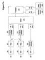
- FIG. 7 bis a second block diagram, illustrating an apparatus for voice over IP capturing in a network, with connections and peripheral devices, according to a preferred embodiment of the present invention.
- FIG. 7 bdepicts in further detail the apparatus and peripherals described hereinabove using FIG. 7 a.
- the LAN Switch port 7101is connected to a RJ-45 connector b 4 via a network cable (b 1 ).
- the VoIP phone 7102is connected to a RJ-45 connector (b 5 ) via a network cable (b 2 ). Both connections are routed to Ethernet 10/100/1000 transformers (b 10 , b 11 ) through relay units (b 7 , b 8 ).
- the relay units (b 7 , b 8 )perform a failsafe mechanism which bypasses the device in case of failure.
- the relay units (b 7 , b 8 )shorten the wires as shown and explained in greater detail, using FIG. 7 c , herein below.
- the two portsare connected to physical links (b 12 , b 13 ), and then to a switch (b 15 ).
- the switch (b 15 )switches the data packets from the LAN switch to both the phone and the processor.
- the switchswitches the data packets from the phone to both the LAN Switch and the processor (b 16 ). In that way the link between the LAN Switch and the phone is well established, while the processor also receives all the data packets.
- the processor (b 16 )analyzes the units and determines, using pre-defined rules (e.g. according to predefined IP address lists, according to RTP compliance of a data packet, etc.) whether the data packet qualifies for forwarding to the capture equipment.
- pre-defined rulese.g. according to predefined IP address lists, according to RTP compliance of a data packet, etc.
- the playback capabilityis provided using a digital-to-analog D/A converters (b 18 ).
- the recording capabilityis provided using an analog-to digital converter A/D (b 17 ).
- FIG. 7 cis a block diagram illustrating a relay connection failure mechanism, implemented in an apparatus for VoIP capturing, according to a preferred embodiment of the present invention.
- an apparatusmay be connected in a tapping mode.
- the apparatustaps a communication link in the network, such that all data packets transferred through the communication link are input to the apparatus.
- Data packets identified as VoIP data packets and found qualifyingare sent to one or more capture device(s), as described hereinabove. All data packets are forwarded back to the network, thereby facilitating the tapping mode, as explained hereinabove.
- the tapped linkmay be disconnected.
- the apparatusmay stop functioning, a power failure may occur, etc.
- the apparatus for VoIP capturingincludes a failure mechanism for securing against disconnection of the tapped network link, resultant upon failure of the apparatus.
- the apparatusPreferably, there are two or more input channels used by the apparatus, connected to the network, for receiving the data packets from the network.
- the apparatusincludes one or more one relay devices. Each relay device is configured to connect a pair of the input channels, thereby preventing link disconnection in the network.
- each of the input channelscomprises a RJ-45 ( 7311 - 7312 ) connector.
- a RJ-45 connectorincludes eight pins ( 1 - 8 ).
- a failsafe mechanismincludes an array of relays.
- the relaysarrange such that each pin of one RJ-45 ( 7311 ) connector in the pair is connected to a matching pin of the other RJ-45 ( 7312 ) connector in the pair.
- pin 8 of the RJ-45 ( 7311 ) connectorelectrically connects to pin 8 of the RJ-45 ( 7312 ) connector, via a conductive path 7301 .
- a magnetic field powered by the operating apparatusarranges the relays such that the two pins 8 are not connected, but rather each pin electrically connects to one of the transformers (b 10 , b 11 ).
- FIG. 8is a block diagram, illustrating an apparatus for VoIP capturing in network, feeding an array of VoiP loggers, in accordance with a preferred embodiment of the present invention.
- Apparatus 800taps the communication link between an access switch 810 and gateway 820 connecting the network and a public switched telephony network 825 .
- the access switch 810is connected to VoiP phones 830 .
- the apparatus 800is configured to identify VoIP telephony data packets among the data packets transmitted through the tapped network link and received by the apparatus 800 .
- the apparatus 800identifies the VoIP telephony data packets according to a user pre-definable policy.
- the apparatus 800is also configured to determine, for each identified data packet, whether the identified data packet qualifies for forwarding to one of the VoIP loggers 840 .
- the decisionmay be carried out according to a variety of criteria, as described in further detail herein below.
- the apparatus 800also forwards each of the received data packets back to the network, thus facilitating tapping mode VoIP capturing, as explained in further detail hereinabove.
- the apparatus 800For each of the VoIP data packets, found to qualify for forwarding to a VoIP logger 840 , the apparatus 800 selects one of the loggers 840 , and forwards the identified qualifying data packet to the VoiP logger.
- the selection of a logger among the VoIP loggers 840is carried out according to a user predefined forwarding-policy.
- the forwarding-policymay allow load balancing the array of VoiP loggers 840 , live back-upping (and recovering), etc.
- the forwarding-policyis based on a hash formula, as discussed in further detail herein below.
- FIG. 9is a flowchart illustrating a method for VoIP capturing, according to a preferred embodiment of the present invention.
- data packets transferred through a communication link in the networkare receive 910, say by a data receiver 310 , as described hereinabove.
- each received data packetis examined for determining its qualification for forwarding to a capture device, say by the VoIP identifier 320 , as described hereinabove.
- VoIP data packetsare identified among the received data packets.
- the identified VoIP data packetsare examined with respect to predefined criteria, and a decision is made with regards to each of the identified VoIP data packets, whether the specific data packet qualifies for forwarding to a capture device, as discussed in greater detail herein below.
- data packets found to qualify for forwardingare forwarded 930 to one or more capture device(s).
- the predefined forwarding-policymay be based on a hash formula, or any other criteria, as described in further detail herein below.
- received data packetsare forwarded back 950 to the network.
- the forwarding of received data packets back to the networkfacilitates tapping mode VoIP capturing, as described in detail hereinabove.
- Identifying 920 data packets as VoIP data packets, and determining if the data packets qualify for forwarding to a capture devicemay be carried out according to predefined rules, the may be based on a variety of criteria, including but not limited to:
- UDPUser Datagram Protocol
- RTPReal-time transport protocol
- TCPTransmission Control Protocol
- DSCPDifferentiated Services Code Point
- VLAN tagan Ethernet header extension that enlarges the header from fourteen to eighteen bytes.
- the VLAN tagcontains the VLAN ID and priority.
- the data packetsmay be identified as VoIP data packets based on compliance with a standard such as the User Datagram Protocol (UDP) or the Real-time transport protocol (RTP), say by the VoIP identifier 320 , as described hereinabove.
- UDPUser Datagram Protocol
- RTPReal-time transport protocol
- each data packet identified as a VoiP data packetqualifies for forwarding to a capture device, such as a VoiP logger.
- a decisionis then made, with respect to each data packet identified as a VoIP data packet, based on more specific criteria, if the data packet qualifies for forwarding to a capture device.
- a list of IP (or MAC) addressesmay be predefined by a user, and only identified VoiP data packets bearing one of the addresses, as a destination or as an origin, are found to qualify for forwarding to a capture device such as a VoIP logger.
- the capture devicesthere are two or more capture devices such as VoiP loggers, and one of the capture devices is selected for receiving each specific qualified data packet, say by the VoIP identifier 320 , as described hereinabove.
- the selection of the receiving capture deviceis carried out according to a predefined forwarding-policy.
- the selection of the capture deviceis carried out according to a forwarding-policy based on a hash formula, such that the qualified data packets are uniformly distribution among the capture devices.
- a forwarding-policybased on a hash formula
- the load balancingis achieved with minimum configuration effort by a user of an apparatus for VoiP capturing, as described hereinabove.
- the hash formulamay a mathematical formula which when applied on predefined fields of the data packet produces a value identifying one of the capture devices, such that a uniform distribution of such values is achieved for the many data packets received and qualified for forwarding.
- each data packetmay be forwarded to two of the capture devices, thereby providing a live baking-up scheme for all qualified data packets.
- a High-end architectureand a low-end architecture.
- Each of the architecturesinvolves connecting the apparatus 3000 to the network in a tapping mode, or in a mirroring mode.
- the high-end architectureis tailored for a case where a large number of VoIP phones are to be forwarded to the VoIP Logger.
- the binding point for the high-endmay be between any network components as depicted in FIGS. 5 a , 5 b and 5 c for tapping and 6 a , 6 b and 6 c for mirroring, hereinabove.
- FIG. 10is a block diagram illustrating a low end architecture for VoIP capturing, according to a preferred embodiment of the present invention.
- the low-end architectureis tailored for a case where a small number of VoIP phones 1010 are to be forwarded or where the high-end architecture can not be implemented in the network.
- the binding point for the low-endis between an access switch 1020 and a VoIP phone 1010 or computer.
- FIGS. 7 a , 7 b and 7 cmay serve to illustrate possible apparatuses and mechanisms, usable for implanting the low end architecture.
Landscapes
- Engineering & Computer Science (AREA)
- Signal Processing (AREA)
- Computer Networks & Wireless Communication (AREA)
- Multimedia (AREA)
- Computer Security & Cryptography (AREA)
- Technology Law (AREA)
- Computer Hardware Design (AREA)
- Computing Systems (AREA)
- General Engineering & Computer Science (AREA)
- Data Exchanges In Wide-Area Networks (AREA)
- Telephonic Communication Services (AREA)
Abstract
Description
- A predefined list of Media Access Control (MAC) addresses.
- A type of a protocol implemented in the data packet
- Any other of the fields in the header of the data packet.
- Or any other information residing in the packet According to a preferred embodiment of the present invention, the data packets are identified as VoiP data packets, according to general criteria.
Claims (25)
Priority Applications (2)
| Application Number | Priority Date | Filing Date | Title |
|---|---|---|---|
| US11/452,917US8165114B2 (en) | 2002-06-13 | 2006-06-15 | Voice over IP capturing |
| PCT/IL2007/000111WO2007144867A2 (en) | 2006-06-15 | 2007-01-29 | Voice over ip capturing |
Applications Claiming Priority (4)
| Application Number | Priority Date | Filing Date | Title |
|---|---|---|---|
| US38792502P | 2002-06-13 | 2002-06-13 | |
| PCT/IL2003/000109WO2003107622A1 (en) | 2002-06-13 | 2003-02-12 | A mthod fo recording a multimidia conference |
| US10/913,326US7474633B2 (en) | 2002-06-13 | 2004-08-09 | Method for forwarding and storing session packets according to preset and/or dynamic rules |
| US11/452,917US8165114B2 (en) | 2002-06-13 | 2006-06-15 | Voice over IP capturing |
Related Parent Applications (1)
| Application Number | Title | Priority Date | Filing Date |
|---|---|---|---|
| US10/913,326Continuation-In-PartUS7474633B2 (en) | 2002-06-13 | 2004-08-09 | Method for forwarding and storing session packets according to preset and/or dynamic rules |
Publications (2)
| Publication Number | Publication Date |
|---|---|
| US20060268847A1 US20060268847A1 (en) | 2006-11-30 |
| US8165114B2true US8165114B2 (en) | 2012-04-24 |
Family
ID=38832198
Family Applications (1)
| Application Number | Title | Priority Date | Filing Date |
|---|---|---|---|
| US11/452,917Active2026-02-21US8165114B2 (en) | 2002-06-13 | 2006-06-15 | Voice over IP capturing |
Country Status (2)
| Country | Link |
|---|---|
| US (1) | US8165114B2 (en) |
| WO (1) | WO2007144867A2 (en) |
Cited By (10)
| Publication number | Priority date | Publication date | Assignee | Title |
|---|---|---|---|---|
| US20100322232A1 (en)* | 2009-06-18 | 2010-12-23 | Ambit Microsystems (Shanghai) Ltd. | Modem and calling packet processing method thereof |
| US20120121260A1 (en)* | 2006-12-22 | 2012-05-17 | Verizon Patent And Licensing Inc. | System for intercepting signals to be transmitted over a fiber optic network and associated method |
| US20130054737A1 (en)* | 2011-08-29 | 2013-02-28 | Carlos Miranda | System and Method for Data Acquisition in an Internet Protocol Network |
| US9270826B2 (en) | 2007-03-30 | 2016-02-23 | Mattersight Corporation | System for automatically routing a communication |
| US20160065465A1 (en)* | 2014-08-29 | 2016-03-03 | Metaswitch Networks Limited | Packet recording |
| US9432511B2 (en) | 2005-05-18 | 2016-08-30 | Mattersight Corporation | Method and system of searching for communications for playback or analysis |
| US10642889B2 (en) | 2017-02-20 | 2020-05-05 | Gong I.O Ltd. | Unsupervised automated topic detection, segmentation and labeling of conversations |
| US11227606B1 (en)* | 2019-03-31 | 2022-01-18 | Medallia, Inc. | Compact, verifiable record of an audio communication and method for making same |
| US11276407B2 (en) | 2018-04-17 | 2022-03-15 | Gong.Io Ltd. | Metadata-based diarization of teleconferences |
| US11398239B1 (en) | 2019-03-31 | 2022-07-26 | Medallia, Inc. | ASR-enhanced speech compression |
Families Citing this family (33)
| Publication number | Priority date | Publication date | Assignee | Title |
|---|---|---|---|---|
| US7660297B2 (en)* | 2002-06-13 | 2010-02-09 | Nice Systems Ltd. | Voice over IP forwarding |
| GB2389736B (en) | 2002-06-13 | 2005-12-14 | Nice Systems Ltd | A method for forwarding and storing session packets according to preset and/or dynamic rules |
| US8094803B2 (en) | 2005-05-18 | 2012-01-10 | Mattersight Corporation | Method and system for analyzing separated voice data of a telephonic communication between a customer and a contact center by applying a psychological behavioral model thereto |
| US9002313B2 (en) | 2006-02-22 | 2015-04-07 | Federal Signal Corporation | Fully integrated light bar |
| US9346397B2 (en) | 2006-02-22 | 2016-05-24 | Federal Signal Corporation | Self-powered light bar |
| US7476013B2 (en) | 2006-03-31 | 2009-01-13 | Federal Signal Corporation | Light bar and method for making |
| US7746794B2 (en) | 2006-02-22 | 2010-06-29 | Federal Signal Corporation | Integrated municipal management console |
| US7903568B2 (en)* | 2006-06-29 | 2011-03-08 | Verint Americas Inc. | Systems and methods for providing recording as a network service |
| US7958207B2 (en)* | 2006-07-10 | 2011-06-07 | Koninklijke Philips Electronics N.V. | Method of installing software for enabling a connection of a phone to an interconnected network |
| US7613290B2 (en) | 2006-09-29 | 2009-11-03 | Verint Americas Inc. | Recording using proxy servers |
| US7570755B2 (en)* | 2006-09-29 | 2009-08-04 | Verint Americas Inc. | Routine communication sessions for recording |
| US8130925B2 (en) | 2006-12-08 | 2012-03-06 | Verint Americas, Inc. | Systems and methods for recording |
| US8280011B2 (en) | 2006-12-08 | 2012-10-02 | Verint Americas, Inc. | Recording in a distributed environment |
| US8130926B2 (en) | 2006-12-08 | 2012-03-06 | Verint Americas, Inc. | Systems and methods for recording data |
| US8599747B1 (en)* | 2006-12-20 | 2013-12-03 | Radisys Canada Inc. | Lawful interception of real time packet data |
| US9276903B2 (en)* | 2007-01-11 | 2016-03-01 | Nice-Systems Ltd. | Branch IP recording |
| US8023639B2 (en) | 2007-03-30 | 2011-09-20 | Mattersight Corporation | Method and system determining the complexity of a telephonic communication received by a contact center |
| US8358591B2 (en)* | 2007-06-06 | 2013-01-22 | Hewlett-Packard Development Company, L.P. | Network traffic monitoring in a server network environment |
| US20090010277A1 (en)* | 2007-07-03 | 2009-01-08 | Eran Halbraich | Method and system for selecting a recording route in a multi-media recording environment |
| KR100835654B1 (en) | 2007-09-20 | 2008-06-05 | (주)해창시스템 | Packet information retrieval apparatus and method through Dx splitting and query splitting for packet information |
| US10419611B2 (en) | 2007-09-28 | 2019-09-17 | Mattersight Corporation | System and methods for determining trends in electronic communications |
| KR100835647B1 (en) | 2007-10-17 | 2008-06-05 | (주)해창시스템 | Apparatus and method for managing statistical data of captured packets to extract and manage real-time statistical data and trend data of captured packets for real-time monitoring and performance trend analysis in BOP network |
| JP4911010B2 (en)* | 2007-12-11 | 2012-04-04 | 富士通株式会社 | Packet capture device, packet capture method, and packet capture program |
| US7940658B2 (en)* | 2008-09-04 | 2011-05-10 | Cisco Technology, Inc. | ERSPAN dynamic session negotiation |
| WO2011009796A1 (en) | 2009-07-20 | 2011-01-27 | S.A.M. Steffens Beheer B.V. | Transcoding audio of a recorded telephone call for distributing as data file |
| US8520540B1 (en) | 2010-07-30 | 2013-08-27 | Cisco Technology, Inc. | Remote traffic monitoring through a network |
| US9014060B2 (en) | 2012-06-21 | 2015-04-21 | Level 3 Communications, Llc | System and method for integrating VoIP client for audio conferencing |
| US9077619B2 (en) | 2012-09-18 | 2015-07-07 | Cisco Technology, Inc. | Exporting real time network traffic latency and buffer occupancy |
| US9054967B1 (en) | 2012-09-18 | 2015-06-09 | Cisco Technology, Inc. | Timestamping packets in a network |
| US9094307B1 (en) | 2012-09-18 | 2015-07-28 | Cisco Technology, Inc. | Measuring latency within a networking device |
| JP6258562B2 (en)* | 2015-06-02 | 2018-01-10 | 三菱電機ビルテクノサービス株式会社 | Relay device, network monitoring system, and program |
| US10003688B1 (en) | 2018-02-08 | 2018-06-19 | Capital One Services, Llc | Systems and methods for cluster-based voice verification |
| US11522993B2 (en)* | 2020-04-17 | 2022-12-06 | Marchex, Inc. | Systems and methods for rapid analysis of call audio data using a stream-processing platform |
Citations (60)
| Publication number | Priority date | Publication date | Assignee | Title |
|---|---|---|---|---|
| US200311A (en) | 1878-02-12 | Improvement in car-couplings | ||
| US5099510A (en) | 1990-06-11 | 1992-03-24 | Communications Network Enhancement Inc. | Teleconferencing with bridge partitioning and other features |
| US5101402A (en) | 1988-05-24 | 1992-03-31 | Digital Equipment Corporation | Apparatus and method for realtime monitoring of network sessions in a local area network |
| US5515376A (en)* | 1993-07-19 | 1996-05-07 | Alantec, Inc. | Communication apparatus and methods |
| US5559875A (en) | 1995-07-31 | 1996-09-24 | Latitude Communications | Method and apparatus for recording and retrieval of audio conferences |
| US5710591A (en) | 1995-06-27 | 1998-01-20 | At&T | Method and apparatus for recording and indexing an audio and multimedia conference |
| EP0841832A2 (en) | 1996-11-08 | 1998-05-13 | AT&T Corp. | Promiscuous network monitoring utilizing multicasting within a switch |
| US5764901A (en) | 1995-12-21 | 1998-06-09 | Intel Corporation | Record and playback in a data conference |
| US5787253A (en) | 1996-05-28 | 1998-07-28 | The Ag Group | Apparatus and method of analyzing internet activity |
| US5841977A (en) | 1995-08-24 | 1998-11-24 | Hitachi, Ltd. | Computer-based conferencing system with local operation function |
| US5867559A (en) | 1996-02-20 | 1999-02-02 | Eis International, Inc. | Real-time, on-line, call verification system |
| EP0902569A1 (en) | 1997-09-11 | 1999-03-17 | AT&T Corp. | Method and system for a unicast endpoint client to access a multicast internet protocol (ip) session |
| US5893053A (en) | 1995-09-19 | 1999-04-06 | Sony Corporation | Computer graphics data recording and playback system with a VCR-based graphic user interface |
| WO1999046702A1 (en) | 1998-03-13 | 1999-09-16 | Siemens Corporate Research, Inc. | Apparatus and method for collaborative dynamic video annotation |
| US5963913A (en) | 1997-02-28 | 1999-10-05 | Silicon Graphics, Inc. | System and method for scheduling an event subject to the availability of requested participants |
| US5978835A (en) | 1993-10-01 | 1999-11-02 | Collaboration Properties, Inc. | Multimedia mail, conference recording and documents in video conferencing |
| US6006253A (en) | 1997-10-31 | 1999-12-21 | Intel Corporation | Method and apparatus to provide a backchannel for receiver terminals in a loosely-coupled conference |
| US6108782A (en) | 1996-12-13 | 2000-08-22 | 3Com Corporation | Distributed remote monitoring (dRMON) for networks |
| US6122665A (en) | 1998-08-26 | 2000-09-19 | Sts Software System Ltd. | Communication management system for computer network-based telephones |
| US6181784B1 (en) | 1991-05-21 | 2001-01-30 | Vtel Corporation | Computer controlled video multiplexer for video conferencing and message systems |
| WO2001060027A2 (en) | 2000-02-14 | 2001-08-16 | Nice Systems Ltd. | Telephone call monitoring system |
| US6311231B1 (en) | 1995-09-25 | 2001-10-30 | Thomas Howard Bateman | Method and system for coordinating data and voice communications via customer contract channel changing system using voice over IP |
| WO2001091374A1 (en) | 2000-05-24 | 2001-11-29 | Telefonaktiebolaget Lm Ericsson (Publ) | Method and apparatus for intercepting packets in a packet-oriented network |
| US20010052081A1 (en)* | 2000-04-07 | 2001-12-13 | Mckibben Bernard R. | Communication network with a service agent element and method for providing surveillance services |
| US20020006187A1 (en) | 2000-04-17 | 2002-01-17 | Guenter Lukas | Method and system for recording communication data |
| WO2002017036A2 (en) | 2000-08-18 | 2002-02-28 | Kagoor Networks, Inc. | Method and apparatus for monitoring and processing voice over internet protocol packets |
| US20020027977A1 (en) | 2000-09-04 | 2002-03-07 | Nec Corporation | Data recording system for IP telephone communication |
| WO2002019620A2 (en) | 2000-08-28 | 2002-03-07 | Nice Systems Ltd. | Digital recording of ip based distributed switching platform |
| US20020116464A1 (en) | 2001-02-20 | 2002-08-22 | Mak Joon Mun | Electronic communications system and method |
| US6490344B1 (en) | 1999-10-04 | 2002-12-03 | Kabushiki Kaisha Toshiba | Communication system and communication channel coupling method |
| US6504907B1 (en)* | 1998-03-26 | 2003-01-07 | Verizon Services Corp. | Call detail reporting for lawful surveillance |
| US20030007486A1 (en)* | 2001-06-14 | 2003-01-09 | March Sean W. | Network address and/or port translation |
| US6535909B1 (en) | 1999-11-18 | 2003-03-18 | Contigo Software, Inc. | System and method for record and playback of collaborative Web browsing session |
| US6549516B1 (en) | 1999-07-02 | 2003-04-15 | Cisco Technology, Inc. | Sending instructions from a service manager to forwarding agents on a need to know basis |
| US6553025B1 (en) | 1999-08-18 | 2003-04-22 | At&T Corp. | Multiple routing and automatic network detection of a monitored call from an intercepted targeted IP phone to multiple monitoring locations |
| US20030095567A1 (en)* | 2001-11-20 | 2003-05-22 | Lo Man Kuk | Real time protocol packet handler |
| US6574335B1 (en)* | 1999-12-22 | 2003-06-03 | At&T Corp. | Method for simulating a ring back for a call between parties in different communication networks |
| US20030107991A1 (en) | 2001-12-12 | 2003-06-12 | Yasuo Tezuka | Congestion control system for VoIP network |
| US6647020B1 (en)* | 1999-12-17 | 2003-11-11 | Motorola, Inc. | Methods for implementing a talkgroup call in a multicast IP network |
| US20030219025A1 (en)* | 2002-05-27 | 2003-11-27 | Samsung Electronics Co., Ltd. | Gateway having bypassing apparatus |
| US6661879B1 (en) | 2000-07-19 | 2003-12-09 | Xtend Communications Corp. | System and method for recording telephonic communications |
| US20040141594A1 (en) | 2003-01-20 | 2004-07-22 | Brunson Gordon R. | Messaging advise in presence-aware networks |
| US20040165709A1 (en) | 2003-02-24 | 2004-08-26 | Pence Robert Leslie | Stealth interception of calls within a VoIP network |
| US20040228627A1 (en)* | 2003-05-15 | 2004-11-18 | International Business Machines Corporation | Highly available redundant optical modules using single network connection |
| US6839323B1 (en) | 2000-05-15 | 2005-01-04 | Telefonaktiebolaget Lm Ericsson (Publ) | Method of monitoring calls in an internet protocol (IP)-based network |
| EP1512263A1 (en) | 2002-06-13 | 2005-03-09 | Nice Systems Ltd. | A method of recording a multimedia conference |
| US6876633B2 (en) | 1997-10-21 | 2005-04-05 | Intel Corporation | Apparatus and method for computer telephone integration in packet switched telephone networks |
| US20050094651A1 (en) | 2003-10-30 | 2005-05-05 | Alcatel | Lawful interception gateway |
| US20050141691A1 (en) | 2003-12-31 | 2005-06-30 | Wengrovitz Michael S. | Method for transferring calls between PBX telephone and SIP client |
| US20050175156A1 (en)* | 2004-02-05 | 2005-08-11 | Afshar Siroos K. | Calea in a VPN environment (formerly called restricted anti-calea |
| US6940835B2 (en)* | 2000-12-28 | 2005-09-06 | Nortel Networks Limited | Application-level mobility support in communications network |
| US20050240656A1 (en)* | 2001-02-12 | 2005-10-27 | Blair Christopher D | Packet data recording method and system |
| US6985440B1 (en) | 1999-07-02 | 2006-01-10 | Cisco Technology, Inc. | Network address translation using a forwarding agent |
| US20060029062A1 (en) | 2004-07-23 | 2006-02-09 | Citrix Systems, Inc. | Methods and systems for securing access to private networks using encryption and authentication technology built in to peripheral devices |
| US7046663B1 (en)* | 2001-08-17 | 2006-05-16 | Cisco Technology, Inc. | System and method for intercepting packets in a pipeline network processor |
| US20060107310A1 (en) | 2004-11-17 | 2006-05-18 | Nec Corporation | Method for authorization of service requests to service hosts within a network |
| US7055174B1 (en) | 2001-02-26 | 2006-05-30 | Sprint Spectrum L.P. | Method and system for wiretapping of packet-based communications |
| US7068598B1 (en)* | 2001-02-15 | 2006-06-27 | Lucent Technologies Inc. | IP packet access gateway |
| US7286652B1 (en)* | 2000-05-31 | 2007-10-23 | 3Com Corporation | Four channel audio recording in a packet based network |
| US7305082B2 (en) | 2000-05-09 | 2007-12-04 | Nice Systems Ltd. | Method and apparatus for quality assurance in a multimedia communications environment |
Family Cites Families (2)
| Publication number | Priority date | Publication date | Assignee | Title |
|---|---|---|---|---|
| US7836160B2 (en)* | 2002-01-08 | 2010-11-16 | Verizon Services Corp. | Methods and apparatus for wiretapping IP-based telephone lines |
| US7660297B2 (en)* | 2002-06-13 | 2010-02-09 | Nice Systems Ltd. | Voice over IP forwarding |
- 2006
- 2006-06-15USUS11/452,917patent/US8165114B2/enactiveActive
- 2007
- 2007-01-29WOPCT/IL2007/000111patent/WO2007144867A2/enactiveApplication Filing
Patent Citations (64)
| Publication number | Priority date | Publication date | Assignee | Title |
|---|---|---|---|---|
| US200311A (en) | 1878-02-12 | Improvement in car-couplings | ||
| US5101402A (en) | 1988-05-24 | 1992-03-31 | Digital Equipment Corporation | Apparatus and method for realtime monitoring of network sessions in a local area network |
| US5099510A (en) | 1990-06-11 | 1992-03-24 | Communications Network Enhancement Inc. | Teleconferencing with bridge partitioning and other features |
| US6480584B2 (en) | 1991-05-21 | 2002-11-12 | Forgent Networks, Inc. | Multiple medium message recording system |
| US6181784B1 (en) | 1991-05-21 | 2001-01-30 | Vtel Corporation | Computer controlled video multiplexer for video conferencing and message systems |
| US5515376A (en)* | 1993-07-19 | 1996-05-07 | Alantec, Inc. | Communication apparatus and methods |
| US5978835A (en) | 1993-10-01 | 1999-11-02 | Collaboration Properties, Inc. | Multimedia mail, conference recording and documents in video conferencing |
| US5710591A (en) | 1995-06-27 | 1998-01-20 | At&T | Method and apparatus for recording and indexing an audio and multimedia conference |
| US5559875A (en) | 1995-07-31 | 1996-09-24 | Latitude Communications | Method and apparatus for recording and retrieval of audio conferences |
| US5841977A (en) | 1995-08-24 | 1998-11-24 | Hitachi, Ltd. | Computer-based conferencing system with local operation function |
| US5893053A (en) | 1995-09-19 | 1999-04-06 | Sony Corporation | Computer graphics data recording and playback system with a VCR-based graphic user interface |
| US6311231B1 (en) | 1995-09-25 | 2001-10-30 | Thomas Howard Bateman | Method and system for coordinating data and voice communications via customer contract channel changing system using voice over IP |
| US5764901A (en) | 1995-12-21 | 1998-06-09 | Intel Corporation | Record and playback in a data conference |
| US5867559A (en) | 1996-02-20 | 1999-02-02 | Eis International, Inc. | Real-time, on-line, call verification system |
| US5787253A (en) | 1996-05-28 | 1998-07-28 | The Ag Group | Apparatus and method of analyzing internet activity |
| EP0841832A2 (en) | 1996-11-08 | 1998-05-13 | AT&T Corp. | Promiscuous network monitoring utilizing multicasting within a switch |
| US6108782A (en) | 1996-12-13 | 2000-08-22 | 3Com Corporation | Distributed remote monitoring (dRMON) for networks |
| US5963913A (en) | 1997-02-28 | 1999-10-05 | Silicon Graphics, Inc. | System and method for scheduling an event subject to the availability of requested participants |
| EP0902569A1 (en) | 1997-09-11 | 1999-03-17 | AT&T Corp. | Method and system for a unicast endpoint client to access a multicast internet protocol (ip) session |
| US6876633B2 (en) | 1997-10-21 | 2005-04-05 | Intel Corporation | Apparatus and method for computer telephone integration in packet switched telephone networks |
| US6006253A (en) | 1997-10-31 | 1999-12-21 | Intel Corporation | Method and apparatus to provide a backchannel for receiver terminals in a loosely-coupled conference |
| WO1999046702A1 (en) | 1998-03-13 | 1999-09-16 | Siemens Corporate Research, Inc. | Apparatus and method for collaborative dynamic video annotation |
| US6504907B1 (en)* | 1998-03-26 | 2003-01-07 | Verizon Services Corp. | Call detail reporting for lawful surveillance |
| US6122665A (en) | 1998-08-26 | 2000-09-19 | Sts Software System Ltd. | Communication management system for computer network-based telephones |
| US6985440B1 (en) | 1999-07-02 | 2006-01-10 | Cisco Technology, Inc. | Network address translation using a forwarding agent |
| US6549516B1 (en) | 1999-07-02 | 2003-04-15 | Cisco Technology, Inc. | Sending instructions from a service manager to forwarding agents on a need to know basis |
| US6553025B1 (en) | 1999-08-18 | 2003-04-22 | At&T Corp. | Multiple routing and automatic network detection of a monitored call from an intercepted targeted IP phone to multiple monitoring locations |
| US6490344B1 (en) | 1999-10-04 | 2002-12-03 | Kabushiki Kaisha Toshiba | Communication system and communication channel coupling method |
| US6535909B1 (en) | 1999-11-18 | 2003-03-18 | Contigo Software, Inc. | System and method for record and playback of collaborative Web browsing session |
| US6647020B1 (en)* | 1999-12-17 | 2003-11-11 | Motorola, Inc. | Methods for implementing a talkgroup call in a multicast IP network |
| US6574335B1 (en)* | 1999-12-22 | 2003-06-03 | At&T Corp. | Method for simulating a ring back for a call between parties in different communication networks |
| WO2001060027A2 (en) | 2000-02-14 | 2001-08-16 | Nice Systems Ltd. | Telephone call monitoring system |
| US6542602B1 (en) | 2000-02-14 | 2003-04-01 | Nice Systems Ltd. | Telephone call monitoring system |
| US20010052081A1 (en)* | 2000-04-07 | 2001-12-13 | Mckibben Bernard R. | Communication network with a service agent element and method for providing surveillance services |
| US20020006187A1 (en) | 2000-04-17 | 2002-01-17 | Guenter Lukas | Method and system for recording communication data |
| US7305082B2 (en) | 2000-05-09 | 2007-12-04 | Nice Systems Ltd. | Method and apparatus for quality assurance in a multimedia communications environment |
| US6839323B1 (en) | 2000-05-15 | 2005-01-04 | Telefonaktiebolaget Lm Ericsson (Publ) | Method of monitoring calls in an internet protocol (IP)-based network |
| WO2001091374A1 (en) | 2000-05-24 | 2001-11-29 | Telefonaktiebolaget Lm Ericsson (Publ) | Method and apparatus for intercepting packets in a packet-oriented network |
| US7286652B1 (en)* | 2000-05-31 | 2007-10-23 | 3Com Corporation | Four channel audio recording in a packet based network |
| US6661879B1 (en) | 2000-07-19 | 2003-12-09 | Xtend Communications Corp. | System and method for recording telephonic communications |
| WO2002017036A2 (en) | 2000-08-18 | 2002-02-28 | Kagoor Networks, Inc. | Method and apparatus for monitoring and processing voice over internet protocol packets |
| US7010106B2 (en) | 2000-08-28 | 2006-03-07 | Nice Systems Ltd. | Digital recording of IP based distributed switching platform |
| US20030142805A1 (en) | 2000-08-28 | 2003-07-31 | Hagay Gritzer | Digital recording of IP based distributed switching platform |
| WO2002019620A2 (en) | 2000-08-28 | 2002-03-07 | Nice Systems Ltd. | Digital recording of ip based distributed switching platform |
| US20020027977A1 (en) | 2000-09-04 | 2002-03-07 | Nec Corporation | Data recording system for IP telephone communication |
| US6940835B2 (en)* | 2000-12-28 | 2005-09-06 | Nortel Networks Limited | Application-level mobility support in communications network |
| US20050240656A1 (en)* | 2001-02-12 | 2005-10-27 | Blair Christopher D | Packet data recording method and system |
| US7068598B1 (en)* | 2001-02-15 | 2006-06-27 | Lucent Technologies Inc. | IP packet access gateway |
| US20020116464A1 (en) | 2001-02-20 | 2002-08-22 | Mak Joon Mun | Electronic communications system and method |
| US7055174B1 (en) | 2001-02-26 | 2006-05-30 | Sprint Spectrum L.P. | Method and system for wiretapping of packet-based communications |
| US20030007486A1 (en)* | 2001-06-14 | 2003-01-09 | March Sean W. | Network address and/or port translation |
| US7046663B1 (en)* | 2001-08-17 | 2006-05-16 | Cisco Technology, Inc. | System and method for intercepting packets in a pipeline network processor |
| US20030095567A1 (en)* | 2001-11-20 | 2003-05-22 | Lo Man Kuk | Real time protocol packet handler |
| US20030107991A1 (en) | 2001-12-12 | 2003-06-12 | Yasuo Tezuka | Congestion control system for VoIP network |
| US20030219025A1 (en)* | 2002-05-27 | 2003-11-27 | Samsung Electronics Co., Ltd. | Gateway having bypassing apparatus |
| EP1512263A1 (en) | 2002-06-13 | 2005-03-09 | Nice Systems Ltd. | A method of recording a multimedia conference |
| US20040141594A1 (en) | 2003-01-20 | 2004-07-22 | Brunson Gordon R. | Messaging advise in presence-aware networks |
| US20040165709A1 (en) | 2003-02-24 | 2004-08-26 | Pence Robert Leslie | Stealth interception of calls within a VoIP network |
| US20040228627A1 (en)* | 2003-05-15 | 2004-11-18 | International Business Machines Corporation | Highly available redundant optical modules using single network connection |
| US20050094651A1 (en) | 2003-10-30 | 2005-05-05 | Alcatel | Lawful interception gateway |
| US20050141691A1 (en) | 2003-12-31 | 2005-06-30 | Wengrovitz Michael S. | Method for transferring calls between PBX telephone and SIP client |
| US20050175156A1 (en)* | 2004-02-05 | 2005-08-11 | Afshar Siroos K. | Calea in a VPN environment (formerly called restricted anti-calea |
| US20060029062A1 (en) | 2004-07-23 | 2006-02-09 | Citrix Systems, Inc. | Methods and systems for securing access to private networks using encryption and authentication technology built in to peripheral devices |
| US20060107310A1 (en) | 2004-11-17 | 2006-05-18 | Nec Corporation | Method for authorization of service requests to service hosts within a network |
Non-Patent Citations (34)
| Title |
|---|
| "Breakthrough Internetworking Application for Latency & Loss Measurement From RADCOM" http://www radcom com/radcom/about/pr020999 htm. 2 P , 1997. |
| "Check Point Fire Wall-1: Extensible Stateful Inspection" Check Point Software Technologies, www checkpoint.com/products/technology/page3 html, 3 P , 1998. |
| "Communications Solutions: Vendor to Vendor" CTI News, http://www tncnet com/articles/ctimage/0699/0699news htm, 15 P , 1999. |
| "Hear it for Yourself: Audio Samples From Our H 323 Tests" WAN System & Telephony, http://www nwc com/1001/1001ws12 html, 7 P 1999. |
| "Microsoft RIFF", http://netghost.narod ru/gff/graphics/summary/micriff htm, 5 P , 1996. |
| "New VoIP Testing Application From RADCOM" http://www radcom.com/radcom/about/pr020999.htm RADCOM Press Releases, 2 P , 1999. |
| "Player (Player): Syntax", http://www archive.org/web/19980209092521/mash/cs berkely edu/mash. , 3 P , 1998. |
| "Prism200 Multiport WAN/LAN/ATM Analyzer" RADCOM, http:/www radcom-inc com/pro-pl htrn, 3 P , 1998. |
| "PrismLite: Portable WAN/LAN/A TM Protocol Analyzer", http://www radcom-inc com/pro-p2 htm, 3 P , 1998. |
| "Protocols Protocols, Protocols", http://www radcom-inc com/protpcol htm, Supported Protocols RADCOM , 10 P , 1998. |
| "RADCOM Adds UNI 4 0 Signalling and MPEG-II Support to ATM Analysis Solutions" http://www radcom-inc com/press13 htm, 1 P , 1996. |
| "Supported Applications" Check point Software Technologied Ltd , http://www checkpoint com/products/technology/index html, 6 P. 1998. |
| "Vic-Video Conference" http://www archive org/web/19980209092521/mash.cs.berkeley edu/mash , 1998. |
| ??? "Series H: Audiovisual and Multimedia Systems. Infrastructure of Audiovisual Services -Systems and Terminal Equipment for Audiovisual Services. Packet-Based Multimedia Communications Systems", International Telecommunication Union (ITU), ITU-T Recommendation H.323, 562 P., 1998. |
| AG Group "About Skyline/Satellite", http://www.aggroup.com/skyline/, Feb. 1998. |
| AG Group "EtherPeek for Windows Version 2 0 User's Guide" Eternet Network Analysis Software, UserManual, AG Group, Inc , 169 P., 1989-1997. |
| Audio codes-"SmartWORKS Product Roadmap" Jan. 2005. |
| Beckman "Netmeter 1 0: See and Hear Your Network" Mac Publishing, L L.C , p. 72, 1996. |
| Eldrige et al. "MS NetMeeting 2 0 and Raptor Eagle Vers 4 0" Topic in muc lists firewalls, 3 P , 1997. |
| Final Office Action for U.S. Appl. No. 12/331,595 dated Mar. 4, 2011. |
| Intel Corporation "Intel Internet Video Phone Trail Applet 2 1: The Problem and Pitfalls of Getting H 323 Safety Through Firewalls" http://support intel com/support/videophone/trail21/h323-wpr htm#a 18. 32 P 1997. |
| International Search Report for International Application No. PCT/IL2007/000111. Date of mailing Sep. 12, 2008. |
| Jiang, "Towards Junking the PBX: Deploying IP Telephony", International Workshop on Network and Operating System Support for Digital Audio and Video archive, Proceeding of the 11th international workshop on Network and operating systems support for digital audio and video, Port Jefferson, New York, United States, pp. 177-185-Jun. 21, 2001. |
| Kohlhepp "AG Group Skyline/Satelite Combination Offers Bird's-Eye View of Network Traffic", http://ibg networkcomputing com/612/612skyline html, 7 P , 1995. |
| Koyama et al "Personal Multimedia Communication System", Hitachi Rev , 44(4): 207-212, 1995. P.211, r-h Col , 2-P 212, 1-h Col, 1 Fig 6; Claims: A: 2. |
| McCanne et al Vat-LBNL Audio Conferencing Tool http://www archive.org/web/19980126183021/www-nrg.ee Ibl.gov/vat/, 5 p 1998. |
| Office Action from U.S. Appl. No. 12/331,595 date of mailing Sep. 16, 2010. |
| Pelletier et al "Netmeeting Through a Packet-Filter", Topic in comp security firewalls, 4 P , 1998. |
| Raman Suchitra & Angela Schuett "On-demand Remote Playback" Department of ECCS, University of California Berkeley C5294-7 "CSCW using CSCW" course Project Report, Dec. 1997. |
| Schulzrinne at al. "RFC 1889: RTP: A Transport Protocol for Real-Time Applications" Network Working Group Request for Comments, P 1-38, 1996 02.1-02 3, 05 2, 05 3, Claims: A:127. |
| Simpson "Viewing RTPDump Files", http://bmrc berkeley.edu/-davesimp/veiwingNotes html, 1 P., 1996. |
| U.S. Appl. No. 11/503,117, filed Aug. 14, 2006, Fisher et al. |
| Waldbusser "RFC 1757-Remote Network Monitoring Management Information Base", http://www faqs org/rfcs/rfc1757 html, 65 P , 1995. |
| Willis "Voice Over I, The Way It Should Be" WAN System & Telephony, http://www nwc com/1001/1001ws12 html, 5 P , 1999. |
Cited By (18)
| Publication number | Priority date | Publication date | Assignee | Title |
|---|---|---|---|---|
| US10104233B2 (en) | 2005-05-18 | 2018-10-16 | Mattersight Corporation | Coaching portal and methods based on behavioral assessment data |
| US9692894B2 (en) | 2005-05-18 | 2017-06-27 | Mattersight Corporation | Customer satisfaction system and method based on behavioral assessment data |
| US9432511B2 (en) | 2005-05-18 | 2016-08-30 | Mattersight Corporation | Method and system of searching for communications for playback or analysis |
| US9240845B2 (en)* | 2006-12-22 | 2016-01-19 | Verizon Patent And Licensing Inc. | System for intercepting signals to be transmitted over a fiber optic network and associated method |
| US20120121260A1 (en)* | 2006-12-22 | 2012-05-17 | Verizon Patent And Licensing Inc. | System for intercepting signals to be transmitted over a fiber optic network and associated method |
| US10129394B2 (en) | 2007-03-30 | 2018-11-13 | Mattersight Corporation | Telephonic communication routing system based on customer satisfaction |
| US9270826B2 (en) | 2007-03-30 | 2016-02-23 | Mattersight Corporation | System for automatically routing a communication |
| US9699307B2 (en) | 2007-03-30 | 2017-07-04 | Mattersight Corporation | Method and system for automatically routing a telephonic communication |
| US8391279B2 (en)* | 2009-06-18 | 2013-03-05 | Ambit Microsystems (Shanghai) Ltd. | Modem and calling packet processing method thereof |
| US20100322232A1 (en)* | 2009-06-18 | 2010-12-23 | Ambit Microsystems (Shanghai) Ltd. | Modem and calling packet processing method thereof |
| US9178791B2 (en)* | 2011-08-29 | 2015-11-03 | Itxc Ip Holdings S.A.R.L. | System and method for data acquisition in an internet protocol network |
| US20130054737A1 (en)* | 2011-08-29 | 2013-02-28 | Carlos Miranda | System and Method for Data Acquisition in an Internet Protocol Network |
| US20160065465A1 (en)* | 2014-08-29 | 2016-03-03 | Metaswitch Networks Limited | Packet recording |
| US10917503B2 (en)* | 2014-08-29 | 2021-02-09 | Metaswitch Networks Ltd | Packet recording |
| US10642889B2 (en) | 2017-02-20 | 2020-05-05 | Gong I.O Ltd. | Unsupervised automated topic detection, segmentation and labeling of conversations |
| US11276407B2 (en) | 2018-04-17 | 2022-03-15 | Gong.Io Ltd. | Metadata-based diarization of teleconferences |
| US11227606B1 (en)* | 2019-03-31 | 2022-01-18 | Medallia, Inc. | Compact, verifiable record of an audio communication and method for making same |
| US11398239B1 (en) | 2019-03-31 | 2022-07-26 | Medallia, Inc. | ASR-enhanced speech compression |
Also Published As
| Publication number | Publication date |
|---|---|
| WO2007144867A2 (en) | 2007-12-21 |
| US20060268847A1 (en) | 2006-11-30 |
| WO2007144867A3 (en) | 2009-04-16 |
Similar Documents
| Publication | Publication Date | Title |
|---|---|---|
| US8165114B2 (en) | Voice over IP capturing | |
| US9407759B2 (en) | Telephonic communication redirection and compliance processing | |
| US7016343B1 (en) | PSTN call routing control features applied to a VoIP | |
| US8923497B2 (en) | Redirecting and mirroring of telephonic communications | |
| US20080002672A1 (en) | Method and apparatus for a single chassis communication server with connection-specific interfaces | |
| US7680264B2 (en) | Systems and methods for endpoint recording using a conference bridge | |
| US9584656B1 (en) | Systems and methods for endpoint recording using a media application server | |
| CA2505019A1 (en) | Method and apparatus for global call queue in a global call center | |
| US8451714B2 (en) | PSTN bypass for IP media | |
| JP2002503921A (en) | Interface bridge for telephone networks between data telephony networks and dedicated connection telephony networks | |
| EP2904742B1 (en) | Class 4 long distance softswitch network with integrated class 5 application services | |
| US8638656B2 (en) | Method and apparatus for routing calls to an alternative endpoint during network disruptions | |
| US9854096B2 (en) | Using secondary channel information to provide for gateway recording | |
| US20090059906A1 (en) | Routing of telecommunications | |
| US8582590B2 (en) | Method and apparatus for providing disaster recovery using network peering arrangements | |
| EP1715651A2 (en) | Method and apparatus for enabling local survivability during network disruptions | |
| US10165124B2 (en) | Transfer of voice transmissions to alternate networks | |
| US20070280194A1 (en) | Marking Keyframes For A Communication Session | |
| CA2561213A1 (en) | Method and apparatus for tagging customer specific signaling packets | |
| US8649497B1 (en) | Method and apparatus for providing reliable path for direct inward dial calls | |
| EP1583304B1 (en) | Media gateway | |
| US7778402B1 (en) | Method and apparatus for routing incoming calls to active network endpoints | |
| US20050259635A1 (en) | Method for forwarding signalling messages and corresponding components | |
| US20060227762A1 (en) | Method and apparatus for handling calls in a packet network | |
| Force | IP Telephony |
Legal Events
| Date | Code | Title | Description |
|---|---|---|---|
| AS | Assignment | Owner name:NICE SYSTEMS LTD., ISRAEL Free format text:ASSIGNMENT OF ASSIGNORS INTEREST;ASSIGNORS:HALBRAICH, ERAN;KNOLL, REUVEN;PORTMAN, LEON;AND OTHERS;SIGNING DATES FROM 20060606 TO 20060607;REEL/FRAME:018002/0760 Owner name:NICE SYSTEMS LTD., ISRAEL Free format text:ASSIGNMENT OF ASSIGNORS INTEREST;ASSIGNORS:HALBRAICH, ERAN;KNOLL, REUVEN;PORTMAN, LEON;AND OTHERS;REEL/FRAME:018002/0760;SIGNING DATES FROM 20060606 TO 20060607 | |
| STCF | Information on status: patent grant | Free format text:PATENTED CASE | |
| FEPP | Fee payment procedure | Free format text:PAYOR NUMBER ASSIGNED (ORIGINAL EVENT CODE: ASPN); ENTITY STATUS OF PATENT OWNER: LARGE ENTITY | |
| FPAY | Fee payment | Year of fee payment:4 | |
| AS | Assignment | Owner name:NICE LTD., ISRAEL Free format text:CHANGE OF NAME;ASSIGNOR:NICE-SYSTEMS LTD.;REEL/FRAME:040391/0483 Effective date:20160606 | |
| AS | Assignment | Owner name:JPMORGAN CHASE BANK, N.A., AS ADMINISTRATIVE AGENT, ILLINOIS Free format text:PATENT SECURITY AGREEMENT;ASSIGNORS:NICE LTD.;NICE SYSTEMS INC.;AC2 SOLUTIONS, INC.;AND OTHERS;REEL/FRAME:040821/0818 Effective date:20161114 Owner name:JPMORGAN CHASE BANK, N.A., AS ADMINISTRATIVE AGENT Free format text:PATENT SECURITY AGREEMENT;ASSIGNORS:NICE LTD.;NICE SYSTEMS INC.;AC2 SOLUTIONS, INC.;AND OTHERS;REEL/FRAME:040821/0818 Effective date:20161114 | |
| MAFP | Maintenance fee payment | Free format text:PAYMENT OF MAINTENANCE FEE, 8TH YEAR, LARGE ENTITY (ORIGINAL EVENT CODE: M1552); ENTITY STATUS OF PATENT OWNER: LARGE ENTITY Year of fee payment:8 | |
| MAFP | Maintenance fee payment | Free format text:PAYMENT OF MAINTENANCE FEE, 12TH YEAR, LARGE ENTITY (ORIGINAL EVENT CODE: M1553); ENTITY STATUS OF PATENT OWNER: LARGE ENTITY Year of fee payment:12 |