US8164855B1 - Method and system for providing a write pole in an energy assisted magnetic recording disk drive - Google Patents
Method and system for providing a write pole in an energy assisted magnetic recording disk driveDownload PDFInfo
- Publication number
- US8164855B1 US8164855B1US12/614,341US61434109AUS8164855B1US 8164855 B1US8164855 B1US 8164855B1US 61434109 AUS61434109 AUS 61434109AUS 8164855 B1US8164855 B1US 8164855B1
- Authority
- US
- United States
- Prior art keywords
- nft
- stitch
- facing surface
- abs
- eamr
- Prior art date
- Legal status (The legal status is an assumption and is not a legal conclusion. Google has not performed a legal analysis and makes no representation as to the accuracy of the status listed.)
- Active, expires
Links
- 238000000034methodMethods0.000titleclaimsabstractdescription36
- NJPPVKZQTLUDBO-UHFFFAOYSA-NnovaluronChemical compoundC1=C(Cl)C(OC(F)(F)C(OC(F)(F)F)F)=CC=C1NC(=O)NC(=O)C1=C(F)C=CC=C1FNJPPVKZQTLUDBO-UHFFFAOYSA-N0.000claimsdescription52
- 238000007654immersionMethods0.000claimsdescription10
- 239000007787solidSubstances0.000claimsdescription10
- 230000007423decreaseEffects0.000claimsdescription9
- 239000000463materialSubstances0.000claimsdescription9
- 230000003287optical effectEffects0.000description7
- 239000000696magnetic materialSubstances0.000description6
- 230000015572biosynthetic processEffects0.000description4
- 230000002411adverseEffects0.000description3
- 238000004519manufacturing processMethods0.000description3
- 235000012771pancakesNutrition0.000description3
- 230000000903blocking effectEffects0.000description2
- 238000005253claddingMethods0.000description2
- 230000004907fluxEffects0.000description2
- 239000000725suspensionSubstances0.000description2
- 239000000956alloySubstances0.000description1
- 229910045601alloyInorganic materials0.000description1
- 230000008878couplingEffects0.000description1
- 238000010168coupling processMethods0.000description1
- 238000005859coupling reactionMethods0.000description1
- 238000010586diagramMethods0.000description1
- 230000000694effectsEffects0.000description1
- 238000010438heat treatmentMethods0.000description1
- 230000031700light absorptionEffects0.000description1
- 239000000203mixtureSubstances0.000description1
- 238000005457optimizationMethods0.000description1
- 230000004044responseEffects0.000description1
Images


Classifications
- G—PHYSICS
- G11—INFORMATION STORAGE
- G11B—INFORMATION STORAGE BASED ON RELATIVE MOVEMENT BETWEEN RECORD CARRIER AND TRANSDUCER
- G11B5/00—Recording by magnetisation or demagnetisation of a record carrier; Reproducing by magnetic means; Record carriers therefor
- G11B5/127—Structure or manufacture of heads, e.g. inductive
- G11B5/31—Structure or manufacture of heads, e.g. inductive using thin films
- G11B5/3109—Details
- G11B5/313—Disposition of layers
- G11B5/3133—Disposition of layers including layers not usually being a part of the electromagnetic transducer structure and providing additional features, e.g. for improving heat radiation, reduction of power dissipation, adaptations for measurement or indication of gap depth or other properties of the structure
- G11B5/314—Disposition of layers including layers not usually being a part of the electromagnetic transducer structure and providing additional features, e.g. for improving heat radiation, reduction of power dissipation, adaptations for measurement or indication of gap depth or other properties of the structure where the layers are extra layers normally not provided in the transducing structure, e.g. optical layers
- G—PHYSICS
- G11—INFORMATION STORAGE
- G11B—INFORMATION STORAGE BASED ON RELATIVE MOVEMENT BETWEEN RECORD CARRIER AND TRANSDUCER
- G11B5/00—Recording by magnetisation or demagnetisation of a record carrier; Reproducing by magnetic means; Record carriers therefor
- G11B5/127—Structure or manufacture of heads, e.g. inductive
- G11B5/31—Structure or manufacture of heads, e.g. inductive using thin films
- G11B5/3109—Details
- G11B5/3116—Shaping of layers, poles or gaps for improving the form of the electrical signal transduced, e.g. for shielding, contour effect, equalizing, side flux fringing, cross talk reduction between heads or between heads and information tracks
- G—PHYSICS
- G11—INFORMATION STORAGE
- G11B—INFORMATION STORAGE BASED ON RELATIVE MOVEMENT BETWEEN RECORD CARRIER AND TRANSDUCER
- G11B5/00—Recording by magnetisation or demagnetisation of a record carrier; Reproducing by magnetic means; Record carriers therefor
- G11B2005/0002—Special dispositions or recording techniques
- G11B2005/0005—Arrangements, methods or circuits
- G11B2005/0021—Thermally assisted recording using an auxiliary energy source for heating the recording layer locally to assist the magnetization reversal
Definitions
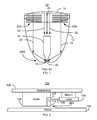
- FIG. 1depicts a portion of a conventional energy assisted magnetic recording (EAMR) transducer 10 .
- the conventional EAMR transducer 10is used in writing a recording media (not shown in FIG. 1 ) and receives light, or energy, from a conventional laser (not shown in FIG. 1 ).
- the conventional EAMR transducer 10includes gratings 32 A and 32 B, a conventional waveguide 12 , conventional pole 30 , and near-field transducer (NFT) 40 .
- the conventional EAMR transducer 10is shown with a laser spot 14 that is guided by the conventional waveguide 12 to a smaller spot 16 near the air-bearing surface (ABS).
- the light at the smaller spot 16is focused by the NFT 40 to magnetic recording media (not shown), such as a disk.
- Other components that may be part of the conventional EAMR transducer 10are not shown.
- light from the spot 14is coupled to the conventional EAMR transducer 10 using the gratings 32 A and 32 B.
- the waveguide 12which is shown as a planar solid immersion mirror, directs light from the gratings 32 A and 32 B to the spot 16 .
- the conventional wave guidescould take other forms, such as tapered waveguide that directs light toward the spot 16 .
- the direction of travel of the light as directed by the conventional waveguide 12can be seen by the arrows 18 and 20 .
- a small region of the conventional mediais heated by the spot 16 .
- the conventional EAMR transducer 10magnetically writes data to the heated region of the recording media by energizing the conventional pole 30 .
- the conventional EAMR transducer 10may function, there are drawbacks.
- Design of the conventional EAMR transducer 1eeks to balance various considerations.
- the NFT 16 and the pole 30are to be separated by a particular distance.
- thermal protrusionmay affect the spacing between and efficacy of components in the EAMR transducer 10 . This thermal protrusion may be desired to be accounted for.
- the waveguide 12is desired to have a high efficiency to adequately couple light from the laser (not shown in FIG. 1 ) to the conventional NFT 16 . Often, these are competing considerations. Consequently, design of an EAMR transducer is desired to balance these competing considerations.
- the conventional EAMR transducer 10may not appropriately account for these factors. More specifically, the pole 30 , NFT 16 , and waveguide 12 may not provide the desired combination of optical energy and magnetic field to the media. Consequently, performance of the conventional EAMR transducer may suffer.
- a method and system for providing an energy assisted magnetic recording (EAMR) transducer coupled with a laserare described.
- the EAMR transducerhas an air-bearing surface (ABS) configured to reside in proximity to a media during use.
- the method and systeminclude providing at least one waveguide, a near-field transducer (NFT), at least one write pole, and at least one coil.
- the waveguide(s)are for directing the energy from the laser toward the ABS.
- the NFTis coupled with the waveguide and focuses the energy onto the media.
- the write pole(s)includes a stitch for providing a magnetic field to the media and a yoke coupled to the stitch.
- the stitchincludes an ABS-facing surface, a sloped surface, and a NFT-facing surface between the ABS-facing surface and the sloped surface.
- the NFT-facing surfaceis substantially parallel to the NFT.
- the sloped surfaceis sloped at an angle of at least twenty-five degrees and not more than sixty-five degrees with respect to the NFT-facing surface.
- the coil(s)are for energizing the at least one write pole.
- FIG. 1depicts a side view of a conventional EAMR transducer.
- FIG. 2depicts an exemplary embodiment of a portion of an EAMR disk drive.
- FIG. 3depicts a side view of an exemplary embodiment of a portion of an EAMR head.
- FIG. 4depicts side and top views of an exemplary embodiment of a portion of an EAMR transducer.
- FIG. 5depicts a side view of another exemplary embodiment of a portion of an EAMR transducer.
- FIG. 6depicts a side view of another exemplary embodiment of a portion of an EAMR transducer.
- FIG. 7depicts a side view of another exemplary embodiment of a portion of an EAMR transducer.
- FIG. 8depicts an exemplary embodiment of a method of forming a portion of an EAMR transducer.
- FIG. 9depicts an exemplary embodiment of another method of forming a portion of an EAMR transducer.
- FIG. 2is a diagram depicting a portion of an EAMR disk drive 100 .
- FIG. 2is not to scale. For simplicity not all portions of the EAMR disk drive 100 are shown.
- the EAMR disk drive 100includes media 102 , at least one laser 104 , a slider 106 , suspension 108 , and at least one EAMR head 110 including one or more gratings 107 .
- the laser 104is a laser diode.
- the EAMR head 110is coupled with the laser 104 .
- the EAMR transduceris optically coupled to the laser 104 through the grating 107 .
- line 109represents electromagnetic energy (e.g. light) provided from the laser 104 to the grating(s) 107 .
- the laser 104is shown as separately mounted to the suspension 108 , in other embodiments, the laser 104 may be mounted elsewhere.
- the laser 104may be mounted on the slider 106 or otherwise affixed in the EAMR disk drive 100 .
- the EAMR head 110includes at least one waveguide (not explicitly shown in FIG. 2 ), at least one write pole (not explicitly shown in FIG. 2 ), at least one coil (not explicitly shown in FIG. 2 ), and at least one NFT (not explicitly shown in FIG. 2 ).
- the EAMR head 110also has an ABS configured to reside in proximity to a media 102 during use.
- the waveguide(s)are for directing the energy from the laser 104 toward the ABS. In the embodiment shown, the energy from the laser 104 is thus coupled into the head 110 , and thus the waveguide(s), by the grating(s) 107 .
- the energy from the laser 104then passes to the NFT, which focuses the energy to heat a small portion of the media 102 .
- the write poleincludes a stitch that has an angled surface configured as described below. The coil is used to energize the pole(s) during writing.
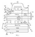
- FIG. 3depicts a side view of an exemplary embodiment of a portion of an EAMR head 110 ′.
- the EAMR head 110 ′may thus be used in the EAMR disk drive 100 .
- FIG. 3is not to scale.
- the head 110 ′is depicted in the context of particular components other and/or different components may be used.
- the EAMR head 110 ′has an ABS configured to reside in proximity to the media 102 during use of the head 110 ′.
- the EAMR head 110 ′ shownis a merged head including a read transducer 111 and an EAMR write transducer 116 .
- the read transducer 111 shownincludes shields 112 and 116 and sensor 114 . However, in another embodiment, another read transducer may be used.
- the EAMR head 110could simply include the EAMR transducer 116 .
- the EAMR transducer 116includes an NFT 118 and a write pole 130 having yoke 132 and a stitch 140 .
- the NFT 118might be replaced with an analogous component.
- the EAMR transduceralso includes return pole 134 with a pedestal 136 , a back pedestal 138 , waveguide 120 and coils 150 and 152 .
- the coils 150 and 152are for energizing the pole 130 .
- the coils 150 and 152might be helical, or pancake, coils.
- the coils 152 and 154may have a different configuration.
- two turnsare shown for each coil 150 and 152 , another number of turns might be used. Further, another number of layers of coils might be used.
- the waveguide 120directs energy toward the NFT 118 and, therefore, the ABS.
- the waveguide 120includes a mirror 122 , cladding 124 and 128 , as well as a core 126 .
- the waveguide 120may include other and/or different components.
- the waveguide 120is a parabolic solid immersion mirror. However, in other embodiments, other configurations may be used for the waveguide 120 .
- the EAMR transducer 116includes the back pedestal 138 and the return pole 134 having the pedestal 136 .
- the back pedestal 138may block a central portion of the beam of energy directed by the waveguide 120 .
- portions of the back pedestal 138 blocking the central portion of the lightare shown by dashed lines.
- the back pedestal 138might includes one or more aperture(s) through which a portion of the waveguide 120 would pass.
- energy from the laser 104might be more directly delivered to the ABS.
- the waveguide 120may then bend around the back pedestal 138 or otherwise be configured to miss the back pedestal 138 .
- the write pole 130includes stitch 140 that is magnetically and physically coupled with the yoke 132 .
- the yoke 132is coupled with the return pole 134 through the back pedestal 138 .
- the stitch 140includes an ABS-facing surface 142 , an NFT-facing surface 144 , a sloped surface 146 , and a back surface 148 .
- the back surface 148may be omitted.
- the sloped surface 146is sloped at an angle, ⁇ , with respect to the NFT-facing surface 144 .
- the angle ⁇is greater than zero degrees and less than ninety degrees. In some embodiments, ⁇ is at least twenty-five degrees and not more than sixty-five degrees.
- ⁇is at least forty degrees and not more than fifty degrees. Because of the sloped surface 146 , the bottom surface of the write pole 130 is further from the core 126 of the waveguide 120 . In some embodiments, for example, the back edge of the sloped surface 146 , where the sloped surface 146 meets the back surface 148 in FIG. 3 , is at least four hundred nanometers from the core 126 .
- the NFT-facing surface 144is substantially parallel to the top surface of the NFT 118 or analogous component. In the embodiment shown, the NFT-facing surface 144 extends in a direction substantially perpendicular to the ABS. As a result, the distance between the NFT 118 and the stitch 140 remains substantially constant along the NFT-facing surface 144 . In some embodiments, the NFT-facing surface 144 extends at least fifty and not more than two hundred nanometers from the ABS.
- the EAMR transducer 116may have improved performance.
- the amount of magnetic material from the poles 130 and 134 in proximity to the waveguide 120is reduced.
- the sloped surface 146 of the stitch 140rises away from the waveguide 120 by the angle ⁇ .
- the amount of magnetic material from the stitch 140 and yoke 132 in proximity to the core 126 of the waveguide 120is reduced.
- the return pole 134is distal from the waveguide 120 . Consequently, adverse affects on the optical efficiency of the magnetic material for the pole 130 and 134 may be reduced.
- Optical efficiency of the EAMR transducer 116may be improved.
- the stitch 140 and pedestal 136are closer to the waveguide 120 in the region of the ABS.
- the NFT-facing surface 144 of the stitch 140may be close to the NFT 118 .
- the NFT-facing surface 144is substantially parallel to the NFT 118 . Consequently, the spacing between the NFT 118 and the pole 130 /stitch 140 is small and controlled. Thus, a higher field may be achieved close to the NFT 118 .
- the magnetic track widthis determined by the region heated by NFT 118 .
- the magnetic track widthis determined by the NFT 118 , rather than the width of the write pole 130 .
- the stitch 140may thus have relaxed size and manufacturing tolerances. Further, the use of the stitch 140 may enhance flux propagation to the media. Similarly, the pedestal 136 , which is coupled with the return pole 134 , allows for magnetic material to be closer to the ABS and the waveguide 120 . A magnetic field sufficient for writing may be provided at the media 102 in the location of the thermal spot developed by the NFT 118 . The EAMR head 110 ′ may, therefore, have improved magnetic performance.
- the sloped surface 146allows for a balancing of optical and magnetic efficiencies.
- the sloped surface 146has a sufficiently large 8 that magnetic material is moved further from the waveguide core 126 .
- optical efficiencymay be improved.
- the angle ⁇is sufficiently small that enough magnetic field is provided to the media 102 in the region of the spot heated by the NFT 118 that the magnetic efficiency of the write pole 130 is not unduly sacrificed. As a result, the combination of the magnetic and optical efficiencies may be enhanced.
- the stitch 140is configured to choke flux off from being delivered to the media after a particular write current is reached.
- the write field produced by the pole 130is relatively constant for write currents in excess of this particular write current. This feature may allow for a higher data rate and reduced adjacent track interference. Consequently, drive optimization may be facilitated.
- the pedestal 136may also enhance the field at the media 102 . This effect may have particular utility if the media 102 does not contain a soft underlayer.
- the pedestal 136may be is tens of microns wide in the cross track direction (perpendicular to the page in FIG. 3 ).
- the pedestal throat height, tmay also be optimized to increase the magnetic field in the media 102 .
- the gap between the pedestal 136 and the pole 130is also reduced by extending the pedestal 136 to just below the waveguide 120 . As a result the pedestal 136 is tall enough to include the coil 152 .
- a parabolic solid immersion mirrormay be used for the waveguide 120 .
- the back pedestal 138passes through the waveguide 120 .
- the center of the beam of energy from the laser 104is blocked.
- the center of the beamgenerally does not interact with the mirrored sides of a parabolic solid immersion mirror.
- a parabolic solid immersion mirrordoes not focus the beam center.
- the width of the yoke 132is narrow enough to reduce interference with light propagation through a parabolic solid immersion mirror 120 .
- substantially no adverse affectsresult from the narrow back pedestal 138 passing through the waveguide/parabolic solid immersion mirror 120 .
- the blocking caused by the yoke 132may result in a smaller, focused beam spot at the NFT 118 and ABS.
- a mirror(not shown) may be positioned behind the yoke 132 and/or back pedestal 138 to decrease light absorption and heating in the yoke 132 .
- Coils 150 and 152are used. Although described as two separate coils, the coils 150 and 152 may be two layers of a single coil. The pancake coils 152 and 154 generally do not interfere with the beam of energy near the pole 130 . The pancake coils 152 and 154 are also generally efficient in coupling to the yoke 132 .
- the two turn configuration shown in FIG. 3may have a high frequency response because of low inductance and resistance. However, in other embodiments, another number of turns, such as a three turn configuration, may be used to increase the field at the pole 130 versus the write current used.
- the coils 150 and 152are thus configured to improve performance of the head 110 ′.
- the thickness of the pole 130may be adjusted to improve performance.
- a thinner pole 130may cause a slight enhancement to the field magnitude.
- Such an embodimentmay also decreases the number of tracks exposed to the trailing edge field when the head 110 ′ is at skew.
- various features of the EAMR head 110 ′may be used to improve overall performance of the EAMR head 110 ′, for example by balancing optical and magnetic considerations.
- FIG. 4depicts side and top views of an exemplary embodiment of a portion of an EAMR transducer 116 ′.
- the pole 130 ′, the stitch 140 ′ and NFT 118 ′are shown.
- FIG. 4is not to scale. For simplicity not all portions of the EAMR transducer 116 ′ are shown.
- the EAMR transducer 116 ′is depicted in the context of particular components other and/or different components may be used. Referring to FIGS. 2-4 , the EAMR transducer 116 ′ is analogous to the EAMR transducer and may be used in the disk drive 100 .
- the EAMR transducer 116 ′has an ABS configured to reside in proximity to the media 102 during use of the head 110 ′.
- the EAMR transducer 116 ′may be used in the EAMR head 110 and/or 110 ′.
- the EAMR transducer 116 ′includes components that are analogous to those of the EAMR transducer 116 depicted in FIG. 3 .
- the EAMR transducer 116 ′includes a stitch 140 ′ and an NFT 118 ′.
- the stitch 140 ′thus includes an ABS-facing surface 142 ′, an NFT-facing surface 144 ′, a sloped surface 146 ′, and a back surface 148 ′ corresponding to the ABS-facing surface 142 , the NFT-facing surface 144 , the sloped surface 146 , and the back surface 148 , respectively.
- the sloped surface 146 ′thus slopes at an angle ⁇ ′ corresponding to the angle ⁇ .
- the EAMR transducer 116 ′may share the benefits of the EAMR transducer 116 .
- the EAMR transducer 116 ′may include a connecting layer 170 .
- the connecting layer 170includes one or more nonmagnetic materials. As can be seen in FIG. 4 , the connecting layer 170 resides between the NFT 118 ′ and the stitch 140 ′ of the write pole 130 ′.
- the nonmagnetic connecting material(s)have high thermal conductivities.
- the connecting layer 170may thus thermally couple the NFT 118 ′ with the stitch 140 ′.
- the pole 130 ′may thus act as a heat sink for the NFT 118 ′. Consequently, the temperature of the NFT 118 ′ may be reduced. As a result, performance of the EAMR transducer 116 ′ may be improved.
- the stitch 140 ′may include a nose 143 and a flared region 145 .
- the nose 143 and the flared region 145meet at the flare point 149 .
- the flare point 149may be at least fifty and not more than two hundred nanometers from the ABS.
- the NFT-facing 144 ′ surfacediverges from the NFT 118 ′ at its back edge, where the NFT-facing surface 144 ′ meets the sloped surface 146 ′.
- the throat height, THis the distance from the ABS to the back edge of the NFT-facing surface 144 ′. In some embodiments, the throat height is at least fifty and not more than two hundred nanometers.
- the flare point 149is the same as the throat height. However, in other embodiments, the throat height and flare point 149 differ. Thus, the throat height and flare point 149 may also be configured to enhance performance of the EAMR transducer 116 ′.
- FIG. 5depicts a side view of another exemplary embodiment of a portion of an EAMR transducer 116 ′′.
- the pole 130 ′, the stitch 140 ′, yoke 132 ′, and NFT 118 ′′are shown.
- FIG. 5is not to scale. For simplicity not all portions of the EAMR transducer 116 ′′ are shown.
- the EAMR transducer 116 ′′is depicted in the context of particular components other and/or different components may be used. Referring to FIGS. 2-5 , the EAMR transducer 116 ′′ is analogous to the EAMR transducers 116 / 116 ′ and may be used in the EAMR disk drive 100 .
- the transducer 116 ′′has an ABS configured to reside in proximity to the media 102 during use of the head 110 / 110 ′.
- the EAMR transducer 116 ′′may be used in the EAMR head 110 / 110 ′.
- the EAMR transducer 116 ′′may include components that are analogous to those of the EAMR transducers 116 and 116 ′.
- the EAMR transducer 116 ′′includes a stitch 140 ′′, yoke 132 ′, and an NFT 118 ′′.
- the stitch 140 ′′includes an ABS-facing surface 142 ′′, an NFT-facing surface 144 ′′, a sloped surface 146 ′′, and a back surface 148 ′′ corresponding to the ABS-facing surface 142 / 142 ′, the NFT-facing surface 144 / 144 ′, the sloped surface 146 / 146 ′, and the back surface 148 / 148 ′, respectively.
- the sloped surface 146 ′′thus slopes at an angle ⁇ ′′ corresponding to the angle ⁇ / ⁇ ′.
- the EAMR transducer 116 ′may include a connecting layer such as the layer 170 .
- the EAMR transducer 116 ′′may include a nose (not explicitly labeled), a flare point (not explicitly labeled), and a flared region (not explicitly labeled) that are analogous to the nose 143 , the flare point 149 , and the flared region 145 , respectively.
- the EAMR transducer 116 ′′may share the benefits of the EAMR transducers 116 and/or 116 ′.
- the stitch 140 ′′does not have a back surface analogous to the back surfaces 148 / 148 ′. Stated differently, there is no surface substantially parallel to the NFT-facing surface 144 ′ that is both at the leading edge of the stitch 140 ′′ and that is distal from the ABS-facing surface 142 ′′. In another embodiment, the stitch 140 ′′ might have a back surface (not shown) that is not parallel to the NFT-facing surface 144 ′. Thus, in addition to sharing the benefits of the EAMR transducers 116 / 116 ′, the transducers 116 ′′ allows for flexible configuration of the stitch 140 ′′.
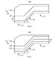
- FIG. 6depicts a side view of another exemplary embodiment of a portion of an EAMR transducer.
- a stitch 200is shown.
- FIG. 6is not to scale.
- the stitch 200is depicted in the context of particular components other and/or different components may be used.
- the stitch 200is analogous to the stitches 140 / 140 ′/ 140 ′′ and may be used EAMR transducers 116 / 116 ′/ 116 ′′, the EAMR heads 110 / 110 ′, and the EAMR disk drive 100 .
- the stitch 200has an ABS-facing surface 212 , an NFT-facing surface 214 , a sloped surface 216 , and an optional back surface 218 .
- the ABS-facing surface 212 , the NFT-facing surface 214 , the sloped surface 216 , and the back surface 218correspond to the ABS-facing surfaces 142 / 142 ′/ 142 ′′, the NFT-facing surfaces 144 / 144 ′/ 144 ′′, the sloped surfaces 146 / 146 ′/ 146 ′′, and the back surfaces 148 / 148 ′, respectively.
- the sloped surface 216forms an angle, ⁇ , with the NFT-facing surface 214 .
- the angle ⁇is analogous to the angles ⁇ / ⁇ ′/ ⁇ ′′.
- a connecting layersuch as the layer 170 may be used.
- the stitch 200may include a nose (not explicitly labeled), a flare point (not explicitly labeled), and a flared region (not explicitly labeled) that are analogous to the nose 143 , the flare point 149 , and the flared region 145 , respectively.
- an EAMR transducer using the stitch 200may share the benefits of the EAMR transducers 116 / 116 ′/ 116 ′′.
- the magnetic moment of the stitch 200varies.
- the stitch 200includes layers 202 , 204 , and 206 .
- the layers 202 , 204 , and 206may have different magnetic moments.
- the layer 202 at the leading edge of the stitch 200has the highest moment.
- the moments of the layers 202 , 204 , and 206decrease with increasing distance from the leading edge.
- the layer 204may have a higher moment than the layer but a lower moment than the layer 202 .
- the layer 206has a lower moment than both layers 202 and 204 .
- the layer 202may be a high moment sputtered material that functions as a seed for subsequent plated layers.
- Layers 204 and 206may be plated and have lower moments than the layer 202 .
- the stitch 200could be formed by a single material having varying moments.
- the composition of an alloymay be varied based on the distance from the leading edge such that the moment decreases with increasing distance from the leading edge.
- the stitch 200has a higher moment in proximity to an NFT (not shown in FIG. 6 ).
- the higher moment layer 202is closest to the portion of the media (not shown) currently being written.
- the layers 204 and 206 closer to the trailing edge of the pole using the stitch 200have lower moments. This feature may decrease the magnetic field at the trailing edge of the pole. The trailing edge field is thus less likely to affect previously written tracks that are either on track or on adjacent tracks. Consequently, adjacent track interference that degrades previously written tracks may be reduced. Consequently, performance of the EAMR transducer using the stitch 200 may be further enhanced.
- FIG. 7depicts a side view of another exemplary embodiment of an EAMR transducer.
- a stitch 200 ′is shown.
- FIG. 7is not to scale.
- the stitch 200 ′is depicted in the context of particular components other and/or different components may be used. Referring to FIGS.
- the stitch 200 ′is analogous to the stitches 140 / 140 ′/ 140 ′′/ 200 and may be used EAMR transducers 116 / 116 ′/ 116 ′′, the EAMR heads 110 / 110 ′, and the EAMR disk drive 100 .
- the stitch 200 ′has an ABS-facing surface 212 ′, an NFT-facing surface 214 ′, a sloped surface 216 ′, and an optional back surface 218 ′.
- the ABS-facing surface 212 ′, the NFT-facing surface 214 ′, the sloped surface 216 ′, and the back surface 218 ′correspond to the ABS-facing surfaces 142 / 142 ′/ 142 ′′/ 212 , the NFT-facing surfaces 144 / 144 ′/ 144 ′′/ 214 , the sloped surfaces 146 / 146 ′/ 146 ′′/ 215 , and the back surfaces 148 / 148 ′/ 218 , respectively.
- the sloped surface 216 ′forms an angle, ⁇ ′, with the NFT-facing surface 214 ′.
- the angle ⁇ ′is analogous to the angles ⁇ / ⁇ ′/ ⁇ ′′/ ⁇ .
- a connecting layersuch as the layer 170 may be used.
- the stitch 200 ′may include a nose (not explicitly labeled), a flare point (not explicitly labeled), and a flared region (not explicitly labeled) that are analogous to the nose 143 , the flare point 149 , and the flared region 145 , respectively.
- an EAMR transducer using the stitch 200 ′may share the benefits of the EAMR transducers 116 / 116 ′/ 116 ′′/ 200 .
- the stitch 200 ′also includes layer 208 .
- the layers 202 ′, 204 ′, 206 ′, and 208may have different magnetic moments.
- the layer 202 ′ at the leading edge of the stitch 200 ′has the highest moment.
- the moments of the layers 202 ′, 204 ′, 206 ′ and 208decrease with increasing distance from the leading edge.
- the layer 204 ′may have a higher moment than the layer but a lower moment than the layer 202 ′.
- the layer 206 ′has a lower moment than layer 204 ′ but higher than layer 208 .
- the layer 208may have the lowest moment of all layers 202 ′, 204 ′, 206 ′, and 208 .
- the layer 202may be a high moment sputtered material that functions as a seed for subsequent plated layers 204 , 206 , and 208 .
- the stitch 200 ′shares the benefits of the stitch 200 .
- the magnetic field from the stitch 200 ′may be more concentrated in proximity to an NFT, near the leading edge of the stitch 200 ′.
- an EAMR transducer using the stitch 200 ′may provide sufficient magnetic field for writing to the media, while being less likely to adversely affect previously written adjacent tracks. Consequently, performance of an EAMR disk drive, EAMR head, and/or EAMR transducer using the stitch 200 ′ may be improved.
- FIG. 8depicts an exemplary embodiment of a method 300 of forming a portion of an EAMR transducer. For simplicity, some steps may be omitted, combined, and/or performed in another sequence.
- the method 300is described in the context of the EAMR transducer 116 ′. However, the method 300 may be used to fabricate other EAMR transducers. In addition, the method 300 is described in the context of fabricating a single transducer 116 ′. However, multiple transducers may be fabricated substantially in parallel.
- the method 300also starts after formation of a portion of the EAMR transducer 116 ′. Other structures may also be fabricated as part of formation of the transducer 116 ′. Further, although described as separate steps, portions of the method 300 may be interleaved as the transducer 116 ′ may be manufactured layer by layer.
- At least one waveguide 120 for directing the energy from the laser 104 toward the ABSis provided, via step 302 .
- Step 302may thus include fabricating the mirror 122 , cladding 124 and 128 , and the core 126 .
- a parabolic solid immersion mirrormight be fabricated in step 302 .
- the NFT 118 ′is provided, via step 304 .
- the NFT 118 ′is optically coupled with the waveguide 120 and is for focusing the energy from the laser onto the media 102 .
- the write pole 130is provided, via step 306 .
- Step 306thus includes fabricating the stitch 140 and the yoke 132 .
- the ABS-facing surface 142 , a sloped surface 146 , and the NFT-facing surface 144 between the ABS-facing surface 142 and the sloped surface 146are formed.
- the back surface 148is also manufactured.
- the coils 150 and 152are also provided, via step 308 . Fabrication of the EAMR transducer 116 ′ may then be completed. Thus, using the method 300 , the benefits of the EAMR transducer 116 ′ may be achieved.
- FIG. 9depicts an exemplary embodiment of another method 310 of forming a portion of an EAMR transducer. For simplicity, some steps may be omitted, combined, and/or performed in another sequence.
- the method 310is described in the context of the EAMR transducer 116 ′ and the stitch 140 / 140 ′/ 140 ′′/ 200 / 200 ′. However, the method 310 may be used to fabricate other EAMR transducers.
- the method 310is described in the context of fabricating a single transducer 116 ′. However, multiple transducers may be fabricated substantially in parallel.
- the method 310also starts after formation of a portion of the EAMR transducer 116 ′. Other structures may also be fabricated as part of formation of the transducer 116 ′. Further, although described as separate steps, portions of the method 310 may be interleaved as the transducer 116 ′ may be manufactured layer by layer.
- At least one waveguide 120 for directing the energy from the laser 104 toward the ABSis provided, via step 312 .
- Step 312is analogous to step 302 .
- the NFT 118 ′is provided, via step 314 .
- Step 314is analogous to step 304 .
- the connecting layer 170may be provided on the NFT 118 / 118 ′, via step 316 .
- the NFT 118 / 118 ′may be thermally coupled to the pole 130 / 130 ′.
- the write pole 130is provided, via step 318 .
- Step 318thus includes fabricating the stitch 140 / 140 ′/ 140 ′′/ 200 / 200 ′ and the yoke 132 / 132 ′/ 132 ′′.
- the remaining magnetic portions of the transducer 116 / 116 ′may be fabricated, via step 320 .
- the poles 130 and 134 , the pedestal 136 , and the back pedestal 138may be formed.
- the benefits of the EAMR transducer 116 ′may be achieved.
Landscapes
- Engineering & Computer Science (AREA)
- Manufacturing & Machinery (AREA)
- Physics & Mathematics (AREA)
- Electromagnetism (AREA)
- Magnetic Heads (AREA)
- Recording Or Reproducing By Magnetic Means (AREA)
Abstract
Description
Claims (28)
Priority Applications (1)
| Application Number | Priority Date | Filing Date | Title |
|---|---|---|---|
| US12/614,341US8164855B1 (en) | 2009-11-06 | 2009-11-06 | Method and system for providing a write pole in an energy assisted magnetic recording disk drive |
Applications Claiming Priority (1)
| Application Number | Priority Date | Filing Date | Title |
|---|---|---|---|
| US12/614,341US8164855B1 (en) | 2009-11-06 | 2009-11-06 | Method and system for providing a write pole in an energy assisted magnetic recording disk drive |
Publications (1)
| Publication Number | Publication Date |
|---|---|
| US8164855B1true US8164855B1 (en) | 2012-04-24 |
Family
ID=45953534
Family Applications (1)
| Application Number | Title | Priority Date | Filing Date |
|---|---|---|---|
| US12/614,341Active2030-09-08US8164855B1 (en) | 2009-11-06 | 2009-11-06 | Method and system for providing a write pole in an energy assisted magnetic recording disk drive |
Country Status (1)
| Country | Link |
|---|---|
| US (1) | US8164855B1 (en) |
Cited By (157)
| Publication number | Priority date | Publication date | Assignee | Title |
|---|---|---|---|---|
| US20100214685A1 (en)* | 2009-02-24 | 2010-08-26 | Seagate Technology Llc | Recording Head For Heat Assisted Magnetic Recording |
| US8310901B1 (en) | 2010-06-09 | 2012-11-13 | Western Digital (Fremont), Llc | Method and system for providing separate write and optical modules in an energy assisted magnetic recording disk drive |
| US8307540B1 (en)* | 2011-03-10 | 2012-11-13 | Western Digital (Fremont), Llc | Method for providing an energy assisted magnetic recording (EAMR) transducer |
| US8320219B1 (en) | 2010-06-15 | 2012-11-27 | Western Digital (Fremont), Llc | Trailing edge optimized near field transducer |
| US8320220B1 (en)* | 2011-10-13 | 2012-11-27 | Western Digital (Fremont), Llc | Method and system for providing an energy assisted magnetic recording disk drive having a non-conformal heat spreader |
| US8351307B1 (en)* | 2010-06-04 | 2013-01-08 | Western Digital (Fremont), Llc | Trailing edge optimized near field transducer having non-rectangular pin cross section |
| US8418353B1 (en)* | 2009-12-23 | 2013-04-16 | Western Digital (Fremont), Llc | Method for providing a plurality of energy assisted magnetic recording EAMR heads |
| US8486286B1 (en) | 2010-12-21 | 2013-07-16 | Western Digital (Fremont), Llc | Method and system for providing an energy assisted magnetic recording writer having an integrated NFT, heat sink, and pole |
| US8526275B1 (en) | 2012-04-27 | 2013-09-03 | Westerni Digital (Fremont), LLC | Systems and methods for dissipating heat from a near-field transducer in an energy assisted magnetic recording assembly |
| US8619512B1 (en) | 2012-06-22 | 2013-12-31 | Western Digital (Fremont), Llc | Stress buffer for near-field transducer in energy assisted magnetic recording and methods for fabricating the same |
| US8634280B1 (en) | 2011-06-21 | 2014-01-21 | Western Digital (Fremont), Llc | Method and system for providing an energy assisted magnetic recording writer having a ring shaped NFT |
| US8721902B1 (en) | 2011-03-11 | 2014-05-13 | Western Digital (Fremont), Llc | Method and system for providing an energy assisted magnetic recording writer having a heat sink and NFT |
| US8830628B1 (en) | 2009-02-23 | 2014-09-09 | Western Digital (Fremont), Llc | Method and system for providing a perpendicular magnetic recording head |
| US8834728B1 (en) | 2011-03-10 | 2014-09-16 | Western Digital (Fremont), Llc | Method and system for providing an energy assisted magnetic recording writer having a self aligned heat sink and NFT |
| US20140269234A1 (en)* | 2013-03-15 | 2014-09-18 | Seagate Technology Llc | Write head core |
| US8879207B1 (en) | 2011-12-20 | 2014-11-04 | Western Digital (Fremont), Llc | Method for providing a side shield for a magnetic recording transducer using an air bridge |
| US8883017B1 (en) | 2013-03-12 | 2014-11-11 | Western Digital (Fremont), Llc | Method and system for providing a read transducer having seamless interfaces |
| US8891205B2 (en)* | 2013-04-16 | 2014-11-18 | Seagate Technology Llc | Apparatuses and methods for controlling near-field transducer to write pole spacing |
| US8917581B1 (en) | 2013-12-18 | 2014-12-23 | Western Digital Technologies, Inc. | Self-anneal process for a near field transducer and chimney in a hard disk drive assembly |
| US8923102B1 (en) | 2013-07-16 | 2014-12-30 | Western Digital (Fremont), Llc | Optical grating coupling for interferometric waveguides in heat assisted magnetic recording heads |
| US8947985B1 (en) | 2013-07-16 | 2015-02-03 | Western Digital (Fremont), Llc | Heat assisted magnetic recording transducers having a recessed pole |
| GB2516754A (en)* | 2013-06-11 | 2015-02-04 | HGST Netherlands BV | Magnetic head providing write protrusion suppression and methods of formation thereof |
| US8953422B1 (en) | 2014-06-10 | 2015-02-10 | Western Digital (Fremont), Llc | Near field transducer using dielectric waveguide core with fine ridge feature |
| US8958272B1 (en) | 2014-06-10 | 2015-02-17 | Western Digital (Fremont), Llc | Interfering near field transducer for energy assisted magnetic recording |
| US8970988B1 (en) | 2013-12-31 | 2015-03-03 | Western Digital (Fremont), Llc | Electric gaps and method for making electric gaps for multiple sensor arrays |
| US8971160B1 (en) | 2013-12-19 | 2015-03-03 | Western Digital (Fremont), Llc | Near field transducer with high refractive index pin for heat assisted magnetic recording |
| US8976635B1 (en) | 2014-06-10 | 2015-03-10 | Western Digital (Fremont), Llc | Near field transducer driven by a transverse electric waveguide for energy assisted magnetic recording |
| US8982508B1 (en) | 2011-10-31 | 2015-03-17 | Western Digital (Fremont), Llc | Method for providing a side shield for a magnetic recording transducer |
| US8980109B1 (en) | 2012-12-11 | 2015-03-17 | Western Digital (Fremont), Llc | Method for providing a magnetic recording transducer using a combined main pole and side shield CMP for a wraparound shield scheme |
| US8984740B1 (en) | 2012-11-30 | 2015-03-24 | Western Digital (Fremont), Llc | Process for providing a magnetic recording transducer having a smooth magnetic seed layer |
| US8988825B1 (en) | 2014-02-28 | 2015-03-24 | Western Digital (Fremont, LLC | Method for fabricating a magnetic writer having half-side shields |
| US8988812B1 (en) | 2013-11-27 | 2015-03-24 | Western Digital (Fremont), Llc | Multi-sensor array configuration for a two-dimensional magnetic recording (TDMR) operation |
| US8995087B1 (en) | 2006-11-29 | 2015-03-31 | Western Digital (Fremont), Llc | Perpendicular magnetic recording write head having a wrap around shield |
| US8993217B1 (en) | 2013-04-04 | 2015-03-31 | Western Digital (Fremont), Llc | Double exposure technique for high resolution disk imaging |
| US9001467B1 (en) | 2014-03-05 | 2015-04-07 | Western Digital (Fremont), Llc | Method for fabricating side shields in a magnetic writer |
| US9001628B1 (en) | 2013-12-16 | 2015-04-07 | Western Digital (Fremont), Llc | Assistant waveguides for evaluating main waveguide coupling efficiency and diode laser alignment tolerances for hard disk |
| US8997832B1 (en) | 2010-11-23 | 2015-04-07 | Western Digital (Fremont), Llc | Method of fabricating micrometer scale components |
| US9007719B1 (en) | 2013-10-23 | 2015-04-14 | Western Digital (Fremont), Llc | Systems and methods for using double mask techniques to achieve very small features |
| US9007725B1 (en) | 2014-10-07 | 2015-04-14 | Western Digital (Fremont), Llc | Sensor with positive coupling between dual ferromagnetic free layer laminates |
| US9007879B1 (en) | 2014-06-10 | 2015-04-14 | Western Digital (Fremont), Llc | Interfering near field transducer having a wide metal bar feature for energy assisted magnetic recording |
| US9013836B1 (en) | 2013-04-02 | 2015-04-21 | Western Digital (Fremont), Llc | Method and system for providing an antiferromagnetically coupled return pole |
| US9042052B1 (en) | 2014-06-23 | 2015-05-26 | Western Digital (Fremont), Llc | Magnetic writer having a partially shunted coil |
| US9042051B2 (en) | 2013-08-15 | 2015-05-26 | Western Digital (Fremont), Llc | Gradient write gap for perpendicular magnetic recording writer |
| US9042058B1 (en) | 2013-10-17 | 2015-05-26 | Western Digital Technologies, Inc. | Shield designed for middle shields in a multiple sensor array |
| US9042057B1 (en) | 2013-01-09 | 2015-05-26 | Western Digital (Fremont), Llc | Methods for providing magnetic storage elements with high magneto-resistance using Heusler alloys |
| US9042208B1 (en) | 2013-03-11 | 2015-05-26 | Western Digital Technologies, Inc. | Disk drive measuring fly height by applying a bias voltage to an electrically insulated write component of a head |
| US9053735B1 (en) | 2014-06-20 | 2015-06-09 | Western Digital (Fremont), Llc | Method for fabricating a magnetic writer using a full-film metal planarization |
| US9065043B1 (en) | 2012-06-29 | 2015-06-23 | Western Digital (Fremont), Llc | Tunnel magnetoresistance read head with narrow shield-to-shield spacing |
| US9064528B1 (en) | 2013-05-17 | 2015-06-23 | Western Digital Technologies, Inc. | Interferometric waveguide usable in shingled heat assisted magnetic recording in the absence of a near-field transducer |
| US9064527B1 (en) | 2013-04-12 | 2015-06-23 | Western Digital (Fremont), Llc | High order tapered waveguide for use in a heat assisted magnetic recording head |
| US9064507B1 (en) | 2009-07-31 | 2015-06-23 | Western Digital (Fremont), Llc | Magnetic etch-stop layer for magnetoresistive read heads |
| US9070381B1 (en) | 2013-04-12 | 2015-06-30 | Western Digital (Fremont), Llc | Magnetic recording read transducer having a laminated free layer |
| US9082423B1 (en) | 2013-12-18 | 2015-07-14 | Western Digital (Fremont), Llc | Magnetic recording write transducer having an improved trailing surface profile |
| US9087534B1 (en) | 2011-12-20 | 2015-07-21 | Western Digital (Fremont), Llc | Method and system for providing a read transducer having soft and hard magnetic bias structures |
| US9087527B1 (en) | 2014-10-28 | 2015-07-21 | Western Digital (Fremont), Llc | Apparatus and method for middle shield connection in magnetic recording transducers |
| US9093639B2 (en) | 2012-02-21 | 2015-07-28 | Western Digital (Fremont), Llc | Methods for manufacturing a magnetoresistive structure utilizing heating and cooling |
| US9104107B1 (en) | 2013-04-03 | 2015-08-11 | Western Digital (Fremont), Llc | DUV photoresist process |
| US9111564B1 (en) | 2013-04-02 | 2015-08-18 | Western Digital (Fremont), Llc | Magnetic recording writer having a main pole with multiple flare angles |
| US9111550B1 (en) | 2014-12-04 | 2015-08-18 | Western Digital (Fremont), Llc | Write transducer having a magnetic buffer layer spaced between a side shield and a write pole by non-magnetic layers |
| US9111558B1 (en) | 2014-03-14 | 2015-08-18 | Western Digital (Fremont), Llc | System and method of diffractive focusing of light in a waveguide |
| US9123362B1 (en) | 2011-03-22 | 2015-09-01 | Western Digital (Fremont), Llc | Methods for assembling an electrically assisted magnetic recording (EAMR) head |
| US9123359B1 (en) | 2010-12-22 | 2015-09-01 | Western Digital (Fremont), Llc | Magnetic recording transducer with sputtered antiferromagnetic coupling trilayer between plated ferromagnetic shields and method of fabrication |
| US9123358B1 (en) | 2012-06-11 | 2015-09-01 | Western Digital (Fremont), Llc | Conformal high moment side shield seed layer for perpendicular magnetic recording writer |
| US9123374B1 (en) | 2015-02-12 | 2015-09-01 | Western Digital (Fremont), Llc | Heat assisted magnetic recording writer having an integrated polarization rotation plate |
| US9135930B1 (en) | 2014-03-06 | 2015-09-15 | Western Digital (Fremont), Llc | Method for fabricating a magnetic write pole using vacuum deposition |
| US9135942B2 (en) | 2013-05-28 | 2015-09-15 | HGST Netherlands B.V. | Heat assisted magnetic recording head having wider heat sink and pole |
| US9135937B1 (en) | 2014-05-09 | 2015-09-15 | Western Digital (Fremont), Llc | Current modulation on laser diode for energy assisted magnetic recording transducer |
| US9142233B1 (en) | 2014-02-28 | 2015-09-22 | Western Digital (Fremont), Llc | Heat assisted magnetic recording writer having a recessed pole |
| US9147408B1 (en) | 2013-12-19 | 2015-09-29 | Western Digital (Fremont), Llc | Heated AFM layer deposition and cooling process for TMR magnetic recording sensor with high pinning field |
| US9147404B1 (en) | 2015-03-31 | 2015-09-29 | Western Digital (Fremont), Llc | Method and system for providing a read transducer having a dual free layer |
| US9153255B1 (en) | 2014-03-05 | 2015-10-06 | Western Digital (Fremont), Llc | Method for fabricating a magnetic writer having an asymmetric gap and shields |
| US9183856B1 (en)* | 2014-10-31 | 2015-11-10 | HGST Netherlands B.V. | System and method for integration of magnetic lip and near field transducer in heat assisted magnetic recording write heads |
| US9183854B2 (en) | 2014-02-24 | 2015-11-10 | Western Digital (Fremont), Llc | Method to make interferometric taper waveguide for HAMR light delivery |
| US9190085B1 (en) | 2014-03-12 | 2015-11-17 | Western Digital (Fremont), Llc | Waveguide with reflective grating for localized energy intensity |
| US9190079B1 (en) | 2014-09-22 | 2015-11-17 | Western Digital (Fremont), Llc | Magnetic write pole having engineered radius of curvature and chisel angle profiles |
| US9194692B1 (en) | 2013-12-06 | 2015-11-24 | Western Digital (Fremont), Llc | Systems and methods for using white light interferometry to measure undercut of a bi-layer structure |
| US9196269B2 (en) | 2014-02-18 | 2015-11-24 | Seagate Technology Llc | Heat sink layer along an aperture of a near-field transducer |
| US9202480B2 (en) | 2009-10-14 | 2015-12-01 | Western Digital (Fremont), LLC. | Double patterning hard mask for damascene perpendicular magnetic recording (PMR) writer |
| US9202493B1 (en) | 2014-02-28 | 2015-12-01 | Western Digital (Fremont), Llc | Method of making an ultra-sharp tip mode converter for a HAMR head |
| US9214172B2 (en) | 2013-10-23 | 2015-12-15 | Western Digital (Fremont), Llc | Method of manufacturing a magnetic read head |
| US9213322B1 (en) | 2012-08-16 | 2015-12-15 | Western Digital (Fremont), Llc | Methods for providing run to run process control using a dynamic tuner |
| US9214165B1 (en) | 2014-12-18 | 2015-12-15 | Western Digital (Fremont), Llc | Magnetic writer having a gradient in saturation magnetization of the shields |
| US9214169B1 (en) | 2014-06-20 | 2015-12-15 | Western Digital (Fremont), Llc | Magnetic recording read transducer having a laminated free layer |
| US9230565B1 (en) | 2014-06-24 | 2016-01-05 | Western Digital (Fremont), Llc | Magnetic shield for magnetic recording head |
| US9236560B1 (en) | 2014-12-08 | 2016-01-12 | Western Digital (Fremont), Llc | Spin transfer torque tunneling magnetoresistive device having a laminated free layer with perpendicular magnetic anisotropy |
| US9245543B1 (en) | 2010-06-25 | 2016-01-26 | Western Digital (Fremont), Llc | Method for providing an energy assisted magnetic recording head having a laser integrally mounted to the slider |
| US9245562B1 (en) | 2015-03-30 | 2016-01-26 | Western Digital (Fremont), Llc | Magnetic recording writer with a composite main pole |
| US9245545B1 (en) | 2013-04-12 | 2016-01-26 | Wester Digital (Fremont), Llc | Short yoke length coils for magnetic heads in disk drives |
| US9251813B1 (en) | 2009-04-19 | 2016-02-02 | Western Digital (Fremont), Llc | Method of making a magnetic recording head |
| US9263071B1 (en) | 2015-03-31 | 2016-02-16 | Western Digital (Fremont), Llc | Flat NFT for heat assisted magnetic recording |
| US9263067B1 (en) | 2013-05-29 | 2016-02-16 | Western Digital (Fremont), Llc | Process for making PMR writer with constant side wall angle |
| US9269382B1 (en) | 2012-06-29 | 2016-02-23 | Western Digital (Fremont), Llc | Method and system for providing a read transducer having improved pinning of the pinned layer at higher recording densities |
| US9275657B1 (en) | 2013-08-14 | 2016-03-01 | Western Digital (Fremont), Llc | Process for making PMR writer with non-conformal side gaps |
| US9280990B1 (en) | 2013-12-11 | 2016-03-08 | Western Digital (Fremont), Llc | Method for fabricating a magnetic writer using multiple etches |
| US9287494B1 (en) | 2013-06-28 | 2016-03-15 | Western Digital (Fremont), Llc | Magnetic tunnel junction (MTJ) with a magnesium oxide tunnel barrier |
| US9286919B1 (en) | 2014-12-17 | 2016-03-15 | Western Digital (Fremont), Llc | Magnetic writer having a dual side gap |
| US9305583B1 (en) | 2014-02-18 | 2016-04-05 | Western Digital (Fremont), Llc | Method for fabricating a magnetic writer using multiple etches of damascene materials |
| US9312064B1 (en) | 2015-03-02 | 2016-04-12 | Western Digital (Fremont), Llc | Method to fabricate a magnetic head including ion milling of read gap using dual layer hard mask |
| US9318130B1 (en) | 2013-07-02 | 2016-04-19 | Western Digital (Fremont), Llc | Method to fabricate tunneling magnetic recording heads with extended pinned layer |
| US9336814B1 (en) | 2013-03-12 | 2016-05-10 | Western Digital (Fremont), Llc | Inverse tapered waveguide for use in a heat assisted magnetic recording head |
| US9343087B1 (en) | 2014-12-21 | 2016-05-17 | Western Digital (Fremont), Llc | Method for fabricating a magnetic writer having half shields |
| US9343098B1 (en) | 2013-08-23 | 2016-05-17 | Western Digital (Fremont), Llc | Method for providing a heat assisted magnetic recording transducer having protective pads |
| US9343086B1 (en) | 2013-09-11 | 2016-05-17 | Western Digital (Fremont), Llc | Magnetic recording write transducer having an improved sidewall angle profile |
| US9349394B1 (en) | 2013-10-18 | 2016-05-24 | Western Digital (Fremont), Llc | Method for fabricating a magnetic writer having a gradient side gap |
| US9349392B1 (en) | 2012-05-24 | 2016-05-24 | Western Digital (Fremont), Llc | Methods for improving adhesion on dielectric substrates |
| US9361913B1 (en) | 2013-06-03 | 2016-06-07 | Western Digital (Fremont), Llc | Recording read heads with a multi-layer AFM layer methods and apparatuses |
| US9361914B1 (en) | 2014-06-18 | 2016-06-07 | Western Digital (Fremont), Llc | Magnetic sensor with thin capping layer |
| US9368134B1 (en) | 2010-12-16 | 2016-06-14 | Western Digital (Fremont), Llc | Method and system for providing an antiferromagnetically coupled writer |
| US9384763B1 (en) | 2015-03-26 | 2016-07-05 | Western Digital (Fremont), Llc | Dual free layer magnetic reader having a rear bias structure including a soft bias layer |
| US9384765B1 (en) | 2015-09-24 | 2016-07-05 | Western Digital (Fremont), Llc | Method and system for providing a HAMR writer having improved optical efficiency |
| US9396743B1 (en) | 2014-02-28 | 2016-07-19 | Western Digital (Fremont), Llc | Systems and methods for controlling soft bias thickness for tunnel magnetoresistance readers |
| US9396742B1 (en) | 2012-11-30 | 2016-07-19 | Western Digital (Fremont), Llc | Magnetoresistive sensor for a magnetic storage system read head, and fabrication method thereof |
| US9406331B1 (en) | 2013-06-17 | 2016-08-02 | Western Digital (Fremont), Llc | Method for making ultra-narrow read sensor and read transducer device resulting therefrom |
| US9424866B1 (en) | 2015-09-24 | 2016-08-23 | Western Digital (Fremont), Llc | Heat assisted magnetic recording write apparatus having a dielectric gap |
| US9431047B1 (en) | 2013-05-01 | 2016-08-30 | Western Digital (Fremont), Llc | Method for providing an improved AFM reader shield |
| US9431039B1 (en) | 2013-05-21 | 2016-08-30 | Western Digital (Fremont), Llc | Multiple sensor array usable in two-dimensional magnetic recording |
| US9431038B1 (en) | 2015-06-29 | 2016-08-30 | Western Digital (Fremont), Llc | Method for fabricating a magnetic write pole having an improved sidewall angle profile |
| US9431032B1 (en) | 2013-08-14 | 2016-08-30 | Western Digital (Fremont), Llc | Electrical connection arrangement for a multiple sensor array usable in two-dimensional magnetic recording |
| US9431031B1 (en) | 2015-03-24 | 2016-08-30 | Western Digital (Fremont), Llc | System and method for magnetic transducers having multiple sensors and AFC shields |
| US9437251B1 (en) | 2014-12-22 | 2016-09-06 | Western Digital (Fremont), Llc | Apparatus and method having TDMR reader to reader shunts |
| US9441938B1 (en) | 2013-10-08 | 2016-09-13 | Western Digital (Fremont), Llc | Test structures for measuring near field transducer disc length |
| US9443541B1 (en) | 2015-03-24 | 2016-09-13 | Western Digital (Fremont), Llc | Magnetic writer having a gradient in saturation magnetization of the shields and return pole |
| US9449621B1 (en) | 2015-03-26 | 2016-09-20 | Western Digital (Fremont), Llc | Dual free layer magnetic reader having a rear bias structure having a high aspect ratio |
| US9449625B1 (en) | 2014-12-24 | 2016-09-20 | Western Digital (Fremont), Llc | Heat assisted magnetic recording head having a plurality of diffusion barrier layers |
| US9472216B1 (en) | 2015-09-23 | 2016-10-18 | Western Digital (Fremont), Llc | Differential dual free layer magnetic reader |
| US9484051B1 (en) | 2015-11-09 | 2016-11-01 | The Provost, Fellows, Foundation Scholars and the other members of Board, of the College of the Holy and Undivided Trinity of Queen Elizabeth near Dublin | Method and system for reducing undesirable reflections in a HAMR write apparatus |
| US9508365B1 (en) | 2015-06-24 | 2016-11-29 | Western Digital (Fremont), LLC. | Magnetic reader having a crystal decoupling structure |
| US9508372B1 (en) | 2015-06-03 | 2016-11-29 | Western Digital (Fremont), Llc | Shingle magnetic writer having a low sidewall angle pole |
| US9508363B1 (en) | 2014-06-17 | 2016-11-29 | Western Digital (Fremont), Llc | Method for fabricating a magnetic write pole having a leading edge bevel |
| US9530443B1 (en) | 2015-06-25 | 2016-12-27 | Western Digital (Fremont), Llc | Method for fabricating a magnetic recording device having a high aspect ratio structure |
| US9564150B1 (en) | 2015-11-24 | 2017-02-07 | Western Digital (Fremont), Llc | Magnetic read apparatus having an improved read sensor isolation circuit |
| US9595273B1 (en) | 2015-09-30 | 2017-03-14 | Western Digital (Fremont), Llc | Shingle magnetic writer having nonconformal shields |
| US9646639B2 (en) | 2015-06-26 | 2017-05-09 | Western Digital (Fremont), Llc | Heat assisted magnetic recording writer having integrated polarization rotation waveguides |
| US9666214B1 (en) | 2015-09-23 | 2017-05-30 | Western Digital (Fremont), Llc | Free layer magnetic reader that may have a reduced shield-to-shield spacing |
| US20170194022A1 (en)* | 2016-01-04 | 2017-07-06 | Seagate Technology Llc | Recessed hardmask used to form hamr nft heat sink |
| US9721595B1 (en) | 2014-12-04 | 2017-08-01 | Western Digital (Fremont), Llc | Method for providing a storage device |
| US9741366B1 (en) | 2014-12-18 | 2017-08-22 | Western Digital (Fremont), Llc | Method for fabricating a magnetic writer having a gradient in saturation magnetization of the shields |
| US9740805B1 (en) | 2015-12-01 | 2017-08-22 | Western Digital (Fremont), Llc | Method and system for detecting hotspots for photolithographically-defined devices |
| US9754611B1 (en) | 2015-11-30 | 2017-09-05 | Western Digital (Fremont), Llc | Magnetic recording write apparatus having a stepped conformal trailing shield |
| US9767831B1 (en) | 2015-12-01 | 2017-09-19 | Western Digital (Fremont), Llc | Magnetic writer having convex trailing surface pole and conformal write gap |
| US9786303B1 (en) | 2015-07-08 | 2017-10-10 | Seagate Technology Llc | Layer for reducing magnetic field proximate a near-field transducer |
| US9786301B1 (en) | 2014-12-02 | 2017-10-10 | Western Digital (Fremont), Llc | Apparatuses and methods for providing thin shields in a multiple sensor array |
| US9799351B1 (en) | 2015-11-30 | 2017-10-24 | Western Digital (Fremont), Llc | Short yoke length writer having assist coils |
| US9812155B1 (en) | 2015-11-23 | 2017-11-07 | Western Digital (Fremont), Llc | Method and system for fabricating high junction angle read sensors |
| US9842615B1 (en) | 2015-06-26 | 2017-12-12 | Western Digital (Fremont), Llc | Magnetic reader having a nonmagnetic insertion layer for the pinning layer |
| US9858951B1 (en) | 2015-12-01 | 2018-01-02 | Western Digital (Fremont), Llc | Method for providing a multilayer AFM layer in a read sensor |
| US9881638B1 (en) | 2014-12-17 | 2018-01-30 | Western Digital (Fremont), Llc | Method for providing a near-field transducer (NFT) for a heat assisted magnetic recording (HAMR) device |
| US9934811B1 (en) | 2014-03-07 | 2018-04-03 | Western Digital (Fremont), Llc | Methods for controlling stray fields of magnetic features using magneto-elastic anisotropy |
| US9953670B1 (en) | 2015-11-10 | 2018-04-24 | Western Digital (Fremont), Llc | Method and system for providing a HAMR writer including a multi-mode interference device |
| US10032468B1 (en) | 2015-11-06 | 2018-07-24 | Seagate Technology Llc | Heat-assisted magnetic recording head configured to conduct heat away from slider components to a substrate |
| US10037770B1 (en) | 2015-11-12 | 2018-07-31 | Western Digital (Fremont), Llc | Method for providing a magnetic recording write apparatus having a seamless pole |
| US10074387B1 (en) | 2014-12-21 | 2018-09-11 | Western Digital (Fremont), Llc | Method and system for providing a read transducer having symmetric antiferromagnetically coupled shields |
| US10074386B1 (en)* | 2015-05-19 | 2018-09-11 | Seagate Technology Llc | Magnetic writer coil incorporating integral cooling fins |
| US10360939B2 (en)* | 2017-12-23 | 2019-07-23 | Western Digital Technologies, Inc. | Metal-insulator-metal near-field transducer for heat-assisted magnetic recording |
| US10468058B1 (en)* | 2018-06-28 | 2019-11-05 | Western Digital Technologies, Inc. | Magnetic write head with a tapered return pole |
| US10714128B2 (en) | 2018-10-11 | 2020-07-14 | Western Digital Technologies, Inc. | Magnetic write head with dual return pole |
| US11763842B1 (en)* | 2022-05-12 | 2023-09-19 | Sae Magnetics (H.K.) Ltd. | Method of manufacturing head gimbal assembly, head gimbal assembly and hard disk drive |
Citations (40)
| Publication number | Priority date | Publication date | Assignee | Title |
|---|---|---|---|---|
| US20030128633A1 (en) | 2002-01-08 | 2003-07-10 | Seagate Technology Llc | Heat assisted magnetic recording head with hybrid write pole |
| US20030235121A1 (en) | 2002-06-20 | 2003-12-25 | Seagate Technology Llc | Recording pole for heat assisted magnetic recording |
| US6674594B1 (en) | 1999-07-21 | 2004-01-06 | Hitachi Maxell, Ltd. | Read/write head and magnetic recording device |
| US6714370B2 (en) | 2002-01-07 | 2004-03-30 | Seagate Technology Llc | Write head and method for recording information on a data storage medium |
| US20040081031A1 (en)* | 2002-11-05 | 2004-04-29 | Hideki Saga | Recording head and information recording apparatus |
| WO2004107323A1 (en) | 2003-05-29 | 2004-12-09 | Seagate Technology Llc | Patterned media for heat assisted magnetic recording |
| US20050190682A1 (en)* | 2004-02-26 | 2005-09-01 | Seagate Technology Llc | Head with optical bench for use in data storage devices |
| US6944101B2 (en) | 2002-06-24 | 2005-09-13 | Seagate Technology Llc | Recording pole for delivering coincident heat and magnetic field |
| US6944112B2 (en) | 2002-06-28 | 2005-09-13 | Seagate Technology Llc | Heat assisted magnetic recording head with a planar waveguide |
| US20060083116A1 (en) | 2002-04-18 | 2006-04-20 | Seagate Technology Llc | Heat assisted magnetic recording head with multilayer electromagnetic radiation emission structure |
| US20060133230A1 (en)* | 2004-12-22 | 2006-06-22 | Seagate Technology Llc | Optical recording using a waveguide structure and a phase change medium |
| US7068453B2 (en) | 2004-02-27 | 2006-06-27 | Hitachi Global Storage Technologies Netherlands B.V. | Thermally-assisted perpendicular magnetic recording system and head |
| US20060143635A1 (en) | 2004-12-28 | 2006-06-29 | Sae Magnetics (H.K.) Ltd. | Magnetic thin film head with heat-assisted write section and hard disk drive incorporating same |
| US20060181798A1 (en) | 2005-01-06 | 2006-08-17 | Pioneer Corporation | Magnetic head for use in magnetic recording apparatus |
| US20060187561A1 (en) | 2002-08-23 | 2006-08-24 | Prefix | Holding device for an optical element |
| US7099096B2 (en) | 2003-02-19 | 2006-08-29 | Fuji Xerox Co., Ltd. | Heat-assisted magnetic recording head and heat-assisted magnetic recording apparatus |
| US7106935B2 (en) | 2002-01-07 | 2006-09-12 | Seagate Technology Llc | Apparatus for focusing plasmon waves |
| US7155732B2 (en) | 2003-09-05 | 2006-12-26 | Seagate Technology Llc | Heat assisted magnetic recording head and method |
| US20070070824A1 (en)* | 2005-09-28 | 2007-03-29 | Konica Minolta Holdings, Inc. | Thermal-assisted magnetic recording head and magnetic recording apparatus |
| US20070139818A1 (en) | 2005-12-16 | 2007-06-21 | Tdk Corporation | Thin-film magnetic head with near-field-light-generating layer |
| US20070159718A1 (en) | 2006-01-11 | 2007-07-12 | Samsung Electronics Co., Ltd. | Heat-assisted magnetic recording head and method of manufacturing the same |
| US20070165495A1 (en) | 2006-01-13 | 2007-07-19 | Samsung Electronics Co., Ltd. | Heat assisted magnetic recording head |
| US20070177302A1 (en)* | 2006-01-30 | 2007-08-02 | Tdk Corporation | Thin-film magnetic head having near-field-light-generating portion with trapezoidal end |
| US7268973B2 (en) | 2003-07-24 | 2007-09-11 | Hitachi Global Storage Technologies Netherlands, B.V. | Perpendicular magnetic head having thermally assisted recording element |
| US7272079B2 (en) | 2004-06-23 | 2007-09-18 | Seagate Technology Llc | Transducer for heat assisted magnetic recording |
| US20070230048A1 (en)* | 2006-03-28 | 2007-10-04 | Fujitsu Limited | Magnetic disk device |
| US20080013912A1 (en) | 2006-06-30 | 2008-01-17 | Seagate Technology Llc | Heat-assisted magnetic recording head |
| US20080043360A1 (en) | 2006-08-21 | 2008-02-21 | Tdk Corporation | Thermally assisted magnetic head |
| US20080089187A1 (en) | 2006-10-17 | 2008-04-17 | Samsung Electronics Co., Ltd | Heat-assisted magnetic recording head and recording apparatus including the same |
| US20080144206A1 (en) | 2006-12-18 | 2008-06-19 | Seagate Technology Llc | Data storage apparatus including optically active nano-patterned media and electric field assisted recording method |
| US20080180827A1 (en) | 2007-01-31 | 2008-07-31 | Carnegie Mellon University | Binary anisotropy media |
| US7412143B2 (en)* | 2002-06-28 | 2008-08-12 | Seagate Technology Llc | Heat assisted magnetic recording with heat profile shaping |
| US20080218891A1 (en) | 2007-03-07 | 2008-09-11 | Seagate Technology Llc | Magnetic recording device with an integrated microelectronic device |
| US20080232225A1 (en) | 2007-03-19 | 2008-09-25 | Samsung Electronics Co., Ltd. | 90°-bent metallic waveguide having tapered c-shaped aperture, method of fabricating the waveguide, light delivery module including the waveguide, and heat assisted magnetic recording head having the waveguide |
| US7440660B1 (en) | 2007-10-16 | 2008-10-21 | Seagate Technology Llc | Transducer for heat assisted magnetic recording |
| US20090052092A1 (en) | 2007-08-21 | 2009-02-26 | Headway Technologies, Inc. | Perpendicular magnetic recording head laminated with AFM-FM phase change material |
| US20090073858A1 (en) | 2007-09-19 | 2009-03-19 | Seagate Technology Llc | HAMR Recording Head Having A Sloped Wall Pole |
| US7603480B2 (en)* | 2004-09-16 | 2009-10-13 | Nec Corporation | System using pseudo redundant configurator to switch network devices between operating and standby states |
| US7643248B2 (en)* | 2006-06-30 | 2010-01-05 | Seagate Technology Llc | Optoelectronic emitter mounted on a slider |
| US8023225B2 (en)* | 2007-08-23 | 2011-09-20 | Tdk Corporation | Thermally assisted magnetic head with optical waveguide |
- 2009
- 2009-11-06USUS12/614,341patent/US8164855B1/enactiveActive
Patent Citations (41)
| Publication number | Priority date | Publication date | Assignee | Title |
|---|---|---|---|---|
| US6674594B1 (en) | 1999-07-21 | 2004-01-06 | Hitachi Maxell, Ltd. | Read/write head and magnetic recording device |
| US7106935B2 (en) | 2002-01-07 | 2006-09-12 | Seagate Technology Llc | Apparatus for focusing plasmon waves |
| US6714370B2 (en) | 2002-01-07 | 2004-03-30 | Seagate Technology Llc | Write head and method for recording information on a data storage medium |
| US20030128633A1 (en) | 2002-01-08 | 2003-07-10 | Seagate Technology Llc | Heat assisted magnetic recording head with hybrid write pole |
| US20060083116A1 (en) | 2002-04-18 | 2006-04-20 | Seagate Technology Llc | Heat assisted magnetic recording head with multilayer electromagnetic radiation emission structure |
| US7215629B2 (en) | 2002-06-20 | 2007-05-08 | Seagate Technology Llc | Magnetic recording device for heat assisted magnetic recording |
| US20030235121A1 (en) | 2002-06-20 | 2003-12-25 | Seagate Technology Llc | Recording pole for heat assisted magnetic recording |
| US6944101B2 (en) | 2002-06-24 | 2005-09-13 | Seagate Technology Llc | Recording pole for delivering coincident heat and magnetic field |
| US6944112B2 (en) | 2002-06-28 | 2005-09-13 | Seagate Technology Llc | Heat assisted magnetic recording head with a planar waveguide |
| US7412143B2 (en)* | 2002-06-28 | 2008-08-12 | Seagate Technology Llc | Heat assisted magnetic recording with heat profile shaping |
| US20060187561A1 (en) | 2002-08-23 | 2006-08-24 | Prefix | Holding device for an optical element |
| US20040081031A1 (en)* | 2002-11-05 | 2004-04-29 | Hideki Saga | Recording head and information recording apparatus |
| US7099096B2 (en) | 2003-02-19 | 2006-08-29 | Fuji Xerox Co., Ltd. | Heat-assisted magnetic recording head and heat-assisted magnetic recording apparatus |
| WO2004107323A1 (en) | 2003-05-29 | 2004-12-09 | Seagate Technology Llc | Patterned media for heat assisted magnetic recording |
| US7268973B2 (en) | 2003-07-24 | 2007-09-11 | Hitachi Global Storage Technologies Netherlands, B.V. | Perpendicular magnetic head having thermally assisted recording element |
| US7155732B2 (en) | 2003-09-05 | 2006-12-26 | Seagate Technology Llc | Heat assisted magnetic recording head and method |
| US20050190682A1 (en)* | 2004-02-26 | 2005-09-01 | Seagate Technology Llc | Head with optical bench for use in data storage devices |
| US7068453B2 (en) | 2004-02-27 | 2006-06-27 | Hitachi Global Storage Technologies Netherlands B.V. | Thermally-assisted perpendicular magnetic recording system and head |
| US7272079B2 (en) | 2004-06-23 | 2007-09-18 | Seagate Technology Llc | Transducer for heat assisted magnetic recording |
| US7603480B2 (en)* | 2004-09-16 | 2009-10-13 | Nec Corporation | System using pseudo redundant configurator to switch network devices between operating and standby states |
| US20060133230A1 (en)* | 2004-12-22 | 2006-06-22 | Seagate Technology Llc | Optical recording using a waveguide structure and a phase change medium |
| US20060143635A1 (en) | 2004-12-28 | 2006-06-29 | Sae Magnetics (H.K.) Ltd. | Magnetic thin film head with heat-assisted write section and hard disk drive incorporating same |
| US20060181798A1 (en) | 2005-01-06 | 2006-08-17 | Pioneer Corporation | Magnetic head for use in magnetic recording apparatus |
| US20070070824A1 (en)* | 2005-09-28 | 2007-03-29 | Konica Minolta Holdings, Inc. | Thermal-assisted magnetic recording head and magnetic recording apparatus |
| US20070139818A1 (en) | 2005-12-16 | 2007-06-21 | Tdk Corporation | Thin-film magnetic head with near-field-light-generating layer |
| US20070159718A1 (en) | 2006-01-11 | 2007-07-12 | Samsung Electronics Co., Ltd. | Heat-assisted magnetic recording head and method of manufacturing the same |
| US20070165495A1 (en) | 2006-01-13 | 2007-07-19 | Samsung Electronics Co., Ltd. | Heat assisted magnetic recording head |
| US20070177302A1 (en)* | 2006-01-30 | 2007-08-02 | Tdk Corporation | Thin-film magnetic head having near-field-light-generating portion with trapezoidal end |
| US20070230048A1 (en)* | 2006-03-28 | 2007-10-04 | Fujitsu Limited | Magnetic disk device |
| US20080013912A1 (en) | 2006-06-30 | 2008-01-17 | Seagate Technology Llc | Heat-assisted magnetic recording head |
| US7643248B2 (en)* | 2006-06-30 | 2010-01-05 | Seagate Technology Llc | Optoelectronic emitter mounted on a slider |
| US20080043360A1 (en) | 2006-08-21 | 2008-02-21 | Tdk Corporation | Thermally assisted magnetic head |
| US20080089187A1 (en) | 2006-10-17 | 2008-04-17 | Samsung Electronics Co., Ltd | Heat-assisted magnetic recording head and recording apparatus including the same |
| US20080144206A1 (en) | 2006-12-18 | 2008-06-19 | Seagate Technology Llc | Data storage apparatus including optically active nano-patterned media and electric field assisted recording method |
| US20080180827A1 (en) | 2007-01-31 | 2008-07-31 | Carnegie Mellon University | Binary anisotropy media |
| US20080218891A1 (en) | 2007-03-07 | 2008-09-11 | Seagate Technology Llc | Magnetic recording device with an integrated microelectronic device |
| US20080232225A1 (en) | 2007-03-19 | 2008-09-25 | Samsung Electronics Co., Ltd. | 90°-bent metallic waveguide having tapered c-shaped aperture, method of fabricating the waveguide, light delivery module including the waveguide, and heat assisted magnetic recording head having the waveguide |
| US20090052092A1 (en) | 2007-08-21 | 2009-02-26 | Headway Technologies, Inc. | Perpendicular magnetic recording head laminated with AFM-FM phase change material |
| US8023225B2 (en)* | 2007-08-23 | 2011-09-20 | Tdk Corporation | Thermally assisted magnetic head with optical waveguide |
| US20090073858A1 (en) | 2007-09-19 | 2009-03-19 | Seagate Technology Llc | HAMR Recording Head Having A Sloped Wall Pole |
| US7440660B1 (en) | 2007-10-16 | 2008-10-21 | Seagate Technology Llc | Transducer for heat assisted magnetic recording |
Cited By (189)
| Publication number | Priority date | Publication date | Assignee | Title |
|---|---|---|---|---|
| US8995087B1 (en) | 2006-11-29 | 2015-03-31 | Western Digital (Fremont), Llc | Perpendicular magnetic recording write head having a wrap around shield |
| US8830628B1 (en) | 2009-02-23 | 2014-09-09 | Western Digital (Fremont), Llc | Method and system for providing a perpendicular magnetic recording head |
| US8451555B2 (en)* | 2009-02-24 | 2013-05-28 | Seagate Technology Llc | Recording head for heat assisted magnetic recording |
| US20100214685A1 (en)* | 2009-02-24 | 2010-08-26 | Seagate Technology Llc | Recording Head For Heat Assisted Magnetic Recording |
| US9251813B1 (en) | 2009-04-19 | 2016-02-02 | Western Digital (Fremont), Llc | Method of making a magnetic recording head |
| US9064507B1 (en) | 2009-07-31 | 2015-06-23 | Western Digital (Fremont), Llc | Magnetic etch-stop layer for magnetoresistive read heads |
| US9202480B2 (en) | 2009-10-14 | 2015-12-01 | Western Digital (Fremont), LLC. | Double patterning hard mask for damascene perpendicular magnetic recording (PMR) writer |
| US8418353B1 (en)* | 2009-12-23 | 2013-04-16 | Western Digital (Fremont), Llc | Method for providing a plurality of energy assisted magnetic recording EAMR heads |
| US8665690B1 (en)* | 2009-12-23 | 2014-03-04 | Western Digital (Fremont), Llc | System for providing an energy assisted magnetic recording head having a leading face-mounted laser |
| US8472288B1 (en) | 2010-06-04 | 2013-06-25 | Western Digital (Fremont), Llc | Recording head with near field transducer having non-rectangular pin cross section |
| US8351307B1 (en)* | 2010-06-04 | 2013-01-08 | Western Digital (Fremont), Llc | Trailing edge optimized near field transducer having non-rectangular pin cross section |
| US8310901B1 (en) | 2010-06-09 | 2012-11-13 | Western Digital (Fremont), Llc | Method and system for providing separate write and optical modules in an energy assisted magnetic recording disk drive |
| US8320219B1 (en) | 2010-06-15 | 2012-11-27 | Western Digital (Fremont), Llc | Trailing edge optimized near field transducer |
| US9245543B1 (en) | 2010-06-25 | 2016-01-26 | Western Digital (Fremont), Llc | Method for providing an energy assisted magnetic recording head having a laser integrally mounted to the slider |
| US9672847B2 (en) | 2010-11-23 | 2017-06-06 | Western Digital (Fremont), Llc | Micrometer scale components |
| US9159345B1 (en) | 2010-11-23 | 2015-10-13 | Western Digital (Fremont), Llc | Micrometer scale components |
| US8997832B1 (en) | 2010-11-23 | 2015-04-07 | Western Digital (Fremont), Llc | Method of fabricating micrometer scale components |
| US9368134B1 (en) | 2010-12-16 | 2016-06-14 | Western Digital (Fremont), Llc | Method and system for providing an antiferromagnetically coupled writer |
| US8486286B1 (en) | 2010-12-21 | 2013-07-16 | Western Digital (Fremont), Llc | Method and system for providing an energy assisted magnetic recording writer having an integrated NFT, heat sink, and pole |
| US9123359B1 (en) | 2010-12-22 | 2015-09-01 | Western Digital (Fremont), Llc | Magnetic recording transducer with sputtered antiferromagnetic coupling trilayer between plated ferromagnetic shields and method of fabrication |
| US8307540B1 (en)* | 2011-03-10 | 2012-11-13 | Western Digital (Fremont), Llc | Method for providing an energy assisted magnetic recording (EAMR) transducer |
| US8834728B1 (en) | 2011-03-10 | 2014-09-16 | Western Digital (Fremont), Llc | Method and system for providing an energy assisted magnetic recording writer having a self aligned heat sink and NFT |
| US8721902B1 (en) | 2011-03-11 | 2014-05-13 | Western Digital (Fremont), Llc | Method and system for providing an energy assisted magnetic recording writer having a heat sink and NFT |
| US9123362B1 (en) | 2011-03-22 | 2015-09-01 | Western Digital (Fremont), Llc | Methods for assembling an electrically assisted magnetic recording (EAMR) head |
| US8634280B1 (en) | 2011-06-21 | 2014-01-21 | Western Digital (Fremont), Llc | Method and system for providing an energy assisted magnetic recording writer having a ring shaped NFT |
| US8320220B1 (en)* | 2011-10-13 | 2012-11-27 | Western Digital (Fremont), Llc | Method and system for providing an energy assisted magnetic recording disk drive having a non-conformal heat spreader |
| US8982508B1 (en) | 2011-10-31 | 2015-03-17 | Western Digital (Fremont), Llc | Method for providing a side shield for a magnetic recording transducer |
| US8879207B1 (en) | 2011-12-20 | 2014-11-04 | Western Digital (Fremont), Llc | Method for providing a side shield for a magnetic recording transducer using an air bridge |
| US9087534B1 (en) | 2011-12-20 | 2015-07-21 | Western Digital (Fremont), Llc | Method and system for providing a read transducer having soft and hard magnetic bias structures |
| US9093639B2 (en) | 2012-02-21 | 2015-07-28 | Western Digital (Fremont), Llc | Methods for manufacturing a magnetoresistive structure utilizing heating and cooling |
| CN103377659A (en)* | 2012-04-27 | 2013-10-30 | 西部数据(弗里蒙特)公司 | Systems and methods for dissipating heat from a near-field transducer in an energy assisted magnetic recording assembly |
| CN103377659B (en)* | 2012-04-27 | 2016-09-21 | 西部数据(弗里蒙特)公司 | The system and method dispelled the heat for the near field transducer from energy assisted magnetic recording device |
| US8526275B1 (en) | 2012-04-27 | 2013-09-03 | Westerni Digital (Fremont), LLC | Systems and methods for dissipating heat from a near-field transducer in an energy assisted magnetic recording assembly |
| US9349392B1 (en) | 2012-05-24 | 2016-05-24 | Western Digital (Fremont), Llc | Methods for improving adhesion on dielectric substrates |
| US9940950B2 (en) | 2012-05-24 | 2018-04-10 | Western Digital (Fremont), Llc | Methods for improving adhesion on dielectric substrates |
| US9123358B1 (en) | 2012-06-11 | 2015-09-01 | Western Digital (Fremont), Llc | Conformal high moment side shield seed layer for perpendicular magnetic recording writer |
| US8619512B1 (en) | 2012-06-22 | 2013-12-31 | Western Digital (Fremont), Llc | Stress buffer for near-field transducer in energy assisted magnetic recording and methods for fabricating the same |
| US9412400B2 (en) | 2012-06-29 | 2016-08-09 | Western Digital (Fremont), Llc | Tunnel magnetoresistance read head with narrow shield-to-shield spacing |
| US9269382B1 (en) | 2012-06-29 | 2016-02-23 | Western Digital (Fremont), Llc | Method and system for providing a read transducer having improved pinning of the pinned layer at higher recording densities |
| US9065043B1 (en) | 2012-06-29 | 2015-06-23 | Western Digital (Fremont), Llc | Tunnel magnetoresistance read head with narrow shield-to-shield spacing |
| US9213322B1 (en) | 2012-08-16 | 2015-12-15 | Western Digital (Fremont), Llc | Methods for providing run to run process control using a dynamic tuner |
| US9396742B1 (en) | 2012-11-30 | 2016-07-19 | Western Digital (Fremont), Llc | Magnetoresistive sensor for a magnetic storage system read head, and fabrication method thereof |
| US8984740B1 (en) | 2012-11-30 | 2015-03-24 | Western Digital (Fremont), Llc | Process for providing a magnetic recording transducer having a smooth magnetic seed layer |
| US8980109B1 (en) | 2012-12-11 | 2015-03-17 | Western Digital (Fremont), Llc | Method for providing a magnetic recording transducer using a combined main pole and side shield CMP for a wraparound shield scheme |
| US9042057B1 (en) | 2013-01-09 | 2015-05-26 | Western Digital (Fremont), Llc | Methods for providing magnetic storage elements with high magneto-resistance using Heusler alloys |
| US9042208B1 (en) | 2013-03-11 | 2015-05-26 | Western Digital Technologies, Inc. | Disk drive measuring fly height by applying a bias voltage to an electrically insulated write component of a head |
| US9336814B1 (en) | 2013-03-12 | 2016-05-10 | Western Digital (Fremont), Llc | Inverse tapered waveguide for use in a heat assisted magnetic recording head |
| US8883017B1 (en) | 2013-03-12 | 2014-11-11 | Western Digital (Fremont), Llc | Method and system for providing a read transducer having seamless interfaces |
| US20140269234A1 (en)* | 2013-03-15 | 2014-09-18 | Seagate Technology Llc | Write head core |
| US9251814B2 (en)* | 2013-03-15 | 2016-02-02 | Seagate Technology Llc | Write head core |
| US9922669B2 (en) | 2013-03-15 | 2018-03-20 | Seagate Technology Llc | Method of making a write head core |
| US9111564B1 (en) | 2013-04-02 | 2015-08-18 | Western Digital (Fremont), Llc | Magnetic recording writer having a main pole with multiple flare angles |
| US9013836B1 (en) | 2013-04-02 | 2015-04-21 | Western Digital (Fremont), Llc | Method and system for providing an antiferromagnetically coupled return pole |
| US9104107B1 (en) | 2013-04-03 | 2015-08-11 | Western Digital (Fremont), Llc | DUV photoresist process |
| US8993217B1 (en) | 2013-04-04 | 2015-03-31 | Western Digital (Fremont), Llc | Double exposure technique for high resolution disk imaging |
| US9070381B1 (en) | 2013-04-12 | 2015-06-30 | Western Digital (Fremont), Llc | Magnetic recording read transducer having a laminated free layer |
| US9245545B1 (en) | 2013-04-12 | 2016-01-26 | Wester Digital (Fremont), Llc | Short yoke length coils for magnetic heads in disk drives |
| US9064527B1 (en) | 2013-04-12 | 2015-06-23 | Western Digital (Fremont), Llc | High order tapered waveguide for use in a heat assisted magnetic recording head |
| US9076475B2 (en) | 2013-04-16 | 2015-07-07 | Seagate Technology Llc | Apparatuses and methods for controlling near-field transducer to write pole spacing |
| US8891205B2 (en)* | 2013-04-16 | 2014-11-18 | Seagate Technology Llc | Apparatuses and methods for controlling near-field transducer to write pole spacing |
| US9431047B1 (en) | 2013-05-01 | 2016-08-30 | Western Digital (Fremont), Llc | Method for providing an improved AFM reader shield |
| US9064528B1 (en) | 2013-05-17 | 2015-06-23 | Western Digital Technologies, Inc. | Interferometric waveguide usable in shingled heat assisted magnetic recording in the absence of a near-field transducer |
| US9431039B1 (en) | 2013-05-21 | 2016-08-30 | Western Digital (Fremont), Llc | Multiple sensor array usable in two-dimensional magnetic recording |
| US9135942B2 (en) | 2013-05-28 | 2015-09-15 | HGST Netherlands B.V. | Heat assisted magnetic recording head having wider heat sink and pole |
| US9263067B1 (en) | 2013-05-29 | 2016-02-16 | Western Digital (Fremont), Llc | Process for making PMR writer with constant side wall angle |
| US9361913B1 (en) | 2013-06-03 | 2016-06-07 | Western Digital (Fremont), Llc | Recording read heads with a multi-layer AFM layer methods and apparatuses |
| GB2516754A (en)* | 2013-06-11 | 2015-02-04 | HGST Netherlands BV | Magnetic head providing write protrusion suppression and methods of formation thereof |
| US9406331B1 (en) | 2013-06-17 | 2016-08-02 | Western Digital (Fremont), Llc | Method for making ultra-narrow read sensor and read transducer device resulting therefrom |
| US9287494B1 (en) | 2013-06-28 | 2016-03-15 | Western Digital (Fremont), Llc | Magnetic tunnel junction (MTJ) with a magnesium oxide tunnel barrier |
| US9318130B1 (en) | 2013-07-02 | 2016-04-19 | Western Digital (Fremont), Llc | Method to fabricate tunneling magnetic recording heads with extended pinned layer |
| US8923102B1 (en) | 2013-07-16 | 2014-12-30 | Western Digital (Fremont), Llc | Optical grating coupling for interferometric waveguides in heat assisted magnetic recording heads |
| US8947985B1 (en) | 2013-07-16 | 2015-02-03 | Western Digital (Fremont), Llc | Heat assisted magnetic recording transducers having a recessed pole |
| US9431032B1 (en) | 2013-08-14 | 2016-08-30 | Western Digital (Fremont), Llc | Electrical connection arrangement for a multiple sensor array usable in two-dimensional magnetic recording |
| US9275657B1 (en) | 2013-08-14 | 2016-03-01 | Western Digital (Fremont), Llc | Process for making PMR writer with non-conformal side gaps |
| US9042051B2 (en) | 2013-08-15 | 2015-05-26 | Western Digital (Fremont), Llc | Gradient write gap for perpendicular magnetic recording writer |
| US9343098B1 (en) | 2013-08-23 | 2016-05-17 | Western Digital (Fremont), Llc | Method for providing a heat assisted magnetic recording transducer having protective pads |
| US9343086B1 (en) | 2013-09-11 | 2016-05-17 | Western Digital (Fremont), Llc | Magnetic recording write transducer having an improved sidewall angle profile |
| US9441938B1 (en) | 2013-10-08 | 2016-09-13 | Western Digital (Fremont), Llc | Test structures for measuring near field transducer disc length |
| US9042058B1 (en) | 2013-10-17 | 2015-05-26 | Western Digital Technologies, Inc. | Shield designed for middle shields in a multiple sensor array |
| US9349394B1 (en) | 2013-10-18 | 2016-05-24 | Western Digital (Fremont), Llc | Method for fabricating a magnetic writer having a gradient side gap |
| US9830936B2 (en) | 2013-10-23 | 2017-11-28 | Western Digital (Fremont), Llc | Magnetic read head with antiferromagentic layer |
| US9007719B1 (en) | 2013-10-23 | 2015-04-14 | Western Digital (Fremont), Llc | Systems and methods for using double mask techniques to achieve very small features |
| US9214172B2 (en) | 2013-10-23 | 2015-12-15 | Western Digital (Fremont), Llc | Method of manufacturing a magnetic read head |
| US8988812B1 (en) | 2013-11-27 | 2015-03-24 | Western Digital (Fremont), Llc | Multi-sensor array configuration for a two-dimensional magnetic recording (TDMR) operation |
| US9194692B1 (en) | 2013-12-06 | 2015-11-24 | Western Digital (Fremont), Llc | Systems and methods for using white light interferometry to measure undercut of a bi-layer structure |
| US9280990B1 (en) | 2013-12-11 | 2016-03-08 | Western Digital (Fremont), Llc | Method for fabricating a magnetic writer using multiple etches |
| US9001628B1 (en) | 2013-12-16 | 2015-04-07 | Western Digital (Fremont), Llc | Assistant waveguides for evaluating main waveguide coupling efficiency and diode laser alignment tolerances for hard disk |
| US8917581B1 (en) | 2013-12-18 | 2014-12-23 | Western Digital Technologies, Inc. | Self-anneal process for a near field transducer and chimney in a hard disk drive assembly |
| US9082423B1 (en) | 2013-12-18 | 2015-07-14 | Western Digital (Fremont), Llc | Magnetic recording write transducer having an improved trailing surface profile |
| US8971160B1 (en) | 2013-12-19 | 2015-03-03 | Western Digital (Fremont), Llc | Near field transducer with high refractive index pin for heat assisted magnetic recording |
| US9147408B1 (en) | 2013-12-19 | 2015-09-29 | Western Digital (Fremont), Llc | Heated AFM layer deposition and cooling process for TMR magnetic recording sensor with high pinning field |
| US8970988B1 (en) | 2013-12-31 | 2015-03-03 | Western Digital (Fremont), Llc | Electric gaps and method for making electric gaps for multiple sensor arrays |
| US9305583B1 (en) | 2014-02-18 | 2016-04-05 | Western Digital (Fremont), Llc | Method for fabricating a magnetic writer using multiple etches of damascene materials |
| US9196269B2 (en) | 2014-02-18 | 2015-11-24 | Seagate Technology Llc | Heat sink layer along an aperture of a near-field transducer |
| US9183854B2 (en) | 2014-02-24 | 2015-11-10 | Western Digital (Fremont), Llc | Method to make interferometric taper waveguide for HAMR light delivery |
| US9396743B1 (en) | 2014-02-28 | 2016-07-19 | Western Digital (Fremont), Llc | Systems and methods for controlling soft bias thickness for tunnel magnetoresistance readers |
| US9142233B1 (en) | 2014-02-28 | 2015-09-22 | Western Digital (Fremont), Llc | Heat assisted magnetic recording writer having a recessed pole |
| US9202493B1 (en) | 2014-02-28 | 2015-12-01 | Western Digital (Fremont), Llc | Method of making an ultra-sharp tip mode converter for a HAMR head |
| US8988825B1 (en) | 2014-02-28 | 2015-03-24 | Western Digital (Fremont, LLC | Method for fabricating a magnetic writer having half-side shields |
| US9153255B1 (en) | 2014-03-05 | 2015-10-06 | Western Digital (Fremont), Llc | Method for fabricating a magnetic writer having an asymmetric gap and shields |
| US9349393B2 (en) | 2014-03-05 | 2016-05-24 | Western Digital (Fremont), Llc | Magnetic writer having an asymmetric gap and shields |
| US9001467B1 (en) | 2014-03-05 | 2015-04-07 | Western Digital (Fremont), Llc | Method for fabricating side shields in a magnetic writer |
| US9135930B1 (en) | 2014-03-06 | 2015-09-15 | Western Digital (Fremont), Llc | Method for fabricating a magnetic write pole using vacuum deposition |
| US9934811B1 (en) | 2014-03-07 | 2018-04-03 | Western Digital (Fremont), Llc | Methods for controlling stray fields of magnetic features using magneto-elastic anisotropy |
| US9495984B2 (en) | 2014-03-12 | 2016-11-15 | Western Digital (Fremont), Llc | Waveguide with reflective grating for localized energy intensity |
| US9190085B1 (en) | 2014-03-12 | 2015-11-17 | Western Digital (Fremont), Llc | Waveguide with reflective grating for localized energy intensity |
| US9111558B1 (en) | 2014-03-14 | 2015-08-18 | Western Digital (Fremont), Llc | System and method of diffractive focusing of light in a waveguide |
| US9135937B1 (en) | 2014-05-09 | 2015-09-15 | Western Digital (Fremont), Llc | Current modulation on laser diode for energy assisted magnetic recording transducer |
| CN105321532B (en)* | 2014-06-10 | 2018-09-21 | 西部数据(弗里蒙特)公司 | The interference near field transducer with wide metal strip feature for energy assisted magnetic recording |
| US9311952B2 (en) | 2014-06-10 | 2016-04-12 | Western Digital (Fremont), Llc | Interfering near field transducer for energy assisted magnetic recording |
| US9159346B1 (en) | 2014-06-10 | 2015-10-13 | Western Digital (Fremont), Llc | Near field transducer using dielectric waveguide core with fine ridge feature |
| CN105321532A (en)* | 2014-06-10 | 2016-02-10 | 西部数据(弗里蒙特)公司 | Interfering near field transducer having wide metal bar feature for energy assisted magnetic recording |
| CN105321531B (en)* | 2014-06-10 | 2018-09-18 | 西部数据(弗里蒙特)公司 | Interference near field transducer for energy assisted magnetic recording |
| US8976635B1 (en) | 2014-06-10 | 2015-03-10 | Western Digital (Fremont), Llc | Near field transducer driven by a transverse electric waveguide for energy assisted magnetic recording |
| US9007879B1 (en) | 2014-06-10 | 2015-04-14 | Western Digital (Fremont), Llc | Interfering near field transducer having a wide metal bar feature for energy assisted magnetic recording |
| US8953422B1 (en) | 2014-06-10 | 2015-02-10 | Western Digital (Fremont), Llc | Near field transducer using dielectric waveguide core with fine ridge feature |
| US8958272B1 (en) | 2014-06-10 | 2015-02-17 | Western Digital (Fremont), Llc | Interfering near field transducer for energy assisted magnetic recording |
| US9508363B1 (en) | 2014-06-17 | 2016-11-29 | Western Digital (Fremont), Llc | Method for fabricating a magnetic write pole having a leading edge bevel |
| US9361914B1 (en) | 2014-06-18 | 2016-06-07 | Western Digital (Fremont), Llc | Magnetic sensor with thin capping layer |
| US9053735B1 (en) | 2014-06-20 | 2015-06-09 | Western Digital (Fremont), Llc | Method for fabricating a magnetic writer using a full-film metal planarization |
| US9214169B1 (en) | 2014-06-20 | 2015-12-15 | Western Digital (Fremont), Llc | Magnetic recording read transducer having a laminated free layer |
| US9042052B1 (en) | 2014-06-23 | 2015-05-26 | Western Digital (Fremont), Llc | Magnetic writer having a partially shunted coil |
| US9230565B1 (en) | 2014-06-24 | 2016-01-05 | Western Digital (Fremont), Llc | Magnetic shield for magnetic recording head |
| US9190079B1 (en) | 2014-09-22 | 2015-11-17 | Western Digital (Fremont), Llc | Magnetic write pole having engineered radius of curvature and chisel angle profiles |
| US9007725B1 (en) | 2014-10-07 | 2015-04-14 | Western Digital (Fremont), Llc | Sensor with positive coupling between dual ferromagnetic free layer laminates |
| US9087527B1 (en) | 2014-10-28 | 2015-07-21 | Western Digital (Fremont), Llc | Apparatus and method for middle shield connection in magnetic recording transducers |
| US9183856B1 (en)* | 2014-10-31 | 2015-11-10 | HGST Netherlands B.V. | System and method for integration of magnetic lip and near field transducer in heat assisted magnetic recording write heads |
| US9786301B1 (en) | 2014-12-02 | 2017-10-10 | Western Digital (Fremont), Llc | Apparatuses and methods for providing thin shields in a multiple sensor array |
| US9721595B1 (en) | 2014-12-04 | 2017-08-01 | Western Digital (Fremont), Llc | Method for providing a storage device |
| US9111550B1 (en) | 2014-12-04 | 2015-08-18 | Western Digital (Fremont), Llc | Write transducer having a magnetic buffer layer spaced between a side shield and a write pole by non-magnetic layers |
| US9236560B1 (en) | 2014-12-08 | 2016-01-12 | Western Digital (Fremont), Llc | Spin transfer torque tunneling magnetoresistive device having a laminated free layer with perpendicular magnetic anisotropy |
| US9705072B2 (en) | 2014-12-08 | 2017-07-11 | Western Digital (Fremont), Llc | Spin transfer torque tunneling magnetoresistive device having a laminated free layer with perpendicular magnetic anisotropy |
| US9286919B1 (en) | 2014-12-17 | 2016-03-15 | Western Digital (Fremont), Llc | Magnetic writer having a dual side gap |
| US10553241B2 (en) | 2014-12-17 | 2020-02-04 | Western Digital Technologies, Inc. | Near-field transducer (NFT) for a heat assisted magnetic recording (HAMR) device |
| US9881638B1 (en) | 2014-12-17 | 2018-01-30 | Western Digital (Fremont), Llc | Method for providing a near-field transducer (NFT) for a heat assisted magnetic recording (HAMR) device |
| US9741366B1 (en) | 2014-12-18 | 2017-08-22 | Western Digital (Fremont), Llc | Method for fabricating a magnetic writer having a gradient in saturation magnetization of the shields |
| US9214165B1 (en) | 2014-12-18 | 2015-12-15 | Western Digital (Fremont), Llc | Magnetic writer having a gradient in saturation magnetization of the shields |
| US10074387B1 (en) | 2014-12-21 | 2018-09-11 | Western Digital (Fremont), Llc | Method and system for providing a read transducer having symmetric antiferromagnetically coupled shields |
| US9343087B1 (en) | 2014-12-21 | 2016-05-17 | Western Digital (Fremont), Llc | Method for fabricating a magnetic writer having half shields |
| US9437251B1 (en) | 2014-12-22 | 2016-09-06 | Western Digital (Fremont), Llc | Apparatus and method having TDMR reader to reader shunts |
| US9449625B1 (en) | 2014-12-24 | 2016-09-20 | Western Digital (Fremont), Llc | Heat assisted magnetic recording head having a plurality of diffusion barrier layers |
| US9123374B1 (en) | 2015-02-12 | 2015-09-01 | Western Digital (Fremont), Llc | Heat assisted magnetic recording writer having an integrated polarization rotation plate |
| US9312064B1 (en) | 2015-03-02 | 2016-04-12 | Western Digital (Fremont), Llc | Method to fabricate a magnetic head including ion milling of read gap using dual layer hard mask |
| US9431031B1 (en) | 2015-03-24 | 2016-08-30 | Western Digital (Fremont), Llc | System and method for magnetic transducers having multiple sensors and AFC shields |
| US9754613B2 (en) | 2015-03-24 | 2017-09-05 | Western Digital (Fremont), Llc | Method for AFC shields for multiple sensor magnetic transducers and magnetic transducers having multiple sensors and AFC shields |
| US9443541B1 (en) | 2015-03-24 | 2016-09-13 | Western Digital (Fremont), Llc | Magnetic writer having a gradient in saturation magnetization of the shields and return pole |
| US9384763B1 (en) | 2015-03-26 | 2016-07-05 | Western Digital (Fremont), Llc | Dual free layer magnetic reader having a rear bias structure including a soft bias layer |
| US9922672B1 (en) | 2015-03-26 | 2018-03-20 | Western Digital (Fremont), Llc | Dual free layer magnetic reader having a rear bias structure having a high aspect ratio |
| US9449621B1 (en) | 2015-03-26 | 2016-09-20 | Western Digital (Fremont), Llc | Dual free layer magnetic reader having a rear bias structure having a high aspect ratio |
| US9245562B1 (en) | 2015-03-30 | 2016-01-26 | Western Digital (Fremont), Llc | Magnetic recording writer with a composite main pole |
| US9263071B1 (en) | 2015-03-31 | 2016-02-16 | Western Digital (Fremont), Llc | Flat NFT for heat assisted magnetic recording |
| US9147404B1 (en) | 2015-03-31 | 2015-09-29 | Western Digital (Fremont), Llc | Method and system for providing a read transducer having a dual free layer |
| US10074386B1 (en)* | 2015-05-19 | 2018-09-11 | Seagate Technology Llc | Magnetic writer coil incorporating integral cooling fins |
| US9508372B1 (en) | 2015-06-03 | 2016-11-29 | Western Digital (Fremont), Llc | Shingle magnetic writer having a low sidewall angle pole |
| US9508365B1 (en) | 2015-06-24 | 2016-11-29 | Western Digital (Fremont), LLC. | Magnetic reader having a crystal decoupling structure |
| US9530443B1 (en) | 2015-06-25 | 2016-12-27 | Western Digital (Fremont), Llc | Method for fabricating a magnetic recording device having a high aspect ratio structure |
| US9842615B1 (en) | 2015-06-26 | 2017-12-12 | Western Digital (Fremont), Llc | Magnetic reader having a nonmagnetic insertion layer for the pinning layer |
| US10242700B2 (en) | 2015-06-26 | 2019-03-26 | Western Digital (Fremont), Llc | Magnetic reader having a nonmagnetic insertion layer for the pinning layer |
| US9646639B2 (en) | 2015-06-26 | 2017-05-09 | Western Digital (Fremont), Llc | Heat assisted magnetic recording writer having integrated polarization rotation waveguides |
| US9431038B1 (en) | 2015-06-29 | 2016-08-30 | Western Digital (Fremont), Llc | Method for fabricating a magnetic write pole having an improved sidewall angle profile |
| US9786303B1 (en) | 2015-07-08 | 2017-10-10 | Seagate Technology Llc | Layer for reducing magnetic field proximate a near-field transducer |
| US9472216B1 (en) | 2015-09-23 | 2016-10-18 | Western Digital (Fremont), Llc | Differential dual free layer magnetic reader |
| US9666214B1 (en) | 2015-09-23 | 2017-05-30 | Western Digital (Fremont), Llc | Free layer magnetic reader that may have a reduced shield-to-shield spacing |
| US9424866B1 (en) | 2015-09-24 | 2016-08-23 | Western Digital (Fremont), Llc | Heat assisted magnetic recording write apparatus having a dielectric gap |
| US9384765B1 (en) | 2015-09-24 | 2016-07-05 | Western Digital (Fremont), Llc | Method and system for providing a HAMR writer having improved optical efficiency |
| US9595273B1 (en) | 2015-09-30 | 2017-03-14 | Western Digital (Fremont), Llc | Shingle magnetic writer having nonconformal shields |
| US10147446B1 (en) | 2015-11-06 | 2018-12-04 | Seagate Technology Llc | Heat-assisted magnetic recording head configured to conduct heat away from slider components to a substrate |
| US10032468B1 (en) | 2015-11-06 | 2018-07-24 | Seagate Technology Llc | Heat-assisted magnetic recording head configured to conduct heat away from slider components to a substrate |
| US9484051B1 (en) | 2015-11-09 | 2016-11-01 | The Provost, Fellows, Foundation Scholars and the other members of Board, of the College of the Holy and Undivided Trinity of Queen Elizabeth near Dublin | Method and system for reducing undesirable reflections in a HAMR write apparatus |
| US9953670B1 (en) | 2015-11-10 | 2018-04-24 | Western Digital (Fremont), Llc | Method and system for providing a HAMR writer including a multi-mode interference device |
| US10381029B2 (en) | 2015-11-10 | 2019-08-13 | Western Digital (Fremont), Llc | Method and system for providing a HAMR writer including a multi-mode interference device |
| US10037770B1 (en) | 2015-11-12 | 2018-07-31 | Western Digital (Fremont), Llc | Method for providing a magnetic recording write apparatus having a seamless pole |
| US9812155B1 (en) | 2015-11-23 | 2017-11-07 | Western Digital (Fremont), Llc | Method and system for fabricating high junction angle read sensors |
| US9564150B1 (en) | 2015-11-24 | 2017-02-07 | Western Digital (Fremont), Llc | Magnetic read apparatus having an improved read sensor isolation circuit |
| US9799351B1 (en) | 2015-11-30 | 2017-10-24 | Western Digital (Fremont), Llc | Short yoke length writer having assist coils |
| US9754611B1 (en) | 2015-11-30 | 2017-09-05 | Western Digital (Fremont), Llc | Magnetic recording write apparatus having a stepped conformal trailing shield |
| US10121495B2 (en) | 2015-11-30 | 2018-11-06 | Western Digital (Fremont), Llc | Magnetic recording write apparatus having a stepped conformal trailing shield |
| US9858951B1 (en) | 2015-12-01 | 2018-01-02 | Western Digital (Fremont), Llc | Method for providing a multilayer AFM layer in a read sensor |
| US9997177B2 (en) | 2015-12-01 | 2018-06-12 | Western Digital (Fremont), Llc | Magnetic writer having convex trailing surface pole and conformal write gap |
| US9740805B1 (en) | 2015-12-01 | 2017-08-22 | Western Digital (Fremont), Llc | Method and system for detecting hotspots for photolithographically-defined devices |
| US9767831B1 (en) | 2015-12-01 | 2017-09-19 | Western Digital (Fremont), Llc | Magnetic writer having convex trailing surface pole and conformal write gap |
| US20170194022A1 (en)* | 2016-01-04 | 2017-07-06 | Seagate Technology Llc | Recessed hardmask used to form hamr nft heat sink |
| US10224064B2 (en)* | 2016-01-04 | 2019-03-05 | Seagate Technology Llc | Recessed hardmask used to form HAMR NFT heat sink |
| US11456008B2 (en) | 2016-01-04 | 2022-09-27 | Seagate Technology Llc | Recessed hardmask used to form heat-assisted magnetic recording near-field transducer with heat sink |
| US10360939B2 (en)* | 2017-12-23 | 2019-07-23 | Western Digital Technologies, Inc. | Metal-insulator-metal near-field transducer for heat-assisted magnetic recording |
| US10468058B1 (en)* | 2018-06-28 | 2019-11-05 | Western Digital Technologies, Inc. | Magnetic write head with a tapered return pole |
| US10714128B2 (en) | 2018-10-11 | 2020-07-14 | Western Digital Technologies, Inc. | Magnetic write head with dual return pole |
| US11043233B2 (en) | 2018-10-11 | 2021-06-22 | Western Digital Technologies, Inc. | Magnetic write head with dual return pole and tapered main pole |
| US11763842B1 (en)* | 2022-05-12 | 2023-09-19 | Sae Magnetics (H.K.) Ltd. | Method of manufacturing head gimbal assembly, head gimbal assembly and hard disk drive |
Similar Documents
| Publication | Publication Date | Title |
|---|---|---|
| US8164855B1 (en) | Method and system for providing a write pole in an energy assisted magnetic recording disk drive | |
| US8310901B1 (en) | Method and system for providing separate write and optical modules in an energy assisted magnetic recording disk drive | |
| US8248896B1 (en) | Method and system for providing an energy assisted magnetic recording disk drive having improved heat dissipation | |
| US9147414B2 (en) | Recording head for heat assisted magnetic recording | |
| US9355661B2 (en) | Integrated head for heat assisted magnetic recording | |
| US8279719B1 (en) | Method and system for coupling a laser with a slider in an energy assisted magnetic recording disk drive | |
| US10482906B2 (en) | Near-field transducer with recessed region | |
| US8320220B1 (en) | Method and system for providing an energy assisted magnetic recording disk drive having a non-conformal heat spreader | |
| TWI393130B (en) | Hamr recording head having a sloped wall pole | |
| US6944101B2 (en) | Recording pole for delivering coincident heat and magnetic field | |
| US8456966B1 (en) | Method and system for enhancing optical efficiency for an EAMR head | |
| US9019661B2 (en) | Apparatus with a plurality of heat sinks | |
| US8576673B2 (en) | Recording head for heat assisted magnetic recording with a side lobe blocker | |
| US8619513B1 (en) | Recording head with near-field antenna and composite pole | |
| US20120039155A1 (en) | Hybrid Near-Field Transducer For Heat Assisted Magnetic Recording | |
| US8947985B1 (en) | Heat assisted magnetic recording transducers having a recessed pole | |
| US9424866B1 (en) | Heat assisted magnetic recording write apparatus having a dielectric gap | |
| US8861317B1 (en) | Heat assisted magnetic recording transducer having protective pads | |
| US9142233B1 (en) | Heat assisted magnetic recording writer having a recessed pole | |
| US9978410B2 (en) | Heat assisted magnetic recording write apparatus having an inverse tapered waveguide | |
| US8570843B2 (en) | Thermally assisted magnetic head, magnetic head device and magnetic recording/reproducing apparatus including a recording element and a near-field light generating element | |
| US8537645B1 (en) | Near field light generating element, thermally assisted magnetic head, thermally assisted magnetic head device and thermally assisted magnetic recording/reproducing apparatus | |
| US9064527B1 (en) | High order tapered waveguide for use in a heat assisted magnetic recording head |
Legal Events
| Date | Code | Title | Description |
|---|---|---|---|
| AS | Assignment | Owner name:WESTERN DIGITAL (FREMONT), LLC, CALIFORNIA Free format text:ASSIGNMENT OF ASSIGNORS INTEREST;ASSIGNORS:GIBBONS, MATTHEW R.;STOEV, KROUM S.;WANG, YUGANG;AND OTHERS;SIGNING DATES FROM 20091110 TO 20091117;REEL/FRAME:023811/0781 | |
| STCF | Information on status: patent grant | Free format text:PATENTED CASE | |
| FPAY | Fee payment | Year of fee payment:4 | |
| AS | Assignment | Owner name:JPMORGAN CHASE BANK, N.A., AS COLLATERAL AGENT, IL Free format text:SECURITY AGREEMENT;ASSIGNOR:WESTERN DIGITAL (FREMONT), LLC;REEL/FRAME:038710/0845 Effective date:20160512 Owner name:U.S. BANK NATIONAL ASSOCIATION, AS COLLATERAL AGEN Free format text:SECURITY AGREEMENT;ASSIGNOR:WESTERN DIGITAL (FREMONT), LLC;REEL/FRAME:038744/0675 Effective date:20160512 Owner name:JPMORGAN CHASE BANK, N.A., AS COLLATERAL AGENT, IL Free format text:SECURITY AGREEMENT;ASSIGNOR:WESTERN DIGITAL (FREMONT), LLC;REEL/FRAME:038744/0755 Effective date:20160512 | |
| AS | Assignment | Owner name:WESTERN DIGITAL (FREMONT), LLC, CALIFORNIA Free format text:RELEASE BY SECURED PARTY;ASSIGNOR:U.S. BANK NATIONAL ASSOCIATION, AS COLLATERAL AGENT;REEL/FRAME:045501/0158 Effective date:20180227 | |
| AS | Assignment | Owner name:WESTERN DIGITAL TECHNOLOGIES, INC., CALIFORNIA Free format text:ASSIGNMENT OF ASSIGNORS INTEREST;ASSIGNOR:WESTERN DIGITAL (FREMONT), LLC;REEL/FRAME:050450/0582 Effective date:20190508 | |
| MAFP | Maintenance fee payment | Free format text:PAYMENT OF MAINTENANCE FEE, 8TH YEAR, LARGE ENTITY (ORIGINAL EVENT CODE: M1552); ENTITY STATUS OF PATENT OWNER: LARGE ENTITY Year of fee payment:8 | |
| AS | Assignment | Owner name:WESTERN DIGITAL TECHNOLOGIES, INC., CALIFORNIA Free format text:RELEASE OF SECURITY INTEREST AT REEL 038710 FRAME 0845;ASSIGNOR:JPMORGAN CHASE BANK, N.A.;REEL/FRAME:058965/0445 Effective date:20220203 Owner name:WESTERN DIGITAL (FREMONT), LLC, CALIFORNIA Free format text:RELEASE OF SECURITY INTEREST AT REEL 038710 FRAME 0845;ASSIGNOR:JPMORGAN CHASE BANK, N.A.;REEL/FRAME:058965/0445 Effective date:20220203 | |
| AS | Assignment | Owner name:JPMORGAN CHASE BANK, N.A., ILLINOIS Free format text:PATENT COLLATERAL AGREEMENT - A&R LOAN AGREEMENT;ASSIGNOR:WESTERN DIGITAL TECHNOLOGIES, INC.;REEL/FRAME:064715/0001 Effective date:20230818 Owner name:JPMORGAN CHASE BANK, N.A., ILLINOIS Free format text:PATENT COLLATERAL AGREEMENT - DDTL LOAN AGREEMENT;ASSIGNOR:WESTERN DIGITAL TECHNOLOGIES, INC.;REEL/FRAME:067045/0156 Effective date:20230818 | |
| MAFP | Maintenance fee payment | Free format text:PAYMENT OF MAINTENANCE FEE, 12TH YEAR, LARGE ENTITY (ORIGINAL EVENT CODE: M1553); ENTITY STATUS OF PATENT OWNER: LARGE ENTITY Year of fee payment:12 |