US8164835B2 - Optical systems employing compliant electroactive materials - Google Patents
Optical systems employing compliant electroactive materialsDownload PDFInfo
- Publication number
- US8164835B2 US8164835B2US12/768,846US76884610AUS8164835B2US 8164835 B2US8164835 B2US 8164835B2US 76884610 AUS76884610 AUS 76884610AUS 8164835 B2US8164835 B2US 8164835B2
- Authority
- US
- United States
- Prior art keywords
- lens
- optical
- film
- electroactive
- transparent
- Prior art date
- Legal status (The legal status is an assumption and is not a legal conclusion. Google has not performed a legal analysis and makes no representation as to the accuracy of the status listed.)
- Active
Links
Images


Classifications
- G—PHYSICS
- G02—OPTICS
- G02B—OPTICAL ELEMENTS, SYSTEMS OR APPARATUS
- G02B3/00—Simple or compound lenses
- G02B3/12—Fluid-filled or evacuated lenses
- G02B3/14—Fluid-filled or evacuated lenses of variable focal length
- G—PHYSICS
- G02—OPTICS
- G02B—OPTICAL ELEMENTS, SYSTEMS OR APPARATUS
- G02B1/00—Optical elements characterised by the material of which they are made; Optical coatings for optical elements
- G02B1/06—Optical elements characterised by the material of which they are made; Optical coatings for optical elements made of fluids in transparent cells
- G—PHYSICS
- G02—OPTICS
- G02B—OPTICAL ELEMENTS, SYSTEMS OR APPARATUS
- G02B13/00—Optical objectives specially designed for the purposes specified below
- G02B13/001—Miniaturised objectives for electronic devices, e.g. portable telephones, webcams, PDAs, small digital cameras
- G02B13/0055—Miniaturised objectives for electronic devices, e.g. portable telephones, webcams, PDAs, small digital cameras employing a special optical element
- G02B13/0075—Miniaturised objectives for electronic devices, e.g. portable telephones, webcams, PDAs, small digital cameras employing a special optical element having an element with variable optical properties
- G—PHYSICS
- G02—OPTICS
- G02B—OPTICAL ELEMENTS, SYSTEMS OR APPARATUS
- G02B26/00—Optical devices or arrangements for the control of light using movable or deformable optical elements
- G02B26/004—Optical devices or arrangements for the control of light using movable or deformable optical elements based on a displacement or a deformation of a fluid
- G02B26/005—Optical devices or arrangements for the control of light using movable or deformable optical elements based on a displacement or a deformation of a fluid based on electrowetting
- G—PHYSICS
- G02—OPTICS
- G02B—OPTICAL ELEMENTS, SYSTEMS OR APPARATUS
- G02B7/00—Mountings, adjusting means, or light-tight connections, for optical elements
- G02B7/02—Mountings, adjusting means, or light-tight connections, for optical elements for lenses
- G02B7/04—Mountings, adjusting means, or light-tight connections, for optical elements for lenses with mechanism for focusing or varying magnification
- G—PHYSICS
- G02—OPTICS
- G02F—OPTICAL DEVICES OR ARRANGEMENTS FOR THE CONTROL OF LIGHT BY MODIFICATION OF THE OPTICAL PROPERTIES OF THE MEDIA OF THE ELEMENTS INVOLVED THEREIN; NON-LINEAR OPTICS; FREQUENCY-CHANGING OF LIGHT; OPTICAL LOGIC ELEMENTS; OPTICAL ANALOGUE/DIGITAL CONVERTERS
- G02F1/00—Devices or arrangements for the control of the intensity, colour, phase, polarisation or direction of light arriving from an independent light source, e.g. switching, gating or modulating; Non-linear optics
- G02F1/01—Devices or arrangements for the control of the intensity, colour, phase, polarisation or direction of light arriving from an independent light source, e.g. switching, gating or modulating; Non-linear optics for the control of the intensity, phase, polarisation or colour
- G02F1/0128—Devices or arrangements for the control of the intensity, colour, phase, polarisation or direction of light arriving from an independent light source, e.g. switching, gating or modulating; Non-linear optics for the control of the intensity, phase, polarisation or colour based on electro-mechanical, magneto-mechanical, elasto-optic effects
- G—PHYSICS
- G02—OPTICS
- G02B—OPTICAL ELEMENTS, SYSTEMS OR APPARATUS
- G02B2207/00—Coding scheme for general features or characteristics of optical elements and systems of subclass G02B, but not including elements and systems which would be classified in G02B6/00 and subgroups
- G02B2207/115—Electrowetting
- G—PHYSICS
- G02—OPTICS
- G02F—OPTICAL DEVICES OR ARRANGEMENTS FOR THE CONTROL OF LIGHT BY MODIFICATION OF THE OPTICAL PROPERTIES OF THE MEDIA OF THE ELEMENTS INVOLVED THEREIN; NON-LINEAR OPTICS; FREQUENCY-CHANGING OF LIGHT; OPTICAL LOGIC ELEMENTS; OPTICAL ANALOGUE/DIGITAL CONVERTERS
- G02F1/00—Devices or arrangements for the control of the intensity, colour, phase, polarisation or direction of light arriving from an independent light source, e.g. switching, gating or modulating; Non-linear optics
- G02F1/29—Devices or arrangements for the control of the intensity, colour, phase, polarisation or direction of light arriving from an independent light source, e.g. switching, gating or modulating; Non-linear optics for the control of the position or the direction of light beams, i.e. deflection
- G02F1/294—Variable focal length devices
Definitions
- the present inventionrelates to adjustable optical systems.
- itrelates to the use of compliant electroactive materials to construct an optical system having a compact form factor.
- zoom capabilityrequires a combination of lens elements, a motor, and a cam mechanism for transmitting the rotational movement of the motor to linear movement in order to adjust the relative positions of the lenses and an associated image sensor in order to obtain the desired magnification.
- a plurality of reduction gearsare is used to accurately control the relative positioning of the lenses.
- variable focusing and zoom featuresare possible within a camera phone and other optical systems having a relatively small form factor, these features would add substantially to the overall mass of these devices. Further, due to the necessity of an extensive number of moving components, power consumption is significantly high and manufacturing costs are increased.
- Another approach which reduces the number of parts and mass of an optical systeminvolves the use of a liquid lens to provide variable focusing and zoom capabilities.
- the volume of the fluid in the lensmay be varied to adjust the focal length of the lens. This adjustment can be done without moving the lens, thus it is possible to realize zoom and variable focusing functions without a motor and cam mechanism.
- One type of liquid lens systeminvolves the pumping of liquid into and out of a lens chamber to change the curvature of an elastic membrane surface which defines at least a portion of the lens chamber.
- the transfer of fluid into and out of the lens chambermay be accomplished strictly by mechanical means, as described in U.S. Pat. Nos. 5,684,637 and 6,715,876 and U.S. Patent Application Publication No. 2007/0030573 (see, e.g., the embodiment of FIGS. 6A-6C in the latter patent document).
- a complicated control systemis usually needed.
- Such a control systeminvolves additional moving components to pump and evacuate fluid into the lens chamber, making these types of lens systems bulky, expensive and sensitive to vibration.
- Another variation of such a liquid lens systemis described in U.S.
- Patent Application Publication No. 2007/0030573This system involves the pumping of fluid in and out of a lens chamber having a compliant membrane, the fluid movement of which is accomplished by electromechanical means (see, e.g., the embodiment of FIGS. 7-9C of that patent document). While the use of an electromechanical actuator may reduce the number of components required for the liquid lens system, by requiring the use of a liquid reservoir in addition to the liquid chamber which defines the lens, the bulkiness and mass of the system remain less than desirable.
- another type of liquid lensemploys a fixed volume of liquid.
- a sealed liquid lensis attached about its periphery to an impeller structure which imparts movement and pressure to the fluid filled lens.
- the impeller structureis made of a number of movable thin plates fastened at regular intervals around the lens.
- the impellercan be operated mechanically or electro-mechanically to change the diameter of the lens which, in turn, results in a change in radius of the optical surface of the liquid lens. While the size of the lens system may be reduced by the elimination of an additional liquid reservoir, the number of moving parts required of such an impeller mechanism adds mass to the system and presents reliability issues.
- variable-focus liquid lens systemsutilizing a fixed volume of fluid which employ electrowetting principles.
- Two producers of liquid lensesVarioptic of France and Philips Electronics of the Netherlands, have developed such a lens system which employs two immiscible (non-mixing) liquids, one an electrically conductive solution and the other a non-conductive fluid, having different refractive indices.
- a voltage applied theretomodifies the curvature of the interface between the liquids. More specifically, by modulating the electric field across the interface, its surface tension is caused to change thereby altering its radius of curvature and focusing light rays passing therethrough to either a greater or lesser extent.
- the shape of the lenscan be made to transition between convergent (concave) and divergent (convex) states and back again. Changing the shape of the lens changes the curvature radius of the lens, allowing the focal length to be changed freely.
- Examples of such liquid lensesare disclosed in U.S. Pat. No. 6,369,954 and U.S. Patent Application Publication Nos. 2006/0126190, 2006/0152814 and 2007/0002455. While providing a reduced form factor over the all-mechanical lens positioners, these types of liquid lens systems have significant drawbacks.
- the voltage required to effect the desired focal change upon the liquid lensis very high (>250 volts). This results in relatively high power consumption which in turn reduces the potential life of the battery used or, alternatively, requires a larger battery. Further, as this type of lens structure requires the use of two liquids, it is fairly complicated and expensive to construct.
- optical lens systemwhich overcomes the limitations of the prior art. It would be particularly advantageous to provide such a system whereby the arrangement of and the mechanical interface between a fluidic or liquid lens and its actuator structure were highly integrated so as to reduce the form factor as much as possible. It would be greatly beneficial if such an optical system involved a minimal number of mechanical components, thereby reducing the complexity and fabrication costs of the system. Additionally, it would be highly desirable if such a system could effect a relatively large change in the optical properties of its liquid lens while requiring a relatively small work load, i.e., movement or stroke, on the part of the lens actuator.
- the present inventionincludes optical systems and devices and utilizing one or more electroactive films to adjust a parameter of the optical device/system.
- the devices and systemscontain one or more optical elements that may function as lenses having auto-focus and/or zoom capabilities.
- the optical elementsmay also be used to define an aperture or shutter of an optical system which can be adjusted to control the amount of light passing to a separate lens element.
- activation of the electroactive film(s)affects a dimension of the lens element, wherein the dimension is a thickness, diameter or volume.
- the electroactive filmis a component of the lens element where, in others, the electroactive film is remotely positioned from the lens element.
- the optical elementsinclude a transparent and/or translucent membrane and at least one electroactive film disposed about at least a portion of the transparent membrane.
- the transparent/translucent membraneis a made of a dielectric material which forms a component of the electroactive film.
- the membranemay be employed as a light-passing aperture of a lens device.
- the membranedefines a fluidic chamber which contains optical fluid to provide a liquid lens element. The diameter or volume of the optical fluid may be fixed or variable. In either configuration, the thickness of the lens chamber is variable to adjust the focal length of the lens.
- the electroactive films used in the subject optical devices and systemsinclude at least one opaque region, e.g., an electroded region, and at least one transparent and/or tanslucent region, e.g., bare dielectric material, wherein activation of the film changes a surface area dimension of the transparent/translucent region relative to a surface area dimension of the opaque region. Such a change in surface area may be employed to modulate the amount of light passing through the transparent region.
- the configuration of the intersectione.g., straight, curved, etc.
- the opaque region and the transparent regionmay vary from application to application.
- An optical system of the present inventionincludes at least one fluidic lens and at least one electroactive film associated with the at least one fluid lens, wherein activation of the at least one electroactive film affects an optical parameter, e.g., focal length or magnification (zoom), of the fluidic lens.
- Certain of the subject optical systeminclude a focusing lens component as well as an afocal lens component, wherein at least one of the lens elements includes a fluidic lens.
- the afocal lens componentutilizes a fluidic lens
- the linear position of the fluidic lensin certain embodiments, remains constant upon activation of an electroactive film, with the lens thickness being adjusted to affect magnification.
- These systemsmay include any number of lenses where any suitable combination of fluidic and solid lenses may be employed.
- the present inventionalso includes methods for using the subject devices and systems. Other methods are directed to using optical elements of the present invention to focus and/or magnify an image, or to control the amount of light exposed to a lens.
- the methodincludes providing a fluidic lens comprising a fluid-filled chamber having flexible transparent and/or translucent walls and activating an electroactive film to adjust the thickness of the chamber thereby adjusting a focal length of the fluidic lens.
- the electroactive filmsurrounds at least a portion of a perimeter of the chamber, wherein activating the electroactive film includes changing a diameter dimension of the chamber.
- the electroactive filmis configured as a pump, wherein activating the electroactive film comprises pumping fluid to effect a change in the volume of fluid within the chamber.
- activating the electroactive filmcomprises pumping fluid to effect a change in the volume of fluid within the chamber.
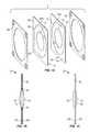
- FIGS. 1A-1Cprovide exploded, cross-sectional and side views, respectively, of a fluidic optical lens system of the present invention having a fixed volume of fluid, which is employable as an adjustable-focus lens;
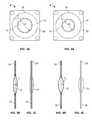
- FIGS. 2A and 2Bprovide schematic illustrations of an electroactive polymer film for use with the optical systems of the present invention before and after application of a voltage
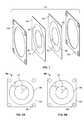
- FIGS. 3A-3Cprovide planar, cross-sectional and side views, respectively, of the fluidic optical lens system of FIGS. 1A-1C when in an inactive (voltage off) state;
- FIGS. 4A-4Cprovide planar, cross-sectional and side views, respectively, of the fluidic optical lens system of FIGS. 1A-1C when in an active (voltage on) state;
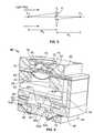
- FIG. 5is a schematic illustration of a lens and the parameters which affect the focal length of the lens
- FIG. 6is a perspective, cross-sectional view of another fluidic optical lens system of the present invention employing a variable volume of fluid;
- FIG. 7is an exploded view of another optical system of the present invention which is employable as a light control aperture
- FIGS. 8A and 8Bprovide planar views of the optical system of FIG. 7 when in inactive (voltage off) and active (voltage on) states, respectively;
- FIG. 9is an exploded view of another optical system of the present invention which is employable as a light control aperture
- FIGS. 10A and 10Bprovide planar views of the optical system of FIG. 9 when in inactive (voltage off) and active (voltage on) states, respectively;
- FIG. 11is an exploded view of another optical system of the present invention which is employable as a shutter
- FIGS. 12A and 12Bprovide planar views of the optical system of FIG. 11 when in inactive (voltage off) and active (voltage on) states, respectively;
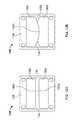
- FIGS. 13A-13Care schematic illustrations of a conventional lens system in neutral, zoom-out and zoom-in positions, respectively.
- FIGS. 14A-14Care schematic illustrations of a liquid lens system of the present invention in the neutral, zoom-out and zoom-in positions, respectively.
- Optical system 2includes electroactive films 10 , each including a dielectric layer 18 , a portion of which is sandwiched between two electrode layers 24 , with the high voltage electrodes of each film 10 facing each other and the grounded electrodes facing outward.
- Each electroactive filmhas an electrical contact portion 22 configured for electrical connection to a voltage source (not shown). While a two-ply film configuration is illustrated, a single-ply film configuration may also be employed; however, the two-ply structure minimizes the risk of arcing from the high voltage electrode.
- a separate non-active filmmay be needed to fully enclose the fluid chamber. Notwithstanding, there may be instances where a single film is advantageous. Further, more than two layers may be employed, for example, where additional force is needed. Configurations having more than two layers of electroactive film may also allow for an asymmetrical lens shape where the stiffness of the films may vary from each other to enable such asymmetry. The structure and function of the electroactive films are discussed in greater detail below with reference to FIGS. 2A and 2B .
- each film 10Disposed centrally within each film 10 is a transparent and/or translucent membrane 14 which, when sealed together about their perimeters 16 as shown in FIGS. 1B and 1C , define a liquid lens 12 . More specifically, the sealed membranes 14 define a chamber which encapsulates an optical fluid.
- the perimeter 16 of lens 12is sealed by means of an adhesive or the membranes 14 themselves may be made of a material that is self-adhesive, e.g., acrylic, silicone, epoxy, cyanoacrylate, etc.
- the sealed perimeter 16may solely include membranes 14 , solely include the electroactive films 10 or include portions of both materials.
- electrodes 24may be spaced a selected distance from membranes 14 to expose respective inner annular portions of the dielectric layers 18 .
- the dielectric layer 18 of each filmmay itself be made of a transparent/translucent material with a central portion defining optical membrane 14 .
- the optical membranemay be transparent without being translucent, or visa versa, or may be both transparent and translucent. Unless specified otherwise, the terms are used interchangeably herein.
- the optical membranes and electroactive filmscollectively define a diaphragm which is stretched and held about its perimeter by a frame or is otherwise sandwiched between two opposing open frame sides 20 . While frame 20 is illustrated having a square configuration, any suitable configuration may be used.
- the composite structure which forms lens system 2may be referred to as a cartridge.
- the cartridgewhich may have any suitable form fit and size, may be incorporated into many types of optical devices, such as those listed above.
- frame 20may have a width, length or diameter dimension in the range from about 5 to about 15 millimeters and have a thickness in the range from about 0.1 to about 1 millimeters; and lens 12 may have a diameter in the range from about 1 to about 25 millimeters and a lens radius (when in an inactive condition) in the range from about 0.1 to infinity (i.e., nearly flat).
- the fluid used within lens 12may be a liquid or gel, and typically has a refractive index between about 1.1 and about 3.0, depending on the application.
- the fluiddesirably has a viscosity of about 0.1 to about 100 centipoises over a temperature range from about ⁇ 10° C. to about 80° C.
- Fluids which have these properties and are suitable for use with the present inventioninclude but are not limited to silicone oil, e.g., Bis-Phenylpropyl Dimethicone.
- the fluidmay include dopants, dyes, pigments, particles, nanoparticle and/or chemical elements that serve to modify the transmissive optical properties of the fluid.
- the fluidmay include infrared absorbing particles or pigments that serve as a filter to prevent infrared wavelengths of about 670 nm and greater from being transmitted through the fluidic lens while allowing visible wavelengths to be transmitted generally without loss.
- the transparent/translucent membranes 14act as optical interfaces disposed between the lens fluid and the external environment within which the lens 12 is disposed, it is preferable if they have a refractive index matched, i.e., equal or nearly equal, to that of the optical fluid in order to minimize scattering of light at their interface.
- the external environmentwill be air at standard atmospheric pressure.
- At least one and often both of the two membranes 14 which define the lens chamberpreferably have properties suitable for use in a variable focal length lens.
- the membrane materialshould be sufficiently elastic, rugged, and transparent to radiation in a frequency range of interest, e.g., visible light. Additionally, the membrane material should be durable enough to have a lifetime suitable for its application. For example, in a cell phone camera application, the membrane material should have a lifetime of several years and be able to survive about one million cycles of operation.
- Suitable membrane materials for use with the present inventioninclude but are not limited to silicone-based polymers, such as poly(dimethylsiloxane) (PDMS), or a polyester material, such as PET or MylarTM.
- electroactive film 26comprises a composite of materials which includes a thin polymeric dielectric layer 28 sandwiched between compliant electrode plates or layers 30 , thereby forming a capacitive structure.
- a voltageis applied across the electrodes, the unlike charges in the two electrodes 30 are attracted to each other and these electrostatic attractive forces compress the dielectric layer 28 (along the Z-axis). Additionally, the repulsive forces between like charges in each electrode tend to stretch the dielectric in plane (along the X- and Y-axes), thereby reducing the thickness of the film.
- the dielectric layer 28is thereby caused to deflect with a change in electric field.
- electrodes 30As electrodes 30 are compliant, they change shape with dielectric layer 28 .
- deflectionrefers to any displacement, expansion, contraction, torsion, linear or area strain, or any other deformation of a portion of dielectric layer 28 .
- this deflectionmay be used to produce mechanical work.
- the electroactive film 26may be pre-strained within the frame to improve conversion between electrical and mechanical energy, i.e., the pre-strain allows the film to deflect more and provide greater mechanical work.
- the electroactive film 26continues to deflect until mechanical forces balance the electrostatic forces driving the deflection.
- the mechanical forcesinclude elastic restoring forces of the dielectric layer 28 , the compliance of the electrodes 30 and any external resistance provided by a device and/or load coupled to film 26 .
- the resultant deflection of the film as a result of the applied voltagemay also depend on a number of other factors such as the dielectric constant of the elastomeric material and its size and stiffness. Removal of the voltage difference and the induced charge causes the reverse effects, with a return to the inactive state as illustrated in FIG. 2A .
- the length L and width W of electroactive polymer film 26are much greater than its thickness t.
- the dielectric layer 28has a thickness in range from about 1 ⁇ m to about 100 ⁇ m and is likely thicker than each of the electrodes. It is desirable to select the elastic modulus and thickness of electrodes 30 such that the additional stiffness they contribute to the actuator is generally less than the stiffness of the dielectric layer, which has a relatively low modulus of elasticity, i.e., less than about 100 MPa.
- Classes of electroactive polymer materials suitable for use with the subject optical systemsinclude but are not limited to dielectric elastomers, electrostrictive polymers, electronic electroactive polymers, and ionic electroactive polymers, and some copolymers.
- Suitable dielectric materialsinclude but are not limited to silicone, acrylic, polyurethane, flourosilicone, etc.
- Electrostrictive polymersare characterized by the non-linear reaction of electroactive polymers. Electronic electroactive polymers typically change shape or dimensions due to migration of electrons in response to electric field (usually dry). Ionic electroactive polymers are polymers that change shape or dimensions due to migration of ions in response to electric field (usually wet and contains electrolyte).
- Suitable electrode materialsinclude carbon, gold, platinum, aluminum, etc.
- Suitable films and materials for use with the diaphragm cartridges of the present inventionare disclosed in the following U.S. Pat. Nos. 6,376,971, 6,583,533, 6,664,718, which are herein incorporated by reference.
- FIGS. 3 and 4illustrate the inactive and active states, respectively, of the lens system 2 of FIGS. 1A-1C , which states correspond respectively to the inactive and active states of the electroactive/dielectric film 10 used in the system, as illustrated in FIGS. 2A and 2B .
- the electroactive film(s)is radially dilated which results in a corresponding dilation (i.e., inactive state as illustrated in FIG. 3A-3C ) and contraction (i.e., active state as illustrated in FIGS. 4A-4C ) of optical membranes 14 and, thus, lens 12 .
- the radius of curvature of a bounding surfaceis positive if its center of curvature lies behind the lens, and negative if its center of curvature lies in front of the lens.
- R 1is positive and R 2 is negative.
- the focal length f of a lensis the distance from the optical center of the lens to the lens' focal point.
- the focal pointis located on the camera's sensor.
- the lens maker's formula for a thin lensi.e., lens' thickness d is small compared to its focal length correlates a lens' focal length f to its radii of curvature as follows:
- nis the refractive index of the lens material.
- a liquid lens of the present inventionallows the focal length (focus) of the lens to be selectable or tunable. This is accomplished by controlling or regulating the amount of voltage applied to the electroactive film 10 . As the applied voltage increases, the radius r of the lens 12 decreases. Since the liquid volume of the lens is constant, the radii of curvature R 1 , R 2 of the lens increase, which in turn increases the lens' focal length f. Conversely, as the voltage is reduced, the lens radius r increases thereby decreasing the radii of curvature and decreasing the lens' focal length f. Control electronics integrated with the platform device, e.g., camera, and interfaced with the lens system can be programmed and used to control the application of voltage to the electroactive film thereby modulating the focal length of the lens.
- the platform devicee.g., camera
- the previously described fluidic lens system of the present inventioninvolves a liquid lens having a fixed volume of fluid.
- the present inventionalso includes fluidic lens systems 40 , illustrated in FIG. 6 , in which the volume of fluid present within the liquid lens can be varied in order to tune the focal length of the lens. More particularly, fluid is selectively transferred in and out of the fluidic lens chamber 42 and to and from a remote driving chamber 44 via a fluid passage 48 . As is explained in greater detail below, this fluid transfer is accomplished by hydraulic means which provides a pumping action generated by an electroactive component employed as an actuator 46 .
- the lens portion of the illustrated lens system 40includes converging or bi-convex lens.
- the “front” sideis defined by a liquid lens 42 having a fluid chamber defined on its front side by a stretchable, transparent membrane 68 extending across an aperture 64 in a bottom or proximal lens housing 66 , and defined on a back side by a rigid, transparent cover or plate 70 .
- Plate 70is held between bottom or proximal housing 66 and top or distal lens housing 72 .
- a solid/rigid optical lens 76On the opposite side of transparent plate 70 is a solid/rigid optical lens 76 having a converging backside which extends into conical aperture 80 .
- lens 76is made of polycarbonate or glass but may be made any other suitable material.
- the cone angle of aperture 80dictates the angle at which light rays impinge upon plate 70 .
- an optical stop 74Positioned between plate 70 and rigid lens 76 is an optical stop 74 which blocks undesirable, i.e., scattered or random, light rays from passing into liquid lens 42 .
- an infrared (IR) filter 78As with conventional lens systems, an infrared (IR) filter 78 , set within a cutout within the face of top housing 72 , is provided on the opposite side of rigid lens 76 .
- an image sensor 82Positioned on the opposite side of membrane 68 is an image sensor 82 which receives the image for digital processing by an image processing chip (not shown).
- Driving portion of the lens systemincludes a fluidic driving chamber 44 defined on one end by a distal or top housing 58 having side walls.
- the proximal or bottom end of chamber 44is receives a piston 54 .
- a flexible diaphragm 56 formed of a non-permeable materialextends annularly about the distal or chamber end 54 a of piston 54 with its outer edge captured within the chamber housing 58 .
- Diaphragm 56acts to fluidly seal chamber 44 while enabling a bellows-type action to pump fluid in and out of the chamber.
- the proximal or driving end 54 b of piston 54is operatively coupled to electroactive actuator 46 which acts to drive a piston 54 in and out of chamber 44 .
- electroactive actuator 46acts to drive a piston 54 in and out of chamber 44 .
- piston 54drives against chamber 44
- the positive pressure placed in the chambercauses the lens fluid to flow out of the chamber through passageway 48 into lens chamber 42 .
- piston 48is withdrawn, a negative pressure is created within chamber 44 , thereby causing the system's fluid to be drawn into chamber 44 and out of lens chamber 42 .
- electroactive actuator 46has a frustum diaphragm configuration in which an electroactive film 52 (as described with respect to FIGS. 2A and 2B ) is held between outer and inner open frame members 50 a, 50 b.
- electroactive film 52as described with respect to FIGS. 2A and 2B
- Such frustum-type actuatorsare described in detail in U.S. patent application Ser. Nos. 11/085,798, 11/085,804 and 11/618,577, each incorporated by reference in its entirety.
- Outer frame member 50 ais held fixed within actuator housing 60 and inner frame member 50 b is in turn coupled to a proximal end 54 a of piston 54 .
- Diaphragm 56places a bias on piston 54 and on inner frame 50 b in the direction of arrow 62 b such that when a voltage is applied to actuator 46 , inner frame member 50 b is moved further in this biased direction, thereby creating a negative pressure in chamber 44 and drawing fluid from passage 48 in to chamber 44 . As the voltage is removed, the reverse motion is experienced by piston 54 and inner frame 50 b, creating a positive pressure in chamber 44 and forcing fluid into the passage 48 toward the lens chamber 42 .
- the amount of voltage applied to actuator 46may be selectively controlled to modulate the extent of pumping action undergone by the system, and thus, finely tuning the volume of fluid present in lens chamber 42 .
- optical system 90functions similarly to the eye's iris in that the diameter of the aperture defined by the iris is adjusted to regulate the amount of light passing therethrough.
- Optical system 90includes a two-ply transparent/translucent membrane 92 which defines the light-passing aperture. Extending radially outward from at least a portion of each membrane 92 is an electroactive film including a dielectric layer 94 , a portion of which is sandwiched between two electrode layers 96 . As with the auto-focus lens system described above, a single film layer may alternatively be employed. The structure and function of the iris' electroactive films is as discussed above with respect to FIGS. 2A and 2B .
- the electrode layers 96are provided annularly about their associated membranes 92 .
- Each electroactive filmhas an electrical contact portion 98 configured for electrical connection to a voltage source (not shown).
- the optical membranes and electroactive film(s)define a diaphragm which is stretched and held about its perimeter by a frame or is otherwise sandwiched between two opposing open frame sides 100 . While frame 100 is illustrated having a square configuration, any suitable configuration may be used.
- This composite structurewhich may also be referred to as a cartridge, as with the subject lens systems, may have any suitable form fit and size, and may be incorporated into many types of optical devices.
- FIGS. 8A and 8Billustrate the inactive and active states, respectively, of optical system 90 , which states correspond respectively to the inactive and active states of the electroactive film used in the system, as illustrated in FIGS. 2A and 2B , respectively.
- the electroactive film(s)is radially dilated which results in a corresponding dilation of iris aperture 92 , which in turn allows more light to pass therethrough.
- the active stateas illustrated in FIG. 8B , the electroactive film(s) is radially contracted, which restricts or reduces the amount of light that can pass therethrough.
- system 90is usable and useful with any lens system in which the amount of light impinging upon the lenses affects the image.
- optical system 90may be employed with either of the fixed-volume ( FIGS. 1 , 3 and 4 ) or variable-volume ( FIG. 6 ) liquid lens systems of the present invention, as well as with conventional lens systems.
- adjustable aperture 90is positioned on the “back” side of the lenses such that the amount of light impinging on the lenses is controlled. If a filter, such as IR filter 78 of the variable-volume lens system of FIG. 6 , is employed, iris 90 may be positioned on either side of the filter.
- FIGS. 9 , 10 A and 10 Billustrate another iris or aperture system 110 of the present invention.
- Aperture 110is similarly constructed to aperture 90 of FIGS. 7 and 8 , having two electroactive films 112 , each having a dielectric layer 116 sandwiched between two electrode layers 114 , with the high voltage electrodes facing towards each other.
- Frame sides 120hold the films together in a cartridge structure while providing an open space or passage defining the working area of the subject apertures.
- a difference between aperture 110 and aperture 90is that each of the dielectric polymer layers 116 has a cut-out 118 to define an opening therethrough.
- the cut-outis preferably circular, leaving behind an annular portion of dielectric material 116 which is opaque rather than transparent.
- a centrally positioned, opaque polymer disc 122is provided on each film layer 112 and a frame side 120 .
- Disc 122has a central opening or aperture 124 which lies within cut-out 118 and through which light passes when operatively employed within an optical system.
- the outer perimeter of disc 122may be sealed to the inner perimeter of dielectric film 116 by means of an adhesive or the two components may be made of materials that are self-adhesive, e.g., acrylic, silicone, etc. With an annular configuration, disc 122 evenly distributes the tension on layer 116 . Additionally, the two components act to pre-strain each other.
- the same type of polymermay be used for dielectric layer 116 and disc 122 ; however, the polymer types need not be the same. In either case, disc 122 is typically thicker and has a higher pre-strain than dielectric layer 116 , making it “stronger” and stiffer than dielectric layer 116 .
- FIGS. 10A and 10Billustrate the inactive and active states, respectively, of optical system 110 , which states correspond respectively to the inactive and active states of the electroactive film used in the system, as illustrated in FIGS. 2A and 2B , respectively.
- the inactive stateas illustrated in FIG. 10A , the electroactive film(s) and dilatable disc(s) 116 are radially dilated which results in a corresponding dilation of disc aperture or opening 124 , which in turn allows more light to pass therethrough.
- the active stateas illustrated in FIG.
- the electroactive film(s) and dilatable disc(s) 116are radially contracted which results in a corresponding contraction of disc aperture or opening 124 , which in turn restricts or reduces the amount of light that can pass through aperture 124 .
- the radius r of opening 124is greater in the inactive state than in the active state (see r 1 in FIG. 10A vs. r 2 in FIG. 10B ). Controlling the extent to which the radial dimension of opening 124 is dilated or contracted correspondingly adjusts the amount of light passing through it.
- system 110is also usable and useful with either of the fixed-volume ( FIGS. 1 , 3 and 4 ) or variable-volume ( FIG. 6 ) liquid lens systems of the present invention, as well as with conventional lens systems.
- FIGS. 11 , 12 A and 12 Billustrate shutter system 130 of the present invention which also utilizes electroactive films.
- Shutter 130includes two electroactive film layers 132 a and 132 b.
- Each electroactive film 132 a, 132 bis comprised of a dielectric transparent/translucent polymer film 134 and an electrode pair 136 with the two electrodes disposed on opposite sides of each polymer film 134 , the high voltage electrodes facing inward toward each other.
- the electrode pair 136 a disposed on electroactive film 132 ais positioned at a bottom or lower portion of the rectangularly-shaped film, while electrode pair 136 b is disposed on a top or upper portion of electroactive film 136 b which also has a rectangular shape.
- Three open frames with matching cut-out portionsare employed to operatively hold films 132 a, 132 b.
- Two outer frames 138 , 139sandwich the films together while a third frame 140 is positioned between the two films.
- the front or centrally disposed edges 142 a, 142 b of the respective active areas, i.e., the electroded areasare spaced a short distance apart when in their inactive states.
- films 132 a, 132 bare not physically coupled together, however they may still be electrically coupled together and powered by the same power source.
- each filmis held and stretched substantially uniformly on only these three sides, i.e., the frames hold these sides substantially close to their perimeters.
- the front edges 142 a, 142 b, respectively, of each of the active areasis held in tension by the frame ends furthest from the edges, i.e., frame ends 138 a, 139 a, 140 a for active area 136 a and frame ends 138 b, 139 b, 140 b for active area 136 b
- the tension or pre-strain placed on the front edgesis less than that placed on the other edges of the active area.
- the primary movement of the respective active regions upon actuationis along their front edges 142 a, 142 b.
- FIGS. 12A and 12Billustrate the inactive and active states, respectively, of shutter system 130 , which states correspond respectively to the inactive and active states of the electroactive film used in the system, as illustrated in FIGS. 2A and 2B , respectively.
- the inactive stateas illustrated in FIG. 12A , the front edges 142 a, 142 b of the respective active areas of electroactive films 132 a, 132 b are spaced a distance apart thereby defining a transparent, open space between the active areas. This spacing is sufficient to expose the lens and/or aperture (in phantom) 135 that would be positioned behind the films.
- edges 142 a, 142 b of the respective active areasare caused to expand linearly toward each other.
- edges 142 a and 142 boverlap each other to the extent necessary to cover the lens and/or aperture (not shown).
- the shutteris open (i.e., the films are inactive) when it is desirous to expose the image sensor to light, typically not more than about 30 ms.
- Shutter system 130is usable and useful with any of the lens and aperture systems of the present invention, as well as with conventional optical systems.
- the one or more shutter filmsmay have any suitable number and shapes of opaque (electroded) and transparent/translucent portions. Because the shutter's function is to be in either one of two discrete states, i.e., open or closed, the variability of the open circular film configurations of the above-described aperture systems, is not necessary. However, a circular configuration (i.e., where the opaque electrode portion defines a circular transparent portion) maybe employed where the closed position of the aperture is such that area of the transparent/translucent portion is substantially negligible. In any case, the surface area of the opaque portion(s) of the electroactive film when expanded or extended upon activation covers the light-passing aperture.
- the present inventionalso provides optical systems with zoom capabilities. While more complex zoom lenses may have upwards of thirty individual lens elements, and multiple parts to move the lens elements, most conventional zoom lens systems follow the same basic design, as illustrated in FIGS. 13A-13C .
- a conventional zoom lens stack 150consists of two parts: a focusing lens 152 similar to a standard, fixed-focal-length photographic lens preceded by an afocal zoom system 154 , which does not focus the light, but alters the size of a beam of light 155 traveling through it, and thus the overall magnification of the lens system.
- Afocal zoom system 154consists of an arrangement of fixed and movable lens elements.
- the afocal system 154consists of two positive (converging) lenses of equal focal length 154 a, 154 c with a negative (diverging) lens 154 b between them and having an absolute focal length less than half that of the positive lenses.
- Lenses 154 a, 154 care fixed, but lens 154 b can be moved axially along the longitudinal axis of the lens stack 150 .
- lens 154 amay also be movable. Movement of the lens(es) is usually performed by a complex arrangement of gears and cams in the lens housing, although some modern zoom lenses use computer-controlled servos to perform this positioning.
- diverging lens 154 bWhen diverging lens 154 b is positioned equidistance between converging lenses 154 a, 154 c (see FIG. 13A ), the system is neutral, i.e., the cross-sectional dimension of the collimated beam of light 155 entering the system remains substantially constant. In other words, there is no magnification of the image on which focusing lens 152 is focused. As diverging lens 154 b moves towards the back B of the stack (see FIG. 13B ), i.e., zooms in, the magnification of the system increases. Conversely, as diverging lens 154 b moves towards the front F of the stack (see FIG. 13C ), i.e., zooms out, the magnification of the system decreases.
- the focal length of a zoom lensis given as a range of two figures, the first is the focal length (mm) when the zoom is not being used and the second is the focal length (mm) when the zoom is fully extended.
- the zoom ratiois the ratio of the focal length with the zoom fully extended to the focal length when the zoom is not being used.
- a typical conventional digital camerahas a focal length of 35 mm without zoom and a focal length of 105 mm with zoom. Thus, the camera's zoom ratio is about 3 ⁇ . In order to increase a camera's zoom ratio, either larger lenses or more of them must be used. This in turn requires more space for the lenses as well as for the cams and gears needed to move the lenses.
- this compensationmay be done by mechanical means, i.e., moving the complete lens assembly as the magnification of the lens changes, or optically, i.e., arranging the position of the focal plane to vary as little as possible as the lens is zoomed.
- the present inventionovercomes these shortcomings of conventional optical zoom systems by utilizing one or more of the subject liquid lenses in a lens stack assembly to provide zoom capabilities with reduced space requirements and with less weight added to the overall system or device.
- Lens system 160includes focusing lens 162 at a back end B of lens stack 160 and an afocal zoom system 164 proximal thereto.
- zoom system 164does not include any moving lens elements, i.e., all of the lenses are fixed as their movement is not required to effect image magnification.
- electroactive film actuators disclosed in the patent references incorporated hereinmay be employed to linearly translate the lens elements to affect a zoom effect.
- afocal zoom system 164consists of two positive (converging) lenses 164 a, 164 c and a negative (diverging) lens 164 b therebetween.
- One or more of the afocal lensesmay be a liquid lens, such as the liquid lens of FIGS. 1A-1C .
- at least two of the afocal lensesare liquid lenses.
- converging lenses 164 a and 164 care liquid lenses and diverging lens 164 b is a conventional solid lens.
- any two (or more) of the afocal lensesmay have a liquid configuration.
- Either a liquid lens of the present invention or a conventional solid lensmay be used for focusing lens 162 , which is converging on its front end.
- afocal lens 164 c and focusing lens 162may be integrated into a single converging lens, which may be liquid or solid; however, image quality may be compromised.
- the thicknesses (t a , t b , t c ) of the respective liquid lensesmay be adjusted.
- the change in lens thicknessmay be effected by varying the diameter/radius of the lens, as with the fixed volume liquid lens system of FIGS. 1A-1C , or by varying the volume of liquid within the lens chamber, as with the variable volume liquid lens system of FIG.
- each of the afocal lensesas a selected thickness t a , t b , t c , respectively.
- the thickness t a of lens 164 ais reduced and the thickness t b of is increased proportionately.
- the thickness t a of lens 164 ais increased and the thickness t c of is decreased proportionately.
- a solid lens having a fixed thicknessmay be readily employed in lieu of a liquid lens. It is to be understood, however, that any combination of liquid and solid lenses, and less or more than three afocal lenses may be employed with the optical zoom systems of the present invention.
- the zoom ratio of the subject optical systemsmay be made to be greater than 3 ⁇ , and even greater than 10 ⁇ or more.
- Methods of the present invention associated with the subject optical systems, devices, components and elementsare contemplated.
- such methodsmay include selectively focusing a lens on an image, selectively adjusting light exposed to a lens or magnifying an image using a lens assembly.
- the methodsmay comprise the act of providing a suitable device or system in which the subject inventions are employed, which provision may be performed by the end user.
- the “providing”e.g., a pump, valve, reflector, etc.
- the subject methodsmay include each of the mechanical activities associated with use of the devices described as well as electrical activity. As such, methodology implicit to the use of the devices described forms part of the invention. Further, electrical hardware and/or software control and power supplies adapted to effect the methods form part of the present invention.
- a kitmay include any number of optical systems according to the present invention.
- a kitmay include various other components for use with the optical systems including mechanical or electrical connectors, power supplies, etc.
- the subject kitsmay also include written instructions for use of the devices or their assembly. Such instructions may be printed on a substrate, such as paper or plastic, etc. As such, the instructions may be present in the kits as a package insert, in the labeling of the container of the kit or components thereof (i.e., associated with the packaging or sub-packaging) etc.
- the instructionsare present as an electronic storage data file present on a suitable computer readable storage medium, e.g., CD-ROM, diskette, etc.
- the actual instructionsare not present in the kit, but means for obtaining the instructions from a remote source, e.g. via the Internet, are provided.
- An example of this embodimentis a kit that includes a web address where the instructions can be viewed and/or from which the instructions can be downloaded. As with the instructions, this means for obtaining the instructions is recorded on suitable media.
- any optional feature of the inventive variations describedmay be set forth and claimed independently, or in combination with any one or more of the features described herein.
- Reference to a singular itemincludes the possibility that there are plural of the same items present. More specifically, as used herein and in the appended claims, the singular forms “a,” “an,” “said,” and “the” include plural referents unless the specifically stated otherwise. In other words, use of the articles allow for “at least one” of the subject item in the description above as well as the claims below. It is further noted that the claims may be drafted to exclude any optional element.
Landscapes
- Physics & Mathematics (AREA)
- General Physics & Mathematics (AREA)
- Optics & Photonics (AREA)
- Nonlinear Science (AREA)
- Mechanical Light Control Or Optical Switches (AREA)
Abstract
Description
Claims (13)
Priority Applications (1)
| Application Number | Priority Date | Filing Date | Title |
|---|---|---|---|
| US12/768,846US8164835B2 (en) | 2007-05-31 | 2010-04-28 | Optical systems employing compliant electroactive materials |
Applications Claiming Priority (3)
| Application Number | Priority Date | Filing Date | Title |
|---|---|---|---|
| US94122207P | 2007-05-31 | 2007-05-31 | |
| US12/128,576US7733575B2 (en) | 2007-05-31 | 2008-05-28 | Optical systems employing compliant electroactive materials |
| US12/768,846US8164835B2 (en) | 2007-05-31 | 2010-04-28 | Optical systems employing compliant electroactive materials |
Related Parent Applications (1)
| Application Number | Title | Priority Date | Filing Date |
|---|---|---|---|
| US12/128,576ContinuationUS7733575B2 (en) | 2007-05-31 | 2008-05-28 | Optical systems employing compliant electroactive materials |
Publications (2)
| Publication Number | Publication Date |
|---|---|
| US20110157675A1 US20110157675A1 (en) | 2011-06-30 |
| US8164835B2true US8164835B2 (en) | 2012-04-24 |
Family
ID=40094077
Family Applications (2)
| Application Number | Title | Priority Date | Filing Date |
|---|---|---|---|
| US12/128,576ActiveUS7733575B2 (en) | 2007-05-31 | 2008-05-28 | Optical systems employing compliant electroactive materials |
| US12/768,846ActiveUS8164835B2 (en) | 2007-05-31 | 2010-04-28 | Optical systems employing compliant electroactive materials |
Family Applications Before (1)
| Application Number | Title | Priority Date | Filing Date |
|---|---|---|---|
| US12/128,576ActiveUS7733575B2 (en) | 2007-05-31 | 2008-05-28 | Optical systems employing compliant electroactive materials |
Country Status (4)
| Country | Link |
|---|---|
| US (2) | US7733575B2 (en) |
| EP (1) | EP2206013A4 (en) |
| KR (1) | KR101210116B1 (en) |
| WO (1) | WO2008150817A1 (en) |
Cited By (9)
| Publication number | Priority date | Publication date | Assignee | Title |
|---|---|---|---|---|
| US9195058B2 (en) | 2011-03-22 | 2015-11-24 | Parker-Hannifin Corporation | Electroactive polymer actuator lenticular system |
| US9231186B2 (en) | 2009-04-11 | 2016-01-05 | Parker-Hannifin Corporation | Electro-switchable polymer film assembly and use thereof |
| US9425383B2 (en) | 2007-06-29 | 2016-08-23 | Parker-Hannifin Corporation | Method of manufacturing electroactive polymer transducers for sensory feedback applications |
| US9553254B2 (en) | 2011-03-01 | 2017-01-24 | Parker-Hannifin Corporation | Automated manufacturing processes for producing deformable polymer devices and films |
| US9590193B2 (en) | 2012-10-24 | 2017-03-07 | Parker-Hannifin Corporation | Polymer diode |
| US9634225B2 (en) | 2012-12-17 | 2017-04-25 | Apple Inc. | Artificial muscle camera lens actuator |
| US9761790B2 (en) | 2012-06-18 | 2017-09-12 | Parker-Hannifin Corporation | Stretch frame for stretching process |
| US9876160B2 (en) | 2012-03-21 | 2018-01-23 | Parker-Hannifin Corporation | Roll-to-roll manufacturing processes for producing self-healing electroactive polymer devices |
| US9915830B2 (en) | 2013-08-06 | 2018-03-13 | E. Thomas CURLEY | Attachable corrective optical lenses |
Families Citing this family (137)
| Publication number | Priority date | Publication date | Assignee | Title |
|---|---|---|---|---|
| US7672059B2 (en)* | 2000-10-20 | 2010-03-02 | Holochip Corporation | Fluidic lens with electrostatic actuation |
| US7218430B2 (en)* | 2000-10-20 | 2007-05-15 | Robert G Batchko | Combinatorial optical processor |
| US7646544B2 (en)* | 2005-05-14 | 2010-01-12 | Batchko Robert G | Fluidic optical devices |
| US8503875B2 (en)* | 2008-11-17 | 2013-08-06 | Holochip Corporation | Fluidic viewfinder device |
| US8064142B2 (en) | 2005-05-14 | 2011-11-22 | Holochip Corporation | Fluidic lens with reduced optical aberration |
| US7948683B2 (en)* | 2006-05-14 | 2011-05-24 | Holochip Corporation | Fluidic lens with manually-adjustable focus |
| US7697214B2 (en) | 2005-05-14 | 2010-04-13 | Holochip Corporation | Fluidic lens with manually-adjustable focus |
| EP2206013A4 (en)* | 2007-05-31 | 2011-07-20 | Artificial Muscle Inc | Optical systems employing compliant electroactive materials |
| WO2009023635A1 (en)* | 2007-08-10 | 2009-02-19 | Board Of Regents, The University Of Texas System | Forward-imaging optical coherence tomography (oct) systems and probe |
| US9274612B2 (en) | 2008-01-04 | 2016-03-01 | Tactus Technology, Inc. | User interface system |
| US8243038B2 (en) | 2009-07-03 | 2012-08-14 | Tactus Technologies | Method for adjusting the user interface of a device |
| US9063627B2 (en) | 2008-01-04 | 2015-06-23 | Tactus Technology, Inc. | User interface and methods |
| US9423875B2 (en) | 2008-01-04 | 2016-08-23 | Tactus Technology, Inc. | Dynamic tactile interface with exhibiting optical dispersion characteristics |
| US9588683B2 (en) | 2008-01-04 | 2017-03-07 | Tactus Technology, Inc. | Dynamic tactile interface |
| US20160187981A1 (en) | 2008-01-04 | 2016-06-30 | Tactus Technology, Inc. | Manual fluid actuator |
| US9298261B2 (en) | 2008-01-04 | 2016-03-29 | Tactus Technology, Inc. | Method for actuating a tactile interface layer |
| US9052790B2 (en) | 2008-01-04 | 2015-06-09 | Tactus Technology, Inc. | User interface and methods |
| US8553005B2 (en) | 2008-01-04 | 2013-10-08 | Tactus Technology, Inc. | User interface system |
| US9720501B2 (en) | 2008-01-04 | 2017-08-01 | Tactus Technology, Inc. | Dynamic tactile interface |
| US9612659B2 (en) | 2008-01-04 | 2017-04-04 | Tactus Technology, Inc. | User interface system |
| US8922510B2 (en) | 2008-01-04 | 2014-12-30 | Tactus Technology, Inc. | User interface system |
| US9552065B2 (en) | 2008-01-04 | 2017-01-24 | Tactus Technology, Inc. | Dynamic tactile interface |
| US8947383B2 (en) | 2008-01-04 | 2015-02-03 | Tactus Technology, Inc. | User interface system and method |
| US9128525B2 (en) | 2008-01-04 | 2015-09-08 | Tactus Technology, Inc. | Dynamic tactile interface |
| US9430074B2 (en) | 2008-01-04 | 2016-08-30 | Tactus Technology, Inc. | Dynamic tactile interface |
| US8547339B2 (en) | 2008-01-04 | 2013-10-01 | Tactus Technology, Inc. | System and methods for raised touch screens |
| US9557915B2 (en) | 2008-01-04 | 2017-01-31 | Tactus Technology, Inc. | Dynamic tactile interface |
| US8456438B2 (en) | 2008-01-04 | 2013-06-04 | Tactus Technology, Inc. | User interface system |
| US8154527B2 (en) | 2008-01-04 | 2012-04-10 | Tactus Technology | User interface system |
| US8704790B2 (en) | 2010-10-20 | 2014-04-22 | Tactus Technology, Inc. | User interface system |
| US8570295B2 (en) | 2008-01-04 | 2013-10-29 | Tactus Technology, Inc. | User interface system |
| CN101978683B (en) | 2008-04-03 | 2013-11-13 | 柯尼卡美能达控股株式会社 | Camera device and method of manufacturing camera device |
| US11792538B2 (en) | 2008-05-20 | 2023-10-17 | Adeia Imaging Llc | Capturing and processing of images including occlusions focused on an image sensor by a lens stack array |
| US8866920B2 (en) | 2008-05-20 | 2014-10-21 | Pelican Imaging Corporation | Capturing and processing of images using monolithic camera array with heterogeneous imagers |
| DK3876510T3 (en) | 2008-05-20 | 2024-11-11 | Adeia Imaging Llc | CAPTURE AND PROCESSING OF IMAGES USING MONOLITHIC CAMERA ARRAY WITH HETEROGENEOUS IMAGES |
| US8629932B2 (en)* | 2008-08-18 | 2014-01-14 | Lensvector, Inc. | Autofocus system and method |
| JP5493609B2 (en)* | 2008-09-18 | 2014-05-14 | ソニー株式会社 | Liquid lens and imaging device |
| US9588684B2 (en) | 2009-01-05 | 2017-03-07 | Tactus Technology, Inc. | Tactile interface for a computing device |
| US7969645B2 (en)* | 2009-02-27 | 2011-06-28 | Sony Ericsson Mobile Communications Ab | Variable lens |
| US8659835B2 (en) | 2009-03-13 | 2014-02-25 | Optotune Ag | Lens systems and method |
| KR20110128929A (en)* | 2009-03-18 | 2011-11-30 | 바이엘 머티리얼사이언스 아게 | Wafer level optical system |
| US9164202B2 (en) | 2010-02-16 | 2015-10-20 | Holochip Corporation | Adaptive optical devices with controllable focal power and aspheric shape |
| WO2011003113A1 (en) | 2009-07-03 | 2011-01-06 | Tactus Technology | User interface enhancement system |
| US8154810B2 (en)* | 2009-07-16 | 2012-04-10 | Microscan Systems, Inc. | Optical assemblies for adjusting working distance and field of view in an imaging system |
| TWI420232B (en)* | 2009-07-27 | 2013-12-21 | Hon Hai Prec Ind Co Ltd | Camera module |
| KR101680300B1 (en)* | 2009-08-31 | 2016-11-28 | 삼성전자주식회사 | Liquid lens and method for manufacturing the same |
| KR101675130B1 (en) | 2009-09-03 | 2016-11-10 | 삼성전자주식회사 | Fluidic lens |
| EP2502115A4 (en) | 2009-11-20 | 2013-11-06 | Pelican Imaging Corp | CAPTURE AND IMAGE PROCESSING USING A MONOLITHIC CAMERAS NETWORK EQUIPPED WITH HETEROGENEOUS IMAGERS |
| WO2011087816A1 (en) | 2009-12-21 | 2011-07-21 | Tactus Technology | User interface system |
| CN102782617B (en) | 2009-12-21 | 2015-10-07 | 泰克图斯科技公司 | User interface system |
| US9298262B2 (en) | 2010-01-05 | 2016-03-29 | Tactus Technology, Inc. | Dynamic tactile interface |
| US8619035B2 (en) | 2010-02-10 | 2013-12-31 | Tactus Technology, Inc. | Method for assisting user input to a device |
| WO2011112984A1 (en) | 2010-03-11 | 2011-09-15 | Tactus Technology | User interface system |
| WO2011133605A1 (en) | 2010-04-19 | 2011-10-27 | Tactus Technology | Method of actuating a tactile interface layer |
| WO2011133604A1 (en) | 2010-04-19 | 2011-10-27 | Tactus Technology | User interface system |
| US8928793B2 (en) | 2010-05-12 | 2015-01-06 | Pelican Imaging Corporation | Imager array interfaces |
| KR101617069B1 (en) | 2010-09-15 | 2016-04-29 | 이-비전 스마트 옵틱스, 아이엔씨. | System, device, and/or methods for managing images |
| KR101912092B1 (en) | 2010-10-05 | 2018-10-26 | 삼성전자 주식회사 | Fluidic lens |
| WO2012048431A1 (en) | 2010-10-14 | 2012-04-19 | Lensvector Inc. | In-flight auto focus method and system for tunable liquid crystal optical element |
| CN103124946B (en) | 2010-10-20 | 2016-06-29 | 泰克图斯科技公司 | User interface system and method |
| KR101912093B1 (en) | 2010-10-29 | 2018-10-26 | 삼성전자 주식회사 | Optical apparatus |
| US8878950B2 (en) | 2010-12-14 | 2014-11-04 | Pelican Imaging Corporation | Systems and methods for synthesizing high resolution images using super-resolution processes |
| EP2708019B1 (en) | 2011-05-11 | 2019-10-16 | FotoNation Limited | Systems and methods for transmitting and receiving array camera image data |
| US20130265459A1 (en) | 2011-06-28 | 2013-10-10 | Pelican Imaging Corporation | Optical arrangements for use with an array camera |
| DE102011053630B4 (en)* | 2011-09-15 | 2019-11-21 | Carl Zeiss Microscopy Gmbh | Method and device for image stabilization in an optical observation or measuring device |
| US20130070060A1 (en) | 2011-09-19 | 2013-03-21 | Pelican Imaging Corporation | Systems and methods for determining depth from multiple views of a scene that include aliasing using hypothesized fusion |
| CN104081414B (en) | 2011-09-28 | 2017-08-01 | Fotonation开曼有限公司 | Systems and methods for encoding and decoding light field image files |
| WO2013055960A1 (en)* | 2011-10-11 | 2013-04-18 | Pelican Imaging Corporation | Lens stack arrays including adaptive optical elements |
| EP2817955B1 (en) | 2012-02-21 | 2018-04-11 | FotoNation Cayman Limited | Systems and methods for the manipulation of captured light field image data |
| WO2013144956A1 (en)* | 2012-03-27 | 2013-10-03 | K.A. Advertising Solutions Ltd. | Reflective dynamic color device |
| US9210392B2 (en) | 2012-05-01 | 2015-12-08 | Pelican Imaging Coporation | Camera modules patterned with pi filter groups |
| JP2015534734A (en) | 2012-06-28 | 2015-12-03 | ペリカン イメージング コーポレイション | System and method for detecting defective camera arrays, optical arrays, and sensors |
| US20140002674A1 (en) | 2012-06-30 | 2014-01-02 | Pelican Imaging Corporation | Systems and Methods for Manufacturing Camera Modules Using Active Alignment of Lens Stack Arrays and Sensors |
| US8921759B2 (en) | 2012-07-26 | 2014-12-30 | Optiz, Inc. | Integrated image sensor package with liquid crystal lens |
| PL4296963T3 (en) | 2012-08-21 | 2025-04-28 | Adeia Imaging Llc | Method for depth detection in images captured using array cameras |
| WO2014032020A2 (en) | 2012-08-23 | 2014-02-27 | Pelican Imaging Corporation | Feature based high resolution motion estimation from low resolution images captured using an array source |
| US9214013B2 (en) | 2012-09-14 | 2015-12-15 | Pelican Imaging Corporation | Systems and methods for correcting user identified artifacts in light field images |
| US9405417B2 (en) | 2012-09-24 | 2016-08-02 | Tactus Technology, Inc. | Dynamic tactile interface and methods |
| EP4307659A1 (en) | 2012-09-28 | 2024-01-17 | Adeia Imaging LLC | Generating images from light fields utilizing virtual viewpoints |
| WO2014078443A1 (en) | 2012-11-13 | 2014-05-22 | Pelican Imaging Corporation | Systems and methods for array camera focal plane control |
| EP2929574A2 (en)* | 2012-12-07 | 2015-10-14 | Bayer Materialscience AG | Electroactive polymer actuated aperture |
| KR20140089129A (en)* | 2013-01-04 | 2014-07-14 | 삼성전자주식회사 | Optical zoom probe |
| US9462164B2 (en) | 2013-02-21 | 2016-10-04 | Pelican Imaging Corporation | Systems and methods for generating compressed light field representation data using captured light fields, array geometry, and parallax information |
| US9374512B2 (en) | 2013-02-24 | 2016-06-21 | Pelican Imaging Corporation | Thin form factor computational array cameras and modular array cameras |
| KR102100926B1 (en) | 2013-02-26 | 2020-04-14 | 삼성전자주식회사 | Variable Liquid Device having nonuniform channel and Apparatus included the same |
| US9774789B2 (en) | 2013-03-08 | 2017-09-26 | Fotonation Cayman Limited | Systems and methods for high dynamic range imaging using array cameras |
| US8866912B2 (en) | 2013-03-10 | 2014-10-21 | Pelican Imaging Corporation | System and methods for calibration of an array camera using a single captured image |
| US9219091B2 (en) | 2013-03-12 | 2015-12-22 | Optiz, Inc. | Low profile sensor module and method of making same |
| US9124831B2 (en) | 2013-03-13 | 2015-09-01 | Pelican Imaging Corporation | System and methods for calibration of an array camera |
| US9888194B2 (en) | 2013-03-13 | 2018-02-06 | Fotonation Cayman Limited | Array camera architecture implementing quantum film image sensors |
| WO2014165244A1 (en) | 2013-03-13 | 2014-10-09 | Pelican Imaging Corporation | Systems and methods for synthesizing images from image data captured by an array camera using restricted depth of field depth maps in which depth estimation precision varies |
| US9106784B2 (en) | 2013-03-13 | 2015-08-11 | Pelican Imaging Corporation | Systems and methods for controlling aliasing in images captured by an array camera for use in super-resolution processing |
| US9578259B2 (en) | 2013-03-14 | 2017-02-21 | Fotonation Cayman Limited | Systems and methods for reducing motion blur in images or video in ultra low light with array cameras |
| WO2014153098A1 (en) | 2013-03-14 | 2014-09-25 | Pelican Imaging Corporation | Photmetric normalization in array cameras |
| WO2014150856A1 (en) | 2013-03-15 | 2014-09-25 | Pelican Imaging Corporation | Array camera implementing quantum dot color filters |
| US9445003B1 (en) | 2013-03-15 | 2016-09-13 | Pelican Imaging Corporation | Systems and methods for synthesizing high resolution images using image deconvolution based on motion and depth information |
| US10122993B2 (en) | 2013-03-15 | 2018-11-06 | Fotonation Limited | Autofocus system for a conventional camera that uses depth information from an array camera |
| US9497429B2 (en) | 2013-03-15 | 2016-11-15 | Pelican Imaging Corporation | Extended color processing on pelican array cameras |
| US9438888B2 (en) | 2013-03-15 | 2016-09-06 | Pelican Imaging Corporation | Systems and methods for stereo imaging with camera arrays |
| US9557813B2 (en) | 2013-06-28 | 2017-01-31 | Tactus Technology, Inc. | Method for reducing perceived optical distortion |
| US9898856B2 (en) | 2013-09-27 | 2018-02-20 | Fotonation Cayman Limited | Systems and methods for depth-assisted perspective distortion correction |
| US9264592B2 (en) | 2013-11-07 | 2016-02-16 | Pelican Imaging Corporation | Array camera modules incorporating independently aligned lens stacks |
| US10119808B2 (en) | 2013-11-18 | 2018-11-06 | Fotonation Limited | Systems and methods for estimating depth from projected texture using camera arrays |
| WO2015081279A1 (en) | 2013-11-26 | 2015-06-04 | Pelican Imaging Corporation | Array camera configurations incorporating multiple constituent array cameras |
| US10089740B2 (en) | 2014-03-07 | 2018-10-02 | Fotonation Limited | System and methods for depth regularization and semiautomatic interactive matting using RGB-D images |
| US9224022B2 (en)* | 2014-04-29 | 2015-12-29 | Hand Held Products, Inc. | Autofocus lens system for indicia readers |
| US9521319B2 (en) | 2014-06-18 | 2016-12-13 | Pelican Imaging Corporation | Array cameras and array camera modules including spectral filters disposed outside of a constituent image sensor |
| US9811095B2 (en)* | 2014-08-06 | 2017-11-07 | Lenovo (Singapore) Pte. Ltd. | Glasses with fluid-fillable membrane for adjusting focal length of one or more lenses of the glasses |
| JP2017531976A (en) | 2014-09-29 | 2017-10-26 | フォトネイション ケイマン リミテッド | System and method for dynamically calibrating an array camera |
| US9910493B2 (en)* | 2014-11-07 | 2018-03-06 | Faurecia Interior Systems, Inc. | Suspension component for a haptic touch panel assembly |
| KR102066234B1 (en)* | 2015-01-27 | 2020-01-14 | 한국전자통신연구원 | Thin active optical zoom lens and apparatus using the same |
| US9543347B2 (en) | 2015-02-24 | 2017-01-10 | Optiz, Inc. | Stress released image sensor package structure and method |
| US9942474B2 (en) | 2015-04-17 | 2018-04-10 | Fotonation Cayman Limited | Systems and methods for performing high speed video capture and depth estimation using array cameras |
| US10310481B2 (en) | 2015-10-07 | 2019-06-04 | International Business Machines Corporation | Dynamic position control for electronic components |
| US10120182B2 (en)* | 2016-10-03 | 2018-11-06 | Semiconductor Components Industries, Llc | Imaging systems with fluidic color filter elements |
| WO2019002565A1 (en)* | 2017-06-30 | 2019-01-03 | Polight As | A transparent optical device element comprising means for selectively transmitting electromagnetic radiation |
| US10482618B2 (en) | 2017-08-21 | 2019-11-19 | Fotonation Limited | Systems and methods for hybrid depth regularization |
| US20200301116A1 (en)* | 2017-12-04 | 2020-09-24 | Optotune Consumer Ag | Optical zoom device with focus tunable lens cores |
| KR102607337B1 (en)* | 2018-05-23 | 2023-11-29 | 엘지이노텍 주식회사 | Liquid lens, camera and optical device including the same |
| KR102089660B1 (en)* | 2019-03-25 | 2020-03-16 | 삼성전자주식회사 | Optical transmittance adjusting device, Image apparatus and Method for manufacturing the device |
| US11270110B2 (en) | 2019-09-17 | 2022-03-08 | Boston Polarimetrics, Inc. | Systems and methods for surface modeling using polarization cues |
| WO2021071992A1 (en) | 2019-10-07 | 2021-04-15 | Boston Polarimetrics, Inc. | Systems and methods for augmentation of sensor systems and imaging systems with polarization |
| DE112020005932T5 (en) | 2019-11-30 | 2023-01-05 | Boston Polarimetrics, Inc. | SYSTEMS AND METHODS FOR SEGMENTATION OF TRANSPARENT OBJECTS USING POLARIZATION CHARACTERISTICS |
| EP4081933A4 (en) | 2020-01-29 | 2024-03-20 | Intrinsic Innovation LLC | Systems and methods for characterizing object pose detection and measurement systems |
| US11797863B2 (en) | 2020-01-30 | 2023-10-24 | Intrinsic Innovation Llc | Systems and methods for synthesizing data for training statistical models on different imaging modalities including polarized images |
| US11953700B2 (en) | 2020-05-27 | 2024-04-09 | Intrinsic Innovation Llc | Multi-aperture polarization optical systems using beam splitters |
| CN112925052B (en)* | 2021-01-29 | 2022-11-08 | 青岛大学 | Focal length adjustable lens based on dielectric elastomer driver and preparation method thereof |
| US12069227B2 (en) | 2021-03-10 | 2024-08-20 | Intrinsic Innovation Llc | Multi-modal and multi-spectral stereo camera arrays |
| US12020455B2 (en) | 2021-03-10 | 2024-06-25 | Intrinsic Innovation Llc | Systems and methods for high dynamic range image reconstruction |
| US11954886B2 (en) | 2021-04-15 | 2024-04-09 | Intrinsic Innovation Llc | Systems and methods for six-degree of freedom pose estimation of deformable objects |
| US11290658B1 (en) | 2021-04-15 | 2022-03-29 | Boston Polarimetrics, Inc. | Systems and methods for camera exposure control |
| US12067746B2 (en) | 2021-05-07 | 2024-08-20 | Intrinsic Innovation Llc | Systems and methods for using computer vision to pick up small objects |
| US12175741B2 (en) | 2021-06-22 | 2024-12-24 | Intrinsic Innovation Llc | Systems and methods for a vision guided end effector |
| US12340538B2 (en) | 2021-06-25 | 2025-06-24 | Intrinsic Innovation Llc | Systems and methods for generating and using visual datasets for training computer vision models |
| US12172310B2 (en) | 2021-06-29 | 2024-12-24 | Intrinsic Innovation Llc | Systems and methods for picking objects using 3-D geometry and segmentation |
| US11689813B2 (en) | 2021-07-01 | 2023-06-27 | Intrinsic Innovation Llc | Systems and methods for high dynamic range imaging using crossed polarizers |
| US12293535B2 (en) | 2021-08-03 | 2025-05-06 | Intrinsic Innovation Llc | Systems and methods for training pose estimators in computer vision |
Citations (36)
| Publication number | Priority date | Publication date | Assignee | Title |
|---|---|---|---|---|
| US4784479A (en)* | 1984-05-30 | 1988-11-15 | Canon Kabushiki Kaisha | Varifocal optical system |
| US5684637A (en) | 1995-07-19 | 1997-11-04 | Floyd; Johnnie E. | Fluid filled and pressurized lens with flexible optical boundary having variable focal length |
| JPH11133210A (en) | 1997-10-30 | 1999-05-21 | Denso Corp | Variable focus lens |
| JP2000081504A (en) | 1998-09-04 | 2000-03-21 | Denso Corp | Variable-focal lens |
| US6232702B1 (en) | 1998-08-18 | 2001-05-15 | The Penn State Research Foundation | Flextensional metal-ceramic composite transducer |
| US6286961B1 (en) | 1997-11-18 | 2001-09-11 | Seiko Epson Corporation | Illuminating optical system and projection type display |
| US6330463B1 (en) | 1997-12-22 | 2001-12-11 | Nokia Mobile Phones Limited | Voltage supply apparatus, in particular for a radio telephone in a motor vehicle |
| US6343129B1 (en) | 1997-02-07 | 2002-01-29 | Sri International | Elastomeric dielectric polymer film sonic actuator |
| US6586859B2 (en) | 2000-04-05 | 2003-07-01 | Sri International | Electroactive polymer animated devices |
| US6619799B1 (en) | 1999-07-02 | 2003-09-16 | E-Vision, Llc | Optical lens system with electro-active lens having alterably different focal lengths |
| US6690101B2 (en) | 2000-03-23 | 2004-02-10 | Elliptec Resonant Actuator Ag | Vibratory motors and methods of making and using same |
| US6812624B1 (en) | 1999-07-20 | 2004-11-02 | Sri International | Electroactive polymers |
| US20040251692A1 (en) | 2002-01-10 | 2004-12-16 | Mats Leijon | Electric device and method |
| US6847155B2 (en)* | 2001-04-24 | 2005-01-25 | Clemson University | Electroactive apparatus and methods |
| US20050078169A1 (en) | 2003-10-08 | 2005-04-14 | Tumer Arthur Monroe | Apparatus and methods for adjusting the rotational frequency of a scanning device |
| US20050140922A1 (en) | 2002-09-04 | 2005-06-30 | Josef Bekerman | Apparatus and method for eyesight rehabilitation |
| US6940211B2 (en) | 1997-02-07 | 2005-09-06 | Sri International | Electroactive polymers transducers and actuators |
| US20060119225A1 (en) | 2001-03-02 | 2006-06-08 | Sri International, A California Corporation | Electroactive polymer motors |
| US20060151449A1 (en) | 2004-12-30 | 2006-07-13 | Warner Raymond M Jr | Parallel-beam scanning for surface patterning of materials |
| US20060208609A1 (en) | 2005-03-21 | 2006-09-21 | Jon Heim | Electroactive polymer actuated devices |
| US20060238066A1 (en) | 1999-07-20 | 2006-10-26 | Sri International | Electroactive polymer generators |
| KR100650190B1 (en) | 2005-07-19 | 2006-11-27 | 삼성전기주식회사 | Light control device using electroactive polymer |
| US7140180B2 (en) | 2003-01-22 | 2006-11-28 | Ocean Power Technologies, Inc. | Wave energy converter (WEC) device and system |
| US7141888B2 (en) | 2004-03-16 | 2006-11-28 | Ocean Power Technologies, Inc. | Antirotational structures for wave energy converters |
| US20070030573A1 (en) | 2005-05-14 | 2007-02-08 | Holochip Corporation | Fluidic optical devices |
| US20070040384A1 (en) | 2003-04-14 | 2007-02-22 | Hans Bernhoff | Wave power assembly with an electromagnetic dampning means |
| US20070070491A1 (en) | 2005-09-23 | 2007-03-29 | Jacob Steve A | Variable focal length electro-optic lens |
| US7237524B2 (en) | 2004-05-26 | 2007-07-03 | Sri International | Compliant walled combustion devices |
| US7242106B2 (en) | 2003-07-18 | 2007-07-10 | Hugh-Peter Granville Kelly | Method of operation for a self-protecting wave energy conversion plant |
| US7256943B1 (en)* | 2006-08-24 | 2007-08-14 | Teledyne Licensing, Llc | Variable focus liquid-filled lens using polyphenyl ethers |
| US20070200457A1 (en) | 2006-02-24 | 2007-08-30 | Heim Jonathan R | High-speed acrylic electroactive polymer transducers |
| US20070216803A1 (en) | 2006-03-15 | 2007-09-20 | Nokia Corporation | Aperture construction for a mobile camera |
| US20070230222A1 (en) | 2006-03-31 | 2007-10-04 | Drabing Richard B | Power circuitry for high-frequency applications |
| US20080062589A1 (en) | 2006-09-08 | 2008-03-13 | Artificial Muscle, Inc. | High-voltage power supplies |
| US20080144185A1 (en)* | 2006-12-15 | 2008-06-19 | Hand Held Products, Inc. | Apparatus and method comprising deformable lens element |
| US7733575B2 (en)* | 2007-05-31 | 2010-06-08 | Artificial Muscle, Inc. | Optical systems employing compliant electroactive materials |
Family Cites Families (11)
| Publication number | Priority date | Publication date | Assignee | Title |
|---|---|---|---|---|
| FR2769375B1 (en)* | 1997-10-08 | 2001-01-19 | Univ Joseph Fourier | VARIABLE FOCAL LENS |
| US20050002113A1 (en)* | 1997-10-08 | 2005-01-06 | Varioptic | Drop centering device |
| US7170665B2 (en)* | 2002-07-24 | 2007-01-30 | Olympus Corporation | Optical unit provided with an actuator |
| US6733130B2 (en)* | 1999-07-02 | 2004-05-11 | E-Vision, Llc | Method for refracting and dispensing electro-active spectacles |
| ATE499624T1 (en)* | 2003-03-17 | 2011-03-15 | Nokia Corp | METHOD AND DEVICE FOR IMAGE ZOOMING |
| KR100616616B1 (en)* | 2004-09-01 | 2006-08-28 | 삼성전기주식회사 | Camera Auto Focusing System |
| FR2878338B1 (en)* | 2004-11-24 | 2007-03-02 | Varioptic Sa | VARIABLE FOCAL LENS MOUNT |
| FR2880135B1 (en)* | 2004-12-23 | 2007-03-16 | Varioptic Sa | VARIABLE FOCAL LENS WITH WIDE RANGE OF VARIATION |
| US7142369B2 (en)* | 2005-01-21 | 2006-11-28 | Research Foundation Of The University Of Central Florida, Inc. | Variable focus liquid lens |
| JP2006285031A (en)* | 2005-04-01 | 2006-10-19 | Sony Corp | Variable focus lens, optical apparatus using the same, manufacturing method of variable focus lens |
| FR2887638B1 (en)* | 2005-06-23 | 2007-08-31 | Varioptic Sa | VARIABLE FOCAL LENS WITH REDUCED INTERNAL PRESSURE VARIATION |
- 2008
- 2008-05-28EPEP08769764Apatent/EP2206013A4/ennot_activeWithdrawn
- 2008-05-28KRKR1020097027486Apatent/KR101210116B1/ennot_activeExpired - Fee Related
- 2008-05-28WOPCT/US2008/065010patent/WO2008150817A1/enactiveApplication Filing
- 2008-05-28USUS12/128,576patent/US7733575B2/enactiveActive
- 2010
- 2010-04-28USUS12/768,846patent/US8164835B2/enactiveActive
Patent Citations (40)
| Publication number | Priority date | Publication date | Assignee | Title |
|---|---|---|---|---|
| US4784479A (en)* | 1984-05-30 | 1988-11-15 | Canon Kabushiki Kaisha | Varifocal optical system |
| US5684637A (en) | 1995-07-19 | 1997-11-04 | Floyd; Johnnie E. | Fluid filled and pressurized lens with flexible optical boundary having variable focal length |
| US6343129B1 (en) | 1997-02-07 | 2002-01-29 | Sri International | Elastomeric dielectric polymer film sonic actuator |
| US6940211B2 (en) | 1997-02-07 | 2005-09-06 | Sri International | Electroactive polymers transducers and actuators |
| JPH11133210A (en) | 1997-10-30 | 1999-05-21 | Denso Corp | Variable focus lens |
| US6286961B1 (en) | 1997-11-18 | 2001-09-11 | Seiko Epson Corporation | Illuminating optical system and projection type display |
| US6330463B1 (en) | 1997-12-22 | 2001-12-11 | Nokia Mobile Phones Limited | Voltage supply apparatus, in particular for a radio telephone in a motor vehicle |
| US6232702B1 (en) | 1998-08-18 | 2001-05-15 | The Penn State Research Foundation | Flextensional metal-ceramic composite transducer |
| JP2000081504A (en) | 1998-09-04 | 2000-03-21 | Denso Corp | Variable-focal lens |
| US6619799B1 (en) | 1999-07-02 | 2003-09-16 | E-Vision, Llc | Optical lens system with electro-active lens having alterably different focal lengths |
| US6812624B1 (en) | 1999-07-20 | 2004-11-02 | Sri International | Electroactive polymers |
| US20060113878A1 (en) | 1999-07-20 | 2006-06-01 | Sri International | Electroactive polymers |
| US20060238066A1 (en) | 1999-07-20 | 2006-10-26 | Sri International | Electroactive polymer generators |
| US20060238079A1 (en) | 1999-07-20 | 2006-10-26 | Sri International, A California Corporation | Electroactive polymers |
| US7259503B2 (en) | 1999-07-20 | 2007-08-21 | Sri International | Electroactive polymers |
| US6690101B2 (en) | 2000-03-23 | 2004-02-10 | Elliptec Resonant Actuator Ag | Vibratory motors and methods of making and using same |
| US6586859B2 (en) | 2000-04-05 | 2003-07-01 | Sri International | Electroactive polymer animated devices |
| US20060119225A1 (en) | 2001-03-02 | 2006-06-08 | Sri International, A California Corporation | Electroactive polymer motors |
| US6847155B2 (en)* | 2001-04-24 | 2005-01-25 | Clemson University | Electroactive apparatus and methods |
| US20040251692A1 (en) | 2002-01-10 | 2004-12-16 | Mats Leijon | Electric device and method |
| US7164212B2 (en) | 2002-01-10 | 2007-01-16 | Swedish Seabased Energy Ab | Electric device and method |
| US20050140922A1 (en) | 2002-09-04 | 2005-06-30 | Josef Bekerman | Apparatus and method for eyesight rehabilitation |
| US7140180B2 (en) | 2003-01-22 | 2006-11-28 | Ocean Power Technologies, Inc. | Wave energy converter (WEC) device and system |
| US20070040384A1 (en) | 2003-04-14 | 2007-02-22 | Hans Bernhoff | Wave power assembly with an electromagnetic dampning means |
| US7242106B2 (en) | 2003-07-18 | 2007-07-10 | Hugh-Peter Granville Kelly | Method of operation for a self-protecting wave energy conversion plant |
| US20050078169A1 (en) | 2003-10-08 | 2005-04-14 | Tumer Arthur Monroe | Apparatus and methods for adjusting the rotational frequency of a scanning device |
| US7141888B2 (en) | 2004-03-16 | 2006-11-28 | Ocean Power Technologies, Inc. | Antirotational structures for wave energy converters |
| US7237524B2 (en) | 2004-05-26 | 2007-07-03 | Sri International | Compliant walled combustion devices |
| US20060151449A1 (en) | 2004-12-30 | 2006-07-13 | Warner Raymond M Jr | Parallel-beam scanning for surface patterning of materials |
| US20060208609A1 (en) | 2005-03-21 | 2006-09-21 | Jon Heim | Electroactive polymer actuated devices |
| US20070030573A1 (en) | 2005-05-14 | 2007-02-08 | Holochip Corporation | Fluidic optical devices |
| KR100650190B1 (en) | 2005-07-19 | 2006-11-27 | 삼성전기주식회사 | Light control device using electroactive polymer |
| US20070070491A1 (en) | 2005-09-23 | 2007-03-29 | Jacob Steve A | Variable focal length electro-optic lens |
| US20070200457A1 (en) | 2006-02-24 | 2007-08-30 | Heim Jonathan R | High-speed acrylic electroactive polymer transducers |
| US20070216803A1 (en) | 2006-03-15 | 2007-09-20 | Nokia Corporation | Aperture construction for a mobile camera |
| US20070230222A1 (en) | 2006-03-31 | 2007-10-04 | Drabing Richard B | Power circuitry for high-frequency applications |
| US7256943B1 (en)* | 2006-08-24 | 2007-08-14 | Teledyne Licensing, Llc | Variable focus liquid-filled lens using polyphenyl ethers |
| US20080062589A1 (en) | 2006-09-08 | 2008-03-13 | Artificial Muscle, Inc. | High-voltage power supplies |
| US20080144185A1 (en)* | 2006-12-15 | 2008-06-19 | Hand Held Products, Inc. | Apparatus and method comprising deformable lens element |
| US7733575B2 (en)* | 2007-05-31 | 2010-06-08 | Artificial Muscle, Inc. | Optical systems employing compliant electroactive materials |
Cited By (9)
| Publication number | Priority date | Publication date | Assignee | Title |
|---|---|---|---|---|
| US9425383B2 (en) | 2007-06-29 | 2016-08-23 | Parker-Hannifin Corporation | Method of manufacturing electroactive polymer transducers for sensory feedback applications |
| US9231186B2 (en) | 2009-04-11 | 2016-01-05 | Parker-Hannifin Corporation | Electro-switchable polymer film assembly and use thereof |
| US9553254B2 (en) | 2011-03-01 | 2017-01-24 | Parker-Hannifin Corporation | Automated manufacturing processes for producing deformable polymer devices and films |
| US9195058B2 (en) | 2011-03-22 | 2015-11-24 | Parker-Hannifin Corporation | Electroactive polymer actuator lenticular system |
| US9876160B2 (en) | 2012-03-21 | 2018-01-23 | Parker-Hannifin Corporation | Roll-to-roll manufacturing processes for producing self-healing electroactive polymer devices |
| US9761790B2 (en) | 2012-06-18 | 2017-09-12 | Parker-Hannifin Corporation | Stretch frame for stretching process |
| US9590193B2 (en) | 2012-10-24 | 2017-03-07 | Parker-Hannifin Corporation | Polymer diode |
| US9634225B2 (en) | 2012-12-17 | 2017-04-25 | Apple Inc. | Artificial muscle camera lens actuator |
| US9915830B2 (en) | 2013-08-06 | 2018-03-13 | E. Thomas CURLEY | Attachable corrective optical lenses |
Also Published As
| Publication number | Publication date |
|---|---|
| US20110157675A1 (en) | 2011-06-30 |
| EP2206013A1 (en) | 2010-07-14 |
| EP2206013A4 (en) | 2011-07-20 |
| US7733575B2 (en) | 2010-06-08 |
| WO2008150817A1 (en) | 2008-12-11 |
| KR101210116B1 (en) | 2012-12-07 |
| US20090021823A1 (en) | 2009-01-22 |
| KR20100031114A (en) | 2010-03-19 |
Similar Documents
| Publication | Publication Date | Title |
|---|---|---|
| US8164835B2 (en) | Optical systems employing compliant electroactive materials | |
| US8605361B2 (en) | Fluidic lens with reduced optical aberration | |
| US10401537B2 (en) | Adaptive optical devices with controllable focal power and aspheric shape | |
| JP4576058B2 (en) | Deformable mirror with displacement detection function | |
| CN102411204B (en) | Liquid lens system | |
| US7701643B2 (en) | Fluidic optical devices | |
| CN102422185B (en) | Lens assembly apparatus and method | |
| US7561185B2 (en) | Shake compensation device for optical devices using a mirror to compensate for the shake | |
| US20080259463A1 (en) | Variable Focal Length Lens | |
| KR20110015569A (en) | Variable Optical Systems and Components | |
| US20080252960A1 (en) | Optical Element | |
| JP2003029150A (en) | Optical system and optical device including optical characteristic variable optical element | |
| CN102439489A (en) | Lens system | |
| KR102318638B1 (en) | Optical devices, especially cameras, with autofocus and image stabilization | |
| US8587874B2 (en) | Fluid Pressure Liquid Lens | |
| CN112823305A (en) | Adjustable optical device | |
| JP2002303783A (en) | Focus adjusting unit of image pickup device | |
| JP2005084654A (en) | Lens housing | |
| JP2006106329A (en) | Optical device |
Legal Events
| Date | Code | Title | Description |
|---|---|---|---|
| AS | Assignment | Owner name:ARTIFICIAL MUSCLE, INC., CALIFORNIA Free format text:ASSIGNMENT OF ASSIGNORS INTEREST;ASSIGNORS:HEIM, JONATHAN R.;ZARRABI, ALIREZA;SIGNING DATES FROM 20040301 TO 20110413;REEL/FRAME:026313/0684 | |
| AS | Assignment | Owner name:BAYER MATERIALSCIENCE AG, GERMANY Free format text:ASSIGNMENT OF ASSIGNORS INTEREST;ASSIGNOR:ARTIFICIAL MUSCLE, INC.;REEL/FRAME:026748/0533 Effective date:20110808 | |
| STCF | Information on status: patent grant | Free format text:PATENTED CASE | |
| FPAY | Fee payment | Year of fee payment:4 | |
| AS | Assignment | Owner name:PARKER-HANNIFIN CORPORATION, OHIO Free format text:ASSIGNMENT OF ASSIGNORS INTEREST;ASSIGNOR:BAYER INTELLECTUAL PROPERTY GMBH;REEL/FRAME:037164/0786 Effective date:20140528 Owner name:BAYER INTELLECTUAL PROPERTY GMBH, GERMANY Free format text:ASSIGNMENT OF ASSIGNORS INTEREST;ASSIGNOR:BAYER MATERIALSCIENCE AG;REEL/FRAME:037164/0220 Effective date:20120326 | |
| AS | Assignment | Owner name:PARKER INTANGIBLES, LLC, OHIO Free format text:ASSIGNMENT OF ASSIGNORS INTEREST;ASSIGNOR:PARKER-HANNIFIN CORPORATION;REEL/FRAME:045843/0859 Effective date:20180405 | |
| MAFP | Maintenance fee payment | Free format text:PAYMENT OF MAINTENANCE FEE, 8TH YEAR, LARGE ENTITY (ORIGINAL EVENT CODE: M1552); ENTITY STATUS OF PATENT OWNER: LARGE ENTITY Year of fee payment:8 | |
| MAFP | Maintenance fee payment | Free format text:PAYMENT OF MAINTENANCE FEE, 12TH YEAR, LARGE ENTITY (ORIGINAL EVENT CODE: M1553); ENTITY STATUS OF PATENT OWNER: LARGE ENTITY Year of fee payment:12 |