US8164222B2 - Laptop and portable electronic device wireless power supply systems - Google Patents
Laptop and portable electronic device wireless power supply systemsDownload PDFInfo
- Publication number
- US8164222B2 US8164222B2US12/252,778US25277808AUS8164222B2US 8164222 B2US8164222 B2US 8164222B2US 25277808 AUS25277808 AUS 25277808AUS 8164222 B2US8164222 B2US 8164222B2
- Authority
- US
- United States
- Prior art keywords
- power supply
- remote device
- cradle
- primary
- power
- Prior art date
- Legal status (The legal status is an assumption and is not a legal conclusion. Google has not performed a legal analysis and makes no representation as to the accuracy of the status listed.)
- Expired - Fee Related, expires
Links
Images


Classifications
- G—PHYSICS
- G06—COMPUTING OR CALCULATING; COUNTING
- G06F—ELECTRIC DIGITAL DATA PROCESSING
- G06F1/00—Details not covered by groups G06F3/00 - G06F13/00 and G06F21/00
- G06F1/26—Power supply means, e.g. regulation thereof
- G—PHYSICS
- G06—COMPUTING OR CALCULATING; COUNTING
- G06F—ELECTRIC DIGITAL DATA PROCESSING
- G06F1/00—Details not covered by groups G06F3/00 - G06F13/00 and G06F21/00
- G06F1/16—Constructional details or arrangements
- G06F1/1613—Constructional details or arrangements for portable computers
- G06F1/1628—Enclosures for carrying portable computers with peripheral devices, e.g. cases for a laptop and a printer
- G—PHYSICS
- G06—COMPUTING OR CALCULATING; COUNTING
- G06F—ELECTRIC DIGITAL DATA PROCESSING
- G06F1/00—Details not covered by groups G06F3/00 - G06F13/00 and G06F21/00
- G06F1/16—Constructional details or arrangements
- G06F1/1613—Constructional details or arrangements for portable computers
- G06F1/1632—External expansion units, e.g. docking stations
- G—PHYSICS
- G06—COMPUTING OR CALCULATING; COUNTING
- G06F—ELECTRIC DIGITAL DATA PROCESSING
- G06F1/00—Details not covered by groups G06F3/00 - G06F13/00 and G06F21/00
- G06F1/16—Constructional details or arrangements
- G06F1/1613—Constructional details or arrangements for portable computers
- G06F1/1633—Constructional details or arrangements of portable computers not specific to the type of enclosures covered by groups G06F1/1615 - G06F1/1626
- G06F1/1684—Constructional details or arrangements related to integrated I/O peripherals not covered by groups G06F1/1635 - G06F1/1675
- G06F1/1698—Constructional details or arrangements related to integrated I/O peripherals not covered by groups G06F1/1635 - G06F1/1675 the I/O peripheral being a sending/receiving arrangement to establish a cordless communication link, e.g. radio or infrared link, integrated cellular phone
- G—PHYSICS
- G06—COMPUTING OR CALCULATING; COUNTING
- G06F—ELECTRIC DIGITAL DATA PROCESSING
- G06F11/00—Error detection; Error correction; Monitoring
- G06F11/07—Responding to the occurrence of a fault, e.g. fault tolerance
- G06F11/14—Error detection or correction of the data by redundancy in operation
- G06F11/1402—Saving, restoring, recovering or retrying
- G06F11/1446—Point-in-time backing up or restoration of persistent data
- G06F11/1456—Hardware arrangements for backup
- H—ELECTRICITY
- H02—GENERATION; CONVERSION OR DISTRIBUTION OF ELECTRIC POWER
- H02J—CIRCUIT ARRANGEMENTS OR SYSTEMS FOR SUPPLYING OR DISTRIBUTING ELECTRIC POWER; SYSTEMS FOR STORING ELECTRIC ENERGY
- H02J50/00—Circuit arrangements or systems for wireless supply or distribution of electric power
- H02J50/10—Circuit arrangements or systems for wireless supply or distribution of electric power using inductive coupling
- H—ELECTRICITY
- H02—GENERATION; CONVERSION OR DISTRIBUTION OF ELECTRIC POWER
- H02J—CIRCUIT ARRANGEMENTS OR SYSTEMS FOR SUPPLYING OR DISTRIBUTING ELECTRIC POWER; SYSTEMS FOR STORING ELECTRIC ENERGY
- H02J50/00—Circuit arrangements or systems for wireless supply or distribution of electric power
- H02J50/20—Circuit arrangements or systems for wireless supply or distribution of electric power using microwaves or radio frequency waves
- H—ELECTRICITY
- H02—GENERATION; CONVERSION OR DISTRIBUTION OF ELECTRIC POWER
- H02J—CIRCUIT ARRANGEMENTS OR SYSTEMS FOR SUPPLYING OR DISTRIBUTING ELECTRIC POWER; SYSTEMS FOR STORING ELECTRIC ENERGY
- H02J50/00—Circuit arrangements or systems for wireless supply or distribution of electric power
- H02J50/80—Circuit arrangements or systems for wireless supply or distribution of electric power involving the exchange of data, concerning supply or distribution of electric power, between transmitting devices and receiving devices
- H—ELECTRICITY
- H02—GENERATION; CONVERSION OR DISTRIBUTION OF ELECTRIC POWER
- H02J—CIRCUIT ARRANGEMENTS OR SYSTEMS FOR SUPPLYING OR DISTRIBUTING ELECTRIC POWER; SYSTEMS FOR STORING ELECTRIC ENERGY
- H02J50/00—Circuit arrangements or systems for wireless supply or distribution of electric power
- H02J50/90—Circuit arrangements or systems for wireless supply or distribution of electric power involving detection or optimisation of position, e.g. alignment
- H—ELECTRICITY
- H02—GENERATION; CONVERSION OR DISTRIBUTION OF ELECTRIC POWER
- H02J—CIRCUIT ARRANGEMENTS OR SYSTEMS FOR SUPPLYING OR DISTRIBUTING ELECTRIC POWER; SYSTEMS FOR STORING ELECTRIC ENERGY
- H02J7/00—Circuit arrangements for charging or depolarising batteries or for supplying loads from batteries
- H02J7/0042—Circuit arrangements for charging or depolarising batteries or for supplying loads from batteries characterised by the mechanical construction
- H—ELECTRICITY
- H04—ELECTRIC COMMUNICATION TECHNIQUE
- H04M—TELEPHONIC COMMUNICATION
- H04M1/00—Substation equipment, e.g. for use by subscribers
- H04M1/72—Mobile telephones; Cordless telephones, i.e. devices for establishing wireless links to base stations without route selection
- H04M1/724—User interfaces specially adapted for cordless or mobile telephones
- H04M1/72403—User interfaces specially adapted for cordless or mobile telephones with means for local support of applications that increase the functionality
- H04M1/72409—User interfaces specially adapted for cordless or mobile telephones with means for local support of applications that increase the functionality by interfacing with external accessories
- H04M1/724092—Interfacing with an external cover providing additional functionalities
- H—ELECTRICITY
- H04—ELECTRIC COMMUNICATION TECHNIQUE
- H04B—TRANSMISSION
- H04B5/00—Near-field transmission systems, e.g. inductive or capacitive transmission systems
- H04B5/70—Near-field transmission systems, e.g. inductive or capacitive transmission systems specially adapted for specific purposes
- H04B5/79—Near-field transmission systems, e.g. inductive or capacitive transmission systems specially adapted for specific purposes for data transfer in combination with power transfer
- H—ELECTRICITY
- H04—ELECTRIC COMMUNICATION TECHNIQUE
- H04M—TELEPHONIC COMMUNICATION
- H04M2250/00—Details of telephonic subscriber devices
- H04M2250/14—Details of telephonic subscriber devices including a card reading device
Definitions
- the present inventionrelates to wireless power supply systems, and more particularly to inductive power supply systems for laptops and other portable electronic devices.
- the cradleincludes legs that can be opened to support the cradle in the upright position and closed so that they are out of the way when the cradle is in the reclined position.
- the cradleincludes a plurality of primaries, such as primary coils, arranged to provide the ability to supply power to more than one device and/or to permit flexibility in placement of devices on or in the cradle.
- primariessuch as primary coils
- the present inventionalso includes handheld cradles sized to power handheld devices.
- the handheld cradlescan be separate, standalone power supply stations or they can receive power from the laptop cradle.
- the power supply stationmay be incorporated into an adjustable height desktop pedestal.
- the power supply stationmay be incorporated into a desktop panel.
- the panelmay be configured to power a laptop, as well as additional handheld devices. If desired, the panel can include different power regions for different devices.
- the power supply stationmay be incorporated into a flexible desktop mat.
- the power supply circuitrymay be located in a rigid housing and the mat may be capable of being wrapped around the rigid housing for storage.
- the power supply stationmay be incorporated into a power block.
- the power blockmay be positioned adjacent to a secondary located on the laptop.
- the power block and laptopmay include magnets that draw the power block into alignment on the laptop.
- the power supply stationis incorporated directly into items of luggage.
- the power supply circuitrycan be contained in the luggage and one or more primaries, such as primary coils, can be located within the luggage to charge stored devices.
- a primary coilis situated around a plurality of pockets to provide power to devices placed in those pockets.
- the present inventionprovides a variety of useful and convenient power supply stations that are capable of powering and/or charging portable electronic devices.
- FIG. 1is an illustration of a conventional hard wired laptop solution.
- FIG. 2is an illustration of a wireless laptop solution incorporating wireless power supply.
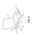
- FIG. 4is an illustration of the power supply station showing the cradle in the reclined position.
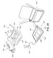
- FIG. 6is an exploded illustration of the power supply station and laptop.
- FIG. 11is an illustration showing the cradle incorporated into a laptop bag.
- FIG. 14is various illustrations showing potential coil arrangements in the handheld cradle and handheld device.
- FIG. 17is illustrations of an adjustable-height desktop pedestal.
- FIG. 19is an illustration of a plurality of alternative desktop panels.
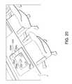
- FIG. 20is an illustration of a second alternative desktop panel.
- FIG. 22is an illustration of a laptop situated on a flexible desktop mat.
- the present inventionrelates to the wireless supply of power to electronic devices using inductive coupling.
- the power supplied through the present inventionmay be used to power the electronic device and/or to charge the device's internal batteries.
- FIG. 2is an illustration showing a laptop solution in which the various data communication and power supply are achieved wirelessly.
- the mouse, keyboard and monitorare wirelessly connected to the laptop using BluetoothTM technology, and the network and printer are connected using WiFi technology. Neither of these wireless data technologies provides a solution for wirelessly powering the laptop.
- eCoupledTM technologycan be used to supply power to the laptop using inductive coupling.
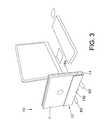
- FIGS. 3-14An inductive power supply station 10 with integrated power supply circuitry and inductive primary coils is shown in FIGS. 3-14 .
- the illustrated power supply stationin intended for use in both upright and horizontal orientations.
- power supply station 10supports the laptop L, for example, while the laptop batteries (not shown) are being charged (See FIG. 3 ).
- the power supply station 10may act something like a CPU stand enabling a cleaner desktop and maintaining easy access to the laptop's ports and CD/DVD player.
- the power supply station 10provides a pedestal that permits the laptop L to receive power inductively while the laptop L is in use (See FIG. 4 ).
- the power supply station 10may, as shown, approximate the size of a standard laptop to provide easier portability, additional laptop protection, easy opportunity charging and improved ergonomics away from the home base. In the reclined (or inclined) position, the power supply station 10 improves screen height and raises the typing surface.
- the primary coilsare arranged to provide power transfer from inside (upright position) or outside (inclined position) the power supply station 10 .
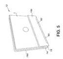
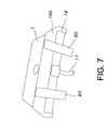
- the power supply station 10generally includes a cradle 12 and a power supply 14 (See FIGS. 5-8 ).
- the power supply 14is housed in a housing 20 located within the cradle 12 .
- the housing 20may be a generally rectangular box of sufficient size to contain the power supply circuitry (not shown).
- the power supply 14may include a conventional AC power plug (not shown) and cord 17 (See FIG. 7 ) for receiving power from a conventional AC power outlet.
- the power supply 14includes circuitry for transforming the input power so that it is suitable for application to one or more inductive primaries, such as primary coils.
- the primariesmay be primary coils that are embedded within or mounted upon a surface of the wall 16 a .
- the number, size, shape and configuration of primarieswill vary from application to application.
- the primarieswill be arranged to align with secondaries located in the laptop or other electronic devices intended for use with the cradle 12 .
- wall 16 bfunctions both as a catch for holding the laptop L in the upright position and as a rest for supporting the cradle 12 when in the reclined position.
- the size, shape and configuration of wall 16 bmay vary from application to application as desired.
- one or more primariesmay be incorporated into wall 16 b , if desired.
- the cradle 12may also include swiveling feet 60 that can be swiveled out to support the cradle 12 in the upright position or swiveled in so that they are out of the way when the cradle 16 is in the reclined position.
- the power supply station 10may incorporate three-phase inductive power technology.
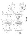
- FIGS. 8-10show a variety of optional primary coil arrangements suitable for use with a three-phase inductive power supply system.
- the wall 16 amay include three large, roughly centrally located coils 32 to provide three-phase inductive power to the laptop L, as well as a plurality of smaller three-coil sets 34 to provide three-phase power to a plurality of other electronic devices D (such as hand held electronic devices).
- the coils 32 and 34generate an inductive field that will power an electronic device located on either side of wall 16 a .
- the wall 16 ais manufactured from materials that provide minimal interference with the inductive field generated by the coils 32 and 34 .
- the primary coils 32may be arranged in a row along the centerline of wall 16 a . If it is desirable to permit the laptop L to receive power in only a single orientation, the coils 32 can be shifted above or below the centerline.
- FIG. 9illustrates, among other things, the placement of portable electronic devices D 1 and D 2 in a cradle 12 having a specific coil arrangement. The position of the coils may vary and, accordingly, the position of the devices D 1 and D 2 may also vary.
- the power supply station 10may be located within a laptop bag B.
- the power supply station 10may be permanently or removably fitted into the laptop bag B.
- the laptop Lmay be fitted into the cradle 12 and a pair of devices D 1 and D 2 may be placed in pockets P within the bag B that are adjacent to coils sets 34 .
- This configurationpermits the laptop L and at least two remote devices D 1 and D 2 to be powered while contained within the bag B.
- This aspect of the present inventionpermits a user to charge the laptop L and handheld devices D 1 and D 2 while they remain stored in the bag B. This can enable “opportunity charging”—the ability of a user to plug in the power supply station 10 whenever the opportunity arises with the hassle of traditional chargers.
- FIG. 12Additional illustrations of the cradle 12 located within a laptop bag B are shown in FIG. 12 .
- One or more centering/locating magnetsmay be incorporated into the device D 1 and the wall 16 a to draw the device D 1 into proper alignment with the coil set 34 .
- the handheld cradlemay be essentially a scaled-down, standalone version of power supply station 10 having its own power supply circuitry (not shown) and power cord (not shown).
- the handheld cradlemay be configured to receive power from the laptop cradle 12 .
- handheld cradles 92 ′may receive power from the laptop cradle 12 in a variety of ways.
- the laptop cradle 12may supply 120V AC to one or more handheld cradles 92 ′ via a cord 94 .
- the handheld cradles 92 ′include circuitry (not shown) for converting the input power for inductive transfer.
- the power supply circuitry of the laptop cradle 12may convert the power and directly power primary coils (not shown) contained within the handheld cradles 92 ′. This alternative eliminates the need for separate power supply circuitry in the handheld cradles 92 ′. Power may alternatively be conveyed to the handheld cradles 92 ′ wirelessly.
- the laptop cradle 12 and handheld cradle 92may include a pair of inductive coils 96 and 98 for transferring power from the laptop cradle 12 to the handheld cradle 92 .
- the handheld cradles 92may not include any internal circuitry and may instead function simply to locate the handheld devices within sufficient proximity to primary coils 99 in the laptop cradle 12 .
- FIG. 16shows a variety of alternative power supply stations, each of which will be described in more detail below.
- FIG. 16shows power supply stations incorporated into an adjustable height desktop pedestal 202 , various desktop panels 240 and 250 , a flexible mat 272 and a power brick 280 .
- FIGS. 20 and 21show another alternative panel embodiment.
- the desktop panel 250is large enough to accommodate a laptop L and one or more additional handheld devices D 4 .
- the panel 250is incorporated directly into the table top T, and is not readily removable (although it alternatively could be separate from the table top T or removable).
- the panel 250may include a central laptop region 252 and a peripheral accessory region 254 .
- the laptop region 252may include a plurality of primary coils 256 a - c that offer laptop placement options within the laptop region 252 . Alternatively, the multiple coils can be provided to allow multi-phase inductive coupling.
- the peripheral region 254may include one or more primary coils 256 d that provide one or more wireless power regions for additional electronic devices, such as handheld device.
- Panel 250may include an indicator light to provide a visual indication when the laptop and/or handheld device is properly coupled.
- the panel 250may include separate indicator lights 258 a - b for the laptop and the handheld device, and the lights 258 a - b are incorporated into the table top T.
- a plurality of panels 250can be incorporated into a single table top T, if desired.
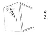
- FIGS. 22 and 23show another alternative embodiment in which the power supply station 270 is incorporated into a flexible power mat 272 .
- the power supply station 270generally includes a flexible mat 272 (hidden below laptop L in FIG. 22 ) and a rigid power supply circuitry housing 274 .
- the mat 272may be coextensive with the laptop L (when unrolled) and may include one or more flexible primary coils (not shown) incorporated into or mounted upon a flexible substrate material. The size, shape and arrangement of primary coils may vary from application to application. The primary coil or coils may be printed on the flexible substrate material.
- the power supply circuitry(not shown) may be incorporated into the power supply circuitry housing 274 .
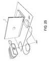
- the power supply station 280includes a single power block 280 that can be positioned adjacent to a laptop L or other electronic device to provide wireless power (See FIG. 24 ).
- the power block 280includes the power supply circuitry (not shown) and one or more primary coils (not shown).
- the power block 280may be positioned adjacent to a secondary coil (not shown) on the laptop or other electronic device to establish an inductive connection (See FIGS. 25 and 26 ).
- the power block 280 and the laptop Linclude locating magnets 282 that draw the power block 280 into optimal alignment with the secondary coil (not shown).
- the laptop L and power block 280may be printed with matching graphics 283 to help locate the proper position for the power block 280 (See FIG. 25 ).
- the power block 280may include an indicator light 284 to provide visual indication when an acceptable inductive coupling has been established (See FIG. 26 ).
- each item of luggagemay include a primary coil 306 that is located adjacent to a pocket or a series of pockets or to a compartment suitable for storing one or more electronic devices.
- the primary coil 306can be sewn into the item of luggage.
- the power supply circuitry(not shown) is housed at any convenient location with the luggage.
- An electrical cord 307is provided to connect the power supply station to standard wall power.
- the cord 307may be retractable.
- the cord 307may be mounted on a conventional take-up reel.
- the power supply station 330is incorporated into a removable carrying case panel 332 (See FIG. 28 ).
- the panel 332may be removable attached to the carrying case 334 , for example, by a zipper 336 .
- the panel 332may include a plurality of pockets 338 and a primary coil 340 .
- the power supply circuitry(not shown) may be disposed within a pocket on the removable panel 332 or it may be housed within a brick (not shown) located along the cord 342 between the panel 332 and the wall plug 343 .
- FIG. 29shows an alternative power supply station 10 ′ having a laptop cradle 12 ′ intended for use in both upright and reclined positions.
- the power supply station 10 ′may include a wall bracket 13 ′ for mounting the laptop cradle 12 ′ to the wall in an upright position.
- FIG. 29also shows an alternative power supply station 400 having a desktop pedestal 402 with a base 404 and an adjustable support surface 406 .
- the support surface 406is coupled to the base 404 by a hinge 408 . As shown, the support surface 406 may be raised or lowered to hold the laptop L in the desired position.
- One or more primary coilsmay be mounted to or embedded within the support surface 406 .
- the power supply circuitry(not shown) may be incorporated into the base 404 or into a brick (not shown) located along the power cord (not shown) for the power supply station 400 .
- FIG. 29shows an alternative embodiment of power supply station 10 ′′ in which the shorter wall 16 b ′′ of the cradle 12 ′′ is angled to facilitate use in the reclined position.
- the angled wall 16 b ′′is oriented to lie along a horizontal surface when the cradle 12 ′′ is place in the reclined position.
Landscapes
- Engineering & Computer Science (AREA)
- Theoretical Computer Science (AREA)
- Power Engineering (AREA)
- General Engineering & Computer Science (AREA)
- General Physics & Mathematics (AREA)
- Physics & Mathematics (AREA)
- Computer Networks & Wireless Communication (AREA)
- Computer Hardware Design (AREA)
- Human Computer Interaction (AREA)
- Quality & Reliability (AREA)
- Signal Processing (AREA)
- Charge And Discharge Circuits For Batteries Or The Like (AREA)
- Power Sources (AREA)
Abstract
Description
Claims (19)
Priority Applications (1)
| Application Number | Priority Date | Filing Date | Title |
|---|---|---|---|
| US12/252,778US8164222B2 (en) | 2007-10-17 | 2008-10-16 | Laptop and portable electronic device wireless power supply systems |
Applications Claiming Priority (2)
| Application Number | Priority Date | Filing Date | Title |
|---|---|---|---|
| US99926307P | 2007-10-17 | 2007-10-17 | |
| US12/252,778US8164222B2 (en) | 2007-10-17 | 2008-10-16 | Laptop and portable electronic device wireless power supply systems |
Publications (2)
| Publication Number | Publication Date |
|---|---|
| US20090106567A1 US20090106567A1 (en) | 2009-04-23 |
| US8164222B2true US8164222B2 (en) | 2012-04-24 |
Family
ID=40351633
Family Applications (1)
| Application Number | Title | Priority Date | Filing Date |
|---|---|---|---|
| US12/252,778Expired - Fee RelatedUS8164222B2 (en) | 2007-10-17 | 2008-10-16 | Laptop and portable electronic device wireless power supply systems |
Country Status (13)
| Country | Link |
|---|---|
| US (1) | US8164222B2 (en) |
| EP (1) | EP2212756B1 (en) |
| JP (1) | JP5363494B2 (en) |
| KR (1) | KR101471696B1 (en) |
| CN (1) | CN101828157B (en) |
| AT (1) | ATE523835T1 (en) |
| AU (1) | AU2008312563A1 (en) |
| CA (1) | CA2701394A1 (en) |
| NZ (1) | NZ584456A (en) |
| PL (1) | PL2212756T3 (en) |
| RU (1) | RU2493579C2 (en) |
| TW (1) | TWI487237B (en) |
| WO (1) | WO2009052167A2 (en) |
Cited By (34)
| Publication number | Priority date | Publication date | Assignee | Title |
|---|---|---|---|---|
| US20110260681A1 (en)* | 2010-04-27 | 2011-10-27 | Guccione Darren S | Portable Wireless Charging Device |
| US20130038138A1 (en)* | 2008-01-14 | 2013-02-14 | Qualcomm Incorporated | Wireless powering and charging station |
| US20130113423A1 (en)* | 2009-01-06 | 2013-05-09 | Access Business Group International Llc | Inductive power supply |
| US8638552B1 (en)* | 2011-05-18 | 2014-01-28 | Erick N. Tuero | Docking station for a Macintosh laptop computer |
| US8926414B1 (en)* | 2013-03-15 | 2015-01-06 | Chad Kirkpatrick | Apparatus for supporting and cooling an electronic device |
| US9281701B2 (en) | 2012-11-16 | 2016-03-08 | Ati Technologies Ulc | Wireless power transfer device for charging mobile/portable devices |
| US9306633B2 (en) | 2011-01-03 | 2016-04-05 | Samsung Electronics Co., Ltd. | Wireless power transmission apparatus and system for wireless power transmission thereof |
| US9312709B2 (en) | 2013-06-24 | 2016-04-12 | Sony Corporation | Charging stand |
| US20160195909A1 (en)* | 2015-01-07 | 2016-07-07 | Dell Products L.P. | Partitioned Airflow Method for Cooling Information Handling Systems |
| US9543780B2 (en) | 2013-06-18 | 2017-01-10 | Alvin Felix Ho | Modular wireless charging station and assembly |
| US9642219B2 (en) | 2014-06-05 | 2017-05-02 | Steelcase Inc. | Environment optimization for space based on presence and activities |
| US9852388B1 (en) | 2014-10-03 | 2017-12-26 | Steelcase, Inc. | Method and system for locating resources and communicating within an enterprise |
| US9921726B1 (en) | 2016-06-03 | 2018-03-20 | Steelcase Inc. | Smart workstation method and system |
| US9955318B1 (en) | 2014-06-05 | 2018-04-24 | Steelcase Inc. | Space guidance and management system and method |
| US10161752B1 (en) | 2014-10-03 | 2018-12-25 | Steelcase Inc. | Method and system for locating resources and communicating within an enterprise |
| US10264213B1 (en) | 2016-12-15 | 2019-04-16 | Steelcase Inc. | Content amplification system and method |
| US10283952B2 (en) | 2017-06-22 | 2019-05-07 | Bretford Manufacturing, Inc. | Rapidly deployable floor power system |
| US10353664B2 (en) | 2014-03-07 | 2019-07-16 | Steelcase Inc. | Method and system for facilitating collaboration sessions |
| US10433646B1 (en) | 2014-06-06 | 2019-10-08 | Steelcaase Inc. | Microclimate control systems and methods |
| US10463572B2 (en) | 2017-07-07 | 2019-11-05 | Neuroderm, Ltd. | Device for subcutaneous delivery of fluid medicament |
| US10614694B1 (en) | 2014-06-06 | 2020-04-07 | Steelcase Inc. | Powered furniture assembly |
| US10733371B1 (en) | 2015-06-02 | 2020-08-04 | Steelcase Inc. | Template based content preparation system for use with a plurality of space types |
| US20210391757A1 (en)* | 2019-02-28 | 2021-12-16 | Denso Corporation | Dynamic wireless power transfer system |
| US11321643B1 (en) | 2014-03-07 | 2022-05-03 | Steelcase Inc. | Method and system for facilitating collaboration sessions |
| US11485494B2 (en) | 2019-10-04 | 2022-11-01 | Northeastern University | Wireless charging of unmanned aerial vehicles |
| USD971832S1 (en) | 2020-10-09 | 2022-12-06 | ACCO Brands Corporation | Combined electronic device charger and stand |
| US20230035566A1 (en)* | 2021-07-30 | 2023-02-02 | Super Group Semiconductor Co., Ltd. | Wireless charging system and its charging station |
| USD979280S1 (en) | 2019-05-28 | 2023-02-28 | Norman R. Byrne | Drape-over article with storage |
| US11744376B2 (en) | 2014-06-06 | 2023-09-05 | Steelcase Inc. | Microclimate control systems and methods |
| US11779697B2 (en) | 2017-07-07 | 2023-10-10 | Neuroderm, Ltd. | Device for subcutaneous delivery of fluid medicament |
| US11799320B2 (en) | 2020-05-01 | 2023-10-24 | Honda Motor Co., Ltd. | Multi-device wireless devices, systems, and methods of use thereof |
| US11984739B1 (en) | 2020-07-31 | 2024-05-14 | Steelcase Inc. | Remote power systems, apparatus and methods |
| US12118178B1 (en) | 2020-04-08 | 2024-10-15 | Steelcase Inc. | Wayfinding services method and apparatus |
| US12137782B2 (en) | 2022-01-14 | 2024-11-12 | Targus International Llc | Laptop lift case |
Families Citing this family (91)
| Publication number | Priority date | Publication date | Assignee | Title |
|---|---|---|---|---|
| US7065658B1 (en) | 2001-05-18 | 2006-06-20 | Palm, Incorporated | Method and apparatus for synchronizing and recharging a connector-less portable computer system |
| US7609512B2 (en)* | 2001-11-19 | 2009-10-27 | Otter Products, Llc | Protective enclosure for electronic device |
| US11201500B2 (en) | 2006-01-31 | 2021-12-14 | Mojo Mobility, Inc. | Efficiencies and flexibilities in inductive (wireless) charging |
| KR20100061845A (en)* | 2007-09-25 | 2010-06-09 | 파우워매트 엘티디. | Adjustable inductive power transmission platform |
| EP2424189A3 (en)* | 2007-10-15 | 2012-06-13 | Penango, Inc. | Methods and systems for encouraging secure communications |
| US8193769B2 (en)* | 2007-10-18 | 2012-06-05 | Powermat Technologies, Ltd | Inductively chargeable audio devices |
| US8633616B2 (en)* | 2007-12-21 | 2014-01-21 | Cynetic Designs Ltd. | Modular pocket with inductive power and data |
| US20110050164A1 (en) | 2008-05-07 | 2011-03-03 | Afshin Partovi | System and methods for inductive charging, and improvements and uses thereof |
| USD640976S1 (en) | 2008-08-28 | 2011-07-05 | Hewlett-Packard Development Company, L.P. | Support structure and/or cradle for a mobile computing device |
| US8234509B2 (en)* | 2008-09-26 | 2012-07-31 | Hewlett-Packard Development Company, L.P. | Portable power supply device for mobile computing devices |
| US8527688B2 (en)* | 2008-09-26 | 2013-09-03 | Palm, Inc. | Extending device functionality amongst inductively linked devices |
| US8850045B2 (en) | 2008-09-26 | 2014-09-30 | Qualcomm Incorporated | System and method for linking and sharing resources amongst devices |
| US20110106954A1 (en)* | 2008-09-26 | 2011-05-05 | Manjirnath Chatterjee | System and method for inductively pairing devices to share data or resources |
| US8868939B2 (en) | 2008-09-26 | 2014-10-21 | Qualcomm Incorporated | Portable power supply device with outlet connector |
| US8688037B2 (en)* | 2008-09-26 | 2014-04-01 | Hewlett-Packard Development Company, L.P. | Magnetic latching mechanism for use in mating a mobile computing device to an accessory device |
| US8712324B2 (en) | 2008-09-26 | 2014-04-29 | Qualcomm Incorporated | Inductive signal transfer system for computing devices |
| US8385822B2 (en)* | 2008-09-26 | 2013-02-26 | Hewlett-Packard Development Company, L.P. | Orientation and presence detection for use in configuring operations of computing devices in docked environments |
| US8401469B2 (en)* | 2008-09-26 | 2013-03-19 | Hewlett-Packard Development Company, L.P. | Shield for use with a computing device that receives an inductive signal transmission |
| US9083686B2 (en)* | 2008-11-12 | 2015-07-14 | Qualcomm Incorporated | Protocol for program during startup sequence |
| WO2010078557A2 (en)* | 2009-01-05 | 2010-07-08 | Palm, Inc. | Interior connector scheme for accessorizing a mobile computing device with a removeable housing segment |
| US9407327B2 (en)* | 2009-02-13 | 2016-08-02 | Qualcomm Incorporated | Wireless power for chargeable and charging devices |
| US9124308B2 (en) | 2009-05-12 | 2015-09-01 | Kimball International, Inc. | Furniture with wireless power |
| WO2010132578A1 (en) | 2009-05-12 | 2010-11-18 | Kimball International, Inc. | Furniture with wireless power |
| US20100308187A1 (en)* | 2009-06-04 | 2010-12-09 | Pi-Fen Lin | Integrated magnetic device and a magnetic board thereof |
| US8437695B2 (en)* | 2009-07-21 | 2013-05-07 | Hewlett-Packard Development Company, L.P. | Power bridge circuit for bi-directional inductive signaling |
| US9395827B2 (en)* | 2009-07-21 | 2016-07-19 | Qualcomm Incorporated | System for detecting orientation of magnetically coupled devices |
| US8954001B2 (en)* | 2009-07-21 | 2015-02-10 | Qualcomm Incorporated | Power bridge circuit for bi-directional wireless power transmission |
| US9312728B2 (en)* | 2009-08-24 | 2016-04-12 | Access Business Group International Llc | Physical and virtual identification in a wireless power network |
| US8755815B2 (en) | 2010-08-31 | 2014-06-17 | Qualcomm Incorporated | Use of wireless access point ID for position determination |
| US8395547B2 (en) | 2009-08-27 | 2013-03-12 | Hewlett-Packard Development Company, L.P. | Location tracking for mobile computing device |
| USD674391S1 (en) | 2009-11-17 | 2013-01-15 | Hewlett-Packard Development Company, L.P. | Docking station for a computing device |
| EP2519424A2 (en)* | 2009-12-28 | 2012-11-07 | Toyoda Gosei Co., Ltd. | Recharging or connection tray for portable electronic devices |
| EP2529469B1 (en)* | 2010-01-27 | 2017-06-14 | Cynetic Designs Ltd | Modular pocket with inductive power and data |
| TWI405925B (en)* | 2010-02-10 | 2013-08-21 | Tennrich Int Corp | Flexible placement |
| US8741403B2 (en)* | 2010-03-19 | 2014-06-03 | Tennrich International Corp. | Flexible disposition apparatus |
| US20150212544A1 (en)* | 2010-03-19 | 2015-07-30 | Shih-Hui Chen | Mounting Apparatus For Auxiliary Device |
| KR101718723B1 (en)* | 2010-04-08 | 2017-03-22 | 삼성전자주식회사 | Laptop computer system with wireless power transform function |
| US20110301425A1 (en)* | 2010-06-03 | 2011-12-08 | Alcon Research, Ltd. | Inductive Task Light For Surgical Console |
| WO2011156768A2 (en) | 2010-06-11 | 2011-12-15 | Mojo Mobility, Inc. | System for wireless power transfer that supports interoperability, and multi-pole magnets for use therewith |
| CN103222319B (en) | 2010-09-29 | 2016-08-10 | 高通股份有限公司 | A kind of method for mobile computing device and mobile computing device |
| US8952571B2 (en)* | 2010-11-05 | 2015-02-10 | Intel Corporation | Extendable wireless power delivery for small devices |
| EP2472697A1 (en)* | 2010-12-31 | 2012-07-04 | Primax Electronics Ltd | Wireless charging transmitter for portable electronic device |
| US8948692B2 (en) | 2011-02-08 | 2015-02-03 | Qualcomm Incorporated | Graphic notification feedback for indicating inductive coupling amongst devices |
| WO2012109364A2 (en)* | 2011-02-08 | 2012-08-16 | Hewlett-Packard Development Company, L.P. | Graphic notification feedback for indicating inductive coupling amongst devices |
| US9041359B2 (en) | 2011-03-10 | 2015-05-26 | Samsung Sdi Co., Ltd. | Battery pack with integral non-contact discharging means and electronic device including the same |
| US20120311363A1 (en)* | 2011-05-31 | 2012-12-06 | Nam Yun Kim | Wireless power transmission and charging system, and communication method of wireless power transmission and charging system |
| US8762747B2 (en) | 2011-06-27 | 2014-06-24 | Qualcomm Incorporated | Inductive charging and data transfer for mobile computing devices organized into a mesh network |
| US8898489B2 (en)* | 2011-07-25 | 2014-11-25 | Dell Products L.P. | Information handling system wireless power docking station module with shared power source and wireless peripheral support |
| US8907752B2 (en)* | 2011-09-12 | 2014-12-09 | Justin Richard Wodrich | Integrated inductive charging in protective cover |
| US20130082646A1 (en)* | 2011-09-30 | 2013-04-04 | Microsoft Corporation | Side Charging Inductor |
| LT2625985T (en)* | 2012-02-07 | 2017-10-10 | Kih-Utveckling Ab | Power distribution control of a furniture arrangment |
| KR101406234B1 (en)* | 2012-05-18 | 2014-06-12 | 주식회사 이랜텍 | Wireless charger for smart phone |
| US9325187B2 (en)* | 2012-05-21 | 2016-04-26 | Lg Electronics Inc. | Structure of transmission and reception unit in wireless charging system |
| US9136729B2 (en)* | 2012-06-18 | 2015-09-15 | Black & Decker Inc. | Power tool battery pack wireless charger |
| WO2014089336A1 (en)* | 2012-12-05 | 2014-06-12 | Belkin International Inc. | Portable-computer stand and method of providing the same |
| JP2014143813A (en)* | 2013-01-23 | 2014-08-07 | Panasonic Corp | Non-contact charger |
| US10226571B2 (en) | 2013-03-14 | 2019-03-12 | Carefusion 303, Inc. | Pump segment placement |
| US9468714B2 (en) | 2013-03-14 | 2016-10-18 | Carefusion 303, Inc. | Memory and identification associated with IV set |
| US9522224B2 (en)* | 2013-03-14 | 2016-12-20 | Carefusion 303, Inc. | Inductively powered modular medical device system |
| US9968739B2 (en) | 2013-03-14 | 2018-05-15 | Carefusion 303, Inc. | Rotary valve for a disposable infusion set |
| US20140265611A1 (en)* | 2013-03-14 | 2014-09-18 | Carefusion 303, Inc. | Intelligent Inductive Power System For Medical Device and System |
| US10135304B2 (en)* | 2013-09-05 | 2018-11-20 | Lg Innotek Co., Ltd. | Supporter |
| KR20150052367A (en) | 2013-10-10 | 2015-05-14 | 엘지이노텍 주식회사 | Wireless apparatus for transmitting power |
| KR102182669B1 (en) | 2013-12-16 | 2020-11-26 | 지이 하이브리드 테크놀로지스, 엘엘씨 | Wireless power transmission apparatus enable to be installed at wall |
| TWI539711B (en) | 2014-01-02 | 2016-06-21 | 鴻騰精密科技股份有限公司 | Wireless charging module |
| US10008870B2 (en) | 2014-03-20 | 2018-06-26 | Otter Products, Llc | Powered case for portable electronic device |
| AT515624A1 (en)* | 2014-03-31 | 2015-10-15 | Kny Design Gmbh | System for wireless energy transmission |
| US9698632B2 (en) | 2014-05-09 | 2017-07-04 | Otter Products, Llc | Wireless battery charger and charge-receiving device |
| RU2566792C1 (en)* | 2014-05-23 | 2015-10-27 | Самсунг Электроникс Ко., Лтд. | Mobile communication device with wireless communication unit and wireless energy receiver |
| US10326488B2 (en) | 2015-04-01 | 2019-06-18 | Otter Products, Llc | Electronic device case with inductive coupling features |
| KR200493080Y1 (en)* | 2015-04-10 | 2021-01-27 | 주식회사 엘지유플러스 | Holding module |
| US10056722B1 (en) | 2015-04-26 | 2018-08-21 | Jamal A Ingram | Devices and methods for providing electrical power |
| KR20160129674A (en)* | 2015-04-30 | 2016-11-09 | 제이터치 코포레이션 | Flexible and retractable wireless charging device |
| US10820677B2 (en)* | 2015-06-05 | 2020-11-03 | Sherron M Thomas | Cordless hair dryer with ionizing solution |
| KR101701045B1 (en)* | 2015-06-09 | 2017-01-31 | 삼성전기주식회사 | Coil structure for wireless power transfer and wireless power transmitter comprising thereof |
| US10164468B2 (en)* | 2015-06-16 | 2018-12-25 | Otter Products, Llc | Protective cover with wireless charging feature |
| WO2017034524A1 (en)* | 2015-08-21 | 2017-03-02 | Hewlett-Packard Development Company, L.P. | Stand to accommodate devices for wireless charging background |
| JP2017103858A (en)* | 2015-11-30 | 2017-06-08 | オムロン株式会社 | Contactless power supply system |
| US10432013B2 (en) | 2016-04-06 | 2019-10-01 | Otter Products, Llc | Windshield solar mount assembly |
| WO2018058130A1 (en) | 2016-09-26 | 2018-03-29 | Snap Inc. | Multifunctional case for electronics enabled eyewear |
| FR3057718B1 (en)* | 2016-10-17 | 2020-11-20 | Atv | CHARGING INSTALLATION BY INDUCTION OF AT LEAST ONE ELECTRONIC DEVICE |
| CA3034055A1 (en)* | 2018-02-21 | 2019-08-21 | Wilson Electronics, Llc | Wireless device cradles |
| US10958103B2 (en) | 2018-08-14 | 2021-03-23 | Otter Products, Llc | Stackable battery pack system with wireless charging |
| JP6503503B1 (en)* | 2018-10-12 | 2019-04-17 | エレコム株式会社 | Wireless charger |
| RU2695103C1 (en)* | 2018-10-17 | 2019-07-19 | Федеральное государственное бюджетное образовательное учреждение высшего образования "Национальный исследовательский Мордовский государственный университет им. Н.П. Огарёва" | Self-contained portable device for inductive charging of accumulator battery |
| USD906958S1 (en) | 2019-05-13 | 2021-01-05 | Otter Products, Llc | Battery charger |
| KR102246015B1 (en)* | 2019-12-19 | 2021-04-28 | 삼성전자주식회사 | Protection case of a smart pad interlocking wall pad and a home network system using the same |
| US11296523B2 (en)* | 2019-12-24 | 2022-04-05 | Fli Charge, Llc | Housing for retaining and charging portable chargers |
| EP3940921A1 (en)* | 2020-07-13 | 2022-01-19 | Hilti Aktiengesellschaft | Transmission unit, energy transmission module, energy transmission system and energy transmission and receiving unit |
| US11340656B2 (en)* | 2020-09-29 | 2022-05-24 | Dell Products L.P. | Cradle for an information handling system |
| JP7605052B2 (en)* | 2021-07-08 | 2024-12-24 | トヨタ自動車株式会社 | Power Supply System |
Citations (21)
| Publication number | Priority date | Publication date | Assignee | Title |
|---|---|---|---|---|
| US5666265A (en) | 1996-06-21 | 1997-09-09 | Lutz; Ron E | Portable workstation housing |
| US20030023471A1 (en) | 2001-07-25 | 2003-01-30 | Kettler Edward W. | Method and tool for achieving data consistency in an enterprise resource planning system |
| US20040060687A1 (en) | 2002-09-27 | 2004-04-01 | Moss David William | Versatile and ergonomic heat-dissipating stand for attachment to portable computers |
| US6731071B2 (en) | 1999-06-21 | 2004-05-04 | Access Business Group International Llc | Inductively powered lamp assembly |
| US20040150934A1 (en) | 2003-02-04 | 2004-08-05 | Baarman David W. | Adapter |
| US6803744B1 (en)* | 1999-11-01 | 2004-10-12 | Anthony Sabo | Alignment independent and self aligning inductive power transfer system |
| US20050007067A1 (en) | 1999-06-21 | 2005-01-13 | Baarman David W. | Vehicle interface |
| US20050127869A1 (en) | 2003-12-12 | 2005-06-16 | Microsoft Corporation | Inductive power adapter |
| US20050162824A1 (en) | 2002-05-28 | 2005-07-28 | Eric Thompson | Vertical docking station |
| US20060043927A1 (en) | 2002-09-27 | 2006-03-02 | Splashpower Limited | Retention of rechargeable devices |
| US20060061323A1 (en) | 2002-10-28 | 2006-03-23 | Cheng Lily K | Contact-less power transfer |
| US7076206B2 (en) | 2001-04-20 | 2006-07-11 | Koninklijke Philips Electronics, N.V. | System for wireless transmission of electrical power, a garment, a system of garments and method for the transmission of signals and/or electrical energy |
| US20060205381A1 (en) | 2002-12-16 | 2006-09-14 | Beart Pilgrim G | Adapting portable electrical devices to receive power wirelessly |
| US20070035917A1 (en) | 2005-08-09 | 2007-02-15 | Apple Computer, Inc. | Methods and apparatuses for docking a portable electronic device that has a planar like configuration and that operates in multiple orientations |
| US7198512B1 (en)* | 2003-10-27 | 2007-04-03 | Swiatek John A | Power distribution for luggage |
| US20070182367A1 (en) | 2006-01-31 | 2007-08-09 | Afshin Partovi | Inductive power source and charging system |
| US7278644B2 (en)* | 2003-11-12 | 2007-10-09 | Arthur Villarreal | Portable workspace for laptop computers |
| US7394165B2 (en)* | 2005-10-22 | 2008-07-01 | Jay Schiller | Luggage with power supply circuit |
| US7408324B2 (en) | 2004-10-27 | 2008-08-05 | Access Business Group International Llc | Implement rack and system for energizing implements |
| US7863859B2 (en)* | 2005-06-28 | 2011-01-04 | Cynetic Designs Ltd. | Contactless battery charging apparel |
| US7936147B2 (en) | 2006-10-24 | 2011-05-03 | Hanrim Postech Co., Ltd. | Non-contact charger capable of wireless data and power transmission and related battery pack and mobile device |
Family Cites Families (8)
| Publication number | Priority date | Publication date | Assignee | Title |
|---|---|---|---|---|
| JPH09244769A (en)* | 1996-03-07 | 1997-09-19 | Kyocera Corp | Power supply method for wireless pointing device |
| JP3161388B2 (en)* | 1997-11-05 | 2001-04-25 | 日本電気株式会社 | Docking bay system |
| JP4036813B2 (en)* | 2003-09-30 | 2008-01-23 | シャープ株式会社 | Non-contact power supply system |
| JP2006141170A (en)* | 2004-11-15 | 2006-06-01 | Sharp Corp | Power supply system, power transmission device and power reception device used therefor |
| JP2006230055A (en)* | 2005-02-15 | 2006-08-31 | Olympus Corp | Cradle and cradle system |
| KR100554889B1 (en)* | 2005-03-21 | 2006-03-03 | 주식회사 한림포스텍 | Contactless charging system |
| US8232764B2 (en)* | 2006-03-24 | 2012-07-31 | Kabushiki Kaisha Toshiba | Power receiving device, and electronic apparatus and non-contact charging system using the same |
| RU2306653C1 (en)* | 2006-04-20 | 2007-09-20 | Олег Валерьевич Белянин | Wireless charging system with reverse communication |
- 2008
- 2008-10-15CACA2701394Apatent/CA2701394A1/ennot_activeAbandoned
- 2008-10-15KRKR1020107010633Apatent/KR101471696B1/ennot_activeExpired - Fee Related
- 2008-10-15NZNZ584456Apatent/NZ584456A/ennot_activeIP Right Cessation
- 2008-10-15RURU2010119300/08Apatent/RU2493579C2/ennot_activeIP Right Cessation
- 2008-10-15PLPL08839806Tpatent/PL2212756T3/enunknown
- 2008-10-15AUAU2008312563Apatent/AU2008312563A1/ennot_activeAbandoned
- 2008-10-15WOPCT/US2008/079974patent/WO2009052167A2/enactiveApplication Filing
- 2008-10-15CNCN200880112602.9Apatent/CN101828157B/ennot_activeExpired - Fee Related
- 2008-10-15EPEP08839806Apatent/EP2212756B1/ennot_activeNot-in-force
- 2008-10-15JPJP2010530080Apatent/JP5363494B2/ennot_activeExpired - Fee Related
- 2008-10-15ATAT08839806Tpatent/ATE523835T1/ennot_activeIP Right Cessation
- 2008-10-16USUS12/252,778patent/US8164222B2/ennot_activeExpired - Fee Related
- 2008-10-17TWTW097140091Apatent/TWI487237B/ennot_activeIP Right Cessation
Patent Citations (24)
| Publication number | Priority date | Publication date | Assignee | Title |
|---|---|---|---|---|
| US5666265A (en) | 1996-06-21 | 1997-09-09 | Lutz; Ron E | Portable workstation housing |
| US6731071B2 (en) | 1999-06-21 | 2004-05-04 | Access Business Group International Llc | Inductively powered lamp assembly |
| US20050007067A1 (en) | 1999-06-21 | 2005-01-13 | Baarman David W. | Vehicle interface |
| US6803744B1 (en)* | 1999-11-01 | 2004-10-12 | Anthony Sabo | Alignment independent and self aligning inductive power transfer system |
| US7076206B2 (en) | 2001-04-20 | 2006-07-11 | Koninklijke Philips Electronics, N.V. | System for wireless transmission of electrical power, a garment, a system of garments and method for the transmission of signals and/or electrical energy |
| US20030023471A1 (en) | 2001-07-25 | 2003-01-30 | Kettler Edward W. | Method and tool for achieving data consistency in an enterprise resource planning system |
| US7679902B2 (en)* | 2002-05-28 | 2010-03-16 | Eric Thompson | Vertical docking station |
| US20050162824A1 (en) | 2002-05-28 | 2005-07-28 | Eric Thompson | Vertical docking station |
| US20040060687A1 (en) | 2002-09-27 | 2004-04-01 | Moss David William | Versatile and ergonomic heat-dissipating stand for attachment to portable computers |
| US20060043927A1 (en) | 2002-09-27 | 2006-03-02 | Splashpower Limited | Retention of rechargeable devices |
| US20060061323A1 (en) | 2002-10-28 | 2006-03-23 | Cheng Lily K | Contact-less power transfer |
| US20060205381A1 (en) | 2002-12-16 | 2006-09-14 | Beart Pilgrim G | Adapting portable electrical devices to receive power wirelessly |
| US20040150934A1 (en) | 2003-02-04 | 2004-08-05 | Baarman David W. | Adapter |
| US7198512B1 (en)* | 2003-10-27 | 2007-04-03 | Swiatek John A | Power distribution for luggage |
| US7278644B2 (en)* | 2003-11-12 | 2007-10-09 | Arthur Villarreal | Portable workspace for laptop computers |
| US20050127869A1 (en) | 2003-12-12 | 2005-06-16 | Microsoft Corporation | Inductive power adapter |
| US7378817B2 (en)* | 2003-12-12 | 2008-05-27 | Microsoft Corporation | Inductive power adapter |
| US7408324B2 (en) | 2004-10-27 | 2008-08-05 | Access Business Group International Llc | Implement rack and system for energizing implements |
| US7863859B2 (en)* | 2005-06-28 | 2011-01-04 | Cynetic Designs Ltd. | Contactless battery charging apparel |
| US20070035917A1 (en) | 2005-08-09 | 2007-02-15 | Apple Computer, Inc. | Methods and apparatuses for docking a portable electronic device that has a planar like configuration and that operates in multiple orientations |
| US7352567B2 (en) | 2005-08-09 | 2008-04-01 | Apple Inc. | Methods and apparatuses for docking a portable electronic device that has a planar like configuration and that operates in multiple orientations |
| US7394165B2 (en)* | 2005-10-22 | 2008-07-01 | Jay Schiller | Luggage with power supply circuit |
| US20070182367A1 (en) | 2006-01-31 | 2007-08-09 | Afshin Partovi | Inductive power source and charging system |
| US7936147B2 (en) | 2006-10-24 | 2011-05-03 | Hanrim Postech Co., Ltd. | Non-contact charger capable of wireless data and power transmission and related battery pack and mobile device |
Non-Patent Citations (2)
| Title |
|---|
| International Search Report, International Application No. PCT/US2008/079974, Jun. 30, 2009. |
| Written Opinion of the International Searching Authority, International Application No. PCT/US2008/079974, International Filing Date Oct. 15, 2008. |
Cited By (75)
| Publication number | Priority date | Publication date | Assignee | Title |
|---|---|---|---|---|
| US20130038138A1 (en)* | 2008-01-14 | 2013-02-14 | Qualcomm Incorporated | Wireless powering and charging station |
| US20130113423A1 (en)* | 2009-01-06 | 2013-05-09 | Access Business Group International Llc | Inductive power supply |
| US8890369B2 (en)* | 2009-01-06 | 2014-11-18 | Access Business Group International Llc | Inductive power supply |
| US8629651B2 (en)* | 2010-04-27 | 2014-01-14 | Callpod, Inc. | Portable wireless charging device |
| US20110260681A1 (en)* | 2010-04-27 | 2011-10-27 | Guccione Darren S | Portable Wireless Charging Device |
| US9306633B2 (en) | 2011-01-03 | 2016-04-05 | Samsung Electronics Co., Ltd. | Wireless power transmission apparatus and system for wireless power transmission thereof |
| US8638552B1 (en)* | 2011-05-18 | 2014-01-28 | Erick N. Tuero | Docking station for a Macintosh laptop computer |
| US9281701B2 (en) | 2012-11-16 | 2016-03-08 | Ati Technologies Ulc | Wireless power transfer device for charging mobile/portable devices |
| US8926414B1 (en)* | 2013-03-15 | 2015-01-06 | Chad Kirkpatrick | Apparatus for supporting and cooling an electronic device |
| US9229499B2 (en) | 2013-03-15 | 2016-01-05 | Chad Kirkpatrick | Apparatus for supporting and cooling an electronic device |
| US9543780B2 (en) | 2013-06-18 | 2017-01-10 | Alvin Felix Ho | Modular wireless charging station and assembly |
| US9312709B2 (en) | 2013-06-24 | 2016-04-12 | Sony Corporation | Charging stand |
| US10353664B2 (en) | 2014-03-07 | 2019-07-16 | Steelcase Inc. | Method and system for facilitating collaboration sessions |
| US11321643B1 (en) | 2014-03-07 | 2022-05-03 | Steelcase Inc. | Method and system for facilitating collaboration sessions |
| US11150859B2 (en) | 2014-03-07 | 2021-10-19 | Steelcase Inc. | Method and system for facilitating collaboration sessions |
| US12001976B1 (en) | 2014-03-07 | 2024-06-04 | Steelcase Inc. | Method and system for facilitating collaboration sessions |
| US10057963B2 (en) | 2014-06-05 | 2018-08-21 | Steelcase Inc. | Environment optimization for space based on presence and activities |
| US10561006B2 (en) | 2014-06-05 | 2020-02-11 | Steelcase Inc. | Environment optimization for space based on presence and activities |
| US12324072B2 (en) | 2014-06-05 | 2025-06-03 | Steelcase Inc. | Environment optimization for space based on presence and activities |
| US11085771B1 (en) | 2014-06-05 | 2021-08-10 | Steelcase Inc. | Space guidance and management system and method |
| US11402216B1 (en) | 2014-06-05 | 2022-08-02 | Steelcase Inc. | Space guidance and management system and method |
| US10225707B1 (en) | 2014-06-05 | 2019-03-05 | Steelcase Inc. | Space guidance and management system and method |
| US11402217B1 (en) | 2014-06-05 | 2022-08-02 | Steelcase Inc. | Space guidance and management system and method |
| US11979959B1 (en) | 2014-06-05 | 2024-05-07 | Steelcase Inc. | Environment optimization for space based on presence and activities |
| US12375874B1 (en) | 2014-06-05 | 2025-07-29 | Steelcase Inc. | Space guidance and management system and method |
| US9642219B2 (en) | 2014-06-05 | 2017-05-02 | Steelcase Inc. | Environment optimization for space based on presence and activities |
| US11307037B1 (en) | 2014-06-05 | 2022-04-19 | Steelcase Inc. | Space guidance and management system and method |
| US11280619B1 (en) | 2014-06-05 | 2022-03-22 | Steelcase Inc. | Space guidance and management system and method |
| US11212898B2 (en) | 2014-06-05 | 2021-12-28 | Steelcase Inc. | Environment optimization for space based on presence and activities |
| US9955318B1 (en) | 2014-06-05 | 2018-04-24 | Steelcase Inc. | Space guidance and management system and method |
| US10433646B1 (en) | 2014-06-06 | 2019-10-08 | Steelcaase Inc. | Microclimate control systems and methods |
| US10614694B1 (en) | 2014-06-06 | 2020-04-07 | Steelcase Inc. | Powered furniture assembly |
| US11744376B2 (en) | 2014-06-06 | 2023-09-05 | Steelcase Inc. | Microclimate control systems and methods |
| US10970662B2 (en) | 2014-10-03 | 2021-04-06 | Steelcase Inc. | Method and system for locating resources and communicating within an enterprise |
| US10121113B1 (en) | 2014-10-03 | 2018-11-06 | Steelcase Inc. | Method and system for locating resources and communicating within an enterprise |
| US10161752B1 (en) | 2014-10-03 | 2018-12-25 | Steelcase Inc. | Method and system for locating resources and communicating within an enterprise |
| US9852388B1 (en) | 2014-10-03 | 2017-12-26 | Steelcase, Inc. | Method and system for locating resources and communicating within an enterprise |
| US11687854B1 (en) | 2014-10-03 | 2023-06-27 | Steelcase Inc. | Method and system for locating resources and communicating within an enterprise |
| US11143510B1 (en) | 2014-10-03 | 2021-10-12 | Steelcase Inc. | Method and system for locating resources and communicating within an enterprise |
| US11713969B1 (en) | 2014-10-03 | 2023-08-01 | Steelcase Inc. | Method and system for locating resources and communicating within an enterprise |
| US11168987B2 (en) | 2014-10-03 | 2021-11-09 | Steelcase Inc. | Method and system for locating resources and communicating within an enterprise |
| US9618986B2 (en)* | 2015-01-07 | 2017-04-11 | Dell Products L.P. | Partitioned airflow method for cooling information handling systems |
| US20160195909A1 (en)* | 2015-01-07 | 2016-07-07 | Dell Products L.P. | Partitioned Airflow Method for Cooling Information Handling Systems |
| US11100282B1 (en) | 2015-06-02 | 2021-08-24 | Steelcase Inc. | Template based content preparation system for use with a plurality of space types |
| US10733371B1 (en) | 2015-06-02 | 2020-08-04 | Steelcase Inc. | Template based content preparation system for use with a plurality of space types |
| US12213191B1 (en) | 2016-06-03 | 2025-01-28 | Steelcase Inc. | Smart workstation method and system |
| US11956838B1 (en) | 2016-06-03 | 2024-04-09 | Steelcase Inc. | Smart workstation method and system |
| US10459611B1 (en) | 2016-06-03 | 2019-10-29 | Steelcase Inc. | Smart workstation method and system |
| US11690111B1 (en) | 2016-06-03 | 2023-06-27 | Steelcase Inc. | Smart workstation method and system |
| US11330647B2 (en) | 2016-06-03 | 2022-05-10 | Steelcase Inc. | Smart workstation method and system |
| US9921726B1 (en) | 2016-06-03 | 2018-03-20 | Steelcase Inc. | Smart workstation method and system |
| US10264213B1 (en) | 2016-12-15 | 2019-04-16 | Steelcase Inc. | Content amplification system and method |
| US11190731B1 (en) | 2016-12-15 | 2021-11-30 | Steelcase Inc. | Content amplification system and method |
| US12231810B1 (en) | 2016-12-15 | 2025-02-18 | Steelcase Inc. | Content amplification system and method |
| US10897598B1 (en) | 2016-12-15 | 2021-01-19 | Steelcase Inc. | Content amplification system and method |
| US11652957B1 (en) | 2016-12-15 | 2023-05-16 | Steelcase Inc. | Content amplification system and method |
| US10638090B1 (en) | 2016-12-15 | 2020-04-28 | Steelcase Inc. | Content amplification system and method |
| US10283952B2 (en) | 2017-06-22 | 2019-05-07 | Bretford Manufacturing, Inc. | Rapidly deployable floor power system |
| US10463572B2 (en) | 2017-07-07 | 2019-11-05 | Neuroderm, Ltd. | Device for subcutaneous delivery of fluid medicament |
| US10463787B2 (en) | 2017-07-07 | 2019-11-05 | Neuroderm, Ltd. | Device for subcutaneous delivery of fluid medicament |
| US11779697B2 (en) | 2017-07-07 | 2023-10-10 | Neuroderm, Ltd. | Device for subcutaneous delivery of fluid medicament |
| US11554210B2 (en) | 2017-07-07 | 2023-01-17 | Neuroderm, Ltd. | Device for subcutaneous delivery of fluid medicament |
| US10603430B2 (en) | 2017-07-07 | 2020-03-31 | Neuroderm, Ltd. | Device for subcutaneous delivery of fluid medicament |
| US20210391757A1 (en)* | 2019-02-28 | 2021-12-16 | Denso Corporation | Dynamic wireless power transfer system |
| US12095287B2 (en)* | 2019-02-28 | 2024-09-17 | Denso Corporation | Dynamic wireless power transfer system |
| USD979280S1 (en) | 2019-05-28 | 2023-02-28 | Norman R. Byrne | Drape-over article with storage |
| US12191656B2 (en) | 2019-10-04 | 2025-01-07 | Northeastern University | Wireless charging of unmanned aerial vehicles |
| US11485494B2 (en) | 2019-10-04 | 2022-11-01 | Northeastern University | Wireless charging of unmanned aerial vehicles |
| US12118178B1 (en) | 2020-04-08 | 2024-10-15 | Steelcase Inc. | Wayfinding services method and apparatus |
| US11799320B2 (en) | 2020-05-01 | 2023-10-24 | Honda Motor Co., Ltd. | Multi-device wireless devices, systems, and methods of use thereof |
| US11984739B1 (en) | 2020-07-31 | 2024-05-14 | Steelcase Inc. | Remote power systems, apparatus and methods |
| US12341360B1 (en) | 2020-07-31 | 2025-06-24 | Steelcase Inc. | Remote power systems, apparatus and methods |
| USD971832S1 (en) | 2020-10-09 | 2022-12-06 | ACCO Brands Corporation | Combined electronic device charger and stand |
| US20230035566A1 (en)* | 2021-07-30 | 2023-02-02 | Super Group Semiconductor Co., Ltd. | Wireless charging system and its charging station |
| US12137782B2 (en) | 2022-01-14 | 2024-11-12 | Targus International Llc | Laptop lift case |
Also Published As
| Publication number | Publication date |
|---|---|
| EP2212756A2 (en) | 2010-08-04 |
| CA2701394A1 (en) | 2009-04-23 |
| WO2009052167A2 (en) | 2009-04-23 |
| TW200941891A (en) | 2009-10-01 |
| WO2009052167A4 (en) | 2009-11-12 |
| CN101828157A (en) | 2010-09-08 |
| ATE523835T1 (en) | 2011-09-15 |
| CN101828157B (en) | 2014-08-27 |
| EP2212756B1 (en) | 2011-09-07 |
| KR101471696B1 (en) | 2014-12-10 |
| AU2008312563A1 (en) | 2009-04-23 |
| KR20100085976A (en) | 2010-07-29 |
| US20090106567A1 (en) | 2009-04-23 |
| AU2008312563A2 (en) | 2010-11-18 |
| JP5363494B2 (en) | 2013-12-11 |
| RU2010119300A (en) | 2011-11-27 |
| TWI487237B (en) | 2015-06-01 |
| WO2009052167A3 (en) | 2009-08-27 |
| JP2011501938A (en) | 2011-01-13 |
| RU2493579C2 (en) | 2013-09-20 |
| NZ584456A (en) | 2012-05-25 |
| HK1146422A1 (en) | 2011-06-03 |
| PL2212756T3 (en) | 2012-02-29 |
Similar Documents
| Publication | Publication Date | Title |
|---|---|---|
| US8164222B2 (en) | Laptop and portable electronic device wireless power supply systems | |
| JP2011501938A5 (en) | ||
| US10897149B2 (en) | Storage tote with electrical outlets | |
| CN102640379B (en) | wireless power supply | |
| US20190123577A1 (en) | Inductive Mobile Device Charger | |
| WO2020055560A1 (en) | Induction charging for a portable electronic device with a grip attachment | |
| US20100201201A1 (en) | Wireless power transfer in public places | |
| US10547188B2 (en) | Furniture-mounted charging station | |
| WO2014110156A1 (en) | Wireless energy transfer for promotional items | |
| US8749983B2 (en) | Portable adjunct device for portable electronic devices | |
| US10582768B1 (en) | Working desk with display and carrying bag | |
| US8480191B1 (en) | Storage apparatus | |
| CN211720281U (en) | Mobile power supply | |
| US10973296B2 (en) | Carrying bag capable of prolonging power supply | |
| HK1146422B (en) | Laptop and portable electronic device wireless power supply systems | |
| CN211744151U (en) | Detachable wireless charging seat with storage function | |
| CN207967984U (en) | A kind of mobile phone wireless charging base | |
| CN217642828U (en) | Coaxial type foldable wireless charging seat | |
| KR20200130098A (en) | Card type Wireless Charger | |
| WO2022266722A1 (en) | Portable wireless charging apparatus |
Legal Events
| Date | Code | Title | Description |
|---|---|---|---|
| AS | Assignment | Owner name:ACCESS BUSINESS GROUP INTERNATIONAL LLC, MICHIGAN Free format text:ASSIGNMENT OF ASSIGNORS INTEREST;ASSIGNOR:BAARMAN, DAVID W.;REEL/FRAME:021692/0955 Effective date:20081015 | |
| FEPP | Fee payment procedure | Free format text:PAYOR NUMBER ASSIGNED (ORIGINAL EVENT CODE: ASPN); ENTITY STATUS OF PATENT OWNER: LARGE ENTITY | |
| STCF | Information on status: patent grant | Free format text:PATENTED CASE | |
| FPAY | Fee payment | Year of fee payment:4 | |
| AS | Assignment | Owner name:PHILIPS IP VENTURES B.V., NETHERLANDS Free format text:ASSIGNMENT OF ASSIGNORS INTEREST;ASSIGNOR:ACCESS BUSINESS GROUP INTERNATIONAL LLC;REEL/FRAME:045644/0810 Effective date:20171020 | |
| MAFP | Maintenance fee payment | Free format text:PAYMENT OF MAINTENANCE FEE, 8TH YEAR, LARGE ENTITY (ORIGINAL EVENT CODE: M1552); ENTITY STATUS OF PATENT OWNER: LARGE ENTITY Year of fee payment:8 | |
| FEPP | Fee payment procedure | Free format text:MAINTENANCE FEE REMINDER MAILED (ORIGINAL EVENT CODE: REM.); ENTITY STATUS OF PATENT OWNER: LARGE ENTITY | |
| LAPS | Lapse for failure to pay maintenance fees | Free format text:PATENT EXPIRED FOR FAILURE TO PAY MAINTENANCE FEES (ORIGINAL EVENT CODE: EXP.); ENTITY STATUS OF PATENT OWNER: LARGE ENTITY | |
| STCH | Information on status: patent discontinuation | Free format text:PATENT EXPIRED DUE TO NONPAYMENT OF MAINTENANCE FEES UNDER 37 CFR 1.362 | |
| FP | Lapsed due to failure to pay maintenance fee | Effective date:20240424 |