US8163397B2 - Method and apparatus for providing hermetic electrical feedthrough - Google Patents
Method and apparatus for providing hermetic electrical feedthroughDownload PDFInfo
- Publication number
- US8163397B2 US8163397B2US13/165,388US201113165388AUS8163397B2US 8163397 B2US8163397 B2US 8163397B2US 201113165388 AUS201113165388 AUS 201113165388AUS 8163397 B2US8163397 B2US 8163397B2
- Authority
- US
- United States
- Prior art keywords
- sheet
- mils
- structure according
- hermetic structure
- electrically conductive
- Prior art date
- Legal status (The legal status is an assumption and is not a legal conclusion. Google has not performed a legal analysis and makes no representation as to the accuracy of the status listed.)
- Expired - Fee Related
Links
- 238000000034methodMethods0.000titleabstractdescription16
- BASFCYQUMIYNBI-UHFFFAOYSA-NplatinumChemical compound[Pt]BASFCYQUMIYNBI-UHFFFAOYSA-N0.000claimsabstractdescription30
- TWNQGVIAIRXVLR-UHFFFAOYSA-Noxo(oxoalumanyloxy)alumaneChemical compoundO=[Al]O[Al]=OTWNQGVIAIRXVLR-UHFFFAOYSA-N0.000claimsabstractdescription16
- 229910052697platinumInorganic materials0.000claimsabstractdescription14
- 229910010293ceramic materialInorganic materials0.000claimsdescription12
- 239000004020conductorSubstances0.000claimsdescription12
- MCMNRKCIXSYSNV-UHFFFAOYSA-NZirconium dioxideChemical compoundO=[Zr]=OMCMNRKCIXSYSNV-UHFFFAOYSA-N0.000claimsdescription6
- 239000000203mixtureSubstances0.000claims1
- 239000000919ceramicSubstances0.000abstractdescription39
- 239000000463materialSubstances0.000abstractdescription15
- 238000010304firingMethods0.000abstractdescription9
- 239000007787solidSubstances0.000abstractdescription5
- 238000002513implantationMethods0.000abstractdescription4
- 229910052751metalInorganic materials0.000description6
- 239000002184metalSubstances0.000description6
- 230000006835compressionEffects0.000description5
- 238000007906compressionMethods0.000description5
- 238000013459approachMethods0.000description4
- 238000000429assemblyMethods0.000description3
- 230000000712assemblyEffects0.000description3
- 239000011521glassSubstances0.000description3
- PCHJSUWPFVWCPO-UHFFFAOYSA-NgoldChemical compound[Au]PCHJSUWPFVWCPO-UHFFFAOYSA-N0.000description3
- 239000010931goldSubstances0.000description3
- 229910052737goldInorganic materials0.000description3
- 238000004519manufacturing processMethods0.000description3
- 239000000758substrateSubstances0.000description3
- KDLHZDBZIXYQEI-UHFFFAOYSA-NPalladiumChemical compound[Pd]KDLHZDBZIXYQEI-UHFFFAOYSA-N0.000description2
- RTAQQCXQSZGOHL-UHFFFAOYSA-NTitaniumChemical compound[Ti]RTAQQCXQSZGOHL-UHFFFAOYSA-N0.000description2
- 238000001816coolingMethods0.000description2
- 230000002939deleterious effectEffects0.000description2
- -1e.g.Inorganic materials0.000description2
- 229910052574oxide ceramicInorganic materials0.000description2
- 239000011224oxide ceramicSubstances0.000description2
- 238000005096rolling processMethods0.000description2
- 238000012360testing methodMethods0.000description2
- 229910052719titaniumInorganic materials0.000description2
- 239000010936titaniumSubstances0.000description2
- VEXZGXHMUGYJMC-UHFFFAOYSA-MChloride anionChemical compound[Cl-]VEXZGXHMUGYJMC-UHFFFAOYSA-M0.000description1
- 230000004888barrier functionEffects0.000description1
- 238000005219brazingMethods0.000description1
- 238000005520cutting processMethods0.000description1
- 238000010586diagramMethods0.000description1
- 238000009792diffusion processMethods0.000description1
- 238000003487electrochemical reactionMethods0.000description1
- 238000005530etchingMethods0.000description1
- 238000010438heat treatmentMethods0.000description1
- 229910052734heliumInorganic materials0.000description1
- 239000001307heliumSubstances0.000description1
- SWQJXJOGLNCZEY-UHFFFAOYSA-Nhelium atomChemical compound[He]SWQJXJOGLNCZEY-UHFFFAOYSA-N0.000description1
- XLYOFNOQVPJJNP-UHFFFAOYSA-MhydroxideChemical compound[OH-]XLYOFNOQVPJJNP-UHFFFAOYSA-M0.000description1
- 239000012212insulatorSubstances0.000description1
- 238000001459lithographyMethods0.000description1
- 230000013011matingEffects0.000description1
- 150000002739metalsChemical class0.000description1
- 238000012986modificationMethods0.000description1
- 230000004048modificationEffects0.000description1
- 229910052758niobiumInorganic materials0.000description1
- 239000010955niobiumSubstances0.000description1
- GUCVJGMIXFAOAE-UHFFFAOYSA-Nniobium atomChemical compound[Nb]GUCVJGMIXFAOAE-UHFFFAOYSA-N0.000description1
- 229910052763palladiumInorganic materials0.000description1
- 229920005596polymer binderPolymers0.000description1
- 239000002491polymer binding agentSubstances0.000description1
- 238000012545processingMethods0.000description1
- 230000000284resting effectEffects0.000description1
- 238000007789sealingMethods0.000description1
- 239000002002slurrySubstances0.000description1
- 239000000725suspensionSubstances0.000description1
- 229910052715tantalumInorganic materials0.000description1
- GUVRBAGPIYLISA-UHFFFAOYSA-Ntantalum atomChemical compound[Ta]GUVRBAGPIYLISA-UHFFFAOYSA-N0.000description1
- 238000003466weldingMethods0.000description1
- 238000009736wettingMethods0.000description1
Images


Classifications
- H—ELECTRICITY
- H05—ELECTRIC TECHNIQUES NOT OTHERWISE PROVIDED FOR
- H05K—PRINTED CIRCUITS; CASINGS OR CONSTRUCTIONAL DETAILS OF ELECTRIC APPARATUS; MANUFACTURE OF ASSEMBLAGES OF ELECTRICAL COMPONENTS
- H05K3/00—Apparatus or processes for manufacturing printed circuits
- H05K3/40—Forming printed elements for providing electric connections to or between printed circuits
- H05K3/4038—Through-connections; Vertical interconnect access [VIA] connections
- H05K3/4046—Through-connections; Vertical interconnect access [VIA] connections using auxiliary conductive elements, e.g. metallic spheres, eyelets, pieces of wire
- H—ELECTRICITY
- H01—ELECTRIC ELEMENTS
- H01L—SEMICONDUCTOR DEVICES NOT COVERED BY CLASS H10
- H01L21/00—Processes or apparatus adapted for the manufacture or treatment of semiconductor or solid state devices or of parts thereof
- H01L21/02—Manufacture or treatment of semiconductor devices or of parts thereof
- H01L21/04—Manufacture or treatment of semiconductor devices or of parts thereof the devices having potential barriers, e.g. a PN junction, depletion layer or carrier concentration layer
- H01L21/48—Manufacture or treatment of parts, e.g. containers, prior to assembly of the devices, using processes not provided for in a single one of the groups H01L21/18 - H01L21/326 or H10D48/04 - H10D48/07
- H01L21/4814—Conductive parts
- H01L21/4846—Leads on or in insulating or insulated substrates, e.g. metallisation
- H01L21/486—Via connections through the substrate with or without pins
- H—ELECTRICITY
- H01—ELECTRIC ELEMENTS
- H01L—SEMICONDUCTOR DEVICES NOT COVERED BY CLASS H10
- H01L23/00—Details of semiconductor or other solid state devices
- H01L23/02—Containers; Seals
- H01L23/10—Containers; Seals characterised by the material or arrangement of seals between parts, e.g. between cap and base of the container or between leads and walls of the container
- H—ELECTRICITY
- H01—ELECTRIC ELEMENTS
- H01L—SEMICONDUCTOR DEVICES NOT COVERED BY CLASS H10
- H01L2924/00—Indexing scheme for arrangements or methods for connecting or disconnecting semiconductor or solid-state bodies as covered by H01L24/00
- H01L2924/0001—Technical content checked by a classifier
- H01L2924/0002—Not covered by any one of groups H01L24/00, H01L24/00 and H01L2224/00
- H—ELECTRICITY
- H05—ELECTRIC TECHNIQUES NOT OTHERWISE PROVIDED FOR
- H05K—PRINTED CIRCUITS; CASINGS OR CONSTRUCTIONAL DETAILS OF ELECTRIC APPARATUS; MANUFACTURE OF ASSEMBLAGES OF ELECTRICAL COMPONENTS
- H05K1/00—Printed circuits
- H05K1/02—Details
- H05K1/03—Use of materials for the substrate
- H05K1/0306—Inorganic insulating substrates, e.g. ceramic, glass
- H—ELECTRICITY
- H05—ELECTRIC TECHNIQUES NOT OTHERWISE PROVIDED FOR
- H05K—PRINTED CIRCUITS; CASINGS OR CONSTRUCTIONAL DETAILS OF ELECTRIC APPARATUS; MANUFACTURE OF ASSEMBLAGES OF ELECTRICAL COMPONENTS
- H05K2201/00—Indexing scheme relating to printed circuits covered by H05K1/00
- H05K2201/10—Details of components or other objects attached to or integrated in a printed circuit board
- H05K2201/10227—Other objects, e.g. metallic pieces
- H05K2201/10287—Metal wires as connectors or conductors
- H—ELECTRICITY
- H05—ELECTRIC TECHNIQUES NOT OTHERWISE PROVIDED FOR
- H05K—PRINTED CIRCUITS; CASINGS OR CONSTRUCTIONAL DETAILS OF ELECTRIC APPARATUS; MANUFACTURE OF ASSEMBLAGES OF ELECTRICAL COMPONENTS
- H05K2201/00—Indexing scheme relating to printed circuits covered by H05K1/00
- H05K2201/10—Details of components or other objects attached to or integrated in a printed circuit board
- H05K2201/10227—Other objects, e.g. metallic pieces
- H05K2201/10416—Metallic blocks or heatsinks completely inserted in a PCB
- Y—GENERAL TAGGING OF NEW TECHNOLOGICAL DEVELOPMENTS; GENERAL TAGGING OF CROSS-SECTIONAL TECHNOLOGIES SPANNING OVER SEVERAL SECTIONS OF THE IPC; TECHNICAL SUBJECTS COVERED BY FORMER USPC CROSS-REFERENCE ART COLLECTIONS [XRACs] AND DIGESTS
- Y10—TECHNICAL SUBJECTS COVERED BY FORMER USPC
- Y10T—TECHNICAL SUBJECTS COVERED BY FORMER US CLASSIFICATION
- Y10T29/00—Metal working
- Y10T29/49—Method of mechanical manufacture
- Y10T29/49002—Electrical device making
- Y10T29/49117—Conductor or circuit manufacturing
- Y10T29/49124—On flat or curved insulated base, e.g., printed circuit, etc.
- Y10T29/4913—Assembling to base an electrical component, e.g., capacitor, etc.
- Y10T29/49139—Assembling to base an electrical component, e.g., capacitor, etc. by inserting component lead or terminal into base aperture
- Y—GENERAL TAGGING OF NEW TECHNOLOGICAL DEVELOPMENTS; GENERAL TAGGING OF CROSS-SECTIONAL TECHNOLOGIES SPANNING OVER SEVERAL SECTIONS OF THE IPC; TECHNICAL SUBJECTS COVERED BY FORMER USPC CROSS-REFERENCE ART COLLECTIONS [XRACs] AND DIGESTS
- Y10—TECHNICAL SUBJECTS COVERED BY FORMER USPC
- Y10T—TECHNICAL SUBJECTS COVERED BY FORMER US CLASSIFICATION
- Y10T29/00—Metal working
- Y10T29/49—Method of mechanical manufacture
- Y10T29/49002—Electrical device making
- Y10T29/49117—Conductor or circuit manufacturing
- Y10T29/49124—On flat or curved insulated base, e.g., printed circuit, etc.
- Y10T29/4913—Assembling to base an electrical component, e.g., capacitor, etc.
- Y10T29/49146—Assembling to base an electrical component, e.g., capacitor, etc. with encapsulating, e.g., potting, etc.
- Y—GENERAL TAGGING OF NEW TECHNOLOGICAL DEVELOPMENTS; GENERAL TAGGING OF CROSS-SECTIONAL TECHNOLOGIES SPANNING OVER SEVERAL SECTIONS OF THE IPC; TECHNICAL SUBJECTS COVERED BY FORMER USPC CROSS-REFERENCE ART COLLECTIONS [XRACs] AND DIGESTS
- Y10—TECHNICAL SUBJECTS COVERED BY FORMER USPC
- Y10T—TECHNICAL SUBJECTS COVERED BY FORMER US CLASSIFICATION
- Y10T29/00—Metal working
- Y10T29/49—Method of mechanical manufacture
- Y10T29/49002—Electrical device making
- Y10T29/49117—Conductor or circuit manufacturing
- Y10T29/49124—On flat or curved insulated base, e.g., printed circuit, etc.
- Y10T29/49147—Assembling terminal to base
- Y—GENERAL TAGGING OF NEW TECHNOLOGICAL DEVELOPMENTS; GENERAL TAGGING OF CROSS-SECTIONAL TECHNOLOGIES SPANNING OVER SEVERAL SECTIONS OF THE IPC; TECHNICAL SUBJECTS COVERED BY FORMER USPC CROSS-REFERENCE ART COLLECTIONS [XRACs] AND DIGESTS
- Y10—TECHNICAL SUBJECTS COVERED BY FORMER USPC
- Y10T—TECHNICAL SUBJECTS COVERED BY FORMER US CLASSIFICATION
- Y10T29/00—Metal working
- Y10T29/49—Method of mechanical manufacture
- Y10T29/49002—Electrical device making
- Y10T29/49117—Conductor or circuit manufacturing
- Y10T29/49124—On flat or curved insulated base, e.g., printed circuit, etc.
- Y10T29/49155—Manufacturing circuit on or in base
- Y10T29/49162—Manufacturing circuit on or in base by using wire as conductive path
- Y—GENERAL TAGGING OF NEW TECHNOLOGICAL DEVELOPMENTS; GENERAL TAGGING OF CROSS-SECTIONAL TECHNOLOGIES SPANNING OVER SEVERAL SECTIONS OF THE IPC; TECHNICAL SUBJECTS COVERED BY FORMER USPC CROSS-REFERENCE ART COLLECTIONS [XRACs] AND DIGESTS
- Y10—TECHNICAL SUBJECTS COVERED BY FORMER USPC
- Y10T—TECHNICAL SUBJECTS COVERED BY FORMER US CLASSIFICATION
- Y10T29/00—Metal working
- Y10T29/49—Method of mechanical manufacture
- Y10T29/49002—Electrical device making
- Y10T29/49117—Conductor or circuit manufacturing
- Y10T29/49124—On flat or curved insulated base, e.g., printed circuit, etc.
- Y10T29/49155—Manufacturing circuit on or in base
- Y10T29/49163—Manufacturing circuit on or in base with sintering of base
- Y—GENERAL TAGGING OF NEW TECHNOLOGICAL DEVELOPMENTS; GENERAL TAGGING OF CROSS-SECTIONAL TECHNOLOGIES SPANNING OVER SEVERAL SECTIONS OF THE IPC; TECHNICAL SUBJECTS COVERED BY FORMER USPC CROSS-REFERENCE ART COLLECTIONS [XRACs] AND DIGESTS
- Y10—TECHNICAL SUBJECTS COVERED BY FORMER USPC
- Y10T—TECHNICAL SUBJECTS COVERED BY FORMER US CLASSIFICATION
- Y10T428/00—Stock material or miscellaneous articles
- Y10T428/24—Structurally defined web or sheet [e.g., overall dimension, etc.]
- Y10T428/24802—Discontinuous or differential coating, impregnation or bond [e.g., artwork, printing, retouched photograph, etc.]
- Y10T428/24926—Discontinuous or differential coating, impregnation or bond [e.g., artwork, printing, retouched photograph, etc.] including ceramic, glass, porcelain or quartz layer
Definitions
- This inventionrelates generally to a method and apparatus for providing electrical feedthroughs and more particularly to a method and apparatus suitable for forming hermetic electrical feedthroughs through a thin ceramic sheet.
- Thin ceramic sheetrefers to a sheet having a finished thickness dimension of .ltoreq.40 mils, i.e., 1 mm. Apparatus in accordance with the invention is particularly suited for use in corrosive environments such as in medical devices implanted in a patient's body.
- housingmust be formed of biocompatible and electrochemically stable materials and typically must include a wall containing multiple hermetic electrical feedthroughs.
- a hermetic electrical feedthroughis comprised of electrically conductive material which extends through and is hermetically sealed in the wall material.
- feedthroughsuses platinum thickfilm vias through 92% or 96% aluminum oxide ceramic with significant glass content.
- This glass contentis susceptible to hydroxide etching that may occur as an electrochemical reaction to an aqueous chloride environment such as is found in the human body. This will, over extended time, compromise the hermeticity and structural stability of the feedthrough.
- 92% aluminum oxide ceramicis used in conjunction with a platinum/glass or platinum/aluminum oxide thickfilm paste.
- These material systemsare generally formulated to optimize coefficient of thermal expansion mismatches and achieve a hermetic feedthrough.
- use of metal/insulator fritsignificantly reduces the conductive volume of the feedthrough limiting the current carrying capacity of the feedthrough.
- An alternative approachuses an assembled pin feedthrough consisting of a conductive pin that is bonded chemically at its perimeter through brazing or the use of oxides, and/or welded, and/or mechanically bonded through compression to a ceramic body.
- goldis used as a braze material that wets the feedthrough pin and the ceramic body resulting in a hermetic seal.
- Wetting to the ceramic bodyrequires a deposited layer of metal such as titanium. This layer acts additionally as a diffusion barrier for the gold.
- the present inventionis directed to a method and apparatus suitable for forming hermetic electrical feedthroughs in a ceramic sheet (or substrate) having a thickness of .ltoreq.40 mils. More particularly, the invention is directed to a method and apparatus for forming a structure including a hermetic electrical feedthrough which is both biocompatible and electrochemically stable and suitable for implantation in a patient's body.
- a preferred method in accordance with the inventioninvolves:
- Preferred embodiments of the inventionemploy an unfired ceramic sheet of .ltoreq.99% aluminum oxide but alternative embodiments can use other ceramic materials, e.g., zirconia.
- the wirespreferably comprise high purity platinum.
- various other metalse.g., titanium, gold, palladium, tantalum and niobium, can be used for the feedthrough material, i.e., wires.
- a 40 mil thick sheet of .gtoreq.99% aluminum oxideis drilled to form one or more blind holes, each having a diameter slightly greater than 4 mils and a depth of about 20 mils.
- a 4 mil diameter platinum wire cut to a length greater than 20 milsis then inserted into each hole.
- the ceramic sheet/wire assemblyis then fired to a temperature sufficient to sinter the ceramic but insufficient to melt the platinum.
- An exemplary firing scheduleincludes ramping up to 600.degree. C. at a rate of 1.degree. C./minute, then ramping up to 1600.degree. C. at a rate of 5.degree. C./minute, followed by a one hour dwell and then a cool-to-room-temperature interval.
- the heating and subsequent cooling of the ceramic materialcauses the holes to shrink and the ceramic to form a compression seal against the wires.
- the ceramic sheetis then lapped from the lower sheet surface until the wires are visible.
- both surfaces of the ceramic sheetare then polished so that the wires terminate flush with both sheet surfaces leaving the surfaces ready for subsequent processing, e.g., lithography, chip/component surface mounting etc.
- the sheet/wire assemblyis then preferably finished to a thickness .ltoreq.20 mils, e.g., less than 12 mils.
- Embodiments constructed in accordance with the present inventionare able to achieve very high feedthrough density.
- the feedthrough pitchi.e., center-to-center distance between adjacent feedthroughs is .ltoreq.40 mils, and preferably .ltoreq.20 mils.
- FIG. 1is a top view of a finished feedthrough assembly in accordance with the present invention comprised of a thin ceramic sheet having electrically conductive wires extending therethrough;
- FIG. 2is a sectional view taken substantially along the plane 2 - 2 of FIG. 1 showing the wire ends flush with the surfaces of the thin ceramic sheet;
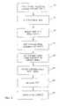
- FIG. 3is a flow diagram illustrating a preferred series of process steps for fabricating a feedthrough assembly in accordance with the present invention.
- FIGS. 4A-4Erespectively depict the fabrication stages of a feedthrough assembly in accordance with the process flow illustrated in FIG. 3 , wherein FIG. 4A depicts a plane view of a unfired ceramic sheet;
- FIG. 4 B 1shows patterns of blind holes in the sheet and FIG. 4 B 2 is a sectional view taken along plane 4 B 2 - 4 B 2 ;
- FIG. 4 C 1shows wires inserted into the blind holes and FIG. 4 C 2 is a sectional view taken along plane 4 C 2 - 4 C 2 ;
- FIG. 4 D 1shows the sheet and wires after being fired and FIG. 4 D 2 is a sectional view taken along plane 4 D 2 - 4 D 2 depicting the removal of material from the lower sheet surface to align the wire lower faces with the sheet lower surface;
- FIG. 4Eshows the sheet after dicing to form multiple feedthrough assemblies
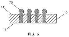
- FIG. 5comprises a sectional view similar to FIG. 2 but depicting an alternative embodiment of the invention.
- FIGS. 1 and 2depict a preferred feedthrough assembly 8 in accordance with the present invention comprising a thin sheet 10 of ceramic material having multiple electrical feedthroughs 12 extending therethrough terminating flush with the upper and lower surfaces 14 , 16 of sheet 10 .
- the sheet 10typically comprises a wall portion of a housing (not shown) for accommodating electronic circuitry.
- the feedthroughs 12function to electrically connect devices external to the housing, e.g., adjacent to surface 14 , to electronic circuitry contained within the housing, e.g., adjacent to surface 16 .
- Electrical feedthroughs in accordance with the inventionare intended to function in corrosive environments, e.g., in medical devices intended for implantation in a patient's body.
- the device housingbe hermetically sealed which, of course, requires that all feedthroughs in the housing wall also be hermetic.
- Biocompatibilityassures that the implanted device has no deleterious effect on body tissue.
- Electrochemical stabilityassures that the corrosive environment of the body has no deleterious effect on the device. Ceramic and platinum materials are often used in implantable medical devices because they typically exhibit both biocompatibility and electrochemical stability.
- the present inventionis directed to providing electrical feedthroughs compatible with thin ceramic sheets (or substrates) having a finished thickness of .ltoreq.40 mils, which feedthroughs are hermetic, biocompatible, and electrochemically stable.
- the ceramic sheet 10is formed of 99% aluminum oxide and the feedthrough wires 12 are solid and formed of high purity platinum having a diameter .ltoreq.20 mils.
- FIGS. 3 and 4 A- 4 Edepict the preferred processed steps for fabricating the finished feedthrough assembly 8 illustrated in FIGS. 1 and 2 .
- an unfired ceramic sheet 20( FIG. 4A ), preferably of .gtoreq.99% aluminum oxide is selected.
- the unfired ceramic sheetis preferably formed by rolling unfired ceramic material to impart shear forces to agglomerates in the moist ceramic slurry. This rolling process breaks down these agglomerates and produces a sheet of dense uniformly distributed fine aluminum oxide particulate.
- a pattern 24 of blind holes 26is drilled into the sheet 20 as represented by block 28 in FIG. 3 .
- the pattern 24is replicated at 24 A, 24 B, 24 C, 24 D.
- the unfired sheet 20has a thickness of 40 mils and that each hole 26 has a diameter of 4.3 mils (i.e., 0.0043′′) and is drilled from a sheet upper surface 32 toward a sheet lower surface 34 , terminating at a hole floor 36 FIG. 4B .
- the hole patternis densely being comprised of holes spaced by .ltoreq.40 mils from adjacent holes and in some applications by .ltoreq.20 mils.
- Step 37 of FIG. 3calls for cutting lengths of solid homogenous high purity platinum wire to form multiple wire pieces 38 , each having a length .gtoreq.20 mils.
- the wires 38are then inserted (step 39 , FIG. 3 ) into the blind holes 26 as depicted in FIG. 4 C 2 with the wire lower ends 40 resting on the hole floors 36 and the wire upper ends 41 extending above the sheet upper surface 32 . Since the holes 26 preferably have a diameter of 0.0043′′ and the wires 38 have a diameter of 0.0040′′, the wires can be readily, but snugly, received in the holes.
- Step 44 of FIG. 3calls for the ceramic/wire assembly to be fired.
- the maximum firing temperatureshould be sufficient to sinter the material of the ceramic sheet 20 but insufficient to melt the material of the wires 38 .
- a firing temperature of 1600.degree. C.satisfies this requirement.
- An exemplary preferred firing scheduleincludes ramping the assembly up to 600.degree. C. at a rate of 1.degree. C./minute, then ramping up to 1600.degree. C. at a rate at 5.degree. C./minute, followed by a one hour dwell and then a cool-to-room-temperature interval.
- the ceramicexpands shrinking the holes around the wires 38 to form a compression seal.
- the shrinkageis believed to occur, at least in part, as a consequence of polymer binder burnout.
- the fine aluminum oxide suspensionpermits uniform and continuous sealing around the surface of the wire.
- the maximum firing temperaturee.g., 1600.degree. C.
- the solid platinum wires being squeezed by the ceramicexhibit sufficient plasticity to enable the platinum to flow and fill any crevices. This action produces a hermetic metal/ceramic interface.
- the feedthrough assemblycomprised of the finished ceramic sheet and feedthrough wires, is subjected to a hermeticity test, e.g., frequently a helium leak test as represented by block 56 in FIG. 3 . Thereafter, the ceramic sheet 20 can be subjected to a singulation or dicing step 58 to provide multiple feedthrough assemblies 60 A, 60 B, 60 C, 60 D.
- FIG. 5shows an alternative embodiment of the invention in which the upper ends of the wires protrude beyond the ceramic sheet upper surface. More particularly, FIG. 5 is similar to FIG. 2 but shows the feedthroughs 12 A protruding above sheet upper surface 14 A and terminating at terminal 70 .
- Terminal 70can be essentially spherically shaped, as shown, or can be otherwise configured to facilitate interconnection with mating terminals (not shown), as by welding.
Landscapes
- Engineering & Computer Science (AREA)
- Manufacturing & Machinery (AREA)
- Microelectronics & Electronic Packaging (AREA)
- Computer Hardware Design (AREA)
- General Physics & Mathematics (AREA)
- Condensed Matter Physics & Semiconductors (AREA)
- Physics & Mathematics (AREA)
- Ceramic Engineering (AREA)
- Power Engineering (AREA)
- Ceramic Products (AREA)
- Materials For Medical Uses (AREA)
- Prostheses (AREA)
- Compositions Of Oxide Ceramics (AREA)
Abstract
Description
This application is a divisional application of U.S. patent application Ser. No. 11/493,469, filed Jul. 25, 2006, for Method and Apparatus for Providing Hermetic Electrical Feedthrough, published as 2006/0283624 now U.S. Pat. No. 7,989,080, which is a division of U.S. patent application Ser. No. 09/823,464, filed Mar. 30, 2001 for Method and Apparatus for Providing Hermetic Electrical Feedthrough, now U.S. Pat. No. 7,480,988, the disclosures of which is incorporated herein by reference.
This invention relates generally to a method and apparatus for providing electrical feedthroughs and more particularly to a method and apparatus suitable for forming hermetic electrical feedthroughs through a thin ceramic sheet. “Thin ceramic sheet” as used herein refers to a sheet having a finished thickness dimension of .ltoreq.40 mils, i.e., 1 mm. Apparatus in accordance with the invention is particularly suited for use in corrosive environments such as in medical devices implanted in a patient's body.
Various approaches are described in the literature for fabricating hermetically sealed electrical circuit housings suitable for extended operation in corrosive environments, e.g., in medical devices implanted in a patient's body. For such applications, housing must be formed of biocompatible and electrochemically stable materials and typically must include a wall containing multiple hermetic electrical feedthroughs. A hermetic electrical feedthrough is comprised of electrically conductive material which extends through and is hermetically sealed in the wall material.
One known approach for forming feedthroughs uses platinum thickfilm vias through 92% or 96% aluminum oxide ceramic with significant glass content. This glass content is susceptible to hydroxide etching that may occur as an electrochemical reaction to an aqueous chloride environment such as is found in the human body. This will, over extended time, compromise the hermeticity and structural stability of the feedthrough. Typically, 92% aluminum oxide ceramic is used in conjunction with a platinum/glass or platinum/aluminum oxide thickfilm paste. These material systems are generally formulated to optimize coefficient of thermal expansion mismatches and achieve a hermetic feedthrough. However, use of metal/insulator frit significantly reduces the conductive volume of the feedthrough limiting the current carrying capacity of the feedthrough.
An alternative approach uses an assembled pin feedthrough consisting of a conductive pin that is bonded chemically at its perimeter through brazing or the use of oxides, and/or welded, and/or mechanically bonded through compression to a ceramic body. Typically, gold is used as a braze material that wets the feedthrough pin and the ceramic body resulting in a hermetic seal. Wetting to the ceramic body requires a deposited layer of metal such as titanium. This layer acts additionally as a diffusion barrier for the gold.
Other alternative feedthrough approaches use a metal tube cofired with a green ceramic sheet. The hermeticity of the metal/ceramic interface is achieved by a compression seal formed by material shrinkage when the assembly is fired and then allowed to cool. The use of a tube inherently limits the smallest possible feedthrough to the smallest available tubing. Acceptable results have been reported only when using tubes having a diameter>40 mils in ceramic substrates at least 70 mils thick.
The present invention is directed to a method and apparatus suitable for forming hermetic electrical feedthroughs in a ceramic sheet (or substrate) having a thickness of .ltoreq.40 mils. More particularly, the invention is directed to a method and apparatus for forming a structure including a hermetic electrical feedthrough which is both biocompatible and electrochemically stable and suitable for implantation in a patient's body.
A preferred method in accordance with the invention involves:
(a) providing a green, or unfired, ceramic sheet having a thickness of .ltoreq.40 mils and preferably comprising .ltoreq.99% aluminum oxide;
(b) forming multiple blind holes in said sheet extending from a sheet upper surface toward a sheet lower surface;
(c) inserting solid wires (or pins), preferably of platinum, in said holes, the wires and holes preferably having a diameter of .ltoreq.20 mils;
(d) firing the assembly of sheet and wires to a temperature (e.g., 1600.degree. C.) sufficient to sinter the sheet material but insufficient to melt the wires, to cause ceramic shrinkage to form hermetic compression seals around the wires; (e) removing, e.g., as by grinding or lapping, sufficient material from the sheet lower surface so that the lower ends of said wires are flush with the finished sheet lower surface.
Preferred embodiments of the invention employ an unfired ceramic sheet of .ltoreq.99% aluminum oxide but alternative embodiments can use other ceramic materials, e.g., zirconia. The wires preferably comprise high purity platinum. However, because the firing temperature of the ceramic can be tailored within certain limits, various other metals, e.g., titanium, gold, palladium, tantalum and niobium, can be used for the feedthrough material, i.e., wires.
In one preferred method of practicing the invention, a 40 mil thick sheet of .gtoreq.99% aluminum oxide is drilled to form one or more blind holes, each having a diameter slightly greater than 4 mils and a depth of about 20 mils. A 4 mil diameter platinum wire cut to a length greater than 20 mils is then inserted into each hole. The ceramic sheet/wire assembly is then fired to a temperature sufficient to sinter the ceramic but insufficient to melt the platinum. An exemplary firing schedule includes ramping up to 600.degree. C. at a rate of 1.degree. C./minute, then ramping up to 1600.degree. C. at a rate of 5.degree. C./minute, followed by a one hour dwell and then a cool-to-room-temperature interval. The heating and subsequent cooling of the ceramic material causes the holes to shrink and the ceramic to form a compression seal against the wires. The ceramic sheet is then lapped from the lower sheet surface until the wires are visible. In a preferred embodiment, both surfaces of the ceramic sheet are then polished so that the wires terminate flush with both sheet surfaces leaving the surfaces ready for subsequent processing, e.g., lithography, chip/component surface mounting etc. The sheet/wire assembly is then preferably finished to a thickness .ltoreq.20 mils, e.g., less than 12 mils.
Embodiments constructed in accordance with the present invention are able to achieve very high feedthrough density. For example only, in applications where miniaturization is important, the feedthrough pitch, i.e., center-to-center distance between adjacent feedthroughs is .ltoreq.40 mils, and preferably .ltoreq.20 mils.
FIG.4B1 shows patterns of blind holes in the sheet and FIG.4B2 is a sectional view taken along plane4B2-4B2;
FIG.4C1 shows wires inserted into the blind holes and FIG.4C2 is a sectional view taken along plane4C2-4C2;
FIG.4D1 shows the sheet and wires after being fired and FIG.4D2 is a sectional view taken along plane4D2-4D2 depicting the removal of material from the lower sheet surface to align the wire lower faces with the sheet lower surface;
Attention is initially directed toFIGS. 1 and 2 which depict apreferred feedthrough assembly 8 in accordance with the present invention comprising athin sheet 10 of ceramic material having multipleelectrical feedthroughs 12 extending therethrough terminating flush with the upper andlower surfaces sheet 10. Thesheet 10 typically comprises a wall portion of a housing (not shown) for accommodating electronic circuitry. Thefeedthroughs 12 function to electrically connect devices external to the housing, e.g., adjacent to surface14, to electronic circuitry contained within the housing, e.g., adjacent to surface16.
Electrical feedthroughs in accordance with the invention are intended to function in corrosive environments, e.g., in medical devices intended for implantation in a patient's body. In such applications, it is generally critical that the device housing be hermetically sealed which, of course, requires that all feedthroughs in the housing wall also be hermetic. In such applications, it is also generally desirable that the weight and size of the housing be minimized and that all exposed areas of the housing be biocompatible and electrochemically stable. Biocompatibility assures that the implanted device has no deleterious effect on body tissue. Electrochemical stability assures that the corrosive environment of the body has no deleterious effect on the device. Ceramic and platinum materials are often used in implantable medical devices because they typically exhibit both biocompatibility and electrochemical stability.
The present invention is directed to providing electrical feedthroughs compatible with thin ceramic sheets (or substrates) having a finished thickness of .ltoreq.40 mils, which feedthroughs are hermetic, biocompatible, and electrochemically stable. In accordance with a preferred embodiment of the invention, theceramic sheet 10 is formed of 99% aluminum oxide and thefeedthrough wires 12 are solid and formed of high purity platinum having a diameter .ltoreq.20 mils.
Attention is now directed to FIGS.3 and4A-4E which depict the preferred processed steps for fabricating thefinished feedthrough assembly 8 illustrated inFIGS. 1 and 2 .
Initially, an unfired ceramic sheet20 (FIG. 4A ), preferably of .gtoreq.99% aluminum oxide is selected. The unfired ceramic sheet is preferably formed by rolling unfired ceramic material to impart shear forces to agglomerates in the moist ceramic slurry. This rolling process breaks down these agglomerates and produces a sheet of dense uniformly distributed fine aluminum oxide particulate.
Apattern 24 ofblind holes 26 is drilled into thesheet 20 as represented byblock 28 inFIG. 3 . Note that thepattern 24 is replicated at24A,24B,24C,24D. In an exemplary preferred embodiment, it will be assumed that theunfired sheet 20 has a thickness of 40 mils and that eachhole 26 has a diameter of 4.3 mils (i.e., 0.0043″) and is drilled from a sheetupper surface 32 toward a sheetlower surface 34, terminating at ahole floor 36FIG. 4B . In typical applications, the hole pattern is densely being comprised of holes spaced by .ltoreq.40 mils from adjacent holes and in some applications by .ltoreq.20 mils.
During the firing and subsequent cooling, the ceramic expands shrinking the holes around thewires 38 to form a compression seal. The shrinkage is believed to occur, at least in part, as a consequence of polymer binder burnout. The fine aluminum oxide suspension permits uniform and continuous sealing around the surface of the wire. Additionally, at the maximum firing temperature, e.g., 1600.degree. C., the solid platinum wires being squeezed by the ceramic exhibit sufficient plasticity to enable the platinum to flow and fill any crevices. This action produces a hermetic metal/ceramic interface.
After lapping, the feedthrough assembly comprised of the finished ceramic sheet and feedthrough wires, is subjected to a hermeticity test, e.g., frequently a helium leak test as represented byblock 56 inFIG. 3 . Thereafter, theceramic sheet 20 can be subjected to a singulation or dicingstep 58 to providemultiple feedthrough assemblies
Attention is now directed toFIG. 5 which shows an alternative embodiment of the invention in which the upper ends of the wires protrude beyond the ceramic sheet upper surface. More particularly,FIG. 5 is similar toFIG. 2 but shows the feedthroughs12A protruding above sheet upper surface14A and terminating atterminal 70.Terminal 70 can be essentially spherically shaped, as shown, or can be otherwise configured to facilitate interconnection with mating terminals (not shown), as by welding.
From the foregoing, it should now be appreciated that electrical feedthrough assemblies and fabrication methods therefore have been described suitable for use in medical devices intended for implantation in a patient's body. Although a specific structure and fabrication method has been described, it is recognized that variations and modifications will occur to those skilled in the art coming within the spirit and scope of the invention as defined by the appended claims.
Claims (15)
1. A hermetic structure comprising: a sheet of ceramic material having upper and lower parallel surfaces spaced by less than 40 mils; at least one feedthrough filled with electrically conductive material formed of substantially pure platinum, extending through said sheet, in contact with said sheet; and wherein said sheet of ceramic material forms a hermetic seal around said electrically conductive material.
2. The hermetic structure according toclaim 1 , wherein said upper and lower surfaces are spaced by less than 20 mils.
3. The hermetic structure according toclaim 1 , including a plurality of feedthroughs filled with electrically conductive material extending through said sheet; and wherein at least some of said feedthroughs are spaced by less than 20 mils.
4. The hermetic structure according toclaim 1 , wherein said electrically conductive material includes an end terminating flush with one of said sheet surfaces.
5. The hermetic structure according toclaim 1 , wherein one end of said electrically conductive material protrudes beyond one of said sheet surfaces.
6. The hermetic structure according toclaim 1 , wherein said feedthrough has a diameter of less than 10 mils.
7. The hermetic structure according toclaim 1 , wherein said ceramic material is from the group comprised of aluminum oxide and zirconia.
8. The hermetic structure according toclaim 1 , wherein said ceramic material comprises at least 99% aluminum oxide.
9. A hermetic structure comprising: a sheet of ceramic material having upper and lower parallel surfaces spaced by less than about 40 mils; at least one feedthrough filled with electrically conductive material formed of substantially pure platinum, extending through said sheet, in contact with said sheet; said sheet of ceramic material forming a hermetic seal around said electrically conductive material; and wherein said feedthrough has a diameter of less than 10 mils.
10. The hermetic structure according toclaim 9 , wherein said upper and lower surfaces are spaced by less than 20 mils.
11. The hermetic structure according toclaim 9 , including a plurality of feedthroughs filled with electrically conductive material extending through said sheet; and wherein at least some of said electrically conductive materials are spaced by less than 20 mils.
12. The hermetic structure according toclaim 9 , wherein said electrically conductive material includes an end terminating flush with one of said sheet surfaces.
13. The hermetic structure according toclaim 9 , wherein one end of said electrically conductive material protrudes beyond one of said sheet surfaces.
14. The hermetic structure according toclaim 9 , wherein said ceramic material comprises aluminum oxide, zirconia, or mixtures thereof.
15. The hermetic structure according toclaim 9 , wherein said ceramic material comprises at least 99% aluminum oxide.
Priority Applications (1)
| Application Number | Priority Date | Filing Date | Title |
|---|---|---|---|
| US13/165,388US8163397B2 (en) | 2001-03-30 | 2011-06-21 | Method and apparatus for providing hermetic electrical feedthrough |
Applications Claiming Priority (3)
| Application Number | Priority Date | Filing Date | Title |
|---|---|---|---|
| US09/823,464US7480988B2 (en) | 2001-03-30 | 2001-03-30 | Method and apparatus for providing hermetic electrical feedthrough |
| US11/493,469US7989080B2 (en) | 2001-03-30 | 2006-07-25 | Method and apparatus for providing hermetic electrical feedthrough |
| US13/165,388US8163397B2 (en) | 2001-03-30 | 2011-06-21 | Method and apparatus for providing hermetic electrical feedthrough |
Related Parent Applications (1)
| Application Number | Title | Priority Date | Filing Date |
|---|---|---|---|
| US11/493,469DivisionUS7989080B2 (en) | 2001-03-30 | 2006-07-25 | Method and apparatus for providing hermetic electrical feedthrough |
Publications (2)
| Publication Number | Publication Date |
|---|---|
| US20110253432A1 US20110253432A1 (en) | 2011-10-20 |
| US8163397B2true US8163397B2 (en) | 2012-04-24 |
Family
ID=25238834
Family Applications (3)
| Application Number | Title | Priority Date | Filing Date |
|---|---|---|---|
| US09/823,464Expired - Fee RelatedUS7480988B2 (en) | 2001-03-30 | 2001-03-30 | Method and apparatus for providing hermetic electrical feedthrough |
| US11/493,469Expired - Fee RelatedUS7989080B2 (en) | 2001-03-30 | 2006-07-25 | Method and apparatus for providing hermetic electrical feedthrough |
| US13/165,388Expired - Fee RelatedUS8163397B2 (en) | 2001-03-30 | 2011-06-21 | Method and apparatus for providing hermetic electrical feedthrough |
Family Applications Before (2)
| Application Number | Title | Priority Date | Filing Date |
|---|---|---|---|
| US09/823,464Expired - Fee RelatedUS7480988B2 (en) | 2001-03-30 | 2001-03-30 | Method and apparatus for providing hermetic electrical feedthrough |
| US11/493,469Expired - Fee RelatedUS7989080B2 (en) | 2001-03-30 | 2006-07-25 | Method and apparatus for providing hermetic electrical feedthrough |
Country Status (3)
| Country | Link |
|---|---|
| US (3) | US7480988B2 (en) |
| AU (1) | AU2002254319A1 (en) |
| WO (1) | WO2002078781A2 (en) |
Cited By (47)
| Publication number | Priority date | Publication date | Assignee | Title |
|---|---|---|---|---|
| US20110034966A1 (en)* | 2009-08-04 | 2011-02-10 | W. C. Heraeus Gmbh | Electrical bushing for an implantable medical device |
| US20110034965A1 (en)* | 2009-08-04 | 2011-02-10 | W. C. Heraeus Gmbh | Cermet-containing bushing for an implantable medical device |
| US20110186349A1 (en)* | 2010-02-02 | 2011-08-04 | W. C. Heraeus Gmbh | Electrical bushing with gradient cermet |
| US20110190885A1 (en)* | 2010-02-02 | 2011-08-04 | W. C. Heraeus Gmbh | Method for sintering electrical bushings |
| US20120006060A1 (en)* | 2010-07-08 | 2012-01-12 | Eiji Terao | Method of manufacturing glass substrate and method of manufacturing electronic components |
| US20120006061A1 (en)* | 2010-07-08 | 2012-01-12 | Eiji Terao | Method of manufacturing glass substrate and method of manufacturing electronic components |
| US20120203294A1 (en)* | 2011-01-31 | 2012-08-09 | Heraeus Precious Metals Gmbh & Co. Kg | Ceramic bushing having high conductivity conducting elements |
| US20120200011A1 (en)* | 2011-01-31 | 2012-08-09 | Heraeus Precious Metals Gmbh & Co. Kg | Method for the manufacture of a cermet-containing bushing |
| US8322027B1 (en)* | 2005-10-26 | 2012-12-04 | Second Sight Medical Products, Inc. | Flexible circuit electrode array and method of manufacturing the same |
| EP2617461A1 (en) | 2012-01-16 | 2013-07-24 | Greatbatch Ltd. | Co-fired hermetically sealed feedthrough with alumina substrate and platinum filled via for an active implantable medical device |
| US9032614B2 (en) | 2011-01-31 | 2015-05-19 | Heraeus Precious Metals Gmbh & Co. Kg | Method for manufacturing an electrical bushing for an implantable medical device |
| US9040819B2 (en) | 2011-01-31 | 2015-05-26 | Heraeus Precious Metals Gmbh & Co. Kg | Implantable device having an integrated ceramic bushing |
| US9048608B2 (en) | 2011-01-31 | 2015-06-02 | Heraeus Precious Metals Gmbh & Co. Kg | Method for the manufacture of a cermet-containing bushing for an implantable medical device |
| US9088093B2 (en) | 2011-01-31 | 2015-07-21 | Heraeus Precious Metals Gmbh & Co. Kg | Head part for an implantable medical device |
| US9108066B2 (en) | 2008-03-20 | 2015-08-18 | Greatbatch Ltd. | Low impedance oxide resistant grounded capacitor for an AIMD |
| US9126053B2 (en) | 2011-01-31 | 2015-09-08 | Heraeus Precious Metals Gmbh & Co. Kg | Electrical bushing with cermet-containing connecting element for an active implantable medical device |
| US9306318B2 (en) | 2011-01-31 | 2016-04-05 | Heraeus Deutschland GmbH & Co. KG | Ceramic bushing with filter |
| US9403023B2 (en) | 2013-08-07 | 2016-08-02 | Heraeus Deutschland GmbH & Co. KG | Method of forming feedthrough with integrated brazeless ferrule |
| US9427596B2 (en) | 2013-01-16 | 2016-08-30 | Greatbatch Ltd. | Low impedance oxide resistant grounded capacitor for an AIMD |
| US9431801B2 (en) | 2013-05-24 | 2016-08-30 | Heraeus Deutschland GmbH & Co. KG | Method of coupling a feedthrough assembly for an implantable medical device |
| US9478959B2 (en) | 2013-03-14 | 2016-10-25 | Heraeus Deutschland GmbH & Co. KG | Laser welding a feedthrough |
| US9504841B2 (en) | 2013-12-12 | 2016-11-29 | Heraeus Deutschland GmbH & Co. KG | Direct integration of feedthrough to implantable medical device housing with ultrasonic welding |
| US9504840B2 (en) | 2011-01-31 | 2016-11-29 | Heraeus Deutschland GmbH & Co. KG | Method of forming a cermet-containing bushing for an implantable medical device having a connecting layer |
| US9509272B2 (en) | 2011-01-31 | 2016-11-29 | Heraeus Deutschland GmbH & Co. KG | Ceramic bushing with filter |
| US9552899B2 (en) | 2011-01-31 | 2017-01-24 | Heraeus Deutschland GmbH & Co. KG | Ceramic bushing for an implantable medical device |
| US9610452B2 (en) | 2013-12-12 | 2017-04-04 | Heraeus Deutschland GmbH & Co. KG | Direct integration of feedthrough to implantable medical device housing by sintering |
| US9610451B2 (en) | 2013-12-12 | 2017-04-04 | Heraeus Deutschland GmbH & Co. KG | Direct integration of feedthrough to implantable medical device housing using a gold alloy |
| USRE46699E1 (en) | 2013-01-16 | 2018-02-06 | Greatbatch Ltd. | Low impedance oxide resistant grounded capacitor for an AIMD |
| US9889306B2 (en) | 2012-01-16 | 2018-02-13 | Greatbatch Ltd. | Hermetically sealed feedthrough with co-fired filled via and conductive insert for an active implantable medical device |
| US9931514B2 (en) | 2013-06-30 | 2018-04-03 | Greatbatch Ltd. | Low impedance oxide resistant grounded capacitor for an AIMD |
| US10046166B2 (en) | 2012-01-16 | 2018-08-14 | Greatbatch Ltd. | EMI filtered co-connected hermetic feedthrough, feedthrough capacitor and leadwire assembly for an active implantable medical device |
| US10080889B2 (en) | 2009-03-19 | 2018-09-25 | Greatbatch Ltd. | Low inductance and low resistance hermetically sealed filtered feedthrough for an AIMD |
| US10092766B2 (en) | 2011-11-23 | 2018-10-09 | Heraeus Deutschland GmbH & Co. KG | Capacitor and method to manufacture the capacitor |
| EP3449973A1 (en) | 2017-08-30 | 2019-03-06 | Greatbatch Ltd. | Hermetically sealed filtered feedthrough assembly |
| US10249415B2 (en) | 2017-01-06 | 2019-04-02 | Greatbatch Ltd. | Process for manufacturing a leadless feedthrough for an active implantable medical device |
| WO2019129893A2 (en) | 2018-06-19 | 2019-07-04 | Morgan Advanced Ceramics, Inc | Feedthroughs |
| US10350421B2 (en) | 2013-06-30 | 2019-07-16 | Greatbatch Ltd. | Metallurgically bonded gold pocket pad for grounding an EMI filter to a hermetic terminal for an active implantable medical device |
| US10420949B2 (en) | 2012-01-16 | 2019-09-24 | Greatbatch Ltd. | Method of manufacturing a feedthrough insulator for an active implantable medical device incorporating a post conductive paste filled pressing step |
| US10561837B2 (en) | 2011-03-01 | 2020-02-18 | Greatbatch Ltd. | Low equivalent series resistance RF filter for an active implantable medical device utilizing a ceramic reinforced metal composite filled via |
| US10589107B2 (en) | 2016-11-08 | 2020-03-17 | Greatbatch Ltd. | Circuit board mounted filtered feedthrough assembly having a composite conductive lead for an AIMD |
| US10881867B2 (en) | 2012-01-16 | 2021-01-05 | Greatbatch Ltd. | Method for providing a hermetically sealed feedthrough with co-fired filled via for an active implantable medical device |
| US10905888B2 (en) | 2018-03-22 | 2021-02-02 | Greatbatch Ltd. | Electrical connection for an AIMD EMI filter utilizing an anisotropic conductive layer |
| US10912945B2 (en) | 2018-03-22 | 2021-02-09 | Greatbatch Ltd. | Hermetic terminal for an active implantable medical device having a feedthrough capacitor partially overhanging a ferrule for high effective capacitance area |
| US11198014B2 (en) | 2011-03-01 | 2021-12-14 | Greatbatch Ltd. | Hermetically sealed filtered feedthrough assembly having a capacitor with an oxide resistant electrical connection to an active implantable medical device housing |
| EP4147746A1 (en) | 2021-09-10 | 2023-03-15 | Greatbatch Ltd. | A ceramic reinforced metal composite for hermetic bodies for implantable devices |
| US11701519B2 (en) | 2020-02-21 | 2023-07-18 | Heraeus Medical Components Llc | Ferrule with strain relief spacer for implantable medical device |
| US11894163B2 (en) | 2020-02-21 | 2024-02-06 | Heraeus Medical Components Llc | Ferrule for non-planar medical device housing |
Families Citing this family (53)
| Publication number | Priority date | Publication date | Assignee | Title |
|---|---|---|---|---|
| US7480988B2 (en)* | 2001-03-30 | 2009-01-27 | Second Sight Medical Products, Inc. | Method and apparatus for providing hermetic electrical feedthrough |
| WO2003061537A1 (en)* | 2002-01-17 | 2003-07-31 | Masachusetts Eye And Ear Infirmary | Minimally invasive retinal prosthesis |
| AU2003901146A0 (en)* | 2003-03-12 | 2003-03-27 | Cochlear Limited | Feedthrough assembly |
| US7263403B2 (en)* | 2004-05-25 | 2007-08-28 | Second Sight Medical Products, Inc. | Retinal prosthesis |
| JP4958898B2 (en)* | 2005-04-28 | 2012-06-20 | セカンド サイト メディカル プロダクツ インコーポレイテッド | Implantable neurostimulator package |
| US8763245B1 (en)* | 2006-06-30 | 2014-07-01 | Glysens, Inc., a California Corporation | Hermetic feedthrough assembly for ceramic body |
| AU2007284422B2 (en) | 2006-08-18 | 2011-06-02 | Second Sight Medical Products, Inc. | Package for an implantable neural stimulation device |
| DE102006041939A1 (en)* | 2006-09-07 | 2008-03-27 | Biotronik Crm Patent Ag | Electrical implementation |
| AU2007355605B2 (en)* | 2007-06-25 | 2012-04-26 | Second Sight Medical Products, Inc. | Method for providing hermetic electrical feedthrough |
| JP4856025B2 (en)* | 2007-08-10 | 2012-01-18 | セイコーインスツル株式会社 | Airtight terminal manufacturing method and airtight terminal, piezoelectric vibrator manufacturing method and piezoelectric vibrator, oscillator, electronic device, radio timepiece |
| WO2009086435A2 (en)* | 2007-12-28 | 2009-07-09 | Emerson Electric Co. | Hermetic feed-through with hybrid seal structure |
| US10390441B1 (en)* | 2008-05-28 | 2019-08-20 | Second Sight Medical Products, Inc. | Method for providing hermetic electrical feedthrough |
| US8706243B2 (en) | 2009-02-09 | 2014-04-22 | Rainbow Medical Ltd. | Retinal prosthesis techniques |
| US8718784B2 (en)* | 2010-01-14 | 2014-05-06 | Nano-Retina, Inc. | Penetrating electrodes for retinal stimulation |
| US8150526B2 (en) | 2009-02-09 | 2012-04-03 | Nano-Retina, Inc. | Retinal prosthesis |
| US8442641B2 (en) | 2010-08-06 | 2013-05-14 | Nano-Retina, Inc. | Retinal prosthesis techniques |
| US8428740B2 (en) | 2010-08-06 | 2013-04-23 | Nano-Retina, Inc. | Retinal prosthesis techniques |
| US8698006B2 (en)* | 2009-06-04 | 2014-04-15 | Morgan Advanced Ceramics, Inc. | Co-fired metal and ceramic composite feedthrough assemblies for use at least in implantable medical devices and methods for making the same |
| US20110139484A1 (en)* | 2009-12-15 | 2011-06-16 | Advanced Bionics, Llc | Hermetic Electrical Feedthrough |
| US8476538B2 (en)* | 2010-03-08 | 2013-07-02 | Formfactor, Inc. | Wiring substrate with customization layers |
| WO2011137298A2 (en) | 2010-04-30 | 2011-11-03 | Second Sight Medical Products,Inc. | Improved biocompatible bonding method |
| US9174047B2 (en)* | 2010-05-12 | 2015-11-03 | Advanced Bionics Ag | Electrical feedthrough assembly |
| US9643021B2 (en) | 2013-01-08 | 2017-05-09 | Advanced Bionics Ag | Electrical feedthrough assembly |
| US8552311B2 (en) | 2010-07-15 | 2013-10-08 | Advanced Bionics | Electrical feedthrough assembly |
| US8386047B2 (en) | 2010-07-15 | 2013-02-26 | Advanced Bionics | Implantable hermetic feedthrough |
| JP5738553B2 (en)* | 2010-07-29 | 2015-06-24 | 京セラ株式会社 | Living body embedded member and method for manufacturing living body embedded member |
| US8571669B2 (en) | 2011-02-24 | 2013-10-29 | Nano-Retina, Inc. | Retinal prosthesis with efficient processing circuits |
| KR20140082642A (en) | 2011-07-26 | 2014-07-02 | 글리젠스 인코포레이티드 | Tissue implantable sensor with hermetically sealed housing |
| US9008779B2 (en) | 2011-08-02 | 2015-04-14 | Medtronic, Inc. | Insulator for a feedthrough |
| US8841558B2 (en) | 2011-08-02 | 2014-09-23 | Medtronic Inc. | Hermetic feedthrough |
| US9724524B2 (en) | 2011-08-02 | 2017-08-08 | Medtronic, Inc. | Interconnection of conductor to feedthrough |
| US8588916B2 (en) | 2011-08-02 | 2013-11-19 | Medtronic, Inc. | Feedthrough configured for interconnect |
| US8872035B2 (en) | 2011-08-02 | 2014-10-28 | Medtronic, Inc. | Hermetic feedthrough |
| US8670829B2 (en) | 2011-08-02 | 2014-03-11 | Medtronic, Inc. | Insulator for a feedthrough |
| US9627833B2 (en) | 2011-08-02 | 2017-04-18 | Medtronic, Inc. | Electrical leads for a feedthrough |
| DE102012207580A1 (en)* | 2012-05-08 | 2013-11-14 | Olympus Winter & Ibe Gmbh | Surgical instrument with through-hole |
| DE102012209620B4 (en) | 2012-06-08 | 2023-01-19 | Robert Bosch Gmbh | Method for manufacturing a sensor carrier, sensor carrier and sensor |
| US10561353B2 (en) | 2016-06-01 | 2020-02-18 | Glysens Incorporated | Biocompatible implantable sensor apparatus and methods |
| US10660550B2 (en) | 2015-12-29 | 2020-05-26 | Glysens Incorporated | Implantable sensor apparatus and methods |
| US20150250386A1 (en)* | 2012-09-28 | 2015-09-10 | Csem Centre Suisse D'electronique Et De Microtechnique Sa -Recherche Et Developpement | Implantable devices |
| US9370417B2 (en) | 2013-03-14 | 2016-06-21 | Nano-Retina, Inc. | Foveated retinal prosthesis |
| US9583458B2 (en) | 2013-03-15 | 2017-02-28 | The Charles Stark Draper Laboratory, Inc. | Methods for bonding a hermetic module to an electrode array |
| US9892816B2 (en)* | 2013-06-27 | 2018-02-13 | Heraeus Precious Metals North America Conshohocken Llc | Platinum containing conductive paste |
| FR3012965B1 (en) | 2013-11-14 | 2016-01-08 | Commissariat Energie Atomique | DEVICE FOR CROSSING IN PARTICULAR FOR A MEDICAL IMPLANT SYSTEM AND METHOD FOR MAKING THE SAME. |
| US9474902B2 (en) | 2013-12-31 | 2016-10-25 | Nano Retina Ltd. | Wearable apparatus for delivery of power to a retinal prosthesis |
| US9331791B2 (en) | 2014-01-21 | 2016-05-03 | Nano Retina Ltd. | Transfer of power and data |
| US10638962B2 (en) | 2016-06-29 | 2020-05-05 | Glysens Incorporated | Bio-adaptable implantable sensor apparatus and methods |
| EP3381510A1 (en) | 2017-03-27 | 2018-10-03 | Greatbatch Ltd. | Feedthrough assembly and flexible substrate assembly therefor |
| US10638979B2 (en) | 2017-07-10 | 2020-05-05 | Glysens Incorporated | Analyte sensor data evaluation and error reduction apparatus and methods |
| US11278668B2 (en) | 2017-12-22 | 2022-03-22 | Glysens Incorporated | Analyte sensor and medicant delivery data evaluation and error reduction apparatus and methods |
| US11255839B2 (en) | 2018-01-04 | 2022-02-22 | Glysens Incorporated | Apparatus and methods for analyte sensor mismatch correction |
| DE102018204350A1 (en)* | 2018-03-21 | 2019-09-26 | Siemens Aktiengesellschaft | Arrangement for carrying out a plurality of electrical connections through a wall of an electrical transformer |
| WO2022217146A1 (en) | 2021-04-09 | 2022-10-13 | Samtec, Inc. | High aspect ratio vias filled with liquid metal fill |
Citations (21)
| Publication number | Priority date | Publication date | Assignee | Title |
|---|---|---|---|---|
| US3517437A (en) | 1967-06-19 | 1970-06-30 | Beckman Instruments Inc | Method of forming a terminal structure in a refractory base |
| US3999004A (en) | 1974-09-27 | 1976-12-21 | International Business Machines Corporation | Multilayer ceramic substrate structure |
| US5046242A (en) | 1982-07-27 | 1991-09-10 | Commonwealth Of Australia | Method of making feedthrough assemblies having hermetic seals between electrical feedthrough elements and ceramic carriers therefor |
| US5095246A (en) | 1989-10-23 | 1992-03-10 | Gte Laboratories Incorporated | Niobium-ceramic feedthrough assembly |
| US5109844A (en) | 1990-10-11 | 1992-05-05 | Duke University | Retinal microstimulation |
| US5241216A (en) | 1989-12-21 | 1993-08-31 | General Electric Company | Ceramic-to-conducting-lead hermetic seal |
| US5272283A (en) | 1982-07-27 | 1993-12-21 | Commonwealth Of Australia | Feedthrough assembly for cochlear prosthetic package |
| US5368220A (en) | 1992-08-04 | 1994-11-29 | Morgan Crucible Company Plc | Sealed conductive active alloy feedthroughs |
| US5515604A (en)* | 1992-10-07 | 1996-05-14 | Fujitsu Limited | Methods for making high-density/long-via laminated connectors |
| US5640764A (en) | 1995-05-22 | 1997-06-24 | Alfred E. Mann Foundation For Scientific Research | Method of forming a tubular feed-through hermetic seal for an implantable medical device |
| US5738270A (en) | 1994-10-07 | 1998-04-14 | Advanced Bionics Corporation | Brazeless ceramic-to-metal bonding for use in implantable devices |
| US5817984A (en) | 1995-07-28 | 1998-10-06 | Medtronic Inc | Implantable medical device wtih multi-pin feedthrough |
| US5935155A (en) | 1998-03-13 | 1999-08-10 | John Hopkins University, School Of Medicine | Visual prosthesis and method of using same |
| US5997999A (en)* | 1994-07-01 | 1999-12-07 | Shinko Electric Industries Co., Ltd. | Sintered body for manufacturing ceramic substrate |
| US6093476A (en)* | 1997-05-02 | 2000-07-25 | Shinko Electric Industries Co., Ltd. | Wiring substrate having vias |
| US6174175B1 (en)* | 1999-04-29 | 2001-01-16 | International Business Machines Corporation | High density Z-axis connector |
| US6329631B1 (en)* | 1999-09-07 | 2001-12-11 | Ray Yueh | Solder strip exclusively for semiconductor packaging |
| US6400989B1 (en) | 1997-02-21 | 2002-06-04 | Intelligent Implants Gmbh | Adaptive sensory-motor encoder for visual or acoustic prosthesis |
| US6458157B1 (en) | 1997-08-04 | 2002-10-01 | Suaning Gregg Joergen | Retinal stimulator |
| US7709961B2 (en)* | 2005-11-02 | 2010-05-04 | Second Sight Medical Products, Inc. | Implantable microelectronic device and method of manufacture |
| US7989080B2 (en)* | 2001-03-30 | 2011-08-02 | Second Sight Medical Products, Inc. | Method and apparatus for providing hermetic electrical feedthrough |
Family Cites Families (19)
| Publication number | Priority date | Publication date | Assignee | Title |
|---|---|---|---|---|
| GB962558A (en)* | 1960-10-12 | 1964-07-01 | Standard Telephones Cables Ltd | Improvements in or relating to the bonding of metals to ceramic materials |
| US3378802A (en)* | 1965-06-25 | 1968-04-16 | Beckman Instruments Inc | Variable resistance device |
| US3436109A (en)* | 1965-12-15 | 1969-04-01 | Corning Glass Works | Stressed hermetic seal and method of making said seal |
| FR2217290B1 (en)* | 1972-12-01 | 1975-03-28 | Quartex Sa | |
| US3929426A (en)* | 1974-05-08 | 1975-12-30 | Rca Corp | Method of anchoring metallic coated leads to ceramic bodies and lead-ceramic bodies formed thereby |
| US4690714A (en)* | 1979-01-29 | 1987-09-01 | Li Chou H | Method of making active solid state devices |
| EP0080535B1 (en)* | 1981-11-27 | 1985-08-28 | Krohne AG | Measuring head for an electro-magnetic flow meter |
| CA1260868A (en)* | 1984-04-11 | 1989-09-26 | Izaak Lindhout | Process for calcining green coke |
| JPS61163152A (en)* | 1985-01-14 | 1986-07-23 | 宇部興産株式会社 | Manufacture of artificial lightweight aggregate |
| US5464699A (en)* | 1988-04-18 | 1995-11-07 | Alloy Surfaces Co. Inc. | Pyrophoric materials and methods for making the same |
| DE59002238D1 (en)* | 1989-03-15 | 1993-09-16 | Asea Brown Boveri | METHOD FOR PRODUCING A CRYSTAL-ORIENTED SURFACE LAYER FROM A CERAMIC HIGH-TEMPERATURE SUPER LADDER. |
| US5229549A (en)* | 1989-11-13 | 1993-07-20 | Sumitomo Electric Industries, Ltd. | Ceramic circuit board and a method of manufacturing the ceramic circuit board |
| EP0432418B1 (en)* | 1989-11-16 | 1995-02-01 | Taiyo Yuden Co., Ltd. | Solid dielectric capacitor and method of manufacture |
| US5095759A (en)* | 1990-06-01 | 1992-03-17 | Gte Products Corporation | Platinum electrode bonded to ceramic |
| US5766670A (en)* | 1993-11-17 | 1998-06-16 | Ibm | Via fill compositions for direct attach of devices and methods for applying same |
| US6156978A (en)* | 1994-07-20 | 2000-12-05 | Raytheon Company | Electrical feedthrough and its preparation |
| DE19651851C1 (en)* | 1996-12-13 | 1998-08-27 | Degussa | Platinum-coated oxide ceramic object production |
| US6156130A (en)* | 1998-09-22 | 2000-12-05 | Endress Hauser Gmbh Co | Screen-printable or dispensable active brazing pastes and process for producing the same |
| US6413582B1 (en)* | 1999-06-30 | 2002-07-02 | General Electric Company | Method for forming metallic-based coating |
- 2001
- 2001-03-30USUS09/823,464patent/US7480988B2/ennot_activeExpired - Fee Related
- 2002
- 2002-03-22AUAU2002254319Apatent/AU2002254319A1/ennot_activeAbandoned
- 2002-03-22WOPCT/US2002/008742patent/WO2002078781A2/ennot_activeApplication Discontinuation
- 2006
- 2006-07-25USUS11/493,469patent/US7989080B2/ennot_activeExpired - Fee Related
- 2011
- 2011-06-21USUS13/165,388patent/US8163397B2/ennot_activeExpired - Fee Related
Patent Citations (21)
| Publication number | Priority date | Publication date | Assignee | Title |
|---|---|---|---|---|
| US3517437A (en) | 1967-06-19 | 1970-06-30 | Beckman Instruments Inc | Method of forming a terminal structure in a refractory base |
| US3999004A (en) | 1974-09-27 | 1976-12-21 | International Business Machines Corporation | Multilayer ceramic substrate structure |
| US5046242A (en) | 1982-07-27 | 1991-09-10 | Commonwealth Of Australia | Method of making feedthrough assemblies having hermetic seals between electrical feedthrough elements and ceramic carriers therefor |
| US5272283A (en) | 1982-07-27 | 1993-12-21 | Commonwealth Of Australia | Feedthrough assembly for cochlear prosthetic package |
| US5095246A (en) | 1989-10-23 | 1992-03-10 | Gte Laboratories Incorporated | Niobium-ceramic feedthrough assembly |
| US5241216A (en) | 1989-12-21 | 1993-08-31 | General Electric Company | Ceramic-to-conducting-lead hermetic seal |
| US5109844A (en) | 1990-10-11 | 1992-05-05 | Duke University | Retinal microstimulation |
| US5368220A (en) | 1992-08-04 | 1994-11-29 | Morgan Crucible Company Plc | Sealed conductive active alloy feedthroughs |
| US5515604A (en)* | 1992-10-07 | 1996-05-14 | Fujitsu Limited | Methods for making high-density/long-via laminated connectors |
| US5997999A (en)* | 1994-07-01 | 1999-12-07 | Shinko Electric Industries Co., Ltd. | Sintered body for manufacturing ceramic substrate |
| US5738270A (en) | 1994-10-07 | 1998-04-14 | Advanced Bionics Corporation | Brazeless ceramic-to-metal bonding for use in implantable devices |
| US5640764A (en) | 1995-05-22 | 1997-06-24 | Alfred E. Mann Foundation For Scientific Research | Method of forming a tubular feed-through hermetic seal for an implantable medical device |
| US5817984A (en) | 1995-07-28 | 1998-10-06 | Medtronic Inc | Implantable medical device wtih multi-pin feedthrough |
| US6400989B1 (en) | 1997-02-21 | 2002-06-04 | Intelligent Implants Gmbh | Adaptive sensory-motor encoder for visual or acoustic prosthesis |
| US6093476A (en)* | 1997-05-02 | 2000-07-25 | Shinko Electric Industries Co., Ltd. | Wiring substrate having vias |
| US6458157B1 (en) | 1997-08-04 | 2002-10-01 | Suaning Gregg Joergen | Retinal stimulator |
| US5935155A (en) | 1998-03-13 | 1999-08-10 | John Hopkins University, School Of Medicine | Visual prosthesis and method of using same |
| US6174175B1 (en)* | 1999-04-29 | 2001-01-16 | International Business Machines Corporation | High density Z-axis connector |
| US6329631B1 (en)* | 1999-09-07 | 2001-12-11 | Ray Yueh | Solder strip exclusively for semiconductor packaging |
| US7989080B2 (en)* | 2001-03-30 | 2011-08-02 | Second Sight Medical Products, Inc. | Method and apparatus for providing hermetic electrical feedthrough |
| US7709961B2 (en)* | 2005-11-02 | 2010-05-04 | Second Sight Medical Products, Inc. | Implantable microelectronic device and method of manufacture |
Cited By (85)
| Publication number | Priority date | Publication date | Assignee | Title |
|---|---|---|---|---|
| US8322027B1 (en)* | 2005-10-26 | 2012-12-04 | Second Sight Medical Products, Inc. | Flexible circuit electrode array and method of manufacturing the same |
| US9108066B2 (en) | 2008-03-20 | 2015-08-18 | Greatbatch Ltd. | Low impedance oxide resistant grounded capacitor for an AIMD |
| US10080889B2 (en) | 2009-03-19 | 2018-09-25 | Greatbatch Ltd. | Low inductance and low resistance hermetically sealed filtered feedthrough for an AIMD |
| US8755887B2 (en) | 2009-08-04 | 2014-06-17 | Heraeus Precious Metals Gmbh & Co. Kg | Cermet-containing bushing for an implantable medical device |
| US20110034966A1 (en)* | 2009-08-04 | 2011-02-10 | W. C. Heraeus Gmbh | Electrical bushing for an implantable medical device |
| US9480168B2 (en) | 2009-08-04 | 2016-10-25 | Heraeus Deutschland GmbH & Co. KG | Method of producing a cermet-containing bushing for an implantable medical device |
| US20110034965A1 (en)* | 2009-08-04 | 2011-02-10 | W. C. Heraeus Gmbh | Cermet-containing bushing for an implantable medical device |
| US10290400B2 (en) | 2009-08-04 | 2019-05-14 | Heraeus Deutschland GmbH & Co. KG | Method of producing a cermet-containing bushing for an implantable medical device |
| US8929987B2 (en) | 2009-08-04 | 2015-01-06 | Heraeus Precious Metals Gmbh & Co. Kg | Electrical bushing for an implantable medical device |
| US8886320B2 (en) | 2010-02-02 | 2014-11-11 | Heraeus Precious Metals Gmbh & Co. Kg | Sintered electrical bushings |
| US20110190885A1 (en)* | 2010-02-02 | 2011-08-04 | W. C. Heraeus Gmbh | Method for sintering electrical bushings |
| US8528201B2 (en) | 2010-02-02 | 2013-09-10 | W. C. Heraeus Gmbh | Method of producing an electrical bushing with gradient cermet |
| US9407076B2 (en) | 2010-02-02 | 2016-08-02 | Heraeus Precious Metals Gmbh & Co. Kg | Electrical bushing with gradient cermet |
| US20110186349A1 (en)* | 2010-02-02 | 2011-08-04 | W. C. Heraeus Gmbh | Electrical bushing with gradient cermet |
| US8494635B2 (en) | 2010-02-02 | 2013-07-23 | W. C. Heraeus Gmbh | Method for sintering electrical bushings |
| US20120006061A1 (en)* | 2010-07-08 | 2012-01-12 | Eiji Terao | Method of manufacturing glass substrate and method of manufacturing electronic components |
| US8656736B2 (en)* | 2010-07-08 | 2014-02-25 | Seiko Instruments Inc. | Method of manufacturing glass substrate and method of manufacturing electronic components |
| US20120006060A1 (en)* | 2010-07-08 | 2012-01-12 | Eiji Terao | Method of manufacturing glass substrate and method of manufacturing electronic components |
| US9552899B2 (en) | 2011-01-31 | 2017-01-24 | Heraeus Deutschland GmbH & Co. KG | Ceramic bushing for an implantable medical device |
| US20120200011A1 (en)* | 2011-01-31 | 2012-08-09 | Heraeus Precious Metals Gmbh & Co. Kg | Method for the manufacture of a cermet-containing bushing |
| US9504840B2 (en) | 2011-01-31 | 2016-11-29 | Heraeus Deutschland GmbH & Co. KG | Method of forming a cermet-containing bushing for an implantable medical device having a connecting layer |
| US8894914B2 (en)* | 2011-01-31 | 2014-11-25 | Heraeus Precious Metals Gmbh & Co. | Method for the manufacture of a cermet-containing bushing |
| US9509272B2 (en) | 2011-01-31 | 2016-11-29 | Heraeus Deutschland GmbH & Co. KG | Ceramic bushing with filter |
| US9048608B2 (en) | 2011-01-31 | 2015-06-02 | Heraeus Precious Metals Gmbh & Co. Kg | Method for the manufacture of a cermet-containing bushing for an implantable medical device |
| US9088093B2 (en) | 2011-01-31 | 2015-07-21 | Heraeus Precious Metals Gmbh & Co. Kg | Head part for an implantable medical device |
| US9032614B2 (en) | 2011-01-31 | 2015-05-19 | Heraeus Precious Metals Gmbh & Co. Kg | Method for manufacturing an electrical bushing for an implantable medical device |
| US9126053B2 (en) | 2011-01-31 | 2015-09-08 | Heraeus Precious Metals Gmbh & Co. Kg | Electrical bushing with cermet-containing connecting element for an active implantable medical device |
| US9040819B2 (en) | 2011-01-31 | 2015-05-26 | Heraeus Precious Metals Gmbh & Co. Kg | Implantable device having an integrated ceramic bushing |
| US9306318B2 (en) | 2011-01-31 | 2016-04-05 | Heraeus Deutschland GmbH & Co. KG | Ceramic bushing with filter |
| US20120203294A1 (en)* | 2011-01-31 | 2012-08-09 | Heraeus Precious Metals Gmbh & Co. Kg | Ceramic bushing having high conductivity conducting elements |
| US10596369B2 (en) | 2011-03-01 | 2020-03-24 | Greatbatch Ltd. | Low equivalent series resistance RF filter for an active implantable medical device |
| US10561837B2 (en) | 2011-03-01 | 2020-02-18 | Greatbatch Ltd. | Low equivalent series resistance RF filter for an active implantable medical device utilizing a ceramic reinforced metal composite filled via |
| US11071858B2 (en) | 2011-03-01 | 2021-07-27 | Greatbatch Ltd. | Hermetically sealed filtered feedthrough having platinum sealed directly to the insulator in a via hole |
| US11198014B2 (en) | 2011-03-01 | 2021-12-14 | Greatbatch Ltd. | Hermetically sealed filtered feedthrough assembly having a capacitor with an oxide resistant electrical connection to an active implantable medical device housing |
| US10092766B2 (en) | 2011-11-23 | 2018-10-09 | Heraeus Deutschland GmbH & Co. KG | Capacitor and method to manufacture the capacitor |
| USRE47624E1 (en) | 2012-01-16 | 2019-10-01 | Greatbatch Ltd. | Co-fired hermetically sealed feedthrough with alumina substrate and platinum filled via for an active implantable medical device |
| US10500402B2 (en) | 2012-01-16 | 2019-12-10 | Greatbatch Ltd. | Hermetically sealed feedthrough with co-fired filled via and conductive insert for an active implantable medical device |
| US11351387B2 (en) | 2012-01-16 | 2022-06-07 | Greatbatch Ltd. | Method of manufacturing a singulated feedthrough insulator for a hermetic seal of an active implantable medical device incorporating a post conductive paste filled pressing step |
| US9233253B2 (en) | 2012-01-16 | 2016-01-12 | Greatbatch Ltd. | EMI filtered co-connected hermetic feedthrough, feedthrough capacitor and leadwire assembly for an active implantable medical device |
| US10420949B2 (en) | 2012-01-16 | 2019-09-24 | Greatbatch Ltd. | Method of manufacturing a feedthrough insulator for an active implantable medical device incorporating a post conductive paste filled pressing step |
| US9511220B2 (en) | 2012-01-16 | 2016-12-06 | Greatbatch Ltd. | Elevated hermetic feedthrough insulator adapted for side attachment of electrical conductors on the body fluid side of an active implantable medical device |
| US8938309B2 (en) | 2012-01-16 | 2015-01-20 | Greatbatch Ltd. | Elevated hermetic feedthrough insulator adapted for side attachment of electrical conductors on the body fluid side of an active implantable medical device |
| EP2617461A1 (en) | 2012-01-16 | 2013-07-24 | Greatbatch Ltd. | Co-fired hermetically sealed feedthrough with alumina substrate and platinum filled via for an active implantable medical device |
| EP2628504A1 (en) | 2012-01-16 | 2013-08-21 | Greatbatch Ltd. | EMI filtered co-connected hermetic feedthrough, feedthrough capacitor and leadwire assembly for an active implantable medical device |
| US9352150B2 (en) | 2012-01-16 | 2016-05-31 | Greatbatch Ltd. | EMI filtered co-connected hermetic feedthrough, feedthrough capacitor and leadwire assembly for an active implantable medical device |
| US10881867B2 (en) | 2012-01-16 | 2021-01-05 | Greatbatch Ltd. | Method for providing a hermetically sealed feedthrough with co-fired filled via for an active implantable medical device |
| US9492659B2 (en) | 2012-01-16 | 2016-11-15 | Greatbatch Ltd. | Co-fired hermetically sealed feedthrough with alumina substrate and platinum filled via for an active implantable medical device |
| EP2636427A1 (en) | 2012-01-16 | 2013-09-11 | Greatbatch Ltd. | Elevated hermetic feedthrough insulator adapted for side attachment of electrical conductors on the body fluid side of an active implantable medical device |
| EP3366348A1 (en) | 2012-01-16 | 2018-08-29 | Greatbatch Ltd. | Emi filtered co-connected hermetic feedthrough, feedthrough capacitor and leadwire assembly for an active implantable medical device |
| US9889306B2 (en) | 2012-01-16 | 2018-02-13 | Greatbatch Ltd. | Hermetically sealed feedthrough with co-fired filled via and conductive insert for an active implantable medical device |
| US8653384B2 (en) | 2012-01-16 | 2014-02-18 | Greatbatch Ltd. | Co-fired hermetically sealed feedthrough with alumina substrate and platinum filled via for an active implantable medical device |
| US9993650B2 (en) | 2012-01-16 | 2018-06-12 | Greatbatch Ltd. | Hermetic filter feedthrough including MLCC-type capacitors for use with an active implantable medical device |
| US10046166B2 (en) | 2012-01-16 | 2018-08-14 | Greatbatch Ltd. | EMI filtered co-connected hermetic feedthrough, feedthrough capacitor and leadwire assembly for an active implantable medical device |
| USRE46699E1 (en) | 2013-01-16 | 2018-02-06 | Greatbatch Ltd. | Low impedance oxide resistant grounded capacitor for an AIMD |
| US9427596B2 (en) | 2013-01-16 | 2016-08-30 | Greatbatch Ltd. | Low impedance oxide resistant grounded capacitor for an AIMD |
| US10770879B2 (en) | 2013-03-14 | 2020-09-08 | Heraeus Deutschland GmbH & Co. KG | Welded feedthrough |
| US9478959B2 (en) | 2013-03-14 | 2016-10-25 | Heraeus Deutschland GmbH & Co. KG | Laser welding a feedthrough |
| US10418798B2 (en) | 2013-03-14 | 2019-09-17 | Heraeus Deutschland GmbH & Co. KG | Welded feedthrough |
| US9653893B2 (en) | 2013-05-24 | 2017-05-16 | Heraeus Deutschland GmbH & Co. KG | Ceramic feedthrough brazed to an implantable medical device housing |
| US9431801B2 (en) | 2013-05-24 | 2016-08-30 | Heraeus Deutschland GmbH & Co. KG | Method of coupling a feedthrough assembly for an implantable medical device |
| US10350421B2 (en) | 2013-06-30 | 2019-07-16 | Greatbatch Ltd. | Metallurgically bonded gold pocket pad for grounding an EMI filter to a hermetic terminal for an active implantable medical device |
| US9931514B2 (en) | 2013-06-30 | 2018-04-03 | Greatbatch Ltd. | Low impedance oxide resistant grounded capacitor for an AIMD |
| US9403023B2 (en) | 2013-08-07 | 2016-08-02 | Heraeus Deutschland GmbH & Co. KG | Method of forming feedthrough with integrated brazeless ferrule |
| US9814891B2 (en) | 2013-08-07 | 2017-11-14 | Heraeus Duetschland Gmbh & Co. Kg | Feedthrough with integrated brazeless ferrule |
| US9610451B2 (en) | 2013-12-12 | 2017-04-04 | Heraeus Deutschland GmbH & Co. KG | Direct integration of feedthrough to implantable medical device housing using a gold alloy |
| US9504841B2 (en) | 2013-12-12 | 2016-11-29 | Heraeus Deutschland GmbH & Co. KG | Direct integration of feedthrough to implantable medical device housing with ultrasonic welding |
| US9855008B2 (en) | 2013-12-12 | 2018-01-02 | Heraeus Deutschland GmbH & Co. LG | Direct integration of feedthrough to implantable medical device housing with ultrasonic welding |
| US9849296B2 (en) | 2013-12-12 | 2017-12-26 | Heraeus Deutschland GmbH & Co. KG | Directly integrated feedthrough to implantable medical device housing |
| US9610452B2 (en) | 2013-12-12 | 2017-04-04 | Heraeus Deutschland GmbH & Co. KG | Direct integration of feedthrough to implantable medical device housing by sintering |
| US10589107B2 (en) | 2016-11-08 | 2020-03-17 | Greatbatch Ltd. | Circuit board mounted filtered feedthrough assembly having a composite conductive lead for an AIMD |
| US10249415B2 (en) | 2017-01-06 | 2019-04-02 | Greatbatch Ltd. | Process for manufacturing a leadless feedthrough for an active implantable medical device |
| US10559409B2 (en) | 2017-01-06 | 2020-02-11 | Greatbatch Ltd. | Process for manufacturing a leadless feedthrough for an active implantable medical device |
| EP3449973A1 (en) | 2017-08-30 | 2019-03-06 | Greatbatch Ltd. | Hermetically sealed filtered feedthrough assembly |
| US10912945B2 (en) | 2018-03-22 | 2021-02-09 | Greatbatch Ltd. | Hermetic terminal for an active implantable medical device having a feedthrough capacitor partially overhanging a ferrule for high effective capacitance area |
| US10905888B2 (en) | 2018-03-22 | 2021-02-02 | Greatbatch Ltd. | Electrical connection for an AIMD EMI filter utilizing an anisotropic conductive layer |
| US11712571B2 (en) | 2018-03-22 | 2023-08-01 | Greatbatch Ltd. | Electrical connection for a hermetic terminal for an active implantable medical device utilizing a ferrule pocket |
| US12064639B2 (en) | 2018-03-22 | 2024-08-20 | Greatbatch Ltd. | Electrical connection for an AIMD utilizing an anisotropic conductive layer |
| US12343548B2 (en) | 2018-03-22 | 2025-07-01 | Greatbatch Ltd. | Anisotropic conductive electrical connection from a conductive pathway through a ceramic casing to a circuit board electronic component housed inside the casing |
| WO2019129893A2 (en) | 2018-06-19 | 2019-07-04 | Morgan Advanced Ceramics, Inc | Feedthroughs |
| EP3583980A1 (en) | 2018-06-19 | 2019-12-25 | Morgan Advanced Ceramics, Inc. | Feedthroughs |
| US12133987B2 (en) | 2018-06-19 | 2024-11-05 | Morgan Advanced Ceramics, Inc. | Feedthroughs |
| US11701519B2 (en) | 2020-02-21 | 2023-07-18 | Heraeus Medical Components Llc | Ferrule with strain relief spacer for implantable medical device |
| US11894163B2 (en) | 2020-02-21 | 2024-02-06 | Heraeus Medical Components Llc | Ferrule for non-planar medical device housing |
| EP4147746A1 (en) | 2021-09-10 | 2023-03-15 | Greatbatch Ltd. | A ceramic reinforced metal composite for hermetic bodies for implantable devices |
| US12344566B2 (en) | 2021-09-10 | 2025-07-01 | Greatbatch Ltd. | Methods for making a ceramic reinforced metal composite for hermetic bodies for implantable devices |
Also Published As
| Publication number | Publication date |
|---|---|
| WO2002078781A2 (en) | 2002-10-10 |
| WO2002078781A3 (en) | 2009-06-11 |
| US7989080B2 (en) | 2011-08-02 |
| US20110253432A1 (en) | 2011-10-20 |
| AU2002254319A8 (en) | 2009-07-30 |
| AU2002254319A1 (en) | 2002-10-15 |
| US20060283624A1 (en) | 2006-12-21 |
| US20020139556A1 (en) | 2002-10-03 |
| US7480988B2 (en) | 2009-01-27 |
Similar Documents
| Publication | Publication Date | Title |
|---|---|---|
| US8163397B2 (en) | Method and apparatus for providing hermetic electrical feedthrough | |
| US8043454B1 (en) | Method of forming hermetic vias utilizing metal-metal oxides | |
| US9782111B2 (en) | Hermetic feedthrough assembly for ceramic body | |
| US9936590B2 (en) | Method for making a biocompatible hermetic housing including hermetic electrical feedthroughs | |
| US8698006B2 (en) | Co-fired metal and ceramic composite feedthrough assemblies for use at least in implantable medical devices and methods for making the same | |
| US6165820A (en) | Package for electronic devices | |
| US5793105A (en) | Inverted chip bonded with high packaging efficiency | |
| EP0463872B1 (en) | Method of manufacturing circuit board and circuit board itself manufactured by said method | |
| EP0339881A1 (en) | Method of making a ciccuit board | |
| EP1202348A3 (en) | Semiconductor device and method of manufacturing same | |
| CN109688695B (en) | Ceramic substrate and manufacturing method thereof | |
| KR910004920B1 (en) | Ceramic and metal composite board and its circuit board and its fabrication method | |
| TWI275157B (en) | Workpiece holder for processing apparatus, and processing apparatus using the same | |
| US10952332B2 (en) | Method for providing hermetic electrical feedthrough | |
| JP3195806B2 (en) | Ceramic connector | |
| JP2001345372A (en) | Wafer support member and method of manufacturing the same | |
| JP2002299497A (en) | Joint structure between ceramic substrate and conductor pin | |
| JP2005190841A (en) | Surge suppressor | |
| JPS5958852A (en) | Ceramic structure and manufacture thereof | |
| JPH11307693A (en) | Wiring board |
Legal Events
| Date | Code | Title | Description |
|---|---|---|---|
| AS | Assignment | Owner name:SECOND SIGHT MEDICAL PRODUCTS, INC., CALIFORNIA Free format text:ASSIGNMENT OF ASSIGNORS INTEREST;ASSIGNORS:OK, JERRY;GREENBERG, ROB J, M.D.;SIGNING DATES FROM 20110621 TO 20110622;REEL/FRAME:026486/0035 | |
| STCF | Information on status: patent grant | Free format text:PATENTED CASE | |
| FPAY | Fee payment | Year of fee payment:4 | |
| FEPP | Fee payment procedure | Free format text:MAINTENANCE FEE REMINDER MAILED (ORIGINAL EVENT CODE: REM.); ENTITY STATUS OF PATENT OWNER: SMALL ENTITY | |
| LAPS | Lapse for failure to pay maintenance fees | Free format text:PATENT EXPIRED FOR FAILURE TO PAY MAINTENANCE FEES (ORIGINAL EVENT CODE: EXP.); ENTITY STATUS OF PATENT OWNER: SMALL ENTITY | |
| STCH | Information on status: patent discontinuation | Free format text:PATENT EXPIRED DUE TO NONPAYMENT OF MAINTENANCE FEES UNDER 37 CFR 1.362 |