US8163093B1 - Cleaning operations with dwell time - Google Patents
Cleaning operations with dwell timeDownload PDFInfo
- Publication number
- US8163093B1 US8163093B1US12/369,701US36970109AUS8163093B1US 8163093 B1US8163093 B1US 8163093B1US 36970109 AUS36970109 AUS 36970109AUS 8163093 B1US8163093 B1US 8163093B1
- Authority
- US
- United States
- Prior art keywords
- oscillation
- workpieces
- time period
- dwell time
- dwell
- Prior art date
- Legal status (The legal status is an assumption and is not a legal conclusion. Google has not performed a legal analysis and makes no representation as to the accuracy of the status listed.)
- Expired - Fee Related, expires
Links
- 238000004140cleaningMethods0.000titleclaimsabstractdescription161
- 230000010355oscillationEffects0.000claimsabstractdescription147
- 238000000527sonicationMethods0.000claimsabstractdescription84
- 238000000034methodMethods0.000claimsabstractdescription71
- 239000007788liquidSubstances0.000claimsdescription50
- 239000002245particleSubstances0.000description14
- 239000000758substrateSubstances0.000description9
- 238000000151depositionMethods0.000description8
- 238000004519manufacturing processMethods0.000description7
- 239000000463materialSubstances0.000description7
- 238000011109contaminationMethods0.000description5
- 230000007246mechanismEffects0.000description5
- 239000011521glassSubstances0.000description4
- 230000008569processEffects0.000description4
- 238000013019agitationMethods0.000description3
- 230000008901benefitEffects0.000description3
- 229910001092metal group alloyInorganic materials0.000description3
- PXHVJJICTQNCMI-UHFFFAOYSA-NNickelChemical compound[Ni]PXHVJJICTQNCMI-UHFFFAOYSA-N0.000description2
- VYPSYNLAJGMNEJ-UHFFFAOYSA-NSilicium dioxideChemical compoundO=[Si]=OVYPSYNLAJGMNEJ-UHFFFAOYSA-N0.000description2
- 239000000956alloySubstances0.000description2
- SNAAJJQQZSMGQD-UHFFFAOYSA-Naluminum magnesiumChemical compound[Mg].[Al]SNAAJJQQZSMGQD-UHFFFAOYSA-N0.000description2
- 239000000356contaminantSubstances0.000description2
- 238000010586diagramMethods0.000description2
- 230000006870functionEffects0.000description2
- 239000002184metalSubstances0.000description2
- 239000004065semiconductorSubstances0.000description2
- 230000003068static effectEffects0.000description2
- 238000004506ultrasonic cleaningMethods0.000description2
- 235000012431wafersNutrition0.000description2
- 229910045601alloyInorganic materials0.000description1
- 229910052782aluminiumInorganic materials0.000description1
- XAGFODPZIPBFFR-UHFFFAOYSA-NaluminiumChemical compound[Al]XAGFODPZIPBFFR-UHFFFAOYSA-N0.000description1
- 239000005354aluminosilicate glassSubstances0.000description1
- 239000005388borosilicate glassSubstances0.000description1
- 229910017052cobaltInorganic materials0.000description1
- 239000010941cobaltSubstances0.000description1
- GUTLYIVDDKVIGB-UHFFFAOYSA-Ncobalt atomChemical compound[Co]GUTLYIVDDKVIGB-UHFFFAOYSA-N0.000description1
- 230000008021depositionEffects0.000description1
- 238000001035dryingMethods0.000description1
- 238000010981drying operationMethods0.000description1
- 230000000694effectsEffects0.000description1
- 238000005516engineering processMethods0.000description1
- 239000007789gasSubstances0.000description1
- BHEPBYXIRTUNPN-UHFFFAOYSA-Nhydridophosphorus(.) (triplet)Chemical compound[PH]BHEPBYXIRTUNPN-UHFFFAOYSA-N0.000description1
- 230000000977initiatory effectEffects0.000description1
- 239000004973liquid crystal related substanceSubstances0.000description1
- 229910052751metalInorganic materials0.000description1
- 239000000203mixtureSubstances0.000description1
- 229910052759nickelInorganic materials0.000description1
- 230000003287optical effectEffects0.000description1
- 230000009467reductionEffects0.000description1
- 239000000377silicon dioxideSubstances0.000description1
- 238000004544sputter depositionMethods0.000description1
- 239000000126substanceSubstances0.000description1
- 230000007723transport mechanismEffects0.000description1
- 238000002525ultrasonicationMethods0.000description1
Images


Classifications
- B—PERFORMING OPERATIONS; TRANSPORTING
- B08—CLEANING
- B08B—CLEANING IN GENERAL; PREVENTION OF FOULING IN GENERAL
- B08B3/00—Cleaning by methods involving the use or presence of liquid or steam
- B08B3/04—Cleaning involving contact with liquid
- B08B3/10—Cleaning involving contact with liquid with additional treatment of the liquid or of the object being cleaned, e.g. by heat, by electricity or by vibration
- B08B3/12—Cleaning involving contact with liquid with additional treatment of the liquid or of the object being cleaned, e.g. by heat, by electricity or by vibration by sonic or ultrasonic vibrations
- G—PHYSICS
- G11—INFORMATION STORAGE
- G11B—INFORMATION STORAGE BASED ON RELATIVE MOVEMENT BETWEEN RECORD CARRIER AND TRANSDUCER
- G11B23/00—Record carriers not specific to the method of recording or reproducing; Accessories, e.g. containers, specially adapted for co-operation with the recording or reproducing apparatus ; Intermediate mediums; Apparatus or processes specially adapted for their manufacture
- G11B23/50—Reconditioning of record carriers; Cleaning of record carriers ; Carrying-off electrostatic charges
- G11B23/505—Reconditioning of record carriers; Cleaning of record carriers ; Carrying-off electrostatic charges of disk carriers
- G—PHYSICS
- G11—INFORMATION STORAGE
- G11B—INFORMATION STORAGE BASED ON RELATIVE MOVEMENT BETWEEN RECORD CARRIER AND TRANSDUCER
- G11B5/00—Recording by magnetisation or demagnetisation of a record carrier; Reproducing by magnetic means; Record carriers therefor
- G11B5/84—Processes or apparatus specially adapted for manufacturing record carriers
- G11B5/8404—Processes or apparatus specially adapted for manufacturing record carriers manufacturing base layers
- H—ELECTRICITY
- H01—ELECTRIC ELEMENTS
- H01L—SEMICONDUCTOR DEVICES NOT COVERED BY CLASS H10
- H01L21/00—Processes or apparatus adapted for the manufacture or treatment of semiconductor or solid state devices or of parts thereof
- H01L21/67—Apparatus specially adapted for handling semiconductor or electric solid state devices during manufacture or treatment thereof; Apparatus specially adapted for handling wafers during manufacture or treatment of semiconductor or electric solid state devices or components ; Apparatus not specifically provided for elsewhere
- H01L21/67005—Apparatus not specifically provided for elsewhere
- H01L21/67011—Apparatus for manufacture or treatment
- H01L21/67017—Apparatus for fluid treatment
- H01L21/67028—Apparatus for fluid treatment for cleaning followed by drying, rinsing, stripping, blasting or the like
- H01L21/6704—Apparatus for fluid treatment for cleaning followed by drying, rinsing, stripping, blasting or the like for wet cleaning or washing
- H01L21/67057—Apparatus for fluid treatment for cleaning followed by drying, rinsing, stripping, blasting or the like for wet cleaning or washing with the semiconductor substrates being dipped in baths or vessels
Definitions
- Embodiments described hereinrelate to the field of cleaning processes, more particularly, to cleaning processes for workpieces.
- a disk's surfaceis exposed to various types of contaminants.
- Any material present in a manufacturing operationis a potential source of contamination.
- sources of contaminationmay include process gases, chemicals, deposition materials, and liquids.
- the various contaminantsmay be deposited on the disk's surface in particulate form. If the particulate contamination is not removed, it may interfere with the proper fabrication of a magnetic recording disk. Therefore, it is necessary to clean contamination from the surface of the disk at one or more stages in the manufacturing process, such as post sputtering.
- Contaminationmay be removed using sonication and rinsing techniques.
- the function of sonication cleaningis to remove a majority of the removable particulates from the disk.
- the function of rinse cleaningis to further remove loose particulates while keeping the cleaning liquid cleaner than during the sonication.
- Some conventional disk cleaning systemsperform sonication cleaning while oscillating the disks as illustrated in FIG. 1A , which may be referred to as dynamic sonication.
- Other conventional disk cleaning systemsperform sonication cleaning without oscillation of the disks as illustrated in FIG. 1B , which may be referred to as static sonication.
- the cleaning mechanism and efficiency of conventional cleaning methodscould be significantly different depending on the oscillation position, the sonication power, and the cleaning liquid circulation cross flow rate.
- FIG. 1Aillustrates a conventional dynamic sonication cleaning operation.
- FIG. 1Billustrates a conventional static sonication cleaning operation.
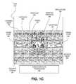
- FIG. 1Cillustrates a sonication cleaning method that may be utilized in accordance with embodiments of the present invention described herein.
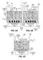
- FIG. 2Aillustrates a method of sonication cleaning with dwelling of disk(s) at one or more oscillation positions performed in accordance with one embodiment of the present invention.
- FIG. 2Billustrates a method of rinse cleaning with dwelling of disk(s) at one or more oscillation positions performed in accordance with one embodiment of the present invention.
- FIG. 2Cillustrates another embodiment of the present invention in which power to sonication plate transducers may be turned off during the rinse cleaning of disk(s) while dwelling at one or more oscillation positions.
- FIG. 3is a block diagram illustrating a cleaning control system according to one embodiment of the present invention.
- FIG. 4illustrates a cleaning system that may utilize one or more cleaning tanks and methods according to embodiments of the present invention.
- a methodincludes oscillating workpieces while performing a cleaning operation (e.g., sonication, rinse, etc.) and dwelling the workpieces at one or more oscillation positions (e.g., an upper oscillation position, a lower oscillation position, or an intermediate oscillation position) for a corresponding one or more dwell time periods.
- the dwell time periods at each of the oscillation positions at which the oscillation is dwelledi.e., a dwell position
- the dwell time periods in each of the oscillation cyclesmay be the same or different.
- FIG. 1Cillustrates a sonication cleaning method that may be utilized in accordance with embodiments of the present invention described herein. Embodiments of the cleaning methods may be described herein at times with respect to megasonication.
- sonciation plate transducers 250vibrate to generate acoustic waves 249 that produce a controlled acoustic stream 251 of cleaning liquid 235 in tank 215 towards disk(s) 201 .
- the acoustic waves 249produce cavitations 257 in the cleaning liquid 235 that move across the surface of the disk(s) 201 .
- the cavitations 257 that are producedhave sufficient energy to overcome the force of adhesion of some of the particles 258 residing on the surface of the disk(s) 201 and, thereby, remove particles 256 from the surface of the disk(s) 201 .
- the acoustic stream 251operates to move the removed particles 256 away from the disk(s) 201 in order to avoid the re-deposition of the particles 256 onto the surface of the disk(s) 201 .
- the cleaning method of the present inventionmay also include agitation cleaning of the disk(s) 201 , during sonication cleaning, by oscillations 261 of the disk(s) 201 to further facilitate removal of particles 256 .
- a circulation cross flow 240 of cleaning liquid 235may also be used during sonication cleaning in order to yet further facilitate the removal of particles 246 from the disk(s) 201 , as well as their movement away from disk(s) 201 to avoid their re-deposition on the surface of disk(s) 201 .
- Cleaning mechanismthat may operate on the workpieces during embodiments of the cleaning methods described herein may include one or more of the following: oscillation shear force, cross flow shear force, sonication cavitations collapse, and sonication AE agitation.
- oscillation shear forceFor example, in an embodiment that utilizes a cross flow 240 of cleaning liquid during sonication, such a cross flow 240 of cleaning liquid 235 in tank 214 may be become distorted and weaken the laminar flow strength of the cleaning liquid if the oscillation 260 velocity is too high. Yet, a stronger cross flow velocity may be desired as it could help particle removal (e.g., by shear force) and minimize particle re-deposition.
- the dwelling 262 of the workpieces at one or more of the oscillation positionsmay enable the strength of the cross flow 240 of cleaning liquid 235 to be maintained, for its generated velocity, in order to improve both the particle removal and particle re-deposition performance (i.e., reduce particle re-deposition).
- a benefit of utilizing a dwell period at an oscillation dwell positionmay be to allow higher sonication power at a dwell position having a stronger cleaning liquid cross flow 240 .
- the strength of the cross flow 240 of the cleaning liquid 235may limit the effect of the sonication power at certain oscillation positions. If the sonication acoustic stream 251 is stronger than the cross flow 240 at certain oscillation positions, the acoustic waves 249 may generate an additional sonication flow turbulence, which may degrade particle re-deposition performance.
- a stronger cross flow 240 of cleaning liquid enabled by a dwelling for dwell period at a dwell positioncould allow higher sonication power without being in the sonication turbulence regime and, thereby, enhance particle removal efficiency.
- the above noted four cleaning mechanismsmay be optimize in accordance with one embodiment of the present invention. It should be noted that embodiments of the present invention discussed herein are not limited only to purposes of providing the exemplary benefits noted above but may also be utilized for other purposes and benefits.
- FIG. 2Aillustrates a method of sonication cleaning with dwelling of disk(s) at one or more oscillation positions performed in accordance with one embodiment of the present invention.
- the disk(s) 201are lowered by a shuttle into tank 215 such that the disk(s) 201 are submerged in cleaning liquid 235 .
- a cross flow 240 of the cleaning liquid 235is established in the tank 215 in order to remove cleaning liquid particles from a vicinity of the disk(s) 201 .
- Tank 215is equipped with sonication plate transducers 250 that can be activated, or powered on, under the control of a programmable controller, to generate an acoustic stream 251 emanating from the bottom of tank 215 towards the disk(s) 201 in direction 252 .
- the disk(s) 201are also oscillated 260 during sonication, in a parallel direction to the direction 252 of the acoustic stream 251 , to generate agitation cleaning of the disk(s) 201 .
- the oscillation of the disk(s) 201may be performed by a handler such as the one used to transport the disk(s) 201 into tank 215 or by other mechanisms (e.g., manually).
- the disk(s)may be oscillated at a velocity, for example, in a range of 1,000 millimeters per minute (mm/min) to 10,000 mm/min. Sonication equipment such as the plate transducers and controllers is known in the art; accordingly, a more detailed discussion is not provided.
- the oscillation 260 of the disk(s) 201may be temporarily halted such that the movement of disk(s) 201 is dwelled at one or more oscillation positions (i.e., dwell positions) within the oscillation cycle of movement.
- the movement of disk(s) 201may be dwelled at, for example, upper oscillation position 268 , lower oscillation 267 , or an intermediate oscillation position 266 , or a combination thereof in order to improve the efficiency of the sonication cleaning performed in the tank 215 .
- Certain cleaning tank systemsmay have different, or non-uniform, cleaning liquid 235 circulation cross flow 240 rates from the bottom of the tank 215 to the top of the cleaning liquid level in tank 215 due to limitations in the equipment that is used to generate the cross flows in tank 215 .
- Such non-uniform cross flow rates in combination with the distance between upper and lower oscillation positionse.g., upwards of 45 millimeters
- a reduction in the cross flow rate of cleaning liquid near the upper part of the oscillation path of the disk(s) 201may result in less amounts of particulate being removed from the disk(s) 201 .
- one method embodiment of the present inventionincludes dwelling at a lower oscillation position 267 for a lower dwell time (LDT) period in order to remove more particulates that may not otherwise be removed at the upper oscillation position 268 due to the reduced cross flow of cleaning liquid at position 268 .
- the lower oscillation position 267 in one oscillation cyclemay be different than the lower oscillation position used in another cycle.
- the other oscillation positionsmay also be different in different cycles.
- the movement of disk(s) 201 during oscillation 260may be dwelled for other reasons, at other oscillation positions and also at multiple oscillation positions.
- the movement of disk(s) 201 during oscillation 260may be dwelled at upper oscillation position 268 for an upper position dwell time (UDT) or at any intermediate oscillation position 266 for an intermediate position dwell time (IDT).
- the upper dwell time periodmay be in a range of 1 to 3 seconds
- the lower dwell time periodmay be in a range of 0 to 2 seconds
- the intermediate dwell time periodis in a range of 0.5 to 2.5 seconds.
- the ratio of time between the moving of disks(s) 201 and the total dwelling time of disks 201 at any of the dwell positions during the oscillation 260may be approximately 1:1. It should be noted that the dwell times and ratio provided above are only exemplary and that other dwell times and ratios may be used.
- the various parameters discussed hereinmay be varied within a cycle and among the oscillation cycles.
- the dwell time periodsmay be the same or varied from one oscillation cycle to another oscillation cycle.
- the sonication power that is used at the different oscillation positions, and when moving among the oscillation positionsmay also be varied within a cycle and also among the oscillation cycles.
- disk(s) 201may be sonicated at the lower oscillation position 267 at a different sonication power than at the upper oscillation position 268 .
- the sonication power during movement of the disk(s) 201 among the different oscillation positions at which the disk(s) are dwelledis lower than the sonication power used when the disk(s) are at one or more of the dwell positions.
- the sonication power during movement of the disk(s) during oscillation 260is in a range of 0 to 400 watts and the sonication power at one or more of the dwell positions (e.g., 266 , 267 , 268 ) is in a range of 100 to 800 watts.
- other power settings for the sonication plate transducers 250may be used at the various oscillation dwell positions.
- FIG. 2Billustrates a method of rinse cleaning with dwelling of disk(s) at one or more oscillation positions performed in accordance with one embodiment of the present invention.
- the disk(s) 201may undergo a rinse cleaning operation.
- the rinse cleaning operationmay be performed in the same tank as was used for sonication or, alternatively, may be performed in a different tank.
- tank 215 of FIG. 2Bmay either be the same tank 215 as was used to perform the sonication cleaning described in relation to FIG. 2A or may be a separate tank in which rinsing is performed.
- a cross flow 241 of the cleaning liquid 235may be generated in the tank 215 while the disk(s) 201 are further oscillated 261 in a manner that removes at least a portion of the disk(s) 201 from submersion in the cleaning liquid 235 .
- the cross flow 241 of cleaning liquid 235is perpendicular to the direction of oscillating 261 .
- the cross flow 241 during the rinse cleaning of FIG. 2Bmay be set to have the same velocity as the cross flow 240 during the sonication cleaning of FIG. 2A or may be set to lower velocity to reduce dispersal of particulates in the cleaning solution.
- the cross flows 240 and 241 of the cleaning liquid 235 in either cleaning modesmay have a velocity in a range of 5 to 30 millimeters per second.
- no cross flow or other configurations of flow of cleaning liquid 235may be used during rinse cleaning of the disk(s) 201 .
- the disk(s) 201Before initiating further oscillation 261 during the rinse cleaning, the disk(s) 201 may be positioned at a lower oscillation, or reference position 271 such that they are completely submerged in the cleaning liquid 235 . During further oscillation 261 , the disk(s) 201 may be moved to an upper oscillation, or offset, position 272 . In one embodiment, the offset position 272 may be set such that the disk(s) 201 are completely removed from submersion in the cleaning liquid 235 as illustrated in FIG. 2B . Alternatively, the offset position 272 may be set such that the disk(s) 201 are only partially removed from submersion in the cleaning liquid 235 .
- the initial reference position 271may correspond with the lower oscillation position 267 at which the disk(s) are oscillated 260 during the sonication illustrated in FIG. 2A .
- the reference position 271may be set to a different position.
- a higher, upper oscillation positionmay be set for the disk(s) 201 to the desired offset position 272 for rinsing to enable the disk(s) to be lifted at least partially above the surface of the cleaning liquid 235 .
- the difference 273 between the offset position 272 and the reference position 271may be in a range of 80 to 100 millimeters. Alternatively, other difference distances may be used.
- the disk(s) 201may be oscillated at either the same or a different velocity when moved toward the offset position 272 than when moved toward to the reference position 271 . In one embodiment, for example, the disk(s) 201 are oscillated at a slower velocity when moved toward the reference position 271 than when moved toward the offset position 272 .
- the disk(s) 201may be oscillated during rinsing at the same velocity of oscillation as during sonication.
- the further oscillation of the disk(s) 201 during the rinsing of FIG. 2Bmay be at a lower velocity than during the sonication of FIG. 2A , for example, at a velocity in a range of 1,000 to 3,000 millimeters per minute (mm/min).
- the disk(s)may be further oscillated during rinsing at the same or greater velocity of oscillation than during sonication cleaning of FIG. 2A .
- the sonication plate transducers 250may be maintained powered on to continue the acoustic stream 251 either at a same power setting as used during the sonication cleaning of FIG. 2A or at a reduced power via a programmable controller.
- the sonication power settingsmay be different when the disk(s) 201 are at the upper and lower oscillation positions.
- the sonication power at the reference position 271may be in a range of 100 to 600 watts and, the sonication power at the offset position 272 may be in range of 0 to 300 watts. Alternatively, other power settings may be used.
- power to the sonication plate transducers 250may be turned off during the rinse cleaning of disk(s) such that no acoustic stream is generated 259 as illustrated in FIG. 2C .
- the relationship between the dwell times URPDT, IRPDT and LRPDT at the upper, intermediate and lower subsequent oscillation positions, respectively, during the rinse cleaning illustrated of FIG. 2Bmay be different than the dwell times (UDT, IDT, and LDT) during the sonication cleaning of FIG. 2A .
- the cleaning liquid 235 in the tank during rinsingmay be set to have a lower cross flow 241 velocity than during sonication.
- the ratio of time between moving the disk(s) 201 among the dwell positions and the total dwelling time (e.g., URPDT+IRPDT+LRPDT) at the various dwelling positions during rinsingis approximately 3:1.
- FIGS. 2A-2Ccertain mechanical components such as a shuttle and a handler that hold and oscillate the disk(s) are not illustrated in the above described FIGS. 2A-2C so as not to obscure an illustration of the described methods but, rather, are illustrated in the cleaning system of FIG. 3 , discussed below.
- FIG. 3is a block diagram illustrating a cleaning control system 300 according to one embodiment of the present invention.
- a system controllersuch as programmable logic controller (PLC) 395 is used to control the operation of the various subsystem controllers, generators, and components.
- the PLC 395is coupled to sonication generator 360 to control the operation (e.g., power settings and frequencies) of sonication plate transducers 250 through a user input panel 365 .
- the sonicationmay be performed at a cavitations frequency in a range of 120 to 950 kHz.
- the sonicationmay have a power setting in a range of 100 to 800 watts. It should be noted that power and frequencies provide herein are only exemplary and may have other values in alternative embodiments.
- a usermay program the PLC 360 , through input panel 365 , with different power settings at different stages of the cleaning operations discussed above.
- the sonication plate transducers 250under control of PLC 395 , generate an acoustic stream in the cleaning liquid 235 of tank 215 .
- the same PLC 395may be coupled to the sonication plate transducers of both the first cleaning tank 410 and second cleaning tank 420 of FIG. 4 discusses below.
- each of the first and second cleaning tanksmay have their own respective PLCs.
- the cleaning control system 300also includes a shuttle handler controller 380 coupled to handler 385 which, in turn, is coupled to disk(s) 201 carrying shuttle 225 .
- the shuttle handler controller 380controls the submersion and removal 386 of disk(s) into tank 215 and the transfer of the shuttle 225 between tanks (e.g., tanks 410 and 420 of FIG. 4 ).
- the shuttle handler controller 380also controls the oscillation 260 and dwelling of the disk(s) 201 during either sonication or rinse cleaning operations.
- the cleaning control system 300also includes a cross flow generator 390 to generate a cross flow of cleaning liquid 235 within tank 215 as discussed above.
- the cross flow generator 390includes components to generate cross the cross flows of cleaning liquid described above, for example, a pump to drive the cross flows of cleaning liquid, a valve to control the flow rates, and perforated side panels on tank 215 designed to control the desired laminar cross flow.
- Shuttle handler controllers, cross flow generators, PLCs and sonication plate transducersare known to those of ordinary skill in the art; accordingly, further details are not provided herein.
- the various components for the cleaning systemsare commercially available, for example, the PLC may be obtained from Controls Technology (CTC) or Mitsubishi; the sonication plate transducers and generator may be obtained from Branson or Crest; the shuttle handler and controller may be obtained from Star Linear System; and the cross flow generator and tank may be obtained from SpeedFam Corp.
- CTCControls Technology
- Mitsubishithe sonication plate transducers and generator
- the shuttle handler and controllermay be obtained from Star Linear System;
- the cross flow generator and tankmay be obtained from SpeedFam Corp.
- FIG. 4illustrates a cleaning system that may utilize one or more cleaning tanks and methods according to embodiments of the present invention.
- the cleaning system 400 of FIG. 4includes a first cleaning tank 410 in which either sonication cleaning alone may be performed or both sonication cleaning and rinse cleaning operations are combined.
- the cleaning system 400also includes a second tank 420 in which rinse cleaning may be performed.
- a cross flowe.g., 240 , 241
- cleaning liquid 235may be used during rinse cleaning of the disk(s) 201 .
- a cross flow of cleaning liquid 235may not be used during rinse cleaning of disk(s) 201 .
- the cleaning system 400 of FIG. 4may also include a dryer tank 430 .
- drying operationsmay not necessarily be a part of embodiments of the present invention, such is provided as a context for discussion of the sonication and rinse tanks.
- a shuttlemay be used to hold the disks during the cleaning operations and while the disks are carried to and from the tanks illustrated in FIG. 4 by a disk transport mechanism as discussed above.
- the sonication energy applied to the cleaning liquid as described by the methods hereinmay be applied by any one of other various techniques including, for example, ultrasonication (i.e., a lower frequency sonication than megasonication), or other acoustic energy generation mechanisms that generate cavitations such as the sonication plate transducers discussed herein.
- ultrasonicationi.e., a lower frequency sonication than megasonication
- megasonics cleaningi.e., a lower frequency sonication than megasonication
- a difference between ultrasonic cleaning and megasonics cleaninglies in the frequency that is used to generate the acoustic waves. Ultrasonic cleaning uses lower frequencies and, thereby, produces more random cavitations.
- Megasonics cleaninguses higher frequencies (e.g., on the order of several hundred to several thousand kHz in contrast with frequencies on the order of less than several hundred kHz for ultrasonics) and, thereby, produces more controlled cavitations. It should be noted that the megasonic and ultrasonic frequency ranges provided above are only examples and that those of ordinary skill in the art may consider megasonication or ultrasonic to have different frequencies than those noted above.
- a Branson ultrasonic generatormay be used for sonication cleaning methods discussed herein.
- the cleaning methods described hereinmay be utilized for post sputter wet cleaning (PSC) of magnetic recording disks.
- the magnetic recording diskincludes a magnetic recording layer deposited above a substrate.
- the magnetic layermay be of any known composition, such as a cobalt (Co) alloy.
- the magnetic layermay be formed on both sides of magnetic recording disk substrate to form a double-sided magnetic recording disk. Alternatively, a single sided magnetic recording disk may be formed.
- the magnetic recording disk substratemay be, for example, a glass material, a metal, and/or a metal alloy material.
- Glass substrates that may be usedinclude, for example, silica containing glass such as borosilicate glass and aluminosilicate glass.
- Metal and metal alloy substrates that may be usedinclude, for example, aluminum (Al) and aluminum magnesium (AIMg) substrates, respectively.
- the magnetic recording disk substratemay also be plated with a nickel phosphorous (NiP) layer.
- the cleaning methods described hereinmay be used in other pre or post fabrication operation cleans of partially or fully fabricated magnetic recording disks.
- Embodiments of cleaning methodsare described with respect to magnetic recording disks. It should be appreciated that the embodiments of cleaning methods described herein may be applied to disks that vary in size or shape, for the production of different size disks. Embodiments of cleaning methods described herein may also be used for the cleaning of semiconductor wafers or other types of workpieces.
- workpieceas used herein may include, substrates, semiconductor wafers, photomasks, magnetic recording disks, optical discs, glass substrates, flat panel display surfaces, liquid crystal display surfaces, etc.
Landscapes
- Engineering & Computer Science (AREA)
- Manufacturing & Machinery (AREA)
- Physics & Mathematics (AREA)
- Condensed Matter Physics & Semiconductors (AREA)
- General Physics & Mathematics (AREA)
- Computer Hardware Design (AREA)
- Microelectronics & Electronic Packaging (AREA)
- Power Engineering (AREA)
- Cleaning By Liquid Or Steam (AREA)
Abstract
Description
Claims (32)
Priority Applications (1)
| Application Number | Priority Date | Filing Date | Title |
|---|---|---|---|
| US12/369,701US8163093B1 (en) | 2009-02-11 | 2009-02-11 | Cleaning operations with dwell time |
Applications Claiming Priority (1)
| Application Number | Priority Date | Filing Date | Title |
|---|---|---|---|
| US12/369,701US8163093B1 (en) | 2009-02-11 | 2009-02-11 | Cleaning operations with dwell time |
Publications (1)
| Publication Number | Publication Date |
|---|---|
| US8163093B1true US8163093B1 (en) | 2012-04-24 |
Family
ID=45953473
Family Applications (1)
| Application Number | Title | Priority Date | Filing Date |
|---|---|---|---|
| US12/369,701Expired - Fee RelatedUS8163093B1 (en) | 2009-02-11 | 2009-02-11 | Cleaning operations with dwell time |
Country Status (1)
| Country | Link |
|---|---|
| US (1) | US8163093B1 (en) |
Cited By (70)
| Publication number | Priority date | Publication date | Assignee | Title |
|---|---|---|---|---|
| US20110026162A1 (en)* | 2008-03-30 | 2011-02-03 | Hoya Corporation | Magnetic disk and method of manufacturing the same |
| US8562748B1 (en) | 2009-01-30 | 2013-10-22 | WD Media, LLC | Multiple cleaning processes in a single tank |
| US8828566B2 (en) | 2010-05-21 | 2014-09-09 | Wd Media (Singapore) Pte. Ltd. | Perpendicular magnetic recording disc |
| US8859118B2 (en) | 2010-01-08 | 2014-10-14 | Wd Media (Singapore) Pte. Ltd. | Perpendicular magnetic recording medium |
| US8867322B1 (en) | 2013-05-07 | 2014-10-21 | WD Media, LLC | Systems and methods for providing thermal barrier bilayers for heat assisted magnetic recording media |
| US8877359B2 (en) | 2008-12-05 | 2014-11-04 | Wd Media (Singapore) Pte. Ltd. | Magnetic disk and method for manufacturing same |
| US8908315B2 (en) | 2010-03-29 | 2014-12-09 | Wd Media (Singapore) Pte. Ltd. | Evaluation method of magnetic disk, manufacturing method of magnetic disk, and magnetic disk |
| US8941950B2 (en) | 2012-05-23 | 2015-01-27 | WD Media, LLC | Underlayers for heat assisted magnetic recording (HAMR) media |
| US8947987B1 (en) | 2013-05-03 | 2015-02-03 | WD Media, LLC | Systems and methods for providing capping layers for heat assisted magnetic recording media |
| US8951651B2 (en) | 2010-05-28 | 2015-02-10 | Wd Media (Singapore) Pte. Ltd. | Perpendicular magnetic recording disk |
| US8980076B1 (en) | 2009-05-26 | 2015-03-17 | WD Media, LLC | Electro-deposited passivation coatings for patterned media |
| US8995078B1 (en) | 2014-09-25 | 2015-03-31 | WD Media, LLC | Method of testing a head for contamination |
| US8993134B2 (en) | 2012-06-29 | 2015-03-31 | Western Digital Technologies, Inc. | Electrically conductive underlayer to grow FePt granular media with (001) texture on glass substrates |
| US9001630B1 (en) | 2011-03-08 | 2015-04-07 | Western Digital Technologies, Inc. | Energy assisted magnetic recording medium capable of suppressing high DC readback noise |
| US9025264B1 (en) | 2011-03-10 | 2015-05-05 | WD Media, LLC | Methods for measuring media performance associated with adjacent track interference |
| US9028985B2 (en) | 2011-03-31 | 2015-05-12 | WD Media, LLC | Recording media with multiple exchange coupled magnetic layers |
| US9029308B1 (en) | 2012-03-28 | 2015-05-12 | WD Media, LLC | Low foam media cleaning detergent |
| US9034492B1 (en) | 2013-01-11 | 2015-05-19 | WD Media, LLC | Systems and methods for controlling damping of magnetic media for heat assisted magnetic recording |
| US9042053B1 (en) | 2014-06-24 | 2015-05-26 | WD Media, LLC | Thermally stabilized perpendicular magnetic recording medium |
| US9047903B2 (en) | 2008-03-26 | 2015-06-02 | Wd Media (Singapore) Pte. Ltd. | Perpendicular magnetic recording medium and process for manufacture thereof |
| US9047880B1 (en) | 2011-12-20 | 2015-06-02 | WD Media, LLC | Heat assisted magnetic recording method for media having moment keeper layer |
| US9064521B1 (en) | 2011-03-25 | 2015-06-23 | WD Media, LLC | Manufacturing of hard masks for patterning magnetic media |
| US9082447B1 (en) | 2014-09-22 | 2015-07-14 | WD Media, LLC | Determining storage media substrate material type |
| US9093100B2 (en) | 2008-03-17 | 2015-07-28 | Wd Media (Singapore) Pte. Ltd. | Magnetic recording medium including tailored exchange coupling layer and manufacturing method of the same |
| US9093122B1 (en) | 2013-04-05 | 2015-07-28 | WD Media, LLC | Systems and methods for improving accuracy of test measurements involving aggressor tracks written to disks of hard disk drives |
| US9142241B2 (en) | 2009-03-30 | 2015-09-22 | Wd Media (Singapore) Pte. Ltd. | Perpendicular magnetic recording medium and method of manufacturing the same |
| US9153268B1 (en) | 2013-02-19 | 2015-10-06 | WD Media, LLC | Lubricants comprising fluorinated graphene nanoribbons for magnetic recording media structure |
| US9159350B1 (en) | 2014-07-02 | 2015-10-13 | WD Media, LLC | High damping cap layer for magnetic recording media |
| US9177585B1 (en) | 2013-10-23 | 2015-11-03 | WD Media, LLC | Magnetic media capable of improving magnetic properties and thermal management for heat-assisted magnetic recording |
| US9177586B2 (en) | 2008-09-30 | 2015-11-03 | WD Media (Singapore), LLC | Magnetic disk and manufacturing method thereof |
| US9183867B1 (en) | 2013-02-21 | 2015-11-10 | WD Media, LLC | Systems and methods for forming implanted capping layers in magnetic media for magnetic recording |
| US9190094B2 (en) | 2013-04-04 | 2015-11-17 | Western Digital (Fremont) | Perpendicular recording media with grain isolation initiation layer and exchange breaking layer for signal-to-noise ratio enhancement |
| US9196283B1 (en) | 2013-03-13 | 2015-11-24 | Western Digital (Fremont), Llc | Method for providing a magnetic recording transducer using a chemical buffer |
| US9218850B1 (en) | 2014-12-23 | 2015-12-22 | WD Media, LLC | Exchange break layer for heat-assisted magnetic recording media |
| US9227324B1 (en) | 2014-09-25 | 2016-01-05 | WD Media, LLC | Mandrel for substrate transport system with notch |
| US9240204B2 (en) | 2010-05-21 | 2016-01-19 | Wd Media (Singapore) Pte. Ltd. | Perpendicular magnetic recording disc |
| US9257134B1 (en) | 2014-12-24 | 2016-02-09 | Western Digital Technologies, Inc. | Allowing fast data zone switches on data storage devices |
| US9269480B1 (en) | 2012-03-30 | 2016-02-23 | WD Media, LLC | Systems and methods for forming magnetic recording media with improved grain columnar growth for energy assisted magnetic recording |
| US9275669B1 (en) | 2015-03-31 | 2016-03-01 | WD Media, LLC | TbFeCo in PMR media for SNR improvement |
| US9280998B1 (en) | 2015-03-30 | 2016-03-08 | WD Media, LLC | Acidic post-sputter wash for magnetic recording media |
| US9296082B1 (en) | 2013-06-11 | 2016-03-29 | WD Media, LLC | Disk buffing apparatus with abrasive tape loading pad having a vibration absorbing layer |
| US9330685B1 (en) | 2009-11-06 | 2016-05-03 | WD Media, LLC | Press system for nano-imprinting of recording media with a two step pressing method |
| US9339978B1 (en) | 2009-11-06 | 2016-05-17 | WD Media, LLC | Press system with interleaved embossing foil holders for nano-imprinting of recording media |
| US9349404B2 (en) | 2010-05-28 | 2016-05-24 | Wd Media (Singapore) Pte. Ltd | Perpendicular magnetic recording disc |
| US9382496B1 (en) | 2013-12-19 | 2016-07-05 | Western Digital Technologies, Inc. | Lubricants with high thermal stability for heat-assisted magnetic recording |
| US9389135B2 (en) | 2013-09-26 | 2016-07-12 | WD Media, LLC | Systems and methods for calibrating a load cell of a disk burnishing machine |
| US9401300B1 (en) | 2014-12-18 | 2016-07-26 | WD Media, LLC | Media substrate gripper including a plurality of snap-fit fingers |
| US9406330B1 (en) | 2013-06-19 | 2016-08-02 | WD Media, LLC | Method for HDD disk defect source detection |
| US9406329B1 (en) | 2015-11-30 | 2016-08-02 | WD Media, LLC | HAMR media structure with intermediate layer underlying a magnetic recording layer having multiple sublayers |
| US9431045B1 (en) | 2014-04-25 | 2016-08-30 | WD Media, LLC | Magnetic seed layer used with an unbalanced soft underlayer |
| US9447368B1 (en) | 2014-02-18 | 2016-09-20 | WD Media, LLC | Detergent composition with low foam and high nickel solubility |
| US9449633B1 (en) | 2014-11-06 | 2016-09-20 | WD Media, LLC | Smooth structures for heat-assisted magnetic recording media |
| US9472227B2 (en) | 2010-06-22 | 2016-10-18 | Wd Media (Singapore) Pte. Ltd. | Perpendicular magnetic recording media and methods for producing the same |
| US9542968B1 (en) | 2010-08-20 | 2017-01-10 | WD Media, LLC | Single layer small grain size FePT:C film for heat assisted magnetic recording media |
| US20170018424A1 (en)* | 2014-04-17 | 2017-01-19 | Institute of Microelectronics, Chinese Academy of | Method for cleaning lanthanum gallium silicate wafer |
| US9558778B2 (en) | 2009-03-28 | 2017-01-31 | Wd Media (Singapore) Pte. Ltd. | Lubricant compound for magnetic disk and magnetic disk |
| US9581510B1 (en) | 2013-12-16 | 2017-02-28 | Western Digital Technologies, Inc. | Sputter chamber pressure gauge with vibration absorber |
| US9607646B2 (en) | 2013-07-30 | 2017-03-28 | WD Media, LLC | Hard disk double lubrication layer |
| US9685184B1 (en) | 2014-09-25 | 2017-06-20 | WD Media, LLC | NiFeX-based seed layer for magnetic recording media |
| US9818442B2 (en) | 2014-12-01 | 2017-11-14 | WD Media, LLC | Magnetic media having improved magnetic grain size distribution and intergranular segregation |
| US9824711B1 (en) | 2014-02-14 | 2017-11-21 | WD Media, LLC | Soft underlayer for heat assisted magnetic recording media |
| US9822441B2 (en) | 2015-03-31 | 2017-11-21 | WD Media, LLC | Iridium underlayer for heat assisted magnetic recording media |
| US9990940B1 (en) | 2014-12-30 | 2018-06-05 | WD Media, LLC | Seed structure for perpendicular magnetic recording media |
| US10054363B2 (en) | 2014-08-15 | 2018-08-21 | WD Media, LLC | Method and apparatus for cryogenic dynamic cooling |
| US10083715B2 (en) | 2010-05-28 | 2018-09-25 | WD Media (Singapore) Pte.Ltd. | Method of manufacturing a perpendicular magnetic disc |
| US10115428B1 (en) | 2013-02-15 | 2018-10-30 | Wd Media, Inc. | HAMR media structure having an anisotropic thermal barrier layer |
| US10121506B1 (en) | 2015-12-29 | 2018-11-06 | WD Media, LLC | Magnetic-recording medium including a carbon overcoat implanted with nitrogen and hydrogen |
| US10236026B1 (en) | 2015-11-06 | 2019-03-19 | WD Media, LLC | Thermal barrier layers and seed layers for control of thermal and structural properties of HAMR media |
| US11074934B1 (en) | 2015-09-25 | 2021-07-27 | Western Digital Technologies, Inc. | Heat assisted magnetic recording (HAMR) media with Curie temperature reduction layer |
| JP7655603B1 (en)* | 2024-07-19 | 2025-04-02 | 株式会社エスケーファイン | Cleaning method and cleaning device |
Citations (30)
| Publication number | Priority date | Publication date | Assignee | Title |
|---|---|---|---|---|
| US4736760A (en) | 1986-02-21 | 1988-04-12 | Robert A. Coberly | Apparatus for cleaning, rinsing and drying substrates |
| US4902350A (en) | 1987-09-09 | 1990-02-20 | Robert F. Orr | Method for rinsing, cleaning and drying silicon wafers |
| US4984597A (en) | 1984-05-21 | 1991-01-15 | Cfm Technologies Research Associates | Apparatus for rinsing and drying surfaces |
| US5071776A (en)* | 1987-11-28 | 1991-12-10 | Kabushiki Kaisha Toshiba | Wafer processsing method for manufacturing wafers having contaminant-gettering damage on one surface |
| US5090432A (en) | 1990-10-16 | 1992-02-25 | Verteq, Inc. | Single wafer megasonic semiconductor wafer processing system |
| US5169408A (en) | 1990-01-26 | 1992-12-08 | Fsi International, Inc. | Apparatus for wafer processing with in situ rinse |
| US5301701A (en) | 1992-07-30 | 1994-04-12 | Nafziger Charles P | Single-chamber cleaning, rinsing and drying apparatus and method therefor |
| US5317778A (en) | 1991-07-31 | 1994-06-07 | Shin-Etsu Handotai Co., Ltd. | Automatic cleaning apparatus for wafers |
| US5593505A (en) | 1995-04-19 | 1997-01-14 | Memc Electronic Materials, Inc. | Method for cleaning semiconductor wafers with sonic energy and passing through a gas-liquid-interface |
| US5725753A (en) | 1995-04-28 | 1998-03-10 | Pre-Tech Co., Ltd. | Apparatus and method for cleaning semiconductor wafers |
| US5727578A (en) | 1993-07-16 | 1998-03-17 | Legacy Systems, Inc. | Apparatus for the treatment and drying of semiconductor wafers in a fluid |
| US5776259A (en) | 1993-04-02 | 1998-07-07 | National Semiconductor Corporation | Method for final rinse/dry for critical cleaning application |
| US5849104A (en) | 1996-09-19 | 1998-12-15 | Yieldup International | Method and apparatus for cleaning wafers using multiple tanks |
| US5873947A (en) | 1994-11-14 | 1999-02-23 | Yieldup International | Ultra-low particle disk cleaner |
| US5881748A (en) | 1994-03-28 | 1999-03-16 | Shin-Etsu Handotai Co. Ltd. | Apparatus for rinsing wafers adhered with chemical liquid by use of purified water |
| US5911837A (en) | 1993-07-16 | 1999-06-15 | Legacy Systems, Inc. | Process for treatment of semiconductor wafers in a fluid |
| US5950643A (en) | 1995-09-06 | 1999-09-14 | Miyazaki; Takeshiro | Wafer processing system |
| US6108928A (en) | 1997-07-15 | 2000-08-29 | Samsung Electronics Co., Ltd. | Vacuum dryer of drying semiconductor device using the same |
| US20010013355A1 (en) | 1998-10-14 | 2001-08-16 | Busnaina Ahmed A. | Fast single-article megasonic cleaning process for single-sided or dual-sided cleaning |
| US20020139390A1 (en) | 2000-09-20 | 2002-10-03 | Shoichi Okano | Method for cleaning substrate and apparatus therefor |
| US6477786B1 (en) | 1999-05-27 | 2002-11-12 | Lam Research Corporation | Apparatus for drying batches of disks |
| US6575177B1 (en) | 1999-04-27 | 2003-06-10 | Applied Materials Inc. | Semiconductor substrate cleaning system |
| US6620260B2 (en) | 2000-05-15 | 2003-09-16 | Tokyo Electron Limited | Substrate rinsing and drying method |
| US6625901B1 (en) | 1999-05-27 | 2003-09-30 | Oliver Design, Inc. | Apparatus and method for drying a thin substrate |
| US20030234029A1 (en) | 2001-07-16 | 2003-12-25 | Semitool, Inc. | Cleaning and drying a substrate |
| US20070175496A1 (en) | 2006-01-31 | 2007-08-02 | Hitachi High-Technologies Corporation | Cleaning method with chemical agent and cleaning apparatus with chemical agent |
| US20070181159A1 (en) | 2006-02-03 | 2007-08-09 | Hitachi High-Technologies Corporation | Disk cleaning apparatus, disk immersing and extracting mechanism and disk cleaning method |
| WO2008056969A1 (en) | 2006-11-09 | 2008-05-15 | Invenpro (M) Sdn. Bhd. | Method for drying a substrate |
| US20080295860A1 (en) | 2006-12-15 | 2008-12-04 | Norbert Burger | Apparatus and Method for Cleaning of Objects, in Particular of Thin Discs |
| US20090165824A1 (en)* | 2007-12-26 | 2009-07-02 | Hitachi Global Strorage Technologies Netherlands B.V. | Cleaning apparatus for cleaning component part of magnetic disk drive and cleaning method of cleaning component part of magnetic disk drive |
- 2009
- 2009-02-11USUS12/369,701patent/US8163093B1/ennot_activeExpired - Fee Related
Patent Citations (31)
| Publication number | Priority date | Publication date | Assignee | Title |
|---|---|---|---|---|
| US4984597A (en) | 1984-05-21 | 1991-01-15 | Cfm Technologies Research Associates | Apparatus for rinsing and drying surfaces |
| US4984597B1 (en) | 1984-05-21 | 1999-10-26 | Cfmt Inc | Apparatus for rinsing and drying surfaces |
| US4736760A (en) | 1986-02-21 | 1988-04-12 | Robert A. Coberly | Apparatus for cleaning, rinsing and drying substrates |
| US4902350A (en) | 1987-09-09 | 1990-02-20 | Robert F. Orr | Method for rinsing, cleaning and drying silicon wafers |
| US5071776A (en)* | 1987-11-28 | 1991-12-10 | Kabushiki Kaisha Toshiba | Wafer processsing method for manufacturing wafers having contaminant-gettering damage on one surface |
| US5169408A (en) | 1990-01-26 | 1992-12-08 | Fsi International, Inc. | Apparatus for wafer processing with in situ rinse |
| US5090432A (en) | 1990-10-16 | 1992-02-25 | Verteq, Inc. | Single wafer megasonic semiconductor wafer processing system |
| US5317778A (en) | 1991-07-31 | 1994-06-07 | Shin-Etsu Handotai Co., Ltd. | Automatic cleaning apparatus for wafers |
| US5301701A (en) | 1992-07-30 | 1994-04-12 | Nafziger Charles P | Single-chamber cleaning, rinsing and drying apparatus and method therefor |
| US5776259A (en) | 1993-04-02 | 1998-07-07 | National Semiconductor Corporation | Method for final rinse/dry for critical cleaning application |
| US5911837A (en) | 1993-07-16 | 1999-06-15 | Legacy Systems, Inc. | Process for treatment of semiconductor wafers in a fluid |
| US5727578A (en) | 1993-07-16 | 1998-03-17 | Legacy Systems, Inc. | Apparatus for the treatment and drying of semiconductor wafers in a fluid |
| US5881748A (en) | 1994-03-28 | 1999-03-16 | Shin-Etsu Handotai Co. Ltd. | Apparatus for rinsing wafers adhered with chemical liquid by use of purified water |
| US5873947A (en) | 1994-11-14 | 1999-02-23 | Yieldup International | Ultra-low particle disk cleaner |
| US5593505A (en) | 1995-04-19 | 1997-01-14 | Memc Electronic Materials, Inc. | Method for cleaning semiconductor wafers with sonic energy and passing through a gas-liquid-interface |
| US5725753A (en) | 1995-04-28 | 1998-03-10 | Pre-Tech Co., Ltd. | Apparatus and method for cleaning semiconductor wafers |
| US5950643A (en) | 1995-09-06 | 1999-09-14 | Miyazaki; Takeshiro | Wafer processing system |
| US5849104A (en) | 1996-09-19 | 1998-12-15 | Yieldup International | Method and apparatus for cleaning wafers using multiple tanks |
| US6108928A (en) | 1997-07-15 | 2000-08-29 | Samsung Electronics Co., Ltd. | Vacuum dryer of drying semiconductor device using the same |
| US20010013355A1 (en) | 1998-10-14 | 2001-08-16 | Busnaina Ahmed A. | Fast single-article megasonic cleaning process for single-sided or dual-sided cleaning |
| US6575177B1 (en) | 1999-04-27 | 2003-06-10 | Applied Materials Inc. | Semiconductor substrate cleaning system |
| US6477786B1 (en) | 1999-05-27 | 2002-11-12 | Lam Research Corporation | Apparatus for drying batches of disks |
| US6625901B1 (en) | 1999-05-27 | 2003-09-30 | Oliver Design, Inc. | Apparatus and method for drying a thin substrate |
| US6620260B2 (en) | 2000-05-15 | 2003-09-16 | Tokyo Electron Limited | Substrate rinsing and drying method |
| US20020139390A1 (en) | 2000-09-20 | 2002-10-03 | Shoichi Okano | Method for cleaning substrate and apparatus therefor |
| US20030234029A1 (en) | 2001-07-16 | 2003-12-25 | Semitool, Inc. | Cleaning and drying a substrate |
| US20070175496A1 (en) | 2006-01-31 | 2007-08-02 | Hitachi High-Technologies Corporation | Cleaning method with chemical agent and cleaning apparatus with chemical agent |
| US20070181159A1 (en) | 2006-02-03 | 2007-08-09 | Hitachi High-Technologies Corporation | Disk cleaning apparatus, disk immersing and extracting mechanism and disk cleaning method |
| WO2008056969A1 (en) | 2006-11-09 | 2008-05-15 | Invenpro (M) Sdn. Bhd. | Method for drying a substrate |
| US20080295860A1 (en) | 2006-12-15 | 2008-12-04 | Norbert Burger | Apparatus and Method for Cleaning of Objects, in Particular of Thin Discs |
| US20090165824A1 (en)* | 2007-12-26 | 2009-07-02 | Hitachi Global Strorage Technologies Netherlands B.V. | Cleaning apparatus for cleaning component part of magnetic disk drive and cleaning method of cleaning component part of magnetic disk drive |
Non-Patent Citations (5)
| Title |
|---|
| Office Action dated Dec. 14, 2011 in U.S. Appl. No. 12/363,676, 13 pages. |
| Office Action dated Feb. 21, 2012 in U.S. Appl. No. 12/363,676, 4 pages. |
| Office Action dated Mar. 3, 2011 in U.S. Appl. No. 12/363,676, 10 pages. |
| U.S. Appl. No. 12/363,676, filed Jan. 30, 2009, 17 pages. |
| U.S. Office Action from U.S. Appl. No. 12/363,676 dated Aug. 12, 2011. |
Cited By (75)
| Publication number | Priority date | Publication date | Assignee | Title |
|---|---|---|---|---|
| US9093100B2 (en) | 2008-03-17 | 2015-07-28 | Wd Media (Singapore) Pte. Ltd. | Magnetic recording medium including tailored exchange coupling layer and manufacturing method of the same |
| US9047903B2 (en) | 2008-03-26 | 2015-06-02 | Wd Media (Singapore) Pte. Ltd. | Perpendicular magnetic recording medium and process for manufacture thereof |
| US9005782B2 (en) | 2008-03-30 | 2015-04-14 | WD Media, LLC | Magnetic disk and method of manufacturing the same |
| US20110026162A1 (en)* | 2008-03-30 | 2011-02-03 | Hoya Corporation | Magnetic disk and method of manufacturing the same |
| US9984715B2 (en) | 2008-09-30 | 2018-05-29 | WD Media, LLC | Magnetic disk and manufacturing method thereof |
| US9177586B2 (en) | 2008-09-30 | 2015-11-03 | WD Media (Singapore), LLC | Magnetic disk and manufacturing method thereof |
| US8877359B2 (en) | 2008-12-05 | 2014-11-04 | Wd Media (Singapore) Pte. Ltd. | Magnetic disk and method for manufacturing same |
| US9177601B1 (en) | 2009-01-30 | 2015-11-03 | WD Media, LLC | Multiple cleaning processes in a single tank |
| US8562748B1 (en) | 2009-01-30 | 2013-10-22 | WD Media, LLC | Multiple cleaning processes in a single tank |
| US9558778B2 (en) | 2009-03-28 | 2017-01-31 | Wd Media (Singapore) Pte. Ltd. | Lubricant compound for magnetic disk and magnetic disk |
| US9142241B2 (en) | 2009-03-30 | 2015-09-22 | Wd Media (Singapore) Pte. Ltd. | Perpendicular magnetic recording medium and method of manufacturing the same |
| US8980076B1 (en) | 2009-05-26 | 2015-03-17 | WD Media, LLC | Electro-deposited passivation coatings for patterned media |
| US9330685B1 (en) | 2009-11-06 | 2016-05-03 | WD Media, LLC | Press system for nano-imprinting of recording media with a two step pressing method |
| US9339978B1 (en) | 2009-11-06 | 2016-05-17 | WD Media, LLC | Press system with interleaved embossing foil holders for nano-imprinting of recording media |
| US8859118B2 (en) | 2010-01-08 | 2014-10-14 | Wd Media (Singapore) Pte. Ltd. | Perpendicular magnetic recording medium |
| US8908315B2 (en) | 2010-03-29 | 2014-12-09 | Wd Media (Singapore) Pte. Ltd. | Evaluation method of magnetic disk, manufacturing method of magnetic disk, and magnetic disk |
| US9240204B2 (en) | 2010-05-21 | 2016-01-19 | Wd Media (Singapore) Pte. Ltd. | Perpendicular magnetic recording disc |
| US8828566B2 (en) | 2010-05-21 | 2014-09-09 | Wd Media (Singapore) Pte. Ltd. | Perpendicular magnetic recording disc |
| US8951651B2 (en) | 2010-05-28 | 2015-02-10 | Wd Media (Singapore) Pte. Ltd. | Perpendicular magnetic recording disk |
| US9349404B2 (en) | 2010-05-28 | 2016-05-24 | Wd Media (Singapore) Pte. Ltd | Perpendicular magnetic recording disc |
| US10083715B2 (en) | 2010-05-28 | 2018-09-25 | WD Media (Singapore) Pte.Ltd. | Method of manufacturing a perpendicular magnetic disc |
| US9472227B2 (en) | 2010-06-22 | 2016-10-18 | Wd Media (Singapore) Pte. Ltd. | Perpendicular magnetic recording media and methods for producing the same |
| US9542968B1 (en) | 2010-08-20 | 2017-01-10 | WD Media, LLC | Single layer small grain size FePT:C film for heat assisted magnetic recording media |
| US9001630B1 (en) | 2011-03-08 | 2015-04-07 | Western Digital Technologies, Inc. | Energy assisted magnetic recording medium capable of suppressing high DC readback noise |
| US9025264B1 (en) | 2011-03-10 | 2015-05-05 | WD Media, LLC | Methods for measuring media performance associated with adjacent track interference |
| US9064521B1 (en) | 2011-03-25 | 2015-06-23 | WD Media, LLC | Manufacturing of hard masks for patterning magnetic media |
| US9028985B2 (en) | 2011-03-31 | 2015-05-12 | WD Media, LLC | Recording media with multiple exchange coupled magnetic layers |
| US9047880B1 (en) | 2011-12-20 | 2015-06-02 | WD Media, LLC | Heat assisted magnetic recording method for media having moment keeper layer |
| US9029308B1 (en) | 2012-03-28 | 2015-05-12 | WD Media, LLC | Low foam media cleaning detergent |
| US9269480B1 (en) | 2012-03-30 | 2016-02-23 | WD Media, LLC | Systems and methods for forming magnetic recording media with improved grain columnar growth for energy assisted magnetic recording |
| US8941950B2 (en) | 2012-05-23 | 2015-01-27 | WD Media, LLC | Underlayers for heat assisted magnetic recording (HAMR) media |
| US8993134B2 (en) | 2012-06-29 | 2015-03-31 | Western Digital Technologies, Inc. | Electrically conductive underlayer to grow FePt granular media with (001) texture on glass substrates |
| US9034492B1 (en) | 2013-01-11 | 2015-05-19 | WD Media, LLC | Systems and methods for controlling damping of magnetic media for heat assisted magnetic recording |
| US10115428B1 (en) | 2013-02-15 | 2018-10-30 | Wd Media, Inc. | HAMR media structure having an anisotropic thermal barrier layer |
| US9153268B1 (en) | 2013-02-19 | 2015-10-06 | WD Media, LLC | Lubricants comprising fluorinated graphene nanoribbons for magnetic recording media structure |
| US9183867B1 (en) | 2013-02-21 | 2015-11-10 | WD Media, LLC | Systems and methods for forming implanted capping layers in magnetic media for magnetic recording |
| US9196283B1 (en) | 2013-03-13 | 2015-11-24 | Western Digital (Fremont), Llc | Method for providing a magnetic recording transducer using a chemical buffer |
| US9190094B2 (en) | 2013-04-04 | 2015-11-17 | Western Digital (Fremont) | Perpendicular recording media with grain isolation initiation layer and exchange breaking layer for signal-to-noise ratio enhancement |
| US9093122B1 (en) | 2013-04-05 | 2015-07-28 | WD Media, LLC | Systems and methods for improving accuracy of test measurements involving aggressor tracks written to disks of hard disk drives |
| US8947987B1 (en) | 2013-05-03 | 2015-02-03 | WD Media, LLC | Systems and methods for providing capping layers for heat assisted magnetic recording media |
| US8867322B1 (en) | 2013-05-07 | 2014-10-21 | WD Media, LLC | Systems and methods for providing thermal barrier bilayers for heat assisted magnetic recording media |
| US9296082B1 (en) | 2013-06-11 | 2016-03-29 | WD Media, LLC | Disk buffing apparatus with abrasive tape loading pad having a vibration absorbing layer |
| US9406330B1 (en) | 2013-06-19 | 2016-08-02 | WD Media, LLC | Method for HDD disk defect source detection |
| US9607646B2 (en) | 2013-07-30 | 2017-03-28 | WD Media, LLC | Hard disk double lubrication layer |
| US9389135B2 (en) | 2013-09-26 | 2016-07-12 | WD Media, LLC | Systems and methods for calibrating a load cell of a disk burnishing machine |
| US9177585B1 (en) | 2013-10-23 | 2015-11-03 | WD Media, LLC | Magnetic media capable of improving magnetic properties and thermal management for heat-assisted magnetic recording |
| US9581510B1 (en) | 2013-12-16 | 2017-02-28 | Western Digital Technologies, Inc. | Sputter chamber pressure gauge with vibration absorber |
| US9382496B1 (en) | 2013-12-19 | 2016-07-05 | Western Digital Technologies, Inc. | Lubricants with high thermal stability for heat-assisted magnetic recording |
| US9824711B1 (en) | 2014-02-14 | 2017-11-21 | WD Media, LLC | Soft underlayer for heat assisted magnetic recording media |
| US9447368B1 (en) | 2014-02-18 | 2016-09-20 | WD Media, LLC | Detergent composition with low foam and high nickel solubility |
| US10964529B2 (en)* | 2014-04-17 | 2021-03-30 | Institute of Microelectronics, Chinese Academy of Sciences | Method for cleaning lanthanum gallium silicate wafer |
| US20170018424A1 (en)* | 2014-04-17 | 2017-01-19 | Institute of Microelectronics, Chinese Academy of | Method for cleaning lanthanum gallium silicate wafer |
| US9431045B1 (en) | 2014-04-25 | 2016-08-30 | WD Media, LLC | Magnetic seed layer used with an unbalanced soft underlayer |
| US9042053B1 (en) | 2014-06-24 | 2015-05-26 | WD Media, LLC | Thermally stabilized perpendicular magnetic recording medium |
| US9159350B1 (en) | 2014-07-02 | 2015-10-13 | WD Media, LLC | High damping cap layer for magnetic recording media |
| US10054363B2 (en) | 2014-08-15 | 2018-08-21 | WD Media, LLC | Method and apparatus for cryogenic dynamic cooling |
| US9082447B1 (en) | 2014-09-22 | 2015-07-14 | WD Media, LLC | Determining storage media substrate material type |
| US9227324B1 (en) | 2014-09-25 | 2016-01-05 | WD Media, LLC | Mandrel for substrate transport system with notch |
| US9685184B1 (en) | 2014-09-25 | 2017-06-20 | WD Media, LLC | NiFeX-based seed layer for magnetic recording media |
| US8995078B1 (en) | 2014-09-25 | 2015-03-31 | WD Media, LLC | Method of testing a head for contamination |
| US9449633B1 (en) | 2014-11-06 | 2016-09-20 | WD Media, LLC | Smooth structures for heat-assisted magnetic recording media |
| US10783915B2 (en) | 2014-12-01 | 2020-09-22 | Western Digital Technologies, Inc. | Magnetic media having improved magnetic grain size distribution and intergranular segregation |
| US9818442B2 (en) | 2014-12-01 | 2017-11-14 | WD Media, LLC | Magnetic media having improved magnetic grain size distribution and intergranular segregation |
| US9401300B1 (en) | 2014-12-18 | 2016-07-26 | WD Media, LLC | Media substrate gripper including a plurality of snap-fit fingers |
| US9218850B1 (en) | 2014-12-23 | 2015-12-22 | WD Media, LLC | Exchange break layer for heat-assisted magnetic recording media |
| US9257134B1 (en) | 2014-12-24 | 2016-02-09 | Western Digital Technologies, Inc. | Allowing fast data zone switches on data storage devices |
| US9990940B1 (en) | 2014-12-30 | 2018-06-05 | WD Media, LLC | Seed structure for perpendicular magnetic recording media |
| US9280998B1 (en) | 2015-03-30 | 2016-03-08 | WD Media, LLC | Acidic post-sputter wash for magnetic recording media |
| US9275669B1 (en) | 2015-03-31 | 2016-03-01 | WD Media, LLC | TbFeCo in PMR media for SNR improvement |
| US9822441B2 (en) | 2015-03-31 | 2017-11-21 | WD Media, LLC | Iridium underlayer for heat assisted magnetic recording media |
| US11074934B1 (en) | 2015-09-25 | 2021-07-27 | Western Digital Technologies, Inc. | Heat assisted magnetic recording (HAMR) media with Curie temperature reduction layer |
| US10236026B1 (en) | 2015-11-06 | 2019-03-19 | WD Media, LLC | Thermal barrier layers and seed layers for control of thermal and structural properties of HAMR media |
| US9406329B1 (en) | 2015-11-30 | 2016-08-02 | WD Media, LLC | HAMR media structure with intermediate layer underlying a magnetic recording layer having multiple sublayers |
| US10121506B1 (en) | 2015-12-29 | 2018-11-06 | WD Media, LLC | Magnetic-recording medium including a carbon overcoat implanted with nitrogen and hydrogen |
| JP7655603B1 (en)* | 2024-07-19 | 2025-04-02 | 株式会社エスケーファイン | Cleaning method and cleaning device |
Similar Documents
| Publication | Publication Date | Title |
|---|---|---|
| US8163093B1 (en) | Cleaning operations with dwell time | |
| US9177601B1 (en) | Multiple cleaning processes in a single tank | |
| US9296022B1 (en) | Sonication cleaning system | |
| US8596287B1 (en) | Cross flow tank | |
| US8327861B2 (en) | Megasonic precision cleaning of semiconductor process equipment components and parts | |
| JP4934739B2 (en) | Ultrasonic cleaning apparatus and ultrasonic cleaning method | |
| US20030010356A1 (en) | Single wafer megasonic cleaner method, system, and apparatus | |
| JP5449953B2 (en) | Substrate processing apparatus and substrate processing method | |
| KR20120095787A (en) | Substrate cleaning apparatus, substrate cleaning method, display manufacturing apparatus and display manufacturing method | |
| KR101581073B1 (en) | Method of particle contaminant removal | |
| WO2007085015A3 (en) | Acoustic energy system, method and apparatus for processing flat articles | |
| KR20150111818A (en) | Substrate cleaning method and substrate cleaning apparatus | |
| JP2010149003A (en) | Liquid-scattering prevention cup of substrate processing apparatus, substrate processing apparatus and method for operating the apparatus | |
| US20070084481A1 (en) | System and method of cleaning substrates using a subambient process solution | |
| JP2000070885A (en) | Device and method for cleaning substrate | |
| JP2005347761A (en) | Substrate-cleaning device and substrate-cleaning method | |
| JP2010524234A5 (en) | ||
| WO2014184999A1 (en) | Ultrasonic cleaning apparatus and cleaning method | |
| JP6233570B2 (en) | Wafer cleaning equipment | |
| JP2009113004A (en) | Cleaning method and cleaning apparatus | |
| JP4334813B2 (en) | Substrate cleaning apparatus and substrate cleaning method | |
| JP4007742B2 (en) | Ultrasonic cleaning method | |
| JP2011165911A (en) | Cleaning apparatus, method for cleaning object to be cleaned, and method for oscillating ultrasonic waves | |
| JP2017112140A (en) | Substrate processing apparatus | |
| JP2009208005A (en) | Ultrasonic washing apparatus |
Legal Events
| Date | Code | Title | Description |
|---|---|---|---|
| AS | Assignment | Owner name:WD MEDIA, INC., CALIFORNIA Free format text:ASSIGNMENT OF ASSIGNORS INTEREST;ASSIGNORS:CHEN, CHAOYUAN;CHEN, SHAUN;REEL/FRAME:022535/0618 Effective date:20090216 | |
| STCF | Information on status: patent grant | Free format text:PATENTED CASE | |
| FPAY | Fee payment | Year of fee payment:4 | |
| AS | Assignment | Owner name:JPMORGAN CHASE BANK, N.A., AS COLLATERAL AGENT, ILLINOIS Free format text:SECURITY AGREEMENT;ASSIGNOR:WD MEDIA, LLC;REEL/FRAME:038709/0879 Effective date:20160512 Owner name:U.S. BANK NATIONAL ASSOCIATION, AS COLLATERAL AGENT, CALIFORNIA Free format text:SECURITY AGREEMENT;ASSIGNOR:WD MEDIA, LLC;REEL/FRAME:038709/0931 Effective date:20160512 Owner name:JPMORGAN CHASE BANK, N.A., AS COLLATERAL AGENT, ILLINOIS Free format text:SECURITY AGREEMENT;ASSIGNOR:WD MEDIA, LLC;REEL/FRAME:038710/0383 Effective date:20160512 Owner name:U.S. BANK NATIONAL ASSOCIATION, AS COLLATERAL AGEN Free format text:SECURITY AGREEMENT;ASSIGNOR:WD MEDIA, LLC;REEL/FRAME:038709/0931 Effective date:20160512 Owner name:JPMORGAN CHASE BANK, N.A., AS COLLATERAL AGENT, IL Free format text:SECURITY AGREEMENT;ASSIGNOR:WD MEDIA, LLC;REEL/FRAME:038709/0879 Effective date:20160512 Owner name:JPMORGAN CHASE BANK, N.A., AS COLLATERAL AGENT, IL Free format text:SECURITY AGREEMENT;ASSIGNOR:WD MEDIA, LLC;REEL/FRAME:038710/0383 Effective date:20160512 | |
| AS | Assignment | Owner name:WD MEDIA, LLC, CALIFORNIA Free format text:RELEASE BY SECURED PARTY;ASSIGNOR:U.S. BANK NATIONAL ASSOCIATION, AS COLLATERAL AGENT;REEL/FRAME:045501/0672 Effective date:20180227 | |
| AS | Assignment | Owner name:WD MEDIA, LLC, CALIFORNIA Free format text:CHANGE OF NAME;ASSIGNOR:WD MEDIA, INC;REEL/FRAME:047112/0758 Effective date:20111230 | |
| AS | Assignment | Owner name:WESTERN DIGITAL TECHNOLOGIES, INC., CALIFORNIA Free format text:ASSIGNMENT OF ASSIGNORS INTEREST;ASSIGNOR:WD MEDIA, LLC;REEL/FRAME:049084/0826 Effective date:20190423 | |
| FEPP | Fee payment procedure | Free format text:MAINTENANCE FEE REMINDER MAILED (ORIGINAL EVENT CODE: REM.); ENTITY STATUS OF PATENT OWNER: LARGE ENTITY | |
| LAPS | Lapse for failure to pay maintenance fees | Free format text:PATENT EXPIRED FOR FAILURE TO PAY MAINTENANCE FEES (ORIGINAL EVENT CODE: EXP.); ENTITY STATUS OF PATENT OWNER: LARGE ENTITY | |
| STCH | Information on status: patent discontinuation | Free format text:PATENT EXPIRED DUE TO NONPAYMENT OF MAINTENANCE FEES UNDER 37 CFR 1.362 | |
| FP | Lapsed due to failure to pay maintenance fee | Effective date:20200424 | |
| AS | Assignment | Owner name:WESTERN DIGITAL TECHNOLOGIES, INC., CALIFORNIA Free format text:RELEASE OF SECURITY INTEREST AT REEL 038710 FRAME 0383;ASSIGNOR:JPMORGAN CHASE BANK, N.A.;REEL/FRAME:058965/0410 Effective date:20220203 Owner name:WD MEDIA, LLC, CALIFORNIA Free format text:RELEASE OF SECURITY INTEREST AT REEL 038710 FRAME 0383;ASSIGNOR:JPMORGAN CHASE BANK, N.A.;REEL/FRAME:058965/0410 Effective date:20220203 |