US8163026B2 - Interbody implant - Google Patents
Interbody implantDownload PDFInfo
- Publication number
- US8163026B2 US8163026B2US11/697,108US69710807AUS8163026B2US 8163026 B2US8163026 B2US 8163026B2US 69710807 AUS69710807 AUS 69710807AUS 8163026 B2US8163026 B2US 8163026B2
- Authority
- US
- United States
- Prior art keywords
- implant
- members
- insertion tool
- connection portion
- disc space
- Prior art date
- Legal status (The legal status is an assumption and is not a legal conclusion. Google has not performed a legal analysis and makes no representation as to the accuracy of the status listed.)
- Expired - Fee Related, expires
Links
- 239000007943implantSubstances0.000titleclaimsabstractdescription118
- 238000003780insertionMethods0.000claimsdescription45
- 230000037431insertionEffects0.000claimsdescription45
- 238000000034methodMethods0.000claimsdescription30
- 230000033001locomotionEffects0.000claimsdescription10
- 230000013011matingEffects0.000claimsdescription8
- 210000000988bone and boneAnatomy0.000description43
- 239000000463materialSubstances0.000description12
- 230000008468bone growthEffects0.000description6
- 238000000926separation methodMethods0.000description5
- 238000001356surgical procedureMethods0.000description5
- 230000004927fusionEffects0.000description4
- 239000004696Poly ether ether ketoneSubstances0.000description3
- RTAQQCXQSZGOHL-UHFFFAOYSA-NTitaniumChemical compound[Ti]RTAQQCXQSZGOHL-UHFFFAOYSA-N0.000description3
- 238000013459approachMethods0.000description3
- 230000014759maintenance of locationEffects0.000description3
- 229910052751metalInorganic materials0.000description3
- 239000002184metalSubstances0.000description3
- 229920002530polyetherether ketonePolymers0.000description3
- 229920000642polymerPolymers0.000description3
- 239000010936titaniumSubstances0.000description3
- 229910052719titaniumInorganic materials0.000description3
- 230000008901benefitEffects0.000description2
- -1but not limited toChemical class0.000description2
- 239000000919ceramicSubstances0.000description2
- 230000001054cortical effectEffects0.000description2
- 229910052588hydroxylapatiteInorganic materials0.000description2
- 150000002739metalsChemical class0.000description2
- 210000005036nerveAnatomy0.000description2
- XYJRXVWERLGGKC-UHFFFAOYSA-Dpentacalcium;hydroxide;triphosphateChemical compound[OH-].[Ca+2].[Ca+2].[Ca+2].[Ca+2].[Ca+2].[O-]P([O-])([O-])=O.[O-]P([O-])([O-])=O.[O-]P([O-])([O-])=OXYJRXVWERLGGKC-UHFFFAOYSA-D0.000description2
- 229920000049Carbon (fiber)Polymers0.000description1
- 208000028389Nerve injuryDiseases0.000description1
- 208000008558OsteophyteDiseases0.000description1
- 229920002732PolyanhydridePolymers0.000description1
- 229910001069Ti alloyInorganic materials0.000description1
- 230000032683agingEffects0.000description1
- 230000004075alterationEffects0.000description1
- 239000000560biocompatible materialSubstances0.000description1
- 230000000740bleeding effectEffects0.000description1
- 239000004917carbon fiberSubstances0.000description1
- 210000003164cauda equinaAnatomy0.000description1
- 239000011248coating agentSubstances0.000description1
- 238000000576coating methodMethods0.000description1
- 230000006378damageEffects0.000description1
- 230000002950deficientEffects0.000description1
- 230000007850degenerationEffects0.000description1
- 230000001419dependent effectEffects0.000description1
- 230000001687destabilizationEffects0.000description1
- 238000011161developmentMethods0.000description1
- 230000018109developmental processEffects0.000description1
- 201000010099diseaseDiseases0.000description1
- 208000037265diseases, disorders, signs and symptomsDiseases0.000description1
- 208000014674injuryDiseases0.000description1
- 238000012966insertion methodMethods0.000description1
- 230000001788irregularEffects0.000description1
- VNWKTOKETHGBQD-UHFFFAOYSA-NmethaneChemical compoundCVNWKTOKETHGBQD-UHFFFAOYSA-N0.000description1
- 238000002324minimally invasive surgeryMethods0.000description1
- 239000000203mixtureSubstances0.000description1
- 230000008764nerve damageEffects0.000description1
- 210000000944nerve tissueAnatomy0.000description1
- 238000010883osseointegrationMethods0.000description1
- 238000012856packingMethods0.000description1
- 239000002245particleSubstances0.000description1
- 229920000728polyesterPolymers0.000description1
- 229940117828polylactic acid-polyglycolic acid copolymerDrugs0.000description1
- 238000002360preparation methodMethods0.000description1
- 230000001737promoting effectEffects0.000description1
- 238000011160researchMethods0.000description1
- 238000012552reviewMethods0.000description1
- 238000005480shot peeningMethods0.000description1
- 210000000278spinal cordAnatomy0.000description1
- 239000007921spraySubstances0.000description1
- 238000005507sprayingMethods0.000description1
- 239000010935stainless steelSubstances0.000description1
- 229910001220stainless steelInorganic materials0.000description1
- 229920002994synthetic fiberPolymers0.000description1
- 230000000451tissue damageEffects0.000description1
- 231100000827tissue damageToxicity0.000description1
- 230000008733traumaEffects0.000description1
Images


Classifications
- A—HUMAN NECESSITIES
- A61—MEDICAL OR VETERINARY SCIENCE; HYGIENE
- A61F—FILTERS IMPLANTABLE INTO BLOOD VESSELS; PROSTHESES; DEVICES PROVIDING PATENCY TO, OR PREVENTING COLLAPSING OF, TUBULAR STRUCTURES OF THE BODY, e.g. STENTS; ORTHOPAEDIC, NURSING OR CONTRACEPTIVE DEVICES; FOMENTATION; TREATMENT OR PROTECTION OF EYES OR EARS; BANDAGES, DRESSINGS OR ABSORBENT PADS; FIRST-AID KITS
- A61F2/00—Filters implantable into blood vessels; Prostheses, i.e. artificial substitutes or replacements for parts of the body; Appliances for connecting them with the body; Devices providing patency to, or preventing collapsing of, tubular structures of the body, e.g. stents
- A61F2/02—Prostheses implantable into the body
- A61F2/30—Joints
- A61F2/44—Joints for the spine, e.g. vertebrae, spinal discs
- A61F2/4455—Joints for the spine, e.g. vertebrae, spinal discs for the fusion of spinal bodies, e.g. intervertebral fusion of adjacent spinal bodies, e.g. fusion cages
- A—HUMAN NECESSITIES
- A61—MEDICAL OR VETERINARY SCIENCE; HYGIENE
- A61F—FILTERS IMPLANTABLE INTO BLOOD VESSELS; PROSTHESES; DEVICES PROVIDING PATENCY TO, OR PREVENTING COLLAPSING OF, TUBULAR STRUCTURES OF THE BODY, e.g. STENTS; ORTHOPAEDIC, NURSING OR CONTRACEPTIVE DEVICES; FOMENTATION; TREATMENT OR PROTECTION OF EYES OR EARS; BANDAGES, DRESSINGS OR ABSORBENT PADS; FIRST-AID KITS
- A61F2/00—Filters implantable into blood vessels; Prostheses, i.e. artificial substitutes or replacements for parts of the body; Appliances for connecting them with the body; Devices providing patency to, or preventing collapsing of, tubular structures of the body, e.g. stents
- A61F2/02—Prostheses implantable into the body
- A61F2/30—Joints
- A61F2/46—Special tools for implanting artificial joints
- A61F2/4603—Special tools for implanting artificial joints for insertion or extraction of endoprosthetic joints or of accessories thereof
- A61F2/4611—Special tools for implanting artificial joints for insertion or extraction of endoprosthetic joints or of accessories thereof of spinal prostheses
- A—HUMAN NECESSITIES
- A61—MEDICAL OR VETERINARY SCIENCE; HYGIENE
- A61F—FILTERS IMPLANTABLE INTO BLOOD VESSELS; PROSTHESES; DEVICES PROVIDING PATENCY TO, OR PREVENTING COLLAPSING OF, TUBULAR STRUCTURES OF THE BODY, e.g. STENTS; ORTHOPAEDIC, NURSING OR CONTRACEPTIVE DEVICES; FOMENTATION; TREATMENT OR PROTECTION OF EYES OR EARS; BANDAGES, DRESSINGS OR ABSORBENT PADS; FIRST-AID KITS
- A61F2/00—Filters implantable into blood vessels; Prostheses, i.e. artificial substitutes or replacements for parts of the body; Appliances for connecting them with the body; Devices providing patency to, or preventing collapsing of, tubular structures of the body, e.g. stents
- A61F2/02—Prostheses implantable into the body
- A61F2/28—Bones
- A—HUMAN NECESSITIES
- A61—MEDICAL OR VETERINARY SCIENCE; HYGIENE
- A61F—FILTERS IMPLANTABLE INTO BLOOD VESSELS; PROSTHESES; DEVICES PROVIDING PATENCY TO, OR PREVENTING COLLAPSING OF, TUBULAR STRUCTURES OF THE BODY, e.g. STENTS; ORTHOPAEDIC, NURSING OR CONTRACEPTIVE DEVICES; FOMENTATION; TREATMENT OR PROTECTION OF EYES OR EARS; BANDAGES, DRESSINGS OR ABSORBENT PADS; FIRST-AID KITS
- A61F2/00—Filters implantable into blood vessels; Prostheses, i.e. artificial substitutes or replacements for parts of the body; Appliances for connecting them with the body; Devices providing patency to, or preventing collapsing of, tubular structures of the body, e.g. stents
- A61F2/02—Prostheses implantable into the body
- A61F2/30—Joints
- A61F2/3094—Designing or manufacturing processes
- A61F2/30965—Reinforcing the prosthesis by embedding particles or fibres during moulding or dipping
- A—HUMAN NECESSITIES
- A61—MEDICAL OR VETERINARY SCIENCE; HYGIENE
- A61F—FILTERS IMPLANTABLE INTO BLOOD VESSELS; PROSTHESES; DEVICES PROVIDING PATENCY TO, OR PREVENTING COLLAPSING OF, TUBULAR STRUCTURES OF THE BODY, e.g. STENTS; ORTHOPAEDIC, NURSING OR CONTRACEPTIVE DEVICES; FOMENTATION; TREATMENT OR PROTECTION OF EYES OR EARS; BANDAGES, DRESSINGS OR ABSORBENT PADS; FIRST-AID KITS
- A61F2/00—Filters implantable into blood vessels; Prostheses, i.e. artificial substitutes or replacements for parts of the body; Appliances for connecting them with the body; Devices providing patency to, or preventing collapsing of, tubular structures of the body, e.g. stents
- A61F2/02—Prostheses implantable into the body
- A61F2/30—Joints
- A61F2002/30001—Additional features of subject-matter classified in A61F2/28, A61F2/30 and subgroups thereof
- A61F2002/30003—Material related properties of the prosthesis or of a coating on the prosthesis
- A61F2002/30004—Material related properties of the prosthesis or of a coating on the prosthesis the prosthesis being made from materials having different values of a given property at different locations within the same prosthesis
- A61F2002/30057—Material related properties of the prosthesis or of a coating on the prosthesis the prosthesis being made from materials having different values of a given property at different locations within the same prosthesis made from both cortical and cancellous adjacent parts
- A—HUMAN NECESSITIES
- A61—MEDICAL OR VETERINARY SCIENCE; HYGIENE
- A61F—FILTERS IMPLANTABLE INTO BLOOD VESSELS; PROSTHESES; DEVICES PROVIDING PATENCY TO, OR PREVENTING COLLAPSING OF, TUBULAR STRUCTURES OF THE BODY, e.g. STENTS; ORTHOPAEDIC, NURSING OR CONTRACEPTIVE DEVICES; FOMENTATION; TREATMENT OR PROTECTION OF EYES OR EARS; BANDAGES, DRESSINGS OR ABSORBENT PADS; FIRST-AID KITS
- A61F2/00—Filters implantable into blood vessels; Prostheses, i.e. artificial substitutes or replacements for parts of the body; Appliances for connecting them with the body; Devices providing patency to, or preventing collapsing of, tubular structures of the body, e.g. stents
- A61F2/02—Prostheses implantable into the body
- A61F2/30—Joints
- A61F2002/30001—Additional features of subject-matter classified in A61F2/28, A61F2/30 and subgroups thereof
- A61F2002/30003—Material related properties of the prosthesis or of a coating on the prosthesis
- A61F2002/3006—Properties of materials and coating materials
- A61F2002/30062—(bio)absorbable, biodegradable, bioerodable, (bio)resorbable, resorptive
- A—HUMAN NECESSITIES
- A61—MEDICAL OR VETERINARY SCIENCE; HYGIENE
- A61F—FILTERS IMPLANTABLE INTO BLOOD VESSELS; PROSTHESES; DEVICES PROVIDING PATENCY TO, OR PREVENTING COLLAPSING OF, TUBULAR STRUCTURES OF THE BODY, e.g. STENTS; ORTHOPAEDIC, NURSING OR CONTRACEPTIVE DEVICES; FOMENTATION; TREATMENT OR PROTECTION OF EYES OR EARS; BANDAGES, DRESSINGS OR ABSORBENT PADS; FIRST-AID KITS
- A61F2/00—Filters implantable into blood vessels; Prostheses, i.e. artificial substitutes or replacements for parts of the body; Appliances for connecting them with the body; Devices providing patency to, or preventing collapsing of, tubular structures of the body, e.g. stents
- A61F2/02—Prostheses implantable into the body
- A61F2/30—Joints
- A61F2002/30001—Additional features of subject-matter classified in A61F2/28, A61F2/30 and subgroups thereof
- A61F2002/30316—The prosthesis having different structural features at different locations within the same prosthesis; Connections between prosthetic parts; Special structural features of bone or joint prostheses not otherwise provided for
- A61F2002/30329—Connections or couplings between prosthetic parts, e.g. between modular parts; Connecting elements
- A61F2002/30383—Connections or couplings between prosthetic parts, e.g. between modular parts; Connecting elements made by laterally inserting a protrusion, e.g. a rib into a complementarily-shaped groove
- A61F2002/30387—Dovetail connection
- A—HUMAN NECESSITIES
- A61—MEDICAL OR VETERINARY SCIENCE; HYGIENE
- A61F—FILTERS IMPLANTABLE INTO BLOOD VESSELS; PROSTHESES; DEVICES PROVIDING PATENCY TO, OR PREVENTING COLLAPSING OF, TUBULAR STRUCTURES OF THE BODY, e.g. STENTS; ORTHOPAEDIC, NURSING OR CONTRACEPTIVE DEVICES; FOMENTATION; TREATMENT OR PROTECTION OF EYES OR EARS; BANDAGES, DRESSINGS OR ABSORBENT PADS; FIRST-AID KITS
- A61F2/00—Filters implantable into blood vessels; Prostheses, i.e. artificial substitutes or replacements for parts of the body; Appliances for connecting them with the body; Devices providing patency to, or preventing collapsing of, tubular structures of the body, e.g. stents
- A61F2/02—Prostheses implantable into the body
- A61F2/30—Joints
- A61F2002/30001—Additional features of subject-matter classified in A61F2/28, A61F2/30 and subgroups thereof
- A61F2002/30316—The prosthesis having different structural features at different locations within the same prosthesis; Connections between prosthetic parts; Special structural features of bone or joint prostheses not otherwise provided for
- A61F2002/30329—Connections or couplings between prosthetic parts, e.g. between modular parts; Connecting elements
- A61F2002/30476—Connections or couplings between prosthetic parts, e.g. between modular parts; Connecting elements locked by an additional locking mechanism
- A61F2002/305—Snap connection
- A—HUMAN NECESSITIES
- A61—MEDICAL OR VETERINARY SCIENCE; HYGIENE
- A61F—FILTERS IMPLANTABLE INTO BLOOD VESSELS; PROSTHESES; DEVICES PROVIDING PATENCY TO, OR PREVENTING COLLAPSING OF, TUBULAR STRUCTURES OF THE BODY, e.g. STENTS; ORTHOPAEDIC, NURSING OR CONTRACEPTIVE DEVICES; FOMENTATION; TREATMENT OR PROTECTION OF EYES OR EARS; BANDAGES, DRESSINGS OR ABSORBENT PADS; FIRST-AID KITS
- A61F2/00—Filters implantable into blood vessels; Prostheses, i.e. artificial substitutes or replacements for parts of the body; Appliances for connecting them with the body; Devices providing patency to, or preventing collapsing of, tubular structures of the body, e.g. stents
- A61F2/02—Prostheses implantable into the body
- A61F2/30—Joints
- A61F2002/30001—Additional features of subject-matter classified in A61F2/28, A61F2/30 and subgroups thereof
- A61F2002/30316—The prosthesis having different structural features at different locations within the same prosthesis; Connections between prosthetic parts; Special structural features of bone or joint prostheses not otherwise provided for
- A61F2002/30535—Special structural features of bone or joint prostheses not otherwise provided for
- A61F2002/30593—Special structural features of bone or joint prostheses not otherwise provided for hollow
- A—HUMAN NECESSITIES
- A61—MEDICAL OR VETERINARY SCIENCE; HYGIENE
- A61F—FILTERS IMPLANTABLE INTO BLOOD VESSELS; PROSTHESES; DEVICES PROVIDING PATENCY TO, OR PREVENTING COLLAPSING OF, TUBULAR STRUCTURES OF THE BODY, e.g. STENTS; ORTHOPAEDIC, NURSING OR CONTRACEPTIVE DEVICES; FOMENTATION; TREATMENT OR PROTECTION OF EYES OR EARS; BANDAGES, DRESSINGS OR ABSORBENT PADS; FIRST-AID KITS
- A61F2/00—Filters implantable into blood vessels; Prostheses, i.e. artificial substitutes or replacements for parts of the body; Appliances for connecting them with the body; Devices providing patency to, or preventing collapsing of, tubular structures of the body, e.g. stents
- A61F2/02—Prostheses implantable into the body
- A61F2/30—Joints
- A61F2002/30001—Additional features of subject-matter classified in A61F2/28, A61F2/30 and subgroups thereof
- A61F2002/30316—The prosthesis having different structural features at different locations within the same prosthesis; Connections between prosthetic parts; Special structural features of bone or joint prostheses not otherwise provided for
- A61F2002/30535—Special structural features of bone or joint prostheses not otherwise provided for
- A61F2002/30604—Special structural features of bone or joint prostheses not otherwise provided for modular
- A—HUMAN NECESSITIES
- A61—MEDICAL OR VETERINARY SCIENCE; HYGIENE
- A61F—FILTERS IMPLANTABLE INTO BLOOD VESSELS; PROSTHESES; DEVICES PROVIDING PATENCY TO, OR PREVENTING COLLAPSING OF, TUBULAR STRUCTURES OF THE BODY, e.g. STENTS; ORTHOPAEDIC, NURSING OR CONTRACEPTIVE DEVICES; FOMENTATION; TREATMENT OR PROTECTION OF EYES OR EARS; BANDAGES, DRESSINGS OR ABSORBENT PADS; FIRST-AID KITS
- A61F2/00—Filters implantable into blood vessels; Prostheses, i.e. artificial substitutes or replacements for parts of the body; Appliances for connecting them with the body; Devices providing patency to, or preventing collapsing of, tubular structures of the body, e.g. stents
- A61F2/02—Prostheses implantable into the body
- A61F2/30—Joints
- A61F2/30767—Special external or bone-contacting surface, e.g. coating for improving bone ingrowth
- A61F2/30771—Special external or bone-contacting surface, e.g. coating for improving bone ingrowth applied in original prostheses, e.g. holes or grooves
- A61F2002/30878—Special external or bone-contacting surface, e.g. coating for improving bone ingrowth applied in original prostheses, e.g. holes or grooves with non-sharp protrusions, for instance contacting the bone for anchoring, e.g. keels, pegs, pins, posts, shanks, stems, struts
- A61F2002/30891—Plurality of protrusions
- A61F2002/30892—Plurality of protrusions parallel
- A—HUMAN NECESSITIES
- A61—MEDICAL OR VETERINARY SCIENCE; HYGIENE
- A61F—FILTERS IMPLANTABLE INTO BLOOD VESSELS; PROSTHESES; DEVICES PROVIDING PATENCY TO, OR PREVENTING COLLAPSING OF, TUBULAR STRUCTURES OF THE BODY, e.g. STENTS; ORTHOPAEDIC, NURSING OR CONTRACEPTIVE DEVICES; FOMENTATION; TREATMENT OR PROTECTION OF EYES OR EARS; BANDAGES, DRESSINGS OR ABSORBENT PADS; FIRST-AID KITS
- A61F2/00—Filters implantable into blood vessels; Prostheses, i.e. artificial substitutes or replacements for parts of the body; Appliances for connecting them with the body; Devices providing patency to, or preventing collapsing of, tubular structures of the body, e.g. stents
- A61F2/02—Prostheses implantable into the body
- A61F2/30—Joints
- A61F2/44—Joints for the spine, e.g. vertebrae, spinal discs
- A61F2002/448—Joints for the spine, e.g. vertebrae, spinal discs comprising multiple adjacent spinal implants within the same intervertebral space or within the same vertebra, e.g. comprising two adjacent spinal implants
- A—HUMAN NECESSITIES
- A61—MEDICAL OR VETERINARY SCIENCE; HYGIENE
- A61F—FILTERS IMPLANTABLE INTO BLOOD VESSELS; PROSTHESES; DEVICES PROVIDING PATENCY TO, OR PREVENTING COLLAPSING OF, TUBULAR STRUCTURES OF THE BODY, e.g. STENTS; ORTHOPAEDIC, NURSING OR CONTRACEPTIVE DEVICES; FOMENTATION; TREATMENT OR PROTECTION OF EYES OR EARS; BANDAGES, DRESSINGS OR ABSORBENT PADS; FIRST-AID KITS
- A61F2/00—Filters implantable into blood vessels; Prostheses, i.e. artificial substitutes or replacements for parts of the body; Appliances for connecting them with the body; Devices providing patency to, or preventing collapsing of, tubular structures of the body, e.g. stents
- A61F2/02—Prostheses implantable into the body
- A61F2/30—Joints
- A61F2/46—Special tools for implanting artificial joints
- A61F2/4603—Special tools for implanting artificial joints for insertion or extraction of endoprosthetic joints or of accessories thereof
- A61F2002/4625—Special tools for implanting artificial joints for insertion or extraction of endoprosthetic joints or of accessories thereof with relative movement between parts of the instrument during use
- A61F2002/4627—Special tools for implanting artificial joints for insertion or extraction of endoprosthetic joints or of accessories thereof with relative movement between parts of the instrument during use with linear motion along or rotating motion about the instrument axis or the implantation direction, e.g. telescopic, along a guiding rod, screwing inside the instrument
- A—HUMAN NECESSITIES
- A61—MEDICAL OR VETERINARY SCIENCE; HYGIENE
- A61F—FILTERS IMPLANTABLE INTO BLOOD VESSELS; PROSTHESES; DEVICES PROVIDING PATENCY TO, OR PREVENTING COLLAPSING OF, TUBULAR STRUCTURES OF THE BODY, e.g. STENTS; ORTHOPAEDIC, NURSING OR CONTRACEPTIVE DEVICES; FOMENTATION; TREATMENT OR PROTECTION OF EYES OR EARS; BANDAGES, DRESSINGS OR ABSORBENT PADS; FIRST-AID KITS
- A61F2210/00—Particular material properties of prostheses classified in groups A61F2/00 - A61F2/26 or A61F2/82 or A61F9/00 or A61F11/00 or subgroups thereof
- A61F2210/0004—Particular material properties of prostheses classified in groups A61F2/00 - A61F2/26 or A61F2/82 or A61F9/00 or A61F11/00 or subgroups thereof bioabsorbable
- A—HUMAN NECESSITIES
- A61—MEDICAL OR VETERINARY SCIENCE; HYGIENE
- A61F—FILTERS IMPLANTABLE INTO BLOOD VESSELS; PROSTHESES; DEVICES PROVIDING PATENCY TO, OR PREVENTING COLLAPSING OF, TUBULAR STRUCTURES OF THE BODY, e.g. STENTS; ORTHOPAEDIC, NURSING OR CONTRACEPTIVE DEVICES; FOMENTATION; TREATMENT OR PROTECTION OF EYES OR EARS; BANDAGES, DRESSINGS OR ABSORBENT PADS; FIRST-AID KITS
- A61F2220/00—Fixations or connections for prostheses classified in groups A61F2/00 - A61F2/26 or A61F2/82 or A61F9/00 or A61F11/00 or subgroups thereof
- A61F2220/0025—Connections or couplings between prosthetic parts, e.g. between modular parts; Connecting elements
- A—HUMAN NECESSITIES
- A61—MEDICAL OR VETERINARY SCIENCE; HYGIENE
- A61F—FILTERS IMPLANTABLE INTO BLOOD VESSELS; PROSTHESES; DEVICES PROVIDING PATENCY TO, OR PREVENTING COLLAPSING OF, TUBULAR STRUCTURES OF THE BODY, e.g. STENTS; ORTHOPAEDIC, NURSING OR CONTRACEPTIVE DEVICES; FOMENTATION; TREATMENT OR PROTECTION OF EYES OR EARS; BANDAGES, DRESSINGS OR ABSORBENT PADS; FIRST-AID KITS
- A61F2310/00—Prostheses classified in A61F2/28 or A61F2/30 - A61F2/44 being constructed from or coated with a particular material
- A61F2310/00005—The prosthesis being constructed from a particular material
- A61F2310/00359—Bone or bony tissue
- A—HUMAN NECESSITIES
- A61—MEDICAL OR VETERINARY SCIENCE; HYGIENE
- A61F—FILTERS IMPLANTABLE INTO BLOOD VESSELS; PROSTHESES; DEVICES PROVIDING PATENCY TO, OR PREVENTING COLLAPSING OF, TUBULAR STRUCTURES OF THE BODY, e.g. STENTS; ORTHOPAEDIC, NURSING OR CONTRACEPTIVE DEVICES; FOMENTATION; TREATMENT OR PROTECTION OF EYES OR EARS; BANDAGES, DRESSINGS OR ABSORBENT PADS; FIRST-AID KITS
- A61F2310/00—Prostheses classified in A61F2/28 or A61F2/30 - A61F2/44 being constructed from or coated with a particular material
- A61F2310/00389—The prosthesis being coated or covered with a particular material
- A61F2310/00395—Coating or prosthesis-covering structure made of metals or of alloys
- A61F2310/00407—Coating made of titanium or of Ti-based alloys
- A—HUMAN NECESSITIES
- A61—MEDICAL OR VETERINARY SCIENCE; HYGIENE
- A61F—FILTERS IMPLANTABLE INTO BLOOD VESSELS; PROSTHESES; DEVICES PROVIDING PATENCY TO, OR PREVENTING COLLAPSING OF, TUBULAR STRUCTURES OF THE BODY, e.g. STENTS; ORTHOPAEDIC, NURSING OR CONTRACEPTIVE DEVICES; FOMENTATION; TREATMENT OR PROTECTION OF EYES OR EARS; BANDAGES, DRESSINGS OR ABSORBENT PADS; FIRST-AID KITS
- A61F2310/00—Prostheses classified in A61F2/28 or A61F2/30 - A61F2/44 being constructed from or coated with a particular material
- A61F2310/00389—The prosthesis being coated or covered with a particular material
- A61F2310/00592—Coating or prosthesis-covering structure made of ceramics or of ceramic-like compounds
- A61F2310/00796—Coating or prosthesis-covering structure made of a phosphorus-containing compound, e.g. hydroxy(l)apatite
Definitions
- the present inventiongenerally relates to the field of bone implants and, in more particularly applications, to spinal interbody implants. Some embodiments of the invention relate to spinal interbody implants inserted into patients during surgical procedures. Some embodiments of the invention relate to methods of inserting an interbody implant during surgery. Spinal interbody implant embodiments may stabilize and/or fuse together vertebrae.
- An intervertebral discmay degenerate. Degeneration may be caused by trauma, disease, and/or aging. An intervertebral disc that becomes degenerated may have to be partially or fully removed from a spinal column. Partial or full removal of an intervertebral disc may destabilize the spinal column. Destabilization of a spinal column may result in alteration of a natural separation distance between adjacent vertebrae. Maintaining the natural separation between vertebrae may prevent pressure from being applied to nerves that pass between vertebral bodies. Excessive pressure applied to the nerves may cause pain and/or nerve damage.
- a spinal implantmay be inserted within a space created by the removal or partial removal of an intervertebral disc between adjacent vertebrae. The spinal implant may maintain the height of the spine and restore stability to the spine. Bone growth may fuse the implant to adjacent vertebrae.
- a spinal implantmay be inserted during a spinal fixation procedure using an anterior, lateral, posterior, or translateral, or transverse spinal approach.
- a discectomymay be performed to remove or partially remove a defective or damaged intervertebral disc. The discectomy creates a disc space for a spinal implant. The amount of removed disc material may correspond to the size and type of spinal implant to be inserted.
- Bone graft and/or bone implantsmay be used to promote bone growth that will fuse vertebrae together.
- Bone graftmay be autogenic bone, allogenic bone, synthetic material, xenogenic bone or combinations thereof.
- Autogenic boneis bone obtained from another location of a patient.
- Allogenic boneis bone derived from the same species as the patient.
- Xenogenic boneis bone derived from a species other than that of the patient.
- Implantsmay be formed of metal, polymers, ceramics, inorganic compositions, autogenic bone, allogenic bone, xenogenic bone, or combinations thereof.
- a spinal interbody implantfor use with an insertion tool having a longitudinal axis.
- the implantincludes first and second members.
- the first memberincludes an attachment portion configured to releasably fix the first member to the insertion tool.
- the first memberfurther includes a connection portion.
- the second memberincludes a guide portion configured for sliding engagement with the insertion tool for movement along the longitudinal axis relative to the insertion tool.
- the second memberfurther includes a connection portion configured to engage the connection portion of the first member as the second member slides along the insertion tool relative to the first member.
- the attachment portionincludes a threaded opening in the first member.
- connection portionsinclude first and second cylindrical surfaces.
- the first and second membersinclude a pair of stop surfaces.
- the stop surfacesabut each other with the connection portions engaged to prevent relative movement in one direction along the longitudinal axis between the first and second members.
- the attachment portionis a threaded opening formed in the connection portion of the first member.
- connection portionsinclude a pair of mating cylindrical surfaces.
- connection portion of the first memberincludes a cylindrically shaped rib and the connection portion of the second member includes a cylindrically shaped groove shaped to receive the rib.
- guide portionincludes the cylindrically shaped groove.
- attachment portionincludes a threaded opening formed in the cylindrically shaped rib.
- the first and second memberseach have a pair of oppositely facing vertebra contact surfaces, and each of the vertebra contact surfaces has a convex shape.
- each of the vertebra contact surfacesincludes one or more protrusions configured to contact a vertebra.
- a spinal interbody implantincludes first and second members, with each member having a laterally facing connection portion located between a pair of oppositely facing vertebra contact surfaces.
- the connection portions of the first and second membersare configured to engage and disengage from each other in response to relative motion between the first and second members along a longitudinal axis.
- the first and second membersinclude a pair of stop surfaces, with the stop surfaces abutting each other with the connection portions engaged to prevent relative movement in one direction along the longitudinal axis between the first and second members.
- connection portionsinclude a pair of mating cylindrical surfaces.
- connection portion of the first memberincludes a cylindrically shaped rib and the connection portion of the second member includes a cylindrically shaped groove shaped to receive the rib.
- the cylindrically shaped groovedefines a guide portion for sliding engagement with an insertion tool.
- the implantincludes a threaded opening in the cylindrical rib to receive a threaded end of an insertion tool.
- a methodfor inserting an interbody implant through an access opening into a disc space.
- the methodincludes the steps of: inserting a first member into the disc space through the access opening; inserting a second member into the disc space through the access opening, and connecting the first and second members to each other in the disc space to form an interbody insert.
- the connecting stepfurther includes connecting the first and second members to form an interbody implant that is too large to fit through the access opening.
- the methodfurther includes the step of translating the first member to one side of the disc space after the step of inserting the first member and before the step of inserting the second member.
- the step of inserting the second memberincludes sliding the second member along an insertion tool.
- the connecting stepincludes sliding the second member along the insertion tool while holding the first member in place with the insertion tool.
- the methodfurther includes the step of disengaging the insertion tool from the first member after the connecting step.
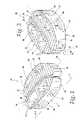
- FIG. 1is a perspective view from above and one end of an interbody implant embodying the present invention
- FIG. 2is a perspective view similar to FIG. 1 of the interbody implant, but taken from a different angle;
- FIG. 3is an exploded perspective view of the interbody implant of FIGS. 1 and 2 , again from above and taken from a different angle;
- FIG. 4is an exploded perspective view of the interbody implant of FIGS. 1-3 , taken from the opposite end with the implant flipped over to show its underside and at a different angle than FIG. 3 ;
- FIG. 5is a plan view of the interbody implant of FIGS. 1-4 ;
- FIG. 6is a side elevation taken from line 6 - 6 in FIG. 1 ;
- FIGS. 7-12are a series of plan views illustrating the method of inserting the interbody implant into a disc space embodying the invention.
- FIG. 13is a plan view showing the interbody implant in its installed state in a disc space
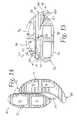
- FIG. 14is a plan view similar to that of FIG. 5 , but showing another embodiment of the interbody implant.
- FIG. 15is a rotated, mid-line cross section showing the implant of FIG. 14 in an assembled state.
- an interbody implant 20is shown and includes first and second members 22 and 24 that are configured to allow the members 22 and 24 to be inserted into a disc space separately and then connected together in the disc space to form the interbody implant 20 .
- Thisallows for a larger interbody implant 20 because the combined size of the members 22 and 24 can exceed the size of an access opening into the disc space, with each of the members 22 and 24 being sized to pass separately through the access opening before being connected together in the disc space.
- retention of the interbody implant 20 in its desired location/orientation in the disc spaceis believed to be improved over what otherwise could be obtained if the members 22 and 24 were inserted but not connected to each other.
- the implant 20in the connected state, has a pair of vertebra engaging faces 26 and 28 spaced from each other by an implant height H, opposite sides 30 and 32 extending between the faces 26 and 28 and spaced from each other by an implant width W, and opposite ends 34 and 36 extending between the faces 26 and 28 and spaced from each other by an implant length L parallel to a longitudinal axis 40 .
- the sides 30 and 32 and ends 34 and 36define a perimeter 38 for the implant 20 that is generally curved and without sharp corners.
- FIG. 5the sides 30 and 32 and ends 34 and 36 define a perimeter 38 for the implant 20 that is generally curved and without sharp corners.
- the implant height Hbe tapered along the axis 40 so that the height H is greater in the middle of the implant 20 than at the ends 34 and 36 .
- the each of the faces 26 and 28have a convex radius of curvature R. While this taper is preferred, in some procedures it may be desirable for there to be no such taper in the implant 20 , with the faces 26 and 28 lying in parallel planes to each other over the length L.
- serrations, ridges, or protrusions 41be provided in each of the faces 26 and 28 to enhance retention of the implant in its desired location/orientation, i.e. to prevent backout.
- serrations, ridges, or protrusions 41be provided in each of the faces 26 and 28 to enhance retention of the implant in its desired location/orientation, i.e. to prevent backout.
- there to be no protrusionsit may be desirable for there to be no protrusions.
- the members 22 and 24each have a laterally facing connection portion 42 and 44 , respectively, with the connection portion 42 being located between a pair of oppositely facing vertebra contact surfaces 46 and 48 , and the connection portion 44 being located between a pair of oppositely facing vertebra contact surfaces 50 and 52 .
- the surfaces 46 and 50are aligned with each other to define the face 26
- the surfaces 48 and 52are aligned with each other to define the face 28 .
- each of the surfaces 46 , 48 , 50 , and 52have the convex radius of curvature R and the protrusions 41 .
- connection portion 42includes a cylindrically shaped protrusion or rib 56 having an outwardly facing cylindrical surface 58 and the connection portion 44 includes a cylindrically shaped slot 60 having an inwardly facing cylindrical surface 62 , with both the rib 56 and the slot or groove 60 being centered on the axis 40 in the connected state.
- the rib 56extends from a planar side surface 64 and the groove 60 is formed in a planar side surface 66 .
- the cylindrical surfaces 58 and 62conform to each other.
- cylindrical surfaces 58 and 62are shown, there are many other possible mating cross-sectional shapes for the rib 56 and groove 60 that can provide a suitable connection between the members 22 and 24 , such as, for example, mating dovetail shapes or mating T shapes.
- the implantis preferably configured for use with an insertion tool 70 , best seen in FIGS. 7-12 , having a longitudinal axis 72 .
- the member 22include an attachment portion 74 that is configured to releasably fix the first member 22 to the insertion tool 70 , and for the member 24 to include a guide portion 76 for sliding engagement of with the insertion tool 70 for movement along the axis 72 relative to the insertion tool 70 .
- the attachment portion 74includes a threaded bore 78 centered in the rib 56 and extending along the axis 40 to engage a threaded end 80 of the insertion tool 70
- the guide portion 76includes a cylindrical bore 82 extending along the axis 40 and becomes part of the groove 60 .
- the bore 82be formed in a nose portion 84 of the member 24 that extends laterally past the plane of the surface 66 so that the material of the member 24 completely surrounds the insertion tool 70 over a length of the guide portion 74 .
- the nose portion 84may be eliminated, with the bore 82 having an open portion over its entire length.
- the bore 82has a smaller diameter than the cylindrical surface 62 of the groove 60 , which results in an annular shoulder 86 located between the bore 82 and the surface 60 , as best seen in FIG. 3 .
- the annular shoulder 86abuts an end surface 88 of the rib 56 in the connected state to prevent further relative motion between the members 22 and 24 along the axis 40 in the direction of engagement for the connection portions 42 and 44 .
- the implant 20may be used in minimally invasive surgery/less invasive surgery (MIS/LIS) procedures such as percutaneous transforaminal lumbar interbody fusion (TLIF), posterior lumbar interbody fusion (PLIF), or in non-MIS procedures, as desired, and as persons of ordinary skill in the art who have the benefit of the description of the invention understand. While the implant 20 can be used with any surgical procedure, it is particularly suited for use with MIS Procedures. MIS procedures seek to reduce cutting, bleeding, and tissue damage or disturbance associated with implanting a spinal implant in a patient's body.
- a port 90may be inserted into a patient to provide access to vertebrae that are to be fused together.
- Instrumentse.g., distractors, chisels, and implant inserters
- a discectomymay be performed to remove disc material and form a first disc space between two adjacent vertebral bodies.
- a distractormay be positioned between to establish a separation distance in the disc space between the vertebrae.
- a chiselmay be used to remove portions of vertebral bone and form channels in the vertebral end plates adjacent the disc space. Removing bone portions may promote bone growth that couples an implant inserted in the disc space to the vertebrae. Osteophytes may also be removed to make insertion of the implant easier.
- FIGS. 7-13sequentially illustrate one possible MIS procedure for implanting the implant 20 into a patient.
- FIG. 7shows the member 22 attached to the insertion tool 70 by the attachment portion 74 and inserted into a prepared disc space 92 through the port 90 and an access opening 94 to the disc space 92 .
- the access opening 94 to the disc space 92will typically have a size that essentially corresponds to an interior diameter of the port 90 .
- FIG. 8shows the next step of the procedure where the member 22 is shifted or translated to one side of the disc space 92 using the insertion tool 90 , as indicated by the arrow A. This shift allows for the next step of the procedure shown in FIG.
- connection portions 42 and 44are engaged to form the implant 20 by sliding the member 24 along the insertion tool 70 while the member 22 is held in place by the tool 70 . While not shown, it may be desirable to utilize another tool to slide the member 24 along the tool 70 for the steps of the procedure shown in FIGS. 9-12 . Finally, as illustrated in FIG.
- the insertion tool 70is disengaged from the attachment portion 74 and withdrawn from the port 90 , which is also removed after any further procedures are completed, such as, for example, inserting packing material, such as cancellous bone, synthetic bone, or other bone graft material, in the disc space 92 around the implant 20 .
- the implant 20 and the described insertion methodcan be used with any type of approach, including posterior, anterior, and lateral.
- insertion tool 70is shown in the form of a cylindrical rod, shapes other than cylindrical are possible. Furthermore, it should be understood that other forms of insertion tools 70 are also possible.
- the interbody implant 20can be used to promote bone fusion and/or establish a desired separation distance between adjacent vertebrae.
- the implant 20may have surfaces made of bone or bone growth promoting material (e.g., hydroxyapatite or titanium plasma spray) that promotes fusion of the implants to vertebrae.
- the implant 20may include passages or openings 96 .
- the openings 96may have any desired cross-sectional shape.
- the passage cross-sectional shapemay be, but is not limited to, circular, oval, square, rectangular, or irregular.
- the openings 96may be packed with bone graft or other bone growth material (e.g., autogenic bone graft, allogenic bone graft, xenogenic bone graft, or synthetic bone graft) that promotes bone growth from vertebrae into the implant 20 to fuse the implant 20 to the vertebrae.
- bone graft or other bone growth materiale.g., autogenic bone graft, allogenic bone graft, xenogenic bone graft, or synthetic bone graft
- connection portions 42 and 44it is believed that the pressure of the vertebral bodies on the implant 20 will typically be sufficient to retain the members 22 and 24 in the connected state.
- a threaded fastenercould be provided extending through the bore 82 to engage the threaded bore 78 to retain the connection portions 42 and 44 in engagement.
- some form of a “snap connection”could be provided between members 22 and 24 to retain the connection portions 42 and 44 in engagement.
- one possible form of a “snap connection” or “snap lock” 98is shown in FIGS.
- the members 22 and 24 of the implant 20have been modified so that the member 22 includes a somewhat hook-shaped latch 100 extending in cantilevered fashion from one end thereof, and the member 24 includes an opening 102 formed in the nose portion 84 , which has been extended in comparison to the embodiment of FIGS. 1-13 , with a somewhat wedge-shaped catch 104 formed in the opening 102 to engage the latch 100 as the members 22 and 24 are moved into engagement along the axis 40 and retain the first and second members 22 and 24 in the assembled state, as best seen in FIG. 15 . While a preferred form is shown in FIGS. 14 and 15 , it will be appreciated by those skilled in the art that there are many possible forms for the latch 100 and catch 104 .
- the latch 100could have been formed extending from the nose 84 of the member 24 , with the opening 102 and catch 104 formed in the end of the member 22 .
- Implants 20may be constructed of biocompatible material sufficiently strong to maintain bone separation, and may be made of bone or of other material, such as metals, ceramics, polymers, or combinations thereof.
- Bone used to form an implantmay be allogenic bone or xenogenic bone.
- a portion or portions of the implant 20may be autogenic bone.
- bone, or portions of bone, used to form the implant 20may be demineralized. Portions of the bone used to form the implant 20 may be cortical bone. The cortical bone may provide strength to the implant 20 .
- the bone used to form an implant 20may be processed in a frozen state.
- bone used to form the implant 20may be processed in a freeze-dried state.
- the implant 20 and/or outer surfaces of the implant 20 that contact a vertebramay be made of a material other than bone.
- the surfaces that contacts the vertebramay be treated to enhance osseointegration of the implant with the vertebra.
- the surfacesmay include protrusions that extend into the vertebra.
- the surfacemay include a hydroxyapatite coating, a titanium plasma spray coating, and/or texturing. Texturing may be used to modify the surface of an implant to reduce expulsion and provide stability. Texturing may be provided by many different methods, such as, but not limited to, sanding the surface, forming grooves within the surface, shot peening the surface, scoring the surface using an electrical discharge process, and/or embedding hard particles within the surface. Texturing may also be formed in outer surfaces of implants formed of bone.
- An implant, or a portion of an implantmay be made of a bioabsorbable material.
- portions of an implantmay be made of a polyanhydride, an alpha polyester, and/or a polylactic acid-polyglycolic acid copolymer.
- the implant 20may be constructed from bar stock or formed from moldable material of suitable strength to withstand pressure within a normal human spine.
- the implant 20may be constructed from metals including, but not limited to, titanium, titanium alloys, and medical grade stainless steel.
- the implant 20may be molded or cut from materials including, but not limited to, polyether ether ketone (PEEK), carbon fiber reinforced PEEK, and other polymers.
- the implant 20may be processed so that posterior side or end, as implanted in a patient, of the implant 20 has a different height H than anterior side or end of the implant 20 .
- Other dimensional characteristics of an implant 20may also be adjusted to produce an implant having a desired geometry.
Landscapes
- Health & Medical Sciences (AREA)
- Engineering & Computer Science (AREA)
- Biomedical Technology (AREA)
- Orthopedic Medicine & Surgery (AREA)
- Transplantation (AREA)
- Neurology (AREA)
- Oral & Maxillofacial Surgery (AREA)
- Cardiology (AREA)
- Heart & Thoracic Surgery (AREA)
- Vascular Medicine (AREA)
- Life Sciences & Earth Sciences (AREA)
- Animal Behavior & Ethology (AREA)
- General Health & Medical Sciences (AREA)
- Public Health (AREA)
- Veterinary Medicine (AREA)
- Physical Education & Sports Medicine (AREA)
- Prostheses (AREA)
Abstract
Description
Claims (23)
Priority Applications (2)
| Application Number | Priority Date | Filing Date | Title |
|---|---|---|---|
| US11/697,108US8163026B2 (en) | 2007-04-05 | 2007-04-05 | Interbody implant |
| US13/397,154US8603177B2 (en) | 2007-04-05 | 2012-02-15 | Interbody implant |
Applications Claiming Priority (1)
| Application Number | Priority Date | Filing Date | Title |
|---|---|---|---|
| US11/697,108US8163026B2 (en) | 2007-04-05 | 2007-04-05 | Interbody implant |
Related Child Applications (1)
| Application Number | Title | Priority Date | Filing Date |
|---|---|---|---|
| US13/397,154ContinuationUS8603177B2 (en) | 2007-04-05 | 2012-02-15 | Interbody implant |
Publications (2)
| Publication Number | Publication Date |
|---|---|
| US20080249622A1 US20080249622A1 (en) | 2008-10-09 |
| US8163026B2true US8163026B2 (en) | 2012-04-24 |
Family
ID=39827653
Family Applications (2)
| Application Number | Title | Priority Date | Filing Date |
|---|---|---|---|
| US11/697,108Expired - Fee RelatedUS8163026B2 (en) | 2007-04-05 | 2007-04-05 | Interbody implant |
| US13/397,154Active2027-04-08US8603177B2 (en) | 2007-04-05 | 2012-02-15 | Interbody implant |
Family Applications After (1)
| Application Number | Title | Priority Date | Filing Date |
|---|---|---|---|
| US13/397,154Active2027-04-08US8603177B2 (en) | 2007-04-05 | 2012-02-15 | Interbody implant |
Country Status (1)
| Country | Link |
|---|---|
| US (2) | US8163026B2 (en) |
Cited By (19)
| Publication number | Priority date | Publication date | Assignee | Title |
|---|---|---|---|---|
| US8845728B1 (en)* | 2011-09-23 | 2014-09-30 | Samy Abdou | Spinal fixation devices and methods of use |
| USD731061S1 (en) | 2012-11-28 | 2015-06-02 | Nuvasive, Inc. | Intervertebral implant |
| US9198765B1 (en) | 2011-10-31 | 2015-12-01 | Nuvasive, Inc. | Expandable spinal fusion implants and related methods |
| US9408717B2 (en) | 2013-10-08 | 2016-08-09 | Pioneer Surgical Technology, Inc. | Expandable intervertebral device, and systems and methods for inserting same |
| US9445918B1 (en) | 2012-10-22 | 2016-09-20 | Nuvasive, Inc. | Expandable spinal fusion implants and related instruments and methods |
| US9468536B1 (en) | 2011-11-02 | 2016-10-18 | Nuvasive, Inc. | Spinal fusion implants and related methods |
| US9700430B2 (en) | 2013-03-15 | 2017-07-11 | Pioneer Surgical Technology, Inc. | Systems and methods for inserting an expandable intervertebral device |
| US9700425B1 (en) | 2011-03-20 | 2017-07-11 | Nuvasive, Inc. | Vertebral body replacement and insertion methods |
| US10111757B2 (en) | 2012-10-22 | 2018-10-30 | Cogent Spine, LLC | Devices and methods for spinal stabilization and instrumentation |
| US10543107B2 (en) | 2009-12-07 | 2020-01-28 | Samy Abdou | Devices and methods for minimally invasive spinal stabilization and instrumentation |
| US10548740B1 (en) | 2016-10-25 | 2020-02-04 | Samy Abdou | Devices and methods for vertebral bone realignment |
| US10695105B2 (en) | 2012-08-28 | 2020-06-30 | Samy Abdou | Spinal fixation devices and methods of use |
| US10857003B1 (en) | 2015-10-14 | 2020-12-08 | Samy Abdou | Devices and methods for vertebral stabilization |
| USD907771S1 (en) | 2017-10-09 | 2021-01-12 | Pioneer Surgical Technology, Inc. | Intervertebral implant |
| US10918498B2 (en) | 2004-11-24 | 2021-02-16 | Samy Abdou | Devices and methods for inter-vertebral orthopedic device placement |
| US10973648B1 (en) | 2016-10-25 | 2021-04-13 | Samy Abdou | Devices and methods for vertebral bone realignment |
| US11006982B2 (en) | 2012-02-22 | 2021-05-18 | Samy Abdou | Spinous process fixation devices and methods of use |
| US11147682B2 (en) | 2017-09-08 | 2021-10-19 | Pioneer Surgical Technology, Inc. | Intervertebral implants, instruments, and methods |
| US11179248B2 (en) | 2018-10-02 | 2021-11-23 | Samy Abdou | Devices and methods for spinal implantation |
Families Citing this family (100)
| Publication number | Priority date | Publication date | Assignee | Title |
|---|---|---|---|---|
| AR038680A1 (en) | 2002-02-19 | 2005-01-26 | Synthes Ag | INTERVERTEBRAL IMPLANT |
| US6793678B2 (en) | 2002-06-27 | 2004-09-21 | Depuy Acromed, Inc. | Prosthetic intervertebral motion disc having dampening |
| CA2515247C (en) | 2003-02-06 | 2010-10-05 | Synthes (U.S.A.) | Intervertebral implant |
| AU2004212942A1 (en) | 2003-02-14 | 2004-09-02 | Depuy Spine, Inc. | In-situ formed intervertebral fusion device |
| US20040267367A1 (en) | 2003-06-30 | 2004-12-30 | Depuy Acromed, Inc | Intervertebral implant with conformable endplate |
| US8636802B2 (en) | 2004-03-06 | 2014-01-28 | DePuy Synthes Products, LLC | Dynamized interspinal implant |
| US8241330B2 (en) | 2007-01-11 | 2012-08-14 | Lanx, Inc. | Spinous process implants and associated methods |
| US9055981B2 (en) | 2004-10-25 | 2015-06-16 | Lanx, Inc. | Spinal implants and methods |
| US8758442B2 (en) | 2005-05-06 | 2014-06-24 | Titan Spine, Llc | Composite implants having integration surfaces composed of a regular repeating pattern |
| US9125756B2 (en) | 2005-05-06 | 2015-09-08 | Titan Spine, Llc | Processes for producing regular repeating patterns on surfaces of interbody devices |
| US8814939B2 (en) | 2005-05-06 | 2014-08-26 | Titan Spine, Llc | Implants having three distinct surfaces |
| US8992622B2 (en) | 2005-05-06 | 2015-03-31 | Titan Spine, Llc | Interbody spinal implant having a roughened surface topography |
| US8591590B2 (en) | 2005-05-06 | 2013-11-26 | Titan Spine, Llc | Spinal implant having a transverse aperture |
| US8585765B2 (en) | 2005-05-06 | 2013-11-19 | Titan Spine, Llc | Endplate-preserving spinal implant having a raised expulsion-resistant edge |
| US8562684B2 (en) | 2005-05-06 | 2013-10-22 | Titan Spine, Llc | Endplate-preserving spinal implant with an integration plate having a roughened surface topography |
| US8758443B2 (en) | 2005-05-06 | 2014-06-24 | Titan Spine, Llc | Implants with integration surfaces having regular repeating surface patterns |
| US8585766B2 (en) | 2005-05-06 | 2013-11-19 | Titan Spine, Llc | Endplate-preserving spinal implant with an integration plate having durable connectors |
| US8617248B2 (en) | 2005-05-06 | 2013-12-31 | Titan Spine, Llc | Spinal implant having variable ratios of the integration surface area to the axial passage area |
| US9168147B2 (en) | 2005-05-06 | 2015-10-27 | Titan Spine, Llc | Self-deploying locking screw retention device |
| US8551176B2 (en) | 2005-05-06 | 2013-10-08 | Titan Spine, Llc | Spinal implant having a passage for enhancing contact between bone graft material and cortical endplate bone |
| US11096796B2 (en) | 2005-05-06 | 2021-08-24 | Titan Spine, Llc | Interbody spinal implant having a roughened surface topography on one or more internal surfaces |
| US8562685B2 (en) | 2005-05-06 | 2013-10-22 | Titan Spine, Llc | Spinal implant and integration plate for optimizing vertebral endplate contact load-bearing edges |
| US8585767B2 (en) | 2005-05-06 | 2013-11-19 | Titan Spine, Llc | Endplate-preserving spinal implant with an integration plate having durable connectors |
| US8262737B2 (en) | 2005-05-06 | 2012-09-11 | Titan Spine, Llc | Composite interbody spinal implant having openings of predetermined size and shape |
| US8623088B1 (en)* | 2005-07-15 | 2014-01-07 | Nuvasive, Inc. | Spinal fusion implant and related methods |
| US8500778B2 (en)* | 2006-02-01 | 2013-08-06 | DePuy Synthes Products, LLC | Interspinous process spacer |
| EP1988855A2 (en) | 2006-02-27 | 2008-11-12 | Synthes GmbH | Intervertebral implant with fixation geometry |
| US20080000857A1 (en)* | 2006-06-13 | 2008-01-03 | Wonderland Nurserygoods Co., Ltd. | Modular organizer for crib or playpen |
| USD741488S1 (en) | 2006-07-17 | 2015-10-20 | Nuvasive, Inc. | Spinal fusion implant |
| US9737414B2 (en) | 2006-11-21 | 2017-08-22 | Vertebral Technologies, Inc. | Methods and apparatus for minimally invasive modular interbody fusion devices |
| WO2008070863A2 (en) | 2006-12-07 | 2008-06-12 | Interventional Spine, Inc. | Intervertebral implant |
| US9265532B2 (en) | 2007-01-11 | 2016-02-23 | Lanx, Inc. | Interspinous implants and methods |
| US9247968B2 (en) | 2007-01-11 | 2016-02-02 | Lanx, Inc. | Spinous process implants and associated methods |
| US8900307B2 (en)* | 2007-06-26 | 2014-12-02 | DePuy Synthes Products, LLC | Highly lordosed fusion cage |
| US20090093882A1 (en)* | 2007-10-09 | 2009-04-09 | Oh Younghoon | Sliding interbody device |
| JP2011502708A (en) | 2007-11-16 | 2011-01-27 | ジンテス ゲゼルシャフト ミット ベシュレンクテル ハフツング | Low profile intervertebral implant |
| EP2237748B1 (en) | 2008-01-17 | 2012-09-05 | Synthes GmbH | An expandable intervertebral implant |
| US8936641B2 (en) | 2008-04-05 | 2015-01-20 | DePuy Synthes Products, LLC | Expandable intervertebral implant |
| US8147554B2 (en)* | 2008-10-13 | 2012-04-03 | Globus Medical, Inc. | Intervertebral spacer |
| CN102256570B (en) | 2008-11-07 | 2015-09-02 | 斯恩蒂斯有限公司 | Spacer and connecting plate assembly between vertebral bodies |
| US9526620B2 (en) | 2009-03-30 | 2016-12-27 | DePuy Synthes Products, Inc. | Zero profile spinal fusion cage |
| US8241364B2 (en)* | 2009-04-02 | 2012-08-14 | Globus Medical, Inc. | Method of installation of intervertebral spacers |
| KR101687435B1 (en) | 2009-07-06 | 2016-12-19 | 신세스 게엠바하 | Expandable fixation assemblies |
| US9393129B2 (en) | 2009-12-10 | 2016-07-19 | DePuy Synthes Products, Inc. | Bellows-like expandable interbody fusion cage |
| EP2547292B1 (en) | 2010-03-16 | 2019-04-24 | Pinnacle Spine Group, LLC | Ntervertebral implants and graft delivery systems |
| FR2958151B1 (en)* | 2010-04-06 | 2012-04-27 | Hassan Razian | SYSTEM FOR REPLACING AN INTERVERTEBRAL DISC. |
| US8956414B2 (en) | 2010-04-21 | 2015-02-17 | Spinecraft, LLC | Intervertebral body implant, instrument and method |
| US9907560B2 (en) | 2010-06-24 | 2018-03-06 | DePuy Synthes Products, Inc. | Flexible vertebral body shavers |
| US8979860B2 (en) | 2010-06-24 | 2015-03-17 | DePuy Synthes Products. LLC | Enhanced cage insertion device |
| US8623091B2 (en) | 2010-06-29 | 2014-01-07 | DePuy Synthes Products, LLC | Distractible intervertebral implant |
| US9241810B1 (en)* | 2010-07-12 | 2016-01-26 | Spinesmith Partners, L.P. | Fusion device and associated methods |
| US20120078372A1 (en) | 2010-09-23 | 2012-03-29 | Thomas Gamache | Novel implant inserter having a laterally-extending dovetail engagement feature |
| US8858637B2 (en)* | 2010-09-30 | 2014-10-14 | Stryker Spine | Surgical implant with guiding rail |
| US9402732B2 (en) | 2010-10-11 | 2016-08-02 | DePuy Synthes Products, Inc. | Expandable interspinous process spacer implant |
| WO2012088238A2 (en) | 2010-12-21 | 2012-06-28 | Synthes Usa, Llc | Intervertebral implants, systems, and methods of use |
| US8961606B2 (en)* | 2011-09-16 | 2015-02-24 | Globus Medical, Inc. | Multi-piece intervertebral implants |
| US9539109B2 (en) | 2011-09-16 | 2017-01-10 | Globus Medical, Inc. | Low profile plate |
| US9398960B2 (en) | 2011-09-16 | 2016-07-26 | Globus Medical, Inc. | Multi-piece intervertebral implants |
| US9204975B2 (en) | 2011-09-16 | 2015-12-08 | Globus Medical, Inc. | Multi-piece intervertebral implants |
| US9248028B2 (en) | 2011-09-16 | 2016-02-02 | DePuy Synthes Products, Inc. | Removable, bone-securing cover plate for intervertebral fusion cage |
| US11812923B2 (en) | 2011-10-07 | 2023-11-14 | Alan Villavicencio | Spinal fixation device |
| US8992619B2 (en) | 2011-11-01 | 2015-03-31 | Titan Spine, Llc | Microstructured implant surfaces |
| US9380932B1 (en) | 2011-11-02 | 2016-07-05 | Pinnacle Spine Group, Llc | Retractor devices for minimally invasive access to the spine |
| US9510953B2 (en)* | 2012-03-16 | 2016-12-06 | Vertebral Technologies, Inc. | Modular segmented disc nucleus implant |
| CA2880825C (en) | 2012-03-20 | 2021-03-16 | Titan Spine, Llc | Friction-fit spinal endplate and endplate-preserving method |
| US9283089B2 (en)* | 2012-04-05 | 2016-03-15 | Warsaw Orthopedic, Inc. | Interbody bone implant device |
| US9795492B1 (en)* | 2012-04-30 | 2017-10-24 | Nuvasive, Inc. | Magnetically connectable interbody spinal implant devices |
| US9770341B1 (en)* | 2012-04-30 | 2017-09-26 | Nuvasive, Inc. | Magnetic spinal implant |
| US10709482B2 (en)* | 2012-05-30 | 2020-07-14 | Globus Medical, Inc. | Laminoplasty system |
| EP2877127B1 (en) | 2012-07-26 | 2019-08-21 | Synthes GmbH | Expandable implant |
| EP2716261A1 (en) | 2012-10-02 | 2014-04-09 | Titan Spine, LLC | Implants with self-deploying anchors |
| US9498349B2 (en) | 2012-10-09 | 2016-11-22 | Titan Spine, Llc | Expandable spinal implant with expansion wedge and anchor |
| US9717601B2 (en) | 2013-02-28 | 2017-08-01 | DePuy Synthes Products, Inc. | Expandable intervertebral implant, system, kit and method |
| US9522070B2 (en) | 2013-03-07 | 2016-12-20 | Interventional Spine, Inc. | Intervertebral implant |
| WO2014159739A1 (en) | 2013-03-14 | 2014-10-02 | Pinnacle Spine Group, Llc | Interbody implants and graft delivery systems |
| US9937052B2 (en) | 2013-03-15 | 2018-04-10 | Cogent Spine Llc | Methods and apparatus for implanting an interbody device |
| US9345589B2 (en)* | 2013-12-19 | 2016-05-24 | Ilion Medical, Inc. | Bone implants for orthopedic procedures and corresponding methods |
| US9615935B2 (en) | 2014-01-30 | 2017-04-11 | Titan Spine, Llc | Thermally activated shape memory spring assemblies for implant expansion |
| US9867718B2 (en)* | 2014-10-22 | 2018-01-16 | DePuy Synthes Products, Inc. | Intervertebral implants, systems, and methods of use |
| US11426290B2 (en) | 2015-03-06 | 2022-08-30 | DePuy Synthes Products, Inc. | Expandable intervertebral implant, system, kit and method |
| US10624757B2 (en) | 2015-04-09 | 2020-04-21 | Centinel Spine, Llc | Spinal implants configured for tissue sparing angle of insertion and related methods |
| US9913727B2 (en) | 2015-07-02 | 2018-03-13 | Medos International Sarl | Expandable implant |
| US11510788B2 (en) | 2016-06-28 | 2022-11-29 | Eit Emerging Implant Technologies Gmbh | Expandable, angularly adjustable intervertebral cages |
| EP3474784A2 (en) | 2016-06-28 | 2019-05-01 | Eit Emerging Implant Technologies GmbH | Expandable and angularly adjustable intervertebral cages with articulating joint |
| US10537436B2 (en) | 2016-11-01 | 2020-01-21 | DePuy Synthes Products, Inc. | Curved expandable cage |
| FR3058316B1 (en)* | 2016-11-09 | 2021-09-24 | Lape Medical | SET INCLUDING TWO INTERSOMATIC IMPLANTS |
| US10888433B2 (en) | 2016-12-14 | 2021-01-12 | DePuy Synthes Products, Inc. | Intervertebral implant inserter and related methods |
| US10398563B2 (en) | 2017-05-08 | 2019-09-03 | Medos International Sarl | Expandable cage |
| US11344424B2 (en) | 2017-06-14 | 2022-05-31 | Medos International Sarl | Expandable intervertebral implant and related methods |
| US10940016B2 (en) | 2017-07-05 | 2021-03-09 | Medos International Sarl | Expandable intervertebral fusion cage |
| US11278422B2 (en)* | 2017-07-19 | 2022-03-22 | Vasudeva Rao Rajakumar Deshpande | Intervertebral spinal cage implant and method of assembling the same |
| US10973658B2 (en) | 2017-11-27 | 2021-04-13 | Titan Spine, Inc. | Rotating implant and associated instrumentation |
| CN108125736A (en)* | 2018-02-09 | 2018-06-08 | 申才良 | A kind of spliced homogeneous allogenic bone fusion device |
| US11135070B2 (en) | 2018-02-14 | 2021-10-05 | Titan Spine, Inc. | Modular adjustable corpectomy cage |
| US11446156B2 (en) | 2018-10-25 | 2022-09-20 | Medos International Sarl | Expandable intervertebral implant, inserter instrument, and related methods |
| CN109498221B (en)* | 2018-12-28 | 2021-06-18 | 宁波华科润生物科技有限公司 | Assembled vertebral body fusion system for entering way through minimally invasive access |
| US11426286B2 (en) | 2020-03-06 | 2022-08-30 | Eit Emerging Implant Technologies Gmbh | Expandable intervertebral implant |
| US11850160B2 (en) | 2021-03-26 | 2023-12-26 | Medos International Sarl | Expandable lordotic intervertebral fusion cage |
| US11752009B2 (en) | 2021-04-06 | 2023-09-12 | Medos International Sarl | Expandable intervertebral fusion cage |
| US12090064B2 (en) | 2022-03-01 | 2024-09-17 | Medos International Sarl | Stabilization members for expandable intervertebral implants, and related systems and methods |
Citations (18)
| Publication number | Priority date | Publication date | Assignee | Title |
|---|---|---|---|---|
| US5397364A (en) | 1993-10-12 | 1995-03-14 | Danek Medical, Inc. | Anterior interbody fusion device |
| US5545229A (en) | 1988-08-18 | 1996-08-13 | University Of Medicine And Dentistry Of Nj | Functional and biocompatible intervertebral disc spacer containing elastomeric material of varying hardness |
| US5899941A (en) | 1997-12-09 | 1999-05-04 | Chubu Bearing Kabushiki Kaisha | Artificial intervertebral disk |
| US6387130B1 (en) | 1999-04-16 | 2002-05-14 | Nuvasive, Inc. | Segmented linked intervertebral implant systems |
| US20030125739A1 (en) | 2001-12-12 | 2003-07-03 | Bagga Charanpreet S. | Bioactive spinal implants and method of manufacture thereof |
| US20030139812A1 (en) | 2001-11-09 | 2003-07-24 | Javier Garcia | Spinal implant |
| US6648916B1 (en)* | 1997-12-10 | 2003-11-18 | Sdgi Holdings, Inc. | Osteogenic fusion device |
| US20050033435A1 (en) | 2003-08-04 | 2005-02-10 | Spine Next | Intervertebral disk prosthesis |
| US20050107881A1 (en) | 2003-05-02 | 2005-05-19 | Neville Alleyne | Artificial spinal disk |
| US20050222683A1 (en) | 2004-03-31 | 2005-10-06 | Sdgi Holdings | Shape memory alloy disc replacement device |
| US20060058807A1 (en) | 2004-08-25 | 2006-03-16 | Michael Landry | Expandable interbody fusion device |
| WO2006051547A2 (en) | 2004-11-15 | 2006-05-18 | Disc-O-Tech Medical Technologies, Ltd. | Assembled prosthesis such as a disc |
| US7070621B2 (en)* | 1999-04-07 | 2006-07-04 | Howmedica Osteonics Corp. | Low profile fusion cage and insertion set |
| US20060173542A1 (en) | 2004-12-28 | 2006-08-03 | Takiron Co., Ltd. | Biomaterial for artificial cartilage |
| US20060259144A1 (en) | 2004-01-27 | 2006-11-16 | Warsaw Orthopedic Inc. | Hybrid intervertebral disc system |
| US20080119853A1 (en) | 2006-11-21 | 2008-05-22 | Jeffrey Felt | Methods and apparatus for minimally invasive modular interbody fusion devices |
| US7534265B1 (en)* | 1999-01-11 | 2009-05-19 | Warsaw Orthopedic, Inc. | Intervertebral spacers with side wall accessible interior cavity |
| US7591853B2 (en) | 2005-03-09 | 2009-09-22 | Vertebral Technologies, Inc. | Rail-based modular disc nucleus prosthesis |
- 2007
- 2007-04-05USUS11/697,108patent/US8163026B2/ennot_activeExpired - Fee Related
- 2012
- 2012-02-15USUS13/397,154patent/US8603177B2/enactiveActive
Patent Citations (22)
| Publication number | Priority date | Publication date | Assignee | Title |
|---|---|---|---|---|
| US5545229A (en) | 1988-08-18 | 1996-08-13 | University Of Medicine And Dentistry Of Nj | Functional and biocompatible intervertebral disc spacer containing elastomeric material of varying hardness |
| US5397364A (en) | 1993-10-12 | 1995-03-14 | Danek Medical, Inc. | Anterior interbody fusion device |
| US5899941A (en) | 1997-12-09 | 1999-05-04 | Chubu Bearing Kabushiki Kaisha | Artificial intervertebral disk |
| US7763079B2 (en)* | 1997-12-10 | 2010-07-27 | Warsaw Orthopedic, Inc. | Osteogenic fusion device |
| US6648916B1 (en)* | 1997-12-10 | 2003-11-18 | Sdgi Holdings, Inc. | Osteogenic fusion device |
| US7534265B1 (en)* | 1999-01-11 | 2009-05-19 | Warsaw Orthopedic, Inc. | Intervertebral spacers with side wall accessible interior cavity |
| US7070621B2 (en)* | 1999-04-07 | 2006-07-04 | Howmedica Osteonics Corp. | Low profile fusion cage and insertion set |
| US6387130B1 (en) | 1999-04-16 | 2002-05-14 | Nuvasive, Inc. | Segmented linked intervertebral implant systems |
| US20030139812A1 (en) | 2001-11-09 | 2003-07-24 | Javier Garcia | Spinal implant |
| US20030125739A1 (en) | 2001-12-12 | 2003-07-03 | Bagga Charanpreet S. | Bioactive spinal implants and method of manufacture thereof |
| US20050107881A1 (en) | 2003-05-02 | 2005-05-19 | Neville Alleyne | Artificial spinal disk |
| US20050033435A1 (en) | 2003-08-04 | 2005-02-10 | Spine Next | Intervertebral disk prosthesis |
| US20060259144A1 (en) | 2004-01-27 | 2006-11-16 | Warsaw Orthopedic Inc. | Hybrid intervertebral disc system |
| US20050222683A1 (en) | 2004-03-31 | 2005-10-06 | Sdgi Holdings | Shape memory alloy disc replacement device |
| US20060058807A1 (en) | 2004-08-25 | 2006-03-16 | Michael Landry | Expandable interbody fusion device |
| US20080133017A1 (en) | 2004-11-15 | 2008-06-05 | Disc-O- Tech Medical Technology | Assembled Prosthesis Such as a Disc |
| WO2006051547A2 (en) | 2004-11-15 | 2006-05-18 | Disc-O-Tech Medical Technologies, Ltd. | Assembled prosthesis such as a disc |
| US20060173542A1 (en) | 2004-12-28 | 2006-08-03 | Takiron Co., Ltd. | Biomaterial for artificial cartilage |
| US7591853B2 (en) | 2005-03-09 | 2009-09-22 | Vertebral Technologies, Inc. | Rail-based modular disc nucleus prosthesis |
| US20090276047A1 (en) | 2005-03-09 | 2009-11-05 | Felt Jeffrey C | Rail-based modular disc prosthesis |
| US20100057144A1 (en) | 2005-03-09 | 2010-03-04 | Felt Jeffrey C | Rail-based modular disc nucleus prosthesis |
| US20080119853A1 (en) | 2006-11-21 | 2008-05-22 | Jeffrey Felt | Methods and apparatus for minimally invasive modular interbody fusion devices |
Cited By (55)
| Publication number | Priority date | Publication date | Assignee | Title |
|---|---|---|---|---|
| US11992423B2 (en) | 2004-11-24 | 2024-05-28 | Samy Abdou | Devices and methods for inter-vertebral orthopedic device placement |
| US11096799B2 (en) | 2004-11-24 | 2021-08-24 | Samy Abdou | Devices and methods for inter-vertebral orthopedic device placement |
| US10918498B2 (en) | 2004-11-24 | 2021-02-16 | Samy Abdou | Devices and methods for inter-vertebral orthopedic device placement |
| US11918486B2 (en) | 2009-12-07 | 2024-03-05 | Samy Abdou | Devices and methods for minimally invasive spinal stabilization and instrumentation |
| US10945861B2 (en) | 2009-12-07 | 2021-03-16 | Samy Abdou | Devices and methods for minimally invasive spinal stabilization and instrumentation |
| US10857004B2 (en) | 2009-12-07 | 2020-12-08 | Samy Abdou | Devices and methods for minimally invasive spinal stabilization and instrumentation |
| US10610380B2 (en) | 2009-12-07 | 2020-04-07 | Samy Abdou | Devices and methods for minimally invasive spinal stabilization and instrumentation |
| US10543107B2 (en) | 2009-12-07 | 2020-01-28 | Samy Abdou | Devices and methods for minimally invasive spinal stabilization and instrumentation |
| US10485672B2 (en) | 2011-03-20 | 2019-11-26 | Nuvasive, Inc. | Vertebral body replacement and insertion methods |
| US12186198B2 (en) | 2011-03-20 | 2025-01-07 | Nuvasive, Inc. | Vertebral body replacement and insertion methods |
| US11389301B2 (en) | 2011-03-20 | 2022-07-19 | Nuvasive, Inc. | Vertebral body replacement and insertion methods |
| US9700425B1 (en) | 2011-03-20 | 2017-07-11 | Nuvasive, Inc. | Vertebral body replacement and insertion methods |
| US11324608B2 (en) | 2011-09-23 | 2022-05-10 | Samy Abdou | Spinal fixation devices and methods of use |
| US11517449B2 (en) | 2011-09-23 | 2022-12-06 | Samy Abdou | Spinal fixation devices and methods of use |
| US9610176B1 (en) | 2011-09-23 | 2017-04-04 | Samy Abdou | Spinal fixation devices and methods of use |
| US12167973B2 (en) | 2011-09-23 | 2024-12-17 | Samy Abdou | Spinal fixation devices and methods of use |
| US9901458B1 (en) | 2011-09-23 | 2018-02-27 | Samy Abdou | Spinal fixation devices and methods of use |
| US9867714B1 (en)* | 2011-09-23 | 2018-01-16 | Samy Abdou | Spinal fixation devices and methods of use |
| US9314350B1 (en) | 2011-09-23 | 2016-04-19 | Samy Abdou | Spinal fixation devices and methods of use |
| US8845728B1 (en)* | 2011-09-23 | 2014-09-30 | Samy Abdou | Spinal fixation devices and methods of use |
| US10575961B1 (en) | 2011-09-23 | 2020-03-03 | Samy Abdou | Spinal fixation devices and methods of use |
| US9655744B1 (en) | 2011-10-31 | 2017-05-23 | Nuvasive, Inc. | Expandable spinal fusion implants and related methods |
| US9198765B1 (en) | 2011-10-31 | 2015-12-01 | Nuvasive, Inc. | Expandable spinal fusion implants and related methods |
| US9468536B1 (en) | 2011-11-02 | 2016-10-18 | Nuvasive, Inc. | Spinal fusion implants and related methods |
| US10098753B1 (en) | 2011-11-02 | 2018-10-16 | Nuvasive, Inc. | Spinal fusion implants and related methods |
| US11839413B2 (en) | 2012-02-22 | 2023-12-12 | Samy Abdou | Spinous process fixation devices and methods of use |
| US11006982B2 (en) | 2012-02-22 | 2021-05-18 | Samy Abdou | Spinous process fixation devices and methods of use |
| US10695105B2 (en) | 2012-08-28 | 2020-06-30 | Samy Abdou | Spinal fixation devices and methods of use |
| US11559336B2 (en) | 2012-08-28 | 2023-01-24 | Samy Abdou | Spinal fixation devices and methods of use |
| US9445918B1 (en) | 2012-10-22 | 2016-09-20 | Nuvasive, Inc. | Expandable spinal fusion implants and related instruments and methods |
| US11399954B2 (en) | 2012-10-22 | 2022-08-02 | Nuvasive, Inc. | Expandable spinal fusion implant, related instruments and methods |
| US12048635B2 (en) | 2012-10-22 | 2024-07-30 | Nuvasive, Inc. | Expandable spinal fusion implant, related instruments and methods |
| US10350084B1 (en) | 2012-10-22 | 2019-07-16 | Nuvasive, Inc. | Expandable spinal fusion implant, related instruments and methods |
| US11918483B2 (en) | 2012-10-22 | 2024-03-05 | Cogent Spine Llc | Devices and methods for spinal stabilization and instrumentation |
| US10111757B2 (en) | 2012-10-22 | 2018-10-30 | Cogent Spine, LLC | Devices and methods for spinal stabilization and instrumentation |
| US11173040B2 (en) | 2012-10-22 | 2021-11-16 | Cogent Spine, LLC | Devices and methods for spinal stabilization and instrumentation |
| USD731061S1 (en) | 2012-11-28 | 2015-06-02 | Nuvasive, Inc. | Intervertebral implant |
| US11696838B2 (en) | 2013-03-15 | 2023-07-11 | Pioneer Surgical Technology, Inc. | Systems and methods for inserting an expandable intervertebral device |
| US10779956B2 (en) | 2013-03-15 | 2020-09-22 | Pioneer Surgical Technology, Inc. | Systems and methods for inserting an expandable intervertebral device |
| US9700430B2 (en) | 2013-03-15 | 2017-07-11 | Pioneer Surgical Technology, Inc. | Systems and methods for inserting an expandable intervertebral device |
| US9687359B2 (en) | 2013-10-08 | 2017-06-27 | Pioneer Surgical Technology, Inc. | Expandable intervertebral device, and systems and methods for inserting same |
| US9408717B2 (en) | 2013-10-08 | 2016-08-09 | Pioneer Surgical Technology, Inc. | Expandable intervertebral device, and systems and methods for inserting same |
| US11246718B2 (en) | 2015-10-14 | 2022-02-15 | Samy Abdou | Devices and methods for vertebral stabilization |
| US10857003B1 (en) | 2015-10-14 | 2020-12-08 | Samy Abdou | Devices and methods for vertebral stabilization |
| US10744000B1 (en) | 2016-10-25 | 2020-08-18 | Samy Abdou | Devices and methods for vertebral bone realignment |
| US10973648B1 (en) | 2016-10-25 | 2021-04-13 | Samy Abdou | Devices and methods for vertebral bone realignment |
| US11752008B1 (en) | 2016-10-25 | 2023-09-12 | Samy Abdou | Devices and methods for vertebral bone realignment |
| US10548740B1 (en) | 2016-10-25 | 2020-02-04 | Samy Abdou | Devices and methods for vertebral bone realignment |
| US11259935B1 (en) | 2016-10-25 | 2022-03-01 | Samy Abdou | Devices and methods for vertebral bone realignment |
| US11058548B1 (en) | 2016-10-25 | 2021-07-13 | Samy Abdou | Devices and methods for vertebral bone realignment |
| US11147682B2 (en) | 2017-09-08 | 2021-10-19 | Pioneer Surgical Technology, Inc. | Intervertebral implants, instruments, and methods |
| US12279965B2 (en) | 2017-09-08 | 2025-04-22 | Xtant Medical Holdings, Inc. | Intervertebral implants, instruments, and methods |
| USD968613S1 (en) | 2017-10-09 | 2022-11-01 | Pioneer Surgical Technology, Inc. | Intervertebral implant |
| USD907771S1 (en) | 2017-10-09 | 2021-01-12 | Pioneer Surgical Technology, Inc. | Intervertebral implant |
| US11179248B2 (en) | 2018-10-02 | 2021-11-23 | Samy Abdou | Devices and methods for spinal implantation |
Also Published As
| Publication number | Publication date |
|---|---|
| US20080249622A1 (en) | 2008-10-09 |
| US8603177B2 (en) | 2013-12-10 |
| US20120150302A1 (en) | 2012-06-14 |
Similar Documents
| Publication | Publication Date | Title |
|---|---|---|
| US8163026B2 (en) | Interbody implant | |
| US10898339B2 (en) | Spinal surgical implant and related methods | |
| USRE46647E1 (en) | Intervertebral implant for transforaminal posterior lumbar interbody fusion procedure | |
| US8128700B2 (en) | Allograft intervertebral implant and method of manufacturing the same | |
| EP1383449B1 (en) | Intervertebral implant for transforaminal posterior lumbar interbody fusion procedure | |
| US8221502B2 (en) | Expandable spinal implant | |
| US8685105B2 (en) | Systems and methods for spinal fusion | |
| US20100286780A1 (en) | Expandable spinal fusion cage and associated instrumentation | |
| US20010049560A1 (en) | Intervertebral allograft spacer | |
| US20130178940A1 (en) | Expandable cage spinal implant | |
| CN101198299A (en) | Expandable Spinal Implants and Related Placement Procedures |
Legal Events
| Date | Code | Title | Description |
|---|---|---|---|
| AS | Assignment | Owner name:ABBOTT LABORATORIES, ILLINOIS Free format text:ASSIGNMENT OF ASSIGNORS INTEREST;ASSIGNOR:GRAY, WAYNE P.;REEL/FRAME:019537/0954 Effective date:20070405 | |
| AS | Assignment | Owner name:ABBOTT SPINE INC., TEXAS Free format text:ASSIGNMENT OF ASSIGNORS INTEREST;ASSIGNOR:GRAY, WAYNE P.;REEL/FRAME:021875/0475 Effective date:20070405 | |
| AS | Assignment | Owner name:ZIMMER SPINE AUSTIN, INC., TEXAS Free format text:CHANGE OF NAME;ASSIGNOR:ABBOTT SPINE INC.;REEL/FRAME:023335/0086 Effective date:20081215 | |
| AS | Assignment | Owner name:ZIMMER SPINE, INC., MINNESOTA Free format text:MERGER;ASSIGNOR:ZIMMER SPINE AUSTIN, INC.;REEL/FRAME:023336/0927 Effective date:20090828 | |
| STCF | Information on status: patent grant | Free format text:PATENTED CASE | |
| FPAY | Fee payment | Year of fee payment:4 | |
| MAFP | Maintenance fee payment | Free format text:PAYMENT OF MAINTENANCE FEE, 8TH YEAR, LARGE ENTITY (ORIGINAL EVENT CODE: M1552); ENTITY STATUS OF PATENT OWNER: LARGE ENTITY Year of fee payment:8 | |
| AS | Assignment | Owner name:ZIMMER BIOMET SPINE, INC., INDIANA Free format text:MERGER;ASSIGNOR:ZIMMER SPINE, INC.;REEL/FRAME:059232/0356 Effective date:20160930 | |
| AS | Assignment | Owner name:JPMORGAN CHASE BANK, N.A., AS ADMINISTRATIVE AGENT, NEW YORK Free format text:SECURITY INTEREST;ASSIGNORS:BIOMET 3I, LLC;EBI, LLC;ZIMMER BIOMET SPINE, INC.;AND OTHERS;REEL/FRAME:059293/0213 Effective date:20220228 | |
| FEPP | Fee payment procedure | Free format text:MAINTENANCE FEE REMINDER MAILED (ORIGINAL EVENT CODE: REM.); ENTITY STATUS OF PATENT OWNER: LARGE ENTITY | |
| AS | Assignment | Owner name:CERBERUS BUSINESS FINANCE AGENCY, LLC, NEW YORK Free format text:GRANT OF A SECURITY INTEREST -- PATENTS;ASSIGNORS:ZIMMER BIOMET SPINE, LLC;EBI, LLC;REEL/FRAME:066970/0806 Effective date:20240401 | |
| AS | Assignment | Owner name:ZIMMER BIOMET SPINE, LLC (F/K/A ZIMMER BIOMET SPINE, INC.), COLORADO Free format text:RELEASE BY SECURED PARTY;ASSIGNOR:JPMORGAN CHASE BANK, N.A.;REEL/FRAME:066973/0833 Effective date:20240401 Owner name:EBI, LLC, NEW JERSEY Free format text:RELEASE BY SECURED PARTY;ASSIGNOR:JPMORGAN CHASE BANK, N.A.;REEL/FRAME:066973/0833 Effective date:20240401 | |
| LAPS | Lapse for failure to pay maintenance fees | Free format text:PATENT EXPIRED FOR FAILURE TO PAY MAINTENANCE FEES (ORIGINAL EVENT CODE: EXP.); ENTITY STATUS OF PATENT OWNER: LARGE ENTITY | |
| STCH | Information on status: patent discontinuation | Free format text:PATENT EXPIRED DUE TO NONPAYMENT OF MAINTENANCE FEES UNDER 37 CFR 1.362 | |
| FP | Lapsed due to failure to pay maintenance fee | Effective date:20240424 | |
| AS | Assignment | Owner name:ZIMMER BIOMET SPINE, LLC, COLORADO Free format text:CHANGE OF NAME;ASSIGNOR:ZIMMER BIOMET SPINE, INC.;REEL/FRAME:069772/0121 Effective date:20240220 Owner name:HIGHRIDGE MEDICAL, LLC, COLORADO Free format text:CHANGE OF NAME;ASSIGNOR:ZIMMER BIOMET SPINE, LLC;REEL/FRAME:069772/0248 Effective date:20240405 |