US8162970B2 - Vascular filter - Google Patents
Vascular filterDownload PDFInfo
- Publication number
- US8162970B2 US8162970B2US11/822,680US82268007AUS8162970B2US 8162970 B2US8162970 B2US 8162970B2US 82268007 AUS82268007 AUS 82268007AUS 8162970 B2US8162970 B2US 8162970B2
- Authority
- US
- United States
- Prior art keywords
- filter
- vascular filter
- capture
- members
- support portion
- Prior art date
- Legal status (The legal status is an assumption and is not a legal conclusion. Google has not performed a legal analysis and makes no representation as to the accuracy of the status listed.)
- Active, expires
Links
- 230000002792vascularEffects0.000titleclaimsdescription166
- 208000007536ThrombosisDiseases0.000claimsabstractdescription36
- 210000004204blood vesselAnatomy0.000claimsdescription52
- 239000000463materialSubstances0.000claimsdescription38
- 238000005538encapsulationMethods0.000claimsdescription4
- 210000001631vena cava inferiorAnatomy0.000abstractdescription94
- 208000010378Pulmonary EmbolismDiseases0.000abstractdescription32
- 210000004072lungAnatomy0.000abstractdescription8
- 238000013461designMethods0.000description22
- 230000017531blood circulationEffects0.000description15
- 208000005189EmbolismDiseases0.000description13
- 238000000034methodMethods0.000description12
- HLXZNVUGXRDIFK-UHFFFAOYSA-Nnickel titaniumChemical compound[Ti].[Ti].[Ti].[Ti].[Ti].[Ti].[Ti].[Ti].[Ti].[Ti].[Ti].[Ni].[Ni].[Ni].[Ni].[Ni].[Ni].[Ni].[Ni].[Ni].[Ni].[Ni].[Ni].[Ni].[Ni]HLXZNVUGXRDIFK-UHFFFAOYSA-N0.000description12
- 229910001000nickel titaniumInorganic materials0.000description12
- 229920000642polymerPolymers0.000description11
- 229910052751metalInorganic materials0.000description10
- 206010051055Deep vein thrombosisDiseases0.000description8
- 206010047249Venous thrombosisDiseases0.000description8
- 239000002184metalSubstances0.000description8
- JJTUDXZGHPGLLC-IMJSIDKUSA-N4511-42-6Chemical compoundC[C@@H]1OC(=O)[C@H](C)OC1=OJJTUDXZGHPGLLC-IMJSIDKUSA-N0.000description7
- 238000001914filtrationMethods0.000description7
- 239000000178monomerSubstances0.000description7
- 210000003462veinAnatomy0.000description7
- 238000013459approachMethods0.000description6
- 239000007943implantSubstances0.000description6
- 230000007774longtermEffects0.000description6
- 238000013508migrationMethods0.000description6
- 230000005012migrationEffects0.000description6
- 230000008901benefitEffects0.000description5
- 238000002513implantationMethods0.000description5
- 230000010100anticoagulationEffects0.000description4
- 230000009286beneficial effectEffects0.000description4
- 239000003814drugSubstances0.000description4
- 229940079593drugDrugs0.000description4
- 210000003191femoral veinAnatomy0.000description4
- 210000003141lower extremityAnatomy0.000description4
- 238000002560therapeutic procedureMethods0.000description4
- 230000015556catabolic processEffects0.000description3
- 238000005520cutting processMethods0.000description3
- 239000007857degradation productSubstances0.000description3
- 230000002685pulmonary effectEffects0.000description3
- 206010014522Embolism venousDiseases0.000description2
- 208000032843HemorrhageDiseases0.000description2
- 229920000331PolyhydroxybutyratePolymers0.000description2
- 238000004873anchoringMethods0.000description2
- 208000034158bleedingDiseases0.000description2
- 230000000740bleeding effectEffects0.000description2
- 239000008280bloodSubstances0.000description2
- 210000004369bloodAnatomy0.000description2
- 238000005266castingMethods0.000description2
- 235000019994cavaNutrition0.000description2
- 239000011248coating agentSubstances0.000description2
- 238000000576coating methodMethods0.000description2
- 238000002591computed tomographyMethods0.000description2
- 230000034994deathEffects0.000description2
- 231100000517deathToxicity0.000description2
- 238000006731degradation reactionMethods0.000description2
- 238000003745diagnosisMethods0.000description2
- 230000003511endothelial effectEffects0.000description2
- 238000005516engineering processMethods0.000description2
- 230000003628erosive effectEffects0.000description2
- 238000003384imaging methodMethods0.000description2
- 238000003780insertionMethods0.000description2
- 230000037431insertionEffects0.000description2
- 210000004731jugular veinAnatomy0.000description2
- 239000003550markerSubstances0.000description2
- 238000002483medicationMethods0.000description2
- 239000002245particleSubstances0.000description2
- 210000004197pelvisAnatomy0.000description2
- 239000005015poly(hydroxybutyrate)Substances0.000description2
- 230000002265preventionEffects0.000description2
- 230000008569processEffects0.000description2
- 230000001737promoting effectEffects0.000description2
- 230000000452restraining effectEffects0.000description2
- 230000000717retained effectEffects0.000description2
- 210000005245right atriumAnatomy0.000description2
- 239000012781shape memory materialSubstances0.000description2
- 229910001220stainless steelInorganic materials0.000description2
- 239000010935stainless steelSubstances0.000description2
- 238000001356surgical procedureMethods0.000description2
- 238000011282treatmentMethods0.000description2
- 238000002604ultrasonographyMethods0.000description2
- 208000004043venous thromboembolismDiseases0.000description2
- 238000012276Endovascular treatmentMethods0.000description1
- 208000034826Genetic Predisposition to DiseaseDiseases0.000description1
- 206010028980NeoplasmDiseases0.000description1
- 208000001435ThromboembolismDiseases0.000description1
- RTAQQCXQSZGOHL-UHFFFAOYSA-NTitaniumChemical compound[Ti]RTAQQCXQSZGOHL-UHFFFAOYSA-N0.000description1
- 210000001015abdomenAnatomy0.000description1
- 230000001154acute effectEffects0.000description1
- 239000000853adhesiveSubstances0.000description1
- 230000001070adhesive effectEffects0.000description1
- 210000003484anatomyAnatomy0.000description1
- 238000002583angiographyMethods0.000description1
- 210000001367arteryAnatomy0.000description1
- 230000002146bilateral effectEffects0.000description1
- 238000006065biodegradation reactionMethods0.000description1
- 201000011510cancerDiseases0.000description1
- 238000006243chemical reactionMethods0.000description1
- 238000012790confirmationMethods0.000description1
- 238000010276constructionMethods0.000description1
- 229920001577copolymerPolymers0.000description1
- 230000007423decreaseEffects0.000description1
- 230000008021depositionEffects0.000description1
- 238000002059diagnostic imagingMethods0.000description1
- 238000007598dipping methodMethods0.000description1
- 201000010099diseaseDiseases0.000description1
- 208000037265diseases, disorders, signs and symptomsDiseases0.000description1
- 230000002526effect on cardiovascular systemEffects0.000description1
- 230000000694effectsEffects0.000description1
- 238000013156embolectomyMethods0.000description1
- 239000000262estrogenSubstances0.000description1
- 238000001704evaporationMethods0.000description1
- 230000008020evaporationEffects0.000description1
- 238000000605extractionMethods0.000description1
- 210000003414extremityAnatomy0.000description1
- 239000000945fillerSubstances0.000description1
- 238000002594fluoroscopyMethods0.000description1
- 230000006870functionEffects0.000description1
- 210000003111iliac veinAnatomy0.000description1
- 238000011065in-situ storageMethods0.000description1
- 238000013152interventional procedureMethods0.000description1
- 230000007794irritationEffects0.000description1
- JJTUDXZGHPGLLC-UHFFFAOYSA-NlactideChemical compoundCC1OC(=O)C(C)OC1=OJJTUDXZGHPGLLC-UHFFFAOYSA-N0.000description1
- 230000002934lysing effectEffects0.000description1
- 230000036210malignancyEffects0.000description1
- 239000007769metal materialSubstances0.000description1
- 150000002739metalsChemical class0.000description1
- 238000009206nuclear medicineMethods0.000description1
- 210000000056organAnatomy0.000description1
- 230000007310pathophysiologyEffects0.000description1
- 230000002093peripheral effectEffects0.000description1
- 229920002463poly(p-dioxanone) polymerPolymers0.000description1
- 229920001610polycaprolactonePolymers0.000description1
- 239000004632polycaprolactoneSubstances0.000description1
- 229920006254polymer filmPolymers0.000description1
- 230000035935pregnancyEffects0.000description1
- 239000000047productSubstances0.000description1
- 230000002035prolonged effectEffects0.000description1
- 230000000069prophylactic effectEffects0.000description1
- 238000011321prophylaxisMethods0.000description1
- 238000002588pulmonary angiographyMethods0.000description1
- 230000000306recurrent effectEffects0.000description1
- 230000004044responseEffects0.000description1
- 229910000679solderInorganic materials0.000description1
- 239000002904solventSubstances0.000description1
- 229920001169thermoplasticPolymers0.000description1
- 239000010936titaniumSubstances0.000description1
- 229910052719titaniumInorganic materials0.000description1
- 210000001364upper extremityAnatomy0.000description1
- 210000005166vasculatureAnatomy0.000description1
- PAPBSGBWRJIAAV-UHFFFAOYSA-Nε-CaprolactoneChemical compoundO=C1CCCCCO1PAPBSGBWRJIAAV-UHFFFAOYSA-N0.000description1
Images


Classifications
- B—PERFORMING OPERATIONS; TRANSPORTING
- B01—PHYSICAL OR CHEMICAL PROCESSES OR APPARATUS IN GENERAL
- B01D—SEPARATION
- B01D61/00—Processes of separation using semi-permeable membranes, e.g. dialysis, osmosis or ultrafiltration; Apparatus, accessories or auxiliary operations specially adapted therefor
- A—HUMAN NECESSITIES
- A61—MEDICAL OR VETERINARY SCIENCE; HYGIENE
- A61F—FILTERS IMPLANTABLE INTO BLOOD VESSELS; PROSTHESES; DEVICES PROVIDING PATENCY TO, OR PREVENTING COLLAPSING OF, TUBULAR STRUCTURES OF THE BODY, e.g. STENTS; ORTHOPAEDIC, NURSING OR CONTRACEPTIVE DEVICES; FOMENTATION; TREATMENT OR PROTECTION OF EYES OR EARS; BANDAGES, DRESSINGS OR ABSORBENT PADS; FIRST-AID KITS
- A61F2/00—Filters implantable into blood vessels; Prostheses, i.e. artificial substitutes or replacements for parts of the body; Appliances for connecting them with the body; Devices providing patency to, or preventing collapsing of, tubular structures of the body, e.g. stents
- A61F2/01—Filters implantable into blood vessels
- A61F2/0103—With centering means
- A—HUMAN NECESSITIES
- A61—MEDICAL OR VETERINARY SCIENCE; HYGIENE
- A61F—FILTERS IMPLANTABLE INTO BLOOD VESSELS; PROSTHESES; DEVICES PROVIDING PATENCY TO, OR PREVENTING COLLAPSING OF, TUBULAR STRUCTURES OF THE BODY, e.g. STENTS; ORTHOPAEDIC, NURSING OR CONTRACEPTIVE DEVICES; FOMENTATION; TREATMENT OR PROTECTION OF EYES OR EARS; BANDAGES, DRESSINGS OR ABSORBENT PADS; FIRST-AID KITS
- A61F2/00—Filters implantable into blood vessels; Prostheses, i.e. artificial substitutes or replacements for parts of the body; Appliances for connecting them with the body; Devices providing patency to, or preventing collapsing of, tubular structures of the body, e.g. stents
- A61F2/01—Filters implantable into blood vessels
- A61F2/0105—Open ended, i.e. legs gathered only at one side
- A—HUMAN NECESSITIES
- A61—MEDICAL OR VETERINARY SCIENCE; HYGIENE
- A61F—FILTERS IMPLANTABLE INTO BLOOD VESSELS; PROSTHESES; DEVICES PROVIDING PATENCY TO, OR PREVENTING COLLAPSING OF, TUBULAR STRUCTURES OF THE BODY, e.g. STENTS; ORTHOPAEDIC, NURSING OR CONTRACEPTIVE DEVICES; FOMENTATION; TREATMENT OR PROTECTION OF EYES OR EARS; BANDAGES, DRESSINGS OR ABSORBENT PADS; FIRST-AID KITS
- A61F2/00—Filters implantable into blood vessels; Prostheses, i.e. artificial substitutes or replacements for parts of the body; Appliances for connecting them with the body; Devices providing patency to, or preventing collapsing of, tubular structures of the body, e.g. stents
- A61F2/01—Filters implantable into blood vessels
- A61F2/011—Instruments for their placement or removal
- A—HUMAN NECESSITIES
- A61—MEDICAL OR VETERINARY SCIENCE; HYGIENE
- A61F—FILTERS IMPLANTABLE INTO BLOOD VESSELS; PROSTHESES; DEVICES PROVIDING PATENCY TO, OR PREVENTING COLLAPSING OF, TUBULAR STRUCTURES OF THE BODY, e.g. STENTS; ORTHOPAEDIC, NURSING OR CONTRACEPTIVE DEVICES; FOMENTATION; TREATMENT OR PROTECTION OF EYES OR EARS; BANDAGES, DRESSINGS OR ABSORBENT PADS; FIRST-AID KITS
- A61F2/00—Filters implantable into blood vessels; Prostheses, i.e. artificial substitutes or replacements for parts of the body; Appliances for connecting them with the body; Devices providing patency to, or preventing collapsing of, tubular structures of the body, e.g. stents
- A61F2/82—Devices providing patency to, or preventing collapsing of, tubular structures of the body, e.g. stents
- A61F2/86—Stents in a form characterised by the wire-like elements; Stents in the form characterised by a net-like or mesh-like structure
- A—HUMAN NECESSITIES
- A61—MEDICAL OR VETERINARY SCIENCE; HYGIENE
- A61F—FILTERS IMPLANTABLE INTO BLOOD VESSELS; PROSTHESES; DEVICES PROVIDING PATENCY TO, OR PREVENTING COLLAPSING OF, TUBULAR STRUCTURES OF THE BODY, e.g. STENTS; ORTHOPAEDIC, NURSING OR CONTRACEPTIVE DEVICES; FOMENTATION; TREATMENT OR PROTECTION OF EYES OR EARS; BANDAGES, DRESSINGS OR ABSORBENT PADS; FIRST-AID KITS
- A61F2/00—Filters implantable into blood vessels; Prostheses, i.e. artificial substitutes or replacements for parts of the body; Appliances for connecting them with the body; Devices providing patency to, or preventing collapsing of, tubular structures of the body, e.g. stents
- A61F2/01—Filters implantable into blood vessels
- A61F2002/016—Filters implantable into blood vessels made from wire-like elements
- A—HUMAN NECESSITIES
- A61—MEDICAL OR VETERINARY SCIENCE; HYGIENE
- A61F—FILTERS IMPLANTABLE INTO BLOOD VESSELS; PROSTHESES; DEVICES PROVIDING PATENCY TO, OR PREVENTING COLLAPSING OF, TUBULAR STRUCTURES OF THE BODY, e.g. STENTS; ORTHOPAEDIC, NURSING OR CONTRACEPTIVE DEVICES; FOMENTATION; TREATMENT OR PROTECTION OF EYES OR EARS; BANDAGES, DRESSINGS OR ABSORBENT PADS; FIRST-AID KITS
- A61F2210/00—Particular material properties of prostheses classified in groups A61F2/00 - A61F2/26 or A61F2/82 or A61F9/00 or A61F11/00 or subgroups thereof
- A61F2210/0004—Particular material properties of prostheses classified in groups A61F2/00 - A61F2/26 or A61F2/82 or A61F9/00 or A61F11/00 or subgroups thereof bioabsorbable
- A—HUMAN NECESSITIES
- A61—MEDICAL OR VETERINARY SCIENCE; HYGIENE
- A61F—FILTERS IMPLANTABLE INTO BLOOD VESSELS; PROSTHESES; DEVICES PROVIDING PATENCY TO, OR PREVENTING COLLAPSING OF, TUBULAR STRUCTURES OF THE BODY, e.g. STENTS; ORTHOPAEDIC, NURSING OR CONTRACEPTIVE DEVICES; FOMENTATION; TREATMENT OR PROTECTION OF EYES OR EARS; BANDAGES, DRESSINGS OR ABSORBENT PADS; FIRST-AID KITS
- A61F2230/00—Geometry of prostheses classified in groups A61F2/00 - A61F2/26 or A61F2/82 or A61F9/00 or A61F11/00 or subgroups thereof
- A61F2230/0002—Two-dimensional shapes, e.g. cross-sections
- A61F2230/0004—Rounded shapes, e.g. with rounded corners
- A61F2230/0006—Rounded shapes, e.g. with rounded corners circular
- A—HUMAN NECESSITIES
- A61—MEDICAL OR VETERINARY SCIENCE; HYGIENE
- A61F—FILTERS IMPLANTABLE INTO BLOOD VESSELS; PROSTHESES; DEVICES PROVIDING PATENCY TO, OR PREVENTING COLLAPSING OF, TUBULAR STRUCTURES OF THE BODY, e.g. STENTS; ORTHOPAEDIC, NURSING OR CONTRACEPTIVE DEVICES; FOMENTATION; TREATMENT OR PROTECTION OF EYES OR EARS; BANDAGES, DRESSINGS OR ABSORBENT PADS; FIRST-AID KITS
- A61F2230/00—Geometry of prostheses classified in groups A61F2/00 - A61F2/26 or A61F2/82 or A61F9/00 or A61F11/00 or subgroups thereof
- A61F2230/0002—Two-dimensional shapes, e.g. cross-sections
- A61F2230/0017—Angular shapes
- A61F2230/0021—Angular shapes square
- A—HUMAN NECESSITIES
- A61—MEDICAL OR VETERINARY SCIENCE; HYGIENE
- A61F—FILTERS IMPLANTABLE INTO BLOOD VESSELS; PROSTHESES; DEVICES PROVIDING PATENCY TO, OR PREVENTING COLLAPSING OF, TUBULAR STRUCTURES OF THE BODY, e.g. STENTS; ORTHOPAEDIC, NURSING OR CONTRACEPTIVE DEVICES; FOMENTATION; TREATMENT OR PROTECTION OF EYES OR EARS; BANDAGES, DRESSINGS OR ABSORBENT PADS; FIRST-AID KITS
- A61F2230/00—Geometry of prostheses classified in groups A61F2/00 - A61F2/26 or A61F2/82 or A61F9/00 or A61F11/00 or subgroups thereof
- A61F2230/0002—Two-dimensional shapes, e.g. cross-sections
- A61F2230/0028—Shapes in the form of latin or greek characters
- A61F2230/005—Rosette-shaped, e.g. star-shaped
- A—HUMAN NECESSITIES
- A61—MEDICAL OR VETERINARY SCIENCE; HYGIENE
- A61F—FILTERS IMPLANTABLE INTO BLOOD VESSELS; PROSTHESES; DEVICES PROVIDING PATENCY TO, OR PREVENTING COLLAPSING OF, TUBULAR STRUCTURES OF THE BODY, e.g. STENTS; ORTHOPAEDIC, NURSING OR CONTRACEPTIVE DEVICES; FOMENTATION; TREATMENT OR PROTECTION OF EYES OR EARS; BANDAGES, DRESSINGS OR ABSORBENT PADS; FIRST-AID KITS
- A61F2230/00—Geometry of prostheses classified in groups A61F2/00 - A61F2/26 or A61F2/82 or A61F9/00 or A61F11/00 or subgroups thereof
- A61F2230/0002—Two-dimensional shapes, e.g. cross-sections
- A61F2230/0028—Shapes in the form of latin or greek characters
- A61F2230/0058—X-shaped
- A—HUMAN NECESSITIES
- A61—MEDICAL OR VETERINARY SCIENCE; HYGIENE
- A61F—FILTERS IMPLANTABLE INTO BLOOD VESSELS; PROSTHESES; DEVICES PROVIDING PATENCY TO, OR PREVENTING COLLAPSING OF, TUBULAR STRUCTURES OF THE BODY, e.g. STENTS; ORTHOPAEDIC, NURSING OR CONTRACEPTIVE DEVICES; FOMENTATION; TREATMENT OR PROTECTION OF EYES OR EARS; BANDAGES, DRESSINGS OR ABSORBENT PADS; FIRST-AID KITS
- A61F2230/00—Geometry of prostheses classified in groups A61F2/00 - A61F2/26 or A61F2/82 or A61F9/00 or A61F11/00 or subgroups thereof
- A61F2230/0063—Three-dimensional shapes
- A61F2230/0067—Three-dimensional shapes conical
- A—HUMAN NECESSITIES
- A61—MEDICAL OR VETERINARY SCIENCE; HYGIENE
- A61F—FILTERS IMPLANTABLE INTO BLOOD VESSELS; PROSTHESES; DEVICES PROVIDING PATENCY TO, OR PREVENTING COLLAPSING OF, TUBULAR STRUCTURES OF THE BODY, e.g. STENTS; ORTHOPAEDIC, NURSING OR CONTRACEPTIVE DEVICES; FOMENTATION; TREATMENT OR PROTECTION OF EYES OR EARS; BANDAGES, DRESSINGS OR ABSORBENT PADS; FIRST-AID KITS
- A61F2230/00—Geometry of prostheses classified in groups A61F2/00 - A61F2/26 or A61F2/82 or A61F9/00 or A61F11/00 or subgroups thereof
- A61F2230/0063—Three-dimensional shapes
- A61F2230/0069—Three-dimensional shapes cylindrical
- A—HUMAN NECESSITIES
- A61—MEDICAL OR VETERINARY SCIENCE; HYGIENE
- A61F—FILTERS IMPLANTABLE INTO BLOOD VESSELS; PROSTHESES; DEVICES PROVIDING PATENCY TO, OR PREVENTING COLLAPSING OF, TUBULAR STRUCTURES OF THE BODY, e.g. STENTS; ORTHOPAEDIC, NURSING OR CONTRACEPTIVE DEVICES; FOMENTATION; TREATMENT OR PROTECTION OF EYES OR EARS; BANDAGES, DRESSINGS OR ABSORBENT PADS; FIRST-AID KITS
- A61F2230/00—Geometry of prostheses classified in groups A61F2/00 - A61F2/26 or A61F2/82 or A61F9/00 or A61F11/00 or subgroups thereof
- A61F2230/0063—Three-dimensional shapes
- A61F2230/0073—Quadric-shaped
- A61F2230/008—Quadric-shaped paraboloidal
- A—HUMAN NECESSITIES
- A61—MEDICAL OR VETERINARY SCIENCE; HYGIENE
- A61F—FILTERS IMPLANTABLE INTO BLOOD VESSELS; PROSTHESES; DEVICES PROVIDING PATENCY TO, OR PREVENTING COLLAPSING OF, TUBULAR STRUCTURES OF THE BODY, e.g. STENTS; ORTHOPAEDIC, NURSING OR CONTRACEPTIVE DEVICES; FOMENTATION; TREATMENT OR PROTECTION OF EYES OR EARS; BANDAGES, DRESSINGS OR ABSORBENT PADS; FIRST-AID KITS
- A61F2230/00—Geometry of prostheses classified in groups A61F2/00 - A61F2/26 or A61F2/82 or A61F9/00 or A61F11/00 or subgroups thereof
- A61F2230/0063—Three-dimensional shapes
- A61F2230/0091—Three-dimensional shapes helically-coiled or spirally-coiled, i.e. having a 2-D spiral cross-section
Definitions
- This inventionrelates to a vascular filter.
- this inventionrelates to an inferior vena cava filter.
- vena cava filterin the vena cava to prevent thrombus entering the right atrium. They have been in use clinically for a number of years. The use of filters implanted in the inferior vena cava is for the prevention of pulmonary embolism in high-risk patients.
- Deep vein thrombosis (DVT) and pulmonary embolism (PE)are common medical conditions that contribute substantially to individual patient morbidity and mortality as well as global healthcare costs.
- DVTdevelops within the deep veins of the lower extremities but also can involve or arise solely from the veins of the pelvis or the upper extremities.
- PEpulmonary embolism
- PEpulmonary embolism
- DVT and PECommon clinical risk factors for DVT and PE include age older than 50 years, prolonged immobilization because of illness, travel or surgery, oestrogen therapy, pregnancy and malignancy among others. A genetic predisposition has also been suggested.
- Candidates for inferior vena cava (IVC) filter placementare typically evaluated for the presence of lower-extremity DVT and/or PE.
- Imaging methods used to document the presence of lower-extremity DVTinclude ultra sound and peripheral venography.
- PEcan also be diagnosed by using nuclear medicine ventilation-perfusion scans.
- CTcomputed tomography
- MRAMagnetic resonance angiography
- IVCinferior vena cava
- the inferior vena cavais the largest venous structure in the body. It drains the venous return from the lower extremities, pelvis, and abdomen into the right atrium. Before filter placement, an inferior vena cavogram is obtained to assess caval diameter and patency, the extent of thrombus and to understand the presence of any venous anomalies.
- Filterscan be placed by either a femoral or jugular approach.
- the basic principle for femoral insertionis to choose the side that has patent and preferably thrombus-free veins.
- Right femoral punctureis preferable because there is less angulation in the iliac veins.
- a careful left femoral approachmay be successful if a right-sided puncture is contraindicated.
- a jugular approachcan be used when there is inferior vena cava or bilateral iliofemoral thrombosis.
- the common femoral veinis punctured, while for the jugular approach, the puncture site is at the internal jugular vein.
- Another inferior vena cavogramis performed after filter placement to check the position and stability of the filter.
- This inventionis aimed towards providing an improved vascular filter.
- vascular filtercomprising:—
- the filterBy capturing the thrombus, the filter prevents the thrombus from passing to the heart or lungs, which may cause pulmonaryembolism.
- the support memberis configured to extend circumferentially around a wall of a blood vessel.
- the support membermay extend circumferentially in a wave pattern.
- the support membermay extend circumferentially in a zigzag pattern.
- the support membermay extend circumferentially in a crown pattern.
- the support membermay extend circumferentially in a sinusoid pattern.
- the wave/sinusoid pattern of the support memberfacilitates collapse of the support member for ease of delivery and/or retrieval through the blood vessel.
- the support membermay be configured to extend longitudinally along a wall of a blood vessel. A distal end of the support member may be located distally of a distal end of the capture member.
- a proximal end of the support membermay be located proximally of a proximal end of the capture member.
- the filtermay comprise a first support member configured to extend circumferentially around a wall of a blood vessel, a second support member configured to extend circumferentially around the wall of the blood vessel, and a third support member configured to extend longitudinally along the wall of the blood vessel.
- the third support membermay connect the first support member to the second support member.
- the first support member, the second support member and the third support membermay be formed integrally.
- the first support membermay be provided at the proximal end of the filter.
- the second support membermay be provided at the distal end of the filter.
- the support membercomprises a body portion and one or more openings in the body portion.
- the openings in the support memberfacilitate tissue ingrowth.
- a drug coatingmay be added to the structure to manage the tissue response at and near the site of implant. This may take the form of a polymer or metal coating containing the pharmaceutical that releases the drug in a controlled manner or a separate or integral sleeve that covers the entire device and is implanted between the device and the vena cava. This sleeve may be bio-degradable or bio-resorbable.
- the support membermay comprise a mesh.
- the support membermay comprise a trellis.
- the support membercomprises an anchor member.
- the anchor membermay be configured to be embedded at least partially into a wall of a blood vessel.
- the anchor membermay comprise a barb element.
- the anchor membermay be configured to be removed from a wall of a blood vessel.
- the anchor membermay be configured to be removed from a wall of a blood vessel upon application of a removal force in a direction substantially parallel to the longitudinal axis of the blood vessel. At least part of the anchor member may be biodegradable and/or bioabsorbable.
- At least part of the support memberis biodegradable and/or bioabsorbable.
- the support memberis movable between a delivery configuration and a deployed configuration.
- the support membermay be collapsed in the delivery configuration.
- the support membermay be expanded in the deployed configuration.
- the support membermay be biased towards the deployed configuration.
- At least part of the capture memberis biodegradable and/or bioabsorbable. All of the capture member may be biodegradable and/or bioabsorbable.
- the capture membercomprises one or more predetermined failure points. This enables controlled biodegrading/bioabsorbing of the capture member.
- the capture membermay have a designed in reduced tensile strength failure point.
- the capture membermay comprise one or more openings through a wall of the capture member at the failure point.
- the filtercomprises one or more linking members to link one capture member to an adjacent capture member. At least part of the linking member may be biodegradable and/or bioabsorbable.
- the capture memberis attached to the support member.
- the capture membermay be attached to the support member in a snap-fit arrangement. Part of the capture member may be wrapped around the support member.
- the capture membermay be provided integral with the support member.
- the capture memberis movable between a capturing configuration and an open configuration.
- the capture membersmay remain in the capturing configuration while there exists a risk of thrombus. When the risk of thrombus passes, the capture members may then move to the open configuration. Thus it may not be necessary to retrieve the filter from the blood vessel.
- the capture membermay be biased towards the open configuration.
- the filtermay comprise a holder member to hold the capture member in the capturing configuration. At least part of the holder member may be biodegradable and/or bioabsorbable.
- the holder membermay comprise a coil around at least part of the capture member.
- the holder membermay comprise a tube around at least part of the capture member.
- the holder membermay be permanent, removable or bioabsorbable.
- the holder membermay extend through an opening in the capture member.
- the holder membermay comprise a suture.
- the holder membermay comprise one or more predetermined failure points. This enables controlled biodegrading/bioabsorbing of the holder member.
- the holder membermay have a reduced tensile strength at the failure point.
- the holder membermay comprise one or more openings through a wall of the holder member at the failure point.
- the capture memberextends towards an apex.
- the capture membermay extend towards the apex.
- the apexmay be substantially in-line with a longitudinal axis extending through the centre of a blood vessel.
- the apexmay be substantially offset from a longitudinal axis extending through the centre of a blood vessel.
- the offset apexmay result in the captured thrombus being offset from the centre of the blood vessel.
- Two or more of the capture membersmay engage one another at the apex.
- An end of a first capture membermay be configured to nest with an end of a second capture member at the apex.
- the capture membermay extend in the direction of blood flow through a blood vessel.
- the capture membermay extend in a direction opposite to the direction of blood flow through a blood vessel.
- the capture membermay extend in a spiral towards the apex. At least part of the capture member may extend in a curve.
- the convex portion of the curvemay face radially outwardly.
- the concave portion of the curvemay face radially outwardly.
- the capture memberdefines a capture region within which thrombus may be captured.
- the capture membermay define the capture region.
- the capture regionmay be configured to be located in the region of the centre of a blood vessel.
- the capture regionmay be configured to be located in the region of a wall of a blood vessel. By locating the capture region in the region of the blood vessel wall, this may enhance blood flow through the blood vessel.
- the capture regionmay be substantially annular shaped.
- the capture regionmay be substantially conically shaped.
- the capture regionmay be substantially cylindrically shaped.
- the capture memberis movable between a delivery configuration and a deployed configuration.
- the capture membermay be collapsed in the delivery configuration.
- the capture membermay be expanded in the deployed configuration.
- the capture membermay be biased towards the deployed configuration.
- the filtercomprises one or more tensioning members to tension the capture member.
- the tensioning membermay be movable between a capturing configuration and an open configuration.
- the tensioning membermay be biased towards the open configuration.
- the filtermay comprise one or more connecting members to connect the tensioning member to the capture member. At least part of the connecting member may be biodegradable and/or bioabsorbable.
- the filtercomprises one or more balance members extending in the opposite direction to the capture member.
- the one or more balance membersmay extend in the same direction as the capture member.
- the balance membermay be attached to the support member. At least part of the balance member may extend in a curve. The convex portion of the curve may face radially outwardly.
- the filtercomprises a vena cava filter.
- the filtermay comprise an inferior vena cava filter.
- vascular filter assemblycomprising:—
- At least part of the delivery deviceis movable between a delivery configuration and a deployed configuration. At least part of the delivery device may be collapsed in the delivery configuration. At least part of the delivery device may be expanded in the deployed configuration.
- the delivery devicemay be inflatable.
- the delivery devicemay comprise a balloon member.
- the delivery devicecomprises a cover member to at least partially cover the filter in the delivery configuration.
- the cover membermay be movable relative to the filter to uncover the filter in the deployed configuration.
- the cover membermay comprise a sheath.
- vascular filter assemblycomprising:—
- the retrieval devicecomprises an engagement member for engaging the filter.
- the retrieval devicemay define a reception space for at least partially receiving the filter.
- the engagement membermay be movable relative to the reception space to at least partially receive the filter in the reception space.
- a method of treating a blood vesselcomprising the step of deploying a vascular filter at a desired location in the blood vessel, the filter capturing thrombus passing through the blood vessel.
- the methodcomprises the step of delivering the filter in a delivery configuration to the desired location in the blood vessel. At least part of the filter may move from the delivery configuration to a deployed configuration at the desired location in the blood vessel.
- Deployment of the filtermay embed at least part of the filter into a wall of the blood vessel.
- At least part of the filtermoves from a capturing configuration in which thrombus passing through the blood vessel is captured, to an open configuration.
- the methodmay comprise the step of retrieving the filter from the blood vessel.
- the methodmay comprise the step of removing the filter from the wall of the blood vessel.
- a removal forcemay be applied in a direction substantially parallel to the longitudinal axis of the blood vessel to remove the filter from the wall of the blood vessel.
- the inventionprovides a method of treating the vena cava. In another case the invention provides a method of treating the inferior vena cava.
- IVC filter placementmay be used as a prophylactic means for preventing PE in patients at high risk for thromboembolic events.
- the inventionin suit greatly aids the use of filters during a period of high risk for thromboembolic events.
- the filter of the inventioncan be used either permanently, or temporarily with subsequent retrieval or conversion for PE prevention. If the filter is left in place, it functions as a permanent IVC filter. Alternatively, the filters may be retrieved once the duration of PE prophylaxis has been achieved.
- the inventionprovides in one particular case a retrievable and/or bio-resorbable filter.
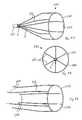
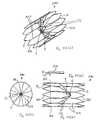
- FIG. 1is an isometric view of a vascular filter according to the invention
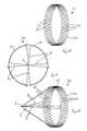
- FIG. 2is an end view of the filter of FIG. 1 ;
- FIG. 3is an isometric view of a support member of the filter of FIG. 1 ;
- FIG. 4is a developed, plan view of two capture members of the filter of FIG. 1 ;
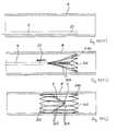
- FIGS. 5 to 9are partially cross-sectional, side views of the filter of FIG. 1 , in use;
- FIGS. 10 to 12are views similar to FIGS. 1 to 3 of another vascular filter according to the invention.
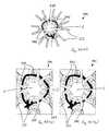
- FIG. 13is an isometric view of another vascular filter according to the invention.
- FIG. 14is an end view of the filter of FIG. 13 in a delivery configuration
- FIG. 15is an end view of the filter of FIG. 13 in a deployed configuration, in use;
- FIGS. 16 and 17are isometric views of support members of other vascular filters according to the invention.
- FIGS. 17( a ) and 17 ( b )are side views of capture members of other vascular filters according to the invention.
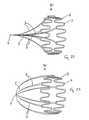
- FIG. 18is an isometric view of capture members of another vascular filter according to the invention.
- FIG. 19is an end view of the capture members of FIG. 18 ;
- FIG. 20is a plan view of one of the capture members of FIG. 18 ;
- FIG. 21is an end view of capture members of another vascular filter according to the invention.
- FIGS. 22 and 23are isometric views of further vascular filters according to the invention.
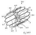
- FIGS. 24 to 26are views similar to FIGS. 1 to 3 of another vascular filter according to the invention.
- FIG. 26( a )is an isometric view of another vascular filter according to the invention.
- FIG. 26( b )is a side view of the filter of FIG. 26( a );
- FIG. 26( c )is an end view of the filter of FIG. 26( a );
- FIG. 26( d )is a side view of the filter of FIG. 26( a ) in a capturing configuration, in use;
- FIG. 26( e )is an end view of the filter of FIG. 26( d ) in the capturing configuration, in use;
- FIGS. 26( f ) and 26 ( g )are views similar to FIGS. 26( d ) and 26 ( e ) of the filter of FIG. 26( a ) in an open configuration, in use;
- FIG. 26( h )is a view similar to FIG. 26( d ) of another vascular filter according to the invention.
- FIGS. 26( i ) and 26 ( j )are views similar to FIGS. 26( b ) and 26 ( c ) of another vascular filter according to the invention.
- FIG. 26( k )is a side view of part of the filter of FIG. 26( i );
- FIG. 26( l )is an end view of the part of FIG. 26( k );
- FIG. 26( m )is an enlarged, end view of the part of FIG. 26( l );
- FIGS. 26( n ) and 26 ( o )are enlarged, end views of parts of the filter of FIG. 26( i );
- FIGS. 27 and 28are views similar to FIGS. 1 and 2 of another vascular filter according to the invention in a capturing configuration
- FIG. 29is an isometric view of capture members and a support member of the filter of FIGS. 27 and 28 in an open configuration
- FIG. 30is an isometric view of a holder member of the filter of FIGS. 27 and 28 ;
- FIG. 31is an isometric view of a holder member of another vascular filter according to the invention.
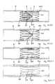
- FIGS. 32 to 36are partially cross-sectional, side views of the filter of FIGS. 27 and 28 , in use;
- FIGS. 37 to 39are views similar to FIGS. 27 to 29 of another vascular filter according to the invention.
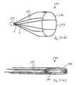
- FIG. 39( a )is an isometric view of another vascular filter according to the invention in a collapsed delivery configuration
- FIG. 39( b )is an isometric view of the filter of FIG. 39( a ) in an expanded deployed configuration
- FIGS. 40 to 44are partially cross-sectional, side views of the filter of FIGS. 39( a ) and 39 ( b ), in use;
- FIGS. 44( a ) and 44 ( b )are views similar to FIGS. 39( a ) and 39 ( b ) of another vascular filter according to the invention.
- FIGS. 45 to 49are partially cross-sectional, side views of the filter of FIGS. 27 and 28 , in use;
- FIGS. 50 and 51are views similar to FIGS. 27 and 29 of a further vascular filter according to the invention.
- FIG. 52is an isometric view of one of the capture members of the filter of FIGS. 50 and 51 ;
- FIG. 52( a )is an isometric view of another vascular filter according to the invention.
- FIG. 52( b )is a side view of the filter of FIG. 52( a );
- FIG. 52( c )is an end view of the filter of FIG. 52( a );
- FIG. 52( d )is an enlarged, side view of part of the filter of FIG. 52( b );
- FIG. 52( e )is an enlarged, end view of part of the filter of FIG. 52( c );
- FIGS. 52( f ) and 52 ( g )are end views of the filter of FIG. 52( e ), in use;
- FIGS. 52( h ) to 52 ( n )are partially cross-sectional, side views of the filter of FIG. 52( a ), in use;
- FIG. 53is an isometric view of another vascular filter according to the invention.
- FIG. 54is a partially cross-sectional, side view of the filter of FIG. 53 , in use;
- FIGS. 55 and 56are isometric views of further vascular filters according to the invention.
- FIGS. 57 and 58are partially cross-sectional, side views of the filter of FIG. 56 , in use;
- FIG. 59is an isometric view of one of the support members of the filter of FIG. 56 ;
- FIGS. 60 to 63are views similar to FIGS. 56 to 59 of another vascular filter according to the invention.
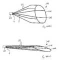
- FIG. 63( a )is an isometric view of another vascular filter according to the invention in a collapsed delivery configuration
- FIG. 63( b )is an isometric view of the filter of FIG. 63( a ) in an expanded deployed configuration
- FIG. 63( c )is a partially cut-away, isometric view of the filter of FIG. 63( a ), in use;
- FIGS. 63( d ) to 63 ( g )are views similar to FIGS. 56 to 59 of another vascular filter according to the invention.
- FIG. 64is a partially cross-sectional, side view of another vascular filter according to the invention, in use.
- FIG. 65is a side view of a part of the filter of FIG. 64 ;
- FIG. 66is a front view of the part of FIG. 65 ;
- FIG. 67is an isometric view of a further vascular filter according to the invention.
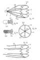
- FIG. 68is an end view of the filter of FIG. 67 in a deployed configuration
- FIG. 69is an end view of the filter of FIG. 67 in a delivery configuration
- FIG. 70is an isometric view of another vascular filter according to the invention.
- FIGS. 71 to 73are views similar to FIGS. 67 to 69 of a further vascular filter according to the invention.
- FIGS. 74 to 76are partially cross-sectional, side views of the filter of FIGS. 71 to 73 , in use;
- FIGS. 77 and 78are views similar to FIGS. 1 and 2 of another vascular filter according to the invention.
- FIG. 79is an isometric view of a further vascular filter according to the invention.
- proximalwill be understood to mean the end closest to a user when carrying out a procedure accessed from a femoral vein, or the caudal end.
- distalwill be understood to mean the end furthest from a user when carrying out a procedure accessed from a femoral vein, or the cranial end.
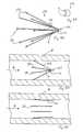
- the vascular filter assemblycomprises a vascular filter 1 according to the invention and a delivery catheter 9 for delivering the filter 1 to a desired location in a blood vessel, such as the inferior vena cava 4 .
- the vascular filter 1is suitable for use as an inferior vena cava filter in the inferior vena cava 4 to capture thrombus 8 passing through the inferior vena cava 4 towards the heart and the lungs.
- the vascular filter 1may thus be used to prevent pulmonaryembolism.
- the filter 1comprises a support hoop 2 and four or more capture arms 3 for capturing thrombus 8 passing through the inferior vena cava 4 .
- the support hoop 2comprises a wire element 5 which extends circumferentially in a sinusoid wave pattern ( FIG. 3 ).
- the support hoop 2is movable between a collapsed delivery configuration ( FIG. 5 ) and an expanded deployed configuration ( FIG. 6 ).
- the support hoop 2extends circumferentially around the internal wall of the inferior vena cava 4 ( FIG. 6 ).
- the support hoop 2is biased radially outwardly towards the deployed configuration.
- the support hoop 2exerts a force radially outwardly on the internal wall of the inferior vena cava 4 .
- the support hoop 2supports the four capture arms 3 in position relative to the wall of the inferior vena cava 4 .
- Each capture arm 3is attached to the support hoop 2 by wrapping or knotting or bonding an end of the capture arm 3 around the wire element 5 ( FIG. 1 .).
- the four capture arms 3extend in a substantially straight line to an apex 6 , where the four capture arms 3 engage each other ( FIG. 1 ). In this manner the four capture arms 3 define a generally conically shaped capture region 7 within which thrombus 8 may be captured ( FIG. 7 ).
- the apex 6is substantially in-line with the longitudinal axis B-B extending through the centre of the inferior vena cava 4 ( FIG. 6 ), and the capture region 7 is located in the region of the centre of the inferior vena cava 4 ( FIG. 6 ).
- the capture arms 3may be taut as shown or hang loosely in the bloodstream.
- the capture arms 3are movable between a collapsed delivery configuration ( FIG. 5 ) and an expanded deployed configuration ( FIG. 6 ).
- FIG. 5When the filter 1 is deployed in the inferior vena cava 4 , the capture arms 3 extend in the direction of blood flow A through the inferior vena cava 4 ( FIG. 6 ).
- the capture arms 3are biased towards the deployed configuration.
- Each of the capture arms 3is of a biodegradable and/or bioabsorbable material.
- the support hoop 2may also be formed from a biodegradable and/or bioabsorbable material.
- the filter element 1has a taper configuration.
- the woven biodegradable arms 3have a double taper ( FIG. 4 ).
- the element 3may equally be formed from a monofilament or multi-filament structure.
- the filter 1has an even number of elements 3 ( FIG. 2 ). In an alternative configuration the filter may have an odd number of elements 3 .
- the multiple elements 3degrade based on circumference from centre to outside of the vessel 4 .
- the delivery catheter 9comprises a restraining sheath 10 which covers at least part of the collapsed filter 1 in a delivery configuration ( FIG. 5 ).
- the sheath 10is movable proximally relative to the filter 1 to a deployed configuration to uncover the filter 1 and thus facilitate deployment of the filter 1 ( FIG. 6 ).
- the filter element 3 with the tapered configurationmay be formed in a variety of possible manners. For example by casting, dipping into a polymer solution with an extraction rate controlled to allow evaporation of solvent and deposition of polymer.
- the filter element 3may be alternatively formed by extruded bump tubing, in which case the thermoplastic polymer is extruded into the tapered configuration.
- the support hoop 2 and the four capture arms 3are collapsed to the delivery configuration, and at least partially loaded into the delivery catheter 9 .
- the delivery catheter 9is advanced through the inferior vena cava 4 until the collapsed filter 1 reaches the desired location in the inferior vena cava 4 ( FIG. 5 )
- the restraining sheath 10 of the delivery catheter 9is then moved proximally relative to the filter 1 to fully uncover the filter 1 .
- the support hoop 2 and the capture arms 3move from the collapsed delivery configuration to the expanded deployed configuration ( FIG. 6 ).
- the support hoop 2exerts a radially outwardly force on the internal wall of the inferior vena cava 4 to support the capture arms 3 in the desired position in the inferior vena cava 4 .
- the thrombus 8In the event of thrombus 8 passing through the inferior vena cava 4 towards the heart and the lungs, the thrombus 8 will be captured in the capture region 7 of the filter 1 ( FIG. 7 ). The thrombus 8 will thus be prevented from passing into the heart and the lungs which could otherwise lead to pulmonaryembolism. The captured thrombus 8 will gradually be broken down by the body into smaller size particles 100 , which will significantly reduce the risk of embolism ( FIG. 8 ).
- the capture arms 3Due to the biodegradable/bioabsorbable material of the capture arms 3 , the capture arms 3 will eventually biodegrade/bioabsorb ( FIG. 9 ). Thus only the support hoop 2 will remain in the inferior vena cava 4 .
- the delivery systems for delivery of the vena cava filter 1may employ push and/or pull from either the jugular or femoral side.
- the delivery systemmay use rotational deployment.
- the delivery systemmay be a rapid exchange system for single operator deployment.
- the delivery systemmay use linear ratchet deployment and/or rotational ratchet deployment.
- the operatorpreferably keeps purchase on the filter 1 until the location is finalised.
- the delivery systemmay be a push forward system. In this case the operator aligns the distal catheter marker to the location of mural attachment, and then pushes out the filter 1 .
- part or all of the support hoop 2may be biodegradable/bioabsorbable, so that no part of the filter 1 will remain permanently in the inferior vena cava 4 .
- FIGS. 10 to 12there is illustrated another vascular filter 20 according to the invention, which is similar to the vascular filter 1 of FIGS. 1 to 9 , and similar elements in FIGS. 10 to 12 are assigned the same reference numerals.
- the support hoop 21is provided in the form of a mesh or trellis 23 .
- the mesh/trellis 23comprises a number of openings 22 therethrough.
- the trellis filter 20 of FIGS. 10 to 12is similar to a mural trellis with a number of woven elements 3 extending to a proximal point 6 .
- the elements 3may be joined, or may be not joined at the apex 6 .
- the filter 20may be of metallic material and/or of biodegradable material.
- the filter 20may be a combination of a metallic mural 21 and biodegradable elements 3 .
- the trellis designmay be either self expanding or balloon expandable.
- the trellis 23comprises thin wires with weave fixed at ends to prevent unravelling. In another embodiment the trellis 23 comprises thin wires interwoven with free ends. Either embodiment may be used for the mural element 21 .
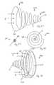
- FIGS. 13 to 15illustrate a further vascular filter 30 according to the invention, which is similar to the vascular filter 20 of FIGS. 10 to 12 , and similar elements in FIGS. 13 to 15 are assigned the same reference numerals.
- the support hoop 31comprises a body portion 32 and a plurality of openings 33 extending through the body portion 32 .
- the support hoop 31In the collapsed delivery configuration the support hoop 31 has a spiral configuration ( FIG. 14 ). In the expanded deployed configuration, one end 34 of the support hoop 31 overlaps the other end 35 of the support hoop 31 .
- the openings 33 in the support hoop 31facilitate tissue ingrowth 36 ( FIG. 15 ).
- the support hoop 31may be a coil based system.
- FIG. 14illustrates the closed configuration
- FIG. 15illustrates the open configuration.
- the wall of the support hoop 31may be planar or be of an open structure ( FIG. 13 ).
- the element structure 3may be knotted using sutures to the support hoop 31 .
- FIG. 16illustrates a support hoop 40 which comprises a wire element 41 which extends circumferentially in a jagged wave pattern
- FIG. 17illustrates a support hoop 50 which comprises a body portion 51 which extends circumferentially in a square wave pattern.
- the support hoopmay have a peak to peak design in the circular deployed configuration ( FIG. 16 ).
- the support hoopmay be formed of fixed length wires joined at each end to the wire on either side ( FIG. 16 ), or alternatively may be cut from a single sheet ( FIG. 17 ).
- FIGS. 16 and 17may also be suitable for use as a stent.
- the capture armsmay engage each other at the apex 6 in a variety of possible shapes and configurations.
- the capture arms 3may be fixedly attached to one another by a weld joint, solder or adhesive 55 at the apex 6 ( FIG. 17( a )).
- the capture arms 3may be integrally formed from a single element 56 bent back on itself to form the capture arms 3 ( FIG. 17( b )).
- each capture arm 60terminates in a curved, pointed tip 61 ( FIG. 20) .
- the tips 61nest with one another at the apex 6 ( FIG. 19 ).
- each capture arm 70terminates in a straight, pointed tip 71 .
- the tips 71nest with one another at the apex 6 ( FIG. 21 ).
- FIG. 19illustrates the nesting elements 60 .
- the geometrics of the elements 60are configured to nest at the apex 6 of the filter such that a frame is erected during deployment that will not allow significant thrombus to pass.
- FIG. 22there is illustrated another vascular filter 80 according to the invention, which is similar to the vascular filter 1 of FIGS. 1 to 9 , and similar elements in FIG. 22 are assigned the same reference numerals.
- the capture arms 3extend in a curve to the apex 6 .
- the concave portion of the curvefaces radially outwardly.
- FIG. 23there is illustrated a further vascular filter 90 according to the invention, which is similar to the vascular filter 80 of FIG. 22 , and similar elements in FIG. 23 are assigned the same reference numerals.
- the capture arms 3extend in a curve to the apex 6 .
- the convex portion of the curvefaces radially outwardly.
- These capture arms 3may be moulded or machined into the configurations shown.
- Possible geometries for the vena cava filterinclude conical shape, concave shape, and convex shape geometries.
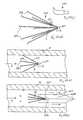
- FIGS. 24 to 26illustrate another vascular filter 110 according to the invention, which is similar to the vascular filter 1 of FIGS. 1 to 9 , and similar elements in FIGS. 24 to 26 are assigned the same reference numerals.
- the capture arm 112is provided integral with the support hoop 2 .
- the capture arm 112is provided as an extension of one of the sinusoid curves of the wire element 5 ( FIG. 26 ).
- the other three capture arms 113are similar to the capture arms 3 described previously with reference to FIGS. 1 to 9 .
- the capture arms 112 , 113define an offset conically shaped capture region 111 .
- the apex 6is offset from the longitudinal axis B-B extending through the centre of the inferior vena cava 4 , and the capture region 111 is located in the region of the internal wall of the inferior vena cava 4 .
- the support hoop 2may be a Nitinol (Ni Ti) sinusoid or may be a stainless steel sinusoid. Alternatively the support hoop 2 may be of a zigzag or crown design.
- the elements 113may be of Nitinol stainless steel, titanium or a biodegradable material.
- the filter 110has a single extended element 112 .
- the offset filter 110directs embolus to the side wall. This arrangement may be advantageous. It may allow more blood flow at the centre of the vena cava 4 by directing thrombus 8 away from the centre of blood flow.
- taper elementscould be used.
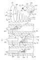
- FIGS. 26( a ) to 26 ( g )there is illustrated another vascular filter 300 according to the invention, which is similar to the vascular filter 1 of FIGS. 1 to 9 , and similar elements in FIGS. 26( a ) to 26 ( g ) are assigned the same reference numerals.
- the filter 300comprises a proximal support hoop 302 at the proximal end of the filter 300 , a distal support hoop 312 at the distal end of the filter 300 , and a plurality of support struts 303 extending between the proximal support hoop 302 and the distal support hoop 312 .
- the proximal support hoop 302comprises a wire element 5 which extends circumferentially around the wall of the inferior vena cava 4 in a sinusoid wave pattern.
- the distal support hoop 312comprises a wire element 5 which extends circumferentially around the wall of the inferior vena cava 4 in a sinusoid wave pattern.
- the support struts 303extend longitudinally along the wall of the inferior vena cava 4 .
- the support struts 303connect the proximal support hoop 302 to the distal support hoop 312 .
- the proximal support hoop 302 , the distal support hoops 312 and the support struts 303are formed integrally.
- the proximal support hoop 302 , the distal support hoop 312 and the support struts 303may be of a shape-memory material, such as Nitinol.
- the distal end of the distal support hoop 312is located distally of the capture arms 3 and the apex 6
- the proximal end of the proximal support hoop 302is located proximally of the capture arms 3 .
- the filter 300also comprises a plurality of integral, or joined metal, or biodegradable/bioabsorbable barbs 301 to assist in anchoring the filter 300 relative to the inferior vena cava 4 .
- the filter 300comprises two or more tensioning arms 304 and two or more connecting arms 305 .
- Each tensioning arm 304is provided in the form of a cantilever arm.
- the distal end of the tensioning arm 304is located distally of the apex 6
- the proximal end of the tensioning arm 304is located proximally of the apex 6 .
- the tensioning arms 304are movable between a capturing configuration ( FIG. 26( d )) and an open configuration ( FIG. 26( f )).
- the tensioning arms 304are inclined distally inwardly relative to the longitudinal axis of the inferior vena cava 4 .
- the tensioning arms 304are aligned parallel to the wall of the inferior vena cava 4 .
- the tensioning arms 304are biased towards the open configuration.
- the tensioning arms 304may be of a shape-memory material, such as Nitinol.
- the connecting arms 305connect the tensioning arms 304 to the capture arms 3 at the apex 6 .
- the tensioning arms 304act to tension the capture arms 3 to prevent the capture arms 3 from becoming slack and/or to prevent the apex 6 from moving off-centre.
- the tensioning arms 304may originate at the caudal end of the filter 300 .
- the connecting arms 305are of a biodegradable/bioabsorbable material, in this case.
- the connecting arms 305will eventually biodegrade/bioabsorb. This enables the tensioning arms 304 to move from the capturing configuration to the open configuration. Only the proximal support hoop 302 , the distal support hoop 312 , the support struts 303 and the tensioning arms 304 remain in the inferior vena cava 4 ( FIG. 26( f )).
- FIGS. 26( a ) to 26 ( g )illustrate the net filter design.
- FIG. 26( b )illustrates the filtering elements 3 , the tensioning element 304 , the tensioning filament 305 , and the crown elements 302 , 312 .
- the net filter designcomprises the Nitinol frame 302 , 303 , 312 with a tubular profile which has the number of bioabsorbable filaments 3 attached and spanning across its diameter in order to create a filter capable of trapping blood clots.
- the Nitinol frameis a single component which comprises zigzag type design features called crowns 302 , 312 at both its ends. This design allows the device 300 to be crimped or reduced in diameter so that it can be delivered through the vascular system in a catheter of much smaller diameter than the vena cava 4 .
- the elastic energy in the deformed crowns 302 , 312enables the device 300 to expand to the vessel diameter.
- the componentis designed so these crowns 302 , 312 exert outward radial pressure against the internal wall of the vena cava 4 within the range of vessels typically encountered.
- the two sets of crowns 302 , 312are linked by the connecting elements 303 .
- the filter 300is created by the number of bioabsorbable filaments 3 which span the vessel lumen.
- the absorbable elements 3take up a tensioned conical configuration.
- the materials usedhave a known degradation profile such that they will provide protection to the patient while they are at risk and once this risk is minimised the materials will breakdown and become metabolised.
- the tensioning feature 304 on the Nitinol framewill spring back to the vessel wall with sufficient outward pressure to promote endothelial covering and encapsulation in tissue preventing or reducing the long term complications of obstructing blood flow associated with permanent vena cava filters.
- the small barbs 301are located at the cranial end of the connecting elements 303 . They have sharp edges that are angled to anchor into the vessel tissue.
- the designfeatures barbs 301 which may face in either direction, or may have separate barbs 301 facing in opposite directions.
- the filter 300comprising bioabsorbable elements 3 creates a rigid conical shape across a wide range of vessel diameters. This may be achieved using the tensioning system shown in FIG. 26( b ).
- the short metallic cantilever type elements 304are connected to the tensioning filament 305 that pulls the filtering element 3 in the cranial direction when positioned in the vessel 4 with a relatively smaller diameter.
- These metallic elements 304may be visualised during implantation using fluoroscopy of other imaging technology and thus act as a radiopaque indicator as to whether the filter elements 3 have degraded or not.
- the metallic frame 304bends inward to create the cone independent of vessel size. This also creates a radiopaque indicator as to whether the filter 300 is still functioning.
- FIG. 26( h )there is illustrated another vascular filter 320 according to the invention, which is similar to the vascular filter 300 of FIGS. 26( a ) to 26 ( g ), and similar elements in FIG. 26( h ) are assigned the same reference numerals.
- tensioning arms 304are inclined proximally inwardly relative to the longitudinal axis of the inferior vena cava 4 in the capturing configuration.
- FIG. 26( h )illustrates the metallic tensioning element 304 , the support frame 312 , the bioabsorbable filter elements 3 , and the bioabsorbable tensioning element 305 .
- the filter 320has the bioabsorbable elements 3 spanning across the vessel lumen protecting the patient while they are at risk of a pulmonary embolism. These elements 3 break down when the risk has passed.
- the elements 3are connected to the metal frame which promotes tissue ingrowth and becomes encapsulated in the vessel wall similar to a stent.
- the filter 320has the ability to align the elements 3 in the centre of the vessel 4 so that they provide the maximum clot trapping ability.
- a wide range of blood vessel diametersmay be encountered.
- the inferior vena cava 4may be in the range of 16 mm to 27 mm.
- the filter 320has the ability to relay visually whether the elements 3 have absorbed or not, i.e. whether the filter 320 is still functioning and the patient protected from pulmonaryembolism.
- the filter 320has one or more tensioning elements 304 that remove any slack in the filter elements 3 by increasing the filter cone angle as the diameter increases.
- the small cantilever type metallic elements 304are deformed inward by the bioabsorbable element 305 to achieve the stretching out of the bioabsorbable filter elements 3 until they are tense and central in the vessel.
- the device 320may be x-rayed to establish if it is in the filter configuration or if it has converted by assessing the angle of the metallic tensioning elements 304 .
- FIGS. 26( i ) to 26 ( m )illustrate another vascular filter 330 according to the invention, which is similar to the vascular filter 300 of FIGS. 26( a ) to 26 ( g ), and similar elements in FIGS. 26( i ) to 26 ( m ) are assigned the same reference numerals.
- the filter 330comprises a plurality of linking arms 331 to link each capture arm 3 to the adjacent capture arm 3 .
- the linking arms 331are of a biodegradable/bioabsorbable material.
- the capture arms 3comprise a plurality of openings 332 through the wall of the capture arms 3 at the apex 6 .
- the openings 332reduce the tensile strength of the capture arms 3 . In this manner the capture arms 3 are provided with predetermined failure points to control biodegrading/bioabsorbing of the capture arms 3 .
- each linking arm 331comprises an opening 333 through the wall of the linking arm 331 .
- the opening 333reduces the tensile strength of the linking arm 331 .
- the linking arm 331is provided with a predetermined failure point to control biodegrading/bioabsorbing of the linking arm 331 .
- FIG. 26( i )illustrates the tensioning arm 304 , and the tensioning filament 305 .
- the filter 330has bioabsorbable elements 3 spanning across the vessel lumen protecting the patient while they are at risk of a pulmonary embolism. These elements 3 break down when the risk has passed.
- the elements 3are connected to the metal frame which will promote tissue ingrowth and become encapsulated in the vessel wall similar to a stent.
- Maintaining the conical shape in which any thromboemboli caught by the filter 330 are stored in a central locationmay be an important feature, as this exposes the clot 8 to the highest flow rates. Consequently the clot 8 may be lysed in a shorter time period and the risk of IVC occlusion due to thrombosis may be reduced or minimised.
- the absorbable net design 330is manufactured in one component and may offer a more consistent concial filter shape and clot trapping efficiency than a series of single filaments 3 .
- the netcan adjust to varying diameters by means of the tensioning system provided by the tensioning filament 305 and the tensioning arm 304 .
- the filter 330may be made by producing a cone shaped film and cutting a shape in the film to produce a filter capable of protecting the patient from pulmonary embolism. This may be achieved by solution casting a polymer film and cutting away material to achieve various filter shapes that preserve blood flow yet filter pieces of thrombi efficiently. The cutting process would be achieved using laser technology to ensure accurate dimensioning and freedom of filter design.
- the componentmay be designed so that it will degrade initially in a controlled location by designing areas of reduced cross sectional area into the device. This will have the advantage of allowing the net to reduce to single strands and minimise the risk of a clinically significant pulmonary emboli.
- the componentmay be made from a compliant material such as Polycaprolactone and copolymers of caprolactone and Lactide and/or Gylcolide.
- a compliant materialsuch as Polycaprolactone and copolymers of caprolactone and Lactide and/or Gylcolide.
- Other suitable polymerswould be polymers derived from Polyhydroxybutyrate.
- FIGS. 27 to 30 and 32 to 36there is illustrated a further vascular filter 120 according to the invention, which is similar to the filter 1 of FIGS. 1 to 9 , and similar elements in FIGS. 27 to 30 and 32 to 36 are assigned the same reference numerals.
- the filter 120comprises six capture arms 121 integrally formed with the support hoop 2 .
- the capture arms 121are movable between a capturing configuration ( FIG. 27 ) and an open configuration ( FIG. 29 ).
- the capture arms 121extend to the apex 6 and define the conically shaped capture region 7 .
- the capture arms 121are biased towards the open configuration, and a holder tube 122 is provided around the ends of the capture arms 121 to hold the capture arms 121 in the capturing configuration.
- the holder tube 122is biodegradable and/or bioabsorbable. Upon biodegrading/bioabsorbing of the holder tube 122 , the capture arms 121 are free to move from the capturing configuration to the open configuration ( FIG. 29 ).
- the capture arms 121are not biodegradable or bioabsorbable.
- the support hoop 2In use, in the deployed configuration, the support hoop 2 is partially embedded in the internal wall of the inferior vena cava 4 to support the capture arms 121 in the desired position in the inferior vena cava 4 ( FIG. 33 ). Due to the biodegradable/bioabsorbable material of the holder tube 122 , the holder tube 122 will eventually biodegrade/bioabsorb ( FIG. 36 ), which enables the capture arms 121 to move from the capturing configuration to the open configuration. The support hoop 2 and the capture arms 121 remain in the inferior vena cava 4 .
- the holder memberwhich holds the capture arms 121 in the capturing configuration.
- the holder memberis provided in the form of a bioabsorbable and/or biodegradable coil 130 around the ends of the capture arms 121 to hold the capture arms 121 in the capturing configuration.
- the shape memory of the capture arms 121are configured to remember a tubular shape.
- the only biodegradable element of the filter 120is the holder 122 at the apex 6 of the filter 120 .
- the apex suture 130bioresolves and the arms 121 revert to the tubular configuration ( FIG. 31 ).
- the cap 122 at the apex 6can be bio-resorbed ( FIG. 30 ).
- the filter arms 121are not retrieved in this embodiment.
- the bio-resorbable point 122allows the filler (Ni Ti) 121 or other material to relax to the wall and remain in the body.
- the filter cap 122may not be resorbable but may be retrieved by a snare or other removal device.
- Another alternativeis to replace the bio-resorbable cap by way of an interventional procedure to extend the period for which protection is provided to the patient.
- a metallic or bio-stable polymer elementmay be used to replace the filter cap to convert the implant device into a permanent implant.
- the permanent configurationmay be welded or otherwise permanently joined at the apex.
- FIGS. 37 to 39there is illustrated another vascular filter 140 according to the invention, which is similar to the vascular filter 120 of FIGS. 27 to 30 and 32 to 36 , and similar elements in FIGS. 37 to 39 are assigned the same reference numerals.
- the support hoop 141comprises a wire element 142 which extends circumferentially in a plane.
- each capture arm 121curves radially outwardly.
- FIGS. 39( a ) to 44illustrate another vascular filter 145 according to the invention, which is similar to the vascular filter 140 of FIGS. 37 to 39 , and similar elements in FIGS. 39( a ) to 44 are assigned the same reference numerals.
- the support hoop 146comprises a wire element 147 which extends circumferentially in a sinusoid pattern in the collapsed delivery configuration ( FIG. 39( a )), and which extends circumferentially in a plane in the expanded deployed configuration ( FIG. 39( b )).
- the filter 145may be delivered to the desired location in the inferior vena cava 4 and deployed at the desired location using the delivery catheter 9 in a manner similar to that described previously with reference to FIGS. 1 to 9 .
- FIGS. 44( a ) and 44 ( b )there is illustrated another vascular filter 148 according to the invention, which is similar to the vascular filter 140 of FIGS. 37 to 39 , and similar elements in FIGS. 44( a ) and 44 ( b ) are assigned the same reference numerals.
- the support hoop 141comprises the wire element 142 which extends circumferentially in a plane.
- the plane of the support hoop 141is inclined relative to a plane perpendicular to the longitudinal axis of the inferior vena cava 4 ( FIG. 44( a )).
- the plane of the support hoop 141may or may not be inclined relative to the plane perpendicular to the longitudinal axis of the inferior vena cava 4 ( FIG. 44( b )).
- the filter 120may be delivered to the desired location in the inferior vena cava 4 and deployed at the desired location using another delivery catheter 150 ( FIGS. 45 to 49 ).
- the delivery catheter 150comprises a balloon member 151 which is inflatable from a collapsed delivery configuration ( FIG. 45 ) to an expanded deployed configuration ( FIG. 46 ), and deflatable from the expanded deployed configuration to the collapsed delivery configuration ( FIG. 47 ).
- the support hoop 2 and the six capture arms 121are collapsed to the delivery configuration, and mounted around the balloon member 151 .
- the delivery catheter 150is advanced through the inferior vena cava 4 until the collapsed filter 120 reaches the desired location in the inferior vena cava 4 ( FIG. 45 ).
- the balloon member 151is then inflated to move the support hoop 2 and the capture arms 121 from the collapsed delivery configuration to the expanded deployed configuration ( FIG. 46 ).
- the support hoop 2exerts a radially outward force on the internal wall of the interior vena cava 4 to support the capture arms 121 in the desired position in the inferior vena cava 4 .
- the balloon member 151is deflated from the expanded deployed configuration to the collapsed delivery configuration, and the delivery catheter 150 is withdrawn ( FIG. 47 ).
- the thrombus 8In the event of thrombus 8 passing through the inferior vena cava 4 towards the heart and the lungs, the thrombus 8 will be captured in the capture region 7 of the filter 120 ( FIG. 48 ). The captured thrombus 8 will gradually be broken down by the body into smaller size particles, which significantly reduce the risk of embolism.
- the holder tube 122Due to the biodegradable/bioabsorbable material of the holder tube 122 , the holder tube 122 will eventually biodegrade/bioabsorb ( FIG. 49 ), which enables the capture arms 121 to move from the capturing configuration to the open configuration.
- the support hoop 2 and the capture arms 121remain in the inferior vena cava 4 .
- FIGS. 45 to 49illustrate the balloon expandable vena cava filter 120 which has non shape memory metals or polymers.
- the filter 120is mounted onto the balloon catheter 150 .
- the distal tip of the balloonmay be inverted to minimise space used by the balloon.
- a tip markermay be incorporated to allow guidewire pull back for deployment.
- FIGS. 50 to 52illustrate another vascular filter 160 according to the invention, which is similar to the vascular filter 120 of FIGS. 27 to 30 and 32 to 36 and similar elements in FIGS. 50 to 52 are assigned the same reference numerals.
- each capture arm 161is formed separately from the support hoop 2 and is attached to the support hoop 2 in a snap-fit arrangement.
- FIG. 52illustrates the moulded element 161 which is snap fitted to the sinusoidal wire 5 .
- the capture arms 161may be of polymer and may be welded to the degradable holder tube 122 at the apex 6 .
- the capture arm parts 161are biased towards the open position.
- FIGS. 52( a ) to 52 ( n )there is illustrated a further vascular filter 340 according to the invention, which is similar to the vascular filter 120 of FIGS. 27 to 30 and 32 to 36 , and similar elements in FIGS. 52( a ) to 52 ( n ) are assigned the same reference numerals.
- the filter 340comprises a proximal support hoop 302 , a distal support hoop 312 , a plurality of support struts 303 , and a plurality of biodegradable/bioabsorbable barbs 301 , similar to those described previously with reference to FIGS. 26( a ) to 26 ( g ).
- An opening 341is provided at the distal end of each of the capture arms 121 , and a suture 342 extends through the opening 341 to hold the capture arms 121 in the capturing configuration.
- the suture 342is of a biodegradable/bioabsorbable material.
- the suture 342comprises an opening 343 through the wall of the suture 342 .
- the opening 343reduces the tensile strength of the suture 342 . In this manner the suture 342 is provided with a predetermined failure point to control biodegrading/bioabsorbing of the suture 342 .
- FIGS. 52( a ) to 52 ( n )illustrate the apex filter design.
- FIG. 52( b )illustrates the filter element 121 , the crown elements 302 , 312 , and the connecting elements 303 . While shown in a straight configuration, the elements 303 connecting the cranial and caudal ends may include curved or angled elements. Such configurations may provide reduced lateral stiffness. Generally, the elements 303 will nest together for delivery in the delivery system prior to deployment in the vena cava 4 .
- the apex designcomprises the Nitinol frame 302 , 312 , 203 , 121 and the small bioabsorbable element 342 .
- the Nitinol frameis designed with thin elements that allow the device 340 to assume three separate configurations during its use:—
- the componenthas a zigzag type support feature at both its ends 302 , 312 referred to in this specification as a crown, which allows the device 340 to be crimped or reduced in diameter so that it can be delivered through the vascular system in a catheter of much smaller diameter than the inferior vena cava 4 .
- the elastic energy in the deformed crowns 302 , 312enable the device 340 to expand to the vessel diameter.
- the componentis designed so these crowns 302 , 312 exert outward radial pressure against the internal wall of the vena cava 4 within the range of vessels typically encountered.
- the two sets of crowns 302 , 312are linked by connecting elements 303 , and originating from the caudal ends of these connecting elements 303 are thin filter elements 121 which have a V-shape. These filter elements 121 can be mechanically deformed and retained in a central conical shape in order to create a filter configuration.
- the componentis designed so that the crown elements 302 , 312 and connecting elements 303 are relatively stiff versus the filter elements 121 , making the outer profile of the component substantially cylindrical when the filter elements 121 are deformed inward. This ensures that the crown elements 302 , 312 and connecting elements 303 remain in contact with the wall while the device 340 is in the filter configuration promoting tissue ingrowth and minimising the risk of complications with vena cava filters such as migration and perforation.
- the filter elements 121are held together by means of the filament 342 made from a small volume of bioabsorbable material.
- the materialhas a known degradation profile such that it has sufficient strength to retain the metal filter elements 121 in the filtering configuration while the patient is at risk of a large embolus passing through the vena cava 4 .
- the filament 342will have degraded sufficiently for the elastic force of the metal filter elements 121 to break the filament 342 and expand outward.
- the filament 342is tied through small eyelet features 341 at the end of the filter elements 121 and a knot is formed around one filter 121 such that once the filament 342 breaks it stays attached to that filter element 121 .
- the device 340assumes its open configuration.
- the filter elements 121spring back to the vessel wall and exert sufficient pressure to promote endothelial covering and encapsulation in tissue, negating any long term complications associated with obstructing the blood flow in the vena cava 4 .
- barbs 301are located at the cranial end of the connecting elements 303 . They have sharp edges that are angled to anchor into the vessel tissue.
- the designfeatures barbs 301 which may face in either direction, or may have separate barbs 301 facing in opposite directions.
- FIGS. 52( a ) to 52 ( n )illustrate the concept for the convertible blood vessel filter 340 where the device 340 has three configurations, the delivery configuration, filter configuration and the open configuration.
- the filter configurationis used to trap thrombus while a patient may be at risk of a thromboembolic event; once the risk has passed the device 340 can then be converted to the open configuration which no longer disrupts blood flow.
- the filter configurationis achieved by mechanically deforming the elements 121 of the device 340 and securing these filter elements 121 together at a point within the blood vessel.
- the filter elements 121are held by the bioabsorbable securement feature 342 , which may be released to allow the elements 121 to revert back to the open configuration.
- the device 340that has a substantially cylindrical outer profile with sufficient mechanical stiffness to maintain the cylindrical outer profile when the filter elements 121 of low mechanical stiffness are deformed centrally.
- the substantially cylindrical outer profileallows the device 340 to have significant vessel contact over a large area in both the open and filter configurations substantially reducing the risk of clinical issues such as perforation, migration and tilting.
- the device 340is constructed of a superelastic metal or polymer. In one embodiment the device is constructed of Nitinol.
- the device 340is one piece cut from a laser machined tube, expanded and heat set. In another embodiment the device 340 is an assembly of more than one part from either the same material or from differing superelastic materials.
- Having a substantially cylindrical outer profileprovides a significant advantage in terms of deployment. As the device 340 exits the delivery system, the initial portion of the device 340 will contact the vessel wall prior to full device exiting of the delivery system. This allows for accurate placement of the device 340 , as illustrated in FIG. 52( i ).
- a short length of filamentin the order of 1-10 cms of diameter >0.4 mm, more ideally less than 0.3 mm, even more ideally less than 0.2 mm may be used.
- FIG. 52( e )illustrates the bioabsorbable element 342 which is configured to break at some point away from the knot.
- the element 342is knotted around the frame 121 .
- the element 342remains connected to one element 121 of the frame after the filament 342 breaks.
- the suture 342may have a particularly small volume of bioabsorbable material.
- the suture 342may have a diameter of less than 0.4 mm, ideally less than 0.3 mm, more ideally less than 0.2 mm.
- the filament material 342is tied to the ends of the capture elements 121 in such a way that when it breaks the filament 342 remains tied to one of the capture elements 121 and becomes apposed to the vessel wall. This results in the bioabsorbable material 342 becoming encapsulated in tissue and absorbing therein. This may be achieved by knotting the suture 342 around one of the arms 121 as shown in FIG. 52( e ). The suture 342 will break at a point away from the knot and release the capture element arms 121 bringing the suture 342 with one of the arms 121 .
- Introducing a point 343 along the suture 342 that is more susceptible to biodegradationis beneficial with this type of design. This may be achieved by having the region 343 that has a lower cross sectional area than the remainder of the filament 342 .
- this area of reduced cross sectionis achieved by lasering a small hole 343 through the filament material 342 .
- the diameter of the hole 343would be less than ⁇ 0.1 mm. More ideally the diameter of the hole 343 would be ⁇ 0.05 mm.
- FIG. 52( f )illustrates the small hole 343 machined in the filament 342 to create the controlled break area.
- the filter elements 342may have multiple microscopic holes or notches drilled or formed therein to provide a locus for failure away from the joins or knots. This may be beneficial in that the location of eventual failure of the elements 342 is known. Varying the size of the holes will allow the time to failure for each element 342 to be controlled individually. Larger holes will result in a shorter time to failure. This may be beneficial in allowing the timing of degradation products being released into the bloodstream to be controlled. Alternatively, varying the diameter of the elements 342 to sequentially larger diameters will allow similar control over the time to failure of the filter elements 342 .
- the reduced cross sectionmay alternatively be achieved by softening the material with heat and creating a ‘necked down’ region which has a reduced cross sectional area.
- the convertible filter 340anchors securely at its deployment site and minimises risk of migration.
- the filter 340incorporates the small sharp barbs 301 facing either direction which add fixation points for the device 340 and combined with the radial force of the design, minimise any risk of migration.
- the barbs 301may be made of a bioabsorbable material which degrades and metabolises after the device 340 has been encapsulated in tissue. This will prevent any long term effects due to erosion and/or perforation of the vena cava 4 caused by the barb 301 .
- Suitable bioabsorbable materials for a bioabsorbable barb 301 and/or for the filter filament 342include:
- FIGS. 52( a ) to 52 ( n )provides a stent-like shape to the vena cava filter 340 giving it a cylindrical outer profile. This design prevents issues such as tilting and perforation and allows for accurate deployment within the vessel 4 .
- the frame designallows the filter elements 121 to be deformed centrally without affecting the cylindrical outer profile and once the risk period for thromboemboli has passed allows the filter 121 to spring back to a position apposed to the vessel wall.
- the bioabsorbable element 342stays attached to the frame 121 after opening. Controlling the break up of the bioabsorbable element 342 and minimising the amount of material that embolises may be achieved by tying the filament 342 around one filter element end. Therefore, once the element 342 breaks, it will remain attached to the frame 121 and become encapsulated in the vein wall along with the frame 121 . A controlled break point 343 may be added to the absorbable element 342 away from the knot by any of the means described herein.
- barbs 301that are bioabsorbable offers a significant advantage in that they are only required in the short-term and once the frame becomes encapsulated in the vein wall they will no longer be required thus preventing any potential long-term erosion effects of having the barbs 301 on the frame.
- FIG. 52( h )illustrates the vena cava 4 being accessed transluminally using the delivery catheter 9 .
- FIG. 52( i )illustrates the vena cava filter 340 being deployed by pulling back the delivery catheter sheath 10 .
- FIG. 520)illustrates the device 340 deployed filtering thromboemboli within the vena cava 4 .
- FIG. 52( k )illustrates the device 340 capturing a large clot 8 that may have caused a pulmonary embolism.
- FIG. 52( l )illustrates the filter 340 in situ after the blood's own natural lysing processes have broken down the clot 8 over time.
- FIG. 52( m )illustrates that once the threat of pulmonary embolism has passed, the bioabsorbable retainer 342 breaks down and allows the filter arms 121 to become apposed to the wall.
- FIG. 52( n )illustrates that over time the frame 340 becomes encapsulated in tissue.
- FIGS. 53 and 54there is illustrated another vascular filter 170 according to the invention, which is similar to the vascular filter 120 of FIGS. 27 to 30 and 32 to 36 , and similar elements in FIGS. 53 and 54 are assigned the same reference numerals.
- the capture arms 121extend in the direction opposite to the direction of blood flow A through the inferior vena cava 4 ( FIG. 54 ).
- the capture arms 121define an annular shaped capture region 171 located in the region of the internal wall of the inferior vena cava 4 .
- FIG. 53illustrates the Nitinol sinusoid 2 and the inverted elements 121 . This configuration acts to divert embolism 8 from the centre of the flow to be retained close to the side of the vessel 4 . It creates a type of receiver region 171 to receive the thrombus 8 .
- FIG. 55there is illustrated another vascular filter 180 according to the invention, which is similar to the vascular filter 90 of FIG. 23 , and similar elements in FIG. 55 are assigned the same reference numerals.
- the filter 180comprises six balance arms 181 extending from the support hoop 2 in the opposite direction to the capture arms 3 .
- Each balance arm 181is attached to the support hoop 2 by wrapping an end of the balance arm 181 around the wire element 5 .
- Each balance arm 181is of a biodegradable and/or bioabsorbable material.
- Each balance arm 181extends in a curve.
- the convex portion of the curvefaces radially outwardly.
- the balance arms 181In use, due to the biodegradable/bioabsorbable material of the balance arms 181 , the balance arms 181 will eventually biodegrade/bioabsorb. Thus only the support hoop 2 will remain in the interior vena cava 4 .
- the filter 180may be of varying porosity. More space may be provided in the distal sections.
- the filter 180has a ball shape. There are no sharp edges on a ball. This may allow enhanced radial force on the vena cava wall for enhanced anchoring.
- FIGS. 56 to 59illustrate another vascular filter 190 according to the invention, which is similar to the vascular filter 120 of FIGS. 27 to 30 and 32 to 36 and similar elements in FIGS. 56 to 59 are assigned the same reference numerals.
- the filter 190comprises a plurality of support anchors 191 instead of the support hoop.
- a support anchor 191is fixedly attached to a proximal end of each capture arm 121 .
- the support anchors 191are embedded into the internal wall of the inferior vena cava 4 ( FIG. 57 ). In this manner the support anchors 191 support the capture arms 121 in position relative to the wall of the inferior vena cava 4 .
- the biodegradable barbs 191secure the filter device 190 at the time of implantation and are resorbed either fully or partially at the time of retrieval.
- bio-resorbable barbs on any implantcould reduce long term implantation problems.
- a barbcould be over-moulded or formed onto any metallic or polymeric structure and formed into the desired shape to anchor it to the vascular or anatomical structure.
- the barbscould be moulded, machined, or formed from pre-forms such as extruded tiles or rods.
- the benefitsinclude the fact that after a period of time the barb would be absorbed and the irritation removed from the implant site.
- Barbscould be attached to the end of or any intermediate point that could come in contact with a blood vessel during implantation by means of endovascular or surgical treatment.
- FIGS. 60 to 63there is illustrated another vascular filter assembly according to the invention.
- the vascular filter assemblycomprises a vascular filter 200 according to the invention and a retrieval catheter 202 for retrieving the filter 200 from a location in the inferior vena cava 4 .
- the vascular filter 200is similar to the vascular filter 190 of FIGS. 56 to 59 , and similar elements in FIGS. 60 to 63 are assigned the same reference numerals.
- the support anchors 201are shaped to facilitate removal from the internal wall of the inferior vena cava 4 , upon application of a removal force C in a direction parallel to the longitudinal axis B-B of the inferior vena cava 4 ( FIG. 62 ).
- the retrieval catheter 202comprises a hook 203 for engaging the holder tube 122 of the filter 200 , and a reception space 204 .
- the hook 203is movable proximally relative to the reception space 204 to at least partially receive the filter 200 in the reception space 204 .
- the retrieval catheter 202In use, when it is desired to retrieve the deployed filter 200 from the inferior vena cava 4 , the retrieval catheter 202 is introduced into the inferior vena cava 4 . The retrieval catheter 202 is advanced through the inferior vena cava 4 with the hook 203 within the reception space 204 .
- the hook 203is advanced distally out of the reception space 204 ( FIG. 61 ) to engage the holder tube 122 of the filter 200 .
- the hook 203is then moved proximally which exerts a retrieval force C on the filter 200 in a direction parallel to the longitudinal axis B-B of the inferior vena cava 4 .
- this retrieval force Ccauses the support anchors 201 to be removed from the internal wall of the inferior vena cava 4 ( FIG. 62 ).
- the filter 200is therefore free to be moved proximally into the reception space 204 by moving the hook 203 proximally.
- the retrieval catheter 202 and the retrieval filter 200are then withdrawn from the inferior vena cava 4 .
- FIG. 60illustrates the directional barbs 201 for retrievability.
- the blood flow Aacts to better embed the barbs 201 in the vessel wall.
- the retrieval system 203pushes the barbs 201 downwards and away from the artery wall 4 .
- These Figs.are illustrated with four filtering arms 121 for schematic purposes only. It is intended that the invention may use any number of arms 121 , for example up to a maximum of twenty for optimum entrapment of thrombo-embolism.
- FIGS. 63( a ) to 63 ( c )there is illustrated another vascular filter assembly according to the invention.
- the vascular filter assemblycomprises a vascular filter 165 according to the invention and the retrieval catheter 202 .
- the vascular filter 165is similar to the vascular filter 120 of FIGS. 27 to 30 and 32 to 36 , and similar elements in FIGS. 63( a ) to 63 ( c ) are assigned the same reference numerals.
- the filter 165comprises a plurality of support arms 167 instead of the support hoop.
- the support arms 167extend radially outwardly from a hinge point 168 ( FIG. 63( b )).
- the holder tube 122is not biodegradable/bioabsorbable in this case.
- the hook 203is movable proximally relative to the retrieval catheter 202 to cause the distal end of the retrieval catheter 202 to engage the capture arms 166 . Further movement of the hook 203 proximally relative to the retrieval catheter 202 exerts a collapsing force on the capture arms 166 ( FIG. 63( c )) to move the filter 165 from the expanded deployed configuration to the collapsed delivery configuration.
- FIG. 63( b )the ends 122 , 168 are tethered.
- the cap 122is engaged in the retrieval catheter 202 , and the filter 165 is pushed down to elongate the filter 165 ( FIG. 63( c )).
- the elongation of the filter 165pulls the capture arms 166 off the internal wall of the inferior vena cava 4 .
- the elongation of the filter 165is based on hinge points at the vessel contact areas of the device.
- the retrievalmay be accomplished from the proximal end by engaging the retrieval hoop at the proximal inverted apex. This embodiment would allow the implanted device to be retrieved from the femoral puncture site, which may be advantageous.
- FIGS. 63( d ) to 63 ( g )illustrate a further vascular filter 205 according to the invention, which is similar to the vascular filter 190 of FIGS. 56 to 59 , and similar elements in FIGS. 63( d ) to 63 ( g ) are assigned the same reference numerals.
- the filter 205is a removable filter.
- the support anchors 206are biodegradable to facilitate retrieval of the filter 205 into the retrieval catheter 202 ( FIG. 63( f )).
- FIGS. 64 to 66there is illustrated another vascular filter assembly according to the invention.
- the vascular filter assemblycomprises a vascular filter 210 according to the invention and a retrieval catheter 212 .
- the vascular filter 210is similar to the vascular filter 190 of FIGS. 56 to 59
- the retrieval catheter 212is similar to the retrieval catheter 202 of FIGS. 60 to 63
- similar elements in FIGS. 64 to 66are assigned the same reference numerals.
- the retrieval systemincorporates an actuation to aid the removal of the filter arms 121 /anchors from the cava 4 .
- Retrievalpulls back the central hub 122 and the filter arms 121 until the actuator 211 abuts the shoulder. Then due to the geometry, the individual arms 121 are selectively deflected in a sequence off the cava wall and towards the centre reducing the retrieval force required.
- FIGS. 67 to 69illustrate a further vascular filter 220 according to the invention, which is similar to the vascular filter 1 of FIGS. 1 to 9 , and similar elements in FIGS. 67 to 69 are assigned the same reference numerals.
- the filter 220comprises a wire element 221 which extends circumferentially and longitudinally in a spiral towards the apex 6 to define the conically shaped capture region 7 .
- the larger diameter turns of the spiral at the proximal end 222 of the filter 220act as the support hoop to support the filter 220 in position relative to the internal wall of the inferior vena cava 4 .
- the small diameter turns of the spiral at the distal end 223 of the filter 220act as the capture arm to capture thrombus 8 passing through the inferior vena cava 4 .
- the spiral configurationenables the filter 220 to be collapsed down in an efficient manner for delivery to the desired location in the inferior vena cava 4 .
- the wire element 221is not of a biodegradable or bioabsorbable material.
- FIG. 70there is illustrated another vascular filter 230 according to the invention, which is similar to the vascular filter 220 of FIGS. 67 to 69 , and similar elements in FIG. 70 are assigned the same reference numerals.
- the wire element 221extends towards the apex 6 in the direction opposite to the direction of blood flow A through the inferior vena cava 4 .
- the wire element 221defines an annular shaped capture region 231 located in the region of the internal wall of the inferior vena cava 4 .
- the large diameter turns of the spiral at the distal end 231 of the filter 230act as the support hoop.
- FIGS. 67 to 70illustrate coil vena cava filters 220 , 230 .
- the filter 220has a conical section 223 and a mural section 222 .
- the mural section 222anchors the filter device 220 either with radial force or with barbs which may be bio-resorbable.
- the coil pitchdecreases towards the apex 6 .
- the coilmay be concentric or non centric.
- the inverted coil design of FIG. 70has its minimum pitch at the inversion.
- the filter net 221may absorb from inside to outside.
- the wall of the wire element 221may be thicker at the outer section.
- the biodegradable filter 229may absorb from the inner section out.
- FIGS. 71 to 76there is illustrated another vascular filter assembly according to the invention.
- the vascular filter assemblycomprises a vascular filter 240 according to the invention and a catheter 241 .
- the vascular filter 240is similar to the vascular filter 220 of FIGS. 67 to 69
- the catheter 241is similar to the retrieval catheter 202 of FIGS. 60 to 63
- similar elements in FIGS. 71 to 76are assigned the same reference numerals.
- wire element 221defines an offset conically shaped capture region 242 .
- the apex 6is offset from the longitudinal axis B-B extending through the centre of the inferior vena cava 4 , and the capture region 242 is located in the region of the internal wall of the inferior vena cava 4 .
- the catheter 241is employed as a delivery catheter to deliver the filter 240 to the desired location in the inferior vena cava 4 ( FIGS. 74 and 75 ), and as a retrieval catheter to retrieve the filter 240 from the inferior vena cava 4 ( FIG. 76 ).
- the hook 203 of the catheter 241is engagable with a corresponding notch 243 defined on the wire element 221 .
- the hook 203is rotated to collapse the filter 240 from the expanded deployed configuration ( FIG. 72 ) to the collapsed delivery/retrieval configuration ( FIG. 73 ), prior to moving the filter 240 proximally into the reception space 204 , as illustrated in FIG. 76 .
- Retrieval of the filter 240may be performed by pulling the filter device 240 into the catheter 241 .
- This retrievalmay be simplified by rotating the coil filter 240 in the direction of the helix, which tends to locally peel the coil 240 away from the intima.
- FIG. 76illustrates the vessel wall with the coil 240 being rotated away.
- FIGS. 77 and 78illustrate a further vascular filter 250 according to the invention, which is similar to the vascular filter 1 of FIGS. 1 to 9 , and similar elements in FIGS. 77 and 78 are assigned the same reference numerals.
- the capture arms 251extend in a cylindrical manner to define a cylindrically shaped capture region 252 .
- FIG. 79there is illustrated a further vascular filter 260 according to the invention, which is similar to the vascular filter 250 of FIGS. 77 and 78 , and similar elements in FIG. 79 are assigned the same reference numerals.
- the support hoop 261is provided in the form of a mesh or trellis 262 .
- the mesh/trellis 262comprises a number of openings 263 therethrough.
- the mesh design of FIG. 79may employ a homogenous mesh, or a variable mesh, for example with larger openings closer to the wire 261 .
- the meshmay be fabricated from a bio-resorbable material or may be metallic or a bio-stable polymer.
- the wire 261may have a spiral/helical shape memory.
- the wire 261may overlap on the walls or be joined at the extremities of the trellis 262 .
- the filter 260has a wind sock type design.
- the mesh 251is bonded to the mural structure 261 .
- the support hoop 261may have a sinusoid form, or a spiral form, or a coil form.
- the embolus diverting vena cava filtermay be concentric with the embolus, or may be non concentric.
Landscapes
- Health & Medical Sciences (AREA)
- Engineering & Computer Science (AREA)
- Biomedical Technology (AREA)
- Life Sciences & Earth Sciences (AREA)
- General Health & Medical Sciences (AREA)
- Oral & Maxillofacial Surgery (AREA)
- Heart & Thoracic Surgery (AREA)
- Vascular Medicine (AREA)
- Cardiology (AREA)
- Animal Behavior & Ethology (AREA)
- Transplantation (AREA)
- Public Health (AREA)
- Veterinary Medicine (AREA)
- Water Supply & Treatment (AREA)
- Chemical & Material Sciences (AREA)
- Chemical Kinetics & Catalysis (AREA)
- Surgical Instruments (AREA)
Abstract
Description
- Cannot receive medications that can dissolve the clot
- Have a thrombus in a deeply situated vein
- Experience complication of anticoagulation therapy such as bleeding
- Experience failure of anticoagulation therapy to prevent pulmonary embolism
- Have an embolus in the lungs removed (pulmonary embolectomy)
- Have a recurrent embolism while receiving adequate medications
- Have significant bleeding complications during anticoagulation
- one or more capture members for capturing thrombus passing through a blood vessel; and
- one or more support members for supporting the one or more capture members relative to a wall of the blood vessel.
- a vascular filter of the invention; and
- a delivery device for delivering the filter to a desired location in a blood vessel.
- a vascular filter of the invention; and
- a retrieval device for retrieving the filter from a location in a blood vessel.
- 1. Delivery configuration.
- 2. Filter configuration
- 3. Open configuration
- Poly (p-dioxanone);
- Poly (L-Lactide-co-e-Caprolactone);
- Ideally the mole percentage of L-lactide monomer would be in the range of 60% to 80%. More ideally the mole percentage of L-lactide monomer would be in the range of 65% to 75%.
- Poly (glycolide-co-trimethylene carbonate);
- Ideally the mole percentage of L-lactide monomer would be in the range of 60% to 80%. More ideally the mole percentage of L-lactide monomer would be in the range of 65% to 75%.
- Poly (hydroxy butyrate);
- Poly (L-lactide-co-glycolide);
- Ideally the mole percentage of L-lactide monomer would be greater than 70%.
- More ideally the mole percentage of L-lactide monomer would be greater than 80%.
- More ideally the mole percentage of L-lactide monomer would be greater than 90%.
Claims (51)
Priority Applications (5)
| Application Number | Priority Date | Filing Date | Title |
|---|---|---|---|
| US11/822,680US8162970B2 (en) | 2006-07-19 | 2007-07-09 | Vascular filter |
| US13/426,933US8647360B2 (en) | 2006-07-19 | 2012-03-22 | Vascular filter |
| US14/149,435US20140207176A1 (en) | 2006-07-19 | 2014-01-07 | Vascular filter |
| US15/595,470US11135049B2 (en) | 2006-07-19 | 2017-05-15 | Vascular filter |
| US17/405,882US11877922B2 (en) | 2006-07-19 | 2021-08-18 | Vascular filter |
Applications Claiming Priority (2)
| Application Number | Priority Date | Filing Date | Title |
|---|---|---|---|
| US83167406P | 2006-07-19 | 2006-07-19 | |
| US11/822,680US8162970B2 (en) | 2006-07-19 | 2007-07-09 | Vascular filter |
Related Child Applications (1)
| Application Number | Title | Priority Date | Filing Date |
|---|---|---|---|
| US13/426,933ContinuationUS8647360B2 (en) | 2006-07-19 | 2012-03-22 | Vascular filter |
Publications (2)
| Publication Number | Publication Date |
|---|---|
| US20080027481A1 US20080027481A1 (en) | 2008-01-31 |
| US8162970B2true US8162970B2 (en) | 2012-04-24 |
Family
ID=38550325
Family Applications (5)
| Application Number | Title | Priority Date | Filing Date |
|---|---|---|---|
| US11/822,680Active2028-11-26US8162970B2 (en) | 2006-07-19 | 2007-07-09 | Vascular filter |
| US13/426,933ActiveUS8647360B2 (en) | 2006-07-19 | 2012-03-22 | Vascular filter |
| US14/149,435AbandonedUS20140207176A1 (en) | 2006-07-19 | 2014-01-07 | Vascular filter |
| US15/595,470Active2028-05-18US11135049B2 (en) | 2006-07-19 | 2017-05-15 | Vascular filter |
| US17/405,882Active2027-10-05US11877922B2 (en) | 2006-07-19 | 2021-08-18 | Vascular filter |
Family Applications After (4)
| Application Number | Title | Priority Date | Filing Date |
|---|---|---|---|
| US13/426,933ActiveUS8647360B2 (en) | 2006-07-19 | 2012-03-22 | Vascular filter |
| US14/149,435AbandonedUS20140207176A1 (en) | 2006-07-19 | 2014-01-07 | Vascular filter |
| US15/595,470Active2028-05-18US11135049B2 (en) | 2006-07-19 | 2017-05-15 | Vascular filter |
| US17/405,882Active2027-10-05US11877922B2 (en) | 2006-07-19 | 2021-08-18 | Vascular filter |
Country Status (7)
| Country | Link |
|---|---|
| US (5) | US8162970B2 (en) |
| EP (2) | EP2043551B1 (en) |
| JP (2) | JP5222290B2 (en) |
| KR (1) | KR101377117B1 (en) |
| HK (1) | HK1257287A1 (en) |
| IL (2) | IL196479A (en) |
| WO (1) | WO2008010197A2 (en) |
Cited By (29)
| Publication number | Priority date | Publication date | Assignee | Title |
|---|---|---|---|---|
| US20110196414A1 (en)* | 2010-02-05 | 2011-08-11 | Stephen Porter | Multimode occlusion and stenosis treatment apparatus and method of use |
| US20120029552A1 (en)* | 2009-01-16 | 2012-02-02 | Novate Medical Limited | Vascular filter |
| US20120277787A1 (en)* | 2011-04-28 | 2012-11-01 | Mitchell Donn Eggers | Vascular Filter Stent |
| US20130096580A1 (en)* | 2011-10-18 | 2013-04-18 | William E. Cohn | Method and apparatus for treating a patient by intentionally occluding a blood vessel, including method and apparatus for inducing weight loss in a patient by intentionally occluding the celiac artery |
| US8984733B2 (en) | 2013-02-05 | 2015-03-24 | Artventive Medical Group, Inc. | Bodily lumen occlusion |
| US9017351B2 (en) | 2010-06-29 | 2015-04-28 | Artventive Medical Group, Inc. | Reducing flow through a tubular structure |
| US9095344B2 (en) | 2013-02-05 | 2015-08-04 | Artventive Medical Group, Inc. | Methods and apparatuses for blood vessel occlusion |
| US9149277B2 (en) | 2010-10-18 | 2015-10-06 | Artventive Medical Group, Inc. | Expandable device delivery |
| US9247942B2 (en) | 2010-06-29 | 2016-02-02 | Artventive Medical Group, Inc. | Reversible tubal contraceptive device |
| US20170105830A1 (en)* | 2015-10-19 | 2017-04-20 | Cook Medical Technologies Llc | Biodegradable vascular filter |
| US9636116B2 (en) | 2013-06-14 | 2017-05-02 | Artventive Medical Group, Inc. | Implantable luminal devices |
| US9737306B2 (en) | 2013-06-14 | 2017-08-22 | Artventive Medical Group, Inc. | Implantable luminal devices |
| US9737308B2 (en) | 2013-06-14 | 2017-08-22 | Artventive Medical Group, Inc. | Catheter-assisted tumor treatment |
| CN107174373A (en)* | 2016-03-09 | 2017-09-19 | 微创心脉医疗科技(上海)有限公司 | Filter unit |
| EP3272311A1 (en) | 2016-07-21 | 2018-01-24 | Cook Medical Technologies LLC | Implantable medical device and method of manufacture |
| US10010398B2 (en) | 2013-10-01 | 2018-07-03 | Cook Medical Technologies Llc | Filter device, system, and method |
| US10076398B2 (en) | 2012-12-27 | 2018-09-18 | Cook Medical Technologies Llc | Biodegradable filter |
| US10123864B2 (en) | 2014-06-30 | 2018-11-13 | Cook Medical Technologies Llc | Vascular filter and anchoring arrangement thereof |
| US10123863B2 (en) | 2014-03-28 | 2018-11-13 | Cook Medical Technologies Llc | Mechanism for applying high radial force in less-elastic medical devices |
| US10149968B2 (en) | 2013-06-14 | 2018-12-11 | Artventive Medical Group, Inc. | Catheter-assisted tumor treatment |
| US10363043B2 (en) | 2014-05-01 | 2019-07-30 | Artventive Medical Group, Inc. | Treatment of incompetent vessels |
| US10383718B2 (en) | 2011-02-28 | 2019-08-20 | Adient Medical, Inc. | Absorbable vascular filter |
| US10507023B2 (en) | 2016-10-19 | 2019-12-17 | Cook Medical Technologies Llc | Self-centering spiral filter |
| US10531942B2 (en) | 2011-02-28 | 2020-01-14 | Adient Medical, Inc. | Absorbable vascular filter |
| US10687930B2 (en) | 2013-03-15 | 2020-06-23 | Novate Medical Limited | Vascular filter device |
| US10779927B2 (en) | 2012-07-25 | 2020-09-22 | Novate Medical Limited | Vascular filter device |
| US10813644B2 (en) | 2016-04-01 | 2020-10-27 | Artventive Medical Group, Inc. | Occlusive implant and delivery system |
| US20220047372A1 (en)* | 2006-07-19 | 2022-02-17 | Novate Medical Limited | Vascular filter |
| US20230083672A1 (en)* | 2012-01-13 | 2023-03-16 | W. L. Gore & Associates, Inc. | Occlusion devices and methods of their manufacture and use |
Families Citing this family (141)
| Publication number | Priority date | Publication date | Assignee | Title |
|---|---|---|---|---|
| JPH0796999B2 (en) | 1992-09-17 | 1995-10-18 | グロツク・ガストン | pistol |
| US9498604B2 (en) | 1997-11-12 | 2016-11-22 | Genesis Technologies Llc | Medical device and method |
| AU2003262938A1 (en) | 2002-08-27 | 2004-03-19 | Amir Belson | Embolic protection device |
| WO2006042114A1 (en)* | 2004-10-06 | 2006-04-20 | Cook, Inc. | Emboli capturing device having a coil and method for capturing emboli |
| US8221446B2 (en) | 2005-03-15 | 2012-07-17 | Cook Medical Technologies | Embolic protection device |
| US8945169B2 (en) | 2005-03-15 | 2015-02-03 | Cook Medical Technologies Llc | Embolic protection device |
| US20060259132A1 (en)* | 2005-05-02 | 2006-11-16 | Cook Incorporated | Vascular stent for embolic protection |
| US8187298B2 (en)* | 2005-08-04 | 2012-05-29 | Cook Medical Technologies Llc | Embolic protection device having inflatable frame |
| US8377092B2 (en)* | 2005-09-16 | 2013-02-19 | Cook Medical Technologies Llc | Embolic protection device |
| US8632562B2 (en)* | 2005-10-03 | 2014-01-21 | Cook Medical Technologies Llc | Embolic protection device |
| US8182508B2 (en)* | 2005-10-04 | 2012-05-22 | Cook Medical Technologies Llc | Embolic protection device |
| US8252017B2 (en)* | 2005-10-18 | 2012-08-28 | Cook Medical Technologies Llc | Invertible filter for embolic protection |
| US8216269B2 (en)* | 2005-11-02 | 2012-07-10 | Cook Medical Technologies Llc | Embolic protection device having reduced profile |
| US8152831B2 (en)* | 2005-11-17 | 2012-04-10 | Cook Medical Technologies Llc | Foam embolic protection device |
| US20070112372A1 (en)* | 2005-11-17 | 2007-05-17 | Stephen Sosnowski | Biodegradable vascular filter |
| US9867530B2 (en) | 2006-08-14 | 2018-01-16 | Volcano Corporation | Telescopic side port catheter device with imaging system and method for accessing side branch occlusions |
| US20080071307A1 (en) | 2006-09-19 | 2008-03-20 | Cook Incorporated | Apparatus and methods for in situ embolic protection |
| US20080269774A1 (en)* | 2006-10-26 | 2008-10-30 | Chestnut Medical Technologies, Inc. | Intracorporeal Grasping Device |
| US9107734B2 (en) | 2006-11-29 | 2015-08-18 | Emboline, Inc. | Embolic protection device |
| US9901434B2 (en) | 2007-02-27 | 2018-02-27 | Cook Medical Technologies Llc | Embolic protection device including a Z-stent waist band |
| WO2009009802A1 (en) | 2007-07-12 | 2009-01-15 | Volcano Corporation | Oct-ivus catheter for concurrent luminal imaging |
| US9596993B2 (en) | 2007-07-12 | 2017-03-21 | Volcano Corporation | Automatic calibration systems and methods of use |
| EP2178442B1 (en) | 2007-07-12 | 2017-09-06 | Volcano Corporation | Catheter for in vivo imaging |
| US8668712B2 (en) | 2007-08-31 | 2014-03-11 | BiO2 Medical, Inc. | Multi-lumen central access vena cava filter apparatus and method of using same |
| US8613753B2 (en) | 2007-08-31 | 2013-12-24 | BiO2 Medical, Inc. | Multi-lumen central access vena cava filter apparatus and method of using same |
| WO2009032834A1 (en) | 2007-09-07 | 2009-03-12 | Crusader Medical Llc | Percutaneous permanent retrievable vascular filter |
| US8795318B2 (en)* | 2007-09-07 | 2014-08-05 | Merit Medical Systems, Inc. | Percutaneous retrievable vascular filter |
| US8252018B2 (en)* | 2007-09-14 | 2012-08-28 | Cook Medical Technologies Llc | Helical embolic protection device |
| US8419748B2 (en)* | 2007-09-14 | 2013-04-16 | Cook Medical Technologies Llc | Helical thrombus removal device |
| US9138307B2 (en) | 2007-09-14 | 2015-09-22 | Cook Medical Technologies Llc | Expandable device for treatment of a stricture in a body vessel |
| WO2009091965A1 (en)* | 2008-01-18 | 2009-07-23 | Med Institute, Inc. | Intravascular device attachment system having tubular expandable body |
| US20090277850A1 (en)* | 2008-05-12 | 2009-11-12 | Adams Theodore P | Implantable Fluid Separation System |
| DE102008031299B4 (en)* | 2008-07-02 | 2014-10-30 | Acandis Gmbh & Co. Kg | Filter for a blood vessel |
| US20100016881A1 (en)* | 2008-07-16 | 2010-01-21 | Cook Incorporated | Biodegradable filter |
| US8025675B2 (en)* | 2008-08-14 | 2011-09-27 | Cook Medical Technologies Llc | Temporary filter device |
| CA2736138A1 (en)* | 2008-09-05 | 2010-03-11 | Christoph Andreas Binkert | Blood filter |
| US8998945B2 (en) | 2008-12-17 | 2015-04-07 | Abbott Laboratories Vascular Enterprises Limited | Methods and apparatus for filtering a body lumen |
| US8388644B2 (en)* | 2008-12-29 | 2013-03-05 | Cook Medical Technologies Llc | Embolic protection device and method of use |
| US20100228281A1 (en)* | 2009-01-16 | 2010-09-09 | Paul Gilson | Vascular filter system |
| ATE556669T1 (en)* | 2009-01-16 | 2012-05-15 | Novate Medical Ltd | VESSEL FILTER |
| WO2010082188A1 (en) | 2009-01-16 | 2010-07-22 | Novate Medical Limited | A vascular filter device |
| EP2381893B1 (en)* | 2009-01-16 | 2018-03-07 | Novate Medical Ltd. | A vascular filter device |
| US20100211094A1 (en)* | 2009-02-18 | 2010-08-19 | Cook Incorporated | Umbrella distal embolic protection device |
| US20100228280A1 (en)* | 2009-03-09 | 2010-09-09 | Adam Groothuis | Methods and devices for treatment of lumenal systems |
| US9308072B2 (en) | 2009-04-15 | 2016-04-12 | Nilesh Balar | Biomedical filter |
| EP2754463B1 (en)* | 2009-05-15 | 2016-06-22 | Intersect ENT, Inc. | Expandable devices |
| JP5186042B2 (en)* | 2009-07-10 | 2013-04-17 | テウーン メディカル カンパニー リミティッド | Stent |
| US20110301633A1 (en)* | 2009-12-04 | 2011-12-08 | Patrick Muck | Controlled release mechanism for blood vessel filtration device |
| US20110152918A1 (en)* | 2009-12-23 | 2011-06-23 | Pavilion Medical Innovations | Reversible Vascular Filter Devices and Methods for Using Same |
| AU2013205337B2 (en)* | 2010-02-18 | 2015-04-16 | BiO2 Medical, Inc. | Vena cava filter catheter and method |
| AU2011217844B2 (en) | 2010-02-18 | 2014-09-25 | BiO2 Medical, Inc. | Vena cava filter catheter and method |
| US8523932B2 (en) | 2010-05-24 | 2013-09-03 | Cook Medical Technologies Llc | Variable diameter trigger wire |
| US9561094B2 (en) | 2010-07-23 | 2017-02-07 | Nfinium Vascular Technologies, Llc | Devices and methods for treating venous diseases |
| US8940012B2 (en) | 2010-12-07 | 2015-01-27 | Boston Scientific Scimed, Inc. | Intravascular filter with biodegradable force-reducing element |
| US11141063B2 (en) | 2010-12-23 | 2021-10-12 | Philips Image Guided Therapy Corporation | Integrated system architectures and methods of use |
| US20120172973A1 (en)* | 2010-12-30 | 2012-07-05 | Cook Medical Technologies Llc | Self-expanding occlusion device |
| US11040140B2 (en) | 2010-12-31 | 2021-06-22 | Philips Image Guided Therapy Corporation | Deep vein thrombosis therapeutic methods |
| US20200113667A1 (en)* | 2011-02-28 | 2020-04-16 | Adient Medical, Inc. | Absorbable vascular filter |
| CA2828480C (en)* | 2011-02-28 | 2019-05-07 | Adient Medical, Inc. | Absorbable vascular filter |
| GB2488596B (en)* | 2011-03-04 | 2013-08-14 | Cook Medical Technologies Llc | Medical filtering devices and methods of use |
| WO2012158881A1 (en)* | 2011-05-19 | 2012-11-22 | Tyco Healthcare Group Lp | Vascular remodeling device |
| US8740931B2 (en) | 2011-08-05 | 2014-06-03 | Merit Medical Systems, Inc. | Vascular filter |
| US8734480B2 (en) | 2011-08-05 | 2014-05-27 | Merit Medical Systems, Inc. | Vascular filter |
| US9360630B2 (en) | 2011-08-31 | 2016-06-07 | Volcano Corporation | Optical-electrical rotary joint and methods of use |
| AU2012335016B2 (en) | 2011-11-10 | 2017-07-20 | Medtronic, Inc. | System for deploying a device to a distal location across a diseased vessel |
| RU2014129392A (en) | 2012-01-06 | 2016-02-27 | Эмболайн, Инк. | Embedded anti-embolic protection |
| EP2816969B1 (en) | 2012-02-23 | 2018-06-13 | Merit Medical Systems, Inc. | Vascular filter |
| US9292918B2 (en) | 2012-10-05 | 2016-03-22 | Volcano Corporation | Methods and systems for transforming luminal images |
| US20140100454A1 (en) | 2012-10-05 | 2014-04-10 | Volcano Corporation | Methods and systems for establishing parameters for three-dimensional imaging |
| US9858668B2 (en) | 2012-10-05 | 2018-01-02 | Volcano Corporation | Guidewire artifact removal in images |
| US10070827B2 (en) | 2012-10-05 | 2018-09-11 | Volcano Corporation | Automatic image playback |
| US9307926B2 (en) | 2012-10-05 | 2016-04-12 | Volcano Corporation | Automatic stent detection |
| US9286673B2 (en) | 2012-10-05 | 2016-03-15 | Volcano Corporation | Systems for correcting distortions in a medical image and methods of use thereof |
| US9367965B2 (en) | 2012-10-05 | 2016-06-14 | Volcano Corporation | Systems and methods for generating images of tissue |
| US10568586B2 (en) | 2012-10-05 | 2020-02-25 | Volcano Corporation | Systems for indicating parameters in an imaging data set and methods of use |
| US9324141B2 (en) | 2012-10-05 | 2016-04-26 | Volcano Corporation | Removal of A-scan streaking artifact |
| US11272845B2 (en) | 2012-10-05 | 2022-03-15 | Philips Image Guided Therapy Corporation | System and method for instant and automatic border detection |
| CA2887421A1 (en) | 2012-10-05 | 2014-04-10 | David Welford | Systems and methods for amplifying light |
| US9840734B2 (en) | 2012-10-22 | 2017-12-12 | Raindance Technologies, Inc. | Methods for analyzing DNA |
| FR2998165B1 (en) | 2012-11-21 | 2015-12-04 | Braun B Med Sas | VEIN FILTER |
| EP2931132B1 (en) | 2012-12-13 | 2023-07-05 | Philips Image Guided Therapy Corporation | System for targeted cannulation |
| WO2014100382A1 (en)* | 2012-12-20 | 2014-06-26 | Jeremy Stigall | Implant delivery system and implants |
| EP2934311B1 (en) | 2012-12-20 | 2020-04-15 | Volcano Corporation | Smooth transition catheters |
| WO2014113188A2 (en) | 2012-12-20 | 2014-07-24 | Jeremy Stigall | Locating intravascular images |
| EP2934310A4 (en) | 2012-12-20 | 2016-10-12 | Nathaniel J Kemp | Optical coherence tomography system that is reconfigurable between different imaging modes |
| US10939826B2 (en) | 2012-12-20 | 2021-03-09 | Philips Image Guided Therapy Corporation | Aspirating and removing biological material |
| US10942022B2 (en) | 2012-12-20 | 2021-03-09 | Philips Image Guided Therapy Corporation | Manual calibration of imaging system |
| US11406498B2 (en) | 2012-12-20 | 2022-08-09 | Philips Image Guided Therapy Corporation | Implant delivery system and implants |
| EP2934323A4 (en) | 2012-12-21 | 2016-08-17 | Andrew Hancock | SYSTEM AND METHOD FOR MULTIPLE PROCESSING OF IMAGE SIGNALS |
| EP2936241B1 (en) | 2012-12-21 | 2020-10-21 | Nathaniel J. Kemp | Power-efficient optical buffering using a polarisation-maintaining active optical switch |
| US9612105B2 (en) | 2012-12-21 | 2017-04-04 | Volcano Corporation | Polarization sensitive optical coherence tomography system |
| CA2895769A1 (en) | 2012-12-21 | 2014-06-26 | Douglas Meyer | Rotational ultrasound imaging catheter with extended catheter body telescope |
| US9486143B2 (en) | 2012-12-21 | 2016-11-08 | Volcano Corporation | Intravascular forward imaging device |
| US10332228B2 (en) | 2012-12-21 | 2019-06-25 | Volcano Corporation | System and method for graphical processing of medical data |
| JP2016507892A (en) | 2012-12-21 | 2016-03-10 | デイビッド ウェルフォード, | System and method for narrowing the wavelength emission of light |
| US10413317B2 (en) | 2012-12-21 | 2019-09-17 | Volcano Corporation | System and method for catheter steering and operation |
| US10058284B2 (en) | 2012-12-21 | 2018-08-28 | Volcano Corporation | Simultaneous imaging, monitoring, and therapy |
| JP2016501625A (en) | 2012-12-21 | 2016-01-21 | ジェローム マイ, | Ultrasound imaging with variable line density |
| WO2014138555A1 (en) | 2013-03-07 | 2014-09-12 | Bernhard Sturm | Multimodal segmentation in intravascular images |
| US10226597B2 (en) | 2013-03-07 | 2019-03-12 | Volcano Corporation | Guidewire with centering mechanism |
| US20140276923A1 (en) | 2013-03-12 | 2014-09-18 | Volcano Corporation | Vibrating catheter and methods of use |
| EP2967391A4 (en) | 2013-03-12 | 2016-11-02 | Donna Collins | SYSTEMS AND METHODS FOR DIAGNOSING CORONARY MICROVASCULAR DISEASE |
| US9301687B2 (en) | 2013-03-13 | 2016-04-05 | Volcano Corporation | System and method for OCT depth calibration |
| WO2014159819A1 (en) | 2013-03-13 | 2014-10-02 | Jinhyoung Park | System and methods for producing an image from a rotational intravascular ultrasound device |
| US11026591B2 (en) | 2013-03-13 | 2021-06-08 | Philips Image Guided Therapy Corporation | Intravascular pressure sensor calibration |
| US10219887B2 (en) | 2013-03-14 | 2019-03-05 | Volcano Corporation | Filters with echogenic characteristics |
| US12343198B2 (en) | 2013-03-14 | 2025-07-01 | Philips Image Guided Therapy Corporation | Delivery catheter having imaging capabilities |
| US10292677B2 (en) | 2013-03-14 | 2019-05-21 | Volcano Corporation | Endoluminal filter having enhanced echogenic properties |
| US20160030151A1 (en) | 2013-03-14 | 2016-02-04 | Volcano Corporation | Filters with echogenic characteristics |
| AU2014236729B2 (en) | 2013-03-14 | 2018-11-22 | Intersect Ent, Inc. | Systems, devices, and method for treating a sinus condition |
| EP3030194B1 (en) | 2013-08-09 | 2019-03-13 | Merit Medical Systems, Inc. | Vascular filter delivery systems |
| US9743882B2 (en) | 2014-04-04 | 2017-08-29 | Los Angeles Biomedical Research Institute At Harbor-Ucla Medical Center | Systems, apparatus, and methods for documenting code blue scenarios |
| EP3151904A4 (en) | 2014-06-04 | 2018-02-14 | Nfinium Vascular Technologies, LLC | Low radial force vascular device and method of occlusion |
| US10117736B2 (en) | 2014-08-06 | 2018-11-06 | Cook Medical Technologies Llc | Low radial force filter |
| US20160175083A1 (en)* | 2014-12-18 | 2016-06-23 | Volcano Corporation | Mixed use fixation elements for endoluminal filters |
| US20160175084A1 (en)* | 2014-12-19 | 2016-06-23 | Volcano Corporation | Biodegradable filter and support frame |
| CN106491238B (en)* | 2015-09-07 | 2020-06-16 | 上海微创心脉医疗科技股份有限公司 | Filter device |
| CN106491239B (en)* | 2015-09-08 | 2018-12-11 | 微创心脉医疗科技(上海)有限公司 | Filter unit |
| US20190151069A1 (en)* | 2015-10-16 | 2019-05-23 | Cook Medical Technologies Llc | Double cone biodegradable filter |
| EP3156003B1 (en)* | 2015-10-16 | 2020-03-11 | Cook Medical Technologies LLC | Filter for use in a body vessel |
| US10076430B2 (en) | 2015-10-19 | 2018-09-18 | Cook Medical Technologies Llc | Devce with tensioners |
| US10617509B2 (en) | 2015-12-29 | 2020-04-14 | Emboline, Inc. | Multi-access intraprocedural embolic protection device |
| WO2017147493A1 (en) | 2016-02-24 | 2017-08-31 | Incept, Llc | Enhanced flexibility neurovascular catheter |
| RU174969U1 (en)* | 2017-03-23 | 2017-11-13 | Общество с ограниченной ответственностью "Инновационная компания "Современные технологии" | FRAME OF BIODESINE INTEGRATED INTRAVENOUS FILTER |
| US11564786B2 (en) | 2017-04-28 | 2023-01-31 | Kevin T. Lie | Vascular filter system and method of deployment and retrieval of a vascular filter |
| US10500034B2 (en) | 2017-04-28 | 2019-12-10 | Kevin T. Lie | Vascular filter system and method of deployment and retrieval of vascular filter |
| EP3641662A4 (en) | 2017-06-23 | 2021-06-23 | Jihad A. Mustapha | Peripheral vascular filtration systems and methods |
| CN109394379B (en)* | 2017-08-18 | 2024-09-20 | 上海蓝脉医疗科技有限公司 | Filter device |
| CN109966033B (en)* | 2017-12-28 | 2022-05-20 | 先健科技(深圳)有限公司 | Lumen Stent |
| EP3781046A4 (en) | 2018-04-17 | 2021-12-29 | Ruebeck, David | Device and method for connecting tubular structures |
| CN109223249B (en)* | 2018-10-29 | 2024-08-30 | 深圳市科奕顿生物医疗科技有限公司 | Implant retrieval apparatus and use and packaging thereof |
| KR20210126681A (en) | 2019-02-13 | 2021-10-20 | 엠볼린, 인크. | Catheter with integrated embolic protection |
| US11766539B2 (en) | 2019-03-29 | 2023-09-26 | Incept, Llc | Enhanced flexibility neurovascular catheter |
| KR20220119007A (en)* | 2019-10-21 | 2022-08-26 | 아디언트 메디컬, 인코포레이티드 | Absorbent Vascular Filter |
| US20230248502A1 (en) | 2019-12-18 | 2023-08-10 | Imperative Care, Inc. | Sterile field clot capture module for use in thrombectomy system |
| WO2021207338A1 (en)* | 2020-04-07 | 2021-10-14 | Cytosorbents Corporation | Blood and toxin filter device and use of same |
| CN111643219A (en)* | 2020-05-18 | 2020-09-11 | 北京航空航天大学 | Novel inferior vena cava filter |
| US20250090297A1 (en)* | 2021-12-30 | 2025-03-20 | Bard Peripheral Vascular, Inc. | Vascular Implant |
| CN116919651B (en)* | 2023-09-18 | 2024-01-23 | 北京心祐医疗科技有限公司 | Convertible vena cava filter |
| CN116919650B (en)* | 2023-09-18 | 2024-01-19 | 北京心祐医疗科技有限公司 | Absorbable filter |
| US12171917B1 (en) | 2024-01-08 | 2024-12-24 | Imperative Care, Inc. | Devices for blood capture and reintroduction during aspiration procedure |
Citations (59)
| Publication number | Priority date | Publication date | Assignee | Title |
|---|---|---|---|---|
| DE4030998A1 (en) | 1989-10-04 | 1991-04-18 | Ernst Peter Prof Dr M Strecker | Percutaneously implanted filter in blood vessel - is made from biologically decomposable material and has hooks to engage walls of blood vessel |
| EP0565395A1 (en) | 1992-04-07 | 1993-10-13 | B. Braun Celsa | Blood filter optionally resorbable |
| EP0582493A1 (en) | 1992-08-07 | 1994-02-09 | CELSA LG (Société Anonyme) | Vascular filter with triangulated legs |
| EP0598635A1 (en) | 1992-11-19 | 1994-05-25 | CELSA L.G. (Société Anonyme) | Removable blood filtration device with variable stiffness implantable in the body of a patient |
| EP0605276A1 (en) | 1992-12-28 | 1994-07-06 | CELSA LG (Société Anonyme) | Device for selective use as a temporary blood-filter |
| EP0655228A1 (en) | 1993-11-29 | 1995-05-31 | B. BRAUN CELSA, Société Anonyme | Endovascular blood filter with petal shaped two-stage filtering elements |
| EP0678284A1 (en) | 1994-04-21 | 1995-10-25 | B. BRAUN CELSA, Société Anonyme | Blood filter for temporary or permanent use, and associated implanting device |
| FR2718950A1 (en) | 1994-04-21 | 1995-10-27 | Braun Celsa Sa | Temporary or long-term blood filter |
| EP0737451A1 (en) | 1995-04-14 | 1996-10-16 | B. BRAUN CELSA, Société Anonyme | Intraluminal medical device, such as blood filter |
| EP0759287A1 (en) | 1995-08-10 | 1997-02-26 | B. Braun Celsa | Filter for permanent use having an opening for the passage of medical devices and method of manufacture |
| US5634942A (en) | 1994-04-21 | 1997-06-03 | B. Braun Celsa | Assembly comprising a blood filter for temporary or definitive use and a device for implanting it |
| US5725550A (en) | 1995-08-10 | 1998-03-10 | B. Braun Celsa (Societe Anonyme) | Filtration unit for retaining blood clots |
| US5800525A (en) | 1997-06-04 | 1998-09-01 | Vascular Science, Inc. | Blood filter |
| FR2764503A1 (en) | 1997-06-17 | 1998-12-18 | Braun Celsa Sa | Blood filter implant |
| US5853420A (en) | 1994-04-21 | 1998-12-29 | B. Braun Celsa | Assembly comprising a blood filter for temporary or definitive use and device for implanting it, corresponding filter and method of implanting such a filter |
| EP0935975A1 (en) | 1998-02-16 | 1999-08-18 | B. Braun Celsa | Medical device having a shaft provided with absorbtion means for axial stress |
| US5968071A (en) | 1997-01-03 | 1999-10-19 | B. Braun Celsa | Blood filtering device having improved permeability |
| WO2000056390A1 (en) | 1999-03-19 | 2000-09-28 | Nmt Medical, Inc. | Free standing filter |
| WO2000066031A1 (en) | 1999-05-03 | 2000-11-09 | Connell Paul T O | Blood filter and method for treating vascular disease |
| US6214025B1 (en)* | 1994-11-30 | 2001-04-10 | Boston Scientific Corporation | Self-centering, self-expanding and retrievable vena cava filter |
| EP1103233A1 (en) | 1999-11-26 | 2001-05-30 | B. Braun Medical Société Anonyme | Monobloc blood filter production method |
| US6241746B1 (en) | 1998-06-29 | 2001-06-05 | Cordis Corporation | Vascular filter convertible to a stent and method |
| US6248128B1 (en) | 1994-09-21 | 2001-06-19 | Wake Forest University | Expandable intraluminal stents |
| WO2001062184A2 (en) | 2000-02-23 | 2001-08-30 | Boston Scientific Limited | Intravascular filtering devices and methods |
| US6312461B1 (en) | 1998-08-21 | 2001-11-06 | John D. Unsworth | Shape memory tubular stent |
| US20010044652A1 (en) | 1999-10-14 | 2001-11-22 | Moore Brian Edward | Stents with multi-layered struts |
| WO2002022048A2 (en) | 2000-09-15 | 2002-03-21 | Tayside Flow Technologies Ltd. | Device for insertion into a vein |
| FR2814670A1 (en) | 2000-10-02 | 2002-04-05 | Braun Medical | Implantable blood clot filter has catheter of varying rigidity along its length and constant for at least half its length from distal end |
| US6482227B1 (en) | 1998-03-30 | 2002-11-19 | Cordis Corporation | Stent graft having improved attachment within a body vessel |
| EP1258228A1 (en) | 2001-05-18 | 2002-11-20 | B. Braun Medical SAS | Intraluminal medical device comprised of two separable parts |
| US6582447B1 (en) | 2000-10-20 | 2003-06-24 | Angiodynamics, Inc. | Convertible blood clot filter |
| US20030120303A1 (en) | 2001-12-21 | 2003-06-26 | Boyle William J. | Flexible and conformable embolic filtering devices |
| US6605111B2 (en) | 1998-06-04 | 2003-08-12 | New York University | Endovascular thin film devices and methods for treating and preventing stroke |
| US20030208227A1 (en)* | 2000-08-04 | 2003-11-06 | John Thomas | Temporary vascular filters and methods |
| US20040019374A1 (en)* | 2002-05-10 | 2004-01-29 | Hikmat Hojeibane | Frame based unidirectional flow prosthetic implant |
| US20040220611A1 (en) | 2002-08-01 | 2004-11-04 | Medcity Medical Innovations, Inc. | Embolism protection devices |
| US6852076B2 (en) | 1999-08-09 | 2005-02-08 | Cardiokinetix, Inc. | Method for improving cardiac function |
| US6881218B2 (en)* | 2002-05-01 | 2005-04-19 | Angiodynamics, Inc. | Blood clot filter |
| US20050096735A1 (en)* | 2003-10-31 | 2005-05-05 | Hikmat Hojeibane | Implantable valvular prosthesis |
| US20050107822A1 (en) | 2003-11-18 | 2005-05-19 | Scimed Life Systems, Inc. | Intravascular filter with bioabsorbable centering element |
| US20050222604A1 (en) | 2004-03-31 | 2005-10-06 | Cook Incorporated | Self centering delivery catheter |
| US6966923B2 (en) | 2003-01-24 | 2005-11-22 | Medtronic Vascular, Inc. | Stent delivery system and low profile stent |
| EP1616530A1 (en) | 2004-07-12 | 2006-01-18 | Rex Medical, L.P. | Vein filter |
| US20060025852A1 (en) | 2004-08-02 | 2006-02-02 | Armstrong Joseph R | Bioabsorbable self-expanding endolumenal devices |
| WO2006074163A2 (en) | 2005-01-03 | 2006-07-13 | Crux Biomedical, Inc. | Retrievable endoluminal filter |
| US7094248B2 (en) | 1997-04-23 | 2006-08-22 | St. Jude Medical Atg, Inc. | Medical grafting connectors and fasteners |
| WO2006116636A1 (en) | 2005-04-28 | 2006-11-02 | The Cleveland Clinic Foundation | Stent with integrated filter |
| US20070032816A1 (en) | 2005-04-04 | 2007-02-08 | B.Braun Medical | Removable Filter Head |
| US20070112372A1 (en) | 2005-11-17 | 2007-05-17 | Stephen Sosnowski | Biodegradable vascular filter |
| US20070203571A1 (en) | 2003-04-14 | 2007-08-30 | Tryton Medical, Inc. | Prosthesis for treating vascular bifurcations |
| WO2008010197A2 (en) | 2006-07-19 | 2008-01-24 | Novate Medical Limited | A vascular filter |
| US20080188887A1 (en) | 2007-02-07 | 2008-08-07 | Stanley Batiste | Removable vascular filter and method of filter placement |
| US20080208245A1 (en) | 2007-02-27 | 2008-08-28 | Cook Incorporated | Embolic protection device including a z-stent waist band |
| US7534251B2 (en) | 2003-02-11 | 2009-05-19 | Boston Scientific Scimed, Inc. | Retrievable IVC filter |
| DE102008031299A1 (en) | 2008-07-02 | 2010-01-07 | Acandis Gmbh & Co. Kg | Filter for a blood vessel |
| US20100185227A1 (en) | 2009-01-16 | 2010-07-22 | Steven Horan | Vascular filter |
| US20100185230A1 (en) | 2009-01-16 | 2010-07-22 | Steven Horan | vascular filter device |
| US20100185229A1 (en) | 2009-01-16 | 2010-07-22 | Steven Horan | Vascular filter device |
| US20100228281A1 (en) | 2009-01-16 | 2010-09-09 | Paul Gilson | Vascular filter system |
Family Cites Families (11)
| Publication number | Priority date | Publication date | Assignee | Title |
|---|---|---|---|---|
| US5350398A (en)* | 1991-05-13 | 1994-09-27 | Dusan Pavcnik | Self-expanding filter for percutaneous insertion |
| US6013093A (en)* | 1995-11-28 | 2000-01-11 | Boston Scientific Corporation | Blood clot filtering |
| DE69635659T2 (en) | 1995-06-01 | 2006-07-06 | Meadox Medicals, Inc. | IMPLANTABLE INTRALUMINARY PROSTHESIS |
| US5919224A (en)* | 1997-02-12 | 1999-07-06 | Schneider (Usa) Inc | Medical device having a constricted region for occluding fluid flow in a body lumen |
| US6162182A (en) | 1998-08-26 | 2000-12-19 | Becton, Dickinson And Company | Pressure tip cannula |
| US7018401B1 (en)* | 1999-02-01 | 2006-03-28 | Board Of Regents, The University Of Texas System | Woven intravascular devices and methods for making the same and apparatus for delivery of the same |
| US6918921B2 (en)* | 1999-05-07 | 2005-07-19 | Salviac Limited | Support frame for an embolic protection device |
| WO2002026168A2 (en)* | 2000-09-29 | 2002-04-04 | Tricardia, Llc | Venous valvuloplasty device |
| US6932932B2 (en)* | 2001-01-16 | 2005-08-23 | Denso Corporation | Method of fabricating honeycomb body |
| US20040034407A1 (en)* | 2002-08-16 | 2004-02-19 | John Sherry | Covered stents with degradable barbs |
| US20090105747A1 (en)* | 2005-12-07 | 2009-04-23 | C.R. Bard, Inc. | Vena Cava Filter with Stent |
- 2007
- 2007-07-09EPEP07736122.8Apatent/EP2043551B1/ennot_activeNot-in-force
- 2007-07-09EPEP18154735.7Apatent/EP3338735A1/ennot_activeWithdrawn
- 2007-07-09WOPCT/IE2007/000066patent/WO2008010197A2/enactiveApplication Filing
- 2007-07-09KRKR1020097001107Apatent/KR101377117B1/ennot_activeExpired - Fee Related
- 2007-07-09JPJP2009520125Apatent/JP5222290B2/ennot_activeExpired - Fee Related
- 2007-07-09USUS11/822,680patent/US8162970B2/enactiveActive
- 2009
- 2009-01-13ILIL196479Apatent/IL196479A/enactiveIP Right Grant
- 2012
- 2012-03-22USUS13/426,933patent/US8647360B2/enactiveActive
- 2013
- 2013-02-26JPJP2013035395Apatent/JP5662500B2/ennot_activeExpired - Fee Related
- 2014
- 2014-01-07USUS14/149,435patent/US20140207176A1/ennot_activeAbandoned
- 2014-04-24ILIL232221Apatent/IL232221A/enactiveIP Right Grant
- 2017
- 2017-05-15USUS15/595,470patent/US11135049B2/enactiveActive
- 2018
- 2018-12-21HKHK18116431.3Apatent/HK1257287A1/enunknown
- 2021
- 2021-08-18USUS17/405,882patent/US11877922B2/enactiveActive
Patent Citations (77)
| Publication number | Priority date | Publication date | Assignee | Title |
|---|---|---|---|---|
| DE4030998A1 (en) | 1989-10-04 | 1991-04-18 | Ernst Peter Prof Dr M Strecker | Percutaneously implanted filter in blood vessel - is made from biologically decomposable material and has hooks to engage walls of blood vessel |
| EP0565395A1 (en) | 1992-04-07 | 1993-10-13 | B. Braun Celsa | Blood filter optionally resorbable |
| US5375612A (en) | 1992-04-07 | 1994-12-27 | B. Braun Celsa | Possibly absorbable blood filter |
| EP0582493A1 (en) | 1992-08-07 | 1994-02-09 | CELSA LG (Société Anonyme) | Vascular filter with triangulated legs |
| US5344427A (en) | 1992-08-07 | 1994-09-06 | Celsa L.G. (Societe Anonyme) | Filter with triangular fingers |
| EP0598635A1 (en) | 1992-11-19 | 1994-05-25 | CELSA L.G. (Société Anonyme) | Removable blood filtration device with variable stiffness implantable in the body of a patient |
| EP0605276A1 (en) | 1992-12-28 | 1994-07-06 | CELSA LG (Société Anonyme) | Device for selective use as a temporary blood-filter |
| US5383887A (en) | 1992-12-28 | 1995-01-24 | Celsa Lg | Device for selectively forming a temporary blood filter |
| EP0655228A1 (en) | 1993-11-29 | 1995-05-31 | B. BRAUN CELSA, Société Anonyme | Endovascular blood filter with petal shaped two-stage filtering elements |
| EP0678284A1 (en) | 1994-04-21 | 1995-10-25 | B. BRAUN CELSA, Société Anonyme | Blood filter for temporary or permanent use, and associated implanting device |
| FR2718950A1 (en) | 1994-04-21 | 1995-10-27 | Braun Celsa Sa | Temporary or long-term blood filter |
| US5853420A (en) | 1994-04-21 | 1998-12-29 | B. Braun Celsa | Assembly comprising a blood filter for temporary or definitive use and device for implanting it, corresponding filter and method of implanting such a filter |
| US5634942A (en) | 1994-04-21 | 1997-06-03 | B. Braun Celsa | Assembly comprising a blood filter for temporary or definitive use and a device for implanting it |
| US6193739B1 (en) | 1994-04-21 | 2001-02-27 | B. Braun Celsa | Assembly comprising a blood filter for temporary or definitive use and a device for implanting it, corresponding filter and method of implanting such a filter |
| US6248128B1 (en) | 1994-09-21 | 2001-06-19 | Wake Forest University | Expandable intraluminal stents |
| US6214025B1 (en)* | 1994-11-30 | 2001-04-10 | Boston Scientific Corporation | Self-centering, self-expanding and retrievable vena cava filter |
| EP0737451A1 (en) | 1995-04-14 | 1996-10-16 | B. BRAUN CELSA, Société Anonyme | Intraluminal medical device, such as blood filter |
| US5725550A (en) | 1995-08-10 | 1998-03-10 | B. Braun Celsa (Societe Anonyme) | Filtration unit for retaining blood clots |
| EP0759287A1 (en) | 1995-08-10 | 1997-02-26 | B. Braun Celsa | Filter for permanent use having an opening for the passage of medical devices and method of manufacture |
| US5968071A (en) | 1997-01-03 | 1999-10-19 | B. Braun Celsa | Blood filtering device having improved permeability |
| US7094248B2 (en) | 1997-04-23 | 2006-08-22 | St. Jude Medical Atg, Inc. | Medical grafting connectors and fasteners |
| US5800525A (en) | 1997-06-04 | 1998-09-01 | Vascular Science, Inc. | Blood filter |
| FR2764503A1 (en) | 1997-06-17 | 1998-12-18 | Braun Celsa Sa | Blood filter implant |
| EP0935975A1 (en) | 1998-02-16 | 1999-08-18 | B. Braun Celsa | Medical device having a shaft provided with absorbtion means for axial stress |
| US6482227B1 (en) | 1998-03-30 | 2002-11-19 | Cordis Corporation | Stent graft having improved attachment within a body vessel |
| US6666882B1 (en) | 1998-06-04 | 2003-12-23 | New York University | Endovascular thin film devices and methods for treating and preventing stroke |
| US6605111B2 (en) | 1998-06-04 | 2003-08-12 | New York University | Endovascular thin film devices and methods for treating and preventing stroke |
| US6669721B1 (en) | 1998-06-04 | 2003-12-30 | New York University | Endovascular thin film devices and methods for treating and preventing stroke |
| US6241746B1 (en) | 1998-06-29 | 2001-06-05 | Cordis Corporation | Vascular filter convertible to a stent and method |
| US6312461B1 (en) | 1998-08-21 | 2001-11-06 | John D. Unsworth | Shape memory tubular stent |
| WO2000056390A1 (en) | 1999-03-19 | 2000-09-28 | Nmt Medical, Inc. | Free standing filter |
| WO2000066031A1 (en) | 1999-05-03 | 2000-11-09 | Connell Paul T O | Blood filter and method for treating vascular disease |
| US20030176888A1 (en) | 1999-05-03 | 2003-09-18 | B. Braun Medical Sa | Blood filter and method for treating vascular disease |
| US6517559B1 (en)* | 1999-05-03 | 2003-02-11 | O'connell Paul T. | Blood filter and method for treating vascular disease |
| US6267776B1 (en) | 1999-05-03 | 2001-07-31 | O'connell Paul T. | Vena cava filter and method for treating pulmonary embolism |
| US6852076B2 (en) | 1999-08-09 | 2005-02-08 | Cardiokinetix, Inc. | Method for improving cardiac function |
| US7279007B2 (en) | 1999-08-09 | 2007-10-09 | Cardioklnetix, Inc. | Method for improving cardiac function |
| US20010044652A1 (en) | 1999-10-14 | 2001-11-22 | Moore Brian Edward | Stents with multi-layered struts |
| US6527962B1 (en) | 1999-11-26 | 2003-03-04 | B. Braun Medical | Blood filter having legs and centering elements integrally manufactured |
| EP1103233A1 (en) | 1999-11-26 | 2001-05-30 | B. Braun Medical Société Anonyme | Monobloc blood filter production method |
| WO2001062184A2 (en) | 2000-02-23 | 2001-08-30 | Boston Scientific Limited | Intravascular filtering devices and methods |
| US20030208227A1 (en)* | 2000-08-04 | 2003-11-06 | John Thomas | Temporary vascular filters and methods |
| WO2002022048A2 (en) | 2000-09-15 | 2002-03-21 | Tayside Flow Technologies Ltd. | Device for insertion into a vein |
| FR2814670A1 (en) | 2000-10-02 | 2002-04-05 | Braun Medical | Implantable blood clot filter has catheter of varying rigidity along its length and constant for at least half its length from distal end |
| US6582447B1 (en) | 2000-10-20 | 2003-06-24 | Angiodynamics, Inc. | Convertible blood clot filter |
| US6932832B2 (en)* | 2000-10-20 | 2005-08-23 | Angiodynamics, Inc. | Convertible blood clot filter |
| US6652558B2 (en) | 2000-10-20 | 2003-11-25 | Angiodynamics, Inc. | Convertible blood clot filter |
| US7001424B2 (en) | 2000-10-20 | 2006-02-21 | Angiodynamics, Inc. | Convertible blood clot filter |
| US7261731B2 (en) | 2000-10-20 | 2007-08-28 | Angiodynamics, Inc. | Convertible blood clot filter |
| EP1258228A1 (en) | 2001-05-18 | 2002-11-20 | B. Braun Medical SAS | Intraluminal medical device comprised of two separable parts |
| US20030120303A1 (en) | 2001-12-21 | 2003-06-26 | Boyle William J. | Flexible and conformable embolic filtering devices |
| US6881218B2 (en)* | 2002-05-01 | 2005-04-19 | Angiodynamics, Inc. | Blood clot filter |
| US20040019374A1 (en)* | 2002-05-10 | 2004-01-29 | Hikmat Hojeibane | Frame based unidirectional flow prosthetic implant |
| US20040220611A1 (en) | 2002-08-01 | 2004-11-04 | Medcity Medical Innovations, Inc. | Embolism protection devices |
| US6966923B2 (en) | 2003-01-24 | 2005-11-22 | Medtronic Vascular, Inc. | Stent delivery system and low profile stent |
| US7534251B2 (en) | 2003-02-11 | 2009-05-19 | Boston Scientific Scimed, Inc. | Retrievable IVC filter |
| US20070203571A1 (en) | 2003-04-14 | 2007-08-30 | Tryton Medical, Inc. | Prosthesis for treating vascular bifurcations |
| US20050096735A1 (en)* | 2003-10-31 | 2005-05-05 | Hikmat Hojeibane | Implantable valvular prosthesis |
| US20050234504A1 (en) | 2003-11-18 | 2005-10-20 | Wasdyke Joel M | Intravascular filter with bioabsorbable centering element |
| US6972025B2 (en) | 2003-11-18 | 2005-12-06 | Scimed Life Systems, Inc. | Intravascular filter with bioabsorbable centering element |
| US20050107822A1 (en) | 2003-11-18 | 2005-05-19 | Scimed Life Systems, Inc. | Intravascular filter with bioabsorbable centering element |
| US20050222604A1 (en) | 2004-03-31 | 2005-10-06 | Cook Incorporated | Self centering delivery catheter |
| EP1616530A1 (en) | 2004-07-12 | 2006-01-18 | Rex Medical, L.P. | Vein filter |
| WO2006020425A1 (en) | 2004-08-02 | 2006-02-23 | Gore Enterprise Holdings, Inc. | Bioabsorbable self-expanding endolumenal devices |
| US20060025852A1 (en) | 2004-08-02 | 2006-02-02 | Armstrong Joseph R | Bioabsorbable self-expanding endolumenal devices |
| WO2006074163A2 (en) | 2005-01-03 | 2006-07-13 | Crux Biomedical, Inc. | Retrievable endoluminal filter |
| US20070032816A1 (en) | 2005-04-04 | 2007-02-08 | B.Braun Medical | Removable Filter Head |
| WO2006116636A1 (en) | 2005-04-28 | 2006-11-02 | The Cleveland Clinic Foundation | Stent with integrated filter |
| US20070112372A1 (en) | 2005-11-17 | 2007-05-17 | Stephen Sosnowski | Biodegradable vascular filter |
| WO2008010197A2 (en) | 2006-07-19 | 2008-01-24 | Novate Medical Limited | A vascular filter |
| US20080188887A1 (en) | 2007-02-07 | 2008-08-07 | Stanley Batiste | Removable vascular filter and method of filter placement |
| US20080208245A1 (en) | 2007-02-27 | 2008-08-28 | Cook Incorporated | Embolic protection device including a z-stent waist band |
| DE102008031299A1 (en) | 2008-07-02 | 2010-01-07 | Acandis Gmbh & Co. Kg | Filter for a blood vessel |
| US20100185227A1 (en) | 2009-01-16 | 2010-07-22 | Steven Horan | Vascular filter |
| US20100185230A1 (en) | 2009-01-16 | 2010-07-22 | Steven Horan | vascular filter device |
| US20100185229A1 (en) | 2009-01-16 | 2010-07-22 | Steven Horan | Vascular filter device |
| US20100228281A1 (en) | 2009-01-16 | 2010-09-09 | Paul Gilson | Vascular filter system |
Non-Patent Citations (1)
| Title |
|---|
| International Search Report for PCT/IE2007/000066 mailed Feb. 18, 2008. |
Cited By (45)
| Publication number | Priority date | Publication date | Assignee | Title |
|---|---|---|---|---|
| US11877922B2 (en)* | 2006-07-19 | 2024-01-23 | Novate Medical Limited | Vascular filter |
| US20220047372A1 (en)* | 2006-07-19 | 2022-02-17 | Novate Medical Limited | Vascular filter |
| US20120029552A1 (en)* | 2009-01-16 | 2012-02-02 | Novate Medical Limited | Vascular filter |
| US11045298B2 (en) | 2009-01-16 | 2021-06-29 | Novate Medical Limited | Vascular filter |
| US8821530B2 (en)* | 2009-01-16 | 2014-09-02 | Novate Medical Limited | Vascular filter |
| US9763765B2 (en) | 2009-01-16 | 2017-09-19 | Novate Medical Limited | Vascular filter |
| US20110196414A1 (en)* | 2010-02-05 | 2011-08-11 | Stephen Porter | Multimode occlusion and stenosis treatment apparatus and method of use |
| US9017351B2 (en) | 2010-06-29 | 2015-04-28 | Artventive Medical Group, Inc. | Reducing flow through a tubular structure |
| US9247942B2 (en) | 2010-06-29 | 2016-02-02 | Artventive Medical Group, Inc. | Reversible tubal contraceptive device |
| US9451965B2 (en) | 2010-06-29 | 2016-09-27 | Artventive Medical Group, Inc. | Reducing flow through a tubular structure |
| US9149277B2 (en) | 2010-10-18 | 2015-10-06 | Artventive Medical Group, Inc. | Expandable device delivery |
| US10531942B2 (en) | 2011-02-28 | 2020-01-14 | Adient Medical, Inc. | Absorbable vascular filter |
| US10383718B2 (en) | 2011-02-28 | 2019-08-20 | Adient Medical, Inc. | Absorbable vascular filter |
| US20120277787A1 (en)* | 2011-04-28 | 2012-11-01 | Mitchell Donn Eggers | Vascular Filter Stent |
| US20130096580A1 (en)* | 2011-10-18 | 2013-04-18 | William E. Cohn | Method and apparatus for treating a patient by intentionally occluding a blood vessel, including method and apparatus for inducing weight loss in a patient by intentionally occluding the celiac artery |
| US10751060B2 (en) | 2011-10-18 | 2020-08-25 | Anaxiom Corporation | Method and apparatus for treating a patient by intentionally occluding a blood vessel, including method and apparatus for inducing weight loss in a patient by intentionally occluding the celiac artery |
| US9861369B2 (en)* | 2011-10-18 | 2018-01-09 | Anaxiom Corporation | Method and apparatus for treating a patient by intentionally occluding a blood vessel, including method and apparatus for inducing weight loss in a patient by intentionally occluding the celiac artery |
| US20230083672A1 (en)* | 2012-01-13 | 2023-03-16 | W. L. Gore & Associates, Inc. | Occlusion devices and methods of their manufacture and use |
| US12193927B2 (en) | 2012-07-25 | 2025-01-14 | Novate Medical Limited | Vascular filter device |
| US10779927B2 (en) | 2012-07-25 | 2020-09-22 | Novate Medical Limited | Vascular filter device |
| US10076398B2 (en) | 2012-12-27 | 2018-09-18 | Cook Medical Technologies Llc | Biodegradable filter |
| US8984733B2 (en) | 2013-02-05 | 2015-03-24 | Artventive Medical Group, Inc. | Bodily lumen occlusion |
| US10004513B2 (en) | 2013-02-05 | 2018-06-26 | Artventive Medical Group, Inc. | Bodily lumen occlusion |
| US9737307B2 (en) | 2013-02-05 | 2017-08-22 | Artventive Medical Group, Inc. | Blood vessel occlusion |
| US9095344B2 (en) | 2013-02-05 | 2015-08-04 | Artventive Medical Group, Inc. | Methods and apparatuses for blood vessel occlusion |
| US9107669B2 (en) | 2013-02-05 | 2015-08-18 | Artventive Medical Group, Inc. | Blood vessel occlusion |
| US10687930B2 (en) | 2013-03-15 | 2020-06-23 | Novate Medical Limited | Vascular filter device |
| US11672639B2 (en) | 2013-03-15 | 2023-06-13 | Novate Medical Limited | Vascular filter system |
| US10149968B2 (en) | 2013-06-14 | 2018-12-11 | Artventive Medical Group, Inc. | Catheter-assisted tumor treatment |
| US10441290B2 (en) | 2013-06-14 | 2019-10-15 | Artventive Medical Group, Inc. | Implantable luminal devices |
| US9636116B2 (en) | 2013-06-14 | 2017-05-02 | Artventive Medical Group, Inc. | Implantable luminal devices |
| US9737306B2 (en) | 2013-06-14 | 2017-08-22 | Artventive Medical Group, Inc. | Implantable luminal devices |
| US9737308B2 (en) | 2013-06-14 | 2017-08-22 | Artventive Medical Group, Inc. | Catheter-assisted tumor treatment |
| US10010398B2 (en) | 2013-10-01 | 2018-07-03 | Cook Medical Technologies Llc | Filter device, system, and method |
| US10123863B2 (en) | 2014-03-28 | 2018-11-13 | Cook Medical Technologies Llc | Mechanism for applying high radial force in less-elastic medical devices |
| US10945824B2 (en) | 2014-03-28 | 2021-03-16 | Cook Medical Technologies Llc | Mechanism for applying high radial force in less-elastic medical devices |
| US11224438B2 (en) | 2014-05-01 | 2022-01-18 | Artventive Medical Group, Inc. | Treatment of incompetent vessels |
| US10363043B2 (en) | 2014-05-01 | 2019-07-30 | Artventive Medical Group, Inc. | Treatment of incompetent vessels |
| US10123864B2 (en) | 2014-06-30 | 2018-11-13 | Cook Medical Technologies Llc | Vascular filter and anchoring arrangement thereof |
| US20170105830A1 (en)* | 2015-10-19 | 2017-04-20 | Cook Medical Technologies Llc | Biodegradable vascular filter |
| CN107174373A (en)* | 2016-03-09 | 2017-09-19 | 微创心脉医疗科技(上海)有限公司 | Filter unit |
| CN107174373B (en)* | 2016-03-09 | 2019-03-12 | 微创心脉医疗科技(上海)有限公司 | Filter unit |
| US10813644B2 (en) | 2016-04-01 | 2020-10-27 | Artventive Medical Group, Inc. | Occlusive implant and delivery system |
| EP3272311A1 (en) | 2016-07-21 | 2018-01-24 | Cook Medical Technologies LLC | Implantable medical device and method of manufacture |
| US10507023B2 (en) | 2016-10-19 | 2019-12-17 | Cook Medical Technologies Llc | Self-centering spiral filter |
Also Published As
| Publication number | Publication date |
|---|---|
| US20140207176A1 (en) | 2014-07-24 |
| US20220047372A1 (en) | 2022-02-17 |
| JP5222290B2 (en) | 2013-06-26 |
| US11135049B2 (en) | 2021-10-05 |
| KR101377117B1 (en) | 2014-03-21 |
| US20120245620A1 (en) | 2012-09-27 |
| JP2009543655A (en) | 2009-12-10 |
| IL196479A (en) | 2014-05-28 |
| US20080027481A1 (en) | 2008-01-31 |
| WO2008010197A2 (en) | 2008-01-24 |
| EP2043551A2 (en) | 2009-04-08 |
| EP3338735A1 (en) | 2018-06-27 |
| IL232221A (en) | 2015-10-29 |
| HK1257287A1 (en) | 2019-10-18 |
| JP5662500B2 (en) | 2015-01-28 |
| US11877922B2 (en) | 2024-01-23 |
| WO2008010197A3 (en) | 2008-04-03 |
| KR20090048435A (en) | 2009-05-13 |
| US8647360B2 (en) | 2014-02-11 |
| IL196479A0 (en) | 2009-11-18 |
| IL232221A0 (en) | 2014-06-30 |
| US20180092727A1 (en) | 2018-04-05 |
| EP2043551B1 (en) | 2018-05-09 |
| JP2013150810A (en) | 2013-08-08 |
Similar Documents
| Publication | Publication Date | Title |
|---|---|---|
| US11877922B2 (en) | Vascular filter | |
| US6267776B1 (en) | Vena cava filter and method for treating pulmonary embolism | |
| US20210393271A1 (en) | Devices and methods for excluding the left atrial appendage | |
| KR102044599B1 (en) | Space filling devices | |
| US8092484B2 (en) | Embolus blood clot filter with post delivery actuation | |
| US8029529B1 (en) | Retrievable filter | |
| KR102080379B1 (en) | Percutaneous retrievable vascular filter | |
| US9314259B2 (en) | Devices and methods for vessel occlusion | |
| CN108601596B (en) | Implants | |
| JP2007513648A (en) | Intravascular filter with bioabsorbable centering element | |
| CN101965161A (en) | Endoluminal filter with fixation | |
| JP2009519731A (en) | Vena cava filter with filament | |
| EP3092958A1 (en) | Medical assembly and device | |
| US20110301633A1 (en) | Controlled release mechanism for blood vessel filtration device | |
| CN110731832B (en) | Inferior vena cava filter | |
| JP6532943B2 (en) | Variation of intraluminal filter design | |
| IE20070497A1 (en) | A vascular filter |
Legal Events
| Date | Code | Title | Description |
|---|---|---|---|
| AS | Assignment | Owner name:NOVATE MEDICAL LIMITED, IRELAND Free format text:ASSIGNMENT OF ASSIGNORS INTEREST;ASSIGNORS:GILSON, PAUL;TAYLOR, CHARLES;HORAN, STEVEN;AND OTHERS;REEL/FRAME:019961/0113;SIGNING DATES FROM 20070920 TO 20070926 Owner name:NOVATE MEDICAL LIMITED, IRELAND Free format text:ASSIGNMENT OF ASSIGNORS INTEREST;ASSIGNORS:GILSON, PAUL;TAYLOR, CHARLES;HORAN, STEVEN;AND OTHERS;SIGNING DATES FROM 20070920 TO 20070926;REEL/FRAME:019961/0113 | |
| STCF | Information on status: patent grant | Free format text:PATENTED CASE | |
| CC | Certificate of correction | ||
| FPAY | Fee payment | Year of fee payment:4 | |
| AS | Assignment | Owner name:MEDTRONIC VASCULAR GALWAY, IRELAND Free format text:SECURITY INTEREST;ASSIGNOR:NOVATE MEDICAL LIMITED;REEL/FRAME:037036/0901 Effective date:20151113 | |
| AS | Assignment | Owner name:COVIDIEN GROUP S.A R.L., LUXEMBOURG Free format text:ASSIGNMENT OF ASSIGNORS INTEREST;ASSIGNOR:MEDTRONIC VASCULAR GALWAY UNLIMITED COMPANY;REEL/FRAME:041718/0085 Effective date:20170323 | |
| AS | Assignment | Owner name:INNOVATION PLURIEL NO 4, FRANCE Free format text:SECURITY INTEREST;ASSIGNOR:NOVATE MEDICAL LIMITED;REEL/FRAME:044469/0505 Effective date:20171220 Owner name:ACT 2001 VENTURE CAPITAL FUND GMBH & CO KG, IRELAN Free format text:SECURITY INTEREST;ASSIGNOR:NOVATE MEDICAL LIMITED;REEL/FRAME:044469/0505 Effective date:20171220 Owner name:ACT 2001 VENTURE CAPITAL FUND NO 2 LIMITED PARTNER Free format text:SECURITY INTEREST;ASSIGNOR:NOVATE MEDICAL LIMITED;REEL/FRAME:044469/0505 Effective date:20171220 Owner name:ACT 2001 VENTURE CAPITAL FUND NO 1 LIMITED PARTNER Free format text:SECURITY INTEREST;ASSIGNOR:NOVATE MEDICAL LIMITED;REEL/FRAME:044469/0505 Effective date:20171220 Owner name:GILSON, PAUL, IRELAND Free format text:SECURITY INTEREST;ASSIGNOR:NOVATE MEDICAL LIMITED;REEL/FRAME:044469/0505 Effective date:20171220 Owner name:FCPI CAPITAL INVEST PME 2015, FRANCE Free format text:SECURITY INTEREST;ASSIGNOR:NOVATE MEDICAL LIMITED;REEL/FRAME:044469/0505 Effective date:20171220 Owner name:CO-INVESTMENT LIMITED PARTNERSHIP NO 2001 A5, IREL Free format text:SECURITY INTEREST;ASSIGNOR:NOVATE MEDICAL LIMITED;REEL/FRAME:044469/0505 Effective date:20171220 Owner name:CAP ASSOCIATES LIMITED, ENGLAND Free format text:SECURITY INTEREST;ASSIGNOR:NOVATE MEDICAL LIMITED;REEL/FRAME:044469/0505 Effective date:20171220 Owner name:ACT 2001 VENTURE CAPITAL FUND NO 2A LIMITED PARTNE Free format text:SECURITY INTEREST;ASSIGNOR:NOVATE MEDICAL LIMITED;REEL/FRAME:044469/0505 Effective date:20171220 Owner name:COVIDIEN GROUP SARL, LUXEMBOURG Free format text:SECURITY INTEREST;ASSIGNOR:NOVATE MEDICAL LIMITED;REEL/FRAME:044469/0505 Effective date:20171220 Owner name:FCPI CAPITAL INVEST PME 2016, FRANCE Free format text:SECURITY INTEREST;ASSIGNOR:NOVATE MEDICAL LIMITED;REEL/FRAME:044469/0505 Effective date:20171220 Owner name:SEROBA LIFE SCIENCES FUND II LIMITED PARTNERSHIP, Free format text:SECURITY INTEREST;ASSIGNOR:NOVATE MEDICAL LIMITED;REEL/FRAME:044469/0505 Effective date:20171220 | |
| AS | Assignment | Owner name:NOVATE MEDICAL LIMITED, IRELAND Free format text:RELEASE BY SECURED PARTY;ASSIGNORS:ACT 2001 VENTURE CAPITAL FUND GMBH & CO KG;ACT 2001 VENTURE CAPITAL FUND NO 1 LIMITED PARTNERSHIP;ACT 2001 VENTURE CAPITAL FUND NO 2 LIMITED PARTNERSHIP;AND OTHERS;REEL/FRAME:049295/0138 Effective date:20180907 | |
| FEPP | Fee payment procedure | Free format text:ENTITY STATUS SET TO UNDISCOUNTED (ORIGINAL EVENT CODE: BIG.); ENTITY STATUS OF PATENT OWNER: LARGE ENTITY | |
| AS | Assignment | Owner name:NOVATE MEDICAL LIMITED, IRELAND Free format text:RELEASE BY SECURED PARTY;ASSIGNORS:COVIDIEN GROUP S.A.R.L.;MS PACE LP;REEL/FRAME:050463/0026 Effective date:20180907 | |
| MAFP | Maintenance fee payment | Free format text:PAYMENT OF MAINTENANCE FEE, 8TH YEAR, LARGE ENTITY (ORIGINAL EVENT CODE: M1552); ENTITY STATUS OF PATENT OWNER: LARGE ENTITY Year of fee payment:8 | |
| MAFP | Maintenance fee payment | Free format text:PAYMENT OF MAINTENANCE FEE, 12TH YEAR, LARGE ENTITY (ORIGINAL EVENT CODE: M1553); ENTITY STATUS OF PATENT OWNER: LARGE ENTITY Year of fee payment:12 | |
| AS | Assignment | Owner name:BOSTON SCIENTIFIC MEDICAL DEVICE LIMITED, IRELAND Free format text:ASSIGNMENT OF ASSIGNORS INTEREST;ASSIGNOR:NOVATE MEDICAL LIMITED;REEL/FRAME:065712/0956 Effective date:20210709 |