US8162968B2 - Lancing device - Google Patents
Lancing deviceDownload PDFInfo
- Publication number
- US8162968B2 US8162968B2US11/733,032US73303207AUS8162968B2US 8162968 B2US8162968 B2US 8162968B2US 73303207 AUS73303207 AUS 73303207AUS 8162968 B2US8162968 B2US 8162968B2
- Authority
- US
- United States
- Prior art keywords
- lancet
- internal channel
- lancet carrier
- arm portion
- arm
- Prior art date
- Legal status (The legal status is an assumption and is not a legal conclusion. Google has not performed a legal analysis and makes no representation as to the accuracy of the status listed.)
- Active, expires
Links
Images


Classifications
- A—HUMAN NECESSITIES
- A61—MEDICAL OR VETERINARY SCIENCE; HYGIENE
- A61B—DIAGNOSIS; SURGERY; IDENTIFICATION
- A61B5/00—Measuring for diagnostic purposes; Identification of persons
- A61B5/15—Devices for taking samples of blood
- A61B5/151—Devices specially adapted for taking samples of capillary blood, e.g. by lancets, needles or blades
- A61B5/15186—Devices loaded with a single lancet, i.e. a single lancet with or without a casing is loaded into a reusable drive device and then discarded after use; drive devices reloadable for multiple use
- A61B5/15188—Constructional features of reusable driving devices
- A61B5/15192—Constructional features of reusable driving devices comprising driving means, e.g. a spring, for retracting the lancet unit into the driving device housing
- A61B5/15194—Constructional features of reusable driving devices comprising driving means, e.g. a spring, for retracting the lancet unit into the driving device housing fully automatically retracted, i.e. the retraction does not require a deliberate action by the user, e.g. by terminating the contact with the patient's skin
- A—HUMAN NECESSITIES
- A61—MEDICAL OR VETERINARY SCIENCE; HYGIENE
- A61B—DIAGNOSIS; SURGERY; IDENTIFICATION
- A61B5/00—Measuring for diagnostic purposes; Identification of persons
- A61B5/15—Devices for taking samples of blood
- A61B5/150007—Details
- A61B5/150015—Source of blood
- A61B5/150022—Source of blood for capillary blood or interstitial fluid
- A—HUMAN NECESSITIES
- A61—MEDICAL OR VETERINARY SCIENCE; HYGIENE
- A61B—DIAGNOSIS; SURGERY; IDENTIFICATION
- A61B5/00—Measuring for diagnostic purposes; Identification of persons
- A61B5/15—Devices for taking samples of blood
- A61B5/150007—Details
- A61B5/150358—Strips for collecting blood, e.g. absorbent
- A—HUMAN NECESSITIES
- A61—MEDICAL OR VETERINARY SCIENCE; HYGIENE
- A61B—DIAGNOSIS; SURGERY; IDENTIFICATION
- A61B5/00—Measuring for diagnostic purposes; Identification of persons
- A61B5/15—Devices for taking samples of blood
- A61B5/150007—Details
- A61B5/150374—Details of piercing elements or protective means for preventing accidental injuries by such piercing elements
- A61B5/150381—Design of piercing elements
- A61B5/150412—Pointed piercing elements, e.g. needles, lancets for piercing the skin
- A—HUMAN NECESSITIES
- A61—MEDICAL OR VETERINARY SCIENCE; HYGIENE
- A61B—DIAGNOSIS; SURGERY; IDENTIFICATION
- A61B5/00—Measuring for diagnostic purposes; Identification of persons
- A61B5/15—Devices for taking samples of blood
- A61B5/150007—Details
- A61B5/150374—Details of piercing elements or protective means for preventing accidental injuries by such piercing elements
- A61B5/150381—Design of piercing elements
- A61B5/150503—Single-ended needles
- A—HUMAN NECESSITIES
- A61—MEDICAL OR VETERINARY SCIENCE; HYGIENE
- A61B—DIAGNOSIS; SURGERY; IDENTIFICATION
- A61B5/00—Measuring for diagnostic purposes; Identification of persons
- A61B5/15—Devices for taking samples of blood
- A61B5/151—Devices specially adapted for taking samples of capillary blood, e.g. by lancets, needles or blades
- A61B5/15101—Details
- A61B5/15103—Piercing procedure
- A61B5/15107—Piercing being assisted by a triggering mechanism
- A61B5/15111—Semi-automatically triggered, e.g. at the end of the cocking procedure, for instance by biasing the main drive spring or when reaching sufficient contact pressure, the piercing device is automatically triggered without any deliberate action by the user
- A—HUMAN NECESSITIES
- A61—MEDICAL OR VETERINARY SCIENCE; HYGIENE
- A61B—DIAGNOSIS; SURGERY; IDENTIFICATION
- A61B5/00—Measuring for diagnostic purposes; Identification of persons
- A61B5/15—Devices for taking samples of blood
- A61B5/151—Devices specially adapted for taking samples of capillary blood, e.g. by lancets, needles or blades
- A61B5/15101—Details
- A61B5/15115—Driving means for propelling the piercing element to pierce the skin, e.g. comprising mechanisms based on shape memory alloys, magnetism, solenoids, piezoelectric effect, biased elements, resilient elements, vacuum or compressed fluids
- A61B5/15117—Driving means for propelling the piercing element to pierce the skin, e.g. comprising mechanisms based on shape memory alloys, magnetism, solenoids, piezoelectric effect, biased elements, resilient elements, vacuum or compressed fluids comprising biased elements, resilient elements or a spring, e.g. a helical spring, leaf spring, or elastic strap
- A—HUMAN NECESSITIES
- A61—MEDICAL OR VETERINARY SCIENCE; HYGIENE
- A61B—DIAGNOSIS; SURGERY; IDENTIFICATION
- A61B5/00—Measuring for diagnostic purposes; Identification of persons
- A61B5/15—Devices for taking samples of blood
- A61B5/151—Devices specially adapted for taking samples of capillary blood, e.g. by lancets, needles or blades
- A61B5/15101—Details
- A61B5/15126—Means for controlling the lancing movement, e.g. 2D- or 3D-shaped elements, tooth-shaped elements or sliding guides
- A61B5/15128—Means for controlling the lancing movement, e.g. 2D- or 3D-shaped elements, tooth-shaped elements or sliding guides comprising 2D- or 3D-shaped elements, e.g. cams, curved guide rails or threads
- A—HUMAN NECESSITIES
- A61—MEDICAL OR VETERINARY SCIENCE; HYGIENE
- A61B—DIAGNOSIS; SURGERY; IDENTIFICATION
- A61B5/00—Measuring for diagnostic purposes; Identification of persons
- A61B5/15—Devices for taking samples of blood
- A61B5/151—Devices specially adapted for taking samples of capillary blood, e.g. by lancets, needles or blades
- A61B5/15186—Devices loaded with a single lancet, i.e. a single lancet with or without a casing is loaded into a reusable drive device and then discarded after use; drive devices reloadable for multiple use
- A61B5/15188—Constructional features of reusable driving devices
- A61B5/1519—Constructional features of reusable driving devices comprising driving means, e.g. a spring, for propelling the piercing unit
- A—HUMAN NECESSITIES
- A61—MEDICAL OR VETERINARY SCIENCE; HYGIENE
- A61B—DIAGNOSIS; SURGERY; IDENTIFICATION
- A61B5/00—Measuring for diagnostic purposes; Identification of persons
- A61B5/15—Devices for taking samples of blood
- A61B5/157—Devices characterised by integrated means for measuring characteristics of blood
Definitions
- Lancing devicesare typically used for the lancing of body tissue to result in a wound for bleeding.
- a blood samplethen may be collected from the wound for measuring the concentration of an analyte such as glucose.
- lancing devicessuch as those disclosed in U.S. Pat. Nos. 6,053,930, 6,852,119, and 6,479,618 typically have a lancet carrier (including a lancet) and a spring loaded lancet driver mounted within a housing.
- the spring loaded lancet driverserves to store the energy required to propel the lancet carrier along the inside of the housing toward the skin of a user.
- the propulsion of the lancetcauses the lancet to impact against and puncture the skin, causing a wound large enough for sampling blood.
- Such blood samplingis often painful and inconvenient.
- the present inventionprovides a lancing device for use with a lancet for lancing body tissue to result in a wound for bleeding.
- the lancing devicecomprises:
- FIG. 1Ais a cross-sectional top view of a lancing device in accordance with an embodiment of the present invention.
- FIG. 1Bis a cross-sectional top view of a lancing device in accordance with an embodiment of the present invention.
- FIG. 1Cis a cross-sectional side view of a prior art lancing device.
- FIG. 2Ais a cross-sectional top view of a lancing device in accordance with an embodiment of the present invention.
- FIG. 2Bis a cross-sectional top view of a lancing device in accordance with an embodiment of the present invention.
- FIG. 3Ais a cross-sectional side view of a lancing device in accordance with an embodiment of the present invention.
- FIG. 3Bis a cross-sectional side view of a lancing device in accordance with an embodiment of the present invention.
- FIG. 3Cis a cross-sectional side view of a lancing device in accordance with an embodiment of the present invention.
- FIG. 4Ais a cross-sectional side view of a lancing device in accordance with an embodiment of the present invention.
- FIG. 4Bis a cross-sectional side view of a lancing device in accordance with an embodiment of the present invention.
- FIG. 4Cis a cross-sectional side view of a lancing device in accordance with an embodiment of the present invention.
- FIG. 5Ais a top view of a combined lancing and meter device in accordance with an embodiment of the present invention.
- FIG. 5Bis an end on first lancing end view of a combined lancing and meter device in accordance with an embodiment of the present invention.
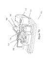
- FIG. 6is an isometric view of a lancing device in accordance with an embodiment of the present invention.
- FIGS. 7A to 7Hare a collection of isometric and top views showing the operation a lancing device in accordance with a preferred embodiment of the present invention.
- FIG. 8is a top view of a lancing device in accordance with an embodiment of the present invention.
- Lancing devices of the pasttypically have a lancet carrier (including a lancet) and a spring loaded lancet driver, mounted within a housing. As shown in FIG. 1C (FIG. 1 of U.S. Pat. No.
- these lancet devices 1101typically have a housing 1103 with an internal channel 1104 , a lancet 1106 having a needle 1105 connected to a lancet carrier 1113 , and a spring loaded lancet driver 1108 for driving the lancet carrier along the internal channel 1104 to the lancing end 1111 and bodily tissue 1112 .
- the devicesalso have a priming means for priming the lancet device and storing energy in lancet driver 1108 .
- the priming meansis priming handle 1110 .
- the lancet carrier 1113When a user pulls the handle 1110 along the internal channel 1104 and away from the lancing end 1111 of device 1101 , the lancet carrier 1113 is locked into a primed position where energy is stored in spring 1108 (i.e. the lancet driver). When a user presses release button 1114 , the energy stored in spring 1108 is released as the lancet carrier is driven along the internal channel 1104 toward the bodily tissue 1112 of a user.
- the present inventionprovides an improved lancing device that is user friendly and easy to prime.
- lancing devicestypically have a housing, an internal channel extending within the housing, a lancet carrier disposed in the internal channel, and a lancet driver.
- a userapplies force to a housing to prime the lancet carrier which is then placed into a primed position.
- the present inventionprovides an improvement to the lancing devices described above, the improvement comprises:
- first arm portion of the cantilevered priming arm(s)refers to the orientation of such with respect to the internal channel of the lancing device. At least part of the first arm portion is accessible by a user on the outside of the housing such that motion of the first arm portion toward the internal channel will be translated into priming motion of the lancet carrier along the strike path.
- the first arm portionwill be disposed exactly parallel to the internal channel. In other embodiments, at resting position, the first arm portion will be tipped toward or away from the internal channel by up to 45 degrees, for example 40 degrees, 35 degrees, 30 degrees, 25 degrees, 20 degrees, 15 degrees, 10 degrees, or 5 degrees.
- the term “generally perpendicular” as it is used herein with reference to the second arm portion of the cantilevered priming arm(s)refers to the orientation of such with respect to the internal channel of the device. Energy is translated from the movement of the first arm portion, around a pivot point, into movement of the second arm portion that draws the lancet carrier along the strike path toward a primed position.
- the second arm portionat resting position, is disposed exactly perpendicular (i.e. 90 degrees) to the internal channel.
- the second arm portionis disposed at a position that is 45 degrees away from perpendicular in either direction. For example 40 degrees, 35 degrees, 30 degrees, 25 degrees, 20 degrees, 15 degrees, 10 degrees, or 5 degrees away from perpendicular.
- connectionas it is used herein with reference to the second arm portion being “connected” to the lancet carrier is herein understood to mean that the second arm potion is in operative contact with the lancet carrier to draw the lancet carrier to a primed position when the first arm portion is moved toward the internal channel.
- the second arm portionmay be directly in contact with the lancet carrier or it may be indirectly in contact with the lancet carrier, for example through a shuttle.
- the second arm portionmay be in contact with the lancet carrier only when the first arm portion is moved toward the internal channel (e.g. upon priming the lancing device).
- the second arm portionis always in contact with (i.e. attached to) the lancet carrier.
- first and second arm portions of the cantilevered priming armare positioned relative to each other perpendicularly through a pivot point.
- the pivot pointbeing the point the first and second arm portions intersect and preferably the point at which the cantilevered priming arm moves relative to the housing.
- first and second arm portions of the cantilevered priming armare positioned relative to each other up to 45 degrees away from perpendicular in either direction through the pivot point. For example 40 degrees, 35 degrees, 30 degrees, 25 degrees, 20 degrees, 15 degrees, 10 degrees, or 5 degrees away from perpendicular.
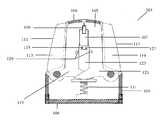
- FIG. 1Ashows a lancing device for lancing body tissue to result in a wound for bleeding in accordance with a preferred embodiment of the present invention.
- Lancing device 101comprises:
- FIG. 1Bshows the preferred lancing device described above with regard to FIG. 1A wherein the cantilever priming arms 111 , 117 are moved toward the internal channel of the device around pivot points 106 , 108 .
- the lancet carrier 107is drawn toward the primmed position.
- shuttle return spring 131is compressed.
- FIGS. 2A and 2Bshow cross-sectional top views of another embodiment of the present invention.
- a lancing device 201is shown comprising:
- FIG. 2Bshows the lancing device described in FIG. 2A wherein the cantilever priming arm 211 is moved toward the internal channel of the device around pivot point 206 . As the first portion 213 of the first cantilevered priming arm 211 is moved 233 toward the internal channel 205 , the lancet carrier 207 is drawn toward the primed position.
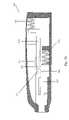
- FIGS. 3A , 3 B, and 3 Cshow a cross-sectional side views of the inner workings at different stages of priming and firing of a preferred device of the present invention.
- the deviceis designed such that cocking and firing are accomplished in a single movement of the cantilevered priming arms.
- FIG. 3Adepicts the lancet carrier 307 in a relaxed position.
- FIG. 3Bshows the device 301 as the lancet carrier 307 is drawn toward a primed position.
- FIG. 3Cshows the device 301 after it has been fired while the lancet carrier 307 is in a lancing position and prior to the release of the cantilevered priming arms.
- FIG. 3Ashows the device 301 while the lancet carrier is in resting position and prior to the release of the cantilevered priming arms.
- Device 301has, inter alia, a housing 303 , an internal channel 305 , a lancet carrier 307 , a shuttle 323 , a shuttle return spring 331 , and a lancet driver, spring 333 .
- the devicefurther comprises, a bump 351 disposed on either of the shuttle 323 or the housing 303 and a track 352 disposed on the other of the shuttle 323 or the housing 303 .
- bump 351is disposed on shuttle 323 and track 352 is disposed in interacting alignment in housing 303 .
- bump 351 and the track 352engage to tip the shuttle 323 as the lancet carrier 307 is drawn to the primed position.
- bump 351which is disposed on shuttle 323 rides along track 352 .
- Track 352is formed in the housing such that bump 351 is lifted as the lancet carrier draws near a primed position thereby lifting the shuttle 323 .
- the protrusion 325 and corresponding depression 327disengage thereby releasing energy stored in the lancet driver, spring 333 and firing the device 301 .
- Protrusion 325 and depression 327are designed such that they interact to draw the lancet carrier 307 toward a primed position, disengage to fire the device 301 , and re-engage upon release of the cantilevered priming arms for subsequent priming and firing of the device 301 .
- the protrusion 325may be formed on either of the lancet carrier 307 or the shuttle 323 , and the corresponding depression 327 may be formed on the other of the lancet carrier 307 or shuttle 323 .
- the protrusion 325is disposed on the lancet carrier 307 and is triangularly shaped having a flat priming surface.
- the depression 327also has a flat priming surface to engage flat priming surface of the protrusion 325 in priming alignment.
- the flat priming surface of the protrusion 325engages a flat priming surface of the depression 327 such that the lancet carrier 307 is drawn to a primed position without prematurely disengaging and prematurely firing the device 301 .
- the flat priming surface of the protrusion 325 and the flat priming surface of the depression 327will interact such that the plane of priming interaction will be perpendicular to the direction of the strike path.
- the lancet driver, spring 333also serves to return the lancet carrier 307 toward its resting position.
- the shuttle return spring 331(which is compressed by the shuttle 323 when the lancet carrier 307 is drawn to a primed position) drives the cantilevered priming arms toward their resting position and drives the shuttle 323 along the strike path toward the lancet carrier 307 , located in its resting position, to engage the protrusion 325 and corresponding depression 327 upon release of the cantilever priming arms.
- Protrusion 325is further shaped such that as the shuttle 323 returns toward the lancet carrier 307 , the shuttle 323 may ride up along a second slanted flat surface of the triangularly shaped protrusion 323 and fall into priming alignment as described above.
- FIGS. 4A , 4 B, and 4 Cshow a cross-sectional side views of the inner workings at different stages of priming and firing of another preferred device of the present invention.
- the deviceis designed such that cocking and firing are accomplished in a single movement of the cantilevered priming arms.
- FIG. 4Adepicts the lancet carrier 407 in a relaxed position.
- FIG. 4Bshows the device 401 as the lancet carrier 407 is drawn toward a primed position.
- FIG. 4Cshows the device 401 after it has been fired while the lancet carrier 407 is in a lancing position and prior to the release of the cantilevered priming arms.
- FIG. 4Ashows the device 401 while the lancet carrier is in resting position and prior to the release of the cantilevered priming arms.
- Device 401has, inter alia, a housing 403 , an internal channel 405 , a lancet carrier 407 , a shuttle 423 , a shuttle return spring 431 , a lancet driver, spring 433 , and a lancet return spring 435 .
- the devicefurther comprises, a bump 451 disposed on either of the shuttle 423 or the housing 403 and a track 452 disposed on the other of the shuttle 423 or the housing 403 .
- bump 451is disposed on shuttle 423 and track 452 is disposed in interacting alignment in housing 403 .
- bump 451 and the track 452engage to tip the shuttle 423 as the lancet carrier 407 is drawn to the primed position.
- bump 451which is disposed on shuttle 423 rides along track 452 .
- Track 452is formed in the housing such that bump 451 is lifted as the lancet carrier draws near a primed position thereby lifting the shuttle 423 .
- the protrusion 425 and corresponding depression 427disengage thereby releasing energy stored in the lancet driver, spring 433 and firing the device 401 .
- Protrusion 425 and depression 427are designed such that they interact to draw the lancet carrier 407 toward a primed position, disengage to fire the device 401 , and re-engage upon release of the cantilevered priming arms for subsequent priming and firing of the device 401 .
- the protrusion 425may be formed on either of the lancet carrier 407 or the shuttle 423 , and the corresponding depression 427 may be formed on the other of the lancet carrier 407 or shuttle 423 .
- the protrusion 425is disposed on the lancet carrier 407 and is triangularly shaped having a flat priming surface.
- the depression 427also has a flat priming surface to engage flat priming surface of the protrusion 425 in priming alignment.
- the flat priming surface of the protrusion 425engages a flat priming surface of the depression 427 such that the lancet carrier 407 is drawn to a primed position without prematurely disengaging and prematurely firing the device 401 .
- the flat priming surface of the protrusion 425 and the flat priming surface of the depression 427will interact such that the plane of priming interaction will be perpendicular to the direction of the strike path.
- the lancet return spring 435serves to return the lancet carrier 407 toward its resting position.
- the shuttle return spring 431(which is compressed by the shuttle 423 when the lancet carrier 407 is drawn to a primed position) drives the cantilevered priming arms toward their resting position and drives the shuttle 423 along the strike path toward the lancet carrier 407 , located in its resting position, to engage the protrusion 425 and corresponding depression 427 upon release of the cantilever priming arms.
- Protrusion 425is further shaped such that as the shuttle 423 returns toward the lancet carrier 407 , the shuttle 423 may ride up along a second slanted flat surface of the triangularly shaped protrusion 423 and fall into priming alignment as described above.
- the lancing device of the present inventionmay be designed such that priming and firing of the device occurs in two stages. For example, a user may prime the device by moving the cantilevered priming arm toward the internal channel of the device where the lancet carrier is placed into a locked and primed position and where energy is stored in the lancet driver. In a second step, a user may press a release button that releases the energy stored in the driver spring as the lancet carrier is driven along the strike path toward the skin the lancing end of the device.
- the lancet driveris shown as a coiled spring, which stores energy by being compressed.
- the inventionis not limited to the use of coiled springs and other structures capable of storing energy upon displacement by the action of the cantilevered priming arm are within the scope of the invention.
- the lancet drivermay be a leaf spring, an elastic band that is stretched or an elastomeric block that is compressed.
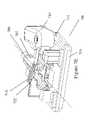
- FIGS. 6 , 7 A, 7 B, 7 C, 7 D, 7 E, 7 F, 7 G, and 7 Hillustrate another preferred lancing device in accordance with the present invention.
- FIG. 6illustrates an exploded view of a lancing device 601 having a first cantilevered priming arm 613 and housing 603 .
- the lancing devicehas an internal channel disposed within the housing 603 extending from a lancing end 604 to a second end 606 of the housing 603 .
- FIGS. 7A , 7 B, 7 C, 7 D, 7 E, 7 F, 7 G, and 7 Hillustrate the inner working of lancing device 601 (i.e. without housing top 603 ).
- lancing device 601 , 701 in FIGS. 6 , 7 A, 7 B, 7 C, 7 D, 7 E, 7 F, 7 G, and 7 His for use with a lancet 709 for lancing body tissue to result in a wound for bleeding.
- Lancing device 701comprises:
- FIGS. 7A , 7 B, 7 C, 7 D, 7 E, 7 F, 7 G, and 7 Hshow the lancing device 701 at different stages of operation.
- FIG. 7Ais an isometric view and FIG. 7B is a top view lancing device 701 in a resting position.
- second arm portion 715 of the first cantilevered priming arm 711is connected to (e.g. in operative contact with) with lancet carrier 707 at the priming protrusion 725 of the lancet carrier 707 .
- Lancing device 701also has a moveable firing ramp 752 that can be set by the user in either a safety position (as it is depicted in FIG. 7A and 7B ) or a fire position as depicted in FIGS.
- the firing ramp 752has been placed in the fire position.
- the lancet carrier 707is drawn closer to the primed position and the second arm portion 715 interacts with firing ramp 752 .
- FIGS. 7E (isometric view) and 7 F (top view) of the lancing device 701when placed in the fire position the firing ramp 752 serves to lift the second arm portion 715 and disengage the connection of the second arm portion 715 from the priming protrusion 725 of the lancet carrier 707 when the lancet carrier 707 reaches a primed position.
- the lancing device 701fires and energy stored in the lancet driver (not shown) is released thereby propelling the lancet carrier 707 and lancet 709 along the strike path to the lanced position depicted in FIGS. 7G (isometric view) and 7 H (top view).
- a tissue penetration portion 760 of lancet 709extend past the housing 703 for lancing interaction with a user's skin.
- the device 701may be reused.
- the used lancet 709is disposed of and a new lancet is used in each subsequent lancing.
- the priming ramp 752is moved to the safety position and the first arm portion 713 is moved 734 away from the internal channel whereby the second arm portion 715 is drawn toward priming protrusion 725 .
- Second arm portioninteracts with a slanted side 726 of priming protrusion 725 where the second arm portion 715 is lifted over the priming protrusion 725 and settles back into the resting position as depicted in FIGS.
- first arm portion 813has a return spring 853 associated with it where after a user releases the first arm portion 813 after lancing, the return spring 853 biases the first arm portion 813 toward the resting position, thereby returning the device 801 to the resting position after its use.
- the lancing devices depicted in any of FIGS. 6 through 8would further comprises a second cantilevered priming arm disposed on the opposing side of the internal channel.
- This second cantilevered armwould have mirrored operation (about the internal channel and the strike path) to the first cantilevered arm and would have similar interaction with the lancet carrier and a second firing ramp also disposed within the internal channel. In this latter embodiment, movement of the first arm portions of either or both of the cantilevered arms toward the internal channel would draw the lancet carrier toward a primed position.
- a lancet and an analyte monitoring meterare combined in a single device having a cantilevered priming arm described herein.
- the combinationallows for the reduction of the number of pieces of equipment required to perform an analyte measurement.
- the lancet housing described aboveprovides mounting locations for a lancet assembly having the cantilevered priming arm as well an analyte monitoring meter.
- the analyte monitoring metermay be formed integral with the lancet within the lancet housing or it may be detachable from the lancet housing to form a combined device.
- the combined devicewill have lancet features as described above and will include a housing, a display, a test strip interface, and a processor programmed to calculate and store the concentration of an analyte, preferably glucose, in a blood sample applied to a test strip.
- the housinghas an opening for receiving the meter display as well as an opening for receiving a diagnostic test strip inserted into the test strip interface of the analyte monitoring meter.
- the display opening and test strip opening of the housingmay be located anywhere along the housing, however, it is preferred that the display opening be on the side of the annular housing while the test strip opening be located at the lancing end of the housing.
- the analyte monitoring meter of the present inventionis not limited. However, the analyte monitoring meter described in U.S. patent publication No. US 2005/0265094, herein incorporated by reference, is particularly preferred.
- FIGS. 5A and 5Billustrate a combined lancet and analyte meter 501 of the present invention having cantilevered priming arms 511 , 517 for priming the lancet portion the device.
- the housing 503 of the combined device 501has a test strip opening 502 sized to receive a test strip 520 , a display opening 505 sized to receive a meter display 504 , and a lancet opening 506 sized to receive a tissue penetrating portion of a lancet.
- the analyte metercomprises a test strip interface for receiving a test strip; a processor programmed to perform a diagnostic test on a sample applied to a test strip received in the test strip interface to determine a concentration of an analyte within the sample; and the meter display 504 for displaying the result of the analyte measurement to the user.
- the processoris programed to determine the concentration of glucose within a blood sample.
Landscapes
- Health & Medical Sciences (AREA)
- Life Sciences & Earth Sciences (AREA)
- Heart & Thoracic Surgery (AREA)
- Medical Informatics (AREA)
- Biophysics (AREA)
- Pathology (AREA)
- Engineering & Computer Science (AREA)
- Biomedical Technology (AREA)
- Hematology (AREA)
- Physics & Mathematics (AREA)
- Molecular Biology (AREA)
- Surgery (AREA)
- Animal Behavior & Ethology (AREA)
- General Health & Medical Sciences (AREA)
- Public Health (AREA)
- Veterinary Medicine (AREA)
- Dermatology (AREA)
- Measurement Of The Respiration, Hearing Ability, Form, And Blood Characteristics Of Living Organisms (AREA)
Abstract
Description
- (a) a housing having an internal channel extending within the housing from a first lancing end toward a second end of the housing;
- (b) a lancet carrier translationally mounted within the internal channel for carrying a lancet along a strike path of the lancet carrier, said strike path starting at a primed position toward the second end of the housing and extending to a lanced position at the first lancing end of the housing,
- (c) a lancet driver for storing energy and then driving the lancet carrier along the strike path from the primed position to the lanced position; and
- (d) a first cantilevered priming arm comprising a first arm portion that is generally parallel to the internal channel and a second arm portion that is generally perpendicular to the internal channel, wherein the second arm portion is connected to the lancet carrier,
wherein movement of the first arm portion toward the internal channel draws the lancet carrier to a primed position and stores energy in the lancet driver.
- a cantilevered priming arm comprising a first arm portion that is generally parallel to the internal channel and a second arm portion that is generally perpendicular to the internal channel, wherein the second arm portion is connected to the lancet carrier, wherein movement of the first arm portion toward the internal channel draws the lancet carrier to a primed position and stores energy in the lancet driver.
- (a) a
housing 103 having aninternal channel 105 extending within thehousing 103 from a firstlancing end 104 toward a second end of thehousing 106; - (b) a
lancet carrier 107 translationally mounted within theinternal channel 105 for carrying alancet 109 along a strike path of thelancet carrier 107, said strike path starting at a primed position toward thesecond end 106 of thehousing 103 and extending to a lanced position at the first lancingend 104 of thehousing 103, - (c) a lancet driver in the form of a spring (shown in
FIGS. 3A ,3B,3C,4A,4B, and4C) for storing energy and then driving the lancet carrier along the strike path from the primed position to the lanced position; and - (d) a first cantilevered
priming arm 111 comprising afirst arm portion 113 that is generally parallel to theinternal channel 105 and asecond arm portion 115 that is generally perpendicular to the internal channel, wherein thesecond arm portion 115 is connected to thelancet carrier 107, - (e) a second cantilevered priming
arm 117 comprising afirst arm portion 119 that is generally parallel to theinternal channel 105 and asecond arm portion 121 that is generally perpendicular to theinternal channel 105, said first111 and second117 cantilevered priming arms being disposed on opposing sides of theinternal channel 105, - (f) a
shuttle 123 disposed within theinternal channel 105, wherein theshuttle 123 connects the first111 and second117 cantilevered priming arms to thelancet carrier 107, saidshuttle 123 andlancet carrier 107 comprising aprotrusion 125 and corresponddepression 127 that engage to draw thelancet carrier 107 to a primed position and that release to fire the device101 (InFIG. 1A protrusion 125 is disposed on thelancet carrier 107 whiledepression 127 is made in shuttle123); - (g) a bump129 (
bumps 129 shown inFIG. 1A ) disposed on either of theshuttle 123 or thehousing 103 and a track (shown inFIGS. 3A ,3B,3C,4A,4B, and4C) disposed on the other of theshuttle 123 or thehousing 103, saidbump 129 and said track engage to tip theshuttle 123 as thelancet carrier 107 is drawn to the primed position, such that after thelancet carrier 107 reaches the primed position theprotrusion 125 andcorresponding depression 127 disengage thereby releasing energy stored in the lancet driver and firing thedevice 101, - (h) a lancet carrier return spring (shown in
FIGS. 4A ,4B,4C) that interacts with thelancet carrier 107 to return thelancet carrier 107 to a resting position within theinternal channel 105 after thedevice 101 is fired, - (i) a
shuttle return spring 131 compressed by theshuttle 123 when thelancet carrier 107 is drawn toward the primed position, saidshuttle return spring 131 drives thecantilever arms FIG. 1A ) and drives theshuttle 123 along the strike path toward thelancet carrier 107 located in a resting position to engage theprotrusion 125 andcorresponding depression 127 upon release of thecantilever priming arms - (j) a
lancet 109 disposed within thelancet carrier 107,
wherein movement of thefirst arm portions lancet carrier 107 toward the primed position and stores energy in the lancet driver.
- (a) a
- (a) a
housing 203 having aninternal channel 205 extending within thehousing 203 from afirst lancing 204 end toward asecond end 206 of thehousing 203; - (b) a
lancet carrier 207 translationally mounted within theinternal channel 205 for carrying alancet 209 along a strike path of thelancet carrier 207, said strike path starting at a primed position toward thesecond end 206 of thehousing 203 and extending to a lanced position at the first lancingend 204 of thehousing 203, - (c) a lancet driver in the form of a spring (shown in
FIGS. 3A ,3B,3C,4A,4B, and4C) for storing energy and then driving thelancet carrier 207 along the strike path from the primed position to the lanced position; and - (d) a first cantilevered
priming arm 211 comprising afirst arm portion 213 that is generally parallel to theinternal channel 205 and asecond arm portion 215 that is generally perpendicular to theinternal channel 205, wherein thesecond arm portion 215 is connected to thelancet carrier 207,
wherein movement of thefirst arm portion 211 toward theinternal channel 205 draws thelancet carrier 207 to a primed position and stores energy in the lancet driver.
- (a) a
- (a) a
housing 603,703 (housing top 603 shown inFIG. 6 ) having an internal channel extending within thehousing second end 606 of thehousing - (b) a
lancet carrier 707 translationally mounted within the internal channel for carrying alancet 709 along astrike path 750 of thelancet carrier 707, saidstrike path 750 starting at a primed position toward thesecond end 606 of the housing and extending to a lanced position at the first lancing end of the housing604, - (c) a lancet driver (not shown in
FIGS. 6 ,7A,7B,7C,7D,7E,7F,7G, and7H) for storing energy and then driving thelancet carrier 707 along thestrike path 750 from the primed position to the lanced position; and - (d) a first cantilevered
priming arm 711 comprising afirst arm portion 713 that is generally parallel to the internal channel and asecond arm portion 715 that is generally perpendicular to the internal channel, wherein thesecond arm portion 715 is connected to thelancet carrier 707,
wherein movement of thefirst arm portion 713 toward the internal channel draws thelancet carrier 707 to a primed position and stores energy in the lancet driver.
- (a) a
Claims (21)
Priority Applications (1)
| Application Number | Priority Date | Filing Date | Title |
|---|---|---|---|
| US11/733,032US8162968B2 (en) | 2006-04-10 | 2007-04-09 | Lancing device |
Applications Claiming Priority (2)
| Application Number | Priority Date | Filing Date | Title |
|---|---|---|---|
| US74456006P | 2006-04-10 | 2006-04-10 | |
| US11/733,032US8162968B2 (en) | 2006-04-10 | 2007-04-09 | Lancing device |
Publications (2)
| Publication Number | Publication Date |
|---|---|
| US20070239188A1 US20070239188A1 (en) | 2007-10-11 |
| US8162968B2true US8162968B2 (en) | 2012-04-24 |
Family
ID=38581468
Family Applications (1)
| Application Number | Title | Priority Date | Filing Date |
|---|---|---|---|
| US11/733,032Active2030-03-07US8162968B2 (en) | 2006-04-10 | 2007-04-09 | Lancing device |
Country Status (4)
| Country | Link |
|---|---|
| US (1) | US8162968B2 (en) |
| EP (1) | EP2004058B1 (en) |
| ES (1) | ES2429907T3 (en) |
| WO (1) | WO2007116367A2 (en) |
Cited By (29)
| Publication number | Priority date | Publication date | Assignee | Title |
|---|---|---|---|---|
| US20060161194A1 (en)* | 2003-06-11 | 2006-07-20 | Freeman Dominique M | Low pain penetrating member |
| US20070123802A1 (en)* | 2002-09-05 | 2007-05-31 | Freeman Dominique M | Methods and apparatus for an analyte detecting device |
| US20070219463A1 (en)* | 2002-04-19 | 2007-09-20 | Barry Briggs | Methods and apparatus for lancet actuation |
| US20080021491A1 (en)* | 2002-04-19 | 2008-01-24 | Freeman Dominique M | Method and apparatus for penetrating tissue |
| US20080027385A1 (en)* | 2002-04-19 | 2008-01-31 | Freeman Dominique M | Method and apparatus for penetrating tissue |
| US20090029169A1 (en)* | 2007-07-27 | 2009-01-29 | Fujifilm Corporation | Composition, article and their production method, and film and its production method |
| US20090131964A1 (en)* | 2002-04-19 | 2009-05-21 | Dominique Freeman | Tissue penetration device |
| US20100292611A1 (en)* | 2003-12-31 | 2010-11-18 | Paul Lum | Method and apparatus for improving fluidic flow and sample capture |
| US20120271123A1 (en)* | 2010-06-09 | 2012-10-25 | Mark Castle | Integrated lancing device |
| US8382683B2 (en) | 2001-06-12 | 2013-02-26 | Sanofi-Aventis Deutschland Gmbh | Tissue penetration device |
| US8403864B2 (en) | 2002-04-19 | 2013-03-26 | Sanofi-Aventis Deutschland Gmbh | Method and apparatus for penetrating tissue |
| US8574895B2 (en) | 2002-12-30 | 2013-11-05 | Sanofi-Aventis Deutschland Gmbh | Method and apparatus using optical techniques to measure analyte levels |
| US8641644B2 (en) | 2000-11-21 | 2014-02-04 | Sanofi-Aventis Deutschland Gmbh | Blood testing apparatus having a rotatable cartridge with multiple lancing elements and testing means |
| US8652831B2 (en) | 2004-12-30 | 2014-02-18 | Sanofi-Aventis Deutschland Gmbh | Method and apparatus for analyte measurement test time |
| US8702624B2 (en) | 2006-09-29 | 2014-04-22 | Sanofi-Aventis Deutschland Gmbh | Analyte measurement device with a single shot actuator |
| US8721671B2 (en) | 2001-06-12 | 2014-05-13 | Sanofi-Aventis Deutschland Gmbh | Electric lancet actuator |
| US8784335B2 (en) | 2002-04-19 | 2014-07-22 | Sanofi-Aventis Deutschland Gmbh | Body fluid sampling device with a capacitive sensor |
| US8828203B2 (en) | 2004-05-20 | 2014-09-09 | Sanofi-Aventis Deutschland Gmbh | Printable hydrogels for biosensors |
| US8945910B2 (en) | 2003-09-29 | 2015-02-03 | Sanofi-Aventis Deutschland Gmbh | Method and apparatus for an improved sample capture device |
| US8965476B2 (en) | 2010-04-16 | 2015-02-24 | Sanofi-Aventis Deutschland Gmbh | Tissue penetration device |
| US9226699B2 (en) | 2002-04-19 | 2016-01-05 | Sanofi-Aventis Deutschland Gmbh | Body fluid sampling module with a continuous compression tissue interface surface |
| US9248267B2 (en) | 2002-04-19 | 2016-02-02 | Sanofi-Aventis Deustchland Gmbh | Tissue penetration device |
| US9314194B2 (en) | 2002-04-19 | 2016-04-19 | Sanofi-Aventis Deutschland Gmbh | Tissue penetration device |
| US9351680B2 (en) | 2003-10-14 | 2016-05-31 | Sanofi-Aventis Deutschland Gmbh | Method and apparatus for a variable user interface |
| US9375169B2 (en) | 2009-01-30 | 2016-06-28 | Sanofi-Aventis Deutschland Gmbh | Cam drive for managing disposable penetrating member actions with a single motor and motor and control system |
| US9427532B2 (en) | 2001-06-12 | 2016-08-30 | Sanofi-Aventis Deutschland Gmbh | Tissue penetration device |
| US9775553B2 (en) | 2004-06-03 | 2017-10-03 | Sanofi-Aventis Deutschland Gmbh | Method and apparatus for a fluid sampling device |
| US9795747B2 (en) | 2010-06-02 | 2017-10-24 | Sanofi-Aventis Deutschland Gmbh | Methods and apparatus for lancet actuation |
| US9820684B2 (en) | 2004-06-03 | 2017-11-21 | Sanofi-Aventis Deutschland Gmbh | Method and apparatus for a fluid sampling device |
Families Citing this family (26)
| Publication number | Priority date | Publication date | Assignee | Title |
|---|---|---|---|---|
| US6391005B1 (en) | 1998-03-30 | 2002-05-21 | Agilent Technologies, Inc. | Apparatus and method for penetration with shaft having a sensor for sensing penetration depth |
| US7981056B2 (en) | 2002-04-19 | 2011-07-19 | Pelikan Technologies, Inc. | Methods and apparatus for lancet actuation |
| US8337419B2 (en) | 2002-04-19 | 2012-12-25 | Sanofi-Aventis Deutschland Gmbh | Tissue penetration device |
| JP4209767B2 (en) | 2001-06-12 | 2009-01-14 | ペリカン テクノロジーズ インコーポレイテッド | Self-optimized cutting instrument with adaptive means for temporary changes in skin properties |
| US7749174B2 (en) | 2001-06-12 | 2010-07-06 | Pelikan Technologies, Inc. | Method and apparatus for lancet launching device intergrated onto a blood-sampling cartridge |
| US7674232B2 (en) | 2002-04-19 | 2010-03-09 | Pelikan Technologies, Inc. | Method and apparatus for penetrating tissue |
| US8221334B2 (en) | 2002-04-19 | 2012-07-17 | Sanofi-Aventis Deutschland Gmbh | Method and apparatus for penetrating tissue |
| US7491178B2 (en) | 2002-04-19 | 2009-02-17 | Pelikan Technologies, Inc. | Method and apparatus for penetrating tissue |
| US8360992B2 (en) | 2002-04-19 | 2013-01-29 | Sanofi-Aventis Deutschland Gmbh | Method and apparatus for penetrating tissue |
| US7331931B2 (en) | 2002-04-19 | 2008-02-19 | Pelikan Technologies, Inc. | Method and apparatus for penetrating tissue |
| US7297122B2 (en) | 2002-04-19 | 2007-11-20 | Pelikan Technologies, Inc. | Method and apparatus for penetrating tissue |
| US7229458B2 (en) | 2002-04-19 | 2007-06-12 | Pelikan Technologies, Inc. | Method and apparatus for penetrating tissue |
| US8267870B2 (en) | 2002-04-19 | 2012-09-18 | Sanofi-Aventis Deutschland Gmbh | Method and apparatus for body fluid sampling with hybrid actuation |
| US7909778B2 (en) | 2002-04-19 | 2011-03-22 | Pelikan Technologies, Inc. | Method and apparatus for penetrating tissue |
| US8372016B2 (en) | 2002-04-19 | 2013-02-12 | Sanofi-Aventis Deutschland Gmbh | Method and apparatus for body fluid sampling and analyte sensing |
| US7232451B2 (en) | 2002-04-19 | 2007-06-19 | Pelikan Technologies, Inc. | Method and apparatus for penetrating tissue |
| US7901362B2 (en) | 2002-04-19 | 2011-03-08 | Pelikan Technologies, Inc. | Method and apparatus for penetrating tissue |
| US7892183B2 (en) | 2002-04-19 | 2011-02-22 | Pelikan Technologies, Inc. | Method and apparatus for body fluid sampling and analyte sensing |
| US7976476B2 (en) | 2002-04-19 | 2011-07-12 | Pelikan Technologies, Inc. | Device and method for variable speed lancet |
| DE602004028463D1 (en) | 2003-05-30 | 2010-09-16 | Pelikan Technologies Inc | METHOD AND DEVICE FOR INJECTING LIQUID |
| US7850621B2 (en) | 2003-06-06 | 2010-12-14 | Pelikan Technologies, Inc. | Method and apparatus for body fluid sampling and analyte sensing |
| US7822454B1 (en) | 2005-01-03 | 2010-10-26 | Pelikan Technologies, Inc. | Fluid sampling device with improved analyte detecting member configuration |
| US8652166B2 (en) | 2007-11-30 | 2014-02-18 | Radi Medical Systems Ab | Insertion tool for a medical closure device |
| EP2265324B1 (en) | 2008-04-11 | 2015-01-28 | Sanofi-Aventis Deutschland GmbH | Integrated analyte measurement system |
| US20100198107A1 (en)* | 2009-01-30 | 2010-08-05 | Roche Diagnostics Operations, Inc. | Integrated blood glucose meter and lancing device |
| EP4302691A3 (en)* | 2019-06-05 | 2024-03-13 | Owen Mumford Limited | Lancing device |
Citations (20)
| Publication number | Priority date | Publication date | Assignee | Title |
|---|---|---|---|---|
| US3030959A (en)* | 1959-09-04 | 1962-04-24 | Praemeta | Surgical lancet for blood sampling |
| US3200792A (en)* | 1963-05-31 | 1965-08-17 | Nathan A Zepell | Writing instrument |
| US4627445A (en) | 1985-04-08 | 1986-12-09 | Garid, Inc. | Glucose medical monitoring system |
| US4790678A (en)* | 1986-06-25 | 1988-12-13 | Pilot Ink Co., Ltd. | Mechanism for extruding and retracting a writing member of a writing instrument |
| US6053930A (en) | 1998-05-11 | 2000-04-25 | Ruppert; Norbert | Single use lancet assembly |
| US6192891B1 (en)* | 1999-04-26 | 2001-02-27 | Becton Dickinson And Company | Integrated system including medication delivery pen, blood monitoring device, and lancer |
| US6210420B1 (en)* | 1999-01-19 | 2001-04-03 | Agilent Technologies, Inc. | Apparatus and method for efficient blood sampling with lancet |
| JP2002085384A (en) | 2000-09-12 | 2002-03-26 | Terumo Corp | Tip for component measuring device and component measuring device and system |
| US6479618B1 (en) | 1998-12-10 | 2002-11-12 | Cognis Deutschland Gmbh | Enzymatic esterification |
| US6533797B1 (en)* | 1999-11-24 | 2003-03-18 | Nuvasive | Control grip assembly |
| US20030199912A1 (en)* | 2002-04-23 | 2003-10-23 | Pugh Jerry T. | Lancing device with automatic stick and return |
| US6719771B1 (en) | 1999-06-19 | 2004-04-13 | Owen Mumford Limited | Blood sampling device |
| US6729785B2 (en)* | 2002-08-06 | 2004-05-04 | Rose Art Industries, Inc. | Method and device for advancing a lead and an eraser in a mechanical pencil and for advancing a pen and an eraser in a pen |
| US6840912B2 (en) | 2001-12-07 | 2005-01-11 | Micronix, Inc | Consolidated body fluid testing device and method |
| US6852119B1 (en) | 2002-09-09 | 2005-02-08 | Ramzi F. Abulhaj | Adjustable disposable lancet and method |
| US6866641B2 (en) | 2000-11-28 | 2005-03-15 | Owen Mumford Limited | Skin prickers |
| US20050265094A1 (en) | 2004-05-30 | 2005-12-01 | Agamatrix, Inc. | Measuring device and methods for use therewith |
| US20060155210A1 (en)* | 2005-01-10 | 2006-07-13 | Ethicon Endo-Surgery, Inc. | Biopsy instrument with improved needle penetration |
| US20060200181A1 (en)* | 2003-04-11 | 2006-09-07 | Arkray, Inc. | Needle insertion device |
| US20060241666A1 (en)* | 2003-06-11 | 2006-10-26 | Briggs Barry D | Method and apparatus for body fluid sampling and analyte sensing |
Family Cites Families (1)
| Publication number | Priority date | Publication date | Assignee | Title |
|---|---|---|---|---|
| US7604118B2 (en)* | 2003-12-15 | 2009-10-20 | Panasonic Corporation | Puncture needle cartridge and lancet for blood collection |
- 2007
- 2007-04-09USUS11/733,032patent/US8162968B2/enactiveActive
- 2007-04-10EPEP07735429.8Apatent/EP2004058B1/enactiveActive
- 2007-04-10ESES07735429Tpatent/ES2429907T3/enactiveActive
- 2007-04-10WOPCT/IB2007/051260patent/WO2007116367A2/enactiveApplication Filing
Patent Citations (20)
| Publication number | Priority date | Publication date | Assignee | Title |
|---|---|---|---|---|
| US3030959A (en)* | 1959-09-04 | 1962-04-24 | Praemeta | Surgical lancet for blood sampling |
| US3200792A (en)* | 1963-05-31 | 1965-08-17 | Nathan A Zepell | Writing instrument |
| US4627445A (en) | 1985-04-08 | 1986-12-09 | Garid, Inc. | Glucose medical monitoring system |
| US4790678A (en)* | 1986-06-25 | 1988-12-13 | Pilot Ink Co., Ltd. | Mechanism for extruding and retracting a writing member of a writing instrument |
| US6053930A (en) | 1998-05-11 | 2000-04-25 | Ruppert; Norbert | Single use lancet assembly |
| US6479618B1 (en) | 1998-12-10 | 2002-11-12 | Cognis Deutschland Gmbh | Enzymatic esterification |
| US6210420B1 (en)* | 1999-01-19 | 2001-04-03 | Agilent Technologies, Inc. | Apparatus and method for efficient blood sampling with lancet |
| US6192891B1 (en)* | 1999-04-26 | 2001-02-27 | Becton Dickinson And Company | Integrated system including medication delivery pen, blood monitoring device, and lancer |
| US6719771B1 (en) | 1999-06-19 | 2004-04-13 | Owen Mumford Limited | Blood sampling device |
| US6533797B1 (en)* | 1999-11-24 | 2003-03-18 | Nuvasive | Control grip assembly |
| JP2002085384A (en) | 2000-09-12 | 2002-03-26 | Terumo Corp | Tip for component measuring device and component measuring device and system |
| US6866641B2 (en) | 2000-11-28 | 2005-03-15 | Owen Mumford Limited | Skin prickers |
| US6840912B2 (en) | 2001-12-07 | 2005-01-11 | Micronix, Inc | Consolidated body fluid testing device and method |
| US20030199912A1 (en)* | 2002-04-23 | 2003-10-23 | Pugh Jerry T. | Lancing device with automatic stick and return |
| US6729785B2 (en)* | 2002-08-06 | 2004-05-04 | Rose Art Industries, Inc. | Method and device for advancing a lead and an eraser in a mechanical pencil and for advancing a pen and an eraser in a pen |
| US6852119B1 (en) | 2002-09-09 | 2005-02-08 | Ramzi F. Abulhaj | Adjustable disposable lancet and method |
| US20060200181A1 (en)* | 2003-04-11 | 2006-09-07 | Arkray, Inc. | Needle insertion device |
| US20060241666A1 (en)* | 2003-06-11 | 2006-10-26 | Briggs Barry D | Method and apparatus for body fluid sampling and analyte sensing |
| US20050265094A1 (en) | 2004-05-30 | 2005-12-01 | Agamatrix, Inc. | Measuring device and methods for use therewith |
| US20060155210A1 (en)* | 2005-01-10 | 2006-07-13 | Ethicon Endo-Surgery, Inc. | Biopsy instrument with improved needle penetration |
Cited By (66)
| Publication number | Priority date | Publication date | Assignee | Title |
|---|---|---|---|---|
| US8641644B2 (en) | 2000-11-21 | 2014-02-04 | Sanofi-Aventis Deutschland Gmbh | Blood testing apparatus having a rotatable cartridge with multiple lancing elements and testing means |
| US8622930B2 (en) | 2001-06-12 | 2014-01-07 | Sanofi-Aventis Deutschland Gmbh | Tissue penetration device |
| US9937298B2 (en) | 2001-06-12 | 2018-04-10 | Sanofi-Aventis Deutschland Gmbh | Tissue penetration device |
| US9802007B2 (en) | 2001-06-12 | 2017-10-31 | Sanofi-Aventis Deutschland Gmbh | Methods and apparatus for lancet actuation |
| US9694144B2 (en) | 2001-06-12 | 2017-07-04 | Sanofi-Aventis Deutschland Gmbh | Sampling module device and method |
| US9427532B2 (en) | 2001-06-12 | 2016-08-30 | Sanofi-Aventis Deutschland Gmbh | Tissue penetration device |
| US8845550B2 (en) | 2001-06-12 | 2014-09-30 | Sanofi-Aventis Deutschland Gmbh | Tissue penetration device |
| US8721671B2 (en) | 2001-06-12 | 2014-05-13 | Sanofi-Aventis Deutschland Gmbh | Electric lancet actuator |
| US8679033B2 (en) | 2001-06-12 | 2014-03-25 | Sanofi-Aventis Deutschland Gmbh | Tissue penetration device |
| US8641643B2 (en) | 2001-06-12 | 2014-02-04 | Sanofi-Aventis Deutschland Gmbh | Sampling module device and method |
| US8382683B2 (en) | 2001-06-12 | 2013-02-26 | Sanofi-Aventis Deutschland Gmbh | Tissue penetration device |
| US9560993B2 (en) | 2001-11-21 | 2017-02-07 | Sanofi-Aventis Deutschland Gmbh | Blood testing apparatus having a rotatable cartridge with multiple lancing elements and testing means |
| US8808201B2 (en) | 2002-04-19 | 2014-08-19 | Sanofi-Aventis Deutschland Gmbh | Methods and apparatus for penetrating tissue |
| US9498160B2 (en) | 2002-04-19 | 2016-11-22 | Sanofi-Aventis Deutschland Gmbh | Method for penetrating tissue |
| US8496601B2 (en) | 2002-04-19 | 2013-07-30 | Sanofi-Aventis Deutschland Gmbh | Methods and apparatus for lancet actuation |
| US8556829B2 (en) | 2002-04-19 | 2013-10-15 | Sanofi-Aventis Deutschland Gmbh | Method and apparatus for penetrating tissue |
| US8562545B2 (en) | 2002-04-19 | 2013-10-22 | Sanofi-Aventis Deutschland Gmbh | Tissue penetration device |
| US8574168B2 (en) | 2002-04-19 | 2013-11-05 | Sanofi-Aventis Deutschland Gmbh | Method and apparatus for a multi-use body fluid sampling device with analyte sensing |
| US9907502B2 (en) | 2002-04-19 | 2018-03-06 | Sanofi-Aventis Deutschland Gmbh | Method and apparatus for penetrating tissue |
| US8579831B2 (en) | 2002-04-19 | 2013-11-12 | Sanofi-Aventis Deutschland Gmbh | Method and apparatus for penetrating tissue |
| US8403864B2 (en) | 2002-04-19 | 2013-03-26 | Sanofi-Aventis Deutschland Gmbh | Method and apparatus for penetrating tissue |
| US8636673B2 (en) | 2002-04-19 | 2014-01-28 | Sanofi-Aventis Deutschland Gmbh | Tissue penetration device |
| US9839386B2 (en) | 2002-04-19 | 2017-12-12 | Sanofi-Aventis Deustschland Gmbh | Body fluid sampling device with capacitive sensor |
| US20070219463A1 (en)* | 2002-04-19 | 2007-09-20 | Barry Briggs | Methods and apparatus for lancet actuation |
| US9795334B2 (en) | 2002-04-19 | 2017-10-24 | Sanofi-Aventis Deutschland Gmbh | Method and apparatus for penetrating tissue |
| US9724021B2 (en) | 2002-04-19 | 2017-08-08 | Sanofi-Aventis Deutschland Gmbh | Method and apparatus for penetrating tissue |
| US20070219462A1 (en)* | 2002-04-19 | 2007-09-20 | Barry Briggs | Methods and apparatus for lancet actuation |
| US8690796B2 (en) | 2002-04-19 | 2014-04-08 | Sanofi-Aventis Deutschland Gmbh | Method and apparatus for penetrating tissue |
| US20080021491A1 (en)* | 2002-04-19 | 2008-01-24 | Freeman Dominique M | Method and apparatus for penetrating tissue |
| US20090131964A1 (en)* | 2002-04-19 | 2009-05-21 | Dominique Freeman | Tissue penetration device |
| US8784335B2 (en) | 2002-04-19 | 2014-07-22 | Sanofi-Aventis Deutschland Gmbh | Body fluid sampling device with a capacitive sensor |
| US8491500B2 (en) | 2002-04-19 | 2013-07-23 | Sanofi-Aventis Deutschland Gmbh | Methods and apparatus for lancet actuation |
| US20080027385A1 (en)* | 2002-04-19 | 2008-01-31 | Freeman Dominique M | Method and apparatus for penetrating tissue |
| US9339612B2 (en) | 2002-04-19 | 2016-05-17 | Sanofi-Aventis Deutschland Gmbh | Tissue penetration device |
| US8845549B2 (en) | 2002-04-19 | 2014-09-30 | Sanofi-Aventis Deutschland Gmbh | Method for penetrating tissue |
| US8905945B2 (en) | 2002-04-19 | 2014-12-09 | Dominique M. Freeman | Method and apparatus for penetrating tissue |
| US9314194B2 (en) | 2002-04-19 | 2016-04-19 | Sanofi-Aventis Deutschland Gmbh | Tissue penetration device |
| US9248267B2 (en) | 2002-04-19 | 2016-02-02 | Sanofi-Aventis Deustchland Gmbh | Tissue penetration device |
| US9226699B2 (en) | 2002-04-19 | 2016-01-05 | Sanofi-Aventis Deutschland Gmbh | Body fluid sampling module with a continuous compression tissue interface surface |
| US9072842B2 (en) | 2002-04-19 | 2015-07-07 | Sanofi-Aventis Deutschland Gmbh | Method and apparatus for penetrating tissue |
| US9089294B2 (en) | 2002-04-19 | 2015-07-28 | Sanofi-Aventis Deutschland Gmbh | Analyte measurement device with a single shot actuator |
| US9089678B2 (en) | 2002-04-19 | 2015-07-28 | Sanofi-Aventis Deutschland Gmbh | Method and apparatus for penetrating tissue |
| US9186468B2 (en) | 2002-04-19 | 2015-11-17 | Sanofi-Aventis Deutschland Gmbh | Method and apparatus for penetrating tissue |
| US20110034829A9 (en)* | 2002-09-05 | 2011-02-10 | Freeman Dominique M | Methods and apparatus for an analyte detecting device |
| US20070123802A1 (en)* | 2002-09-05 | 2007-05-31 | Freeman Dominique M | Methods and apparatus for an analyte detecting device |
| US9034639B2 (en) | 2002-12-30 | 2015-05-19 | Sanofi-Aventis Deutschland Gmbh | Method and apparatus using optical techniques to measure analyte levels |
| US8574895B2 (en) | 2002-12-30 | 2013-11-05 | Sanofi-Aventis Deutschland Gmbh | Method and apparatus using optical techniques to measure analyte levels |
| US20060161194A1 (en)* | 2003-06-11 | 2006-07-20 | Freeman Dominique M | Low pain penetrating member |
| US10034628B2 (en) | 2003-06-11 | 2018-07-31 | Sanofi-Aventis Deutschland Gmbh | Low pain penetrating member |
| US9144401B2 (en) | 2003-06-11 | 2015-09-29 | Sanofi-Aventis Deutschland Gmbh | Low pain penetrating member |
| US8945910B2 (en) | 2003-09-29 | 2015-02-03 | Sanofi-Aventis Deutschland Gmbh | Method and apparatus for an improved sample capture device |
| US9351680B2 (en) | 2003-10-14 | 2016-05-31 | Sanofi-Aventis Deutschland Gmbh | Method and apparatus for a variable user interface |
| US20100292611A1 (en)* | 2003-12-31 | 2010-11-18 | Paul Lum | Method and apparatus for improving fluidic flow and sample capture |
| US9561000B2 (en) | 2003-12-31 | 2017-02-07 | Sanofi-Aventis Deutschland Gmbh | Method and apparatus for improving fluidic flow and sample capture |
| US8668656B2 (en) | 2003-12-31 | 2014-03-11 | Sanofi-Aventis Deutschland Gmbh | Method and apparatus for improving fluidic flow and sample capture |
| US8828203B2 (en) | 2004-05-20 | 2014-09-09 | Sanofi-Aventis Deutschland Gmbh | Printable hydrogels for biosensors |
| US9261476B2 (en) | 2004-05-20 | 2016-02-16 | Sanofi Sa | Printable hydrogel for biosensors |
| US9820684B2 (en) | 2004-06-03 | 2017-11-21 | Sanofi-Aventis Deutschland Gmbh | Method and apparatus for a fluid sampling device |
| US9775553B2 (en) | 2004-06-03 | 2017-10-03 | Sanofi-Aventis Deutschland Gmbh | Method and apparatus for a fluid sampling device |
| US8652831B2 (en) | 2004-12-30 | 2014-02-18 | Sanofi-Aventis Deutschland Gmbh | Method and apparatus for analyte measurement test time |
| US8702624B2 (en) | 2006-09-29 | 2014-04-22 | Sanofi-Aventis Deutschland Gmbh | Analyte measurement device with a single shot actuator |
| US20090029169A1 (en)* | 2007-07-27 | 2009-01-29 | Fujifilm Corporation | Composition, article and their production method, and film and its production method |
| US9375169B2 (en) | 2009-01-30 | 2016-06-28 | Sanofi-Aventis Deutschland Gmbh | Cam drive for managing disposable penetrating member actions with a single motor and motor and control system |
| US8965476B2 (en) | 2010-04-16 | 2015-02-24 | Sanofi-Aventis Deutschland Gmbh | Tissue penetration device |
| US9795747B2 (en) | 2010-06-02 | 2017-10-24 | Sanofi-Aventis Deutschland Gmbh | Methods and apparatus for lancet actuation |
| US20120271123A1 (en)* | 2010-06-09 | 2012-10-25 | Mark Castle | Integrated lancing device |
Also Published As
| Publication number | Publication date |
|---|---|
| WO2007116367A2 (en) | 2007-10-18 |
| ES2429907T3 (en) | 2013-11-18 |
| EP2004058A4 (en) | 2012-06-20 |
| EP2004058A2 (en) | 2008-12-24 |
| EP2004058B1 (en) | 2013-08-21 |
| US20070239188A1 (en) | 2007-10-11 |
| WO2007116367A3 (en) | 2007-12-27 |
Similar Documents
| Publication | Publication Date | Title |
|---|---|---|
| US8162968B2 (en) | Lancing device | |
| US7438694B2 (en) | Lancing device | |
| CN1981702B (en) | Analyte monitoring system with integrated lancing apparatus | |
| US7691117B2 (en) | Lancing device | |
| EP1163879B1 (en) | Lancing mechanism | |
| US6929649B2 (en) | Lancing device with automatic stick and return | |
| TWI374728B (en) | Lancing device with a floating probe for control of penetration depth | |
| CN100401982C (en) | blood pumping device | |
| ES2375256T3 (en) | CONTACT ACTIVATED LANCETA DEVICE. | |
| US7927345B2 (en) | Lancet cartridges and lancing devices | |
| US20070100364A1 (en) | Compact lancing apparatus | |
| CN201303942Y (en) | Skin pricking device | |
| US20070010841A1 (en) | Lancet assembly | |
| CN1964667B (en) | Squeeze-activated medical puncturing device | |
| US8920342B2 (en) | Single-use lancet sensor assembly and meter | |
| CA2527418A1 (en) | Lancet device | |
| TW201330826A (en) | Lancing device | |
| EP1847219B1 (en) | Lancing device | |
| HK1104163A (en) | Analyte monitoring system with integrated lancing apparatus |
Legal Events
| Date | Code | Title | Description |
|---|---|---|---|
| AS | Assignment | Owner name:AGAMATRIX, INC., NEW HAMPSHIRE Free format text:ASSIGNMENT OF ASSIGNORS INTEREST;ASSIGNORS:BOOZER, BRAD;FLAHERTY, JOSEPH;GOLNIK, TIMOTHY;REEL/FRAME:019178/0192 Effective date:20070418 | |
| STCF | Information on status: patent grant | Free format text:PATENTED CASE | |
| FEPP | Fee payment procedure | Free format text:PAT HOLDER NO LONGER CLAIMS SMALL ENTITY STATUS, ENTITY STATUS SET TO UNDISCOUNTED (ORIGINAL EVENT CODE: STOL); ENTITY STATUS OF PATENT OWNER: LARGE ENTITY | |
| FPAY | Fee payment | Year of fee payment:4 | |
| AS | Assignment | Owner name:MIDCAP FINANCIAL TRUST, MARYLAND Free format text:SECURITY INTEREST;ASSIGNOR:AGAMATRIX, INC.;REEL/FRAME:037405/0728 Effective date:20151223 | |
| AS | Assignment | Owner name:PROSPECT CAPITAL CORPORATION, NEW YORK Free format text:PATENT SECURITY AGREEMENT;ASSIGNOR:AGAMATRIX, INC.;REEL/FRAME:044063/0828 Effective date:20170929 Owner name:AGAMATRIX, INC., NORTH CAROLINA Free format text:RELEASE BY SECURED PARTY;ASSIGNOR:MIDCAP FINANCIAL TRUST;REEL/FRAME:044034/0372 Effective date:20170929 | |
| AS | Assignment | Owner name:AGAMATRIX, INC., NEW HAMPSHIRE Free format text:CORRECTIVE ASSIGNMENT TO CORRECT THE ASSIGNEE ADDRESS PREVIOUSLY RECORDED AT REEL: 044034 FRAME: 0372. ASSIGNOR(S) HEREBY CONFIRMS THE RELEASE OF SECURITY INTEREST;ASSIGNOR:MIDCAP FINANCIAL TRUST;REEL/FRAME:044391/0941 Effective date:20170929 | |
| MAFP | Maintenance fee payment | Free format text:PAYMENT OF MAINTENANCE FEE, 8TH YEAR, LARGE ENTITY (ORIGINAL EVENT CODE: M1552); ENTITY STATUS OF PATENT OWNER: LARGE ENTITY Year of fee payment:8 | |
| AS | Assignment | Owner name:AGAMATRIX, INC., NEW HAMPSHIRE Free format text:RELEASE OF PATENT SECURITY AGREEMENT;ASSIGNOR:PROSPECT CAPITAL CORPORATION, AS COLLATERAL AGENT;REEL/FRAME:063604/0749 Effective date:20230505 | |
| MAFP | Maintenance fee payment | Free format text:PAYMENT OF MAINTENANCE FEE, 12TH YEAR, LARGE ENTITY (ORIGINAL EVENT CODE: M1553); ENTITY STATUS OF PATENT OWNER: LARGE ENTITY Year of fee payment:12 |