US8162963B2 - Angled anastomosis device, tools and method of using - Google Patents
Angled anastomosis device, tools and method of usingDownload PDFInfo
- Publication number
- US8162963B2 US8162963B2US10/872,071US87207104AUS8162963B2US 8162963 B2US8162963 B2US 8162963B2US 87207104 AUS87207104 AUS 87207104AUS 8162963 B2US8162963 B2US 8162963B2
- Authority
- US
- United States
- Prior art keywords
- end portion
- longitudinal axis
- normal
- angled
- respect
- Prior art date
- Legal status (The legal status is an assumption and is not a legal conclusion. Google has not performed a legal analysis and makes no representation as to the accuracy of the status listed.)
- Active, expires
Links
- 230000003872anastomosisEffects0.000titleclaimsabstractdescription186
- 238000000034methodMethods0.000titleabstractdescription63
- 230000006835compressionEffects0.000claimsdescription43
- 238000007906compressionMethods0.000claimsdescription43
- 239000012530fluidSubstances0.000claimsdescription16
- 230000004044responseEffects0.000claimsdescription5
- 238000005304joiningMethods0.000claimsdescription3
- 230000000717retained effectEffects0.000claims2
- 238000012423maintenanceMethods0.000claims1
- 210000000056organAnatomy0.000abstractdescription3
- 230000001154acute effectEffects0.000abstractdescription2
- 210000000709aortaAnatomy0.000description13
- 238000005452bendingMethods0.000description12
- 230000006870functionEffects0.000description12
- 229910052751metalInorganic materials0.000description12
- 239000002184metalSubstances0.000description12
- 239000000463materialSubstances0.000description11
- 238000005520cutting processMethods0.000description10
- 238000003780insertionMethods0.000description9
- 230000037431insertionEffects0.000description9
- 238000010009beatingMethods0.000description8
- 210000004369bloodAnatomy0.000description8
- 239000008280bloodSubstances0.000description8
- 208000031481Pathologic ConstrictionDiseases0.000description5
- 210000004351coronary vesselAnatomy0.000description5
- 238000013459approachMethods0.000description4
- 230000017531blood circulationEffects0.000description4
- 238000013461designMethods0.000description4
- 230000001965increasing effectEffects0.000description4
- 230000008569processEffects0.000description4
- 210000003752saphenous veinAnatomy0.000description4
- 229910001220stainless steelInorganic materials0.000description4
- 239000010935stainless steelSubstances0.000description4
- 208000037804stenosisDiseases0.000description4
- 230000036262stenosisEffects0.000description4
- 210000001519tissueAnatomy0.000description4
- 230000009471actionEffects0.000description3
- 230000036770blood supplyEffects0.000description3
- 230000002612cardiopulmonary effectEffects0.000description3
- 238000003698laser cuttingMethods0.000description3
- 210000001349mammary arteryAnatomy0.000description3
- 230000007246mechanismEffects0.000description3
- 230000004048modificationEffects0.000description3
- 238000012986modificationMethods0.000description3
- 229920000122acrylonitrile butadiene styrenePolymers0.000description2
- 238000004873anchoringMethods0.000description2
- 230000008901benefitEffects0.000description2
- 230000015572biosynthetic processEffects0.000description2
- 230000008859changeEffects0.000description2
- 230000004087circulationEffects0.000description2
- 230000035602clottingEffects0.000description2
- 230000006378damageEffects0.000description2
- 238000005755formation reactionMethods0.000description2
- 239000003292glueSubstances0.000description2
- 210000004072lungAnatomy0.000description2
- 230000013011matingEffects0.000description2
- 238000005259measurementMethods0.000description2
- 210000003739neckAnatomy0.000description2
- 238000006213oxygenation reactionMethods0.000description2
- BASFCYQUMIYNBI-UHFFFAOYSA-NplatinumChemical compound[Pt]BASFCYQUMIYNBI-UHFFFAOYSA-N0.000description2
- 229920000642polymerPolymers0.000description2
- 238000002360preparation methodMethods0.000description2
- 210000002321radial arteryAnatomy0.000description2
- 238000007493shaping processMethods0.000description2
- 230000000451tissue damageEffects0.000description2
- 231100000827tissue damageToxicity0.000description2
- 206010053567CoagulopathiesDiseases0.000description1
- 208000005189EmbolismDiseases0.000description1
- 206010022680Intestinal ischaemiaDiseases0.000description1
- 208000035965Postoperative ComplicationsDiseases0.000description1
- 208000001647Renal InsufficiencyDiseases0.000description1
- 208000006011StrokeDiseases0.000description1
- 208000007536ThrombosisDiseases0.000description1
- 210000000601blood cellAnatomy0.000description1
- 230000023555blood coagulationEffects0.000description1
- 230000000747cardiac effectEffects0.000description1
- 230000000295complement effectEffects0.000description1
- 238000007796conventional methodMethods0.000description1
- 208000029078coronary artery diseaseDiseases0.000description1
- 230000008878couplingEffects0.000description1
- 238000010168coupling processMethods0.000description1
- 238000005859coupling reactionMethods0.000description1
- 230000006837decompressionEffects0.000description1
- 230000001419dependent effectEffects0.000description1
- 238000011161developmentMethods0.000description1
- 230000002526effect on cardiovascular systemEffects0.000description1
- 230000003028elevating effectEffects0.000description1
- 238000005516engineering processMethods0.000description1
- 239000012634fragmentSubstances0.000description1
- 230000035876healingEffects0.000description1
- 210000005003heart tissueAnatomy0.000description1
- 238000009434installationMethods0.000description1
- 201000006370kidney failureDiseases0.000description1
- 239000000203mixtureSubstances0.000description1
- 230000004768organ dysfunctionEffects0.000description1
- 229910052697platinumInorganic materials0.000description1
- 229920000515polycarbonatePolymers0.000description1
- 239000004417polycarbonateSubstances0.000description1
- 238000004080punchingMethods0.000description1
- 230000009467reductionEffects0.000description1
- 208000037803restenosisDiseases0.000description1
- 238000005096rolling processMethods0.000description1
- 238000007789sealingMethods0.000description1
- 238000000926separation methodMethods0.000description1
- 238000001356surgical procedureMethods0.000description1
- 229910052715tantalumInorganic materials0.000description1
- GUVRBAGPIYLISA-UHFFFAOYSA-Ntantalum atomChemical compound[Ta]GUVRBAGPIYLISA-UHFFFAOYSA-N0.000description1
- 238000012360testing methodMethods0.000description1
- 210000000115thoracic cavityAnatomy0.000description1
- 238000012546transferMethods0.000description1
- WFKWXMTUELFFGS-UHFFFAOYSA-NtungstenChemical compound[W]WFKWXMTUELFFGS-UHFFFAOYSA-N0.000description1
- 229910052721tungstenInorganic materials0.000description1
- 239000010937tungstenSubstances0.000description1
- 210000005166vasculatureAnatomy0.000description1
- 210000003462veinAnatomy0.000description1
- 238000012800visualizationMethods0.000description1
- 238000003466weldingMethods0.000description1
Images


Classifications
- A—HUMAN NECESSITIES
- A61—MEDICAL OR VETERINARY SCIENCE; HYGIENE
- A61B—DIAGNOSIS; SURGERY; IDENTIFICATION
- A61B17/00—Surgical instruments, devices or methods
- A61B17/11—Surgical instruments, devices or methods for performing anastomosis; Buttons for anastomosis
- A—HUMAN NECESSITIES
- A61—MEDICAL OR VETERINARY SCIENCE; HYGIENE
- A61B—DIAGNOSIS; SURGERY; IDENTIFICATION
- A61B17/00—Surgical instruments, devices or methods
- A61B17/064—Surgical staples, i.e. penetrating the tissue
- A—HUMAN NECESSITIES
- A61—MEDICAL OR VETERINARY SCIENCE; HYGIENE
- A61B—DIAGNOSIS; SURGERY; IDENTIFICATION
- A61B17/00—Surgical instruments, devices or methods
- A61B17/11—Surgical instruments, devices or methods for performing anastomosis; Buttons for anastomosis
- A61B17/115—Staplers for performing anastomosis, e.g. in a single operation
- A—HUMAN NECESSITIES
- A61—MEDICAL OR VETERINARY SCIENCE; HYGIENE
- A61B—DIAGNOSIS; SURGERY; IDENTIFICATION
- A61B17/00—Surgical instruments, devices or methods
- A61B17/32—Surgical cutting instruments
- A61B17/3205—Excision instruments
- A61B17/32053—Punch like cutting instruments, e.g. using a cylindrical or oval knife
- A—HUMAN NECESSITIES
- A61—MEDICAL OR VETERINARY SCIENCE; HYGIENE
- A61B—DIAGNOSIS; SURGERY; IDENTIFICATION
- A61B17/00—Surgical instruments, devices or methods
- A61B17/11—Surgical instruments, devices or methods for performing anastomosis; Buttons for anastomosis
- A61B2017/1107—Surgical instruments, devices or methods for performing anastomosis; Buttons for anastomosis for blood vessels
- A—HUMAN NECESSITIES
- A61—MEDICAL OR VETERINARY SCIENCE; HYGIENE
- A61B—DIAGNOSIS; SURGERY; IDENTIFICATION
- A61B17/00—Surgical instruments, devices or methods
- A61B17/11—Surgical instruments, devices or methods for performing anastomosis; Buttons for anastomosis
- A61B2017/1135—End-to-side connections, e.g. T- or Y-connections
- A—HUMAN NECESSITIES
- A61—MEDICAL OR VETERINARY SCIENCE; HYGIENE
- A61B—DIAGNOSIS; SURGERY; IDENTIFICATION
- A61B17/00—Surgical instruments, devices or methods
- A61B17/28—Surgical forceps
- A61B17/29—Forceps for use in minimally invasive surgery
- A61B2017/2926—Details of heads or jaws
- A61B2017/2927—Details of heads or jaws the angular position of the head being adjustable with respect to the shaft
Definitions
- At least one of the strutsmay be provided with strut portions of unequal length so that, upon buckling, the strut orients at an angle to a normal to the longitudinal axis of the main body.
- the devicemay further include a second set of spaced struts which are collapsible secondarily to the first set of struts, and over a variable range of distance to accommodate for varying wall thicknesses of the tubular conduits being joined by anastomosis.
- All ringsmay be angled to the normal at substantially the same angle.
- an additional ring portion or membermay be provided on the second ring to vary the initial degree of angulation of the second end of the device, to minimize puckering of the graft when everted thereover.
- the additional ring portion or membermay be collapsed against the second ring, during the compression phase, to substantially align the angulation of the second end with that of the first end.
- the additional ring portion or membermay be left in its original configuration, relative to the second ring member, after compression and completion of the anastomosis.
- the compressing stepis performed so that a pre-defined compression force limit between the buckled portion and the at least one radially extending member is not exceeded.
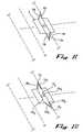
- FIG. 1Cis a schematic representation showing the orientation of buckled struts having equal strut portion lengths.
- FIG. 1Dis a schematic representation showing the orientation of buckled struts wherein some of the buckled struts have unequal strut portion lengths.
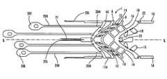
- FIG. 1Bshows a flat pattern of another anastomosis device 1 ′ according to the present invention.
- device 1 ′may be formed in various sizes to suit the dimensions of a graft or vessel to be joined to another site, and devices 1 ′ are formed to have outside diameters as described with regard to device 1 .
- device 1 ′ device 1substantially takes on the shape of an oblique cylinder when fully constructed, similar to the showing of device 1 in FIG. 2 .
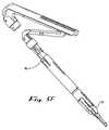
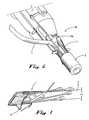
- FIG. 5Ashows a perspective view of another example of a deployment instrument 50 , which is configured to receive and deliver an anastomosis device in performance of an angled end-to-side anastomosis according to the present invention.
- instrument 50includes a main body 52 , which is configured to be hand held by the operator.
- a distal tip portion 60 of instrument 50is configured for receiving, holding and deploying an anastomosis device 1 , 1 ′ according to the present invention.
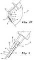
- the end of distal tip portionmay be substantially perpendicular to the longitudinal axis of instrument 50 , as shown in FIG. 5A , or may be angled or beveled with respect to the longitudinal axis, as shown in FIG. 5B .
- Tube 81is linked to tension actuator handle 85 via linkage 87 , actuation link 88 . and clutch member 89 , see FIG. 5D .
- Clutch member 89is interlinked, such as by cross pins 92 for example, between actuation link 88 and a proximal end of a shaft 90 which integrally extends from tube 81 .
- Actuation link 88provides a secondary connection to shaft 90 via a slot 93 through which shaft 90 extends but cannot escape from the distal end of actuation link 88 .
- stop member 70not only helps to correctly position device 1 , 1 ′ in a longitudinal position along the distal portion 60 , but also performs a centering function to keep device 1 , 1 ′ properly centered on the distal portion 60 of deployment device 50 .
- locking member 83is slid proximally (toward handle 85 ) with respect to tension actuators, causing a further biasing of biasing member 95 and exposing the tension actuators 55 for loading the breakaway tines/engagement portions 20 E thereon.
- proximal anastomosistypically requires the proximal anastomosis to be performed before the distal anastomosis is performed. This is disadvantageous for at least two reasons. One reason is that surgeons are currently trained to perform the distal anastomosis prior to performing the proximal anastomosis. A second reason is that, depending upon the location of the coronary artery which is being bypassed, it is very frequently necessary to move the heart out of its natural position, such as by elevating it out of the chest cavity to provide access to the site where the anastomosis is to be performed.
- the engagement portions 20 E of the breakaway tines 20 B which are connected to the non-extending portion of ring 6 Aare provided with elongated openings or slots 20 ES relative to the openings or holes 20 EH in the engagement portions 20 E of the breakaway tines 20 B that connect to the extended, weakened portions of ring 6 A.
- the angulation of device 1 , 1 ′is matched to the desired angulation of the junction of the graft 3 to the host 164 after performance of the anastomosis.
- the angulationwill range from about 30 degrees to about 45 degrees.
- the angulationcan be made greater than 45 degrees, but the benefits of performing an angulated anastomosis begin to significantly decrease with angles greater than about 45 degrees.
- the ring portion 6 Ais drawn against ring 6 by collapsing struts 12 A when deploying a device 1 having a ring portion 6 A which is desired to reduce the angle of the distal end of device 1 only temporarily (see FIG. 13E ).
- tension through breakaway tines 20 Bcauses the buckling section between rings 6 and 8 to collapse or buckle, as shown in FIG. 13B . Due to the partially bent configuration of the struts 12 , a controlled direction of buckling is assured which causes a mushroom-shaped configuration to result as shown.
Landscapes
- Health & Medical Sciences (AREA)
- Life Sciences & Earth Sciences (AREA)
- Surgery (AREA)
- Heart & Thoracic Surgery (AREA)
- Engineering & Computer Science (AREA)
- Biomedical Technology (AREA)
- Nuclear Medicine, Radiotherapy & Molecular Imaging (AREA)
- Medical Informatics (AREA)
- Molecular Biology (AREA)
- Animal Behavior & Ethology (AREA)
- General Health & Medical Sciences (AREA)
- Public Health (AREA)
- Veterinary Medicine (AREA)
- Surgical Instruments (AREA)
Abstract
Description
Claims (57)
Priority Applications (1)
| Application Number | Priority Date | Filing Date | Title |
|---|---|---|---|
| US10/872,071US8162963B2 (en) | 2004-06-17 | 2004-06-17 | Angled anastomosis device, tools and method of using |
Applications Claiming Priority (1)
| Application Number | Priority Date | Filing Date | Title |
|---|---|---|---|
| US10/872,071US8162963B2 (en) | 2004-06-17 | 2004-06-17 | Angled anastomosis device, tools and method of using |
Publications (2)
| Publication Number | Publication Date |
|---|---|
| US20050283173A1 US20050283173A1 (en) | 2005-12-22 |
| US8162963B2true US8162963B2 (en) | 2012-04-24 |
Family
ID=35481633
Family Applications (1)
| Application Number | Title | Priority Date | Filing Date |
|---|---|---|---|
| US10/872,071Active2026-09-16US8162963B2 (en) | 2004-06-17 | 2004-06-17 | Angled anastomosis device, tools and method of using |
Country Status (1)
| Country | Link |
|---|---|
| US (1) | US8162963B2 (en) |
Cited By (4)
| Publication number | Priority date | Publication date | Assignee | Title |
|---|---|---|---|---|
| US20120123454A1 (en)* | 2010-11-11 | 2012-05-17 | Wilson T. Asfora | Sutureless vascular anastomosis connection |
| US10159485B2 (en) | 2010-11-11 | 2018-12-25 | Asfora Ip, Llc | Deployment tool for sutureless vascular anastomosis connection |
| US11751876B2 (en) | 2019-05-07 | 2023-09-12 | Easyflomicro Inc. | Apparatuses for anastomosis of tubular vessels and related methods |
| US11918223B2 (en) | 2018-02-02 | 2024-03-05 | University Of Louisville Research Foundation, Inc. | Sutureless graft anastomotic quick connect system |
Families Citing this family (5)
| Publication number | Priority date | Publication date | Assignee | Title |
|---|---|---|---|---|
| US8388349B2 (en)* | 2009-01-14 | 2013-03-05 | Ams Research Corporation | Anastomosis deployment force training tool |
| DE102009009925B4 (en)* | 2009-02-20 | 2018-09-13 | Fraunhofer-Gesellschaft zur Förderung der angewandten Forschung e.V. | Apparatus for performing an anastomosis |
| DE102010035470B4 (en) | 2010-08-26 | 2015-08-13 | Fraunhofer-Gesellschaft zur Förderung der angewandten Forschung e.V. | Device for performing a side-to-side anastomosis |
| EP2720626B1 (en)* | 2011-06-15 | 2017-06-14 | Phraxis Inc. | Anastomotic connector and system for delivery |
| EP2861182B1 (en) | 2012-06-15 | 2019-02-20 | Phraxis Inc. | Arterial and venous anchor devices forming an anastomotic connector |
Citations (218)
| Publication number | Priority date | Publication date | Assignee | Title |
|---|---|---|---|---|
| US3254651A (en) | 1962-09-12 | 1966-06-07 | Babies Hospital | Surgical anastomosis methods and devices |
| US3254650A (en) | 1962-03-19 | 1966-06-07 | Michael B Collito | Surgical anastomosis methods and devices |
| US3519187A (en) | 1966-12-06 | 1970-07-07 | Nickolai Nickolajevich Kapitan | Instrument for suturing vessels |
| US3774615A (en) | 1971-02-08 | 1973-11-27 | Ceskoslovenska Akademie Ved | Device for connecting or joining the ends of interrupted tubular organs in surgical operations without stitching |
| US4118806A (en) | 1976-02-04 | 1978-10-10 | Thermo Electron Corporation | Prosthetic blood vessel |
| US4214587A (en) | 1979-02-12 | 1980-07-29 | Sakura Chester Y Jr | Anastomosis device and method |
| US4217664A (en) | 1979-02-02 | 1980-08-19 | Faso Joseph M | Prosthesis and method for creating a stoma |
| US4350160A (en) | 1979-11-14 | 1982-09-21 | Kolesov Evgeny V | Instrument for establishing vascular anastomoses |
| US4352358A (en) | 1979-12-28 | 1982-10-05 | Angelchik Jean P | Apparatus for effecting anastomotic procedures |
| US4366819A (en) | 1980-11-17 | 1983-01-04 | Kaster Robert L | Anastomotic fitting |
| US4368736A (en) | 1980-11-17 | 1983-01-18 | Kaster Robert L | Anastomotic fitting |
| US4503568A (en) | 1981-11-25 | 1985-03-12 | New England Deaconess Hospital | Small diameter vascular bypass and method |
| US4523592A (en) | 1983-04-25 | 1985-06-18 | Rollin K. Daniel P.S.C. | Anastomotic coupling means capable of end-to-end and end-to-side anastomosis |
| US4553542A (en) | 1982-02-18 | 1985-11-19 | Schenck Robert R | Methods and apparatus for joining anatomical structures |
| US4589416A (en) | 1983-10-04 | 1986-05-20 | United States Surgical Corporation | Surgical fastener retainer member assembly |
| US4593693A (en) | 1985-04-26 | 1986-06-10 | Schenck Robert R | Methods and apparatus for anastomosing living vessels |
| US4607637A (en) | 1983-07-22 | 1986-08-26 | Anders Berggren | Surgical instrument for performing anastomosis with the aid of ring-like fastening elements and the fastening elements for performing anastomosis |
| US4624257A (en) | 1982-06-24 | 1986-11-25 | Anders Berggren | Surgical instrument for performing anastomosis |
| US4624255A (en) | 1982-02-18 | 1986-11-25 | Schenck Robert R | Apparatus for anastomosing living vessels |
| US4657019A (en) | 1984-04-10 | 1987-04-14 | Idea Research Investment Fund, Inc. | Anastomosis devices and kits |
| US4665906A (en) | 1983-10-14 | 1987-05-19 | Raychem Corporation | Medical devices incorporating sim alloy elements |
| US4721109A (en) | 1986-04-08 | 1988-01-26 | Healey Maureen A | Temporary anastomotic device |
| US4747407A (en) | 1985-09-03 | 1988-05-31 | The Field Surgery Research Department of the Third Military Medical University | Blood vessel anastomat |
| US4752024A (en) | 1986-10-17 | 1988-06-21 | Green David T | Surgical fastener and surgical stapling apparatus |
| US4861330A (en) | 1987-03-12 | 1989-08-29 | Gene Voss | Cardiac assist device and method |
| US4883453A (en) | 1986-10-27 | 1989-11-28 | Ethicoh Inc. | Method of manufacturing synthetic vascular grafts |
| US4892098A (en) | 1985-06-26 | 1990-01-09 | Sauer Jude S | Tubular tissue welding device without moving parts |
| US4907591A (en) | 1988-03-29 | 1990-03-13 | Pfizer Hospital Products Group, Inc. | Surgical instrument for establishing compression anastomosis |
| US4917091A (en) | 1982-06-24 | 1990-04-17 | Unilink Ab | Annular fastening means |
| US4917087A (en) | 1984-04-10 | 1990-04-17 | Walsh Manufacturing (Mississuaga) Limited | Anastomosis devices, kits and method |
| US4930674A (en) | 1989-02-24 | 1990-06-05 | Abiomed, Inc. | Surgical stapler |
| US4997439A (en) | 1989-01-26 | 1991-03-05 | Chen Fusen H | Surgical closure or anastomotic device |
| US5005749A (en) | 1988-07-01 | 1991-04-09 | United States Surgical Corp. | Anastomosis surgical stapling instrument |
| US5015238A (en) | 1989-06-21 | 1991-05-14 | Becton, Dickinson And Company | Expandable obturator and catheter assembly including same |
| US5062842A (en) | 1989-12-21 | 1991-11-05 | Coherent, Inc. | Isotopic co2 laser and method of use for medical treatment |
| US5089006A (en) | 1989-11-29 | 1992-02-18 | Stiles Frank B | Biological duct liner and installation catheter |
| US5104025A (en) | 1990-09-28 | 1992-04-14 | Ethicon, Inc. | Intraluminal anastomotic surgical stapler with detached anvil |
| US5119983A (en) | 1987-05-26 | 1992-06-09 | United States Surgical Corporation | Surgical stapler apparatus |
| US5129913A (en) | 1990-10-04 | 1992-07-14 | Norbert Ruppert | Surgical punch apparatus |
| US5156613A (en) | 1991-02-13 | 1992-10-20 | Interface Biomedical Laboratories Corp. | Collagen welding rod material for use in tissue welding |
| US5156619A (en) | 1990-06-15 | 1992-10-20 | Ehrenfeld William K | Flanged end-to-side vascular graft |
| US5171262A (en) | 1989-06-15 | 1992-12-15 | Cordis Corporation | Non-woven endoprosthesis |
| US5178634A (en) | 1989-03-31 | 1993-01-12 | Wilson Ramos Martinez | Aortic valved tubes for human implants |
| US5192289A (en) | 1989-03-09 | 1993-03-09 | Avatar Design And Development, Inc. | Anastomosis stent and stent selection system |
| US5193731A (en) | 1988-07-01 | 1993-03-16 | United States Surgical Corporation | Anastomosis surgical stapling instrument |
| US5205459A (en) | 1991-08-23 | 1993-04-27 | Ethicon, Inc. | Surgical anastomosis stapling instrument |
| EP0539237A1 (en) | 1991-10-25 | 1993-04-28 | Cook Incorporated | Expandable transluminal graft prosthesis for repair of aneurysm and method for implanting |
| US5211683A (en) | 1991-07-03 | 1993-05-18 | Maginot Thomas J | Method of implanting a graft prosthesis in the body of a patient |
| US5217474A (en) | 1991-07-15 | 1993-06-08 | Zacca Nadim M | Expandable tip atherectomy method and apparatus |
| US5221281A (en) | 1992-06-30 | 1993-06-22 | Valleylab Inc. | Electrosurgical tubular trocar |
| US5222963A (en) | 1991-01-17 | 1993-06-29 | Ethicon, Inc. | Pull-through circular anastomosic intraluminal stapler with absorbable fastener means |
| US5234447A (en) | 1990-08-28 | 1993-08-10 | Robert L. Kaster | Side-to-end vascular anastomotic staple apparatus |
| US5250060A (en) | 1992-06-26 | 1993-10-05 | Carbo Paul L | Angioplasty apparatus |
| US5250058A (en) | 1991-01-17 | 1993-10-05 | Ethicon, Inc. | Absorbable anastomosic fastener means |
| US5290298A (en) | 1990-05-07 | 1994-03-01 | United States Surgical Corporation | Fragmentable anastomotic device |
| US5304220A (en) | 1991-07-03 | 1994-04-19 | Maginot Thomas J | Method and apparatus for implanting a graft prosthesis in the body of a patient |
| US5314435A (en) | 1992-05-19 | 1994-05-24 | United States Surgical Corporation | Anvil delivery system |
| US5333773A (en) | 1991-08-23 | 1994-08-02 | Ethicon, Inc. | Sealing means for endoscopic surgical anastomosis stapling instrument |
| US5336233A (en) | 1989-01-26 | 1994-08-09 | Chen Fusen H | Anastomotic device |
| US5350104A (en) | 1991-08-23 | 1994-09-27 | Ethicon, Inc. | Sealing means for endoscopic surgical anastomosis stapling instrument |
| US5354302A (en) | 1992-11-06 | 1994-10-11 | Ko Sung Tao | Medical device and method for facilitating intra-tissue visual observation and manipulation of distensible tissues |
| US5364389A (en) | 1992-11-25 | 1994-11-15 | Premier Laser Systems, Inc. | Method and apparatus for sealing and/or grasping luminal tissue |
| US5366462A (en) | 1990-08-28 | 1994-11-22 | Robert L. Kaster | Method of side-to-end vascular anastomotic stapling |
| US5392979A (en) | 1987-05-26 | 1995-02-28 | United States Surgical Corporation | Surgical stapler apparatus |
| US5395311A (en) | 1990-05-14 | 1995-03-07 | Andrews; Winston A. | Atherectomy catheter |
| US5395030A (en) | 1992-06-04 | 1995-03-07 | Olympus Optical Co., Ltd. | Surgical device for stapling and fastening body tissues |
| US5443497A (en) | 1993-11-22 | 1995-08-22 | The Johns Hopkins University | Percutaneous prosthetic by-pass graft and method of use |
| EP0517252B1 (en) | 1991-06-06 | 1995-08-30 | Blake, Joseph Walter III | Disposable vascular punch |
| US5447514A (en) | 1993-10-01 | 1995-09-05 | United States Surgical Corporation | Circular anastomosis device |
| US5454825A (en) | 1993-10-01 | 1995-10-03 | United States Surgical Corporation | Circular anastomosis device with seal |
| US5456714A (en) | 1991-07-04 | 1995-10-10 | Owen; Earl R. | Tubular surgical implant having a locking ring and flange |
| US5464449A (en) | 1993-07-08 | 1995-11-07 | Thomas J. Fogarty | Internal graft prosthesis and delivery system |
| US5465895A (en) | 1994-02-03 | 1995-11-14 | Ethicon Endo-Surgery, Inc. | Surgical stapler instrument |
| US5478354A (en) | 1993-07-14 | 1995-12-26 | United States Surgical Corporation | Wound closing apparatus and method |
| EP0701800A1 (en) | 1994-09-15 | 1996-03-20 | C.R. Bard, Inc. | Method and apparatus for recapture of hooked endoprosthesis |
| US5503635A (en) | 1993-11-12 | 1996-04-02 | United States Surgical Corporation | Apparatus and method for performing compressional anastomoses |
| US5515478A (en) | 1992-08-10 | 1996-05-07 | Computer Motion, Inc. | Automated endoscope system for optimal positioning |
| US5522834A (en) | 1992-10-15 | 1996-06-04 | Applied Medical Resources Corporation | Internal mammary artery catheter and method |
| US5524180A (en) | 1992-08-10 | 1996-06-04 | Computer Motion, Inc. | Automated endoscope system for optimal positioning |
| US5534761A (en) | 1991-05-21 | 1996-07-09 | Crippa; Ugo | Mechanism for movements of prefixed path, referable as of elliptical shape |
| US5540677A (en) | 1990-06-15 | 1996-07-30 | Rare Earth Medical, Inc. | Endoscopic systems for photoreactive suturing of biological materials |
| US5553198A (en) | 1993-12-15 | 1996-09-03 | Computer Motion, Inc. | Automated endoscope system for optimal positioning |
| US5556405A (en) | 1995-10-13 | 1996-09-17 | Interventional Technologies Inc. | Universal dilator with reciprocal incisor |
| US5558667A (en) | 1994-12-14 | 1996-09-24 | Coherent, Inc. | Method and apparatus for treating vascular lesions |
| US5643340A (en) | 1994-10-27 | 1997-07-01 | Nunokawa; Mioko | Synthetic vascular prosthesis |
| US5645520A (en) | 1994-10-12 | 1997-07-08 | Computer Motion, Inc. | Shape memory alloy actuated rod for endoscopic instruments |
| US5657429A (en) | 1992-08-10 | 1997-08-12 | Computer Motion, Inc. | Automated endoscope system optimal positioning |
| US5669934A (en) | 1991-02-13 | 1997-09-23 | Fusion Medical Technologies, Inc. | Methods for joining tissue by applying radiofrequency energy to performed collagen films and sheets |
| US5669918A (en) | 1995-03-16 | 1997-09-23 | Deutsche Forschungsanstalt Fur Luft-Und Raumfahrt E.V. | Surgical instrument for preparing an anastomosis in minimally invasive surgery |
| US5676670A (en) | 1996-06-14 | 1997-10-14 | Beth Israel Deaconess Medical Center | Catheter apparatus and method for creating a vascular bypass in-vivo |
| DE29713335U1 (en) | 1997-07-26 | 1997-10-16 | Quatchadze, Georg, Dr.med., 56249 Herschbach | Surgical instrument for connecting two hollow organs |
| US5693088A (en) | 1993-11-08 | 1997-12-02 | Lazarus; Harrison M. | Intraluminal vascular graft |
| US5695504A (en) | 1995-02-24 | 1997-12-09 | Heartport, Inc. | Devices and methods for performing a vascular anastomosis |
| US5702412A (en) | 1995-10-03 | 1997-12-30 | Cedars-Sinai Medical Center | Method and devices for performing vascular anastomosis |
| US5707380A (en) | 1996-07-23 | 1998-01-13 | United States Surgical Corporation | Anastomosis instrument and method |
| US5707362A (en) | 1992-04-15 | 1998-01-13 | Yoon; Inbae | Penetrating instrument having an expandable anchoring portion for triggering protrusion of a safety member and/or retraction of a penetrating member |
| US5709693A (en) | 1996-02-20 | 1998-01-20 | Cardiothoracic System, Inc. | Stitcher |
| US5709335A (en) | 1994-06-17 | 1998-01-20 | Heartport, Inc. | Surgical stapling instrument and method thereof |
| US5725533A (en) | 1990-03-09 | 1998-03-10 | Nobel Biocare Ab | Torsional tightener for bone anchoring or implant elements/tools |
| US5725544A (en) | 1993-12-23 | 1998-03-10 | Oticon A/S | Method and instrument for establishing the receiving site of a coronary artery bypass graft |
| US5725553A (en) | 1996-02-29 | 1998-03-10 | Moenning; Stephen P. | Apparatus and method for protecting a port site opening in the wall of a body cavity |
| US5732872A (en) | 1994-06-17 | 1998-03-31 | Heartport, Inc. | Surgical stapling instrument |
| US5754741A (en) | 1992-08-10 | 1998-05-19 | Computer Motion, Inc. | Automated endoscope for optimal positioning |
| US5762458A (en) | 1996-02-20 | 1998-06-09 | Computer Motion, Inc. | Method and apparatus for performing minimally invasive cardiac procedures |
| US5779718A (en) | 1992-10-09 | 1998-07-14 | United States Surgical Corporation | Method of anastomosing a vessel using a surgical clip applier |
| US5789371A (en) | 1997-04-22 | 1998-08-04 | Rhodia Inc. | Amphoteric surfactants having multiple hydrophobic and hydrophilic groups |
| US5792135A (en) | 1996-05-20 | 1998-08-11 | Intuitive Surgical, Inc. | Articulated surgical instrument for performing minimally invasive surgery with enhanced dexterity and sensitivity |
| US5797920A (en) | 1996-06-14 | 1998-08-25 | Beth Israel Deaconess Medical Center | Catheter apparatus and method using a shape-memory alloy cuff for creating a bypass graft in-vivo |
| US5797900A (en) | 1996-05-20 | 1998-08-25 | Intuitive Surgical, Inc. | Wrist mechanism for surgical instrument for performing minimally invasive surgery with enhanced dexterity and sensitivity |
| US5799661A (en) | 1993-02-22 | 1998-09-01 | Heartport, Inc. | Devices and methods for port-access multivessel coronary artery bypass surgery |
| US5799857A (en) | 1993-10-07 | 1998-09-01 | United States Surgical Corporation | Circular anastomosis device |
| US5807377A (en) | 1996-05-20 | 1998-09-15 | Intuitive Surgical, Inc. | Force-reflecting surgical instrument and positioning mechanism for performing minimally invasive surgery with enhanced dexterity and sensitivity |
| US5814073A (en) | 1996-12-13 | 1998-09-29 | Bonutti; Peter M. | Method and apparatus for positioning a suture anchor |
| US5827316A (en) | 1997-06-05 | 1998-10-27 | Atrion Medical Products, Inc. | Rotating aortic punch |
| US5833698A (en)* | 1996-07-23 | 1998-11-10 | United States Surgical Corporation | Anastomosis instrument and method |
| US5855583A (en) | 1996-02-20 | 1999-01-05 | Computer Motion, Inc. | Method and apparatus for performing minimally invasive cardiac procedures |
| US5868763A (en) | 1996-09-16 | 1999-02-09 | Guidant Corporation | Means and methods for performing an anastomosis |
| US5875782A (en) | 1996-11-14 | 1999-03-02 | Cardiothoracic Systems, Inc. | Methods and devices for minimally invasive coronary artery revascularization on a beating heart without cardiopulmonary bypass |
| US5879371A (en) | 1997-01-09 | 1999-03-09 | Elective Vascular Interventions, Inc. | Ferruled loop surgical fasteners, instruments, and methods for minimally invasive vascular and endoscopic surgery |
| US5881943A (en) | 1994-06-17 | 1999-03-16 | Heartport, Inc. | Surgical anastomosis apparatus and method thereof |
| US5893369A (en) | 1997-02-24 | 1999-04-13 | Lemole; Gerald M. | Procedure for bypassing an occlusion in a blood vessel |
| EP0913125A2 (en) | 1992-02-03 | 1999-05-06 | Ethicon Endo-Surgery, Inc. | Ultrasonics scalpel blade and methods of application |
| US5904697A (en) | 1995-02-24 | 1999-05-18 | Heartport, Inc. | Devices and methods for performing a vascular anastomosis |
| US5911036A (en) | 1995-09-15 | 1999-06-08 | Computer Motion, Inc. | Head cursor control interface for an automated endoscope system for optimal positioning |
| US5915616A (en) | 1991-10-18 | 1999-06-29 | United States Surgical Corporation | Surgical fastener applying apparatus |
| US5921995A (en) | 1996-10-16 | 1999-07-13 | Nitinol Medical Technologies, Inc. | Anastomosis Device |
| US5944730A (en) | 1997-05-19 | 1999-08-31 | Cardio Medical Solutions, Inc. | Device and method for assisting end-to-side anastomosis |
| EP0938870A1 (en) | 1998-02-26 | 1999-09-01 | Ethicon Endo-Surgery, Inc. | Surgical anastomosis instrument |
| US5968089A (en) | 1996-08-21 | 1999-10-19 | Krajicek; Milan | Internal shield of an anastomosis in a vascular system |
| US5976159A (en) | 1995-02-24 | 1999-11-02 | Heartport, Inc. | Surgical clips and methods for tissue approximation |
| US5989276A (en) | 1996-11-08 | 1999-11-23 | Advanced Bypass Technologies, Inc. | Percutaneous bypass graft and securing system |
| US6001124A (en) | 1997-10-09 | 1999-12-14 | Vascular Science, Inc. | Oblique-angle graft connectors |
| US6007544A (en) | 1996-06-14 | 1999-12-28 | Beth Israel Deaconess Medical Center | Catheter apparatus having an improved shape-memory alloy cuff and inflatable on-demand balloon for creating a bypass graft in-vivo |
| US6013190A (en) | 1998-01-21 | 2000-01-11 | Vascular Science Inc. | Catheters with integrated lumen and methods of their manufacture and use |
| US6022367A (en) | 1997-06-18 | 2000-02-08 | United States Surgical | Surgical apparatus for forming a hole in a blood vessel |
| US6024748A (en) | 1996-07-23 | 2000-02-15 | United States Surgical Corporation | Singleshot anastomosis instrument with detachable loading unit and method |
| US6030370A (en) | 1997-02-05 | 2000-02-29 | Aesculap Ag And Co. Kg | Surgical instrument |
| US6030392A (en) | 1995-01-18 | 2000-02-29 | Motorola, Inc. | Connector for hollow anatomical structures and methods of use |
| US6030395A (en) | 1997-05-22 | 2000-02-29 | Kensey Nash Corporation | Anastomosis connection system |
| US6036704A (en) | 1999-05-13 | 2000-03-14 | Yoon; Inbae | Anastomosis apparatus and method for anastomosing an anatomical tubular structure |
| US6036702A (en) | 1997-04-23 | 2000-03-14 | Vascular Science Inc. | Medical grafting connectors and fasteners |
| US6036700A (en) | 1998-07-14 | 2000-03-14 | Ethicon Endo-Surgery, Inc. | Surgical anastomosis instrument |
| US6036699A (en) | 1992-12-10 | 2000-03-14 | Perclose, Inc. | Device and method for suturing tissue |
| US6036703A (en) | 1998-02-06 | 2000-03-14 | Ethicon Endo-Surgery Inc. | Method and apparatus for establishing anastomotic passageways |
| EP0990420A2 (en) | 1998-09-28 | 2000-04-05 | United States Surgical Corporation | Anastomosis instrument |
| US6050472A (en) | 1996-04-26 | 2000-04-18 | Olympus Optical Co., Ltd. | Surgical anastomosis stapler |
| US6053390A (en) | 1992-05-19 | 2000-04-25 | United States Surgical | Anvil for surgical stapler |
| US6066144A (en) | 1997-10-07 | 2000-05-23 | Ethicon Endo-Surgery, Inc. | Surgical anastomosis method |
| US6066148A (en) | 1996-04-30 | 2000-05-23 | Oticon A/S | Method and anastomotic instrument for use when performing an end-to-side anastomosis |
| US6068637A (en) | 1995-10-03 | 2000-05-30 | Cedar Sinai Medical Center | Method and devices for performing vascular anastomosis |
| US6074416A (en) | 1997-10-09 | 2000-06-13 | St. Jude Medical Cardiovascular Group, Inc. | Wire connector structures for tubular grafts |
| US6074401A (en) | 1997-01-09 | 2000-06-13 | Coalescent Surgical, Inc. | Pinned retainer surgical fasteners, instruments and methods for minimally invasive vascular and endoscopic surgery |
| US6080173A (en) | 1999-05-26 | 2000-06-27 | Idx Medical Ltd. | Tissue punching instrument |
| US6110187A (en) | 1995-02-24 | 2000-08-29 | Heartport, Inc. | Device and method for minimizing heart displacements during a beating heart surgical procedure |
| US6110188A (en) | 1998-03-09 | 2000-08-29 | Corvascular, Inc. | Anastomosis method |
| US6113612A (en) | 1998-11-06 | 2000-09-05 | St. Jude Medical Cardiovascular Group, Inc. | Medical anastomosis apparatus |
| US6117148A (en) | 1997-10-17 | 2000-09-12 | Ravo; Biagio | Intraluminal anastomotic device |
| US6146393A (en) | 1998-12-18 | 2000-11-14 | Wakabayashi; Akio | External tubular stapling device for anastomosing a vascular graft to an anastomosing sheath |
| US6149681A (en) | 1996-09-20 | 2000-11-21 | Converge Medical, Inc. | Radially expanding prostheses and systems for their deployment |
| US6149658A (en) | 1997-01-09 | 2000-11-21 | Coalescent Surgical, Inc. | Sutured staple surgical fasteners, instruments and methods for minimally invasive vascular and endoscopic surgery |
| US6152945A (en) | 1997-04-23 | 2000-11-28 | St. Jude Medical Cardiovascular Group, Inc. | Tubular medical graft connectors |
| US6152937A (en)* | 1998-11-06 | 2000-11-28 | St. Jude Medical Cardiovascular Group, Inc. | Medical graft connector and methods of making and installing same |
| US6165185A (en) | 1999-07-28 | 2000-12-26 | Vasconnect, Inc. | Method for interconnecting vessels in a patient |
| US6167889B1 (en) | 1995-04-10 | 2001-01-02 | Cardiothoracic Systems, Inc. | Method for coronary artery bypass |
| US6168623B1 (en) | 1998-08-31 | 2001-01-02 | Cardiothoracic Systems, Inc. | Deformable conduits and methods for shunting bodily fluid during surgery |
| US6176864B1 (en) | 1998-03-09 | 2001-01-23 | Corvascular, Inc. | Anastomosis device and method |
| US6179849B1 (en) | 1999-06-10 | 2001-01-30 | Vascular Innovations, Inc. | Sutureless closure for connecting a bypass graft to a target vessel |
| US6186942B1 (en) | 1997-04-23 | 2001-02-13 | St. Jude Medical Cardiovascular Group, Inc. | Medical grafting methods and apparatus |
| US6187020B1 (en) | 1998-04-17 | 2001-02-13 | Laboratoire Perouse Implant | Connecting device for anastomosis, device for fitting fasteners and implant including them |
| US6190396B1 (en) | 1999-09-14 | 2001-02-20 | Perclose, Inc. | Device and method for deploying and organizing sutures for anastomotic and other attachments |
| US6190590B1 (en) | 1996-02-28 | 2001-02-20 | Impra, Inc. | Apparatus and method for making flanged graft for end-to-side anastomosis |
| US6193734B1 (en) | 1998-01-23 | 2001-02-27 | Heartport, Inc. | System for performing vascular anastomoses |
| US6193129B1 (en) | 2000-01-24 | 2001-02-27 | Ethicon Endo-Surgery, Inc. | Cutting blade for a surgical anastomosis stapling instrument |
| US6206912B1 (en) | 1996-11-07 | 2001-03-27 | St. Jude Medical Anastomotic Technology Group Inc. | Medical grafting methods and apparatus |
| US6217585B1 (en) | 1996-08-16 | 2001-04-17 | Converge Medical, Inc. | Mechanical stent and graft delivery system |
| US6235054B1 (en) | 1998-02-27 | 2001-05-22 | St. Jude Medical Cardiovascular Group, Inc. | Grafts with suture connectors |
| US6241741B1 (en) | 1998-03-09 | 2001-06-05 | Corvascular Surgical Systems, Inc. | Anastomosis device and method |
| US6293955B1 (en) | 1996-09-20 | 2001-09-25 | Converge Medical, Inc. | Percutaneous bypass graft and securing system |
| US20020013591A1 (en) | 1998-06-10 | 2002-01-31 | Fleischman Sidney D. | Anastomosis systems |
| US6391038B2 (en) | 1999-07-28 | 2002-05-21 | Cardica, Inc. | Anastomosis system and method for controlling a tissue site |
| US6402764B1 (en) | 1999-11-15 | 2002-06-11 | Cardica, Inc. | Everter and threadthrough system for attaching graft vessel to anastomosis device |
| US6419681B1 (en) | 1999-05-18 | 2002-07-16 | Cardica, Inc. | Implantable medical device such as an anastomosis device |
| US6458140B2 (en) | 1999-07-28 | 2002-10-01 | Vasconnect, Inc. | Devices and methods for interconnecting vessels |
| US6461320B1 (en) | 1998-08-12 | 2002-10-08 | Cardica, Inc. | Method and system for attaching a graft to a blood vessel |
| US6471713B1 (en) | 2000-11-13 | 2002-10-29 | Cardica, Inc. | System for deploying an anastomosis device and method of performing anastomosis |
| US20020173809A1 (en) | 1999-09-01 | 2002-11-21 | Fleischman Sidney D. | Sutureless anastomosis system deployment concepts |
| US20020183769A1 (en)* | 2001-05-30 | 2002-12-05 | St. Jude Medical Atg, Inc. | Medical grafting methods and apparatus |
| US6494889B1 (en) | 1999-09-01 | 2002-12-17 | Converge Medical, Inc. | Additional sutureless anastomosis embodiments |
| US6497710B2 (en) | 1998-08-12 | 2002-12-24 | Cardica, Inc. | Method and system for attaching a graft to a blood vessel |
| US6508252B1 (en) | 1998-11-06 | 2003-01-21 | St. Jude Medical Atg, Inc. | Medical grafting methods and apparatus |
| US6511491B2 (en) | 1999-03-09 | 2003-01-28 | St. Jude Medical Atg, Inc. | Medical grafting methods and apparatus |
| US20030023253A1 (en) | 2001-04-27 | 2003-01-30 | Cardica, Inc. | Anastomosis system |
| US6514265B2 (en) | 1999-03-01 | 2003-02-04 | Coalescent Surgical, Inc. | Tissue connector apparatus with cable release |
| US6517558B2 (en) | 1999-01-15 | 2003-02-11 | Ventrica, Inc. | Methods and devices for forming vascular anastomoses |
| US6530932B1 (en) | 2000-08-30 | 2003-03-11 | Ethicon Endo-Surgery, Inc. | Anastomosis device having improved tissue presentation |
| US6537288B2 (en) | 1999-05-18 | 2003-03-25 | Cardica, Inc. | Implantable medical device such as an anastomosis device |
| US20030074012A1 (en) | 2000-10-10 | 2003-04-17 | Coalescent Surgical, Inc. | Minimally invasive annuloplasty procedure and apparatus |
| US6551332B1 (en) | 2000-03-31 | 2003-04-22 | Coalescent Surgical, Inc. | Multiple bias surgical fastener |
| US20030078603A1 (en) | 1999-03-01 | 2003-04-24 | Coalescent Surgical, Inc. | Tissue connector apparatus and methods |
| US6554764B1 (en) | 2000-11-13 | 2003-04-29 | Cardica, Inc. | Graft vessel preparation device and methods for using the same |
| US6565581B1 (en) | 1996-09-16 | 2003-05-20 | Origin Medsystems, Inc. | Apparatus and method for performing an anastomosis |
| US6573286B1 (en) | 2002-06-21 | 2003-06-03 | Dow Agrosciences Llc | 2-(2,6-disubstituted phenyl)-4-aryl-5-alkyl-1,3-oxazoline compounds |
| US6582463B1 (en) | 2000-10-11 | 2003-06-24 | Heartstent Corporation | Autoanastomosis |
| US6596003B1 (en) | 2000-06-28 | 2003-07-22 | Genzyme Corporation | Vascular anastomosis device |
| US6602263B1 (en)* | 1999-11-30 | 2003-08-05 | St. Jude Medical Atg, Inc. | Medical grafting methods and apparatus |
| US6605113B2 (en) | 1999-08-04 | 2003-08-12 | Percardia Inc. | Vascular graft bypass |
| US6605098B2 (en) | 2001-09-28 | 2003-08-12 | Ethicon, Inc. | Surgical device for creating an anastomosis between first and second hollow organs |
| US6605053B1 (en) | 1999-09-10 | 2003-08-12 | Percardia, Inc. | Conduit designs and related methods for optimal flow control |
| US6607541B1 (en) | 1998-06-03 | 2003-08-19 | Coalescent Surgical, Inc. | Tissue connector apparatus and methods |
| US6613058B1 (en) | 2000-08-30 | 2003-09-02 | Ethicon Endo-Surgery, Inc. | Anastomosis device having needle receiver for capturing the needle |
| US6616675B1 (en) | 1996-02-02 | 2003-09-09 | Transvascular, Inc. | Methods and apparatus for connecting openings formed in adjacent blood vessels or other anatomical structures |
| US6666832B1 (en) | 2002-01-07 | 2003-12-23 | Cardica, Inc. | Surgical measurement tool |
| US6685739B2 (en)* | 1999-10-21 | 2004-02-03 | Scimed Life Systems, Inc. | Implantable prosthetic valve |
| US6695878B2 (en)* | 2000-06-26 | 2004-02-24 | Rex Medical, L.P. | Vascular device for valve leaflet apposition |
| US6719769B2 (en) | 1999-11-15 | 2004-04-13 | Cardica, Inc. | Integrated anastomosis tool with graft vessel attachment device and cutting device |
| US6972023B2 (en)* | 2001-07-05 | 2005-12-06 | Converge Medical, Inc. | Distal anastomosis system |
| US7063711B1 (en)* | 1998-05-29 | 2006-06-20 | By-Pass, Inc. | Vascular surgery |
| US7585306B2 (en)* | 2003-12-24 | 2009-09-08 | Maquet Cardiovascular Llc | Anastomosis device, tools and methods of using |
- 2004
- 2004-06-17USUS10/872,071patent/US8162963B2/enactiveActive
Patent Citations (280)
| Publication number | Priority date | Publication date | Assignee | Title |
|---|---|---|---|---|
| US3254650A (en) | 1962-03-19 | 1966-06-07 | Michael B Collito | Surgical anastomosis methods and devices |
| US3254651A (en) | 1962-09-12 | 1966-06-07 | Babies Hospital | Surgical anastomosis methods and devices |
| US3519187A (en) | 1966-12-06 | 1970-07-07 | Nickolai Nickolajevich Kapitan | Instrument for suturing vessels |
| US3774615A (en) | 1971-02-08 | 1973-11-27 | Ceskoslovenska Akademie Ved | Device for connecting or joining the ends of interrupted tubular organs in surgical operations without stitching |
| US4118806A (en) | 1976-02-04 | 1978-10-10 | Thermo Electron Corporation | Prosthetic blood vessel |
| US4217664A (en) | 1979-02-02 | 1980-08-19 | Faso Joseph M | Prosthesis and method for creating a stoma |
| US4214587A (en) | 1979-02-12 | 1980-07-29 | Sakura Chester Y Jr | Anastomosis device and method |
| US4350160A (en) | 1979-11-14 | 1982-09-21 | Kolesov Evgeny V | Instrument for establishing vascular anastomoses |
| US4352358A (en) | 1979-12-28 | 1982-10-05 | Angelchik Jean P | Apparatus for effecting anastomotic procedures |
| US4366819A (en) | 1980-11-17 | 1983-01-04 | Kaster Robert L | Anastomotic fitting |
| US4368736A (en) | 1980-11-17 | 1983-01-18 | Kaster Robert L | Anastomotic fitting |
| US4503568A (en) | 1981-11-25 | 1985-03-12 | New England Deaconess Hospital | Small diameter vascular bypass and method |
| US4553542A (en) | 1982-02-18 | 1985-11-19 | Schenck Robert R | Methods and apparatus for joining anatomical structures |
| US4624255A (en) | 1982-02-18 | 1986-11-25 | Schenck Robert R | Apparatus for anastomosing living vessels |
| US4917090A (en) | 1982-06-24 | 1990-04-17 | Unilink, Inc. | Method for performing an anastomosis |
| US4624257A (en) | 1982-06-24 | 1986-11-25 | Anders Berggren | Surgical instrument for performing anastomosis |
| US4917091A (en) | 1982-06-24 | 1990-04-17 | Unilink Ab | Annular fastening means |
| US4523592A (en) | 1983-04-25 | 1985-06-18 | Rollin K. Daniel P.S.C. | Anastomotic coupling means capable of end-to-end and end-to-side anastomosis |
| US4607637A (en) | 1983-07-22 | 1986-08-26 | Anders Berggren | Surgical instrument for performing anastomosis with the aid of ring-like fastening elements and the fastening elements for performing anastomosis |
| US4589416A (en) | 1983-10-04 | 1986-05-20 | United States Surgical Corporation | Surgical fastener retainer member assembly |
| US4665906A (en) | 1983-10-14 | 1987-05-19 | Raychem Corporation | Medical devices incorporating sim alloy elements |
| US4657019A (en) | 1984-04-10 | 1987-04-14 | Idea Research Investment Fund, Inc. | Anastomosis devices and kits |
| US4917087A (en) | 1984-04-10 | 1990-04-17 | Walsh Manufacturing (Mississuaga) Limited | Anastomosis devices, kits and method |
| US4593693A (en) | 1985-04-26 | 1986-06-10 | Schenck Robert R | Methods and apparatus for anastomosing living vessels |
| US4892098A (en) | 1985-06-26 | 1990-01-09 | Sauer Jude S | Tubular tissue welding device without moving parts |
| US4747407A (en) | 1985-09-03 | 1988-05-31 | The Field Surgery Research Department of the Third Military Medical University | Blood vessel anastomat |
| US4721109A (en) | 1986-04-08 | 1988-01-26 | Healey Maureen A | Temporary anastomotic device |
| US4752024A (en) | 1986-10-17 | 1988-06-21 | Green David T | Surgical fastener and surgical stapling apparatus |
| US4883453A (en) | 1986-10-27 | 1989-11-28 | Ethicoh Inc. | Method of manufacturing synthetic vascular grafts |
| US4861330A (en) | 1987-03-12 | 1989-08-29 | Gene Voss | Cardiac assist device and method |
| US5392979A (en) | 1987-05-26 | 1995-02-28 | United States Surgical Corporation | Surgical stapler apparatus |
| US5119983A (en) | 1987-05-26 | 1992-06-09 | United States Surgical Corporation | Surgical stapler apparatus |
| US4907591A (en) | 1988-03-29 | 1990-03-13 | Pfizer Hospital Products Group, Inc. | Surgical instrument for establishing compression anastomosis |
| US5193731A (en) | 1988-07-01 | 1993-03-16 | United States Surgical Corporation | Anastomosis surgical stapling instrument |
| US5005749A (en) | 1988-07-01 | 1991-04-09 | United States Surgical Corp. | Anastomosis surgical stapling instrument |
| US4997439A (en) | 1989-01-26 | 1991-03-05 | Chen Fusen H | Surgical closure or anastomotic device |
| US5336233A (en) | 1989-01-26 | 1994-08-09 | Chen Fusen H | Anastomotic device |
| US4930674A (en) | 1989-02-24 | 1990-06-05 | Abiomed, Inc. | Surgical stapler |
| US5192289A (en) | 1989-03-09 | 1993-03-09 | Avatar Design And Development, Inc. | Anastomosis stent and stent selection system |
| US5314468A (en) | 1989-03-31 | 1994-05-24 | Wilson Ramos Martinez | Aortic valved tubes for human implants |
| US5178634A (en) | 1989-03-31 | 1993-01-12 | Wilson Ramos Martinez | Aortic valved tubes for human implants |
| US5171262A (en) | 1989-06-15 | 1992-12-15 | Cordis Corporation | Non-woven endoprosthesis |
| US5015238A (en) | 1989-06-21 | 1991-05-14 | Becton, Dickinson And Company | Expandable obturator and catheter assembly including same |
| US5089006A (en) | 1989-11-29 | 1992-02-18 | Stiles Frank B | Biological duct liner and installation catheter |
| US5062842A (en) | 1989-12-21 | 1991-11-05 | Coherent, Inc. | Isotopic co2 laser and method of use for medical treatment |
| US5725533A (en) | 1990-03-09 | 1998-03-10 | Nobel Biocare Ab | Torsional tightener for bone anchoring or implant elements/tools |
| US5290298A (en) | 1990-05-07 | 1994-03-01 | United States Surgical Corporation | Fragmentable anastomotic device |
| US5395311A (en) | 1990-05-14 | 1995-03-07 | Andrews; Winston A. | Atherectomy catheter |
| US5540677A (en) | 1990-06-15 | 1996-07-30 | Rare Earth Medical, Inc. | Endoscopic systems for photoreactive suturing of biological materials |
| US5156619A (en) | 1990-06-15 | 1992-10-20 | Ehrenfeld William K | Flanged end-to-side vascular graft |
| US5234447A (en) | 1990-08-28 | 1993-08-10 | Robert L. Kaster | Side-to-end vascular anastomotic staple apparatus |
| US5366462A (en) | 1990-08-28 | 1994-11-22 | Robert L. Kaster | Method of side-to-end vascular anastomotic stapling |
| US5104025A (en) | 1990-09-28 | 1992-04-14 | Ethicon, Inc. | Intraluminal anastomotic surgical stapler with detached anvil |
| US5129913A (en) | 1990-10-04 | 1992-07-14 | Norbert Ruppert | Surgical punch apparatus |
| US5250058A (en) | 1991-01-17 | 1993-10-05 | Ethicon, Inc. | Absorbable anastomosic fastener means |
| US5222963A (en) | 1991-01-17 | 1993-06-29 | Ethicon, Inc. | Pull-through circular anastomosic intraluminal stapler with absorbable fastener means |
| US5669934A (en) | 1991-02-13 | 1997-09-23 | Fusion Medical Technologies, Inc. | Methods for joining tissue by applying radiofrequency energy to performed collagen films and sheets |
| US5156613A (en) | 1991-02-13 | 1992-10-20 | Interface Biomedical Laboratories Corp. | Collagen welding rod material for use in tissue welding |
| US5534761A (en) | 1991-05-21 | 1996-07-09 | Crippa; Ugo | Mechanism for movements of prefixed path, referable as of elliptical shape |
| EP0517252B1 (en) | 1991-06-06 | 1995-08-30 | Blake, Joseph Walter III | Disposable vascular punch |
| US5456712A (en) | 1991-07-03 | 1995-10-10 | Maginot; Thomas J. | Graft and stent assembly |
| US5304220A (en) | 1991-07-03 | 1994-04-19 | Maginot Thomas J | Method and apparatus for implanting a graft prosthesis in the body of a patient |
| US6599313B1 (en) | 1991-07-03 | 2003-07-29 | Cardiothoracic Systems, Inc. | Extravascular bypass grafting method utilizing an intravascular approach |
| US5571167A (en) | 1991-07-03 | 1996-11-05 | Maginot; Thomas J. | Bypass grafting method |
| US6401721B1 (en) | 1991-07-03 | 2002-06-11 | Cardiothoracic Systems, Inc. | Endoscopic bypass grafting method utilizing an inguinal approach |
| US5211683A (en) | 1991-07-03 | 1993-05-18 | Maginot Thomas J | Method of implanting a graft prosthesis in the body of a patient |
| US5456714A (en) | 1991-07-04 | 1995-10-10 | Owen; Earl R. | Tubular surgical implant having a locking ring and flange |
| US5217474A (en) | 1991-07-15 | 1993-06-08 | Zacca Nadim M | Expandable tip atherectomy method and apparatus |
| US5292053A (en) | 1991-08-23 | 1994-03-08 | Ethicon, Inc. | Surgical anastomosis stapling instrument |
| US5205459A (en) | 1991-08-23 | 1993-04-27 | Ethicon, Inc. | Surgical anastomosis stapling instrument |
| US5285945A (en) | 1991-08-23 | 1994-02-15 | Ethicon, Inc. | Surgical anastomosis stapling instrument |
| US5275322A (en) | 1991-08-23 | 1994-01-04 | Ethicon, Inc. | Surgical anastomosis stapling instrument |
| US5271544A (en) | 1991-08-23 | 1993-12-21 | Ethicon, Inc. | Surgical anastomosis stapling instrument |
| US5350104A (en) | 1991-08-23 | 1994-09-27 | Ethicon, Inc. | Sealing means for endoscopic surgical anastomosis stapling instrument |
| US5533661A (en) | 1991-08-23 | 1996-07-09 | Ethicon, Inc. | Sealing means for endoscopic surgical anastomosis stapling instrument |
| US5333773A (en) | 1991-08-23 | 1994-08-02 | Ethicon, Inc. | Sealing means for endoscopic surgical anastomosis stapling instrument |
| US5915616A (en) | 1991-10-18 | 1999-06-29 | United States Surgical Corporation | Surgical fastener applying apparatus |
| EP0539237A1 (en) | 1991-10-25 | 1993-04-28 | Cook Incorporated | Expandable transluminal graft prosthesis for repair of aneurysm and method for implanting |
| EP0913125A3 (en) | 1992-02-03 | 2000-07-05 | Ethicon Endo-Surgery, Inc. | Ultrasonics scalpel blade and methods of application |
| EP0913125A2 (en) | 1992-02-03 | 1999-05-06 | Ethicon Endo-Surgery, Inc. | Ultrasonics scalpel blade and methods of application |
| US5707362A (en) | 1992-04-15 | 1998-01-13 | Yoon; Inbae | Penetrating instrument having an expandable anchoring portion for triggering protrusion of a safety member and/or retraction of a penetrating member |
| US5314435A (en) | 1992-05-19 | 1994-05-24 | United States Surgical Corporation | Anvil delivery system |
| US6053390A (en) | 1992-05-19 | 2000-04-25 | United States Surgical | Anvil for surgical stapler |
| US5395030A (en) | 1992-06-04 | 1995-03-07 | Olympus Optical Co., Ltd. | Surgical device for stapling and fastening body tissues |
| US5250060A (en) | 1992-06-26 | 1993-10-05 | Carbo Paul L | Angioplasty apparatus |
| US5221281A (en) | 1992-06-30 | 1993-06-22 | Valleylab Inc. | Electrosurgical tubular trocar |
| US5841950A (en) | 1992-08-10 | 1998-11-24 | Computer Motion, Inc. | Automated endoscope system for optimal positioning |
| US5515478A (en) | 1992-08-10 | 1996-05-07 | Computer Motion, Inc. | Automated endoscope system for optimal positioning |
| US5754741A (en) | 1992-08-10 | 1998-05-19 | Computer Motion, Inc. | Automated endoscope for optimal positioning |
| US5524180A (en) | 1992-08-10 | 1996-06-04 | Computer Motion, Inc. | Automated endoscope system for optimal positioning |
| US5815640A (en) | 1992-08-10 | 1998-09-29 | Computer Motion, Inc. | Automated endoscope system for optimal positioning |
| US5907664A (en) | 1992-08-10 | 1999-05-25 | Computer Motion, Inc. | Automated endoscope system for optimal positioning |
| US5878193A (en) | 1992-08-10 | 1999-03-02 | Computer Motion, Inc. | Automated endoscope system for optimal positioning |
| US5657429A (en) | 1992-08-10 | 1997-08-12 | Computer Motion, Inc. | Automated endoscope system optimal positioning |
| US5779718A (en) | 1992-10-09 | 1998-07-14 | United States Surgical Corporation | Method of anastomosing a vessel using a surgical clip applier |
| US5522834A (en) | 1992-10-15 | 1996-06-04 | Applied Medical Resources Corporation | Internal mammary artery catheter and method |
| US5354302A (en) | 1992-11-06 | 1994-10-11 | Ko Sung Tao | Medical device and method for facilitating intra-tissue visual observation and manipulation of distensible tissues |
| US5364389A (en) | 1992-11-25 | 1994-11-15 | Premier Laser Systems, Inc. | Method and apparatus for sealing and/or grasping luminal tissue |
| US6036699A (en) | 1992-12-10 | 2000-03-14 | Perclose, Inc. | Device and method for suturing tissue |
| US5799661A (en) | 1993-02-22 | 1998-09-01 | Heartport, Inc. | Devices and methods for port-access multivessel coronary artery bypass surgery |
| US5464449A (en) | 1993-07-08 | 1995-11-07 | Thomas J. Fogarty | Internal graft prosthesis and delivery system |
| US5478354A (en) | 1993-07-14 | 1995-12-26 | United States Surgical Corporation | Wound closing apparatus and method |
| US5454825A (en) | 1993-10-01 | 1995-10-03 | United States Surgical Corporation | Circular anastomosis device with seal |
| US5447514A (en) | 1993-10-01 | 1995-09-05 | United States Surgical Corporation | Circular anastomosis device |
| US5799857A (en) | 1993-10-07 | 1998-09-01 | United States Surgical Corporation | Circular anastomosis device |
| US5693088A (en) | 1993-11-08 | 1997-12-02 | Lazarus; Harrison M. | Intraluminal vascular graft |
| US5503635A (en) | 1993-11-12 | 1996-04-02 | United States Surgical Corporation | Apparatus and method for performing compressional anastomoses |
| US5443497A (en) | 1993-11-22 | 1995-08-22 | The Johns Hopkins University | Percutaneous prosthetic by-pass graft and method of use |
| US5553198A (en) | 1993-12-15 | 1996-09-03 | Computer Motion, Inc. | Automated endoscope system for optimal positioning |
| US5725544A (en) | 1993-12-23 | 1998-03-10 | Oticon A/S | Method and instrument for establishing the receiving site of a coronary artery bypass graft |
| US5465895A (en) | 1994-02-03 | 1995-11-14 | Ethicon Endo-Surgery, Inc. | Surgical stapler instrument |
| US6176413B1 (en) | 1994-06-17 | 2001-01-23 | Heartport, Inc. | Surgical anastomosis apparatus and method thereof |
| US5947363A (en) | 1994-06-17 | 1999-09-07 | Heartport, Inc. | Surgical stapling instrument and method thereof |
| US5709335A (en) | 1994-06-17 | 1998-01-20 | Heartport, Inc. | Surgical stapling instrument and method thereof |
| US5881943A (en) | 1994-06-17 | 1999-03-16 | Heartport, Inc. | Surgical anastomosis apparatus and method thereof |
| US5732872A (en) | 1994-06-17 | 1998-03-31 | Heartport, Inc. | Surgical stapling instrument |
| US5957363A (en) | 1994-06-17 | 1999-09-28 | Elf Atochem S.A. | Method of performing vascular anastomosis |
| EP0701800A1 (en) | 1994-09-15 | 1996-03-20 | C.R. Bard, Inc. | Method and apparatus for recapture of hooked endoprosthesis |
| US5645520A (en) | 1994-10-12 | 1997-07-08 | Computer Motion, Inc. | Shape memory alloy actuated rod for endoscopic instruments |
| US5643340A (en) | 1994-10-27 | 1997-07-01 | Nunokawa; Mioko | Synthetic vascular prosthesis |
| US5558667A (en) | 1994-12-14 | 1996-09-24 | Coherent, Inc. | Method and apparatus for treating vascular lesions |
| US6030392A (en) | 1995-01-18 | 2000-02-29 | Motorola, Inc. | Connector for hollow anatomical structures and methods of use |
| US6387105B1 (en) | 1995-02-24 | 2002-05-14 | Gifford, Iii Hanson S. | Devices and methods for performing a vascular anastomosis |
| US5695504A (en) | 1995-02-24 | 1997-12-09 | Heartport, Inc. | Devices and methods for performing a vascular anastomosis |
| US5817113A (en) | 1995-02-24 | 1998-10-06 | Heartport, Inc. | Devices and methods for performing a vascular anastomosis |
| US6371965B2 (en) | 1995-02-24 | 2002-04-16 | Gifford, Iii Hanson S. | Devices and methods for performing a vascular anastomosis |
| US20030065347A1 (en)* | 1995-02-24 | 2003-04-03 | Gifford Hanson S. | Devices and methods for performing a vascular anastomosis |
| US6565582B2 (en) | 1995-02-24 | 2003-05-20 | Hearport, Inc. | Devices and methods for performing a vascular anastomosis |
| US6171321B1 (en) | 1995-02-24 | 2001-01-09 | Heartport, Inc. | Devices and methods for performing a vascular anastomosis |
| US6110187A (en) | 1995-02-24 | 2000-08-29 | Heartport, Inc. | Device and method for minimizing heart displacements during a beating heart surgical procedure |
| US5976159A (en) | 1995-02-24 | 1999-11-02 | Heartport, Inc. | Surgical clips and methods for tissue approximation |
| US6491704B2 (en) | 1995-02-24 | 2002-12-10 | Heartport, Inc. | Devices and methods for performing a vascular anastomosis |
| US6491705B2 (en) | 1995-02-24 | 2002-12-10 | Heartport, Inc. | Devices and methods for performing a vascular anastomosis |
| US6443965B1 (en) | 1995-02-24 | 2002-09-03 | Heartport, Inc. | Devices and methods for performing a vascular anastomosis |
| US6461365B2 (en) | 1995-02-24 | 2002-10-08 | Heartport, Inc. | Surgical clips and methods for tissue approximation |
| US5904697A (en) | 1995-02-24 | 1999-05-18 | Heartport, Inc. | Devices and methods for performing a vascular anastomosis |
| US6451034B1 (en) | 1995-02-24 | 2002-09-17 | Gifford, Iii Hanson S. | Devices and methods for performing a vascular anastomosis |
| US5669918A (en) | 1995-03-16 | 1997-09-23 | Deutsche Forschungsanstalt Fur Luft-Und Raumfahrt E.V. | Surgical instrument for preparing an anastomosis in minimally invasive surgery |
| US6167889B1 (en) | 1995-04-10 | 2001-01-02 | Cardiothoracic Systems, Inc. | Method for coronary artery bypass |
| US5911036A (en) | 1995-09-15 | 1999-06-08 | Computer Motion, Inc. | Head cursor control interface for an automated endoscope system for optimal positioning |
| US5702412A (en) | 1995-10-03 | 1997-12-30 | Cedars-Sinai Medical Center | Method and devices for performing vascular anastomosis |
| US6068637A (en) | 1995-10-03 | 2000-05-30 | Cedar Sinai Medical Center | Method and devices for performing vascular anastomosis |
| US5556405A (en) | 1995-10-13 | 1996-09-17 | Interventional Technologies Inc. | Universal dilator with reciprocal incisor |
| US6616675B1 (en) | 1996-02-02 | 2003-09-09 | Transvascular, Inc. | Methods and apparatus for connecting openings formed in adjacent blood vessels or other anatomical structures |
| US5762458A (en) | 1996-02-20 | 1998-06-09 | Computer Motion, Inc. | Method and apparatus for performing minimally invasive cardiac procedures |
| US5855583A (en) | 1996-02-20 | 1999-01-05 | Computer Motion, Inc. | Method and apparatus for performing minimally invasive cardiac procedures |
| US5709693A (en) | 1996-02-20 | 1998-01-20 | Cardiothoracic System, Inc. | Stitcher |
| US6190590B1 (en) | 1996-02-28 | 2001-02-20 | Impra, Inc. | Apparatus and method for making flanged graft for end-to-side anastomosis |
| US5725553A (en) | 1996-02-29 | 1998-03-10 | Moenning; Stephen P. | Apparatus and method for protecting a port site opening in the wall of a body cavity |
| US6050472A (en) | 1996-04-26 | 2000-04-18 | Olympus Optical Co., Ltd. | Surgical anastomosis stapler |
| US6066148A (en) | 1996-04-30 | 2000-05-23 | Oticon A/S | Method and anastomotic instrument for use when performing an end-to-side anastomosis |
| US5807377A (en) | 1996-05-20 | 1998-09-15 | Intuitive Surgical, Inc. | Force-reflecting surgical instrument and positioning mechanism for performing minimally invasive surgery with enhanced dexterity and sensitivity |
| US5797900A (en) | 1996-05-20 | 1998-08-25 | Intuitive Surgical, Inc. | Wrist mechanism for surgical instrument for performing minimally invasive surgery with enhanced dexterity and sensitivity |
| US5792135A (en) | 1996-05-20 | 1998-08-11 | Intuitive Surgical, Inc. | Articulated surgical instrument for performing minimally invasive surgery with enhanced dexterity and sensitivity |
| US6007544A (en) | 1996-06-14 | 1999-12-28 | Beth Israel Deaconess Medical Center | Catheter apparatus having an improved shape-memory alloy cuff and inflatable on-demand balloon for creating a bypass graft in-vivo |
| US5797920A (en) | 1996-06-14 | 1998-08-25 | Beth Israel Deaconess Medical Center | Catheter apparatus and method using a shape-memory alloy cuff for creating a bypass graft in-vivo |
| US5676670A (en) | 1996-06-14 | 1997-10-14 | Beth Israel Deaconess Medical Center | Catheter apparatus and method for creating a vascular bypass in-vivo |
| US5707380A (en) | 1996-07-23 | 1998-01-13 | United States Surgical Corporation | Anastomosis instrument and method |
| US6024748A (en) | 1996-07-23 | 2000-02-15 | United States Surgical Corporation | Singleshot anastomosis instrument with detachable loading unit and method |
| EP0820725B1 (en) | 1996-07-23 | 2000-03-01 | United States Surgical Corporation | Anastomosis instrument |
| EP0820724B1 (en) | 1996-07-23 | 2000-03-01 | United States Surgical Corporation | Anastomosis instrument |
| US5833698A (en)* | 1996-07-23 | 1998-11-10 | United States Surgical Corporation | Anastomosis instrument and method |
| US6217585B1 (en) | 1996-08-16 | 2001-04-17 | Converge Medical, Inc. | Mechanical stent and graft delivery system |
| US5968089A (en) | 1996-08-21 | 1999-10-19 | Krajicek; Milan | Internal shield of an anastomosis in a vascular system |
| US6254617B1 (en) | 1996-09-16 | 2001-07-03 | Origin Medsystems, Inc. | Means and method for performing an anastomosis |
| US6565581B1 (en) | 1996-09-16 | 2003-05-20 | Origin Medsystems, Inc. | Apparatus and method for performing an anastomosis |
| US5868763A (en) | 1996-09-16 | 1999-02-09 | Guidant Corporation | Means and methods for performing an anastomosis |
| US6293955B1 (en) | 1996-09-20 | 2001-09-25 | Converge Medical, Inc. | Percutaneous bypass graft and securing system |
| US6149681A (en) | 1996-09-20 | 2000-11-21 | Converge Medical, Inc. | Radially expanding prostheses and systems for their deployment |
| US5921995A (en) | 1996-10-16 | 1999-07-13 | Nitinol Medical Technologies, Inc. | Anastomosis Device |
| US6302905B1 (en) | 1996-11-07 | 2001-10-16 | St. Jude Medical Cardiovascular Group Inc. | Medical grafting methods and apparatus |
| US6206912B1 (en) | 1996-11-07 | 2001-03-27 | St. Jude Medical Anastomotic Technology Group Inc. | Medical grafting methods and apparatus |
| US20020052637A1 (en) | 1996-11-08 | 2002-05-02 | Houser Russell A. | Percutaneous bypass graft and securing system |
| US5989276A (en) | 1996-11-08 | 1999-11-23 | Advanced Bypass Technologies, Inc. | Percutaneous bypass graft and securing system |
| US20010051809A1 (en) | 1996-11-08 | 2001-12-13 | Houser Russell A. | Percutaneous bypass graft and securing system |
| US5875782A (en) | 1996-11-14 | 1999-03-02 | Cardiothoracic Systems, Inc. | Methods and devices for minimally invasive coronary artery revascularization on a beating heart without cardiopulmonary bypass |
| US5814073A (en) | 1996-12-13 | 1998-09-29 | Bonutti; Peter M. | Method and apparatus for positioning a suture anchor |
| US6149658A (en) | 1997-01-09 | 2000-11-21 | Coalescent Surgical, Inc. | Sutured staple surgical fasteners, instruments and methods for minimally invasive vascular and endoscopic surgery |
| US5879371A (en) | 1997-01-09 | 1999-03-09 | Elective Vascular Interventions, Inc. | Ferruled loop surgical fasteners, instruments, and methods for minimally invasive vascular and endoscopic surgery |
| US6074401A (en) | 1997-01-09 | 2000-06-13 | Coalescent Surgical, Inc. | Pinned retainer surgical fasteners, instruments and methods for minimally invasive vascular and endoscopic surgery |
| US6030370A (en) | 1997-02-05 | 2000-02-29 | Aesculap Ag And Co. Kg | Surgical instrument |
| US5893369A (en) | 1997-02-24 | 1999-04-13 | Lemole; Gerald M. | Procedure for bypassing an occlusion in a blood vessel |
| US5789371A (en) | 1997-04-22 | 1998-08-04 | Rhodia Inc. | Amphoteric surfactants having multiple hydrophobic and hydrophilic groups |
| US6186942B1 (en) | 1997-04-23 | 2001-02-13 | St. Jude Medical Cardiovascular Group, Inc. | Medical grafting methods and apparatus |
| US6514196B1 (en) | 1997-04-23 | 2003-02-04 | St. Jude Medical Atg, Inc. | Medical grafting methods and apparatus |
| US6152945A (en) | 1997-04-23 | 2000-11-28 | St. Jude Medical Cardiovascular Group, Inc. | Tubular medical graft connectors |
| US6036702A (en) | 1997-04-23 | 2000-03-14 | Vascular Science Inc. | Medical grafting connectors and fasteners |
| US5944730A (en) | 1997-05-19 | 1999-08-31 | Cardio Medical Solutions, Inc. | Device and method for assisting end-to-side anastomosis |
| US6030395A (en) | 1997-05-22 | 2000-02-29 | Kensey Nash Corporation | Anastomosis connection system |
| US5827316A (en) | 1997-06-05 | 1998-10-27 | Atrion Medical Products, Inc. | Rotating aortic punch |
| EP0885595B1 (en) | 1997-06-17 | 2001-08-22 | United States Surgical Corporation | Anastomosis instrument with detachable loading unit |
| US6022367A (en) | 1997-06-18 | 2000-02-08 | United States Surgical | Surgical apparatus for forming a hole in a blood vessel |
| DE29713335U1 (en) | 1997-07-26 | 1997-10-16 | Quatchadze, Georg, Dr.med., 56249 Herschbach | Surgical instrument for connecting two hollow organs |
| US6066144A (en) | 1997-10-07 | 2000-05-23 | Ethicon Endo-Surgery, Inc. | Surgical anastomosis method |
| US6001124A (en) | 1997-10-09 | 1999-12-14 | Vascular Science, Inc. | Oblique-angle graft connectors |
| US6074416A (en) | 1997-10-09 | 2000-06-13 | St. Jude Medical Cardiovascular Group, Inc. | Wire connector structures for tubular grafts |
| US6117148A (en) | 1997-10-17 | 2000-09-12 | Ravo; Biagio | Intraluminal anastomotic device |
| US6013190A (en) | 1998-01-21 | 2000-01-11 | Vascular Science Inc. | Catheters with integrated lumen and methods of their manufacture and use |
| US6193734B1 (en) | 1998-01-23 | 2001-02-27 | Heartport, Inc. | System for performing vascular anastomoses |
| US6036703A (en) | 1998-02-06 | 2000-03-14 | Ethicon Endo-Surgery Inc. | Method and apparatus for establishing anastomotic passageways |
| US6015416A (en) | 1998-02-26 | 2000-01-18 | Ethicon Endo-Surgery, Inc. | Surgical anastomosis instrument |
| EP0938870A1 (en) | 1998-02-26 | 1999-09-01 | Ethicon Endo-Surgery, Inc. | Surgical anastomosis instrument |
| US6187019B1 (en) | 1998-02-26 | 2001-02-13 | Ethicon Endo-Surgery, Inc. | Surgical anastomosis instrument |
| US6235054B1 (en) | 1998-02-27 | 2001-05-22 | St. Jude Medical Cardiovascular Group, Inc. | Grafts with suture connectors |
| US6241741B1 (en) | 1998-03-09 | 2001-06-05 | Corvascular Surgical Systems, Inc. | Anastomosis device and method |
| US6176864B1 (en) | 1998-03-09 | 2001-01-23 | Corvascular, Inc. | Anastomosis device and method |
| US6110188A (en) | 1998-03-09 | 2000-08-29 | Corvascular, Inc. | Anastomosis method |
| US6187020B1 (en) | 1998-04-17 | 2001-02-13 | Laboratoire Perouse Implant | Connecting device for anastomosis, device for fitting fasteners and implant including them |
| US7063711B1 (en)* | 1998-05-29 | 2006-06-20 | By-Pass, Inc. | Vascular surgery |
| US6607541B1 (en) | 1998-06-03 | 2003-08-19 | Coalescent Surgical, Inc. | Tissue connector apparatus and methods |
| US20020013591A1 (en) | 1998-06-10 | 2002-01-31 | Fleischman Sidney D. | Anastomosis systems |
| US20020032462A1 (en) | 1998-06-10 | 2002-03-14 | Russell A. Houser | Thermal securing anastomosis systems |
| US6361559B1 (en) | 1998-06-10 | 2002-03-26 | Converge Medical, Inc. | Thermal securing anastomosis systems |
| US20020173808A1 (en) | 1998-06-10 | 2002-11-21 | Russell A. Houser | Sutureless anastomosis systems |
| US20020099394A1 (en) | 1998-06-10 | 2002-07-25 | Houser Russell A. | Sutureless anastomosis systems |
| US20020099393A1 (en) | 1998-06-10 | 2002-07-25 | Fleischman Sidney D. | Anastomosis systems |
| US6036700A (en) | 1998-07-14 | 2000-03-14 | Ethicon Endo-Surgery, Inc. | Surgical anastomosis instrument |
| US7004949B2 (en)* | 1998-08-12 | 2006-02-28 | Cardica, Inc. | Method and system for attaching a graft to a blood vessel |
| US6461320B1 (en) | 1998-08-12 | 2002-10-08 | Cardica, Inc. | Method and system for attaching a graft to a blood vessel |
| US6497710B2 (en) | 1998-08-12 | 2002-12-24 | Cardica, Inc. | Method and system for attaching a graft to a blood vessel |
| US7041110B2 (en)* | 1998-08-12 | 2006-05-09 | Cardica, Inc. | Method and system for attaching a graft to a blood vessel |
| US6168623B1 (en) | 1998-08-31 | 2001-01-02 | Cardiothoracic Systems, Inc. | Deformable conduits and methods for shunting bodily fluid during surgery |
| EP0990420A2 (en) | 1998-09-28 | 2000-04-05 | United States Surgical Corporation | Anastomosis instrument |
| US6440163B1 (en) | 1998-11-06 | 2002-08-27 | St. Jude Medical Atg, Inc. | Medical anastomosis apparatus |
| US6309416B1 (en) | 1998-11-06 | 2001-10-30 | St. Jude Medical Cardiovascular Group, Inc. | Medical anastomosis apparatus |
| US6152937A (en)* | 1998-11-06 | 2000-11-28 | St. Jude Medical Cardiovascular Group, Inc. | Medical graft connector and methods of making and installing same |
| US6599303B1 (en) | 1998-11-06 | 2003-07-29 | St. Jude Medical Atg, Inc. | Medical graft connector and methods of making and installing same |
| US6533812B2 (en) | 1998-11-06 | 2003-03-18 | St. Jude Medical Atg, Inc. | Medical anastomosis apparatus |
| US6508822B1 (en) | 1998-11-06 | 2003-01-21 | St. Jude Medical Atg, Inc. | Medical graft assembly |
| US6113612A (en) | 1998-11-06 | 2000-09-05 | St. Jude Medical Cardiovascular Group, Inc. | Medical anastomosis apparatus |
| US6508252B1 (en) | 1998-11-06 | 2003-01-21 | St. Jude Medical Atg, Inc. | Medical grafting methods and apparatus |
| US6620176B1 (en) | 1998-11-06 | 2003-09-16 | St. Jude Medical Atg, Inc. | Medical graft connector and methods of making and installing same |
| US6146393A (en) | 1998-12-18 | 2000-11-14 | Wakabayashi; Akio | External tubular stapling device for anastomosing a vascular graft to an anastomosing sheath |
| US6517558B2 (en) | 1999-01-15 | 2003-02-11 | Ventrica, Inc. | Methods and devices for forming vascular anastomoses |
| US6514265B2 (en) | 1999-03-01 | 2003-02-04 | Coalescent Surgical, Inc. | Tissue connector apparatus with cable release |
| US6613059B2 (en) | 1999-03-01 | 2003-09-02 | Coalescent Surgical, Inc. | Tissue connector apparatus and methods |
| US20030078603A1 (en) | 1999-03-01 | 2003-04-24 | Coalescent Surgical, Inc. | Tissue connector apparatus and methods |
| US20030093118A1 (en) | 1999-03-01 | 2003-05-15 | Coalescent Surgical, Inc. | Tissue connector apparatus with cable release |
| US6511491B2 (en) | 1999-03-09 | 2003-01-28 | St. Jude Medical Atg, Inc. | Medical grafting methods and apparatus |
| US6036704A (en) | 1999-05-13 | 2000-03-14 | Yoon; Inbae | Anastomosis apparatus and method for anastomosing an anatomical tubular structure |
| US6428550B1 (en)* | 1999-05-18 | 2002-08-06 | Cardica, Inc. | Sutureless closure and deployment system for connecting blood vessels |
| US6652541B1 (en) | 1999-05-18 | 2003-11-25 | Cardica, Inc | Method of sutureless closure for connecting blood vessels |
| US6537288B2 (en) | 1999-05-18 | 2003-03-25 | Cardica, Inc. | Implantable medical device such as an anastomosis device |
| US6419681B1 (en) | 1999-05-18 | 2002-07-16 | Cardica, Inc. | Implantable medical device such as an anastomosis device |
| US6080173A (en) | 1999-05-26 | 2000-06-27 | Idx Medical Ltd. | Tissue punching instrument |
| US20030120293A1 (en) | 1999-06-10 | 2003-06-26 | Cardica, Inc. | Sutureless closure for connecting a bypass graft to a target vessel |
| US6179849B1 (en) | 1999-06-10 | 2001-01-30 | Vascular Innovations, Inc. | Sutureless closure for connecting a bypass graft to a target vessel |
| US6537287B1 (en) | 1999-06-10 | 2003-03-25 | Cardica, Inc. | Sutureless closure for connecting a bypass graft to a target vessel |
| US6398797B2 (en) | 1999-07-28 | 2002-06-04 | Cardica, Inc. | Tissue bonding system and method for controlling a tissue site during anastomosis |
| US6458140B2 (en) | 1999-07-28 | 2002-10-01 | Vasconnect, Inc. | Devices and methods for interconnecting vessels |
| US6391038B2 (en) | 1999-07-28 | 2002-05-21 | Cardica, Inc. | Anastomosis system and method for controlling a tissue site |
| US6478804B2 (en) | 1999-07-28 | 2002-11-12 | Cardica, Inc. | Anastomosis system and method for controlling a tissue site |
| US6165185A (en) | 1999-07-28 | 2000-12-26 | Vasconnect, Inc. | Method for interconnecting vessels in a patient |
| US6605113B2 (en) | 1999-08-04 | 2003-08-12 | Percardia Inc. | Vascular graft bypass |
| US6494889B1 (en) | 1999-09-01 | 2002-12-17 | Converge Medical, Inc. | Additional sutureless anastomosis embodiments |
| US20020173809A1 (en) | 1999-09-01 | 2002-11-21 | Fleischman Sidney D. | Sutureless anastomosis system deployment concepts |
| US6605053B1 (en) | 1999-09-10 | 2003-08-12 | Percardia, Inc. | Conduit designs and related methods for optimal flow control |
| US6190396B1 (en) | 1999-09-14 | 2001-02-20 | Perclose, Inc. | Device and method for deploying and organizing sutures for anastomotic and other attachments |
| US6685739B2 (en)* | 1999-10-21 | 2004-02-03 | Scimed Life Systems, Inc. | Implantable prosthetic valve |
| US6402764B1 (en) | 1999-11-15 | 2002-06-11 | Cardica, Inc. | Everter and threadthrough system for attaching graft vessel to anastomosis device |
| US6719769B2 (en) | 1999-11-15 | 2004-04-13 | Cardica, Inc. | Integrated anastomosis tool with graft vessel attachment device and cutting device |
| US6602263B1 (en)* | 1999-11-30 | 2003-08-05 | St. Jude Medical Atg, Inc. | Medical grafting methods and apparatus |
| US6193129B1 (en) | 2000-01-24 | 2001-02-27 | Ethicon Endo-Surgery, Inc. | Cutting blade for a surgical anastomosis stapling instrument |
| US6551332B1 (en) | 2000-03-31 | 2003-04-22 | Coalescent Surgical, Inc. | Multiple bias surgical fastener |
| US6695878B2 (en)* | 2000-06-26 | 2004-02-24 | Rex Medical, L.P. | Vascular device for valve leaflet apposition |
| US6596003B1 (en) | 2000-06-28 | 2003-07-22 | Genzyme Corporation | Vascular anastomosis device |
| US6530932B1 (en) | 2000-08-30 | 2003-03-11 | Ethicon Endo-Surgery, Inc. | Anastomosis device having improved tissue presentation |
| US6613058B1 (en) | 2000-08-30 | 2003-09-02 | Ethicon Endo-Surgery, Inc. | Anastomosis device having needle receiver for capturing the needle |
| US20030074012A1 (en) | 2000-10-10 | 2003-04-17 | Coalescent Surgical, Inc. | Minimally invasive annuloplasty procedure and apparatus |
| US6582463B1 (en) | 2000-10-11 | 2003-06-24 | Heartstent Corporation | Autoanastomosis |
| US6471713B1 (en) | 2000-11-13 | 2002-10-29 | Cardica, Inc. | System for deploying an anastomosis device and method of performing anastomosis |
| US6554764B1 (en) | 2000-11-13 | 2003-04-29 | Cardica, Inc. | Graft vessel preparation device and methods for using the same |
| US20030023253A1 (en) | 2001-04-27 | 2003-01-30 | Cardica, Inc. | Anastomosis system |
| US20030028205A1 (en) | 2001-04-27 | 2003-02-06 | Cardica, Inc. | Anastomosis method |
| US20020183769A1 (en)* | 2001-05-30 | 2002-12-05 | St. Jude Medical Atg, Inc. | Medical grafting methods and apparatus |
| US6972023B2 (en)* | 2001-07-05 | 2005-12-06 | Converge Medical, Inc. | Distal anastomosis system |
| US6605098B2 (en) | 2001-09-28 | 2003-08-12 | Ethicon, Inc. | Surgical device for creating an anastomosis between first and second hollow organs |
| US6666832B1 (en) | 2002-01-07 | 2003-12-23 | Cardica, Inc. | Surgical measurement tool |
| US6573286B1 (en) | 2002-06-21 | 2003-06-03 | Dow Agrosciences Llc | 2-(2,6-disubstituted phenyl)-4-aryl-5-alkyl-1,3-oxazoline compounds |
| US7585306B2 (en)* | 2003-12-24 | 2009-09-08 | Maquet Cardiovascular Llc | Anastomosis device, tools and methods of using |
Cited By (9)
| Publication number | Priority date | Publication date | Assignee | Title |
|---|---|---|---|---|
| US20120123454A1 (en)* | 2010-11-11 | 2012-05-17 | Wilson T. Asfora | Sutureless vascular anastomosis connection |
| US9498220B2 (en)* | 2010-11-11 | 2016-11-22 | Asfora Ip, Llc | Sutureless vascular anastomosis connection |
| US9566068B2 (en) | 2010-11-11 | 2017-02-14 | Asfora Ip, Llc | Sutureless vascular anastomosis connection |
| US9649112B2 (en) | 2010-11-11 | 2017-05-16 | Asfora Ip, Llc | Sutureless vascular anastomosis connection |
| US9820743B2 (en) | 2010-11-11 | 2017-11-21 | Asfora Ip, Llc | Sutureless vascular anastomosis connection |
| US10111667B2 (en) | 2010-11-11 | 2018-10-30 | Asfora Ip, Llc | Sutureless vascular anastomosis connection |
| US10159485B2 (en) | 2010-11-11 | 2018-12-25 | Asfora Ip, Llc | Deployment tool for sutureless vascular anastomosis connection |
| US11918223B2 (en) | 2018-02-02 | 2024-03-05 | University Of Louisville Research Foundation, Inc. | Sutureless graft anastomotic quick connect system |
| US11751876B2 (en) | 2019-05-07 | 2023-09-12 | Easyflomicro Inc. | Apparatuses for anastomosis of tubular vessels and related methods |
Also Published As
| Publication number | Publication date |
|---|---|
| US20050283173A1 (en) | 2005-12-22 |
Similar Documents
| Publication | Publication Date | Title |
|---|---|---|
| US7585306B2 (en) | Anastomosis device, tools and methods of using | |
| US7468066B2 (en) | Trocar for use in deploying an anastomosis device and method of performing anastomosis | |
| US6471713B1 (en) | System for deploying an anastomosis device and method of performing anastomosis | |
| US6419681B1 (en) | Implantable medical device such as an anastomosis device | |
| US7004949B2 (en) | Method and system for attaching a graft to a blood vessel | |
| US6497710B2 (en) | Method and system for attaching a graft to a blood vessel | |
| US6537288B2 (en) | Implantable medical device such as an anastomosis device | |
| US7063711B1 (en) | Vascular surgery | |
| US20060212054A1 (en) | Anastomosis device with separable section | |
| US20080269784A1 (en) | Anastomosis device, tools and methods of using | |
| US20050149071A1 (en) | Anastomosis device, tools and method of using | |
| US8162963B2 (en) | Angled anastomosis device, tools and method of using |
Legal Events
| Date | Code | Title | Description |
|---|---|---|---|
| AS | Assignment | Owner name:CARDIOTHORACIC SYSTEMS, INC., CALIFORNIA Free format text:ASSIGNMENT OF ASSIGNORS INTEREST;ASSIGNOR:ABBOTT, RYAN C.;REEL/FRAME:015114/0590 Effective date:20040831 | |
| AS | Assignment | Owner name:CARDIOTHORACIC SYSTEMS, LLC, CALIFORNIA Free format text:CHANGE OF NAME;ASSIGNOR:CARDIOTHORACIC SYSTEMS, INC.;REEL/FRAME:021835/0274 Effective date:20080103 Owner name:CARDIOTHORACIC SYSTEMS, LLC,CALIFORNIA Free format text:CHANGE OF NAME;ASSIGNOR:CARDIOTHORACIC SYSTEMS, INC.;REEL/FRAME:021835/0274 Effective date:20080103 | |
| AS | Assignment | Owner name:MAQUET CARDIOVASCULAR, LLC, CALIFORNIA Free format text:ASSIGNMENT OF ASSIGNORS INTEREST;ASSIGNOR:CARDIOTHORACIC SYSTEMS, LLC;REEL/FRAME:021976/0249 Effective date:20081202 Owner name:MAQUET CARDIOVASCULAR, LLC,CALIFORNIA Free format text:ASSIGNMENT OF ASSIGNORS INTEREST;ASSIGNOR:CARDIOTHORACIC SYSTEMS, LLC;REEL/FRAME:021976/0249 Effective date:20081202 | |
| FEPP | Fee payment procedure | Free format text:PAYOR NUMBER ASSIGNED (ORIGINAL EVENT CODE: ASPN); ENTITY STATUS OF PATENT OWNER: LARGE ENTITY | |
| STCF | Information on status: patent grant | Free format text:PATENTED CASE | |
| FPAY | Fee payment | Year of fee payment:4 | |
| SULP | Surcharge for late payment | ||
| MAFP | Maintenance fee payment | Free format text:PAYMENT OF MAINTENANCE FEE, 8TH YEAR, LARGE ENTITY (ORIGINAL EVENT CODE: M1552); ENTITY STATUS OF PATENT OWNER: LARGE ENTITY Year of fee payment:8 | |
| MAFP | Maintenance fee payment | Free format text:PAYMENT OF MAINTENANCE FEE, 12TH YEAR, LARGE ENTITY (ORIGINAL EVENT CODE: M1553); ENTITY STATUS OF PATENT OWNER: LARGE ENTITY Year of fee payment:12 |