US8162952B2 - Percutaneous instrument assembly - Google Patents
Percutaneous instrument assemblyDownload PDFInfo
- Publication number
- US8162952B2 US8162952B2US11/737,819US73781907AUS8162952B2US 8162952 B2US8162952 B2US 8162952B2US 73781907 AUS73781907 AUS 73781907AUS 8162952 B2US8162952 B2US 8162952B2
- Authority
- US
- United States
- Prior art keywords
- tower
- rack
- instrument
- arm
- engageable
- Prior art date
- Legal status (The legal status is an assumption and is not a legal conclusion. Google has not performed a legal analysis and makes no representation as to the accuracy of the status listed.)
- Expired - Fee Related, expires
Links
- 238000000034methodMethods0.000claimsabstractdescription31
- 210000000988bone and boneAnatomy0.000claimsdescription59
- 230000007246mechanismEffects0.000claimsdescription37
- 230000008878couplingEffects0.000claimsdescription11
- 238000010168coupling processMethods0.000claimsdescription11
- 238000005859coupling reactionMethods0.000claimsdescription11
- 230000006835compressionEffects0.000description11
- 238000007906compressionMethods0.000description11
- 239000007943implantSubstances0.000description8
- 230000000399orthopedic effectEffects0.000description6
- 210000001519tissueAnatomy0.000description4
- 230000004927fusionEffects0.000description3
- 238000003384imaging methodMethods0.000description3
- 230000006641stabilisationEffects0.000description3
- 238000011105stabilizationMethods0.000description3
- 230000008901benefitEffects0.000description2
- 238000003825pressingMethods0.000description2
- 230000003068static effectEffects0.000description2
- 241001631457CannulaSpecies0.000description1
- 206010042618Surgical procedure repeatedDiseases0.000description1
- 230000004913activationEffects0.000description1
- 210000003484anatomyAnatomy0.000description1
- 238000013459approachMethods0.000description1
- 230000000295complement effectEffects0.000description1
- 230000000994depressogenic effectEffects0.000description1
- 238000011161developmentMethods0.000description1
- 230000010339dilationEffects0.000description1
- 230000007613environmental effectEffects0.000description1
- 210000003195fasciaAnatomy0.000description1
- 238000002594fluoroscopyMethods0.000description1
- 238000002513implantationMethods0.000description1
- 208000015181infectious diseaseDiseases0.000description1
- 208000014674injuryDiseases0.000description1
- 238000003780insertionMethods0.000description1
- 230000037431insertionEffects0.000description1
- 238000002324minimally invasive surgeryMethods0.000description1
- 238000012986modificationMethods0.000description1
- 230000004048modificationEffects0.000description1
- 238000003032molecular dockingMethods0.000description1
- 210000003205muscleAnatomy0.000description1
- 238000002559palpationMethods0.000description1
- 238000011084recoveryMethods0.000description1
- 238000001356surgical procedureMethods0.000description1
- 230000008733traumaEffects0.000description1
Images


Classifications
- A—HUMAN NECESSITIES
- A61—MEDICAL OR VETERINARY SCIENCE; HYGIENE
- A61B—DIAGNOSIS; SURGERY; IDENTIFICATION
- A61B17/00—Surgical instruments, devices or methods
- A61B17/56—Surgical instruments or methods for treatment of bones or joints; Devices specially adapted therefor
- A61B17/58—Surgical instruments or methods for treatment of bones or joints; Devices specially adapted therefor for osteosynthesis, e.g. bone plates, screws or setting implements
- A61B17/68—Internal fixation devices, including fasteners and spinal fixators, even if a part thereof projects from the skin
- A61B17/70—Spinal positioners or stabilisers, e.g. stabilisers comprising fluid filler in an implant
- A61B17/7074—Tools specially adapted for spinal fixation operations other than for bone removal or filler handling
- A61B17/7076—Tools specially adapted for spinal fixation operations other than for bone removal or filler handling for driving, positioning or assembling spinal clamps or bone anchors specially adapted for spinal fixation
- A61B17/7077—Tools specially adapted for spinal fixation operations other than for bone removal or filler handling for driving, positioning or assembling spinal clamps or bone anchors specially adapted for spinal fixation for moving bone anchors attached to vertebrae, thereby displacing the vertebrae
- A61B17/708—Tools specially adapted for spinal fixation operations other than for bone removal or filler handling for driving, positioning or assembling spinal clamps or bone anchors specially adapted for spinal fixation for moving bone anchors attached to vertebrae, thereby displacing the vertebrae with tubular extensions coaxially mounted on the bone anchors
- A—HUMAN NECESSITIES
- A61—MEDICAL OR VETERINARY SCIENCE; HYGIENE
- A61B—DIAGNOSIS; SURGERY; IDENTIFICATION
- A61B17/00—Surgical instruments, devices or methods
- A61B17/56—Surgical instruments or methods for treatment of bones or joints; Devices specially adapted therefor
- A61B17/58—Surgical instruments or methods for treatment of bones or joints; Devices specially adapted therefor for osteosynthesis, e.g. bone plates, screws or setting implements
- A61B17/68—Internal fixation devices, including fasteners and spinal fixators, even if a part thereof projects from the skin
- A61B17/70—Spinal positioners or stabilisers, e.g. stabilisers comprising fluid filler in an implant
- A61B17/7074—Tools specially adapted for spinal fixation operations other than for bone removal or filler handling
- A61B17/7083—Tools for guidance or insertion of tethers, rod-to-anchor connectors, rod-to-rod connectors, or longitudinal elements
- A—HUMAN NECESSITIES
- A61—MEDICAL OR VETERINARY SCIENCE; HYGIENE
- A61B—DIAGNOSIS; SURGERY; IDENTIFICATION
- A61B17/00—Surgical instruments, devices or methods
- A61B17/56—Surgical instruments or methods for treatment of bones or joints; Devices specially adapted therefor
- A61B17/58—Surgical instruments or methods for treatment of bones or joints; Devices specially adapted therefor for osteosynthesis, e.g. bone plates, screws or setting implements
- A61B17/68—Internal fixation devices, including fasteners and spinal fixators, even if a part thereof projects from the skin
- A61B17/70—Spinal positioners or stabilisers, e.g. stabilisers comprising fluid filler in an implant
- A61B17/7001—Screws or hooks combined with longitudinal elements which do not contact vertebrae
- A61B17/7002—Longitudinal elements, e.g. rods
- A61B17/7011—Longitudinal element being non-straight, e.g. curved, angled or branched
- A—HUMAN NECESSITIES
- A61—MEDICAL OR VETERINARY SCIENCE; HYGIENE
- A61B—DIAGNOSIS; SURGERY; IDENTIFICATION
- A61B17/00—Surgical instruments, devices or methods
- A61B17/56—Surgical instruments or methods for treatment of bones or joints; Devices specially adapted therefor
- A61B17/58—Surgical instruments or methods for treatment of bones or joints; Devices specially adapted therefor for osteosynthesis, e.g. bone plates, screws or setting implements
- A61B17/68—Internal fixation devices, including fasteners and spinal fixators, even if a part thereof projects from the skin
- A61B17/70—Spinal positioners or stabilisers, e.g. stabilisers comprising fluid filler in an implant
- A61B17/7001—Screws or hooks combined with longitudinal elements which do not contact vertebrae
- A61B17/7032—Screws or hooks with U-shaped head or back through which longitudinal rods pass
Definitions
- Various stabilization devices and associated methodsare known for securing various bones, such as vertebrae of the spine, relative to one another.
- Such devicesinclude, for example, pedicle screws or other fasteners attached to the vertebrae, connecting elements passing through receivers formed on the pedicle screws, and various instruments for inserting the pedicle screws and mounting the connecting elements on the receivers.
- the present teachingsprovide such a percutaneous instrument assembly and associated methods for spinal procedures.
- the present teachingsprovide a percutaneous tower for the orthopedic procedures.
- the towercan include an outer elongated member, an inner elongated member received within the outer elongated member, means for moving the inner elongated member relative to the outer elongated member between first and second positions, and means for engaging a bone fastener when the inner elongated member is in the first position.
- a percutaneous tower for the orthopedic procedurescan include an outer elongated member, an inner elongated member received within the outer elongated member, a release actuator operable to move the inner elongated member relative to the outer elongated member between first and second positions, and a fastener engagement member coupled to a distal portion of the tower and operable to engage a bone fastener when the inner elongated member is in the first position, and to disengage the bone fastener when the inner elongated member is in the second position.
- a percutaneous tower for the orthopedic procedurescan include an outer elongated member, an inner elongated member received within the outer elongated member, and a release actuator operable to move the inner elongated member relative to the outer elongated member between first and second positions, the inner elongated member at least partially retracted relative to the outer elongated member in first position, the inner elongated member at least partially extended relative to the outer elongated member in the second position, the release actuator communicating with a proximal portion of a first channel of the tower, and a locking element couplable to the tower and operable to lock the release the release actuator in the first position.
- a percutaneous tower for the orthopedic procedurescan include an outer elongated member, an inner elongated member received within the outer elongated member, a pair of release members operable to move the inner elongated member relative to the outer elongated member between first and second positions, and a pair of opposing elements coupled to a distal portion of the inner elongated member, the elements biased to protrude away from the inner elongated member when the inner elongated member is in the second position, each element including a protrusion directed into the tower when the inner elongated member is in the first position.
- the present teachingsalso provide a method for percutaneously implanting a spinal connecting element.
- the methodcan include implanting a first bone fastener through a first portal into a first vertebral body, and implanting a second fastener through a second portal into a second vertebral body.
- the methodcan further include inserting a connecting element through the first portal in a first orientation substantially perpendicular to the first vertebral body, rotating the connecting element relative to the first orientation such that the connecting element is positioned between the first and second bone fasteners in a second orientation at an angle to the first orientation, and securing the connecting element between the first and a second bone fasteners in the second orientation.
- the present teachingsprovide a method for percutaneously implanting a spinal connecting element.
- the methodcan include attaching a first bone fastener to a distal portion of a first channel of a first tower, the first channel defining a first longitudinal axis, the first longitudinal axis passing longitudinally through the first bone fastener, and implanting the first bone fastener into a first vertebral body.
- the methodcan further include attaching a second bone fastener to a first channel of a distal portion of a second tower, implanting the second bone fastener into a second vertebral body, inserting the connecting element through a second channel of the first tower, the second channel of the first tower defining a second longitudinal axis substantially parallel to the first longitudinal axis of the first tower and offset in a transverse direction relative to the first longitudinal axis of the first tower, and selectively manipulating the connecting element along a variable-angle path from a position substantially aligned with the second longitudinal axis of the first tower to a position between the first and second bone fasteners.
- the present teachingsfurther provide a method of manipulating a first vertebral body relative to a second vertebral body.
- the methodcan include engaging a first vertebral body with a first bone fastener connected to a first tower, engaging a second vertebral body with a second bone fastener connected to a second tower, coupling proximal ends of the first and second towers with a compression/distraction mechanism, locking with the compression/distraction mechanism the first and second bone fasteners against accidental release from the first and second towers, operating the compression/distraction mechanism, and moving the first and second towers relative to one another.
- the present teachingsfurther provide an instrument for multi-level percutaneous spinal procedures.
- the instrumentcan include a curved rack having length adapted for at least substantially spanning first and second vertebrae and at least one intermediate vertebra between the first and second vertebrae.
- the instrumentcan include first and second towers correspondingly engageable with the first and second vertebrae and at least one intermediate tower engageable with the at least one intermediate vertebra.
- the instrumentcan include first and second arms adapted for movably connecting the first and second towers to the rack respectively, and at least one intermediate arm adapted for movably connecting the at least one intermediate tower to the rack.
- the present teachingsprovide an instrument that includes a curved rack, and at least three towers. Each tower can be engaged with a corresponding vertebra, and includes means for releasably holding a corresponding bone fastener and means for releasing the bone fastener. The instrument further includes means for movably coupling each tower to the rack, and means for locking the release means.
- the present teachingsalso provide an instrument for percutaneous spinal procedures.
- the instrumentincludes a curved rack having length adapted for at least substantially spanning first and second vertebrae and at least one intermediate vertebra between the first and second vertebrae.
- the instrumentfurther includes a first arm translatably engageable with the curved rack and having a first tower connector, a second arm angulatably engageable with the curved rack and having a second tower connector, and a third arm engageable with the curved rack between the first and second arm and having a third tower connector.
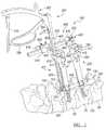
- FIG. 1is a perspective view of an exemplary percutaneous instrument assembly according to the present teachings shown in reference with two adjacent vertebrae;
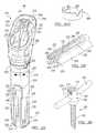
- FIG. 2Ais a perspective view of an exemplary percutaneous tower according to the present teachings, shown with a locking element;
- FIG. 2 A 1is a perspective view of the locking element of FIG. 2A ;
- FIG. 2Bis a perspective view of a distal portion of the percutaneous tower of FIG. 2A ;
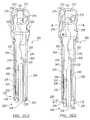
- FIG. 2 C 1is a perspective view of the percutaneous tower of FIG. 2A shown in a retracted position
- FIG. 2 D 1is a perspective view of the percutaneous tower of FIG. 2A shown in a extended position;
- FIG. 2 C 2is a partially cut-out view of the percutaneous tower of FIG. 2 C 1 ;
- FIG. 2 D 2is a partially cut-out view of the percutaneous tower of FIG. 2 D 1 ;
- FIG. 2Eis a perspective view of an exemplary outer elongated member of the percutaneous tower of FIG. 2A ;
- FIG. 2Fis a perspective view of an exemplary inner elongated member of the percutaneous tower of FIG. 2A ;
- FIG. 2Gis a perspective view of an exemplary flexible or pivotable bar of the percutaneous tower of FIG. 2A ;
- FIG. 2His a perspective view of an exemplary bone fastener shown with a connecting element according to the present teachings
- FIG. 2Iis an exploded view of the percutaneous tower of FIG. 2A ;
- FIG. 3Ais a top view of the percutaneous tower of FIG. 2A , shown with a channel divider in a closed position;
- FIG. 3Bis a top view of the percutaneous tower of FIG. 2A , shown with a channel divider in an open position;
- FIG. 3Cis a top view of the percutaneous tower of FIG. 2A shown with a tower connector of a compression/distraction mechanism according to the present teachings;
- FIG. 4Ais a partially exploded perspective view of an exemplary percutaneous instrument assembly according to the present teachings shown with two exemplary percutaneous towers and an exemplary compression-distraction mechanism;
- FIG. 4Bis an exploded view of an exemplary compression-distraction mechanism according to the present teachings.
- FIG. 5Aa top view of an exemplary percutaneous instrument assembly according to the present teachings shown with two exemplary percutaneous towers and an exemplary compression/distraction mechanism;
- FIG. 5Bis a side view of an exemplary percutaneous instrument assembly according to the present teachings illustrating an exemplary compression/distraction mechanism relative to vertebral bodies;
- FIG. 6Ais a top view of a portion of a percutaneous rod inserter before engaging or after releasing a connecting element according to the present teachings
- FIG. 6Bis a side view of a percutaneous rod inserter shown in engagement with a connecting element according to the present teachings
- FIG. 7Ais plan view of a connecting element according to the present teachings.
- FIG. 7Bis a side view of the connecting element of FIG. 7A ;
- FIG. 8Ais plan view of a percutaneous rod inserter shown with locking arms in engagement with a connecting element according to the present teachings
- FIG. 8Bis a plan view of a percutaneous rod inserter shown with locking arms disengaged from a connecting element according to the present teachings;
- FIG. 8Cis a side view of the percutaneous rod inserter and connecting element of FIG. 8A ;
- FIG. 8Dis a side view of the percutaneous rod inserter and connecting element of FIG. 8A , with the connecting element shown in an angled position;
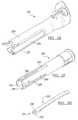
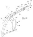
- FIG. 9Ais an exploded view of an exemplary percutaneous rod inserter according to the present teachings.
- FIG. 9Bis a perspective view of the percutaneous rod inserter of FIG. 9A shown with a connecting element in a first position;
- FIG. 9Cis a perspective view of the percutaneous rod inserter of FIG. 9A shown with a connecting element in a second angled position;
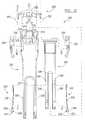
- FIG. 10is a side view of an exemplary percutaneous instrument assembly according to the present teachings illustrating a percutaneous rod inserter guiding a connecting element through a channel of a percutaneous tower connected to a vertebral body;
- FIG. 11is an exploded view of an exemplary fastener inserter according to the present teachings.
- FIG. 11Ais perspective view of the fastener inserter of FIG. 11 shown assembled through a percutaneous tower according to the present teachings;
- FIG. 12is an environmental view of a connecting element and two bone fasteners implanted in a spine according to the present teachings
- FIG. 13is a perspective view of an exemplary percutaneous instrument assembly according to the present teachings shown with three exemplary percutaneous towers and an exemplary compression-distraction mechanism;
- FIG. 14is a plan view of the percutaneous instrument assembly of FIG. 13 ;
- FIG. 15is a side view of the percutaneous instrument assembly of FIG. 13 ;
- FIG. 16is a perspective view of the middle tower of the percutaneous instrument assembly of FIG. 13 ;
- FIG. 17is a perspective view of an auxiliary arm of the percutaneous instrument assembly of FIG. 13 .
- an exemplary percutaneous instrument assembly 100can generally include one or more percutaneous towers 200 , a percutaneous rod or connecting element inserter 300 , and a compression/distraction mechanism 400 .
- various other instrumentssuch as tissue separators, drills, distractors, cannulas, guide wires, bone or pedicle screw inserters, or other instruments can be used in association with the percutaneous instrument assembly 100 at the discretion of the operating surgeon.
- the percutaneous instrument assembly 100can be used as a spine hardware delivery system that can provide a minimally invasive approach for spine fusion procedures, static or dynamic spine stabilization, or other orthopedic procedures.
- the percutaneous towers 200 of the percutaneous instrument assembly 100can be used to implant or remove bone or pedicle screws, bone anchors, or other bone fasteners 102 into the vertebral bodies 80 of the spine.
- the percutaneous towers 200can also be used to advance a percutaneous connecting element 104 , such as a connecting rod or bar or other elongated element, using the percutaneous rod inserter 300 .
- the targeted pediclescan be located and marked on the patient's skin.
- a percutaneous skin incision and fascia release in the form of a small portalcan be made with a knife blade, a Jamshidi-type needle, or other cutting instrument at the location marks on the patient's skin and a needle or similar instrument can be advanced through the skin incision.
- the needlecan be docked onto the targeted pedicle and verified with fluoroscopic imaging. Once trajectory and docking of the needle is confirmed and complete, the needle can be removed and replaced by guide wire.
- Dilation of the opening of the incision through the musclescan be performed, for example, in a two-staged sequential manner over the guide wire.
- a cannulated tapcan be advanced over the guide wire and the pedicle can be prepared for the implantation of a cannulated bone anchor, such as the bone fastener 102 .
- the bone fastener 102can then be assembled onto the distal end of the percutaneous tower 200 .
- each percutaneous tower 200can include an outer elongated member or outer shaft 202 and an inner elongated member or inner shaft 204 .
- the outer and inner elongated members 202 , 204can be coupled for allowing limited sliding relative to one another providing quick connection or disconnection for a fastener engagement member 230 that can be used to secure the bone fastener 102 to the percutaneous tower 200 without requiring additional locks or manipulating steps.
- quick disconnectioncan be effected through manual depression of a release actuator feature of the tower 200 in the direction of arrows “A”.
- one or more release buttons 206can be simultaneously depressed, thereby allowing the bone fastener 102 to be released, as described below.
- the release buttons 206are pivotably coupled to the proximal portions of the outer elongated member 202 , such that the inner elongated member 204 can move relative to the outer elongated member 202 from a first “retracted” position shown in FIGS. 2 C 1 and 2 C 2 in which the fastener engagement member 230 is in an engagement configuration relative to the bone fastener 102 , to a second “extended” position, shown in FIGS. 2 D 1 and 2 D 2 downwardly translated in the direction of arrow “B”, in which the fastener engagement member 230 is in a disengagement configuration relative to the bone fastener 102 .
- the percutaneous towercan include a locking element 600 for locking the release buttons 206 and preventing their accidental depression.
- the locking element 600can be in the form of a split ring or other U-shaped element.
- the locking element 600can be fitted over the outer elongated member 202 as shown in FIG. 2A .
- the locking element 600can include two pockets, cutouts or other openings 602 .
- the openings 602can be configured to allow pivoting of the release buttons 206 in the unlocked position.
- the distal ends of the release buttons 206can swing outward relative to the tower 200 through the openings 602 of the locking element 600 in the unlocked position of the locking element 600 .
- the locking element 600can be rotated from the unlocked position to a locked position in which the release buttons 206 can be prevented from pivoting, such that the distal ends of the release buttons 206 can be prevented from swinging out relatively to the tower 200 .
- the fastener engagement member 230can include two elements in the form of one or more flexible (elastically deflectable) or pivotable bars 232 that can engage respective opposing slots 208 of the inner elongated member 204 .
- the bars 232can be held between the outer and inner elongated members 202 , 204 against outward bias.
- Each bar 232can include a tab 234 and a protrusion 236 at opposite ends of its distal end 231 .
- the tabs 234are held inwards by the outer elongated member 202 , such that the protrusions 236 extend transversely into a first longitudinal opening, hole or channel 210 , which extends along a first longitudinal axis L 1 of the tower 200 .
- the longitudinal axis L 1 of the tower 200can pass through the proximal portion of the associated bone fastener 102 .
- the protrusions 236can engage corresponding engagement slots 108 in a receiver portion 106 of the bone fastener 102 , shown in FIG. 2H , as described below.
- the tabs 234move outwards in the direction of arrows “C” protruding out of the slots 208 of the inner elongated member 204 and becoming disengaged from the engagement slots 108 of the receiver portion 106 of the bone fastener 102 .
- the bone fastener 102can be held by either the outer elongated member 202 or the inner elongated member 204 at the distal end of the tower 200 .
- Each tower 200can at least partially define or include the first channel 210 discussed above and a second channel 212 which extends along a second axis L 2 .
- the first channel 210can extend from a curved opening 214 at a proximal end 215 of the outer elongated member 202 through a common bore 216 of the outer and inner elongated members 202 , 204 to an opening 218 at a distal end 220 of the tower 200 .
- the second channel 212can communicate with the first channel 210 .
- the second channel 212can be offset from the first channel 210 in a direction transverse to the first axis L 1 such that the axes L 1 and L 2 are parallel, but not coinciding.
- the second channel 212is formed in an angled portion 217 of the proximal end 215 and includes an offset opening 213 , which can extend from the curved opening 214 in a U-shape form. It another aspect, the second channel 212 can be angled and such that the second axis L 2 coincides with the first axis L 1 .
- the first and second channels 210 , 212can be used to support or pass various instruments and implants, such as, for example, an elongated distal portion 301 of the percutaneous rod inserter 300 , the connecting element 104 , as shown in FIGS. 1 and 10 , tower connectors 408 of the compression/distraction mechanism 400 , a bone fastener inserter 500 , as shown in FIG. 11A , and other instruments and implants, as discussed below.
- various instruments and implantssuch as, for example, an elongated distal portion 301 of the percutaneous rod inserter 300 , the connecting element 104 , as shown in FIGS. 1 and 10 , tower connectors 408 of the compression/distraction mechanism 400 , a bone fastener inserter 500 , as shown in FIG. 11A , and other instruments and implants, as discussed below.
- a spring-loaded channel divider 250can be coupled to the proximal end 215 of the outer elongated member 202 .
- the channel divider 250can function to selectively and optionally separate the first and second channels 210 , 212 .
- the channel divider 250can include a base 254 slidably coupled to the proximal end 215 , and two arms 252 pivotably coupled to the base 254 .
- the base 254can be moved between first and second positions as shown in FIGS. 3A and B. In the first position, shown in FIG.
- the arms 252are forced closer to each other, such that end portions of the arms 252 extend between the first and second channels 210 , 212 , keeping the first and second channels 210 , 212 separated.
- the arms 252spring outwards away from the openings of the first and second channels 210 , 212 to allow instruments and implants to pass freely between the first and second channels 210 , 212 .
- each tower 200can also have first and second longitudinal slots 221 , 223 defined by corresponding first and second slots 224 , 222 in the outer elongated member 202 and first and second slots 248 , 246 in the inner elongated member 204 .
- the first slot 221can be longer and can be placed on the side of the angled portion 217 of the tower 200 to provide additional space for instrumentation.
- the second slot 223can be shorter and can be placed opposite the first slot 221 for guiding the connecting element 104 as it exits or enters one of the towers 200 .
- the first and second slots 224 , 222 of the outer elongated member 202define first and second opposing legs 226 , 228 at the distal end of the outer elongated member 202 .
- the first and second slots 248 , 246 of the inner elongated member 204define first and second opposing legs 242 , 240 at the distal end of the inner elongated member 204 .
- the C/D mechanism 400can include a dial-type linear control 421 and a dial-type rotational control 423 .
- the linear control and the rotational controlcan include corresponding gear mechanisms coupled to a rack 402 of the C/D mechanism for providing mechanical advantage.
- the linear control 421can adjust the distance between the percutaneous towers 200
- the rotational control 423can adjust the angle of the towers 200 relative to each other and to the patient.
- the linear control 421 of the C/D mechanism 400can also determine the distance between the percutaneous towers 200 , and therefore it can be used to determine the length of the connecting element 104 that is required for a particular surgical procedure.
- the C/D mechanism 400can be provided with indicia representative of a distance between the associated bone fasteners 102 .
- a mathematical formula based on the geometric relation and the relative angles of the towers 200can be used to determine the appropriate length of the connecting element 104 .
- the C/D mechanism 400can include a rack 402 and first and second arms 404 , 406 , each of the arms 404 , 406 coupled to a tower connector 408 .
- the first arm 404can slide along the rack 402 in the direction of the straight arrows “T”.
- the second arm 406can be fixed relative to the rack 402 and can rotate about its axis “A 1 ” such that the tower connector 408 that is attached to the second arm 406 can angulate relative to the rack 402 and relative to the tower connector 408 that is connected to the first arm 404 in the directions shown by the curved arrows “R” in FIG. 5B .
- Each tower connector 408can be configured to be received in the proximal portion of the tower 200 and can include first and second channels 413 , 415 channels similar to the first and second channels 210 , 212 of the tower 200 enabling the instruments and implants to pass freely through both devices.
- Each tower connector 408can include a key feature 409 , which is configured to complement the angled portion 217 of the proximal end 215 of the tower 200 .
- the key feature 409prevents rotation of the tower connector 408 relative to the tower 200 and allows coupling in only one direction.
- the tower connector 408can also include a quick-connect, button-style mechanism 412 having a tab 411 that can engage an internal groove 205 of the release button 206 of the tower 200 (shown in FIG. 2I ).
- the tower connector 408When the tower connector 408 is attached to the tower 200 , the tower connector 408 can act as a safety lock, similarly to the locking element 600 , pushing against the inner surfaces of the release buttons 206 and preventing activation of the release buttons 206 , thereby preventing accidental release of the bone fastener 102 from the tower 200 .
- the C/D mechanism 400can include a directional lock 424 , which can be a knob with first and second settings.
- the first arm 404can be moved along the rack 402 bringing the first and second arms 404 , 406 and the corresponding tower connectors 408 closer to one another for compression.
- the first arm 404can be moved along the rack 402 to position the first and second arms 404 , 406 and the corresponding tower connectors 408 further apart relative to one another for distraction.
- a lock release control 418can be provided and operate to incapacitate the directional lock 424 , such that the first arm 404 is free to move in either direction for compression or distraction.
- the C/D mechanism 400can include an angulation control 422 which can be rotated to rotate the second arm 406 about its axis A 1 causing the respective tower 200 to angulate in the direction of the arrows R towards or away from the tower 200 that is coupled to the first arm 404 , as illustrated in FIG. 5B .
- the multilevel percutaneous instrument assembly 100can include in addition to the two end towers 200 as described above, one or more intermediate towers 200 a positioned between the end towers 200 .
- the end towers 200 and the intermediate towers 200 acan be coupled to and aligned with the C/D mechanism 400 .
- the rack 402 of the C/D mechanismcan be curved and of sufficient length for allowing the towers 200 , 200 a to follow the contour of the curved connecting element 104 , which can be longer for multilevel spinal procedures involving more than two adjacent vertebrae 80 .
- like references numbersare used to reference like elements, and their description is not repeated.
- the intermediate towers 200 acan be similar to the end towers 200 having a first channel 210 , but without the angled portion 212 and corresponding second channel 212 of the end towers 200 , as shown in FIG. 16 .
- the intermediate tower 200 acan be connected to curved rack 402 by an intermediate or auxiliary arm 405 , illustrated in FIG. 17 .
- the intermediate arm 405can include a central portion 406 c with first and second ends 405 a , 405 b .
- a rack connector 405 d associated with the second end 405 bcan be adapted to couple to the rack 402 , as shown in FIGS. 13-15 .
- the connector 405 dcan be in the form of a U-shaped sliding channel, as shown in FIG.
- a tower connector 408 acan be used to connect the intermediate tower 200 a to the auxiliary arm 405 .
- the tower connector 408 acan also operate as a locking element, similar to the locking element 600 discussed above with reference to FIGS. 2 A and 2 A 1 .
- the tower connector 408 acan include a planar ring 413 having an opening 413 c , and two opposing flanges 413 a , 413 b perpendicular to the ring 413 , as shown in FIG. 17 .
- the intermediate tower 200 acan be received in the opening 413 c of the ring 413 , and the flanges 413 a , 413 b can provide the locking function preventing accidental release of the bone fastener 102 , by preventing accidental actuation of the release buttons 206 .
- the rack connector 405 dcan include a sliding motion control 421 to couple the auxiliary arm 405 to the rack 402 .
- the sliding motion control 421 of the rack connector 405can be similar to the linear control 421 described above in reference to FIGS. 4A-5B .
- Other rack-and-pinion or gear mechanisms enabling the auxiliary arm 405 to travel along the curved rack 402can also be used.
- the rack connector 405 dcan also include a rotational control, similar to the rotational control 423 , and enabling the auxiliary arm 405 to angulate from side to side in a similar way as illustrated by arrows R in connection with the end tower 200 in FIG. 5B .
- the rack connector 405 dcan also incorporate a gear system allowing the auxiliary arm 405 to rotate relative to the rack in an upward-downward motion.
- the rack and pinion or gear operated controls of the auxiliary arm 405 and the similar controls of the first and second arms 404 , 406can provide incremental and gradual control of the relative position of the towers 200 , 200 a so that the bone fasteners 102 can be moved more precisely and over a longer time period allowing the body to adjust to the changes.
- each of the end towers 200can be coupled to the corresponding tower connector 408 of the C/D mechanism 400 with a connecting member 251 which can be released with pin-type or other elements 401 .
- Similar connecting elements 401can be used as pivots or connecting pins for various tower components.
- the multilevel percutaneous instrument assembly illustrated in FIGS. 13-17can be used to align the bone fasteners 102 and have the ability to compress or distract or generally manipulate adjacent pairs of vertebrae 80 at each level.
- the gear mechanisms incorporated in the sliding motion control 421 and rotational control 423can provide mechanical advantage and incremental control of the relative movement of the towers 1200 , 200 a and the associated bone fasteners 102 .
- Additional auxiliary arms 405 and intermediate towers 200 acan be added as needed to accommodate additional levels of vertebrae.
- the rod inserter 300is illustrated in exemplary positions relative to the connecting element 104 .
- the rod inserter 300can include a rongeur-type body 302 including a rack bar 310 , an angle handle 308 that can be coupled to various positions along the rack bar 310 , a release trigger 306 , and an elongated distal portion 301 insertable through the first 210 or second channel 212 of the tower 200 .
- the elongated distal portion 301can include mechanisms for releasably coupling the connecting element 104 to the rod inserter 300 , such that the connecting element 104 can be held in a first position in which a longitudinal axis “E” of the connecting element 104 is substantially parallel or coaxial to a longitudinal axis “D” of the elongated distal portion 301 of the rod inserter 300 , as shown in FIGS. 8C and 9B , and in a second position in which the connecting element 104 is at an angle ⁇ relative to the elongated distal portion 301 of the rod inserter, as shown in FIGS. 8D and 9C .
- the angle handle 308can be operably coupled to an angle arm 304 that can include a U-shaped distal portion 312 adapted to pivotable engage an open slot 142 in the proximal end of the connecting element 104 . Pressing the angle handle 308 in the direction of arrow “G 2 ” causes the angle arm 304 to move forward in the direction of arrow “H 2 ” and urges the connecting element 104 to pivot at an angled position relative to the elongated distal portion 301 of the percutaneous rod inserter 300 , as shown in FIGS. 9C and 8D .
- the release trigger 306can be operably coupled to a shaft 316 coupled to a pair of pivotable locking arms 314 , shown in FIGS. 8A , 8 B and 9 A.
- the locking arms 314can be biased to remain in the close position illustrated in FIG. 9B , and can be pivoted to an open position by pressing the release trigger 306 in the direction of arrow “K”, as shown in FIG. 9C .
- the locking arms 314can be L-shaped and have end portions 315 that can pass through a hole 144 defined in a proximal end 140 of the connecting element 104 when the locking arms 314 are in their closed position, as shown in FIGS. 8A and 9B .
- a safety lock 318can be placed in the lock position indicated by arrow “I 1 ” in FIG.
- the connecting element 104can be released from the rod inserter 300 by placing the safety lock 318 in the open position indicated by arrow “I 2 ” in FIG. 9C , and pulling the release trigger 306 in the direction of the arrow K. While holding the locking arms 314 in the open position, the distal portion 312 of the angle arm 304 can be pushed out of the slot 142 of the connecting element 104 .
- the connecting element 104can include a shaft 146 having a bullet-like or rounded conical distal tip 130 for guiding insertion through tissue.
- a groove 132 behind the distal tip 130can show the location of the distal tip 130 under fluoroscopy.
- the connecting element 104can include two rounded protrusions 148 between flat portions 141 near the proximal end 140 for holding that portion of the connecting element 104 within the receiver portion 106 of the bone fastener 102 .
- the shaft 146 of the connecting element 104can have a curved portion for following the natural anatomy of the spine.
- the bone fastener 102can include a cannulated fastener shaft 103 that can be at least partially threaded.
- the shaft 103can be received through an opening of the receiver portion 106 of the bone fastener 102 .
- the receiver portion 106can be U-shaped and include two arms 112 that have partially threaded inner surfaces 105 .
- the fastener inserter 500can be cannulated and configured to fit over a guide wire 506 .
- the fastener inserter 500can include an inner shaft 502 having a proximal end 510 configured to be engaged with a driver and a distal tip 504 adapted to engage with a proximal end 111 of the fastener shaft 103 .
- the distal tip 504can be, for example, a lobed tip, such as a pentalobe tip, or have another shape that can mate with the distal end of the fastener shaft 103 .
- the fastener inserter 500can also include a tubular sleeve 508 over the inner shaft 502 .
- the tubular sleeve 508can rotate independently of the inner shaft 502 by rotating an enlarged proximal end 514 of the tubular sleeve 508 .
- the tubular sleeve 508can have a threaded distal end 509 that can be threaded onto threaded inner surfaces 105 of the receiver portion 106 to secure the fastener inserter 500 to the fastener 102 and the percutaneous tower 200 , as shown in FIG. 11A .
- the fastener inserter 500can also include an enlarged cylindrical portion 512 that can fit into the percutaneous tower 200 and prevent the release buttons 206 from pivoting to the unlocked position (proximal ends swinging in or distal end swinging out relative to the tower 200 ), thus preventing release of the bone fastener 102 .
- the percutaneous tower 200 with the bone fastener 102 and the faster inserter 500 assembled thereon, as described above,can be advanced under fluoroscopic imaging over the guide wire 506 to implant the bone fastener 102 through the pedicle and into the vertebral body 80 .
- the guide wire 506 and the fastener inserter 500can then be removed and the procedure repeated to implant another bone fastener 102 into another vertebral body 80 , such as an adjacent vertebral body 80 .
- the C/D mechanismcan be attached to the percutaneous towers 200 and adjust the distance between the percutaneous towers 200 as well as the angle of the towers 200 relative to each other, and therefore relative to the spine, as discussed above.
- the length of the connecting element 104 and the trajectory of the connecting element 104 from cephalad to caudal or from caudal to cephaladcan be determined.
- the connecting element 104can be advanced through the first channel 210 or the second channel 212 of one of the percutaneous towers 200 .
- the connecting element 104can be manipulated and gradually rotated relative to the percutaneous rod inserter 300 such that the connecting element 104 can pass through a slot of the first tower 200 , such as, for example the longer slot 221 of the first tower 200 (shown in FIG. 4A ).
- the connecting element 104can be further manipulated with the percutaneous rod inserter 300 directionally through tissue and rotationally through further angulation/rotation relative to the rod inserter 300 until the connecting element 104 can pass through a slot of the second tower 200 , such as, for example, the shorter slot 223 of the next tower 200 (shown in FIG. 4A ).
- the percutaneous rod inserter 300can be configured to allow freehand manipulation of the connecting element 104 along a variable-angle path that leads through tissue from one implanted bone fastener 102 to another implanted bone fastener 102 .
- the connecting element 104can thus be placed into the receiver portions 106 of the bone fasteners 102 .
- a fastener plug 110 having an external threaded portion 114can be inserted into one of the percutaneous towers 200 and threaded into the inner surface 105 of receiver portion 106 to capture the connecting element 104 between the fastener shaft 103 and the fastener plug 110 into the receiver portion 106 .
- the procedurecan be repeated for the other percutaneous tower 200 .
- the C/D mechanism 400 , the percutaneous rod inserter 300 , and the percutaneous towers 200can be removed, as shown in FIG. 12 and closure of the percutaneous operative site can be performed according to standard protocols and procedures.
- the present teachingcan be used in connection with single level spinal fusion or other spinal manipulation or procedure between two adjacent vertebrae, or between two vertebrae that are not adjacent. Further, the present teachings can be used for multiple-level procedures using more than two percutaneous towers 200 , 200 a and corresponding bone fasteners 102 . In this regard, the present teachings can be readily adapted to connect, for example, three or more vertebral bodies.
Landscapes
- Health & Medical Sciences (AREA)
- Orthopedic Medicine & Surgery (AREA)
- Neurology (AREA)
- Life Sciences & Earth Sciences (AREA)
- Surgery (AREA)
- Heart & Thoracic Surgery (AREA)
- Engineering & Computer Science (AREA)
- Biomedical Technology (AREA)
- Nuclear Medicine, Radiotherapy & Molecular Imaging (AREA)
- Medical Informatics (AREA)
- Molecular Biology (AREA)
- Animal Behavior & Ethology (AREA)
- General Health & Medical Sciences (AREA)
- Public Health (AREA)
- Veterinary Medicine (AREA)
- Surgical Instruments (AREA)
Abstract
Description
Claims (19)
Priority Applications (3)
| Application Number | Priority Date | Filing Date | Title |
|---|---|---|---|
| US11/737,819US8162952B2 (en) | 2006-09-26 | 2007-04-20 | Percutaneous instrument assembly |
| EP08754086AEP2148625A1 (en) | 2007-04-20 | 2008-04-15 | Percutaneous instrument assembly |
| PCT/US2008/004856WO2008130548A1 (en) | 2007-04-20 | 2008-04-15 | Percutaneous instrument assembly |
Applications Claiming Priority (2)
| Application Number | Priority Date | Filing Date | Title |
|---|---|---|---|
| US11/527,246US8038699B2 (en) | 2006-09-26 | 2006-09-26 | Percutaneous instrument assembly |
| US11/737,819US8162952B2 (en) | 2006-09-26 | 2007-04-20 | Percutaneous instrument assembly |
Related Parent Applications (1)
| Application Number | Title | Priority Date | Filing Date |
|---|---|---|---|
| US11/527,246Continuation-In-PartUS8038699B2 (en) | 2006-09-26 | 2006-09-26 | Percutaneous instrument assembly |
Publications (2)
| Publication Number | Publication Date |
|---|---|
| US20080077138A1 US20080077138A1 (en) | 2008-03-27 |
| US8162952B2true US8162952B2 (en) | 2012-04-24 |
Family
ID=39672596
Family Applications (1)
| Application Number | Title | Priority Date | Filing Date |
|---|---|---|---|
| US11/737,819Expired - Fee RelatedUS8162952B2 (en) | 2006-09-26 | 2007-04-20 | Percutaneous instrument assembly |
Country Status (3)
| Country | Link |
|---|---|
| US (1) | US8162952B2 (en) |
| EP (1) | EP2148625A1 (en) |
| WO (1) | WO2008130548A1 (en) |
Cited By (23)
| Publication number | Priority date | Publication date | Assignee | Title |
|---|---|---|---|---|
| US20110319938A1 (en)* | 2010-06-24 | 2011-12-29 | Warsaw Orthopedic, Inc. | Coplanar deformity correction system |
| US8784431B1 (en)* | 2012-06-11 | 2014-07-22 | Choice Spine, Lp | Medical screwdriver |
| US20150088210A1 (en)* | 2013-09-23 | 2015-03-26 | Stryker Spine | Lumbar-sacral screw insertion and manipulation |
| US9408716B1 (en) | 2013-12-06 | 2016-08-09 | Stryker European Holdings I, Llc | Percutaneous posterior spinal fusion implant construction and method |
| US9486257B2 (en) | 2014-08-07 | 2016-11-08 | Jeffrey Scott Smith | Rod reduction tool and method to assist in the passage of a connecting rod between pedicle screws |
| US9622795B2 (en) | 2013-12-13 | 2017-04-18 | Stryker European Holdings I, Llc | Tissue retraction and vertebral displacement devices, systems, and methods for posterior spinal fusion |
| US9681899B2 (en) | 2015-03-23 | 2017-06-20 | Globus Medical, Inc. | Orthopedic derotation devices and methods of installation thereof |
| US9744050B1 (en) | 2013-12-06 | 2017-08-29 | Stryker European Holdings I, Llc | Compression and distraction system for percutaneous posterior spinal fusion |
| US9750546B2 (en) | 2014-08-11 | 2017-09-05 | Spinal Elements, Inc. | Articulating rod inserter |
| US9844398B2 (en) | 2012-05-11 | 2017-12-19 | Orthopediatrics Corporation | Surgical connectors and instrumentation |
| US9907582B1 (en) | 2011-04-25 | 2018-03-06 | Nuvasive, Inc. | Minimally invasive spinal fixation system and related methods |
| US20180132911A1 (en)* | 2015-05-12 | 2018-05-17 | Shandong Weigao Orthopedic Device Company Ltd | Grasping end of frog-style forceps |
| US10159579B1 (en) | 2013-12-06 | 2018-12-25 | Stryker European Holdings I, Llc | Tubular instruments for percutaneous posterior spinal fusion systems and methods |
| US10779866B2 (en) | 2016-12-29 | 2020-09-22 | K2M, Inc. | Rod reducer assembly |
| US20210282820A1 (en)* | 2018-06-13 | 2021-09-16 | Nuvasive, Inc. | Rod Reduction Assemblies and Related Methods |
| US11123063B2 (en) | 2018-02-05 | 2021-09-21 | Lsi Solutions, Inc. | Apparatus for suture management and methods thereof |
| US20210322064A1 (en)* | 2020-04-16 | 2021-10-21 | Warsaw Orthopedic, Inc. | Systems, methods of use and surgical instruments employing a secure slide lock to fasten a head |
| US11350922B1 (en) | 2021-02-03 | 2022-06-07 | Warsaw Orthopedic, Inc. | Modular surgical instrument system and method for shank-based retraction and distraction |
| US11406431B1 (en) | 2021-05-10 | 2022-08-09 | Warsaw Orthopedic, Inc. | Systems and methods of use and modular instruments with a lateral reducer |
| US11432852B1 (en) | 2021-03-22 | 2022-09-06 | Warsaw Orthopedic, Inc. | Screw shank based tissue retraction |
| US11439442B2 (en)* | 2020-04-16 | 2022-09-13 | Warsaw Orthopedic, Inc. | Modular screw system with head locker and derotator |
| US11602379B2 (en) | 2015-03-23 | 2023-03-14 | Globus Medical, Inc. | Orthopedic derotation devices and methods of installation thereof |
| US11617603B2 (en) | 2020-12-09 | 2023-04-04 | Warsaw Orthopedic, Inc. | Modular surgical instrument system with ratcheting reduction mechanism |
Families Citing this family (120)
| Publication number | Priority date | Publication date | Assignee | Title |
|---|---|---|---|---|
| US7833250B2 (en) | 2004-11-10 | 2010-11-16 | Jackson Roger P | Polyaxial bone screw with helically wound capture connection |
| US7862587B2 (en) | 2004-02-27 | 2011-01-04 | Jackson Roger P | Dynamic stabilization assemblies, tool set and method |
| EP1417000B1 (en) | 2001-07-11 | 2018-07-11 | Nuvasive, Inc. | System for determining nerve proximity during surgery |
| JP2005503857A (en) | 2001-09-25 | 2005-02-10 | ヌバシブ, インコーポレイテッド | Systems and methods for performing surgical procedures and surgical diagnosis |
| US7582058B1 (en) | 2002-06-26 | 2009-09-01 | Nuvasive, Inc. | Surgical access system and related methods |
| US8876868B2 (en) | 2002-09-06 | 2014-11-04 | Roger P. Jackson | Helical guide and advancement flange with radially loaded lip |
| US8137284B2 (en) | 2002-10-08 | 2012-03-20 | Nuvasive, Inc. | Surgical access system and related methods |
| AU2003287273C1 (en) | 2002-10-30 | 2010-01-07 | Zimmer Spine, Inc. | Spinal stabilization system insertion and methods |
| US9539012B2 (en) | 2002-10-30 | 2017-01-10 | Zimmer Spine, Inc. | Spinal stabilization systems with quick-connect sleeve assemblies for use in surgical procedures |
| US7691057B2 (en) | 2003-01-16 | 2010-04-06 | Nuvasive, Inc. | Surgical access system and related methods |
| US7621918B2 (en) | 2004-11-23 | 2009-11-24 | Jackson Roger P | Spinal fixation tool set and method |
| US7377923B2 (en) | 2003-05-22 | 2008-05-27 | Alphatec Spine, Inc. | Variable angle spinal screw assembly |
| US8366753B2 (en) | 2003-06-18 | 2013-02-05 | Jackson Roger P | Polyaxial bone screw assembly with fixed retaining structure |
| US8926670B2 (en) | 2003-06-18 | 2015-01-06 | Roger P. Jackson | Polyaxial bone screw assembly |
| US7776067B2 (en) | 2005-05-27 | 2010-08-17 | Jackson Roger P | Polyaxial bone screw with shank articulation pressure insert and method |
| US7967850B2 (en) | 2003-06-18 | 2011-06-28 | Jackson Roger P | Polyaxial bone anchor with helical capture connection, insert and dual locking assembly |
| US7766915B2 (en) | 2004-02-27 | 2010-08-03 | Jackson Roger P | Dynamic fixation assemblies with inner core and outer coil-like member |
| JP4463819B2 (en) | 2003-09-25 | 2010-05-19 | ヌヴァシヴ インコーポレイテッド | Surgical access system |
| US7905840B2 (en) | 2003-10-17 | 2011-03-15 | Nuvasive, Inc. | Surgical access system and related methods |
| US7527638B2 (en) | 2003-12-16 | 2009-05-05 | Depuy Spine, Inc. | Methods and devices for minimally invasive spinal fixation element placement |
| US11419642B2 (en) | 2003-12-16 | 2022-08-23 | Medos International Sarl | Percutaneous access devices and bone anchor assemblies |
| US7179261B2 (en) | 2003-12-16 | 2007-02-20 | Depuy Spine, Inc. | Percutaneous access devices and bone anchor assemblies |
| US8152810B2 (en) | 2004-11-23 | 2012-04-10 | Jackson Roger P | Spinal fixation tool set and method |
| US11241261B2 (en) | 2005-09-30 | 2022-02-08 | Roger P Jackson | Apparatus and method for soft spinal stabilization using a tensionable cord and releasable end structure |
| JP2007525274A (en) | 2004-02-27 | 2007-09-06 | ロジャー・ピー・ジャクソン | Orthopedic implant rod reduction instrument set and method |
| US7160300B2 (en) | 2004-02-27 | 2007-01-09 | Jackson Roger P | Orthopedic implant rod reduction tool set and method |
| US7651502B2 (en) | 2004-09-24 | 2010-01-26 | Jackson Roger P | Spinal fixation tool set and method for rod reduction and fastener insertion |
| US8926672B2 (en) | 2004-11-10 | 2015-01-06 | Roger P. Jackson | Splay control closure for open bone anchor |
| US9168069B2 (en) | 2009-06-15 | 2015-10-27 | Roger P. Jackson | Polyaxial bone anchor with pop-on shank and winged insert with lower skirt for engaging a friction fit retainer |
| US8444681B2 (en) | 2009-06-15 | 2013-05-21 | Roger P. Jackson | Polyaxial bone anchor with pop-on shank, friction fit retainer and winged insert |
| WO2006057837A1 (en) | 2004-11-23 | 2006-06-01 | Jackson Roger P | Spinal fixation tool attachment structure |
| US7901437B2 (en) | 2007-01-26 | 2011-03-08 | Jackson Roger P | Dynamic stabilization member with molded connection |
| US9314273B2 (en) | 2005-04-27 | 2016-04-19 | Globus Medical, Inc. | Percutaneous vertebral stabilization system |
| US7955358B2 (en) | 2005-09-19 | 2011-06-07 | Albert Todd J | Bone screw apparatus, system and method |
| US8038699B2 (en) | 2006-09-26 | 2011-10-18 | Ebi, Llc | Percutaneous instrument assembly |
| US8162952B2 (en) | 2006-09-26 | 2012-04-24 | Ebi, Llc | Percutaneous instrument assembly |
| CA2670988C (en) | 2006-12-08 | 2014-03-25 | Roger P. Jackson | Tool system for dynamic spinal implants |
| US8979904B2 (en) | 2007-05-01 | 2015-03-17 | Roger P Jackson | Connecting member with tensioned cord, low profile rigid sleeve and spacer with torsion control |
| US20090082811A1 (en)* | 2007-09-26 | 2009-03-26 | Depuy Spine, Inc. | Devices and methods for positioning a spinal fixation element |
| US8439922B1 (en) | 2008-02-06 | 2013-05-14 | NiVasive, Inc. | Systems and methods for holding and implanting bone anchors |
| US8226656B2 (en) | 2008-04-16 | 2012-07-24 | Warsaw Orthopedic, Inc. | Minimally invasive systems and methods for insertion of a connecting member adjacent the spinal column |
| AU2010260521C1 (en) | 2008-08-01 | 2013-08-01 | Roger P. Jackson | Longitudinal connecting member with sleeved tensioned cords |
| WO2010045383A2 (en) | 2008-10-14 | 2010-04-22 | Trinity Orthopedics, Llc | Insertion and reduction tool for pedicle screw assembly |
| ES2477417T3 (en)* | 2008-10-23 | 2014-07-16 | Alphatec Spine, Inc. | Fixation systems for the spine |
| US8496661B2 (en)* | 2008-11-03 | 2013-07-30 | Omni Surgical LLC | System and method for micro-invasive transfacet lumbar interbody fusion |
| US9750545B2 (en)* | 2009-03-27 | 2017-09-05 | Globus Medical, Inc. | Devices and methods for inserting a vertebral fixation member |
| US8900238B2 (en)* | 2009-03-27 | 2014-12-02 | Globus Medical, Inc. | Devices and methods for inserting a vertebral fixation member |
| CN103826560A (en) | 2009-06-15 | 2014-05-28 | 罗杰.P.杰克逊 | Polyaxial Bone Anchor with Socket Stem and Winged Inserts with Friction Fit Compression Collars |
| US8998959B2 (en) | 2009-06-15 | 2015-04-07 | Roger P Jackson | Polyaxial bone anchors with pop-on shank, fully constrained friction fit retainer and lock and release insert |
| US9668771B2 (en) | 2009-06-15 | 2017-06-06 | Roger P Jackson | Soft stabilization assemblies with off-set connector |
| US11229457B2 (en) | 2009-06-15 | 2022-01-25 | Roger P. Jackson | Pivotal bone anchor assembly with insert tool deployment |
| US8246624B2 (en)* | 2009-07-23 | 2012-08-21 | Zimmer Spine, Inc. | Spinal rod insertion tool and method |
| US9655658B2 (en) | 2009-10-14 | 2017-05-23 | Ebi, Llc | Deformable device for minimally invasive fixation |
| US20110093014A1 (en)* | 2009-10-19 | 2011-04-21 | Zimmer Spine, Inc. | Rod with Removable End and Inserter Therefor |
| US9044272B2 (en) | 2009-11-09 | 2015-06-02 | Ebi, Llc | Multiplanar bone anchor system |
| US8449578B2 (en)* | 2009-11-09 | 2013-05-28 | Ebi, Llc | Multiplanar bone anchor system |
| DE112010004338B4 (en) | 2009-11-10 | 2019-06-27 | Nuvasive, Inc. | DEVICE FOR IMPLEMENTING SPINE SURGERY |
| US8647370B2 (en)* | 2010-01-15 | 2014-02-11 | Ebi, Llc | Uniplanar bone anchor system |
| US8419778B2 (en) | 2010-01-15 | 2013-04-16 | Ebi, Llc | Uniplanar bone anchor system |
| US8636655B1 (en) | 2010-01-19 | 2014-01-28 | Ronald Childs | Tissue retraction system and related methods |
| US8460301B2 (en)* | 2010-01-27 | 2013-06-11 | Warsaw Orthopedic, Inc. | Systems and methods for minimally invasive stabilization of bony structures |
| US8540719B2 (en) | 2010-02-09 | 2013-09-24 | Aesculap Implant Systems, Llc | Percutaneous rod insertion system and method |
| US8628535B2 (en) | 2010-05-14 | 2014-01-14 | Beacon Biomedical, Llc | Bone fixation rod and implantation device for insertion thereof |
| EP2600782B1 (en) | 2010-08-02 | 2016-03-16 | Synthes GmbH | Orthopedic implant system |
| WO2012045070A1 (en) | 2010-10-01 | 2012-04-05 | K2M, Inc. | Devices, systems, and methods for performing spinal surgery |
| CN102028533B (en)* | 2011-01-13 | 2013-04-17 | 邱勇 | Spinal deformation correcting device |
| US9198698B1 (en) | 2011-02-10 | 2015-12-01 | Nuvasive, Inc. | Minimally invasive spinal fixation system and related methods |
| US8790406B1 (en) | 2011-04-01 | 2014-07-29 | William D. Smith | Systems and methods for performing spine surgery |
| US8414590B2 (en)* | 2011-04-14 | 2013-04-09 | Custom Spine, Inc. | Pivoting insertion apparatus and method |
| USD649243S1 (en) | 2011-05-05 | 2011-11-22 | Ebi, Llc | Pusher for a rod reduction device |
| US9307972B2 (en) | 2011-05-10 | 2016-04-12 | Nuvasive, Inc. | Method and apparatus for performing spinal fusion surgery |
| US9204909B2 (en) | 2011-07-13 | 2015-12-08 | Warsaw Orthopedic, Inc. | Spinal rod system and method |
| US8911442B2 (en)* | 2011-10-26 | 2014-12-16 | Alphatec Spine, Inc. | Systems for vertebral adjustments and rod reduction |
| US8951257B2 (en)* | 2012-02-15 | 2015-02-10 | Warsaw Orthopedic, Inc. | Spinal correction system and method |
| US8936626B1 (en) | 2012-02-17 | 2015-01-20 | Nuvasive, Inc. | Bi-cortical screw fixation |
| US20130317557A1 (en)* | 2012-05-26 | 2013-11-28 | Custom Spine, Inc. | Mis rod insertion device and method |
| US9011450B2 (en) | 2012-08-08 | 2015-04-21 | DePuy Synthes Products, LLC | Surgical instrument |
| US8911478B2 (en) | 2012-11-21 | 2014-12-16 | Roger P. Jackson | Splay control closure for open bone anchor |
| WO2014089467A1 (en)* | 2012-12-06 | 2014-06-12 | In Queue Innovations, Llc | Minimally invasive spinal column realignment system and method |
| US10058354B2 (en) | 2013-01-28 | 2018-08-28 | Roger P. Jackson | Pivotal bone anchor assembly with frictional shank head seating surfaces |
| US8852239B2 (en) | 2013-02-15 | 2014-10-07 | Roger P Jackson | Sagittal angle screw with integral shank and receiver |
| WO2014134534A2 (en)* | 2013-02-28 | 2014-09-04 | Alphatec Spine, Inc. | Spinal deformity correction instruments and methods |
| US20140257416A1 (en)* | 2013-03-06 | 2014-09-11 | Nathan Meyer | Percutaneous rod inserter |
| US9387018B2 (en)* | 2013-03-14 | 2016-07-12 | Warsaw Orthopedic, Inc. | Surgical implant system and method |
| US9241742B2 (en) | 2013-03-14 | 2016-01-26 | DePuy Synthes Products, Inc. | Methods and devices for polyaxial screw alignment |
| CA2846149C (en)* | 2013-03-14 | 2018-03-20 | Stryker Spine | Systems and methods for percutaneous spinal fusion |
| US9668789B2 (en) | 2013-03-15 | 2017-06-06 | Ebi, Llc | Reduction instrument, surgical assembly including a reduction instrument and related method |
| US9173687B2 (en)* | 2013-03-15 | 2015-11-03 | DePuy Synthes Products, Inc. | Fulcrum cap for spinal constructs |
| US20150073485A1 (en)* | 2013-09-09 | 2015-03-12 | Warsaw Orthopedic, Inc. | Surgical instrument and method |
| US9526536B2 (en)* | 2013-10-16 | 2016-12-27 | Spineology Inc. | Articulating rod holder |
| US9566092B2 (en) | 2013-10-29 | 2017-02-14 | Roger P. Jackson | Cervical bone anchor with collet retainer and outer locking sleeve |
| EP2881052A1 (en)* | 2013-12-09 | 2015-06-10 | Biedermann Technologies GmbH & Co. KG | Rod insertion device for inserting a rod into a bone anchor, in particular for minimally invasive surgery |
| US9717533B2 (en) | 2013-12-12 | 2017-08-01 | Roger P. Jackson | Bone anchor closure pivot-splay control flange form guide and advancement structure |
| US9451993B2 (en) | 2014-01-09 | 2016-09-27 | Roger P. Jackson | Bi-radial pop-on cervical bone anchor |
| US9597119B2 (en) | 2014-06-04 | 2017-03-21 | Roger P. Jackson | Polyaxial bone anchor with polymer sleeve |
| US10064658B2 (en) | 2014-06-04 | 2018-09-04 | Roger P. Jackson | Polyaxial bone anchor with insert guides |
| US9795370B2 (en) | 2014-08-13 | 2017-10-24 | Nuvasive, Inc. | Minimally disruptive retractor and associated methods for spinal surgery |
| US9968394B2 (en)* | 2015-06-01 | 2018-05-15 | Alphatec Spine, Inc. | Instrument for removing tabs from a reduction screw |
| ZA201603814B (en)* | 2015-06-04 | 2019-08-28 | Minimal Invasive Tech Pty Ltd | Pedicle mountable retractor system |
| WO2017059375A1 (en)* | 2015-09-30 | 2017-04-06 | Beacon Biomedical, Llc | Surgical instrument for implant insertion |
| US20190336182A1 (en) | 2015-10-27 | 2019-11-07 | Ctl Medical Corporation | Modular rod reduction tower and related methods |
| US20170112551A1 (en)* | 2015-10-27 | 2017-04-27 | Ctl Medical Corporation | Modular rod reduction tower and related methods |
| US20170143385A1 (en)* | 2015-11-19 | 2017-05-25 | K2M, Inc. | Spinal rod reduction system |
| US9795422B2 (en)* | 2016-01-06 | 2017-10-24 | Aesculap Implant Systems, Llc | Rod inserter, system and method |
| US10085778B2 (en) | 2016-03-04 | 2018-10-02 | Spinal Elements, Inc. | Rod reducer instrument for spinal surgery |
| DE102016011521A1 (en) | 2016-09-23 | 2018-03-29 | Silony Medical International AG | Stabeinbringinstrument with adjustable rod angulation |
| US11154336B2 (en)* | 2016-12-06 | 2021-10-26 | Marc J. LEVINE | Retractor/compression/distraction system |
| WO2018150214A1 (en)* | 2017-02-17 | 2018-08-23 | Warsaw Orthopedic, Inc. | Surgical system |
| CA3073564C (en) | 2017-08-29 | 2022-10-18 | Zimmer Biomet Spine, Inc. | Surgical cord tensioning devices, systems, and methods |
| US10939941B2 (en) | 2017-08-29 | 2021-03-09 | Zimmer Biomet Spine, Inc. | Surgical cord tensioning devices, systems, and methods |
| US10610269B2 (en)* | 2017-09-05 | 2020-04-07 | Medos International Sarl | Modular surgical instruments and related methods |
| EP3517062B1 (en)* | 2018-01-26 | 2021-03-17 | Aesculap AG | Spinal repositioning instrument and spinal repositioning system |
| WO2020068883A1 (en)* | 2018-09-24 | 2020-04-02 | Astura Medical Inc. | Mis multi-level compressor / distractor |
| US10799300B2 (en)* | 2018-10-18 | 2020-10-13 | Warsaw Orthopedic, Inc. | Spinal implant system and method |
| CN110731803B (en)* | 2019-11-20 | 2021-05-25 | 吕振乾 | Heart surgical operation assistor |
| US12193711B2 (en)* | 2020-12-17 | 2025-01-14 | Md Antonacci Family Trust | Method for improved spinal correction surgery implementing non-fusion anterior scoliosis correction techniques |
| US11389204B2 (en)* | 2020-12-17 | 2022-07-19 | Institute For Spine & Scoliosis, P.A. | Method for improved spinal correction surgery implementing non-fusion anterior scoliosis correction techniques for release of discs |
| JP2024508548A (en) | 2021-03-05 | 2024-02-27 | メドス・インターナショナル・エスエイアールエル | sequential reducer |
| US12324610B2 (en) | 2021-04-28 | 2025-06-10 | Spinal Elements, Inc. | Lever reducer |
| US20240260998A1 (en)* | 2023-02-08 | 2024-08-08 | Orthopediatrics Corp. | Coupling sleeve for bone power tool |
Citations (88)
| Publication number | Priority date | Publication date | Assignee | Title |
|---|---|---|---|---|
| US4386603A (en) | 1981-03-23 | 1983-06-07 | Mayfield Jack K | Distraction device for spinal distraction systems |
| US4733657A (en) | 1984-04-16 | 1988-03-29 | Patrick Kluger | Apparatus for aligning a spinal column having damaged vertebrae |
| US4926849A (en) | 1986-12-19 | 1990-05-22 | Downey Ernest L | Apparatus for separating vertebrae |
| US4957495A (en) | 1987-04-01 | 1990-09-18 | Patrick Kluger | Device for setting the spinal column |
| US5219349A (en) | 1991-02-15 | 1993-06-15 | Howmedica, Inc. | Spinal fixator reduction frame |
| EP0553782A1 (en) | 1992-01-31 | 1993-08-04 | Kluger, Patrick, Dr. med. | Rachidial implant and reposition instrument |
| US5354292A (en) | 1993-03-02 | 1994-10-11 | Braeuer Harry L | Surgical mesh introduce with bone screw applicator for the repair of an inguinal hernia |
| US5728046A (en) | 1995-06-23 | 1998-03-17 | Aesculap Ag | Surgical retractor |
| US5785648A (en) | 1996-10-09 | 1998-07-28 | David Min, M.D., Inc. | Speculum |
| US6090113A (en)* | 1996-12-27 | 2000-07-18 | Stryker France S.A. | Adjustable osteosynthesis system of the rachis |
| US6123707A (en) | 1999-01-13 | 2000-09-26 | Spinal Concepts, Inc. | Reduction instrument |
| US6139549A (en) | 1996-04-09 | 2000-10-31 | Waldemar Link (Gmbh & Co.) | Spinal fixing device |
| US6159179A (en) | 1999-03-12 | 2000-12-12 | Simonson; Robert E. | Cannula and sizing and insertion method |
| US6287313B1 (en) | 1999-11-23 | 2001-09-11 | Sdgi Holdings, Inc. | Screw delivery system and method |
| US20020161368A1 (en) | 1999-10-20 | 2002-10-31 | Foley Kevin T. | Instruments and methods for stabilization of bony structures |
| US20030208203A1 (en) | 2002-05-06 | 2003-11-06 | Roy Lim | Minimally invasive instruments and methods for inserting implants |
| US6648888B1 (en) | 2002-09-06 | 2003-11-18 | Endius Incorporated | Surgical instrument for moving a vertebra |
| US20040039384A1 (en) | 2002-08-21 | 2004-02-26 | Boehm Frank H. | Device and method for pertcutaneous placement of lumbar pedicle screws and connecting rods |
| US6723097B2 (en) | 2002-07-23 | 2004-04-20 | Depuy Spine, Inc. | Surgical trial implant |
| US20040092939A1 (en) | 2002-02-01 | 2004-05-13 | Freid James M. | Spinal plate system for stabilizing a portion of a spine |
| US6749614B2 (en) | 2000-06-23 | 2004-06-15 | Vertelink Corporation | Formable orthopedic fixation system with cross linking |
| US6749613B1 (en) | 1999-02-18 | 2004-06-15 | Stryker Spine | Distraction/contraction device for spinal osteosynthesis system |
| US20040138662A1 (en) | 2002-10-30 | 2004-07-15 | Landry Michael E. | Spinal stabilization systems and methods |
| US6764512B2 (en) | 2000-04-04 | 2004-07-20 | Link Spine Group, Inc. | Plastic implant with channel for radiographic contrast wire |
| US20040147928A1 (en) | 2002-10-30 | 2004-07-29 | Landry Michael E. | Spinal stabilization system using flexible members |
| US20040153064A1 (en) | 2000-08-11 | 2004-08-05 | Foley Kevin T. | Surgical instrumentation and method for treatment of the spine |
| US20040158258A1 (en) | 2003-02-12 | 2004-08-12 | Bonati Alfred O. | Method for removing orthopaedic hardware |
| US20040176665A1 (en) | 2002-06-26 | 2004-09-09 | Branch Charles L. | Instruments and methods for minimally invasive tissue retraction and surgery |
| US20040215190A1 (en) | 2003-04-25 | 2004-10-28 | Nguyen Thanh V. | System and method for minimally invasive posterior fixation |
| US6821277B2 (en) | 2000-06-23 | 2004-11-23 | University Of Southern California Patent And Copyright Administration | Percutaneous vertebral fusion system |
| US20050065517A1 (en) | 2003-09-24 | 2005-03-24 | Chin Kingsley Richard | Methods and devices for improving percutaneous access in minimally invasive surgeries |
| US20050070917A1 (en) | 2003-09-29 | 2005-03-31 | Justis Jeff R. | Instruments and methods for securing a connecting element along a bony segment |
| US20050080418A1 (en) | 2001-10-30 | 2005-04-14 | Simonson Robert E. | Instruments and methods for minimally invasive spine surgery |
| US20050085813A1 (en) | 2003-10-21 | 2005-04-21 | Innovative Spinal Technologies | System and method for stabilizing of internal structures |
| US20050090822A1 (en) | 2003-10-24 | 2005-04-28 | Dipoto Gene | Methods and apparatus for stabilizing the spine through an access device |
| US20050131422A1 (en) | 2003-12-16 | 2005-06-16 | Anderson David G. | Methods and devices for spinal fixation element placement |
| US20050131420A1 (en) | 2003-12-16 | 2005-06-16 | Techiera Richard C. | Pivoting implant holder |
| US20050131421A1 (en) | 2003-12-16 | 2005-06-16 | Anderson David G. | Methods and devices for minimally invasive spinal fixation element placement |
| US20050131408A1 (en) | 2003-12-16 | 2005-06-16 | Sicvol Christopher W. | Percutaneous access devices and bone anchor assemblies |
| US20050171540A1 (en) | 2004-01-30 | 2005-08-04 | Roy Lim | Instruments and methods for minimally invasive spinal stabilization |
| US20050192589A1 (en) | 2004-02-06 | 2005-09-01 | Douglas Raymond | Devices and methods for inserting a spinal fixation element |
| US20050192570A1 (en) | 2004-02-27 | 2005-09-01 | Jackson Roger P. | Orthopedic implant rod reduction tool set and method |
| US20050209694A1 (en) | 2004-03-12 | 2005-09-22 | Loeb Marvin P | Artificial spinal joints and method of use |
| US20050245928A1 (en)* | 2004-05-03 | 2005-11-03 | Innovative Spinal Technologies | System and method for displacement of bony structures |
| US20050277934A1 (en) | 2004-06-10 | 2005-12-15 | Vardiman Arnold B | Rod delivery device and method |
| US20060004455A1 (en) | 2004-06-09 | 2006-01-05 | Alain Leonard | Methods and apparatuses for bone restoration |
| US20060052788A1 (en) | 2003-02-04 | 2006-03-09 | Thelen Sarah L | Expandable fixation devices for minimally invasive surgery |
| US20060069391A1 (en) | 2004-02-27 | 2006-03-30 | Jackson Roger P | Spinal fixation tool attachment structure |
| US20060074445A1 (en) | 2004-09-29 | 2006-04-06 | David Gerber | Less invasive surgical system and methods |
| US20060074418A1 (en) | 2004-09-24 | 2006-04-06 | Jackson Roger P | Spinal fixation tool set and method for rod reduction and fastener insertion |
| US20060079894A1 (en) | 2003-10-21 | 2006-04-13 | Innovative Spinal Technologies | Connector transfer tool for internal structure stabilization systems |
| US20060079909A1 (en) | 2003-12-17 | 2006-04-13 | Runco Thomas J | Instruments and methods for bone anchor engagement and spinal rod reduction |
| US20060095035A1 (en) | 2004-11-03 | 2006-05-04 | Jones Robert J | Instruments and methods for reduction of vertebral bodies |
| US20060106380A1 (en) | 2003-10-21 | 2006-05-18 | Innovative Spinal Technologies | Extension for use with stabilization systems for internal structures |
| US20060111713A1 (en) | 2004-11-23 | 2006-05-25 | Jackson Roger P | Spinal fixation tool set and method |
| US20060111715A1 (en) | 2004-02-27 | 2006-05-25 | Jackson Roger P | Dynamic stabilization assemblies, tool set and method |
| US20060111712A1 (en) | 2004-11-23 | 2006-05-25 | Jackson Roger P | Spinal fixation tool set and method |
| US7056321B2 (en) | 2000-08-01 | 2006-06-06 | Endius, Incorporated | Method of securing vertebrae |
| US20060122602A1 (en) | 2004-12-08 | 2006-06-08 | Depuy Spine, Inc. | Hybrid spinal plates |
| US20060149238A1 (en) | 2005-01-04 | 2006-07-06 | Sherman Michael C | Systems and methods for spinal stabilization with flexible elements |
| US7073415B2 (en) | 2003-04-24 | 2006-07-11 | Centerpulse Orthopedics Ltd. | Instrument system for pedicle screws |
| WO2006091863A2 (en) | 2005-02-23 | 2006-08-31 | Pioneer Laboratories, Inc. | Minimally invasive surgical system |
| WO2006116544A2 (en) | 2005-04-27 | 2006-11-02 | Globus Medical, Inc. | Percutaneous vertebral stabilization system |
| US20060264962A1 (en) | 2003-09-24 | 2006-11-23 | Chin Kingsley R | System and method for spinal implant placement |
| US20060293693A1 (en) | 2005-06-08 | 2006-12-28 | Innovative Spine, Llc | Sleeve assembly for spinal stabilization system and methods of use |
| WO2007035326A2 (en) | 2005-09-16 | 2007-03-29 | Zimmer Spine, Inc. | Apparatus and method for minimally invasive spine surgery |
| US20070093846A1 (en)* | 2005-10-12 | 2007-04-26 | Robert Frigg | Apparatus and methods for vertebral augmentation |
| US20070106123A1 (en) | 2005-09-26 | 2007-05-10 | Josef Gorek | Minimally invasive retractor and methods of use |
| WO2007087469A1 (en) | 2006-01-26 | 2007-08-02 | Warsaw Orthopedic, Inc. | Spinal anchor assemblies having extended receivers |
| US20070191836A1 (en) | 2006-01-27 | 2007-08-16 | Sdgi Holdings, Inc. | Methods and devices for a minimally invasive placement of a rod within a patient |
| US20070233079A1 (en)* | 2006-02-06 | 2007-10-04 | Stryker Spine | Rod contouring apparatus and method for percutaneous pedicle screw extension |
| US20070276370A1 (en) | 2004-10-20 | 2007-11-29 | Vertiflex, Inc. | Minimally invasive tooling for delivery of interspinous spacer |
| US20080015582A1 (en) | 2006-06-09 | 2008-01-17 | Endius, Inc. | Methods and apparatus for access to and/or treatment of the spine |
| WO2008024937A2 (en) | 2006-08-23 | 2008-02-28 | Pioneer Surgical Technology, Inc. | Minimally invasive surgical system |
| US20080082103A1 (en) | 2006-06-16 | 2008-04-03 | Alphatec Spine, Inc. | Systems and methods for manipulating and/or installing a pedicle screw |
| WO2008039460A2 (en) | 2006-09-26 | 2008-04-03 | Ebi, L.P. | Percutaneous instrument assembly |
| US20080114403A1 (en) | 2006-11-09 | 2008-05-15 | Zimmer Spine, Inc. | Minimally invasive pedicle screw access system and associated method |
| US20080140120A1 (en) | 2006-12-06 | 2008-06-12 | Zimmer Spine, Inc. | Minimally invasive vertebral anchor access system and associated method |
| US20080262318A1 (en) | 2007-04-17 | 2008-10-23 | K2M, Inc. | Minimally open interbody access retraction device and surgical method |
| WO2008130548A1 (en) | 2007-04-20 | 2008-10-30 | Ebi, L.P. | Percutaneous instrument assembly |
| US20080275456A1 (en) | 2007-05-02 | 2008-11-06 | Zimmer Spine, Inc. | Installation systems for spinal stabilization system and related methods |
| US20080288005A1 (en) | 2004-02-27 | 2008-11-20 | Jackson Roger P | Orthopedic implant rod reduction tool set and method |
| US7465306B2 (en) | 2004-08-13 | 2008-12-16 | Warsaw Orthopedic, Inc. | System and method for positioning a connecting member adjacent the spinal column in minimally invasive procedures |
| US7470279B2 (en) | 2004-02-27 | 2008-12-30 | Jackson Roger P | Orthopedic implant rod reduction tool set and method |
| US20090082811A1 (en) | 2007-09-26 | 2009-03-26 | Depuy Spine, Inc. | Devices and methods for positioning a spinal fixation element |
| US20090216328A1 (en) | 2004-03-19 | 2009-08-27 | Depuy Spine, Inc. | Spinal fixation element and methods |
| US7655008B2 (en)* | 2006-02-09 | 2010-02-02 | Warsaw Orthopedic, Inc. | Methods and instruments for spinal derotation |
| US7695475B2 (en)* | 2005-08-26 | 2010-04-13 | Warsaw Orthopedic, Inc. | Instruments for minimally invasive stabilization of bony structures |
- 2007
- 2007-04-20USUS11/737,819patent/US8162952B2/ennot_activeExpired - Fee Related
- 2008
- 2008-04-15WOPCT/US2008/004856patent/WO2008130548A1/enactiveApplication Filing
- 2008-04-15EPEP08754086Apatent/EP2148625A1/ennot_activeWithdrawn
Patent Citations (105)
| Publication number | Priority date | Publication date | Assignee | Title |
|---|---|---|---|---|
| US4386603A (en) | 1981-03-23 | 1983-06-07 | Mayfield Jack K | Distraction device for spinal distraction systems |
| US4733657A (en) | 1984-04-16 | 1988-03-29 | Patrick Kluger | Apparatus for aligning a spinal column having damaged vertebrae |
| US4926849A (en) | 1986-12-19 | 1990-05-22 | Downey Ernest L | Apparatus for separating vertebrae |
| US4957495A (en) | 1987-04-01 | 1990-09-18 | Patrick Kluger | Device for setting the spinal column |
| US5219349A (en) | 1991-02-15 | 1993-06-15 | Howmedica, Inc. | Spinal fixator reduction frame |
| EP0553782A1 (en) | 1992-01-31 | 1993-08-04 | Kluger, Patrick, Dr. med. | Rachidial implant and reposition instrument |
| US5354292A (en) | 1993-03-02 | 1994-10-11 | Braeuer Harry L | Surgical mesh introduce with bone screw applicator for the repair of an inguinal hernia |
| US5728046A (en) | 1995-06-23 | 1998-03-17 | Aesculap Ag | Surgical retractor |
| US6139549A (en) | 1996-04-09 | 2000-10-31 | Waldemar Link (Gmbh & Co.) | Spinal fixing device |
| US5785648A (en) | 1996-10-09 | 1998-07-28 | David Min, M.D., Inc. | Speculum |
| US6090113A (en)* | 1996-12-27 | 2000-07-18 | Stryker France S.A. | Adjustable osteosynthesis system of the rachis |
| US6123707A (en) | 1999-01-13 | 2000-09-26 | Spinal Concepts, Inc. | Reduction instrument |
| US6749613B1 (en) | 1999-02-18 | 2004-06-15 | Stryker Spine | Distraction/contraction device for spinal osteosynthesis system |
| US6159179A (en) | 1999-03-12 | 2000-12-12 | Simonson; Robert E. | Cannula and sizing and insertion method |
| US20020161368A1 (en) | 1999-10-20 | 2002-10-31 | Foley Kevin T. | Instruments and methods for stabilization of bony structures |
| US7008422B2 (en) | 1999-10-20 | 2006-03-07 | Sdgi Holdings, Inc. | Instruments and methods for stabilization of bony structures |
| US20050021031A1 (en) | 1999-10-20 | 2005-01-27 | Foley Kevin T. | Instruments and methods for stabilization of bony structures |
| US6530929B1 (en) | 1999-10-20 | 2003-03-11 | Sdgi Holdings, Inc. | Instruments for stabilization of bony structures |
| US20060111714A1 (en) | 1999-10-20 | 2006-05-25 | Foley Kevin T | Instruments and methods for stabilization of bony structures |
| US7011660B2 (en) | 1999-10-20 | 2006-03-14 | Sdgi Holdings, Inc. | Instruments and methods for stabilization of bony structures |
| US6287313B1 (en) | 1999-11-23 | 2001-09-11 | Sdgi Holdings, Inc. | Screw delivery system and method |
| US6562046B2 (en) | 1999-11-23 | 2003-05-13 | Sdgi Holdings, Inc. | Screw delivery system and method |
| US6764512B2 (en) | 2000-04-04 | 2004-07-20 | Link Spine Group, Inc. | Plastic implant with channel for radiographic contrast wire |
| US6749614B2 (en) | 2000-06-23 | 2004-06-15 | Vertelink Corporation | Formable orthopedic fixation system with cross linking |
| US6821277B2 (en) | 2000-06-23 | 2004-11-23 | University Of Southern California Patent And Copyright Administration | Percutaneous vertebral fusion system |
| US7056321B2 (en) | 2000-08-01 | 2006-06-06 | Endius, Incorporated | Method of securing vertebrae |
| US20040153064A1 (en) | 2000-08-11 | 2004-08-05 | Foley Kevin T. | Surgical instrumentation and method for treatment of the spine |
| US20050080418A1 (en) | 2001-10-30 | 2005-04-14 | Simonson Robert E. | Instruments and methods for minimally invasive spine surgery |
| US20040092939A1 (en) | 2002-02-01 | 2004-05-13 | Freid James M. | Spinal plate system for stabilizing a portion of a spine |
| US20030208203A1 (en) | 2002-05-06 | 2003-11-06 | Roy Lim | Minimally invasive instruments and methods for inserting implants |
| US20040176665A1 (en) | 2002-06-26 | 2004-09-09 | Branch Charles L. | Instruments and methods for minimally invasive tissue retraction and surgery |
| US20050192485A1 (en) | 2002-06-26 | 2005-09-01 | Branch Charles L. | Instruments and methods for minimally invasive tissue retraction and surgery |
| US6945933B2 (en) | 2002-06-26 | 2005-09-20 | Sdgi Holdings, Inc. | Instruments and methods for minimally invasive tissue retraction and surgery |
| US6723097B2 (en) | 2002-07-23 | 2004-04-20 | Depuy Spine, Inc. | Surgical trial implant |
| US20040039384A1 (en) | 2002-08-21 | 2004-02-26 | Boehm Frank H. | Device and method for pertcutaneous placement of lumbar pedicle screws and connecting rods |
| US6648888B1 (en) | 2002-09-06 | 2003-11-18 | Endius Incorporated | Surgical instrument for moving a vertebra |
| US20040143265A1 (en) | 2002-10-30 | 2004-07-22 | Landry Michael E. | Spinal stabilization systems and methods using minimally invasive surgical procedures |
| US7491218B2 (en) | 2002-10-30 | 2009-02-17 | Abbott Spine, Inc. | Spinal stabilization systems and methods using minimally invasive surgical procedures |
| US20040138662A1 (en) | 2002-10-30 | 2004-07-15 | Landry Michael E. | Spinal stabilization systems and methods |
| US20040172022A1 (en) | 2002-10-30 | 2004-09-02 | Landry Michael E. | Bone fastener assembly for a spinal stabilization system |
| US20040147928A1 (en) | 2002-10-30 | 2004-07-29 | Landry Michael E. | Spinal stabilization system using flexible members |
| US7250052B2 (en)* | 2002-10-30 | 2007-07-31 | Abbott Spine Inc. | Spinal stabilization systems and methods |
| US20060084993A1 (en) | 2002-10-30 | 2006-04-20 | Landry Michael E | Spinal stabilization systems and methods |
| US20060052788A1 (en) | 2003-02-04 | 2006-03-09 | Thelen Sarah L | Expandable fixation devices for minimally invasive surgery |
| US20040158258A1 (en) | 2003-02-12 | 2004-08-12 | Bonati Alfred O. | Method for removing orthopaedic hardware |
| US7073415B2 (en) | 2003-04-24 | 2006-07-11 | Centerpulse Orthopedics Ltd. | Instrument system for pedicle screws |
| US20050038432A1 (en) | 2003-04-25 | 2005-02-17 | Shaolian Samuel M. | Articulating spinal fixation rod and system |
| US20040215190A1 (en) | 2003-04-25 | 2004-10-28 | Nguyen Thanh V. | System and method for minimally invasive posterior fixation |
| US20050065517A1 (en) | 2003-09-24 | 2005-03-24 | Chin Kingsley Richard | Methods and devices for improving percutaneous access in minimally invasive surgeries |
| US20060264962A1 (en) | 2003-09-24 | 2006-11-23 | Chin Kingsley R | System and method for spinal implant placement |
| US20050070917A1 (en) | 2003-09-29 | 2005-03-31 | Justis Jeff R. | Instruments and methods for securing a connecting element along a bony segment |
| US20060079894A1 (en) | 2003-10-21 | 2006-04-13 | Innovative Spinal Technologies | Connector transfer tool for internal structure stabilization systems |
| US20060106380A1 (en) | 2003-10-21 | 2006-05-18 | Innovative Spinal Technologies | Extension for use with stabilization systems for internal structures |
| US20050085813A1 (en) | 2003-10-21 | 2005-04-21 | Innovative Spinal Technologies | System and method for stabilizing of internal structures |
| US20050090822A1 (en) | 2003-10-24 | 2005-04-28 | Dipoto Gene | Methods and apparatus for stabilizing the spine through an access device |
| US20050131422A1 (en) | 2003-12-16 | 2005-06-16 | Anderson David G. | Methods and devices for spinal fixation element placement |
| US20050131420A1 (en) | 2003-12-16 | 2005-06-16 | Techiera Richard C. | Pivoting implant holder |
| US20050131421A1 (en) | 2003-12-16 | 2005-06-16 | Anderson David G. | Methods and devices for minimally invasive spinal fixation element placement |
| US20050131408A1 (en) | 2003-12-16 | 2005-06-16 | Sicvol Christopher W. | Percutaneous access devices and bone anchor assemblies |
| US20050154389A1 (en) | 2003-12-16 | 2005-07-14 | Depuy Spine, Inc. | Methods and devices for minimally invasive spinal fixation element placement |
| US20060079909A1 (en) | 2003-12-17 | 2006-04-13 | Runco Thomas J | Instruments and methods for bone anchor engagement and spinal rod reduction |
| US20050171540A1 (en) | 2004-01-30 | 2005-08-04 | Roy Lim | Instruments and methods for minimally invasive spinal stabilization |
| US20050192589A1 (en) | 2004-02-06 | 2005-09-01 | Douglas Raymond | Devices and methods for inserting a spinal fixation element |
| US7470279B2 (en) | 2004-02-27 | 2008-12-30 | Jackson Roger P | Orthopedic implant rod reduction tool set and method |
| US20080288005A1 (en) | 2004-02-27 | 2008-11-20 | Jackson Roger P | Orthopedic implant rod reduction tool set and method |
| US7160300B2 (en) | 2004-02-27 | 2007-01-09 | Jackson Roger P | Orthopedic implant rod reduction tool set and method |
| US20060111715A1 (en) | 2004-02-27 | 2006-05-25 | Jackson Roger P | Dynamic stabilization assemblies, tool set and method |
| US20060069391A1 (en) | 2004-02-27 | 2006-03-30 | Jackson Roger P | Spinal fixation tool attachment structure |
| US20050192570A1 (en) | 2004-02-27 | 2005-09-01 | Jackson Roger P. | Orthopedic implant rod reduction tool set and method |
| US20050209694A1 (en) | 2004-03-12 | 2005-09-22 | Loeb Marvin P | Artificial spinal joints and method of use |
| US20090216328A1 (en) | 2004-03-19 | 2009-08-27 | Depuy Spine, Inc. | Spinal fixation element and methods |
| US20050245928A1 (en)* | 2004-05-03 | 2005-11-03 | Innovative Spinal Technologies | System and method for displacement of bony structures |
| US20060004455A1 (en) | 2004-06-09 | 2006-01-05 | Alain Leonard | Methods and apparatuses for bone restoration |
| US20050277934A1 (en) | 2004-06-10 | 2005-12-15 | Vardiman Arnold B | Rod delivery device and method |
| US7465306B2 (en) | 2004-08-13 | 2008-12-16 | Warsaw Orthopedic, Inc. | System and method for positioning a connecting member adjacent the spinal column in minimally invasive procedures |
| US20060074418A1 (en) | 2004-09-24 | 2006-04-06 | Jackson Roger P | Spinal fixation tool set and method for rod reduction and fastener insertion |
| US20060074445A1 (en) | 2004-09-29 | 2006-04-06 | David Gerber | Less invasive surgical system and methods |
| US20070276370A1 (en) | 2004-10-20 | 2007-11-29 | Vertiflex, Inc. | Minimally invasive tooling for delivery of interspinous spacer |
| US20060095035A1 (en) | 2004-11-03 | 2006-05-04 | Jones Robert J | Instruments and methods for reduction of vertebral bodies |
| US20060111713A1 (en) | 2004-11-23 | 2006-05-25 | Jackson Roger P | Spinal fixation tool set and method |
| US20060111712A1 (en) | 2004-11-23 | 2006-05-25 | Jackson Roger P | Spinal fixation tool set and method |
| US20060122602A1 (en) | 2004-12-08 | 2006-06-08 | Depuy Spine, Inc. | Hybrid spinal plates |
| US20060149238A1 (en) | 2005-01-04 | 2006-07-06 | Sherman Michael C | Systems and methods for spinal stabilization with flexible elements |
| WO2006091863A2 (en) | 2005-02-23 | 2006-08-31 | Pioneer Laboratories, Inc. | Minimally invasive surgical system |
| WO2006116544A2 (en) | 2005-04-27 | 2006-11-02 | Globus Medical, Inc. | Percutaneous vertebral stabilization system |
| US20060293693A1 (en) | 2005-06-08 | 2006-12-28 | Innovative Spine, Llc | Sleeve assembly for spinal stabilization system and methods of use |
| US7695475B2 (en)* | 2005-08-26 | 2010-04-13 | Warsaw Orthopedic, Inc. | Instruments for minimally invasive stabilization of bony structures |
| WO2007035326A2 (en) | 2005-09-16 | 2007-03-29 | Zimmer Spine, Inc. | Apparatus and method for minimally invasive spine surgery |
| US20070106123A1 (en) | 2005-09-26 | 2007-05-10 | Josef Gorek | Minimally invasive retractor and methods of use |
| US20070093846A1 (en)* | 2005-10-12 | 2007-04-26 | Robert Frigg | Apparatus and methods for vertebral augmentation |
| US20070191840A1 (en) | 2006-01-26 | 2007-08-16 | Sdgi Holdings, Inc. | Spinal anchor assemblies having extended receivers |
| WO2007087469A1 (en) | 2006-01-26 | 2007-08-02 | Warsaw Orthopedic, Inc. | Spinal anchor assemblies having extended receivers |
| US20070191836A1 (en) | 2006-01-27 | 2007-08-16 | Sdgi Holdings, Inc. | Methods and devices for a minimally invasive placement of a rod within a patient |
| US20070233079A1 (en)* | 2006-02-06 | 2007-10-04 | Stryker Spine | Rod contouring apparatus and method for percutaneous pedicle screw extension |
| US7655008B2 (en)* | 2006-02-09 | 2010-02-02 | Warsaw Orthopedic, Inc. | Methods and instruments for spinal derotation |
| US20080015582A1 (en) | 2006-06-09 | 2008-01-17 | Endius, Inc. | Methods and apparatus for access to and/or treatment of the spine |
| US20080082103A1 (en) | 2006-06-16 | 2008-04-03 | Alphatec Spine, Inc. | Systems and methods for manipulating and/or installing a pedicle screw |
| WO2008024937A2 (en) | 2006-08-23 | 2008-02-28 | Pioneer Surgical Technology, Inc. | Minimally invasive surgical system |
| WO2008039460A2 (en) | 2006-09-26 | 2008-04-03 | Ebi, L.P. | Percutaneous instrument assembly |
| US20080114403A1 (en) | 2006-11-09 | 2008-05-15 | Zimmer Spine, Inc. | Minimally invasive pedicle screw access system and associated method |
| US20080140120A1 (en) | 2006-12-06 | 2008-06-12 | Zimmer Spine, Inc. | Minimally invasive vertebral anchor access system and associated method |
| US20080262318A1 (en) | 2007-04-17 | 2008-10-23 | K2M, Inc. | Minimally open interbody access retraction device and surgical method |
| WO2008130548A1 (en) | 2007-04-20 | 2008-10-30 | Ebi, L.P. | Percutaneous instrument assembly |
| US20080275456A1 (en) | 2007-05-02 | 2008-11-06 | Zimmer Spine, Inc. | Installation systems for spinal stabilization system and related methods |
| US20090082811A1 (en) | 2007-09-26 | 2009-03-26 | Depuy Spine, Inc. | Devices and methods for positioning a spinal fixation element |
Non-Patent Citations (5)
| Title |
|---|
| Final Office Action for U.S. Appl. No. 11/527,246, mailed Mar. 1, 2011. |
| Non-Final Office Action for U.S. Appl. No. 12/578,637 Mailed Nov. 1, 2011. |
| PCT International Search Report and the Written Opinion mailed Aug. 21, 2008 for PCT/US2008/004856. |
| PCT International Search Report for PCT/US2007/020691 dated Apr. 2, 2008. |
| USPTO Office Action mailed Sep. 15, 2010 for U.S. Appl. No. 11/527,246, filed Sep. 26, 2006. |
Cited By (45)
| Publication number | Priority date | Publication date | Assignee | Title |
|---|---|---|---|---|
| US8992536B2 (en)* | 2010-06-24 | 2015-03-31 | Warsaw Orthopedic, Inc. | Coplanar deformity correction system |
| US20110319938A1 (en)* | 2010-06-24 | 2011-12-29 | Warsaw Orthopedic, Inc. | Coplanar deformity correction system |
| US9907582B1 (en) | 2011-04-25 | 2018-03-06 | Nuvasive, Inc. | Minimally invasive spinal fixation system and related methods |
| US11596453B2 (en) | 2011-04-25 | 2023-03-07 | Nuvasive, Inc. | Minimally invasive spinal fixation system |
| US10716600B1 (en) | 2011-04-25 | 2020-07-21 | Nuvasive, Inc. | Minimally invasive spinal fixation system |
| US12357350B2 (en) | 2011-04-25 | 2025-07-15 | Nuvasive, Inc. | Minimally invasive spinal fixation system and related methods |
| US9844398B2 (en) | 2012-05-11 | 2017-12-19 | Orthopediatrics Corporation | Surgical connectors and instrumentation |
| US10729472B2 (en) | 2012-05-11 | 2020-08-04 | Orthopediatrics Corporation | Surgical connectors and instrumentation |
| US8784431B1 (en)* | 2012-06-11 | 2014-07-22 | Choice Spine, Lp | Medical screwdriver |
| US20150088210A1 (en)* | 2013-09-23 | 2015-03-26 | Stryker Spine | Lumbar-sacral screw insertion and manipulation |
| US10702314B2 (en) | 2013-09-23 | 2020-07-07 | Stryker European Holdings I, Llc | Lumbar-sacral screw insertion and manipulation |
| US9402661B2 (en)* | 2013-09-23 | 2016-08-02 | Stryker European Holdings I, LCC | Lumbar-sacral screw insertion and manipulation |
| US9408716B1 (en) | 2013-12-06 | 2016-08-09 | Stryker European Holdings I, Llc | Percutaneous posterior spinal fusion implant construction and method |
| US9744050B1 (en) | 2013-12-06 | 2017-08-29 | Stryker European Holdings I, Llc | Compression and distraction system for percutaneous posterior spinal fusion |
| US12127949B1 (en) | 2013-12-06 | 2024-10-29 | Stryker European Operations Holdings Llc | Percutaneous posterior spinal fusion implant construction and method |
| US10159579B1 (en) | 2013-12-06 | 2018-12-25 | Stryker European Holdings I, Llc | Tubular instruments for percutaneous posterior spinal fusion systems and methods |
| US9622795B2 (en) | 2013-12-13 | 2017-04-18 | Stryker European Holdings I, Llc | Tissue retraction and vertebral displacement devices, systems, and methods for posterior spinal fusion |
| US11622793B2 (en) | 2013-12-13 | 2023-04-11 | Stryker European Operations Holdings Llc | Tissue retraction and vertebral displacement devices, systems, and methods for posterior spinal fusion |
| US10507046B2 (en) | 2013-12-13 | 2019-12-17 | Stryker European Holdings I, Llc | Tissue retraction and vertebral displacement devices, systems, and methods for posterior spinal fusion |
| US10058361B2 (en) | 2014-08-07 | 2018-08-28 | Jeffrey Scott Smith | Rod reduction tool and method to assist in the passage of a connecting rod between pedicle screws |
| US9486257B2 (en) | 2014-08-07 | 2016-11-08 | Jeffrey Scott Smith | Rod reduction tool and method to assist in the passage of a connecting rod between pedicle screws |
| US10925649B2 (en) | 2014-08-11 | 2021-02-23 | Spinal Elements, Inc. | Articulating rod inserter |
| US9750546B2 (en) | 2014-08-11 | 2017-09-05 | Spinal Elements, Inc. | Articulating rod inserter |
| US11602379B2 (en) | 2015-03-23 | 2023-03-14 | Globus Medical, Inc. | Orthopedic derotation devices and methods of installation thereof |
| US10028771B2 (en) | 2015-03-23 | 2018-07-24 | Globus Medical, Inc. | Orthopedic derotation devices and methods of installation thereof |
| US12402919B2 (en) | 2015-03-23 | 2025-09-02 | Globus Medical, Inc. | Orthopedic derotation devices and methods of installation thereof |
| US9681899B2 (en) | 2015-03-23 | 2017-06-20 | Globus Medical, Inc. | Orthopedic derotation devices and methods of installation thereof |
| US10687867B2 (en) | 2015-03-23 | 2020-06-23 | Globus Medical Inc. | Orthopedic derotation devices and methods of installation thereof |
| US20180132911A1 (en)* | 2015-05-12 | 2018-05-17 | Shandong Weigao Orthopedic Device Company Ltd | Grasping end of frog-style forceps |
| US12178479B2 (en) | 2016-12-29 | 2024-12-31 | K2M, Inc. | Rod reducer assembly |
| US10779866B2 (en) | 2016-12-29 | 2020-09-22 | K2M, Inc. | Rod reducer assembly |
| US11123063B2 (en) | 2018-02-05 | 2021-09-21 | Lsi Solutions, Inc. | Apparatus for suture management and methods thereof |
| US12376849B2 (en) | 2018-02-05 | 2025-08-05 | Lsi Solutions, Inc. | Apparatus for suture management and methods thereof |
| US11812947B2 (en) | 2018-02-05 | 2023-11-14 | Lsi Solutions, Inc. | Apparatus for suture management and methods thereof |
| US12369954B2 (en)* | 2018-06-13 | 2025-07-29 | Nuvasive, Inc. | Rod reduction assemblies and related methods |
| US20210282820A1 (en)* | 2018-06-13 | 2021-09-16 | Nuvasive, Inc. | Rod Reduction Assemblies and Related Methods |
| US11617602B2 (en)* | 2020-04-16 | 2023-04-04 | Medtronic, Inc. | Systems, methods of use and surgical instruments employing a secure slide lock to fasten a head |
| US11717331B2 (en)* | 2020-04-16 | 2023-08-08 | Warsaw Orthopedic, Inc. | Systems, methods of use and surgical instruments employing a secure slide lock to fasten a head |
| US11439442B2 (en)* | 2020-04-16 | 2022-09-13 | Warsaw Orthopedic, Inc. | Modular screw system with head locker and derotator |
| US20210322065A1 (en)* | 2020-04-16 | 2021-10-21 | Warsaw Orthopedic, Inc. | Systems, methods of use and surgical instruments employing a secure slide lock to fasten a head |
| US20210322064A1 (en)* | 2020-04-16 | 2021-10-21 | Warsaw Orthopedic, Inc. | Systems, methods of use and surgical instruments employing a secure slide lock to fasten a head |
| US11617603B2 (en) | 2020-12-09 | 2023-04-04 | Warsaw Orthopedic, Inc. | Modular surgical instrument system with ratcheting reduction mechanism |
| US11350922B1 (en) | 2021-02-03 | 2022-06-07 | Warsaw Orthopedic, Inc. | Modular surgical instrument system and method for shank-based retraction and distraction |
| US11432852B1 (en) | 2021-03-22 | 2022-09-06 | Warsaw Orthopedic, Inc. | Screw shank based tissue retraction |
| US11406431B1 (en) | 2021-05-10 | 2022-08-09 | Warsaw Orthopedic, Inc. | Systems and methods of use and modular instruments with a lateral reducer |
Also Published As
| Publication number | Publication date |
|---|---|
| EP2148625A1 (en) | 2010-02-03 |
| US20080077138A1 (en) | 2008-03-27 |
| WO2008130548A1 (en) | 2008-10-30 |
Similar Documents
| Publication | Publication Date | Title |
|---|---|---|
| US8162952B2 (en) | Percutaneous instrument assembly | |
| US8038699B2 (en) | Percutaneous instrument assembly | |
| US12232782B2 (en) | Minimally invasive surgical system | |
| US12059178B2 (en) | Percutaneous spinal cross link system and method | |
| US7462182B2 (en) | Reducing instrument for spinal surgery | |
| US7918878B2 (en) | Minimally invasive surgical system | |
| US9179926B2 (en) | Minimally invasive spinal fixation guide systems and methods | |
| CN110123396B (en) | Posterior spinal retractor |
Legal Events
| Date | Code | Title | Description |
|---|---|---|---|
| AS | Assignment | Owner name:EBI, L.P., NEW JERSEY Free format text:ASSIGNMENT OF ASSIGNORS INTEREST;ASSIGNORS:BENDER, NICHOLAS J.;BUCHERT, OLIVER;FERREIRA, RUI J.;REEL/FRAME:019518/0212 Effective date:20070625 | |
| AS | Assignment | Owner name:BANK OF AMERICA, N.A., AS ADMINISTRATIVE AGENT FOR Free format text:SECURITY AGREEMENT;ASSIGNORS:LVB ACQUISITION, INC.;BIOMET, INC.;REEL/FRAME:020362/0001 Effective date:20070925 | |
| AS | Assignment | Owner name:EBI, LLC, NEW JERSEY Free format text:CHANGE OF NAME;ASSIGNOR:EBI, INC.;REEL/FRAME:021387/0450 Effective date:20080227 Owner name:EBI, LLC,NEW JERSEY Free format text:CHANGE OF NAME;ASSIGNOR:EBI, INC.;REEL/FRAME:021387/0450 Effective date:20080227 | |
| AS | Assignment | Owner name:EBI, LLC, NEW JERSEY Free format text:CORRECTIVE ASSIGNMENT TO CORRECT THE ASSIGNOR INCORRECTLY IDENTIFIED AS EBI, INC. ON ORIGINAL RECORDATION COVERSHEET SHOULD HAVE BEEN IDENTIFIED AS EBI, L.P. PREVIOUSLY RECORDED ON REEL 021387 FRAME 0450;ASSIGNOR:EBI, L.P.;REEL/FRAME:022727/0859 Effective date:20080227 Owner name:EBI, LLC,NEW JERSEY Free format text:CORRECTIVE ASSIGNMENT TO CORRECT THE ASSIGNOR INCORRECTLY IDENTIFIED AS EBI, INC. ON ORIGINAL RECORDATION COVERSHEET SHOULD HAVE BEEN IDENTIFIED AS EBI, L.P. PREVIOUSLY RECORDED ON REEL 021387 FRAME 0450. ASSIGNOR(S) HEREBY CONFIRMS THE ORIGINAL CONVEYANCE TEXT APPEARING IN NAME CHANGE DOCUMENTATION REFLECTS EBI, L.P. IS NOW KNOWN AS EBI, LLC.;ASSIGNOR:EBI, L.P.;REEL/FRAME:022727/0859 Effective date:20080227 Owner name:EBI, LLC, NEW JERSEY Free format text:CORRECTIVE ASSIGNMENT TO CORRECT THE ASSIGNOR INCORRECTLY IDENTIFIED AS EBI, INC. ON ORIGINAL RECORDATION COVERSHEET SHOULD HAVE BEEN IDENTIFIED AS EBI, L.P. PREVIOUSLY RECORDED ON REEL 021387 FRAME 0450. ASSIGNOR(S) HEREBY CONFIRMS THE ORIGINAL CONVEYANCE TEXT APPEARING IN NAME CHANGE DOCUMENTATION REFLECTS EBI, L.P. IS NOW KNOWN AS EBI, LLC.;ASSIGNOR:EBI, L.P.;REEL/FRAME:022727/0859 Effective date:20080227 | |
| STCF | Information on status: patent grant | Free format text:PATENTED CASE | |
| FPAY | Fee payment | Year of fee payment:4 | |
| AS | Assignment | Owner name:LVB ACQUISITION, INC., INDIANA Free format text:RELEASE OF SECURITY INTEREST IN PATENTS RECORDED AT REEL 020362/ FRAME 0001;ASSIGNOR:BANK OF AMERICA, N.A., AS ADMINISTRATIVE AGENT;REEL/FRAME:037155/0133 Effective date:20150624 Owner name:BIOMET, INC., INDIANA Free format text:RELEASE OF SECURITY INTEREST IN PATENTS RECORDED AT REEL 020362/ FRAME 0001;ASSIGNOR:BANK OF AMERICA, N.A., AS ADMINISTRATIVE AGENT;REEL/FRAME:037155/0133 Effective date:20150624 | |
| AS | Assignment | Owner name:ZIMMER BIOMET SPINE, INC., COLORADO Free format text:ASSIGNMENT OF ASSIGNORS INTEREST;ASSIGNOR:EBI, LLC;REEL/FRAME:044712/0790 Effective date:20170621 | |
| MAFP | Maintenance fee payment | Free format text:PAYMENT OF MAINTENANCE FEE, 8TH YEAR, LARGE ENTITY (ORIGINAL EVENT CODE: M1552); ENTITY STATUS OF PATENT OWNER: LARGE ENTITY Year of fee payment:8 | |
| AS | Assignment | Owner name:JPMORGAN CHASE BANK, N.A., AS ADMINISTRATIVE AGENT, NEW YORK Free format text:SECURITY INTEREST;ASSIGNORS:BIOMET 3I, LLC;EBI, LLC;ZIMMER BIOMET SPINE, INC.;AND OTHERS;REEL/FRAME:059293/0213 Effective date:20220228 | |
| FEPP | Fee payment procedure | Free format text:MAINTENANCE FEE REMINDER MAILED (ORIGINAL EVENT CODE: REM.); ENTITY STATUS OF PATENT OWNER: LARGE ENTITY | |
| AS | Assignment | Owner name:CERBERUS BUSINESS FINANCE AGENCY, LLC, NEW YORK Free format text:GRANT OF A SECURITY INTEREST -- PATENTS;ASSIGNORS:ZIMMER BIOMET SPINE, LLC;EBI, LLC;REEL/FRAME:066970/0806 Effective date:20240401 | |
| AS | Assignment | Owner name:ZIMMER BIOMET SPINE, LLC (F/K/A ZIMMER BIOMET SPINE, INC.), COLORADO Free format text:RELEASE BY SECURED PARTY;ASSIGNOR:JPMORGAN CHASE BANK, N.A.;REEL/FRAME:066973/0833 Effective date:20240401 Owner name:EBI, LLC, NEW JERSEY Free format text:RELEASE BY SECURED PARTY;ASSIGNOR:JPMORGAN CHASE BANK, N.A.;REEL/FRAME:066973/0833 Effective date:20240401 | |
| LAPS | Lapse for failure to pay maintenance fees | Free format text:PATENT EXPIRED FOR FAILURE TO PAY MAINTENANCE FEES (ORIGINAL EVENT CODE: EXP.); ENTITY STATUS OF PATENT OWNER: LARGE ENTITY | |
| STCH | Information on status: patent discontinuation | Free format text:PATENT EXPIRED DUE TO NONPAYMENT OF MAINTENANCE FEES UNDER 37 CFR 1.362 | |
| FP | Lapsed due to failure to pay maintenance fee | Effective date:20240424 | |
| AS | Assignment | Owner name:ZIMMER BIOMET SPINE, LLC, COLORADO Free format text:CHANGE OF NAME;ASSIGNOR:ZIMMER BIOMET SPINE, INC.;REEL/FRAME:069772/0121 Effective date:20240220 Owner name:HIGHRIDGE MEDICAL, LLC, COLORADO Free format text:CHANGE OF NAME;ASSIGNOR:ZIMMER BIOMET SPINE, LLC;REEL/FRAME:069772/0248 Effective date:20240405 |