US8162949B2 - Tibial resection guide - Google Patents
Tibial resection guideDownload PDFInfo
- Publication number
- US8162949B2 US8162949B2US12/106,773US10677308AUS8162949B2US 8162949 B2US8162949 B2US 8162949B2US 10677308 AUS10677308 AUS 10677308AUS 8162949 B2US8162949 B2US 8162949B2
- Authority
- US
- United States
- Prior art keywords
- guide
- referencing
- longitudinal shaft
- tibial resection
- cutting
- Prior art date
- Legal status (The legal status is an assumption and is not a legal conclusion. Google has not performed a legal analysis and makes no representation as to the accuracy of the status listed.)
- Active, expires
Links
- 238000002271resectionMethods0.000titleclaimsabstractdescription73
- 230000033001locomotionEffects0.000claimsdescription14
- 210000000629knee jointAnatomy0.000claimsdescription11
- 241001422033ThestylusSpecies0.000claimsdescription10
- 210000000689upper legAnatomy0.000claimsdescription7
- 210000002303tibiaAnatomy0.000description9
- 238000000034methodMethods0.000description4
- 230000000881depressing effectEffects0.000description2
- 230000007613environmental effectEffects0.000description2
- 210000003127kneeAnatomy0.000description2
- 238000005259measurementMethods0.000description2
- 238000012986modificationMethods0.000description2
- 230000004048modificationEffects0.000description2
- 210000000988bone and boneAnatomy0.000description1
- 210000004439collateral ligamentAnatomy0.000description1
- 238000004519manufacturing processMethods0.000description1
- 238000001356surgical procedureMethods0.000description1
Images


Classifications
- A—HUMAN NECESSITIES
- A61—MEDICAL OR VETERINARY SCIENCE; HYGIENE
- A61B—DIAGNOSIS; SURGERY; IDENTIFICATION
- A61B17/00—Surgical instruments, devices or methods
- A61B17/14—Surgical saws
- A61B17/15—Guides therefor
- A61B17/154—Guides therefor for preparing bone for knee prosthesis
- A61B17/157—Cutting tibia
Definitions
- tibial plateaumay be resected at a specific level and specific angle.
- Various resection instrumentsare known for guiding the placement of the bone cuts.
- the present teachingsprovide a tibial resection guide that references the posterior femoral condyles and includes swiveling cutting guide.
- the present teachingsprovide a tibial resection guide.
- the tibial resection guideincludes a support member having a longitudinal shaft, and a referencing guide coupled to the longitudinal shaft, the referencing guide defining a referencing slot.
- the tibial resection guidecan also include a cutting guide coupled to the longitudinal shaft, the cutting guide defining a cutting slot, the cutting slot positioned at a fixed distance from the referencing slot.
- the tibial resection guidecan further include an adjustment mechanism operable to move the referencing guide and the cutting guide along the longitudinal shaft without changing the fixed distance.
- the tibial resection guidein another aspect includes a support member having a longitudinal shaft, and a referencing guide coupled to the longitudinal shaft, the referencing guide integrally forming a stylus arm for engaging the posterior femoral condyles.
- the tibial resection guidecan also include a cutting guide coupled to the longitudinal shaft, the cutting guide defining a cutting slot, the cutting slot positioned at a fixed distance from the stylus arm.
- the tibial resection guidecan further include an adjustment mechanism operable to move the referencing guide and the cutting guide along the longitudinal shaft without changing the fixed distance.
- the tibial resection guideincludes a support member including a longitudinal shaft; and a referencing guide coupled to the longitudinal shaft, the referencing guide defining a referencing slot, the referencing guide independently rotatable about the longitudinal shaft.
- the tibial resection guidecan also include a first guide portion coupled to the longitudinal shaft and independently rotatable about the longitudinal shaft; a second guide portion coupled to the longitudinal shaft and independently rotatable about the longitudinal shaft, and an adjustment mechanism operable to move the referencing guide and the first and second guide portions along the longitudinal shaft.
- the present teachingsalso provide a method of making a tibial resection.
- the methodincludes attaching a tibial resection guide to the tibia; rotating a referencing guide about a shaft of the tibial resection guide to a position adjacent the posterior femoral condyles, adjusting the referencing guide relative to the femoral condyles, passing a referencing stylus member through a referencing slot of the referencing guide, rotating a cutting guide about the shaft of the tibial resection guide toward the tibia, and making a tibial resection cut.
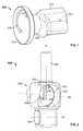
- FIG. 1is an environmental perspective view of a tibial resection guide positioned relative to a knee in extension according to the present teachings
- FIG. 2is an environmental perspective view of the tibial resection guide of FIG. 1 , positioned relative to a knee in flexion;
- FIG. 3is a perspective view of a tibial resection guide according to the present teachings.
- FIG. 3Ais an elevational view of the tibial resection guide of FIG. 3 ;
- FIG. 4is perspective view of a referencing member according to the present teachings.
- FIG. 5is a perspective view of the tibial resection guide of FIG. 3 .
- FIG. 6is a perspective view of a base of the tibial resection guide of FIG. 3 , shown with first and second adjustment members;
- FIG. 7is a perspective view of a first adjustment member of the tibial resection guide of FIG. 3 ;
- FIGS. 8 and 9are perspective views of portions of the tibial resection guide of FIG. 3 ;
- FIG. 10is a perspective view of a portion of an adjustment member of the tibial resection guide of FIG. 3 ;
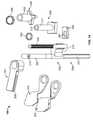
- FIG. 11is perspective view of a tibial resection guide according to the present teachings.
- FIG. 11Ais another perspective view of the tibial resection guide of FIG. 11 ;
- FIG. 12is a perspective view of a macro-adjustment member of the tibial resection guide of FIG. 11 ;
- FIG. 13is a perspective view of the tibial resection guide of FIG. 11 , shown with first and second cutting members in a swung open position;
- FIG. 14is an exploded view of the tibial resection guide of FIG. 11 ;
- FIG. 15is a perspective view of a portion of a tibial resection guide according to the present teachings.
- FIGS. 1 , 2 , 11 and 11 Aan exemplary tibial resection guide 100 according to the present teachings is illustrated.
- Another exemplary tibial resection guide 100 according to the present teachingsis illustrated in FIGS. 3 , 3 A and 5 .
- the tibial resection guide 100is shown positioned relative to a knee joint in extension in FIG. 1 , and in flexion in FIG. 2 .
- the tibial resection guide 100can include a support member 200 , a base member 300 , a cutting guide 203 including a separate first guide portion 202 and a separate second guide portion 204 , and a referencing guide 201 defining a referencing slot 207 .
- the first and second guide portions 202 , 204define a single cutting slot 209 therebetween.
- the first guide portion 202can include one or more fixation holes 213 for securing the first guide portion 202 to the tibia 90 with fixation pins.
- the cutting guide 203can have a curved surface 217 for confirming to and engaging a corresponding tibial surface.
- the referencing member 250can include a holding portion 252 , and an elongated Z-shaped portion that includes a bar or other shaft 254 attached to the handle portion 252 and a stylus arm 256 parallel and connected to the bar 254 at an offset thereof with an intermediate angled portion 255 .
- the intermediate portion 255 and the stylus arm 256are configured to nestingly receive the posterior femoral condyles 82 of a femur 80 in extension and flexion, as shown in FIGS. 1 and 2 .
- a referencing member having a stylus 256 integrally formed as one piece with the referencing guide 201is illustrated in FIG. 15 .
- the first and second guide portions 202 , 204can include corresponding first and second flanges 202 a , 204 a , which, when aligned over one another define the single cutting slot or opening 209 for a saw or other cutting blade or instrument.
- the first and second flanges 202 a , 204 acan be held in the aligned position over one another by a spring biased mechanism, such as a spring-biased ball and recess mechanism, for example.
- the first and second guide portions 202 , 204can be manually rotated relative to one another to overcome the bias, such that the flanges 202 a , 204 a are swung open in a position of misalignment, as shown in FIG.
- the guide portions 202 , 204are not used to define the cutting slot 209 for guiding a cutting blade therethrough.
- the upper flange 202 a of the first guide portion 202can be used as an open cutting guide when the surgeon prefers an open cutting guide rather than a cutting slot for the cutting blade. Further, a sagittal cut can be made in the open cutting guide position.
- the flange 204 a of the second guide portion 204is not configured to and cannot be used by itself as a cutting guide.
- the support member 200can include an extramedullary alignment (EM) guide 206 , an elongated supporting bar or shaft 208 , and a connecting element 210 .
- the EM alignment guide 206 and/or the shaft 208can be removably coupled to the connecting element 210 .
- the EM alignment guide 206 and the shaft 208are held in corresponding channels or slots 205 , 211 defined on an outer surface of the connecting element 210 .
- the shaft 208has a longitudinal axis A.
- the EM alignment guide 206can include a substantially straight first portion 220 having an axis A 1 substantially parallel to the axis A, and a second portion 222 at an angle to the first portion 220 and oriented along an axis A 2 .
- the angle between the axes A and A 1can be made adjustable by allowing angulation of pivoting of the EM alignment guide 206 relative to the shaft 208 , in a range of about 0-15 degrees, for example.
- the second portion 222 of the EM alignment guide 206can include one or more fixation bores or other openings 215 for securing the EM alignment guide 206 to the tibia 90 with fixation screws or pins 219 .
- the base member 300can define a longitudinal bore 302 through which the base member 300 can be slidably mounted on the shaft 208 , as shown in FIGS. 5 and 6 .
- the longitudinal bore 302can include a cutout 330 keyed to the shaft 208 to prevent rotation of the base member 300 about the shaft 208 .
- Gross sliding movement of the base member 300 along the shaft 208 in the direction of axis Acan be controlled with a first gross or macro-adjustment member 304 .
- the first adjustment member 304can be a pin, a set screw, a button, or spring plunger received in a transverse bore of the base member 300 along an axis B 1 and selectively be engaged or disengaged to the shaft 208 .
- the first adjustment member 304can move between a first or engagement position in which the first adjustment member 304 engages the shaft 208 and prevents sliding of the base member 300 along the shaft 208 , and a second or disengagement position in which the first adjustment member 304 does not engage the shaft 208 and allows the base member 300 to slide along the shaft 208 in the direction of a double arrow C.
- the first adjustment member 304can control the gross or macro-adjustment motion of base member 300 .
- the first adjustment member 304can be a push button, which can be spring-biased to a position of engagement with the shaft 208 , preventing sliding motion along the shaft 208 . Depressing the button 304 can disengage the button 304 from the shaft 208 and allow sliding motion along the shaft 208 .
- the base member 300can include a second micro-adjustment mechanism 308 that can control smaller scale or micro-adjustment movement of the base member 300 along the shaft 208 .
- the second adjustment mechanism 308can include a rotatable actuator 310 having a knob 312 with an indicator 314 and a disk 316 .
- the disk 316can be attached to the knob 312 with a neck portion 320 .
- the disk 316can include a curved groove defining a cam 318 .
- the disk 316can be received in a transverse bore 322 defined through the base member 300 along a transverse axis B 2 , which can be substantially orthogonal to the axes A and B 1 , as shown in FIG. 5 .
- micro-adjustment mechanismis discussed below in reference to FIGS. 11-14 . It is also noted that the micro-adjustment mechanism can be used with the stylus arm 256 of the referencing member 250 in position under the posterior femoral condyles 82 , and can provide the surgeon a sense of the tension in the medial collateral ligament.
- the neck portion 320 of the knob 312can pass through an opening 324 of the base member 300 that communicates with the transverse bore 322 .
- the opening 324can define discrete angular positions 326 , such that the knob 312 can be rotated incrementally about the axis B 2 .
- Rotation of the knob 312such that the indicator 314 of the knob moves from a first position 326 to an immediately adjacent position 326 , corresponds to one unit of rotation, which is converted by the second adjustment mechanism 308 to one unit of axial motion along the shaft 208 in the direction of the longitudinal axis A, as discussed below.
- the unit of linear micro-adjustabilitycan be about one millimeter, for example.
- the shaft 208can include a threaded portion 230 with threads 232 and a longitudinal groove or slot or other thread interruption 234 interrupting the circumference of the threads 232 , as shown in FIG. 10 .
- a sleeve 236having a longitudinal bore 239 and first and second ends 242 , 244 , can be placed over a portion of the threaded portion 230 of the shaft 208 .
- An annular flange 243can be formed adjacent the first end 242 of the sleeve 236 and positioned on an upper first surface 306 of the base member 300 .
- the sleeve 236can include a longitudinal extension 238 extending from the first end 242 of the sleeve 236 into the longitudinal bore 302 of the base member 300 .
- a short pin or post 240can be perpendicularly attached to the other end of the extension 238 inside the bore 302 .
- the pin 240can be received in the curved groove 318 of the disk 316 .
- Rotating the knob 312can rotate the curved groove 318 causing the pin 240 to move along the axis A.
- the extension 238moves along the groove 234 and sleeve moves linearly along the axis A.
- each of the first guide portion 202 , the second guide portion 204 , and the referencing guide 201is rotatably mounted on the shaft 208 , such that each of the first guide portion 202 , the second guide portion 204 , and the referencing guide 201 can freely and independently swivel, swing or rotate about the axis A in the directions indicated by the curved arrow D.
- the first guide portion 202 , the second guide portion 204 , and the referencing guide 201can be stacked on one another on the flange 243 of the sleeve 238 over the first surface 306 of the base member 300 .
- the knob 312rotates the knob 312 over one angular increment moves the first guide portion 202 , the second guide portion 204 , and the referencing guide 201 one axial increment along the axis A as one body, without changing their relative positions.
- the distance D between the referencing slot 207 and the cutting slot 209remains constant during motion along the axis A.
- the distance D 1 between the stylus arm 256 and the cutting slot 209remains constant during motion along the axis A.
- the shaft 254 of the referencing member 250is held snugly by the referencing slot 207 , such that the referencing arm 256 is held substantially perpendicularly to the axis A. Keeping the distances D and D 1 fixed can help avoid inadvertent changes of referencing level and free the surgeon from concern over any such inadvertent changes.
- disengaging the gross adjustment member 304 from engagement to the shaft 208allows gross sliding of the base member 300 along the axis A and simultaneous concomitant sliding of the first guide portion 202 , the second guide portion 204 , and the referencing guide 201 without any change in the distances between these guides.
- the distance D between the referencing slot 207 and cutting slot 209remains constant during any adjustment of the tibial resection guide 100 , either by gross adjustment using the first adjustment member 304 or by micro-adjustment using the incremental adjustment knob 312 , as shown in FIG. 5 .
- an alternative micro-adjustment mechanism in the form of a rotatable knob or nut 400 having a sleeve 402 with internal threading and threadably coupled to the threaded portion 230 of the shaft 208can be used instead of the micro-adjustment mechanism 308 illustrated in FIGS. 5-9 .
- Rotating the nut 400moves the nut 400 along the shaft 208 , thereby moving the cutting guide 203 and the referencing guide 201 along the axis A without changing the distance D between the cutting slot 209 and the referencing slot 207 , as discussed above in connection with FIGS. 5-9 .
- Washers 450 , 452can be placed over the shaft 208 above the referencing guide 201 preventing relative movement of the referencing guide 201 and the cutting guide 203 .
- the first adjustment memberis in the form of push button 304 slidably received in a cavity 309 of a base member 300 , which, in this aspect, includes a tubular portion 311 having a longitudinal bore 313 with a D-shaped or other keyed cross-section, through which the shaft 208 can pass and move slidably but not rotatably.
- the button 304defines a corresponding elongated open bore 307 , through which the shaft 208 can pass.
- a spring or other biasing element 305biases the wall of the opening 307 against the shaft 208 preventing sliding along the axis A. Depressing the button 304 , compresses the spring 305 , disengages the shaft 208 from the open bore 307 , and allows sliding along the axis A.
- the tibial resection guide 100can be positioned adjacent to the knee joint in extension and/or flexion, as shown, for determining the tibial resection level.
- the tibial resection guide 100can be attached to the tibia 90 using the EM alignment guide 206 .
- the tibial resection guide of FIG. 11Ais shown in FIGS. 1 and 2 , it will be appreciated that the tibial resection guide 100 of FIG. 3 can be similarly attached to the tibia 90 .
- the referencing member 250can be manually inserted through the referencing slot 207 such that the stylus arm 256 is approximately in position for referencing the posterior condyles of the femur.
- the stylus arm 256can be brought in contact with the posterior condyles first by a gross adjustment using the first adjustment member 304 to slide the base member 300 along the axis A, and then by micro-adjustment using the rotatable knob 312 shown in FIG. 5 or the rotatable nut 400 shown in FIGS. 11 and 11A to incrementally move the first and second guide portions 202 , 204 and the referencing guide 201 along the axis A until the stylus arm 256 of the referencing member 250 can contact the posterior femoral condyles 82 when inserted through the referencing slot 207 . As discussed above, during this movement the distance D between the referencing slot 207 and the cutting slot 209 remains constant and unchanged.
- the first and second guide portions 202 , 204can be rotated away from the tibia 90 during the measurement procedure, and then rotated back toward the tibia 90 for the resection procedures.
- the first guide portion 202can be secured to the tibia 90 with fixation pins or other fasteners passing through the fixation holes 213 .
- the resection levelcan be measured using a length scale associated with angular positions 326 of the rotatable knob 312 of FIG. 5 , as discussed above, or with a scale associated with the rotatable nut 400 of FIG. 11 .
- the referencing guide 201can also be swiveled about the shaft 208 in and out of the referencing position, to facilitate corresponding resection measurement and resection procedures.
- the tibial resection guide 100 of the present teachingsprovides various degrees of gross and micro-adjustability in a linear direction for determining the resection level, as well as independent swiveling motions of the referencing guide 201 and the first and second guide portions 202 , 204 , to enable the surgeon to use the cutting slot in an unobstructed manner and to easily visualize the resection area.
Landscapes
- Health & Medical Sciences (AREA)
- Surgery (AREA)
- Life Sciences & Earth Sciences (AREA)
- Biomedical Technology (AREA)
- Medical Informatics (AREA)
- Oral & Maxillofacial Surgery (AREA)
- Nuclear Medicine, Radiotherapy & Molecular Imaging (AREA)
- Transplantation (AREA)
- Physical Education & Sports Medicine (AREA)
- Engineering & Computer Science (AREA)
- Orthopedic Medicine & Surgery (AREA)
- Heart & Thoracic Surgery (AREA)
- Dentistry (AREA)
- Molecular Biology (AREA)
- Animal Behavior & Ethology (AREA)
- General Health & Medical Sciences (AREA)
- Public Health (AREA)
- Veterinary Medicine (AREA)
- Surgical Instruments (AREA)
- Prostheses (AREA)
Abstract
Description
Claims (20)
Priority Applications (1)
| Application Number | Priority Date | Filing Date | Title |
|---|---|---|---|
| US12/106,773US8162949B2 (en) | 2008-04-21 | 2008-04-21 | Tibial resection guide |
Applications Claiming Priority (1)
| Application Number | Priority Date | Filing Date | Title |
|---|---|---|---|
| US12/106,773US8162949B2 (en) | 2008-04-21 | 2008-04-21 | Tibial resection guide |
Publications (2)
| Publication Number | Publication Date |
|---|---|
| US20090264890A1 US20090264890A1 (en) | 2009-10-22 |
| US8162949B2true US8162949B2 (en) | 2012-04-24 |
Family
ID=41201748
Family Applications (1)
| Application Number | Title | Priority Date | Filing Date |
|---|---|---|---|
| US12/106,773Active2031-02-23US8162949B2 (en) | 2008-04-21 | 2008-04-21 | Tibial resection guide |
Country Status (1)
| Country | Link |
|---|---|
| US (1) | US8162949B2 (en) |
Cited By (10)
| Publication number | Priority date | Publication date | Assignee | Title |
|---|---|---|---|---|
| US20080195110A1 (en)* | 2007-02-13 | 2008-08-14 | Norman Plassy | Device, system and method for positioning or preparing the positioning of a medical operating instrument |
| US20120101505A1 (en)* | 2010-10-26 | 2012-04-26 | Zimmer, Inc. | Patellar resection instrument with variable depth guide |
| US8974459B1 (en) | 2010-05-21 | 2015-03-10 | Howmedica Osteonics Corp. | Natural alignment knee instruments |
| US10456143B2 (en) | 2017-03-02 | 2019-10-29 | Titanium Fusion Technologies, Llc | Composite joint arthroplasty systems and methods |
| US10828046B2 (en) | 2007-09-30 | 2020-11-10 | DePuy Synthes Products, Inc. | Apparatus and method for fabricating a customized patient-specific orthopaedic instrument |
| US11051829B2 (en) | 2018-06-26 | 2021-07-06 | DePuy Synthes Products, Inc. | Customized patient-specific orthopaedic surgical instrument |
| US11406502B2 (en) | 2017-03-02 | 2022-08-09 | Optimotion Implants LLC | Orthopedic implants and methods |
| US11701130B2 (en) | 2021-06-11 | 2023-07-18 | Optimotion Implants LLC | Arthroplasty balance and gap gauge and cutting guidance |
| US11751884B2 (en) | 2021-06-11 | 2023-09-12 | Optimotion Implants LLC | Arthroplasty balance and gap gauge and cutting guidance |
| US12083027B2 (en) | 2017-03-02 | 2024-09-10 | Optimotion Implants LLC | Universal femoral trial system and methods |
Families Citing this family (10)
| Publication number | Priority date | Publication date | Assignee | Title |
|---|---|---|---|---|
| US8702714B2 (en)* | 2006-03-09 | 2014-04-22 | Microsoft Orthopedics Holdings Inc. | Instruments for total knee arthroplasty |
| KR101973101B1 (en) | 2009-05-29 | 2019-04-26 | 스미스 앤드 네퓨, 인크. | Methods and apparatus for performing knee arthroplasty |
| ES2692697T3 (en)* | 2010-02-25 | 2018-12-04 | Depuy Products, Inc. | Custom patient-specific tibial cutting blocks |
| GB201006590D0 (en) | 2010-04-20 | 2010-06-02 | Goodfellow John | Unicondylar knee replacement |
| US8672946B2 (en) | 2011-02-11 | 2014-03-18 | Biomet Manfacturing, LLC | Method and apparatus for performing knee arthroplasty |
| US9386998B2 (en) | 2011-10-27 | 2016-07-12 | Smith & Nephew, Inc. | Devices and methods for performing knee arthroplasty |
| CN104955421A (en) | 2012-10-18 | 2015-09-30 | 史密夫和内修有限公司 | Alignment devices and methods |
| AU2015341696B2 (en)* | 2014-11-07 | 2020-01-30 | Implantcast Gmbh | A method and apparatus for joint reconstruction |
| EP3925547A1 (en)* | 2020-06-19 | 2021-12-22 | Aesculap AG | Intramedullary tibia alignment system |
| US20230372121A1 (en)* | 2022-05-20 | 2023-11-23 | Steensen Orthopedic Systems, LLC | Tibial dual stylus instrument having wide convex stylus tips and components thereof |
Citations (4)
| Publication number | Priority date | Publication date | Assignee | Title |
|---|---|---|---|---|
| WO2006087535A1 (en) | 2005-02-15 | 2006-08-24 | Biomet Uk Limited | Surgical instrument |
| WO2006123120A1 (en) | 2005-05-17 | 2006-11-23 | Biomet Uk Limited | Stylus assembly |
| US7235080B2 (en) | 2003-02-20 | 2007-06-26 | Zimmer Technology, Inc. | Femoral reference tibial cut guide |
| US20080027452A1 (en)* | 2004-12-06 | 2008-01-31 | Garrett Sheffer | Surgical instrument |
- 2008
- 2008-04-21USUS12/106,773patent/US8162949B2/enactiveActive
Patent Citations (4)
| Publication number | Priority date | Publication date | Assignee | Title |
|---|---|---|---|---|
| US7235080B2 (en) | 2003-02-20 | 2007-06-26 | Zimmer Technology, Inc. | Femoral reference tibial cut guide |
| US20080027452A1 (en)* | 2004-12-06 | 2008-01-31 | Garrett Sheffer | Surgical instrument |
| WO2006087535A1 (en) | 2005-02-15 | 2006-08-24 | Biomet Uk Limited | Surgical instrument |
| WO2006123120A1 (en) | 2005-05-17 | 2006-11-23 | Biomet Uk Limited | Stylus assembly |
Cited By (19)
| Publication number | Priority date | Publication date | Assignee | Title |
|---|---|---|---|---|
| US8945132B2 (en)* | 2007-02-13 | 2015-02-03 | Brainlab Ag | Device, system and method for positioning or preparing the positioning of a medical operating instrument |
| US20080195110A1 (en)* | 2007-02-13 | 2008-08-14 | Norman Plassy | Device, system and method for positioning or preparing the positioning of a medical operating instrument |
| US11696768B2 (en) | 2007-09-30 | 2023-07-11 | DePuy Synthes Products, Inc. | Apparatus and method for fabricating a customized patient-specific orthopaedic instrument |
| US11931049B2 (en) | 2007-09-30 | 2024-03-19 | DePuy Synthes Products, Inc. | Apparatus and method for fabricating a customized patient-specific orthopaedic instrument |
| US10828046B2 (en) | 2007-09-30 | 2020-11-10 | DePuy Synthes Products, Inc. | Apparatus and method for fabricating a customized patient-specific orthopaedic instrument |
| US8974459B1 (en) | 2010-05-21 | 2015-03-10 | Howmedica Osteonics Corp. | Natural alignment knee instruments |
| US9113957B2 (en) | 2010-05-21 | 2015-08-25 | Howmedica Osteonics Corp. | Natural alignment knee instruments |
| US9855057B2 (en) | 2010-05-21 | 2018-01-02 | Howmedica Osteonics Corp. | Natural alignment knee instruments |
| US20120101505A1 (en)* | 2010-10-26 | 2012-04-26 | Zimmer, Inc. | Patellar resection instrument with variable depth guide |
| US8747410B2 (en)* | 2010-10-26 | 2014-06-10 | Zimmer, Inc. | Patellar resection instrument with variable depth guide |
| US10512471B2 (en) | 2017-03-02 | 2019-12-24 | Optimotion Implants LLC | Knee arthroplasty systems and methods |
| US11406502B2 (en) | 2017-03-02 | 2022-08-09 | Optimotion Implants LLC | Orthopedic implants and methods |
| US10905436B2 (en) | 2017-03-02 | 2021-02-02 | Optimotion Implants, Llc | Knee arthroplasty systems and methods |
| US10456143B2 (en) | 2017-03-02 | 2019-10-29 | Titanium Fusion Technologies, Llc | Composite joint arthroplasty systems and methods |
| US12083027B2 (en) | 2017-03-02 | 2024-09-10 | Optimotion Implants LLC | Universal femoral trial system and methods |
| US11051829B2 (en) | 2018-06-26 | 2021-07-06 | DePuy Synthes Products, Inc. | Customized patient-specific orthopaedic surgical instrument |
| US11950786B2 (en) | 2018-06-26 | 2024-04-09 | DePuy Synthes Products, Inc. | Customized patient-specific orthopaedic surgical instrument |
| US11701130B2 (en) | 2021-06-11 | 2023-07-18 | Optimotion Implants LLC | Arthroplasty balance and gap gauge and cutting guidance |
| US11751884B2 (en) | 2021-06-11 | 2023-09-12 | Optimotion Implants LLC | Arthroplasty balance and gap gauge and cutting guidance |
Also Published As
| Publication number | Publication date |
|---|---|
| US20090264890A1 (en) | 2009-10-22 |
Similar Documents
| Publication | Publication Date | Title |
|---|---|---|
| US8162949B2 (en) | Tibial resection guide | |
| US11304706B2 (en) | Globalized total knee instrumentation | |
| US7377924B2 (en) | Navigated drill guided resection block | |
| US6979299B2 (en) | Measuring guide for use in orthopedic procedure | |
| EP2496156B1 (en) | Bone positioning device | |
| US7618420B2 (en) | Locking intramedullary jig | |
| US7780672B2 (en) | Femoral adjustment device and associated method | |
| US8317797B2 (en) | Arthroplasty systems and methods for optimally aligning and tensioning a knee prosthesis | |
| US9498199B2 (en) | Distractor instrument | |
| JP5357036B2 (en) | Devices and methods for distal resection of knee prostheses | |
| US7670344B2 (en) | Finely adjustable resection assembly | |
| US11931051B2 (en) | Dual stylus variable angle total knee instruments and methods | |
| EP2822481B1 (en) | Bone positioning device | |
| US8043294B2 (en) | Reference mark adjustment mechanism for a femoral caliper and method of using the same | |
| US12193684B2 (en) | Cutting guide systems and methods | |
| US20230404598A1 (en) | Patella preparation system | |
| US12303142B2 (en) | Intramedullary tibia alignment system | |
| US20060241645A1 (en) | Positioning device for a bone cutting guide | |
| US12303141B2 (en) | Distal femur alignment system | |
| EP1836975A1 (en) | A surgical instrument for locating a cutting plane on a bone |
Legal Events
| Date | Code | Title | Description |
|---|---|---|---|
| AS | Assignment | Owner name:BIOMET MANUFACTURING CORP., INDIANA Free format text:ASSIGNMENT OF ASSIGNORS INTEREST;ASSIGNORS:DUGGINENI, RAJESH V.;MURRAY, DAVID W.;SIGNING DATES FROM 20080312 TO 20080324;REEL/FRAME:020833/0791 Owner name:BIOMET MANUFACTURING CORP., INDIANA Free format text:ASSIGNMENT OF ASSIGNORS INTEREST;ASSIGNORS:DUGGINENI, RAJESH V.;MURRAY, DAVID W.;REEL/FRAME:020833/0791;SIGNING DATES FROM 20080312 TO 20080324 | |
| AS | Assignment | Owner name:BANK OF AMERICA, N.A., AS ADMINISTRATIVE AGENT FOR Free format text:SECURITY AGREEMENT;ASSIGNORS:LVB ACQUISITION, INC.;BIOMET, INC.;BIOMET 3I, LLC;AND OTHERS;REEL/FRAME:023505/0241 Effective date:20091111 | |
| STCF | Information on status: patent grant | Free format text:PATENTED CASE | |
| AS | Assignment | Owner name:BIOMET MANUFACTURING, LLC, INDIANA Free format text:CHANGE OF NAME;ASSIGNOR:BIOMET MANUFACTURING CORPORATION;REEL/FRAME:030656/0702 Effective date:20130603 | |
| FPAY | Fee payment | Year of fee payment:4 | |
| AS | Assignment | Owner name:BIOMET FAIR LAWN LLC, NEW JERSEY Free format text:RELEASE OF SECURITY INTEREST IN PATENTS RECORDED AT REEL 023505/ FRAME 0241;ASSIGNOR:BANK OF AMERICA, N.A., AS ADMINISTRATIVE AGENT;REEL/FRAME:037155/0082 Effective date:20150624 Owner name:BIOMET MICROFIXATION, LLC, FLORIDA Free format text:RELEASE OF SECURITY INTEREST IN PATENTS RECORDED AT REEL 023505/ FRAME 0241;ASSIGNOR:BANK OF AMERICA, N.A., AS ADMINISTRATIVE AGENT;REEL/FRAME:037155/0082 Effective date:20150624 Owner name:EBI HOLDINGS, LLC, INDIANA Free format text:RELEASE OF SECURITY INTEREST IN PATENTS RECORDED AT REEL 023505/ FRAME 0241;ASSIGNOR:BANK OF AMERICA, N.A., AS ADMINISTRATIVE AGENT;REEL/FRAME:037155/0082 Effective date:20150624 Owner name:INTERPORE CROSS INTERNATIONAL, LLC, CALIFORNIA Free format text:RELEASE OF SECURITY INTEREST IN PATENTS RECORDED AT REEL 023505/ FRAME 0241;ASSIGNOR:BANK OF AMERICA, N.A., AS ADMINISTRATIVE AGENT;REEL/FRAME:037155/0082 Effective date:20150624 Owner name:BIOMET LEASING, INC., INDIANA Free format text:RELEASE OF SECURITY INTEREST IN PATENTS RECORDED AT REEL 023505/ FRAME 0241;ASSIGNOR:BANK OF AMERICA, N.A., AS ADMINISTRATIVE AGENT;REEL/FRAME:037155/0082 Effective date:20150624 Owner name:BIOMET 3I, LLC, FLORIDA Free format text:RELEASE OF SECURITY INTEREST IN PATENTS RECORDED AT REEL 023505/ FRAME 0241;ASSIGNOR:BANK OF AMERICA, N.A., AS ADMINISTRATIVE AGENT;REEL/FRAME:037155/0082 Effective date:20150624 Owner name:BIOLECTRON, INC., INDIANA Free format text:RELEASE OF SECURITY INTEREST IN PATENTS RECORDED AT REEL 023505/ FRAME 0241;ASSIGNOR:BANK OF AMERICA, N.A., AS ADMINISTRATIVE AGENT;REEL/FRAME:037155/0082 Effective date:20150624 Owner name:INTERPORE SPINE, LTD., CALIFORNIA Free format text:RELEASE OF SECURITY INTEREST IN PATENTS RECORDED AT REEL 023505/ FRAME 0241;ASSIGNOR:BANK OF AMERICA, N.A., AS ADMINISTRATIVE AGENT;REEL/FRAME:037155/0082 Effective date:20150624 Owner name:BIOMET INTERNATIONAL LTD., INDIANA Free format text:RELEASE OF SECURITY INTEREST IN PATENTS RECORDED AT REEL 023505/ FRAME 0241;ASSIGNOR:BANK OF AMERICA, N.A., AS ADMINISTRATIVE AGENT;REEL/FRAME:037155/0082 Effective date:20150624 Owner name:BIOMET ORTHOPEDICS, LLC, INDIANA Free format text:RELEASE OF SECURITY INTEREST IN PATENTS RECORDED AT REEL 023505/ FRAME 0241;ASSIGNOR:BANK OF AMERICA, N.A., AS ADMINISTRATIVE AGENT;REEL/FRAME:037155/0082 Effective date:20150624 Owner name:BIOMET SPORTS MEDICINE, LLC, INDIANA Free format text:RELEASE OF SECURITY INTEREST IN PATENTS RECORDED AT REEL 023505/ FRAME 0241;ASSIGNOR:BANK OF AMERICA, N.A., AS ADMINISTRATIVE AGENT;REEL/FRAME:037155/0082 Effective date:20150624 Owner name:KIRSCHNER MEDICAL CORPORATION, INDIANA Free format text:RELEASE OF SECURITY INTEREST IN PATENTS RECORDED AT REEL 023505/ FRAME 0241;ASSIGNOR:BANK OF AMERICA, N.A., AS ADMINISTRATIVE AGENT;REEL/FRAME:037155/0082 Effective date:20150624 Owner name:BIOMET EUROPE LTD., INDIANA Free format text:RELEASE OF SECURITY INTEREST IN PATENTS RECORDED AT REEL 023505/ FRAME 0241;ASSIGNOR:BANK OF AMERICA, N.A., AS ADMINISTRATIVE AGENT;REEL/FRAME:037155/0082 Effective date:20150624 Owner name:BIOMET TRAVEL, INC., INDIANA Free format text:RELEASE OF SECURITY INTEREST IN PATENTS RECORDED AT REEL 023505/ FRAME 0241;ASSIGNOR:BANK OF AMERICA, N.A., AS ADMINISTRATIVE AGENT;REEL/FRAME:037155/0082 Effective date:20150624 Owner name:CROSS MEDICAL PRODUCTS, LLC, CALIFORNIA Free format text:RELEASE OF SECURITY INTEREST IN PATENTS RECORDED AT REEL 023505/ FRAME 0241;ASSIGNOR:BANK OF AMERICA, N.A., AS ADMINISTRATIVE AGENT;REEL/FRAME:037155/0082 Effective date:20150624 Owner name:BIOMET HOLDINGS LTD., INDIANA Free format text:RELEASE OF SECURITY INTEREST IN PATENTS RECORDED AT REEL 023505/ FRAME 0241;ASSIGNOR:BANK OF AMERICA, N.A., AS ADMINISTRATIVE AGENT;REEL/FRAME:037155/0082 Effective date:20150624 Owner name:BIOMET BIOLOGICS, LLC., INDIANA Free format text:RELEASE OF SECURITY INTEREST IN PATENTS RECORDED AT REEL 023505/ FRAME 0241;ASSIGNOR:BANK OF AMERICA, N.A., AS ADMINISTRATIVE AGENT;REEL/FRAME:037155/0082 Effective date:20150624 Owner name:BIOMET MANUFACTURING CORPORATION, INDIANA Free format text:RELEASE OF SECURITY INTEREST IN PATENTS RECORDED AT REEL 023505/ FRAME 0241;ASSIGNOR:BANK OF AMERICA, N.A., AS ADMINISTRATIVE AGENT;REEL/FRAME:037155/0082 Effective date:20150624 Owner name:IMPLANT INNOVATIONS HOLDINGS, LLC, INDIANA Free format text:RELEASE OF SECURITY INTEREST IN PATENTS RECORDED AT REEL 023505/ FRAME 0241;ASSIGNOR:BANK OF AMERICA, N.A., AS ADMINISTRATIVE AGENT;REEL/FRAME:037155/0082 Effective date:20150624 Owner name:EBI, LLC, INDIANA Free format text:RELEASE OF SECURITY INTEREST IN PATENTS RECORDED AT REEL 023505/ FRAME 0241;ASSIGNOR:BANK OF AMERICA, N.A., AS ADMINISTRATIVE AGENT;REEL/FRAME:037155/0082 Effective date:20150624 Owner name:ELECTR-OBIOLOGY, LLC, INDIANA Free format text:RELEASE OF SECURITY INTEREST IN PATENTS RECORDED AT REEL 023505/ FRAME 0241;ASSIGNOR:BANK OF AMERICA, N.A., AS ADMINISTRATIVE AGENT;REEL/FRAME:037155/0082 Effective date:20150624 Owner name:EBI MEDICAL SYSTEMS, LLC, INDIANA Free format text:RELEASE OF SECURITY INTEREST IN PATENTS RECORDED AT REEL 023505/ FRAME 0241;ASSIGNOR:BANK OF AMERICA, N.A., AS ADMINISTRATIVE AGENT;REEL/FRAME:037155/0082 Effective date:20150624 Owner name:LVB ACQUISITION, INC., INDIANA Free format text:RELEASE OF SECURITY INTEREST IN PATENTS RECORDED AT REEL 023505/ FRAME 0241;ASSIGNOR:BANK OF AMERICA, N.A., AS ADMINISTRATIVE AGENT;REEL/FRAME:037155/0082 Effective date:20150624 Owner name:BIOMET, INC., INDIANA Free format text:RELEASE OF SECURITY INTEREST IN PATENTS RECORDED AT REEL 023505/ FRAME 0241;ASSIGNOR:BANK OF AMERICA, N.A., AS ADMINISTRATIVE AGENT;REEL/FRAME:037155/0082 Effective date:20150624 Owner name:BIOMET FLORIDA SERVICES, LLC, INDIANA Free format text:RELEASE OF SECURITY INTEREST IN PATENTS RECORDED AT REEL 023505/ FRAME 0241;ASSIGNOR:BANK OF AMERICA, N.A., AS ADMINISTRATIVE AGENT;REEL/FRAME:037155/0082 Effective date:20150624 | |
| MAFP | Maintenance fee payment | Free format text:PAYMENT OF MAINTENANCE FEE, 8TH YEAR, LARGE ENTITY (ORIGINAL EVENT CODE: M1552); ENTITY STATUS OF PATENT OWNER: LARGE ENTITY Year of fee payment:8 | |
| MAFP | Maintenance fee payment | Free format text:PAYMENT OF MAINTENANCE FEE, 12TH YEAR, LARGE ENTITY (ORIGINAL EVENT CODE: M1553); ENTITY STATUS OF PATENT OWNER: LARGE ENTITY Year of fee payment:12 |